


Roadster / Mirage S+ User's Manual
Table of Contents
Section Contents Page
1
Installation &
2
Basic
3
Setup
Operation
Introduction
Maintenance
4
Troubleshooting
5
Specifications
6
1.1 The Projectors...................................................................................................1-1
1.2 List of Components...........................................................................................1-2
1.3 Purchase Record and Warranty Registration....................................................1-3
2.1 Quick Setup ......................................................................................................2-1
2.2 Installation Considerations................................................................................2-3
2.3 Projector Position and Mounting....................................................................2-14
2.4 Source Connections........................................................................................2-17
2.5 Connecting Communications..........................................................................2-20
2.6 Connecting Multiple Projectors......................................................................2-23
2.7 Power Connection...........................................................................................2-26
2.8 Operating Orientation.....................................................................................2-27
2.9 Leveling..........................................................................................................2-27
2.10 Zoom, Focus, and Lens Offset........................................................................2-27
2.11 Keypad Conversion.........................................................................................2-28
3.1 Overview...........................................................................................................3-1
3.2 Projector Basics................................................................................................3-1
3.3 Using the Keypads............................................................................................3-4
3.4 Navigating the Menus.....................................................................................3-11
3.5 Using Inputs and Channels .............................................................................3-14
3.6 Adjusting the Image........................................................................................3-20
3.7 Adjusting System Parameters and Advanced Controls...................................3-35
3.8 Working with PIP or Seamless Switching......................................................3-46
3.9 Working with the Lamp..................................................................................3-49
3.10 Status Menu....................................................................................................3-52
3.11 Using Multiple Projectors ...............................................................................3-53
3.12 Remote Control of the Projector.....................................................................3-64
3.13 Error Conditions .............................................................................................3-64
4.1 Warnings and Guidelines..................................................................................4-1
4.2 Cleaning............................................................................................................4-3
4.3 Replacing Keypad Batteries..............................................................................4-4
4.4 Replacing the Lamp and Filter..........................................................................4-4
4.5 Replacing the Lens............................................................................................4-8
5.1 Displays............................................................................................................5-1
5.2 Lamp.................................................................................................................5-3
5.3 Ethernet.............................................................................................................5-4
6.1 Specifications....................................................................................................6-1
Components/Features..............................................................................3-1
continued…
013-100189 (08/05) Software v1.1 Roadster / Mirage S+ User’s Manual i
REV.1

TABLE OF CONTENTS
Appendices
A Glossary...........................................................................................................A-1
B Remote Keypad................................................................................................B-1
C Serial Communication Cables..........................................................................C-1
D Throw Distance................................................................................................D-1
E System Integration ...........................................................................................E-1
NOTE: Due to continuing research, all information in this manual is subject to change without notice
F Optional Input Modules................................................................................. F-14
ii
Roadster / Mirage S+ User’s Manual
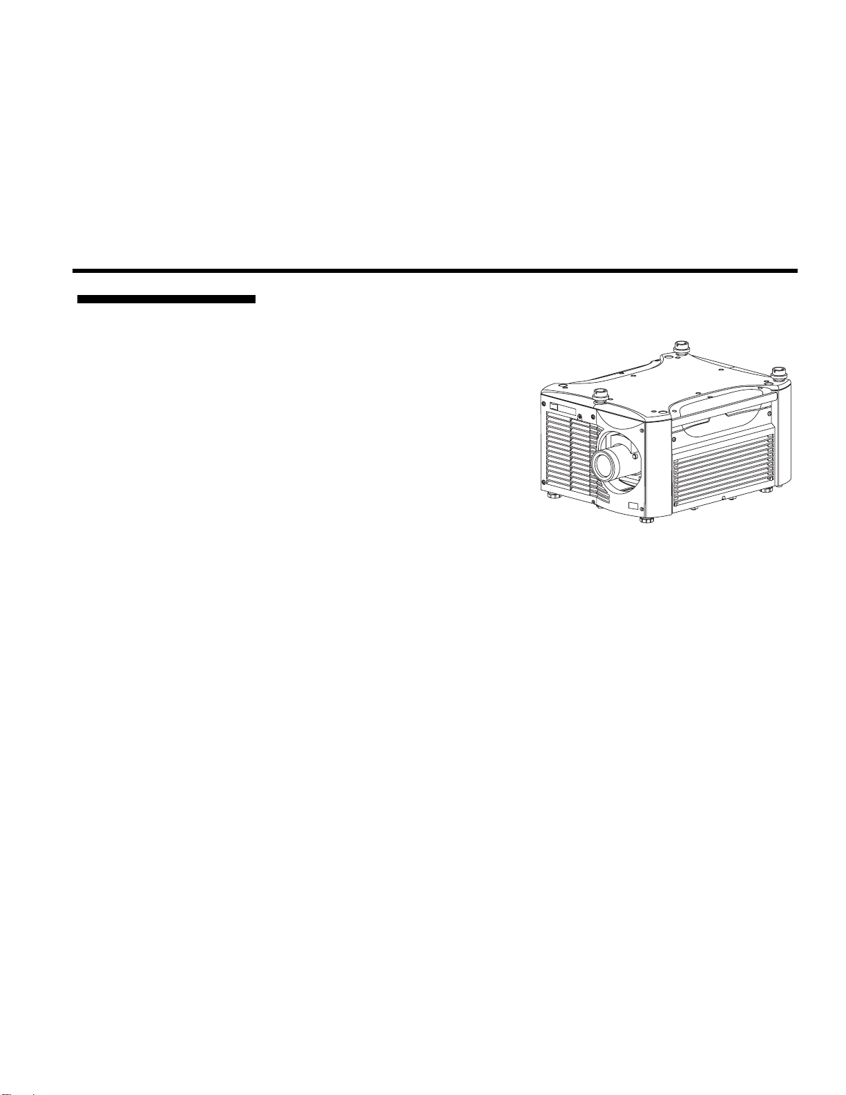
1.1 The Projectors
Section 1
Introduction
The Roadster S+12K/S+16K and Mirage S+14K proje ctors are innov at iv e, high
brightness DMD™ projectors that use next generation Digital Light Processing™
(DLP™) technology from Texas
Instruments. Both projector models
feature compact size, rugged
construction, and integral rigging
hardware, with the Roadster S+ series
ideal for difficult rental/staging
installations of multiple projectors, and
the Mirage S+ series featuring amazing
3D output. A quick-change lamp module,
no-tool lens replacement, and intuitive
user interface means the ultimate in
versatility and ease-of-use. These
projectors provide brilliant images with
Roadster S
1400 x 1050 clarity and perfect color saturation in a wide variety of applications.
+
12K / 16K
Main Features
The Roadster S+ series and Mirage S+ series each have features for your distinct
needs. The stereoscopic Mirage S+ projector provide 3D solutions for power walls,
simulation, and entertainment venues. Both Roadster S+ models include an
additional input module as well as integral hardware required for stacking and flying
up to 3 projectors.
General
DLP™ 3-chip electronics with true 1400 x 1050 (SXGA+) native resolution
10 bit digital video processing
Single-lens design with field-interchangeable, fast-change lens – no tools needed
Modular design for easy serv icing
Built-in handles and multiple rigging points
Lenses
Choice of lenses (from 0.73:1 up to 7.3:1)
Motorized zoom, focus and H/V offsets
Lamps / Light Output
Brightness (ANSI lumens)
Roadster S+12K = 12000 +- 10%
Roadster S+16K = 16000 +- 10%
Mirage S+14K = 16000 +- 10%
Contrast Ratio = 450-600:1 ANSI, 1500 – 1800:1 Full Field (adjustable)
LiteLOC™ for autom atic, consta nt-brightness control
Quick change Bubble lamp module
Roadster / Mirage S+ User’s Manual 1-1

INTRODUCTION
j
Inputs
One analog RGBHV/YPbPr input with 5 BNCs
One DVI-I input for either digital RGB/YCrCb or analog RGB/YPbPr signals
One analog composite-video input
One analog S-video input
Built-in multi-standard video decoder (NTSC, NTSC 4.43, PAL, PAL-M, PAL-
N, PAL-60 AND SECAM)
One Dual SD/HD-SDI input (Roadster S+ series only)
Compatible with all currently used HDTV formats
Special Display Functions
Auto setup with seamless cut-and-fade source switching
Electronic brightness uniformity
Screen-to-screen matching and blending for smooth multiple-projector displays
Communications and Diagnostics
2 standard keypads: built-in and remote (for IR or wired control)
Front and rear IR sensors
Ethernet, RS232, RS422, and GPIO control ports
Easy-view LED for error codes and LCD for status and error messages
Voltmeter for monitoring AC
How The Pro
ectors Work
Roadster S+ series and Mirage S+ series accept data/graphics and video inpu t
signals for projection on to front or rear flat screens. High brightness light is
generated by an internal Bubble lamp, then modulated by three DMD (digital
micromirror device) panels that provide digitized red, green or blue color
information. Light from the “on” pixels of each panel is reflected, converged and
then projected to the screen through the front lens, where all pixels are superimposed
as a sharp full-color image.
Make sure you have received the following standard components:
1.2 Components
Projector
Infrared (IR) remote keypad and conversion cable
Power cord
Using 3D in Mirage Manual
Roadster S+ / Mirage S+ User’s Manual
3D Stereo Sync Cable (Mirage S+ only)
Differences Between Models
Model Name Lamp
Roadster S+12K
Roadster S+16K
Type
2.0 kW
2.4 kW
Dual SD/HD-
SDI Module
Mirage S+14K 2.4 kW Optional
✔
✔
3D Stacking
Not available
Not Available
✔
Mounts
4 Top
Eyebolts
Integral Rigging
✔ ✔ ✔
✔ ✔ ✔
Optional Optional
Hardware
✔
1-2
The 2 Roadster S+ m odels differ in lig ht o utpu t while the Mirage S+ series has 3D
capability but optional stacking hardware. Refer to this manual for all three models.
Roadster / Mirage S+ User’s Manual
1.3 Purchase
Record and
Warranty
Registration
INTRODUCTION
Whether the projector is under warranty or the warranty has expired, Christie’s
highly trained and extensive factory and dealer service network is always available to
quickly diagnose and correct projector malfunctions. Complete service manuals and
updates are available to service technicians for all projectors.
Should you encounter a problem with the projector and require assistance, contact
your dealer or Christie. In many cases, any necessary servicing can be performed on
site. If you have purchased the projector, fill out the Purchase Record below and keep
with your records. In addition, make sure to complete the Product Registration at the
Christie website—this will ensure that you receive all future product communications
promptly.
Purchase Record
Dealer:
Dealer Phone Number:
Projector Serial Number ✽ :
Purchase Date:
Installation Date, if applicable:
✽
NOTE: The projector serial number is located on the projector’s rear identification label
and in the projector’s “Status” menu.
Roadster / Mirage S+ User’s Manual 1-3


Section 2
Installation & Setup
This section explains how to install and set up the projector. If you are familiar with the projector and want to quickly
set it up for temporary use, follow the Quick Setup instructions below. For a more complete setup, follow the
instructions and guides covered in the rem aining subse ctio ns.
NOTE: The lens is not installed for shipping. For instructions on how to install or replace a lens, refer to 4.5,
Replacing the Lens.
Follow these steps for quick setup of the projector in a standard floor mount position.
2.1 Quick Setup
Use either the remote or built-in keypad to work with the projected image.
STEP 1 '
STEP 2 '
STEP 3 '
Position the Projector
Set the projector at the expected throw distance (projector-to-screen distance) and
vertical position. See 2.3, Projector Position and Mounting and Appendix D. Make
sure that the projector is level from side-to-side (see Section 2.9, Leveling).
Connect a Source
Locate the main input panel at the rear of the projector and connector your source to
the appropriate input:
◊ INPUT 1 (upper right area) – RGB input via BNC connectors.
◊ INPUT 2 (left of BNCs) – digital or analog signals (DVI-I) from a computer.
◊ INPUT 3 (upper middle area) – composite video.
◊ INPUT 4 (upper middle area) – S-video.
◊ INPUT 5 (lower area of Roadster S
module which can accept serial digital.
◊ INPUT 6 (lower area ) – for optional input modules (see Appendix F).
Connect to Power
Connect the projector’s line cord to the AC receptacle at the lower rear corner on the
rear the projector, and to proper AC. Use only the line cord provided with the
projector. Power requirements are shown below. Complete information is in Section 6.
+
◊ The Roadster S
◊ The Roadster S
amps @ 200 VAC.
12K requires 200-240 VAC, 50-60 Hz, 13.5 amps @ 200 VAC.
+
16K and the Mirage S+14K require 200-240 VAC, 50-60 Hz, 17.7
+
panel) – a factory-installed Dual SD/HD-SDI
WARNING
Do not attempt operation if the AC supply and cord are not
within the specified voltage and power range. See Section 6.
Roadster / Mirage S+ User’s Manual 2-1
INSTALLATION & SETUP
7
STEP 4 '
STEP 5 '
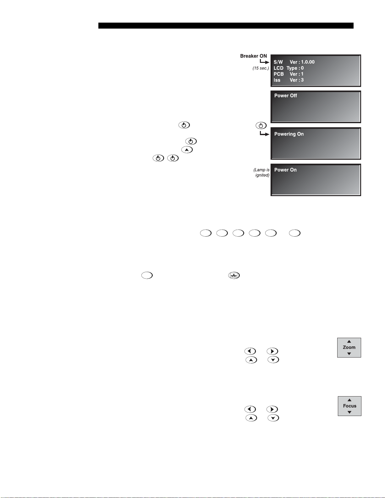
Turn On the Projector and Lamp
1. On the projector, turn the power
breaker/switch on. The LCD Status
Display Window displays the
initializing window for 15 seconds,
then indicates
POWER OFF (see
right).
2. Using the keypad, do one of the
following:
• Press and hold
briefly to
toggle the lamp on.
• Press and release
immediately by
• Press
followed
.
to toggle from the
off state.
The LCD Status Display Window
will display Powering Up and
then, Power On (Figure 2.1) while
the 2 Digit Status/Error Code
Figure 2.1. Turning on the projector
Window will display ON.
Select a Source
Using either keypad, press
,
,
,
Input 5
,
, or
Input 6
to select and display
Input 1
Input 2
Input 3
Input 4
the image for the source you connected in Step 2. The display will resize as needed,
producing an image as large as possible for the type of source present.
STEP 6 '
Optimize the Display
Auto
Setup
Press
on the built-in keypad (or
automated process in which the projector optimizes critical display parameters such as
size, position, pixel tracking, etc., for the current source. Auto Setup can save time in
perfecting a display, and you can modify the adjustments later as desired. See Section 3.
STEP
'
Lens Adjustments
Note: Not applicable to fixed lenses. Focus fixed lens by turning focus ring on lens.
•
ZOOM: With the input image displayed:
o If remote keypad: Press Zoom
o If built-in keypad: Press Zoom
Hold the key down to see the effect –arrows in the display indicate the
direction of the zoom (Figure 2.2).
FOCUS: With the input image displayed:
•
o If remote keypad: Press Focus
o If built-in keypad: Press Focus
Hold the key down to see the effect – arrows in the display indicate
the direction of the focus (Figure 2.3).
on the remote keypad) to initiate an
.
.
.
or
or
or
or .
Figure
2.2
Figure
2.3
2-2
Roadster / Mirage S+ User’s Manual
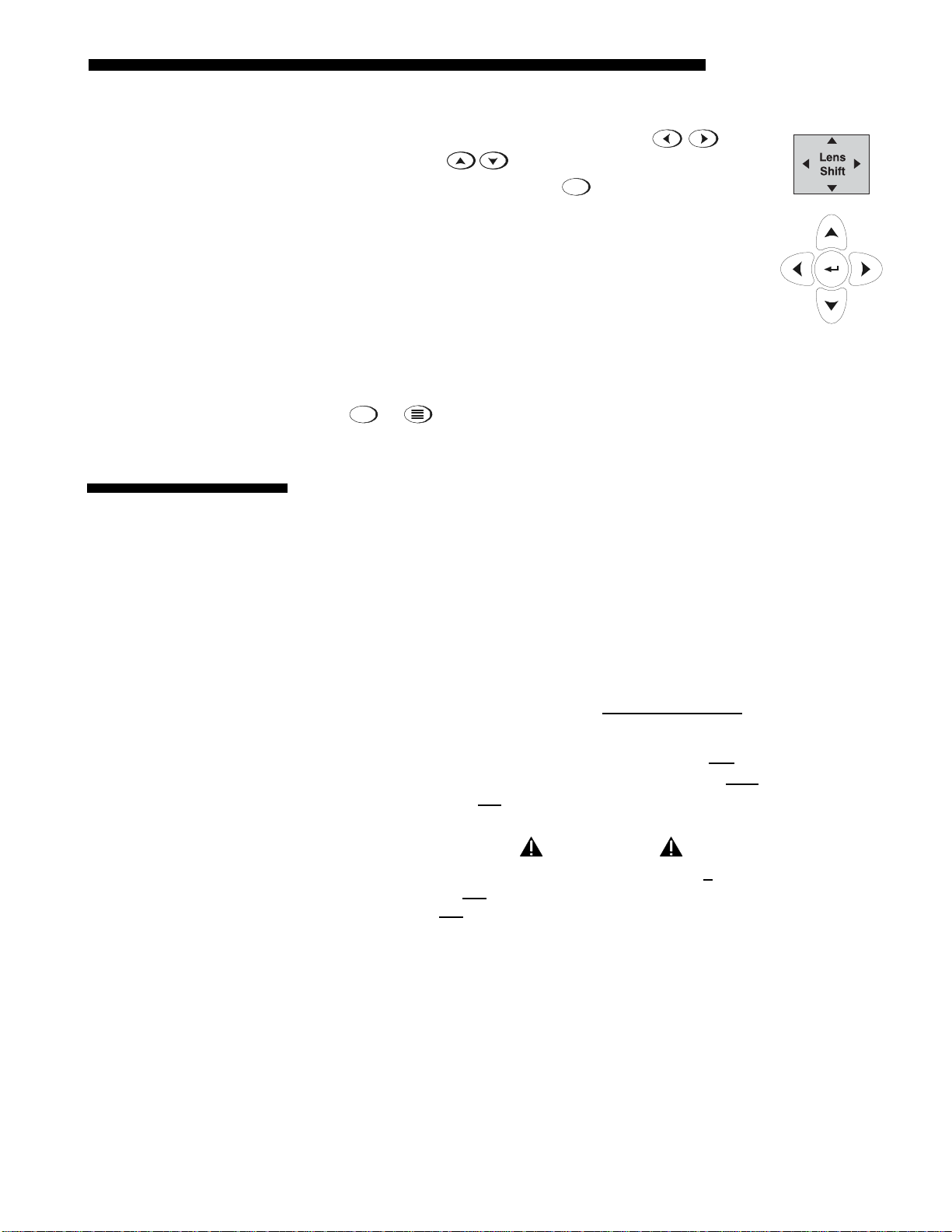
• • LENS OFFSET: To move the image:
INSTALLATION & SETUP
Step 8 '
2.2 Installation
Considerations
o If remote keypad: Press either Lens H
or
Lens V .
Lens
o If built-in keypad: Press
keys.
Shift
and use the arrow
Figure 2.4
Image Adjustments
Menu
Press
or
(remote) to access display parameters described in Section 3
.
Although this projector delivers a high brightness, quality output, final display
quality could be compromised if the projector is not properly installed. This
subsection discusses issues you should consider before proceeding with a final
installation. Even if you do not intend to use the projectors in a fixed and permanent
installation, the following information will help you to better understand what you
can do to enhance display performance
Lifting, Hoisting, '
and Stacking
For any new installation, you will likely have to safely lift or hoist the projector into
place. Keep in mind the following guidelines for safety.
Lifting
All models include handles for convenient hand transport only
, such as when a
projector is lifted from a shipping container to a table. Note the following:
◊ The handles are intended to support the weight of one
◊ The handles are intended to support a projector for a brief
◊ The handles are not
safety points, nor points from which to hoist or suspend
projector only.
time only.
the projector.
WARNINGS
• The handles can’t support more than 1 projector.
• Do not
• Do not
from which to suspend or hoist the projector.
use handles for extended time periods.
use the handles as safety points, or as points
Hoisting
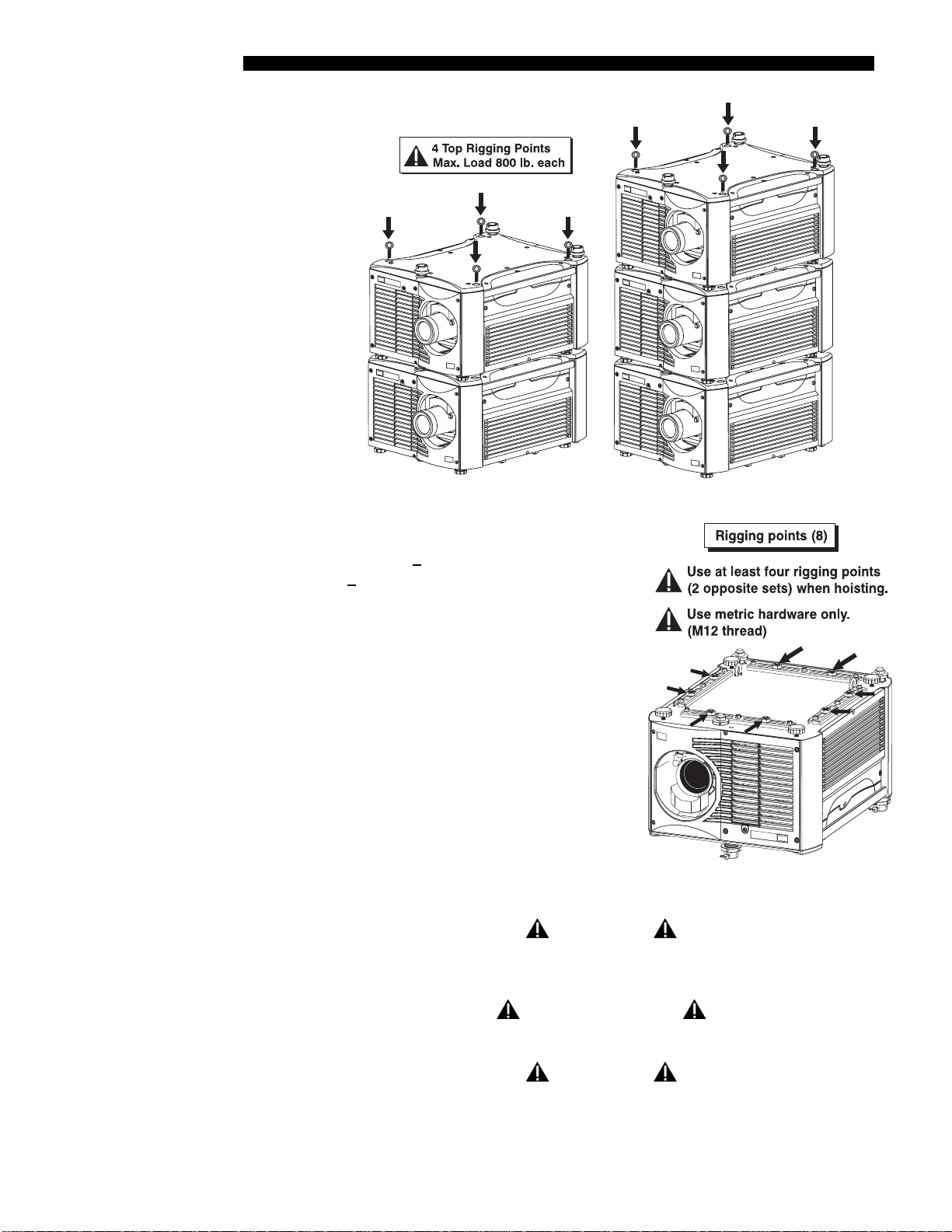
Four integral rigging points on the top of the projector (Figure 2.5) and eight on the
bottom (Figure 2.6) enable either upright or inverted hoisting. For either orientation,
hoist an individual projector, or up to 3 projectors in a stack.
Roadster / Mirage S+ User’s Manual 2-3
INSTALLATION & SETUP
Figure 2.5. Top Rigging Points
RULES FOR ALL HOISTING:
◊ Use at least 4 rigging points for hoisting up
projectors.
to 3
◊ Connect safety cables, and rigging
equipment to the designated locations on
the projector.
◊ Use hoisting and rigging equipment suitable
to your application such as clamps, cables,
eyebolts, or straps, and which accommodate
the load rating. All integral, metric
hardware on the projector accepts an M12
thread only.
◊ Never hoist a projector by its feet, handles,
or any other component (Figure 2.7).
WARNING
Use metric hardware only.
Never force incompatible threads.
Figure 2.6. Bottom Rigging
Points
2-4
RECOMMENDED
Remove the lens before hoisting a projector.
WARNING
Never hoist a projector by its feet,
handles, or any other component.
Roadster / Mirage S+ User’s Manual
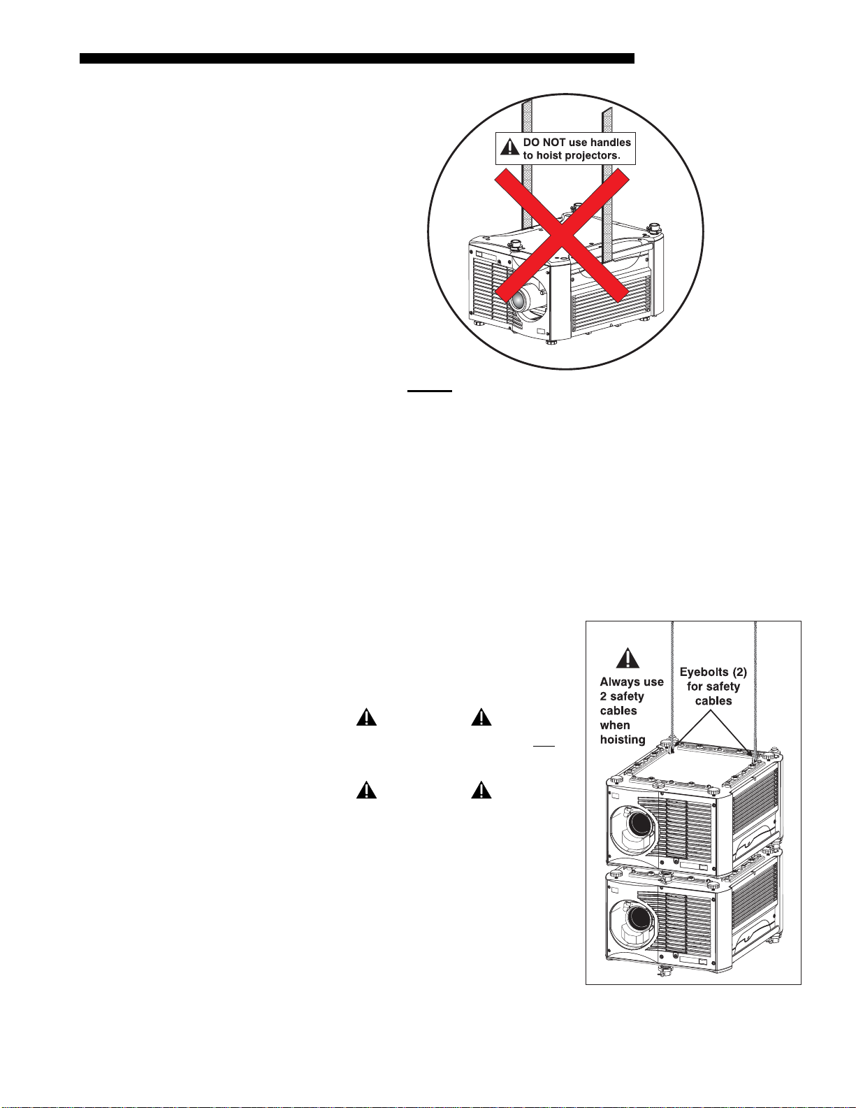
Figure 2.7. NEVER
INSTALLATION & SETUP
Use Handles for Hoisting or as Safety Points
Hoisting Procedure '
STEP 1 '
STEP 2 '
STEP 3 '
This procedure applies to one or more projectors. To hoist a stack, first stack 2 or 3
projectors according to the stacking procedure included in this manual. Never stack
or hoist more than 3 projectors together.
Remove lens (recommended)
To prevent possible lens damage during hoisting, remove the lens. See 4.4, Replacing
the Lamp and Filter.
Retract feet
Retract the adjustable feet if the projector is inverted to prevent the hoisting hardware
from becoming snagged.
Attach safety cables
Attach a safety cable to each of the (2) eyebolts
mounted on the bottom of the projector (Figure
2.8).
WARNING
Always use at least 2 safety cables for any
hoisting.
WARNING
Attach safety cables
to the 2 eyebolts.
NOTE: When hoisting a non-inverted projector
or stack, add 2 safety eyebolts in the front and
rear threaded holes provided on the top of the
projector. Make sure the eyebolts are rated
adequately for the load. Secure safety cabling
to both eyebolts.
Roadster / Mirage S+ User’s Manual 2-5
Figure 2.8. Attach Safety Cables
NOTE: ADD EYEBOLTS (2)
IF NON-INVERTED
INSTALLATION & SETUP
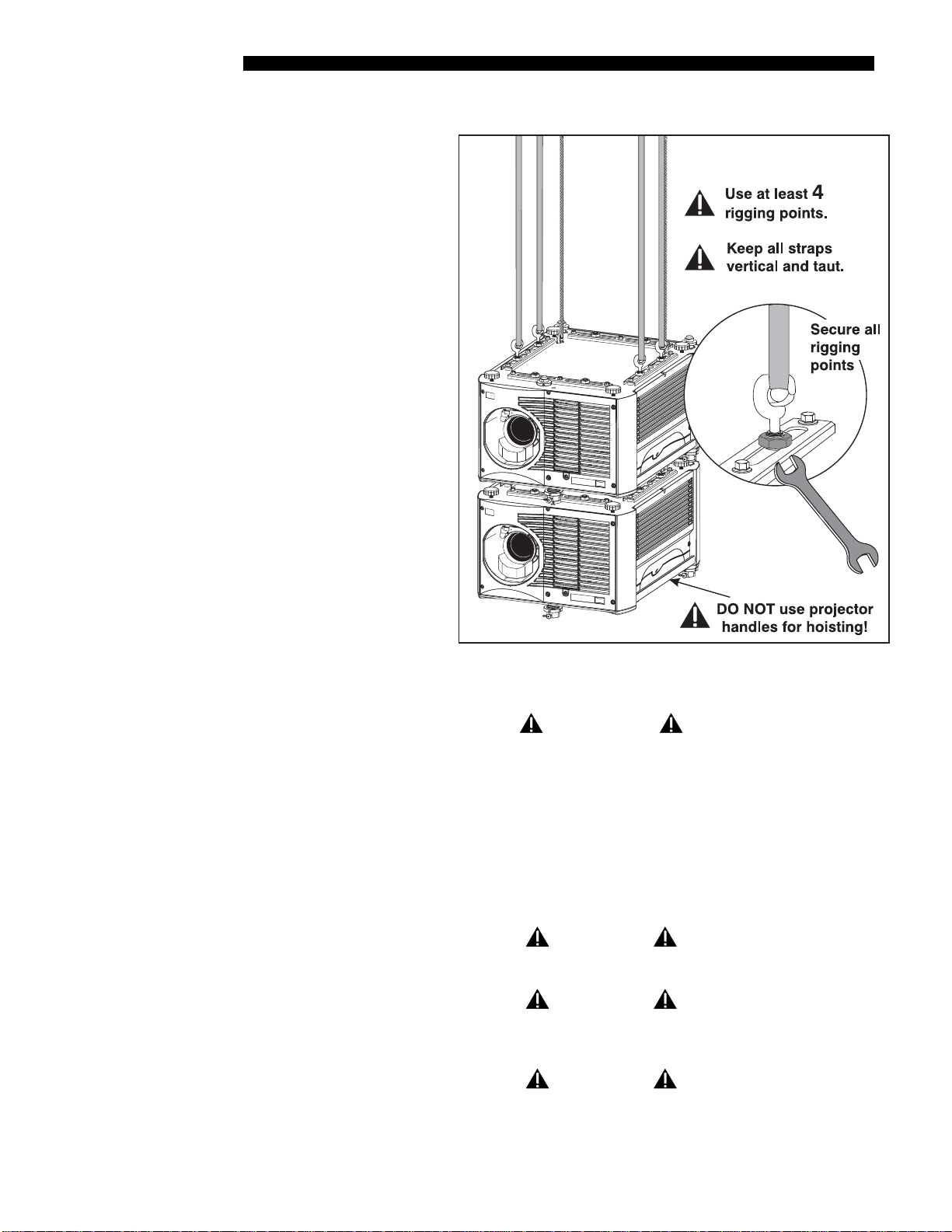
STEP 4 '
Attach rigging hardware
Secure your
rigging
components to the
appropriate rigging
points—8 sliding
points are provided
on the bottom.
Tighten the nut at
each required
location (Figure
2.9) to prevent
sliding.
NOTE: 1) Use at
least 4 rigging
points for all
hoisting. 2) Use
straps, clamps or
cabling with load
capacity adequate
for the total
projector weight.
See Section 6. 3)
Do not join the
rigging straps or
cables to a
common point—
keep separated as
shown.
Figure 2.9. Using the Rigging Hardware
Stacking Procedure '
2-6
Roadster / Mirage S+ User’s Manual
WARNINGS
• Maximum stack = 3 projectors.
• Stack first, then hoist.
NOTES: 1) Requires stacking hardware provided standard with Roadster S+ only.
Available separately for M irage S
+
Roadster S
and Mirage S+ projectors can be stacked in either the upright or inverted
+
. 2) Requires at least 2 people.
position. Do not mix orientations—i.e., inverted with upright—in a stack. Secure a
maximum of 3 projectors with the stacking mounts as described below.
WARNING
Do not stack more than 3 projectors.
WARNING
Christie stacking hardware required. The top
projector could slide off and cause injury or death.
WARNING
Never carry a stack.
INSTALLATION & SETUP
STEP 1 '
STEP 2 '
Position the projectors
Place the projectors to be
stacked on a secure table or
cart.
• Place one projector on its
side to access its
adjustable feet and
stacking legs (Figure
2.10).
• Orient the other projector
in either upright or
inverted position as
required (remember,
each projector in a stack
must be in the same
orientation).
Figure 2.10.
Fully retract the (4) adjustable feet
Retract each foot as far as possible by turning it clockwise.
• If upright – retract the feet on top projector.
• If inverted – retract the feet on bottom projector.
STEP 3 '
STEP 4 '
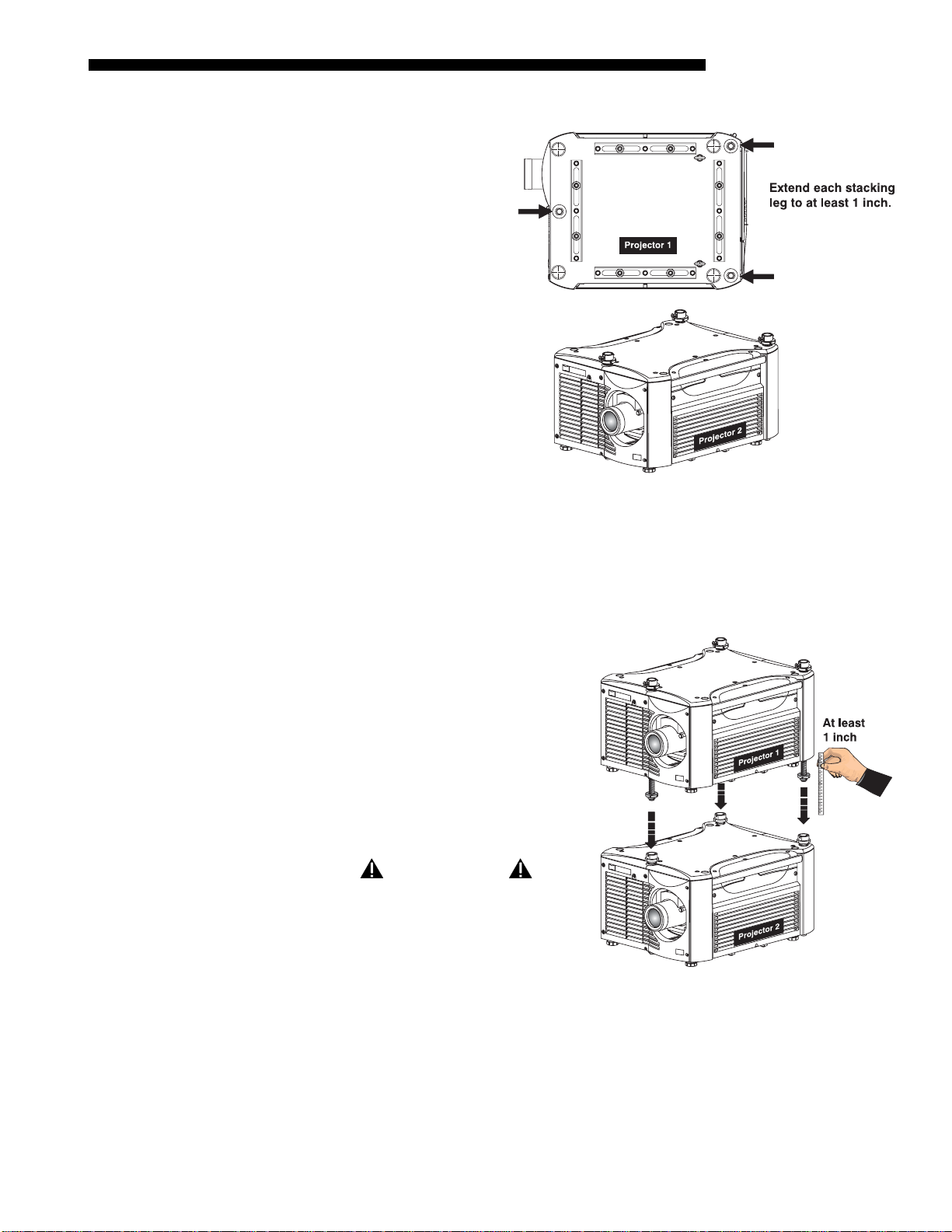
Extend the (3) stacking legs
Extend the stacking legs by turning
them so that at least 1 inch of thread is
visible on each. This clearance
accommodates the up-or-dow n
movement for aligning the images from
stacked projectors. Extend all 3 legs
equally (Figure 2.11).
• If upright – extend legs on top
projector (shown).
• If inverted – extend legs on bottom
projector.
IMPORTANT
Extend the stacking legs
equally by at least 1 inch.
Figure 2.11. Extend 3 Stacking Legs
(UPRIGHT STACK SHOWN)
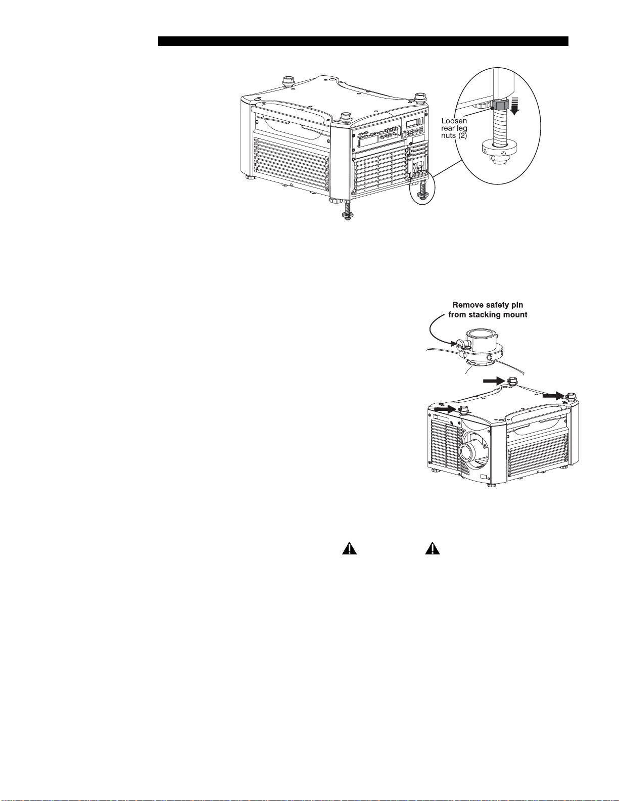
Loosen the rear stacking leg nuts
On the rear stacking legs, loosen the nuts so the legs have some lateral movement for
easier alignment with the stacking mounts on the other projector.
Roadster / Mirage S+ User’s Manual 2-7
INSTALLATION & SETUP
7
Figure 2.12. Loosen 2 Nuts
• If upright – release on top projector.
• If inverted – release on bottom projector.
STEP 5 '
STEP 6 '
Release and remove (3) safety pins
The safety pins must be removed from the
stacking mounts so that the stacking legs can fit
into the mounts (Figure 2.13).
• If upright – remove the pins from the mounts
on the bottom projector.
• If inverted – remove the pins from the
mounts on the top projector.
Place top projector on bottom projector
WARNING
Minimum of 2 people required.
Figure 2.13. Remove Safety Pins
With one person on each side, lift the top projector on to bottom projector, aligning
all three stacking points between projectors. Legs should fit inside stacking mounts.
STEP
'
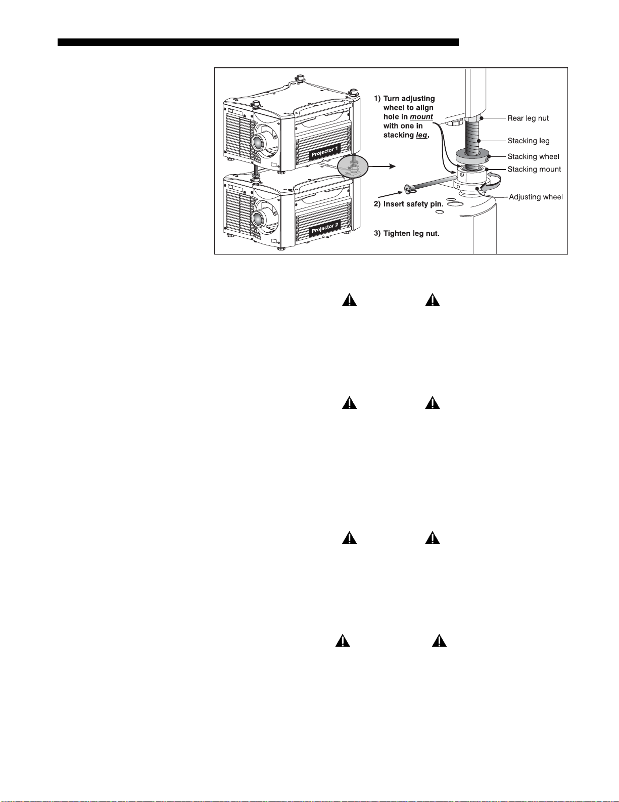
Align holes in (3) stacking mounts and (3) stacking legs.
On each stacking mount, turn the adjusting wheel slightly until the hole in the top
portion of the mount lines up with the hole in the stacking leg (Figure 2.14).
NOTE: You can increase leverage by using a screwdriver in the holes.
2-8
Roadster / Mirage S+ User’s Manual
INSTALLATION & SETUP
Alig
Figure 2.14. Align Holes in Mounts and Legs, and LOCK with Pin
STEP 8 '
STEP 9 '
STEP 10 '
Insert (3) safety pins and LOCK all
WARNING
Critical Safety Procedure.
At each of the (3) stacking points, insert the safety pin fully through the holes in the
stacking mounts and stacking legs (Figure 2.14). Ensure that each pin is fully inserted to
engage the safety lock and secure the projectors together. Failure to engage the safety
lock could cause the projectors to separate and result in injury or death.
WARNING
Failure to engage the safety lock could cause the
projectors to separate and result in injury or death.
Leg Nuts
Before hoisting, firmly tighten the nuts on the (2) rear stacking legs (Figure 2.14). Or,
if you are ready to align the projectors to one another, leave these nuts slightly loose
until after the alignment.
Repeat STEPS 1–9 for a third projector.
WARNING
Never stack more than 3 projectors.
nment Procedure '
Stacked projectors must be correctly aligned to one another so that the resulting
display is optimized and as sharp as possible. If you are also hoisting the stack, hoist
the stack into place first, then align. Lock all stacking hardware into place to m ain tain
your alignment.
IMPORTANT
Make sure the stacking legs have been extended
by at least 1 inch, and are slightly loosened.
Refer back to
Roadster / Mirage S+ User’s Manual 2-9
Figure 2.11.
INSTALLATION & SETUP
Before You Begin
Always align to the fixed projector. In floor-mount or table-mount (i.e., non-
hoisted) stacks, you will align to the bottom projector as shown in drawings
below. In hoisted stacks, align to the top projector.
Leg nuts must be loosened before alignment, otherwise the stacking mounts will
not turn and allow movement of the projector.
STEP 1 '
STEP 2 '
STEP 3 '
STEP 4 '
STEP 5 '
Position the first image (fixed projector)
Position the fixed projector’s image as desired and align the other image(s) to it as
described below.
Display the grid test pattern
To distinguish each image, enable “Red” for one display and “Green” for the other.
See 3.3, Using the Keypads if you need help enabling colors.
Adjust zoom and focus
Minimize each projector’s zoom and images are in focus.
Try aligning the two grid patterns
Adjust zoom and offset on the top projector to precisely move its test pattern display
on to the bottom test pattern. When properly aligned, all red/green grid lines in the
combined image will turn yellow.
• If all lines are well-aligned, skip to STEP 7 to lock all stacking mounts.
• If alignment needs improvement, proceed with the next step.
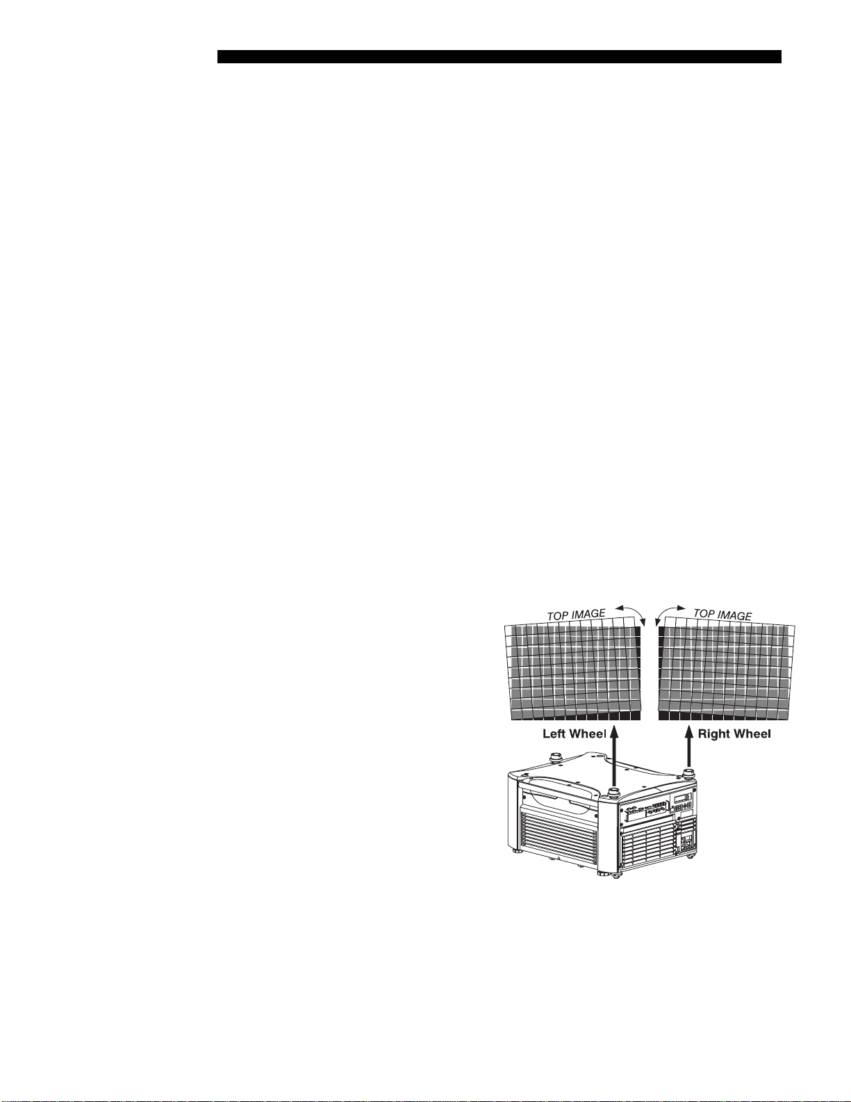
Align the center lines of the grid
Turn the (2) rear stacking mount
wheels to move the top projector
as necessary for well-aligned
center lines. Use a screwdriver in
the holes around the rim of each
adjusting wheel for better leverage
and control.
2-10
HOW TO MOVE THE IMAGE:
Turned independently, each
stacking mount acts as a pivot
point for the opposite edge of the
display (see right). For example,
turn the right mount to tilt the left
portion of the image up or down,
and turn the left mount to tilt the
right portion of the image up or
down. Turn together to raise or
lower the top image like an offset adjustment, or turn the front stacker.
IF THE CENTER LINES FORM AN “X”: This indicates that the projectors (and images)
are slightly tilted in relation to one another. Turn one mount to raise one side, and/or
turn the other mount to lower other side. See Figure 2.15.
Roadster / Mirage S+ User’s Manual
Figure 2.15. Adjustment Directions (Tilt)
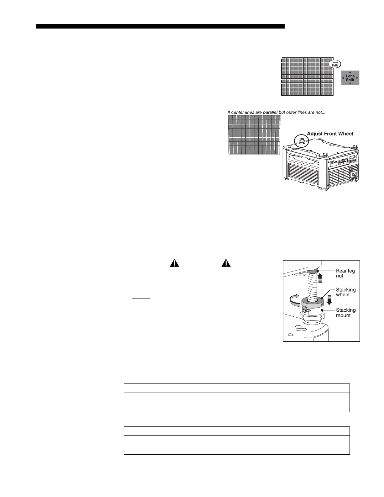
IF THE CENTER LINES ARE PARALLEL BUT MISALIGNED:
7
yp
• If centerlines are out by the same amount from top
and bottom – use offsets (on top projector) to bring
the centerlines into alignment.
INSTALLATION & SETUP
• If centerlines are parallel but
others are not, turn the front
stacking mount wheel to bring
the centerlines into alignment.
STEP 6 '
Align the edges of the grid
With center lines aligned, adjust zoom (top projector) to align the edges of its image
with the other image. Then adjust focus. When aligned, all lines from the combined
red/green grids will be yellow.
STEP
'
Secure all stacking wheels and leg nuts
WARNING
Critical Safety Procedure.
STEP 8 '
Installation T
e '
Turn all (3) stacking wheels until they are firmly
secure against the rest of the stacking mount.
Secure both (2) rear leg nuts against the bottom of
the projector.
Repeat steps 1 to 7 for a third projector
Choose the installation type which suits your needs:
front or rear screen, floor mount or inverted mount.
Front Screen, Floor Mount Installation
ADVANTAGES CONSIDERATIONS
• Easy to set up
• Can be moved or changed quickly
• Easy to access
Front Screen, Inverted Mount (ceiling) Installation
ADVANTAGES CONSIDERATIONS
• Does not take up audience space
• Projector is unobtrusive
• Projector cannot be accidentally moved
• Shares floor space with audience
• Installation is more permanent
• It is more difficult to access the projector
Figure 2.16. Secure All
Hardware
Roadster / Mirage S+ User’s Manual 2-11
INSTALLATION & SETUP
yp
Rear Screen, Floor Mount Installation
ADVANTAGES CONSIDERATIONS
• Projector is completely hidden
• Projector is easily accessed
• Usually good ambient light rejection
Rear Screen, Inverted Mount (ceiling) Installation
ADVANTAGES CONSIDERATIONS
• Projector is completely hidden
• Usually good ambient light rejection
Rear Screen, Floor Mount with Mirror
ADVANTAGES CONSIDERATIONS
• Projector is completely hidden
• Usually good ambient light rejection
• Requires less space behind screen than
other rear screen installations
• Requires separate room
• Requires rear projection screen
• Requires separate room
• Installation cost is usually higher
• Requires separate room
• Installation cost is usually higher
Screen T
e '
Front Screen Installations
While there are two basic screen types, flat and curved, generally flat screens are
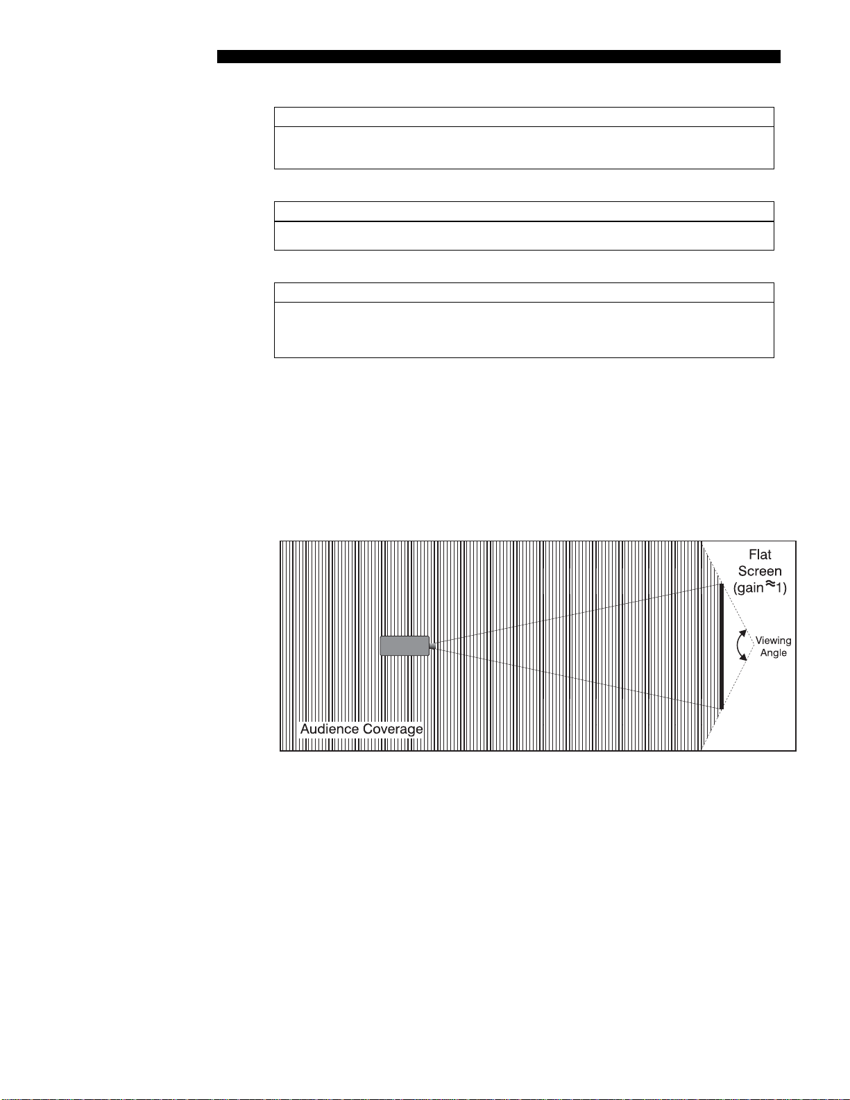
recommended for this projector (Figure 2.17)X. Flat screens offer a gain of about 1
with a viewing angle just less than 180°. Incident light reflects equally in all
directions so the audience can see the display from various angles. Because of the
low gain, flat screens are most effective when ambient lighting is reduced, although
this difference may be negligible given the high brightness output from this projector.
Figure 2.17. Audience Coverage with Flat Screen Figure 2.17
NOTE: Lenses for this projector are designed primaril y for use with flat scr eens, but
the projector depth-of-field range allows the lens to be focused on curved screens as
well. While focus remains sharp in the corners, there may be significant pincushion
distortion, primarily at the top of the screen.
2-12
Rear Screen Installations
There are two basic types of rear screens: diffused and optical . A diffused screen has
a surface which spreads the light striking it. Purely diffused screens have a gain of
less than 1. The main advantage of the diffused screen is its wide viewing angle,
similar to that of a flat screen for front screen projection. Optical screens take light
from the projector and redirect it to increase the light intensity at the front of the
screen. This increase at the front reduces the intensity in other areas. A viewing cone,
similar to that of a curved front screen install ation, is crea ted.
Roadster / Mirage S+ User’s Manual
INSTALLATION & SETUP
p
Ambi
To summarize, optical screens are better suited for brightly lit rooms where the
audience is situated within the viewing cone. Diffused screens may be better suited
when a wide viewing angle is required but there is low ambient room lighting.
Screen Size '
Screen As
ect Ratio '
Screen size may vary from 4 feet (122 cm) to 45 feet (1372cm) diagonal, depending
on the lens you are using. For instance, a 0.73:1 lens can produce a 5 foot (150 cm) to
a 14 foot (548 cm) image size depending on the location of the projector, whereas a
4.5-7.3:1 zoom lens produces an 8 foot(160 cm) to 40 foot (438 cm) image size.
Choose a screen size appropriate for your lens and application. Keep in mind that if
the projector will be used to display text information, the image size must allow the
audience to recognize all text clearly. The eye usually sees a letter clearly if eye-totext distance is less than 150 times the height of the letter. Small text located too far
from the eye may be illegible at a distance no matter how sharply and clearly it is
displayed.
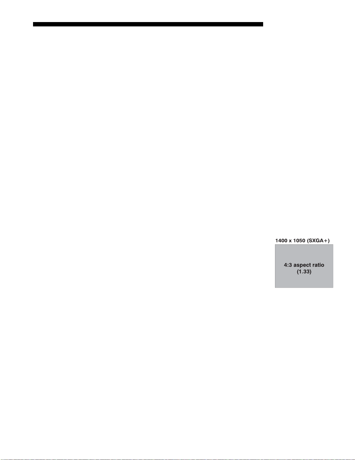
Ideally, to fill a screen with an image, the aspect ratio of the screen should be equal to
the aspect ratio of the image. The aspect ratio of an image is expressed as the ratio of
its width to its height such as a 4:3 aspect. Standard video from a VCR has a 4:3
aspect ratio. For example, to display a VCR output with a 4:3 aspect ratio onto a 10
foot (3m) high screen, the width of the screen must be at least 13.3 feet (4m).
Aspect ratio (Figure 2.18) describes the proportion of the screen and is expressed as
the ratio of width to height, such as “4:3” or “5:4”. Although image size and image
aspect ratio can both be adjusted quickly through projector software, it is still a good
idea to choose a screen aspect ratio which is most appropriate for your intended
applications.
Ideally, to exactly fill a screen with an image, the aspect
ratio of the screen should correspond to the aspect ra ti o of
the image, which depends on the source in use. For
example, standard video from a VCR has a 4:3 ratio
(approximately), whereas a high resolution graphics signal
typically has a 5:4 aspect ratio. By default, images from
your projector will be as large as possible and will maintain
their aspect ratio.
Figure 2.18. Aspect
The SXGA+ (1400 x 1050) aspect ratio for the Roadster
Ratio
and Mirage models is 4:3.
ent Lighting '
Other Considerations '
The high brightness of this projector is well suited for locations where ambient
lighting might be considered less than ideal for projection. Even a typical room or
large auditorium fully lit with ceiling lights and windows rarely requires special
attention. Contrast ratio in your images will be noticeably reduced only if light
directly strikes the screen, such as when a shaft of light from a window or floodlight
falls on the image. Images may then appear washed out and less vibrant.
In general, avoid or eliminate light sources directed at the screen.
Other considerations and tips which can help improve your installation:
• Keep the ambient temperature constant and below 35°C (95°F). Keep the
projector away from heating and/or air conditioning vents. Changes in
temperature may cause drifts in the projector circuitry which may affect
performance.
Roadster / Mirage S+ User’s Manual 2-13
INSTALLATION & SETUP
2.3 Projector
Position and
Mounting
Throw Distance '
• Keep the projector away from devices which radiate electromagnetic energy such
as motors and transformers. Common sources of these include slide projectors,
speakers, power amplifiers, elevators, etc.
• Choose the best screen size for the application. Since m ore mag n ifica tion reduce s
brightness, use a screen size appropriate for the venue but not larger than
required. Installing a large screen in a small room is similar to watching
television at a close range; too large a screen can overpower a room and interfere
with the overall effect. A good rule of thumb is to be no closer than 1.5 times the
width of the screen.
Installation type, screen type, and lighting all affect where the projector is positioned.
In addition, both throw distance (the distance between the pro jector and scre en) an d
vertical position (the height of the projector in relation to the screen) must be
determined for every new installation. Both depend on the screen size and lens type
you are using. Make sure that the room can accommodate the required position of the
projector for the chosen screen size.
2-14
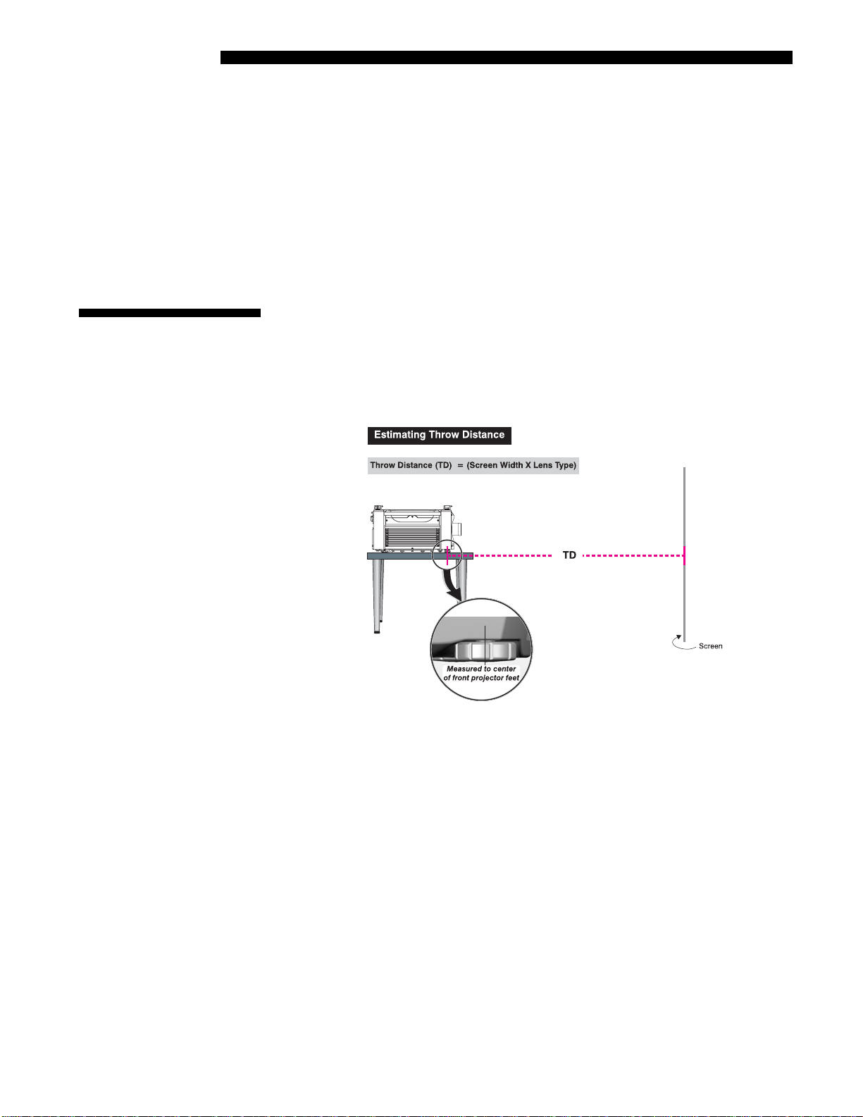
Figure 2.19. Estimating Throw Distance
(SEE APPENDIX D)
For any installation, an accurate throw distance (TD) must be determined in order for
the image to be of the right size for your screen–the farther the projector is from the
screen, the larger the image. Throw distance is the distance between the projector’s
front feet axes and the screen (Figure 2.19), and is roughly equal to the horizontal
width of the screen multiplied by the throw ratio of the installed lens. Once you know
your screen size and lens, you can estimate throw distance needed. For example:
• Screen Width = 10 feet
• Lens Type is 0.7:1
• Throw Distance (TD) = 10 feet x 0.7 = 7 feet
NOTES: 1) If your projector is slightly tilted in relation to the screen, typical for
large venues or flown installations, throw distance still represents the smallest
measurement between the screen and front feet. 2) For proper placement in an
installation, always refer to the throw distance formula and/or chart for your lens as
listed in Appendix D. Keep in mind that due to lens manufacturing tolerances for
Roadster / Mirage S+ User’s Manual
INSTALLATION & SETUP
lens focal length, actual throw distance can vary ±5% between lenses described as
having the same throw ratio
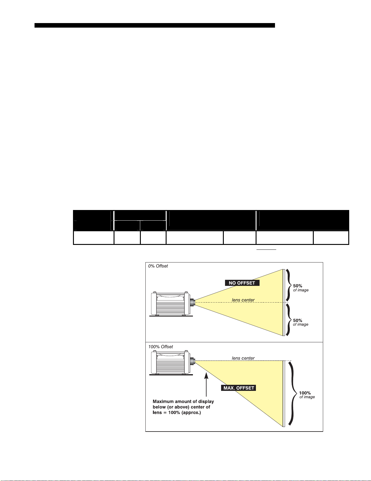
Vertical & Horizontal '
Position
Lens Type Offset Movement
or or
All motorized
lenses
THE VERTICAL POSITION of the projector in relation to the scre en also depen ds on the
size of the screen and the lens type. Correct vertical position helps ensure that the
image will be rectangular in shape rather than keystoned (having non-parallel sides)
and that image focus and brightness both remain optimized.
If necessary, vertical position of the image can be offset—that is, moved up or down
in relation to lens center—by using the motorized offset function. Starting with no
offset, the 1400 x 1050 image from this projector can be moved up or down by a
maximum distance of 525 pixels, resulting in all of the image displayed above or
below lens center. See Table 2.1 and Figure 2.20. NOTE: Not applicable to the fixed
0.73:1 lens.
THE HORIZONTAL POSITION of the image can be offset—that is, shift ed lef t or right
of lens center—by using the motorized offset function. Starting with no offset, the
1400 x 1050 image from this projector can be moved left or right by a maximum
distance of 350 pixels, resulting in 75% of the image displayed to one side of lens
center. See Table 2.1 and Figure 2.21.
Table 2.1. Maximum Amount of Image Offset from Lens Center
Max. Amount of Display
Above or Below Lens Center
100%
(525 pix)
NOTES: 1) Offsets are not available with 0.73:1 fixed lens. 2) When offset movement is stated as a percentage (see left
columns), this represents the percentage of ½ image height or½ image width 3) All offset values are ±7%.
50%
(350 pix)
1050 pixels or 100% 1050 pixels or 75%
Max. Amount of Display
Right or Left of Lens Center
Figure 2.20. Maximum Vertical Offset
Roadster / Mirage S+ User’s Manual 2-15
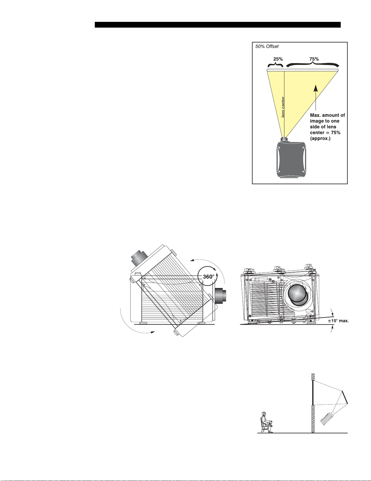
INSTALLATION & SETUP
NOTES: 1) If the image becomes keystoned or
exhibits uneven brightness, the projector may
simply be too high or low in relation to the
screen. 2) Recommended offset ranges can be
exceeded, however this may affect image
quality. 3) Simultaneous horizontal and
vertical offset limits the adjustment range of
each. 4) Offset can vary by ±7% and may be
affected by the degree of zoom currently in
use.
Tilting the Projector '
Figure 2.21. Maximum Horizontal
Offsets
The projector can be rotated and mounted at any vertical angle—i.e., you can tilt the
face of the projector up or down as much as desired for your installation. Side-to-side
tilt, however, must not exceed 15°. This limit ensures that the lamp in the projector
operates properly and safely. Always vent exhaust air away from the lens.
Figure 2. 22. Vertical and Horizontal Tilt Ranges
For permanent ceiling mount installations, use the Christie ceiling mount fixture
designed for your projector. For more information, contact your dealer.
Folded Optics '
2-16
Roadster / Mirage S+ User’s Manual
In rear screen applications (Figure 2.23)where
space behind the projector is limited, a mirror
may be used to fold the optical path. The
position of the projector and mirror must be
accurately set. Consult your dealer or Christie
for details.
Figure 2.23. Rear Screen
2.4 Source
Connections
INSTALLATION & SETUP
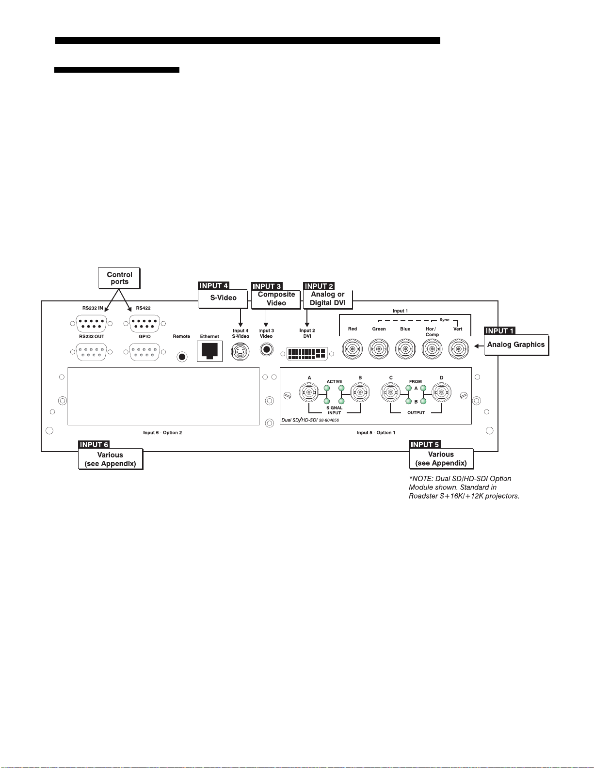
Sources connect to the Input Panel located on the rear of the projector. As shown in
Figure 2.24, the upper right corner (
INPUT 1) typically accepts an RGB signal from
an external analog RGB source, or it can also be used for YPbPr signals or additional
video sources. Just to the left of the BNCs, the DVI-I connector (
INPUT 2) accepts
digital or analog display signals from a computer. Connect analog composite video at
INPUT 3, or S-video at INPUT 4 from devices such as VCRs, laser disk players, or
DVD players. At
compatible SMPTE signals (note this module can be moved to
INPUT 5 (below INPUT 1), connect serial digital YCbCr (4:2:2) or
INPUT 6 if desired)..
There are also several optional interfaces available for connecting other sources—
these interfaces slide into the remaining unused option slot, and can be done while
the projector is running.
NOTES: 1) See Section 6, Specifications for details regarding compatible inputs. 2)
Use high quality shielded cables only for all connections. 3) The Dual SD/HD-SDI
module shown is standard on the Roadster S+, optional for the Mirage S+ series.
RGB Signals '
Figure 2.24. Input Panel
INPUT 1consists of 5 BNCs (connectors) for linking to a variety of RGB sources such
as a PC, Mac, DEC, Sun, SGI, and others. This projector supports multiple sync
types with RGB signals: sync-on-green, composite sync, and separate H & V syncs.
NOTE: Depending on your source, you may need a custom adapter cable with BNC
connectors at the projector end and a different type of connector at the other (such as
a 15-pin “D” connector for some computer sources). Contact your dealer for details.
Connect the
outputs to the
SYNC BNC input(s) first. Then connect the red, green, and blue source
RED, GREEN, and BLUE BNCs on the INPUT 1 panel. If the source uses
sync-on-green, only the red, green, and blue connections are required. If the source
provides a composite sync output, connect it to the
SYNC input labeled HOR/COMP. If
the source provides separate horizontal and vertical sync outputs, connect horizontal
sync to the
labeled
Roadster / Mirage S+ User’s Manual 2-17
SYNC input labeled HOR/COMP, and connect vertical sync to SYNC input
VERT. See Figure 2.25, below.
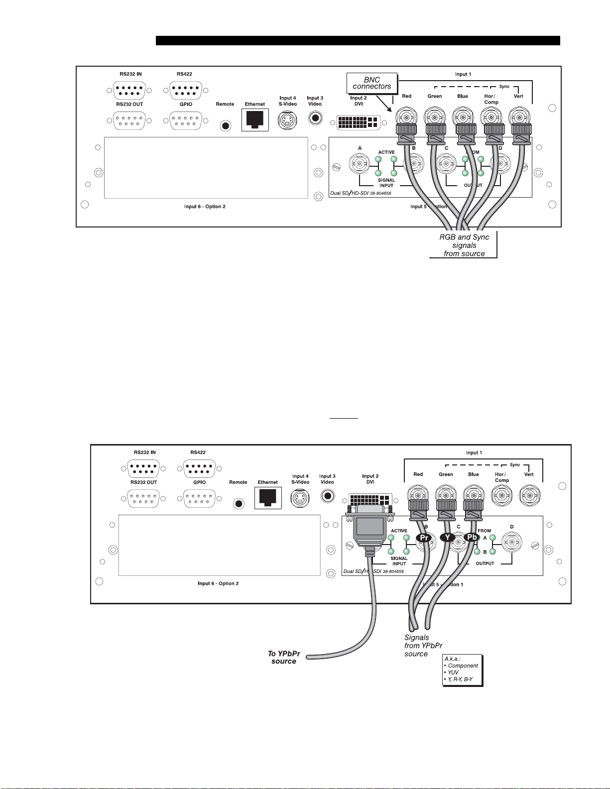
INSTALLATION & SETUP
YPbPr '
(COMPONENT VIDEO)
Figure 2.25. Connecting RGB Input
NOTES: 1) If for some reason the projector fails to recognize a signal as an RGB signal,
specify this Color Space option within the Image Settings menu. See 3.6, Adjusting the
Image. 2) To connect YPbPr signals–such as from DVDs or analog HDTV sources–to
INPUT 1, use the red, green and blue BNCs as described in YPbPr Signals (below)
Connect a YPbPr signal (a.k.a. component video) to
INPUT 1 or INPUT 2 as shown in.
Figure 2.26.
NOTES: 1) If, for some reason, the projector fails to recognize a YPbPr signal,
specify this Color Space option within the Image Settings menu. See 3.6, Adjusting
the Image. 2) Do not connect digital
1 or 2. Use the appropriate digital interface option installed at INPUT 5 or 6.
component signals (known as YCbCr) to INPUT
2-18
Figure 2.26. Connecting YPbPr
Roadster / Mirage S+ User’s Manual
INSTALLATION & SETUP
p
Com
osite Video '
Dual SD/HD-SDI '
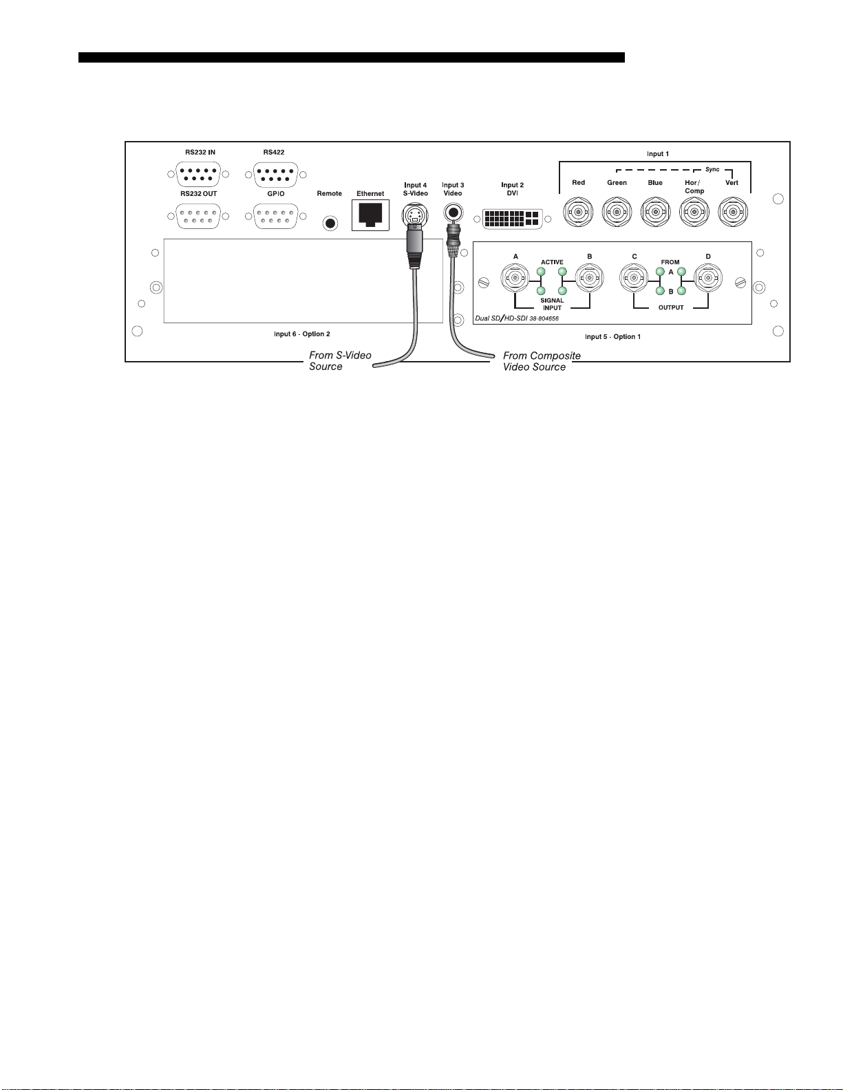
INPUT 3 and INPUT 4 provide simultaneous connection of both a composite video
source (
INPUT 3) and an S-Video source (INPUT 4). See Figure 2.27 below.
Figure 2.27. Connecting Composite Video
Christie’s Dual SD/HD-SDI input module is standard with the Roadster S+ and
factory-installed in
INPUT 5 or INPUT 6. The module’s loop-through capability
enables incoming serial digital data to be tiled across multiple screens, creating vast
“mega resolution” displays. Alternatively, the multiple outputs can be overlapped for
extra-bright displays, or simply distributed to additional projectors for multiple
screens of the same image.
Other Optional Inputs '
The module accepts one or two independent standard- or high-definition serial digital
inputs, decodes them for processing in the main electronics of the projector, and
outputs 10-bit YCbCr 4:2:2 video. Either input can be set as the active primary or
secondary part of a Picture-in-Picture display, and either input can be looped through
to one (or both) of the module’s BNC outputs.
NOTE: Selection of these inputs is described in 3.3, Using the Keypads.
Connect a compatible SMPTE 292M or SMPTE 259M-C source(s) to one or both of
the inputs located on the left side of the module. The module will automatically
detect the standard at each input and configure itself accordingly for correct
termination of the signal. The module also detects and supports dua l link 292M for
SMPTE 372M video standards. For full details, consult the Dual SD/HD-SDI
manual.
Optional modules allow you to increase your total number of inputs and/or
accommodate different signal types, whether analog or digital. Install in the areas
labeled
INPUT 6 or (if available) INPUT 5. Options include:
• RGB 500 Input Module
• RGB 400BA Input Module
• RGB 400 Active Loop Thru Input Module
• Composite/S-Video Input Module
(note: not currently supported)
• PC250 Analog Input Module
• Serial Digital Input Module
• DVI Input Module
• Dual SD/HD-SDI Module
( standard on the Roadster S+ series)
Roadster / Mirage S+ User’s Manual 2-19
INSTALLATION & SETUP
For even more sources, connect a 3rd-party switcher to the RS232 IN port, or, if
RS422-compatible, connect to the RS422 port.
NOTES: 1) Optional digital interfaces cannot be used in a Marquee Case/Power
Supply.2) See Appendix F, Optional Input Modules for a brief description of each
interface.
2.5 Connecting
Communications
Remote Keypads '
Other Controllers '
The most common method of controlling the projector is via one of its keypads. As
an alternative, you may wish to communicate using a PC or similar controller. Such a
device sends commands and receives feedback via serial links (2 types), Ethernet or
GPIO communications to the projector, all described below.
As desired, direct the projector’s IR remote keypad towards the display screen or the
projector’s IR sensors. Alternatively, connect the remote keypad by cable to the
remote phono jack input at the back of the projector.
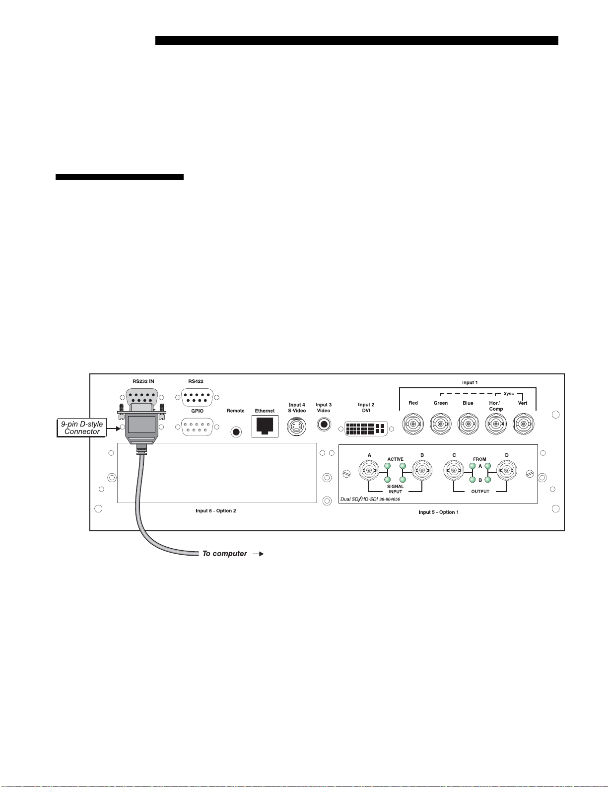
RS232 Serial Communications
From most computers, connect a standard RS232 serial communication cable
between the computer and the projector serial port labeled
RS232 IN—this 9-pin
connector is located on the input panel at the rear of the projector (Figure 2.28). In
the Communications menu, set the projector’s baud rate (default = 115200) to match
that of the computer.
2-20
Figure 2.28. RS232 Serial Communications
Changing the baud rate is done in the projector’s Communications submenu. See 3.7,
Adjusting System Parameters and Advanced Controls.
RS422 Serial Communications
Some computers can provide RS422 serial communications (often through a plug-in
adapter or external converter) rather than the more common RS232 standard. RS422
communication has differential “transmits-and-receives” and is generally better
suited for long distances than is RS232 communication. Note that RS422 is not
compatible with RS232—connecting a RS232-compatible PC to RS422 can damage
the equipment at either end. Consult the documentation provided with your PC if you
are unsure.
Roadster / Mirage S+ User’s Manual
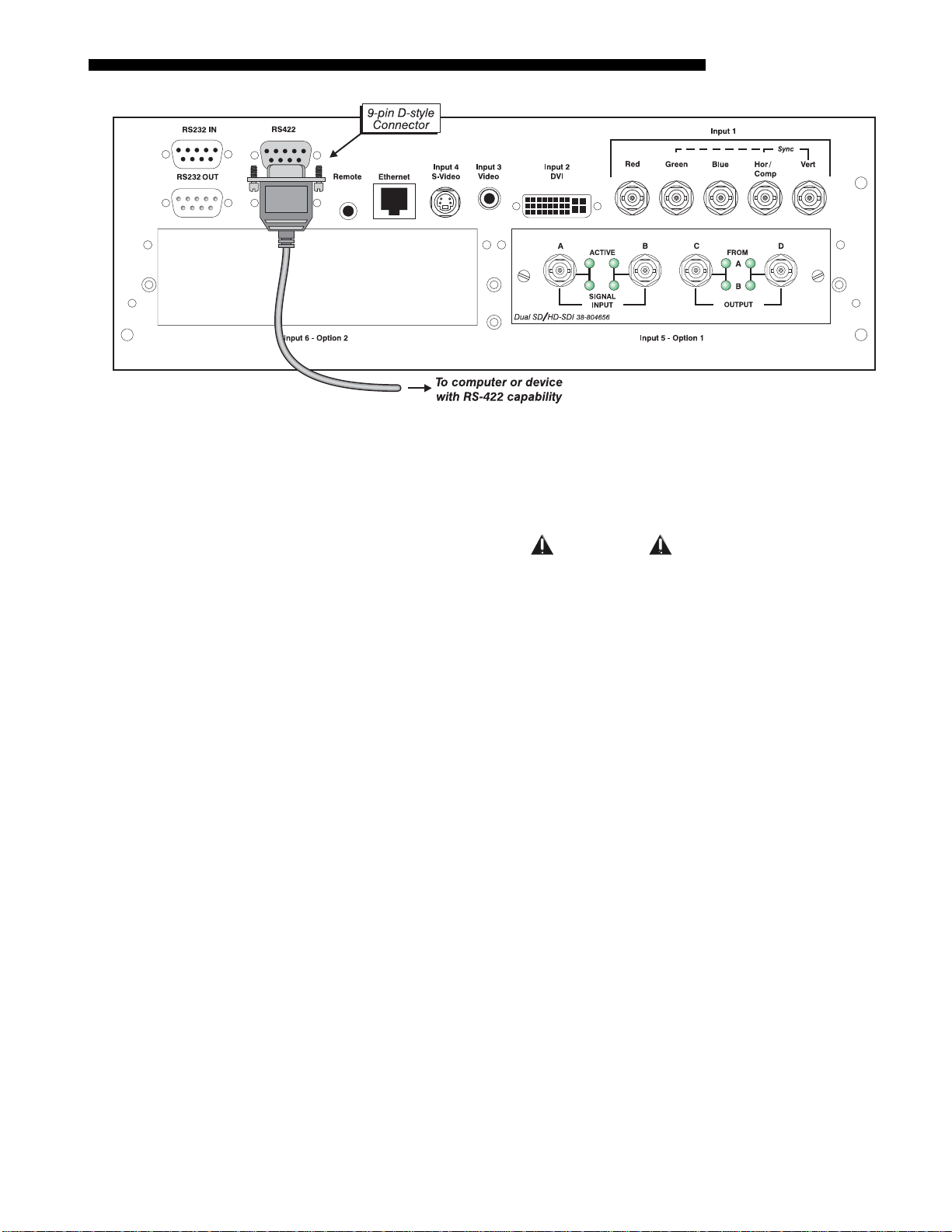
INSTALLATION & SETUP
Figure 2.29. RS422 Connection to a Computer
The nine-pin RS422 connector is located at the rear of the projector (Figure 2.29).
Use this port for communications to and from an RS422-compatible controller. In the
Communications menu, set the baud rate to match that of your RS422 controlling
device.
WARNING
Do not use an RS422 port unless you are using
equipment with RS422 capability. The voltage levels of
this signal can damage incompatible equipment.
Ethernet Communications
To add the projector to an existing Ethernet network with other equipment such as
controllers and other projectors, connect standard CAT5 Ethernet cable between your
Ethernet controller (or hub) and the Ethernet port at the rear of the projector as shown
in Figure 2.30.
CONNECTING TO A PC: If you are connecting the Ethernet port directly to a PC
(rather than a network or hub), make sure to use a crossover Ethernet cable. Keep in
mind that an Ethernet link cannot be used for downloading a software upgrade to the
projector—use RS232.
Roadster / Mirage S+ User’s Manual 2-21
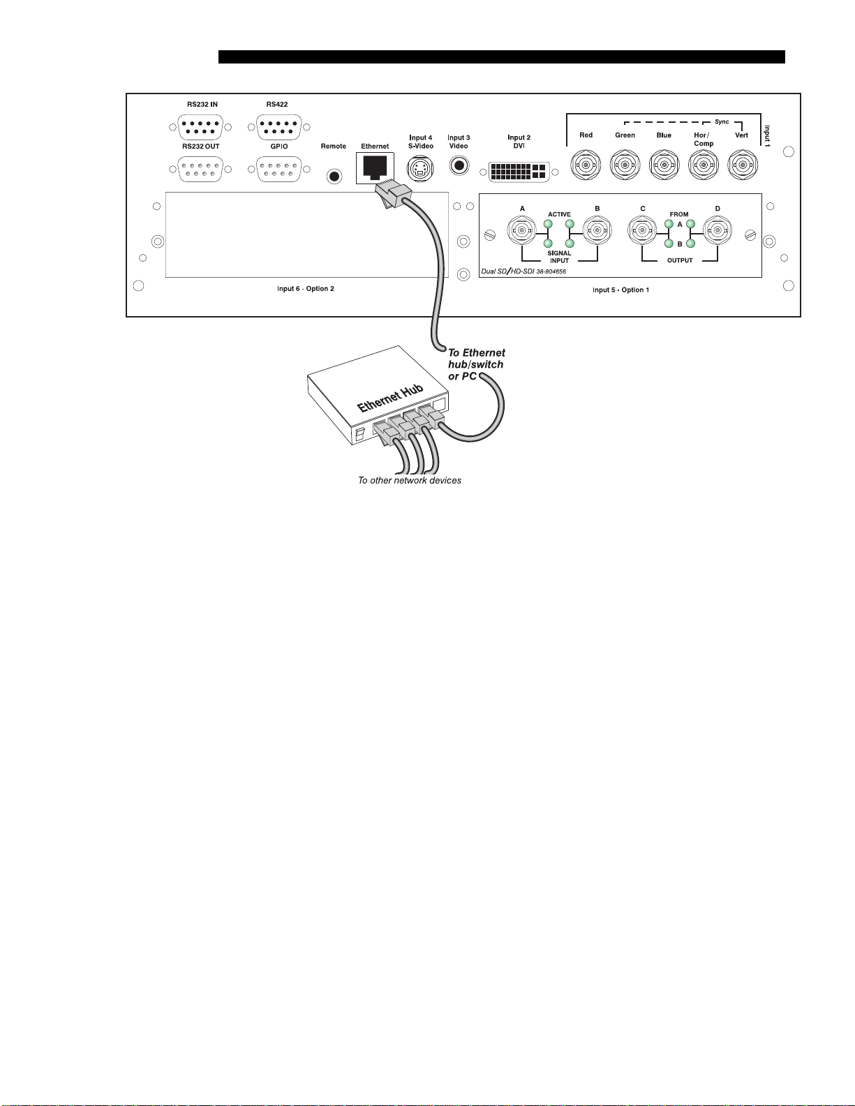
INSTALLATION & SETUP
Figure 2.30. Connecting Ethernet
Upon connection to an Ethernet network, the projector’s factory default IP address of
0.0.0.0 will automatically enable the DHCP function (if available on the network) to
assign a new IP address that is valid and unique for that network. Or, if there is no
DHCP function available on the network (or if a specific static IP address for the
projector is preferred or required), you can set the address in the Ethernet Settings
submenu or via an ASCII serial command.
NOTE: Make sure the projector is connected to the network before attempting to
change its IP address.
Regardless of how it is assigned, once a projector has a valid and unique address it
will respond to commands sent to this address. To determine the projector’s current
IP address, consult the Status or Communications menus.
Refer to 3.7, Adjusting System Parameters and Advanced Controls for further
information about setting up and using a projector connected via Ethernet.
The GPIO Port
The General Purpose In-Out (GPIO) port enables integration of the projector within
an established control system (Figure 2.31). ASCII commands sent via the GPIO link
are stored in projector memory, where they can be triggered as a sequence of events
in the future. See Appendix E.
2-22
Roadster / Mirage S+ User’s Manual
INSTALLATION & SETUP
Figure 2.31. GPIO Port
2.6 Connecting
Multiple
Projectors
Serial Links '
You may wish to chain two or more projectors together so that commands and
communications to and from a controller are relayed to all projectors. Choose a
hardware configuration that best suits your desired communication method.
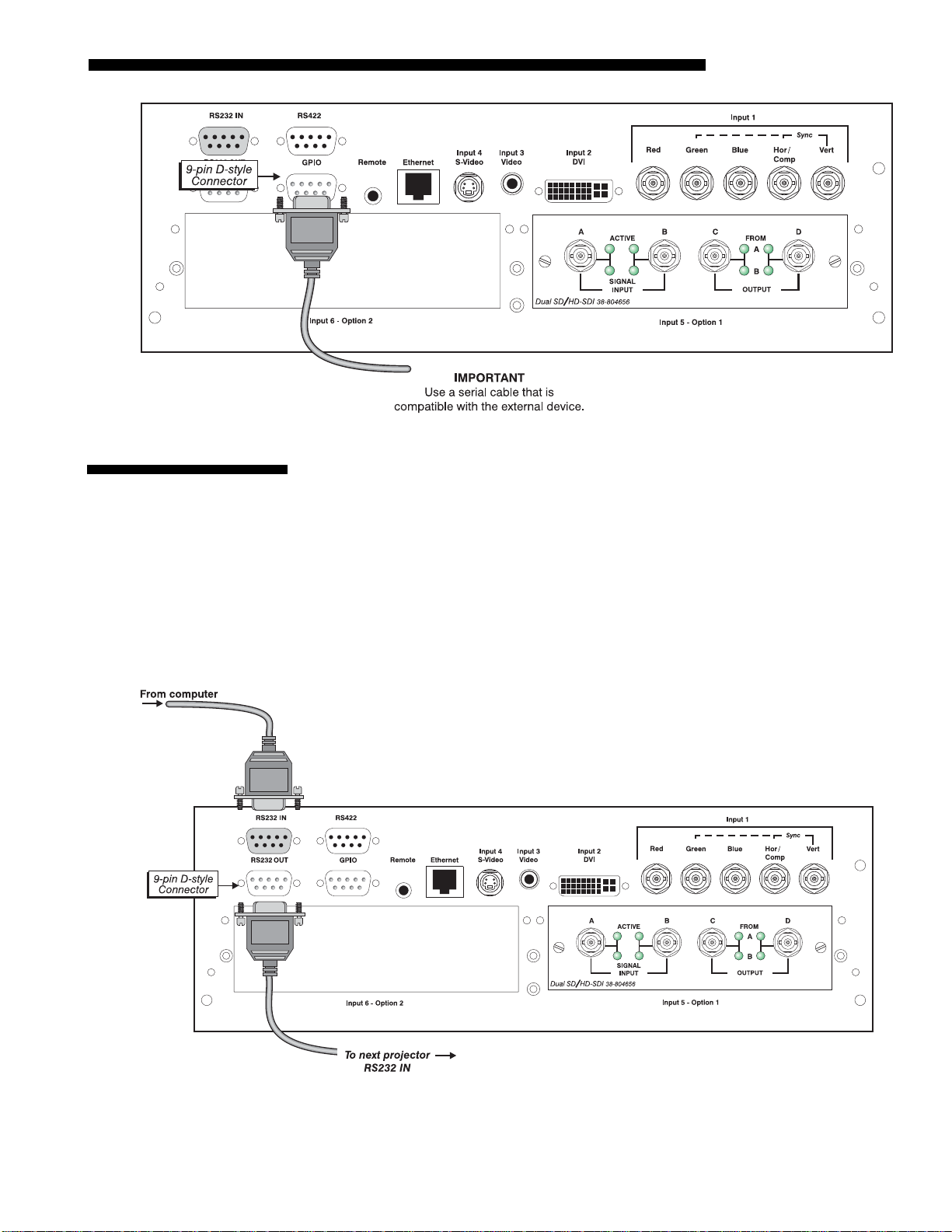
RS232 NETWORK: To control multiple projectors with a computer/controller having
an RS232 interface, first set all projectors to the same baud rate as the controller, then
chain the projectors together by connecting the
projector (already connected to the computer/controller) to the
RS232 OUT connector of the first
RS232 IN connector of
the next projector in the chain. Continue connecting projectors in this manner until
you’ve reached the last projector in the chain, so that only the last projector has an
unused
RS232 OUT port. See Figure 2.32.
Figure 2.32. RS232 Serial Link Loop-Through at First Projector
MIXED NETWORK: To control multiple projectors with a computer/controller having
an RS422 interface, first set them all to the same baud rate as your RS422 controller.
Roadster / Mirage S+ User’s Manual 2-23

INSTALLATION & SETUP
NOTE: You must enable this combination of RS422 and RS232 in the
Communications menu. Set the “Network Routing” option to “RS232 and RS422
Joined”. See Section 3 for details.
Then chain the projectors together by connecting an
(already connected to the computer/controller through the
RS232 port of the first projec tor
RS422 port) to an RS232
port on the next projector in the chain. Continue connecting projectors in this manner
until you’ve reached the last projector in the chain, so that only the last projector has
one unused
RS232 port. See Figure 2.33.
Figure 2.33. Mixed Serial Network
Note that communication parameters such as baud rate must be set to match the
particular controlling device before connecting as a network—refer to the
documentation that came with your controlling device in order to determine the
proper baud rate. See 3.7, Adjusting System Parameters and Advanced Controls if you
need help changing the projector baud rate. In addition, set the Network Routing to
“RS232 and RS422 Joined” if you want to reach all projectors.
Ethernet Networks '
NOTES: 1) To avoid damage, connect only properly wired serial communication
cables. See Appendix C for details. 2) It is recommended that each RS232
communication cable be no more than 25 feet in length. Use high quality cables.
ETHERNET NETWORK SETUP: To add one or more projectors to an Ethernet network,
use standard CAT5 cable to connect each projector’s Ethernet port to a hub on to the
network. A controller or PC must also be connected to the hub. See Figure 2. 34.
Figure 2. 34. Typical Ethernet Network
2-24
Roadster / Mirage S+ User’s Manual

INSTALLATION & SETUP
p
SETTING THE PROJECTOR’S IP ADDRESS: Upon connection to most Ethernet
networks, each projector’s factory default IP address of 0.0.0.0 triggers the network’s
DHCP (Dynamic Host Configuration Protocol) server function to automatically
assign an IP address that is valid and unique for use on that network. Depending on
the network, this DHCP-assigned IP address usually remains stable for a single
session, but may change with subsequent power-ups and logins. On some networks,
the address will remain stable from session to session. In all cases, the projector’s IP
address and port appear in the Status menu as well as the Ethernet Settings submenu.
See Figure 2.35
Figure 2.35. Setting the Projector’s IP Address
Note that if a projector’s IP address is anything other than 0.0.0.0 (shown as
000.000.000.000 in the Ethernet Settings menu) upon connection to an Ethernet
network, or if DHCP is not available on the network, the automatic DHCP server
function for supplying a valid and unique IP address to the projector is disabled.
Instead, a specific and static IP address must be defined in projector memory—enter
the new address in the E the rnet Setti ngs submenu, or send to the projector via a serial
command.. The IP address will be in effect until it is changed again, or until the
DHCP checkbox is re-enabled for use with a DHCP server on the network.
Se
arating Networks '
NOTES: Only the port and IP address of the projector can be changed. The subnet
mask is fixed (255.255.255.0).
CHANGING THE PORT#: On some Ethernet networks, firewall restrictions may
require that the port number of the projector be changed from its default of 3002. If
so, enter a new port number in the Ethernet Settings menu or include the new port# in
an XIP serial command sent to the projector.
By default, communications originating from one type of serial controller—RS232
vs. RS422 vs. Ethernet—stay on the corresponding network path. This separation is
indicated by a “Separate” setting for “Network Routing” in the Communications
menu. If you are using an RS422 controller, for example, it will communicate only
with the projector to which it is connected unless you change this setting to either
“RS232 and RS422 Joined” or “All Joined”(Figure 2.36).
Roadster / Mirage S+ User’s Manual 2-25

INSTALLATION & SETUP
A
To relay all messages to all ports—RS232, RS422, and Ethernet—set the “Network
Communicating to
ll Ports
'
Routing” option in the Communications menu for each projector to “All Join ed”.
This configuration is useful if you are using a non-RS232 controller with the RS232
linking available between these projectors. For example, you may want to use both an
RS422-compatible controller and an Ethernet-connected PC for working with a
network of projectors linked via their RS232 in/out ports (Figure 2.37).
Figure 2.36. Keeping Communications Separate (default)
2.7 Power
Connection
2-26
Roadster / Mirage S+ User’s Manual
Figure 2.37. Joining All Networks
To isolate just RS422 communications, select “RS232 and Ethernet Joined”. In
Figure 2.37, only projector #3 will respond to the RS422 controller. To isolate just
Ethernet communications, select “RS232 and RS422 Joined”—only projector #1 will
respond via Ethernet.
Plug the projector’s high-current line cord into the line input socket located in the
lower right corner of the rear panel of the projector, then plug the 3-pronged end of
the line cord into a grounded AC outlet. Input voltage to all Roadster S+ and Mirage
S+ models must be capable of 200 –240 VAC. Use the proper power source and the
high-current rated line cord provided. See Section 6, Specification s for all power
requirements.
WARNING
Do not attempt operation if the AC supply and cord are
not within the specified voltage and power range.
Caution for Shutdowns: Once the projector is turned off ( ), the lamp
cooling fans will continue to run for approximately five minutes to ensure that the
projector and lamp have sufficiently cooled, at which point the fans will

INSTALLATION & SETUP
automatically shut off. To avoid thermal stress that can lead to premature lamp
failure, never unplug the line cord while the lamp cooling fans are running, and
never unplug to power down.
2.8 Operating
Orientation
2.9 Leveling
The projector is set up at the
factory for use in a front
screen, floor mount
orientation. If your initial
installation is ceiling mount
or rear screen, displayed
images may be upside down
and/or reversed. To correct,
you must change the image
orientation from within the
Configuration Menu(you
may prefer to do this before
physically installing the
projector in its final
position/orientation).
Figure 2.38. Image Orientation
In the Configuration Menu highlight and select the “Image Orientation” pull-down
list. See Figure 2.38 Select from Rear, Inverted Rear, Front or Inverted Front
according to your intended installation. See Section 3, Operation for fu rthe r
information.
For most installations, the lens surface of the projector is parallel to the screen—this
prevents major keystoning of the image (i.e., an image with non-parallel sides). In
addition, the projector must be kept level from side-to-side in order for the lamp to
function safely. To make small corrections to the projector’s level, rotate each leg as
necessary to raise or lower. See Figure 2.39. For angled installations, see “Special
Mounting” under 2.3, Projector Position and Mounting earlier in this section.
2.10 Zoom, Focus &
Lens Offset
Figure 2.39. Adjusting the Feet Height
Once the projector is properly set up and producing an image, you are ready to make
quick lens adjustments. Refer to 3.3, Using the Keypads and 3.4, Navigating the
Menus if you are unfamiliar with using the keypad and menu system.
Lens Adjustments
Note: Not applicable to fixed lenses. Focus fixed lens by turning focus ring on lens.
Roadster / Mirage S+ User’s Manual 2-27

INSTALLATION & SETUP
With the input image displayed:
Zoom
'
o If remote keypad: Press Zoom
o If built-in keypad: Press Zoom
Hold the key down to see the effect –arrows in the display indicate the
direction of the zoom (Figure 2.2).
Focus
With the input image displayed:
o If remote keypad: Press Focus
o If built-in keypad: Press Focus
Hold the key down to see the effect – arrows in the display indicate
the direction of the focus (Figure 2.3).
• LENS OFFSET: To move the image:
•
o If remote keypad: Press either Lens H
Lens V .
o If built-in keypad: Press
keys.
Using the built-in keypad, display the on-screen menu and choose the wired keypad
2.11 Keypad
Conversion
option. Then, connect the remote keypad to the remote phono jack input at the rear of
the projector.
or
or
or
or .
Lens
Shift
and use the arrow
.
.
.
Figure
Figure
2.40
2.41
or
Figure 2.42
2-28
Roadster / Mirage S+ User’s Manual

3.1 Overview
3.2 Projector
Basics
Section 3
Operation
This section explains how to use the projector once it has been installed. Please read
through these pages before using the projector for the first time. An understanding of
projector features and how to access them will help you to take full advantage of the
capabilities of the projector within minutes.
NOTE: Installation involves locating the projector and adjusting it for use at that
location. If you have not yet installed the projector, refer to Section 2, Installation
and Setup.
Most projector functions and adjustments are initiated via keypad commands that
either control the projector directly or activate a system of intuitive menus.
Collections of settings can be defined and retained in the projector’s internal memory
as a custom channel, with up to 50 different channels possible.
Projector components and functions are illustrated below (Figure 3.1). Refer back to
the chart on page 1-2 for additional differences between models.
Components / Features '
Figure 3.1. Basic Projector Components
Zoom
Operated with the keypad, the internal optics of a motorized zoom lens rotates to
adjust the size of the image without moving the projector. Minimum and maximum
image sizes depend on which zoom lens is installed. See Section 5, Specifications.
Lens Release
Push lens release to enable the lens to be rotated for removal.
Roadster / Mirage S+ User’s Manual 3-1

OPERATION
Focus
Operated with the keypad, focus adjusts the sharpness of the image at the current
throw distance.
Lens Offset
Operated with the keypad, vertical and horizontal offsets shift the lens and move the
image up or down and left or right. See Section 2, Installation and Setup and Section
6, Specifications for ranges and other detai ls.
Shutter and Iris
Operated with the keypad, closing the intern al shu tte r block s the lens int ern al ly and
turns the image to off (black). Enlarge the diameter of the iris—a.k.a. optical
aperture—for optimized brightness; reduce the diameter to optimize contrast ratio.
Eyebolts
2 eyebolts on bottom (factory-installed)—for attaching safety cables when hoisting
inverted projectors.
4 eyebolts for top (separate)—for non-inverted hoisting. NOTE: 2 additional
safety eyebolts required.
Handles
For brief hand transport only. Not used for hoisting, rigging, or as safety points.
Stacking Mounts / Stacking Legs
NOTE: Optional on Mirage S
+
.
For stacking up to 3 projectors. See Section 2 for details.
WARNING
Use Christie stacking mounts only.
Adjustable Feet
Turn the 4 adjustable feet to increase or decrease height and/or tilt as needed. For
most installations the projector will likely be slightly inclined to match the screen tilt
– this reduces the amount of vertical offset required. See 2.3, Projector Position and
Mounting
Filter Door
Louvered grille for air intake. Remove to access and replace air filter.
Lamp Door
Louvered/grille for accessing and replacing the lamp module. NOTE: Lamp
replacement requires a qualified service technician.
3-2
Input Panel
The input panel wires the projector to inputs (sources) and controllers such as PCs.
Roadster / Mirage S+ User’s Manual
COMPOSITE/S-VIDEO INPUT - Accepts a composite video, DVI and S-Video
signal from devices such as VCRs.
RGB INPUT - Accepts RGB and sync signals from devices such as computers,
as well as composite video, S-Video or YPbPr component signals.

OPERATION
RS232 SERIAL INTERFACE (WITH LOOP THROUGH) - Allows one or more
projectors to be remotely controlled by a computer or controller,
RS422 INTERFACE - Allows one or more projectors to be remotely controlled by
an RS422 compatible computer or controller (such as the Two-Way Controller
accessory).
AC Power Input and Monitoring
AC LINE CORD INPUT - Use the AC supply specified, and always use the
line cord provided with the projector. See Section 5. Before unplugging, wait until
the main blower turns off or the LCD status reads Power Off.
Model AC Power Specifications
Roadster S+12K 200-240 VAC, 50-60 Hz, max. 15 amps @ 200VAC
Roadster S+16K 200-240 VAC, 50-60 Hz, max. 20 amps @ 200VAC
MirageS+14K 200-240 VAC, 50-60 Hz, max. 20 amps @ 200VAC
WARNING
Do not attempt operation if the AC supply is not within the
specified voltage and power range. Use the specified line cord.
VOLTMETER - Displays incoming voltage level reaching the projector.
SWITCH/BREAKER - The breaker on the rear panel serves two purposes: 1) It is
a power switch for the ballast 2) It protects against excessive AC conditions
(15A or more for Roadster S+12K, and 20A or more for
RoadsterS+16K/Mirage S+14K). If the projector is faulty or excessive AC is
detected, the breaker will “trip” to OFF in order to prevent damage. Try
moving the breaker ON again - if the breaker continues to trip OFF, this
indicates a major fault and the AC problem must be resolved. Possible causes
might include shorts, damage to lamp cables, or excessive AC.
Note: This switch does not power up the projector or start the lamp. You must press
on the keypad.
Two Status Displays:
2-DIGIT STATUS/ERROR CODE WINDOW - This LED (light emitting diode)
display is adjacent to the built-in keypad. During normal operation, the
“Power” light is steady yellow and indicates “on”. When the status of the
projector changes, the LED displays a 2-digit code number representing the
projector’s new status. In addition to the numeric readout, there are two
decimal points in the display: the right decimal point flashes when the projector
receives a command, and the left point flashes when the projector sends a
command.
LCD STATUS DISPLAY WINDOW - Displays a text message describing the
current system status (such as an error). During normal operation, this display
indicates Power On and includes the frequencies of the vertical and horizontal
syncs. The display also shows if the On Screen Display (OSD, or menu system)
is on or off. The LCD displays the message Power Off when the breaker is on
but the lamp is off.
Roadster / Mirage S+ User’s Manual 3-3

OPERATION
3.3 Using the
Keypads
Keypads / Sensors
WIRED REMOTE KEYPAD CONNECTOR - For optional tethered remote control of
the projector.
BUILT-IN KEYPAD - Alternative location for working with the projector.
INFRARED SENSORS - The infrared (IR) sensors on the front and rear of the
projector receive infrared signals from the IR keypad for remote control of
projector functions. For proper operation, make sure that these sensors are not
blocked.
The projector is typically controlled by using one of the following keypads:
• Built-in Keypad at the rear of the projection head
• Remote Keypad for tethered or tetherless control (includes cable for
connecting as a wired remote)
While each of the keypads provides complete control of the projector, they differ
slightly in their arrangement of keys and in which functions can be accessed directly
with a key press rather than requiring use of the menu system. You may find one
keypad more convenient than another for your specific installation and application.
Built-in '
To control the projector
when signals from a
remote keypad cannot
reach the projector, use
the projector’s built-in
keypad (Figure 3.2). Two
nearby status windows
Figure 3.2. Built-in Keypad at Projector Rear
provide feedback
indicating current status and activities of the projector. Because the built-in keypad
has fewer keys than the remote keypad, certain projector functions are accessible
only through the menu system rather than via a direct key.
3-4
Roadster / Mirage S+ User’s Manual

OPERATION
IR Remote
'
Figure 3.3. Remote Keypad
The IR remote keypad controls the projector by way of wireless communications
from a battery-powered infrared (IR) transmitter. Use the IR remote keypad the same
way you would use a remote keypad supplied with a TV or VCR. When making key
presses, direct the keypad either toward the screen or toward the front or rear IR
sensors on the projector.
NOTE: For improved reception, use an optional remote IR sensor to route the signal
via a phone cable plugged into the wired keypad port.
Roadster / Mirage S+ User’s Manual 3-5

OPERATION
yp
Wired Remote
With the addition of a cable (supplied), the IR remote converts into a wired remote
'
keypad. Simply connect to the
remote is recommended when the rear built-in keypad is inaccessible or if lighting
conditions are interfering with IR transmission.
NOTE: Batteries must remain in the remote to use the laser feature.
Guide to Keypads '
1) Press keys one-at-a-time; there are no simultaneous key combinations required.
2) Note that three keys—Power, Shutter and OSD—are “press-and-hold” keys that
do not function with a typical quick press-and-release keypress (see Figure 3.3).
3) Hold arrow keys down for continuous adjustment/movement in one direction. In
serial networks, pause briefly between adjustments to ensure that more distant
projectors can “keep up” with the commands.
4) If you press a key while the projector is still responding to the previous action,
such as during power-up, the second key press may not take effect.
Ke
ad Commands '
Specific keypad commands are explained below:
Power ON/OFF
Press and hold
Or press and release
guarantee the correct toggle (useful if you are unsure of the present state).
NOTES: 1) After powering down, the lamp cooling fan remains on for approximately
5 minutes to cool the lamp. 2) It is a good idea to avoid turning a projector back on
until it has been off for several minutes. Hot re-strikes of the lamp may reduce lamp
life.
REMOTE input at the rear of the projector. The wired
briefly to toggle the projector on or off with a single keystroke.
followed immediately by
(on) or
(off) to
Tes t
Auto
Setup
Test
Press
Tes t
is up, use
Auto
Auto
Setup
Press
to scroll through the projector’s internal test patterns. When a test pattern
to scroll through the patterns without going back to the input.
to initiate an automated process in which the projector optimizes critical
display parameters such as size, position, pixel tracking, etc., for the current unlocked
channel. These parameters are liste d in Table 3.1. An Auto Setup can save time in
perfecting a display, and you can further modify the settings as desired.
Table 3.1. Auto Setup
What an “Auto Setup” Does
OPTIMIZES: SETS TO DEFAULT:
Pixel Tracking Contrast
Pixel Phase Brightness
Size and Blanking Auto Input Level (off)
Vertical Stretch Detail (if video source)
Position Filter
Input Levels Luma Delay
Chan nel
Channel
Chan nel
Press
to select a specific source setup (channel) defined and stored in projector
memory. Once you enter a 2-digit channel number (or, if there is a list displayed,
3-6
Roadster / Mirage S+ User’s Manual

OPERATION
highlight it and press ), the display will automatically change and update
according to the numerous setup parameters defined for that channel. Note that a new
channel is automatically created if you adjust an image from a new source.
NOTE: Channel (
Chan nel
) key behavior during a presentation depends on whether or
not the Display Channel List option is enabled in the Menu Preferences menu. You
can choose to use a scrollable list of channels when you press
Chan nel
, or you may prefer
to enter the desired channel number “blind”, i.e., without on-screen feedback. See
Menu Preferences later in this section.
Input 1
Input 1
Input 1
Press
to display from the data input source connected to BNCs labeled
INPUT 1.
If PIP is enabled, pressing this key will change the PIP source.
Input 2
Input 2
Input 2
Press
to display from the DVI source connected to INPUT 2. If PIP is enabled,
pressing this key will change the PIP source.
Input 3
Input 4
Input 5
Input 3
Input 3
Press
enabled,
to display from the composite video source connected to INPUT 3. If PIP is
pressing this key will change the PIP source.
Input 4
Input 4
Press
enabled,
to display from the S-video source connected to INPUT 4. If PIP is
pressing this key will change the PIP source.
Input 5
Input 5
Press
PIP
to display from the INPUT 5 interface module installed in the Option 1. If
is enabled, pressing this key changes the PIP source. If there are two inputs
connected here, such as if the Dual SD/HD-SDI is installed, the second input (B) is
considered
INPUT 7. Press INPUT 5 to access INPUT 7 as follows:
• While displaying from
INPUT 5, press
Input 5
again. This switches to INPUT 7.
• While displaying from any input other than the Dual SD/HD-SDI Module,
Input 5
press
the Dual SD/HD-SDI Module inputs (A or B) was last used. Press
. This switches to either INPUT 5 or INPUT 7, depending on which of
Input 5
again
to display from the other Dual SD/HD-SDI Module input.
Input 6
Input 6
Input 6
Press
to display from the INPUT 6 interface module installed in the Option 2. If
PIP is enabled, pressing this key changes the PIP source. If there are two inputs
connected here, such as if the Dual SD/HD-SDI is installed, the second input (B) is
considered
INPUT 6 to access INPUT 8as follows:
• While displaying from
INPUT 8. If you are using the built-in keypad or the remote keypad, press
INPUT 6, press
Input 6
again. This switches to INPUT 8.
• While displaying from any input other than the Dual SD/HD-SDI Module,
Input 6
press
Roadster / Mirage S+ User’s Manual 3-7
. This switches to either INPUT 6 or INPUT 8, depending on which of

OPERATION
the Dual SD/HD-SDI Module inputs (A or B) was last used. Press
to display from the other Dual SD/HD-SDI Module input.
Bright
Brightness
Bright
Press
to increase or decrease the amount of black in the image. Use
keys until you reach the desired level of contrast—for best results, start high and
decrease so that dark areas do not become black (i.e., “crushed”). Conversely, overly
high brightness changes black to dark gray, causing washed-out images. See 3.6,
Adjusting the Image (Image Settings subsection). NOTE: Always adjust brightness
before contrast.
Contrast
Contrast
Contrast
Press
to change the amount of white in your images. Use keys until
you reach the desired level of contrast—for best results, start low and increase so that
whites remain bright but are not distorted or tinted, and that light areas do not
become white (i.e., “crushed”). Conversely, low contrast causes dim images. See 3.6,
Adjusting the Image (Image Settings subsection).
Gamma
Gamma
NOTE: This is the same as “Gamma” in the Image Settings Menu. “Gamma”
determines what gray shades are displayed between minimum input (black) and
maximum input (white) for a given amount of signal. The proper setting helps
maintain optimized blacks and whites while ensuring a smooth transition for the “inbetween” values utilized in colors and grays. Thus, unlike brightness and contrast
settings controls, the overall tone of an image can be lightened or darkened without
changing the two extremes, and your images will be more vibrant yet with good
detail in dark areas.
Input 6
again
The normal gamma setting of 2.5 is correct for most signals and conditions. If excess
ambient light washes out the image and it becomes difficult or impossible to see
details in dark areas, lower the gamma setting to compensate. This will improve
contrast ratio while maintaining good details for blacks.
Menu
Menu
Menu
Press
OSD
OSD (On-screen display)
Press
to enter or exit the projector’s menu system.
OSD
to hide the projector’s menu system during use. To see the menus
again, do one of the following:
• Press and hold
• Press and release followed immediately by
• Press
OSD OSD
OSD
briefly
Invisible menus are fully functional, enabling “hidden” access to numbered features
and image adjustments by entering the corresponding sequence of keypresses on the
keypad.
NOTES: 1) With OSD “on”, you can still hide error messages and slidebars by
disabling these options in the Menu Preferences menu. 2) The state of the on-screen
display appears in the LCD window at the rear of the projector.
3-8
Roadster / Mirage S+ User’s Manual

OPERATION
PIP
Press
to enable and disable Picture-in-Picture. PIP enables you to display two
different images simultaneously – typically a smaller “secondary” image within a
large “primary” background. When a menu control or slidebar is present, press
toggle the current function to affect the other image.
NOTE: Disable PIP and Best Switching for Interlaced sources > 35 kHz.
Shutter
Shutter
Press and hold
Shutter
briefly to toggle the internal mechanical shutter blade closed or
open with a single keystroke. Or press and release
(shutter on; closed) or
(useful if you are unsure of the present state). Alternatively, press
from the present on/off state. A closed shutter blanks the display (turns it to black).
Close the shutter to mute all display while maintaining access to projector functions.
Opening the shutter restores the image.
NOTES: 1) The status of the shutter is shown in the LCD display window at the rear
of the projector. 2) The shutter is open upon power-up.
Func
Function Key
IF WITHIN A MENU: Using the
with the appropriate topic elsewhe re in Section 3. For example, press
Channel Setup menu to enable deletion or copying of a channel.
Shutter
followed immediately by
(shutter off; open) to guarantee the correct toggle
Shutter Shutter
Func
for special tasks within the menu system is noted
Func
to toggle
in the
to
IF WITHIN A PRESENTATION: Press
Func
followed by a 2-
digit number to enable a specific color or colors in the
display (see right). For example,
display only red and green data,
Func
64
67
will
will display
Func
all color data. Eliminating one or more colors can help
with certain diagnostics and setups, such as when
accurately overlaying one image on top of another when
stacking projectors.
DEFINING OTHER USES: Through ASCII messaging on a PC, you can also create
special user functions for keys 1 – 5 and 7 – 9 and others. For example,
Func
can be
programmed to trigger RTEs (Real Time Events) or to display custom menus. Refer
to the separate Christie Serial Communications publication.
Proj
Projector
Press
Proj
to access a specific projector within a group of projectors or to confirm if
the local projector is listening. The number in the “Enter Number” window indicates
which projector is currently listening to commands, and will match the projector
number that has been defined in the Menu Preferences menu.
The “Projector” checkbox (read-only) shows whether or not the projector physically
connected to a keypad is listening to commands from that keypad. A checkmark
means that connected projector is listening ; if there is no checkmark, you are
communicating with a different projector.
Roadster / Mirage S+ User’s Manual 3-9

OPERATION
To control a specific projector with the keypad, enter the 3-digit number assigned to
the projector you want to use. If you switch to a projector other than the one you are
currently using, the checkmark will disappear.
To broadcast to multiple linked projectors, press
Proj
and then
Proj
again without
entering a projector number. Keypad commands will then affect all projectors in the
chain.
NOTES: 1) The “Broadcast Keys” option in the Communications menu must be
selected for only one (any) projector in a serial network. The keypad in use must be
OFF (disabled) for the remaining projectors. See also 2.14 Remote Keypad
Protocols and Conversion, and 3.7, Adjusting System Parameters and Advanced
Controls.
Enter
Press
to select a highlighted item, to toggle a checkbox, or to accept a parameter
adjustment and return to the previous menu or image.
Exit
Exit
Press
NOTE:
Exit
to return to the previous level, such as the previous menu.
Exit
does not save changes within text editing boxes (including number
editing of a slidebar value) or within pull-down lists. It acts as a “cancel” in these
cases.
Arrow Keys
Use the
keys to change a slidebar value or to select a different option
within a pull-down list without having to first scroll through options. These keys also
jump to the next page in long menus. See also Editing Text later in Sect ion 3.
Focus,Zoom,Lens H,Lens V
Use the
keys to navigate within a menu, pull-down list or text box. Use in
combination with power, shutter and OSD keys to force the corresponding state. See
details provided on the back of the remote keypad.
Lens Focus, Zoom and Lens H, Lens V
Focus, Zoom, Lens H, Lens V
Use
the lens for optical sharpness, size, and position. Note the
Lens
Shift
NOTE: The
key, when combined with
keypad is the same as using the
and
Lens
Shift
with their corresponding arrow keys to adjust
Zoom
requires a zoom lens.
keys on the built-in
Lens V
and
Lens H
keys on the remote.
Laser
Press
to activate the laser pointer, and direct the rem ot e at the screen to
highlight an area with a light beam (dot). The closer you are to the screen the brighter
the laser beam appears. The laser pointer works best with reduced ambient lighting.
3-10
Roadster / Mirage S+ User’s Manual

3.4 Navigating the
Menus
Most of the controls for the projector are
accessed from within the projector ’s
menu system. There are several groups of
related functions, with each group
selectable from the Main menu as shown
Menu
at right. Press
at any time to display
this Main menu.
OPERATION
On-line Help '
On the remote keypad, either enter the
number corresponding to the function
menu you wish to access, such as
2
the Image Settings menu. Or use the
desired option, then press
. The corresponding function menu or pull-down list
Figure 3. 4. Entering the Menu System
for
keys on any keypad to highlight the
of further options will then appear.
With a function menu displayed, navigate in a similar manner—enter a menu option
number for any numbered option, or use the
option, then press
(Enter). Extra long menus have a scroll bar on the right—use
keys to highlight the desired
the arrow keys to access the remainder of the menu. Locked items or items that do
not pertain to the current action or condition appear dimmed and cannot be selected.
NOTES: 1) If there is no signal present, all source-dependent adjustments are
disabled. 2) After 15 minutes of inactivity, the projector leaves the menu system and
returns to the presentation. 3) The Status menu is read-only.
When finished with a function menu, do one of the following:
• Press
• Press
If at any time you are uncertain what to do next, press
information about the current menu or highlighted option. Press
Exit
to return to the previous screen
Menu
to leave the menu system and return to the presentation
Help
to display summary
Help
again to exit. In
addition, a line of “hint” text is included at the bottom of some menus.
Figure 3.5. Context-sensitive Help
Help
From presentation level, press
necessary within a topic. Press
Roadster / Mirage S+ User’s Manual 3-11
to access general Help Topics. Scroll as
or
Exit
to return to your presentation.
Help

OPERATION
A
If a slidebar, menu, or message is displayed, you have limited time in which to make
Time-outs
'
a keypad entry before the projector returns to presentation level
disappears. These time-outs may vary depending on what is displayed.
Figure 3.6. Accessing General Help Topics
Help
and the graphic
The Global Icon '
Menu options that include this icon apply universally to any incoming signal.
The PIP Icon '
Menu options that include this icon apply to PIP (secondary) images only.
Using Slidebars
nd Other Controls
Most of the function menus allow you to change settings by using slidebars,
'
checkboxes, and pull-down lists. To select a slidebar, toggle a checkbox status, or
view a pull-down list, do one of the following within the function menu:
Enter the menu option number corresponding to the setting you wish to
change (for example, press
1 3
from the main menu
to select Vertical
Stretch in the Size & Position menu).
Or move the highlight to the option desired and press (Enter).
Or move the highlight to the option desired and press to adjust
immediately.
Or bypass the menus entirely and use a single key to immediately access an
adjustment during your presentation NOTE: applies only to options having
their own key, such as Contrast, Brightness, Gamma, etc.
For “blind” access, hide the entire menu system (see OSD key, above)
and/or direct slidebars activated by their own key (such as Contrast,
Brightness, etc.). Control by using the proper keypress or numerical
sequence of key presses.
When using PIP images, use key to adjust the image.
Once selected, change the settings as desired (see below). Changes take effect
immediately and are saved upon exit from all menus, or after 15 minutes.
Slidebars in menus – The current value for a given parameter,
such as size or vertical stretch, appears to the left of its slidebar
icon (adjustment window). This number often expresses a percentage, or it may have
units associated with it (such as pixels, degrees Kelvin, etc.), depending on the
specific option. Press
to gradually adjust the setting up or down—both the
number and the length of the bar change accordingly. Hold for continuous
adjustment. Or press
the keypad, then press
3-12
Roadster / Mirage S+ User’s Manual
to activate a slidebar text box for specific number entry via
to save (or press
Exit
to cancel).

OPERATION
g
“Direct” slidebars - For quick access, you access Gamma, Brightness, and Contrast
slidebars without traveling the menu system. For example, simply press
immediately display the same contrast slidebar accessed with the
Contrast option in
Cont
to
the Image Settings menu.
Use the arrow keys to adjust a direct slidebar, or press
number from the keypad, then
Exit
you are done, press
to return to your presentation.
or or to save (or
and enter a specific
Exit
to cancel). When
NOTES: 1) You can still adjust a direct slidebar as usual if the display is turned off
OSD
(see
or Menu Preferences menu) — the slidebar just won’t be visible. 2) A
direct slidebar disappears if it is not used within 5 seconds.
Checkboxes - Conditions are present if its adjacent checkbox contains a checkmark.
To toggle the checkbox, simply highlight and press
check and
to uncheck. If a checkbox is numbered, simply enter its number to
, or highlight and use to
immediately toggle the checkbox.
Pull-down lists – To see a pull-down list of options available for a given parameter
labeled with a
▼, you can:
• Highlight it and press
(Enter)
• Or enter the menu option number.
Use
noted with a small
or
keys to navigate up and down within the list (the current choice is
'). Press to choose an option from the list, if desired.
Editin
Text '
Figure 3.7. Example of Pull-Down List
NOTES: 1) Press
Exit
2) Press
ACTIVATE THE EDIT WINDOW: To enter or edit text, highlight the desired parameter
while in a pull-down list to cancel any change.
(such as a channel name) and press
or
to jump between pages in an extra long pull down list.
to activate its adjacent edit window. Any
previously entered text is displayed with its first character highlighted in a square
cursor, signifying that this character is ready for editing.
NAVIGATE WITHIN THE EDIT WINDOW: Press to move the cursor forward or
to move the cursor backwards as desired.
Roadster / Mirage S+ User’s Manual 3-13

OPERATION
EDIT A CHARACTER: To edit a highlighted character, use
and
to scroll
through the alphabet, numbers, spaces and
punctuation available. When the charac ter
you need appears, press
to select it—
the cursor will move to the next character of
current text, if present. Note that you can
also enter a number directly from the
keypad—it will be accepted and the cursor
Figure 3.8. Entering Text
To insert a space at the cursor location, press
character (or space), press
PRESS (ENTER) WHEN FINISHED: To accept edits and leave the edit window,
press
(Enter).
Func
will move on.
ADD OR DELETE A CHARACTER OR SPACE:
Func
. To delete a highlighted
.
Editing Numerical Values '
3.5 Using Inputs
and Channels
Exit
NOTE: Press
at any time to cancel changes and return to the previously-defined text.
Enter numbers directly from the keypad in order to specify numbers representing
projectors, channels (source setups), or slots. As each digit is entered, it is displayed
and the cursor moves on. Note that channel numbers are defined with 2 digits—for
example, if you enter only a single digit (such as “7”) for a channel number, the
channel will automatically be defined as “07”. Enter “07” to utilize this channel.
NOTES: 1) Once you enter the first digit, this digit replaces all old digits. 2) If you
press any non-numbered key, the number entered up to that point is accepted and
Exit
updated as the new value. 3) Press
to cancel editing of numerical values.
NOTE: See Section 2, Installation and Setup, for a full explanation of how to
connect sources to the projector.
The projector stores and automatically recalls up to 50 different channels (source
setups) for a variety of inputs. This memory feature allows you to define and
conveniently use a wide variety of customized setups rather than having to repeatedly
re-configure the projector for different presentations. Depending on what you have
defined, each physical source connection (i.e., input at the projector) can have several
different channels associated with it.
Do I Select an Input '
Or a Channel?
3-14
Roadster / Mirage S+ User’s Manual
INPUT – An input is a source physically connected at the projector.
Input 4, Input 5
or
Input 6
describes the source signal according to which input slot it is
connected.
Input 1, Input 2
Input 3
,
,

OPERATION
SWITCH TO AN INPUT IN EITHER ONE OF TWO WAYS – Pressing the appropriate direct
key —
Input 1, Input 2
Input 3, Input 4, Input 5
,
or
Input 6
— is a quick and seamless way to display
from one of the six inputs connected to the projector. Or, if the “Numbers Select
Main Image” option, found in the PIP menu, is to enable, press
number keypad
. With either method, the image will be displayed according to the
numbers 1-6 on the
following:
If it is the first time you have used the source/input (or if you used the input but
did not define a channel by adjusting anything), the projector will recognize the
new input signal based on its frequencies and polarities, and will automatically
display an image according to default settings for such a signal. In general, the
default fills the screen as fully as possible. This and other default image settings
depend on the incoming source.
If you used the source once before and changed a display parameter such as
contrast, V-Position, etc., then a channel was automatically created and still exists
in projector memory (see below).
If more than one channel exists for the input, the im ag e will be displ ay ed
according to the setup parameters for the first channel with matching
characteristics.
If PIP is enabled, an input key changes the PIP (secondary) image only. To switch
the main input, use the keypad number keys with “Numbers Select Main Image”
activated.
NOTES: 1) Inputs 7 and 8 require the Dual SD/HD-SDI module in either of the
projector’s option slots. For their selection, see also 3.3, Using the Keypads. 2)For
more information on Numbers to Select Main Image, see 3.8, Working with PIP or
Seamless Switching.
CHANNEL - A channel is a collection of measurements, locations and settings that
tailor the display of a signal to your specific needs. Since source types and
applications can vary greatly, you will likely want to adjust and define a wide variety
of parameters, such as brightness, contrast, size, etc., in order to customize and
optimize the display from or for a particular source. For example, the display settings
you choose for a VCR source may be very different from those you choose for a high
resolution computer source, or one signal may simply vary from another signal used
previously through the same input location. Once you have adjusted a display
parameter, such as pixel tracking or contrast, all current settings are collectively
stored in the projector’s memory as a unique 2-digit channel, such as
. You can
have numerous distinct channels available for the same input, any of which can be
selected by using the
Chan
key on the keypad followed by the 2-digit channel number.
Roadster / Mirage S+ User’s Manual 3-15

OPERATION
Shown at right is a sample channel list as
would be available from
Chan
. This is typically
called the channel list.
Chan
NOTE: The
key may display a channel list
or not, depending on what you have defined for
“Display Channel List” (see Menu
Preferences later in this section) .
Chan
In order to access channels by using
on
the keypad, you must first create the channels.
See below.
Channel List
Creating a New '
Channel
– AUTOMATIC –
To use a new source with the projector, a new channel must be added to projector
memory so that the projector will respond properly to an input signal from that
source in the future. A new channel can be created automatically, as described here,
or it can be copied from an existing channel and then edited as necessary (see
Copying or Deleting Channels later in this sect ion ).
When you select a direct input (
existing channels are searched for matching input and signal parameters. If no match
to the incoming input signal is found, a new channel is temporarily created based on
factory-defined defaults for this type of signal. The channel number assigned is the
lowest available number from 1-50.
NOTES: 1) An automatic channel will be discarded unless one or more of its
parameters are changed, and will not appear in the channel list (see below). 2) If two
channels have the same distinguishing source chara ct eris t ics exce pt for the rev er sal
of sync connectors (i.e., H-sync and V-sync, are switched), they are still defined as
distinct channels. 3) You cannot define a new channel without an incoming signal.
If the incoming signal does match an existing channel, the image will be set up and
displayed as usual according to the parameters currently defined for that channel.
USING A CHANNEL: You
can normally select a
channel at any time by
pressing
Chan
you want to prevent a
channel from appearing in
this list, you must edit the
channel as described in
Channel Edit later in this
section. Such a channel can still be selected by entering its number as shown at right.
(see right). If
Input 1, Input 2
Input 3, Input 4, Input 5
,
or
Input 6
), the projector’s
3-16
NOTES: 1) The current channel is highlighted upon entering the channel list, or, if
this channel is not displayed here, the first channel in the list is highlighted. 2)
Channels created automatically do not appear in the channel list unless a parameter
for the channel has been changed.
Roadster / Mirage S+ User’s Manual

All available channels are listed in the Channel Setup menu, which describes how
A
What Channels
re Defined So Far?
'
each channel can be accessed and which serves as the gateway for editing, copying
and deleting channels.
From the presentation
level press
display the Main menu.
To display the Channel
Setup menu, press , or
move the highlight to the
Channel Setup option and
press
Setup menu will appear
(see sample at right),
with the active channel highlighted.
WHAT APPEARS IN CHANNEL SETUP MENU? This menu lists all channels defined so
far and indicates where they connect on the projector’s rear input panel. The far left
column lists channel numbers currently defined. The
values in the far right columns indicate horizontal and
vertical frequencies—if a user has defined a name for this
channel, it appears here instead. Remaining columns
contain details pertaining to each channel setup, such as its
switcher number (always 0 = projector), slot location (01-
08), a variety of icons indicating access to each channel, and an abbreviated
description of each signal type. See Editing a Channel Setup for details.
Menu
Enter
. The Channel
OPERATION
to
Figure 3.9. All Channels Appear in the
Channel Setup Menu
NOTE: If you have more than a handful of channels, use
and to see the
remaining channels not visible in the initia l disp lay of channe ls.
SIGNAL TYPE — Either channel list, whether the
Chan
key list or the Channel Setup
menu, identifies signal types in a shortened form as defined below. These descriptors
indicate what signal information the projector uses to identify a match for a given
channel, and are preceded by either an “i” (interlaced signals) or “p” (progressive
signal“). See Table 3.2.
Table 3.2. Abbreviations for Signal Type
Abbrev. Signal Type
4WH Composite (4 wire) on HC input
4WV Composite (4 wire) on V input
SG Sync-on-green
5W Separate H,V
5WR Separate H,V swapped
SVid S-Vid
CVid Composite Video
Dig Digital
FUNCTIONS WITHIN THE CHANNEL SETUP MENU —To copy, delete or edit a channel,
highlight the desired channel in the Channel Setup menu and do one of two things:
• Press
Func
if you want to copy the selected channel or delete this or other
channels. See Copying or Deleting a Channel below.
Roadster / Mirage S+ User’s Manual 3-17

OPERATION
g
• Press
Copying or
Deleting Channels
TO COPY A CHANNEL, highlight the desired channel in the Channel Set up menu, then
'
Func
press
Enter
—a new channel will be created. It is identical to original, which still remains,
but it is identified with the next available number from 01-50. If you change your
mind and do not want to copy the current channel, press
the previous menu. Copying channels is a quick method for creating numerous
channels, each of which can then be edited and adjusted for a variety of presentations
in the future.
Enter
if you want to edit channel setups (i.e., non-image related
parameters) for the selected channel. See Editing a Channel Setup,
below.
to go to the Channel Copy/Delete submenu. Select “Copy” and press
Exit
to cancel and return to
Figure 3.10. Copying A Channel
Editin
a Channel Setup '
TO DELETE A CHANNEL, highlight the desired channel in the Channel Setup menu,
then press
press
Func
to activate the Channel Copy/Delete submenu. Select “Delete” and
Enter
—a confirmation window will appear to make sure that you really want to
delete this channel.
Figure 3.11. Deleting a Channel
TO DELETE MULTIPLE CHANNELS, highlight any channel in the Channel Setup menu
and press
Only” and press
Func
to go to the Channel Copy/Delete submenu. Select “Delete Unlocked
Enter
to delete all unlocked channels. Or select “Delete All Channels”
to delete all channels, even those that are locked. In either case, the current channel
will remain but will be redefined from projector defaults.
NOTE: For any deletion, a confirmation box appears to make sure that you really
want to delete. Select “Cancel” if you don’t want to delete after all.
The basic setups that describe how and where a channel can be accessed are listed in
the Channel Setup menu. These channel setups can be edited at any time in the
Channel Edit submenu.
3-18
Roadster / Mirage S+ User’s Manual

OPERATION
CHANNEL EDIT — STEP 1
CHANNEL EDIT — STEP 2
CHANNEL EDIT — STEP 3
Menu
From the presentation level press
Channel Setup menu, press
and press
Enter
. The Channel Setup menu will appear.
, or move the highlight to the Channel Setup option
to display the main menu. To display the
To edit parameters shown in the Channel Setup menu, select the relevant channel and press
Enter
. The Channel Edit menu will appear similar to the sample shown in Figure 3.12.
Figure 3.12. Channel Edit Menu (SAMPLE)
If desired, review and/or edit the following channel setups in the Channel Edit menu:
CHANNEL NAME: An alpha-numeric label can be defined and/or changed
•
here. Channel names can be up to 12 characters in length.
CHANNEL NUMBER: A 2-digit channel number can be changed here.
•
NOTES: 1) If you enter a channel number that already exists, a dialog
message appears indicating that this number is already in use–assign a
different channel number. 2) You can define 50 channels.
INPUT: 1-8, corresponding to where on the projector’s input panel the
•
source is connected.
IN MENU: If checked (default, except for automatically defined channels
•
with unchanged parameters), this defined channel will then appear in the
Chan
list available when
accessed via
the channel setup menu
key is pressed. If unchecked, the channel must be
Menu
on the keypad or via the Auto
Source function. NOTE: On-screen display of the channel list is an option
that must be set in the Menu Preferences menu.
• AUTO SOURCE: If checked, (default), the projector can automatically
locate this channel when an incoming input signal matches. If not
checked, the projector can locate the selected channel only when it is
Chan
directly selected via
on the keypad—and a change in input signal will
not result in a channel change.
•
LOCKED: If checked, all of the image settings for this channel are disabled.
If unchecked (default), all available image settings can be adjusted as
desired. You cannot use Auto Setup with a locked channel.
PREVIOUS CHANNEL: Select this option to see or change Channel Edit
•
settings for the previous channel in the Channel Setup list.
NEXT CHANNEL: Select this option to see or change Channel Edit settings
•
for the next channel in the Channel Setup list.
Roadster / Mirage S+ User’s Manual 3-19

OPERATION
2
3.6 Adjusting the
Image
Before You Begin '
The most commonly used options for image adjustments are accessed through two
menus: Size and Position (
Menu
) and Image Settings (
Menu
), both of which
appear in the Main menu. From either of these two menus, you can change settings
affecting the image from the current channel by working with the appropriate
Exit
slidebars, checkboxes and pull- down lists.
will return to the previous menu (or to
the presentation, if from the Main menu) and accept any changes you may have
entered. Settings are saved with the current channel.
From your presentation, you can access any of the individual options in these menus
Menu
by pressing
location in the menu system. For example, press
followed by the appropriate two-digit number representing their
Menu
3
to quickly access the
“Gamma” option in the Image Settings menu.
Note that for certain options, you may prefer to use a “direct key” from presentation
level to go directly to a particular option without traveling through the menu system
(note: available for certain display parameters only). For example, press
access the “contrast” slidebar immediately. Press
Exit
to return to your presentation.
Cont
to
NOTES: 1) To hide these “direct” slidebars, disable the” Display Slidebars”
checkbox in the Menu Preferences menu. 2) To hide the entire menu system from
OSD
view, turn off the on-screen display by pressing
Auto
Use Auto Setup (
Setup
)
For a good and efficient first step in perfecting the image, press
.
Auto
Setup
. This initiates
an automated process in which the projector quickly optimizes critical display
parameters for unlocked channels such as size, position, pixel tracking, etc., based on
the type of incoming source data detected. An Auto Setup can save considerable setup
time, and you can still modify the adjustments as desired using menu options
described below.
Size and Position Menu '
In the Size and Position menu, you
can increase or decrease the size of
your main image, change its
proportion (aspect ratio), move the
image to a specific area of the
screen, and refine other related
parameters. Use Size and Position
controls to match the image
precisely to the screen used at the
site.
Refer to “Using Slidebars and
Other Controls” (earlier in this section) if you need help using any of the options and
controls. Changes made in the Size and Position menu are applied immediately and
are saved when you exit the menu (press
Exit
or
Menu
).
3-20
Roadster / Mirage S+ User’s Manual

OPERATION
Resize Presets
S elect a Resize Presets option
to quickly display an image in
its native resolution or to
automatically resize an image
to closely fill the projector’s
native resolution of 1400 x
1050, or to optimize the width
or height of your display. Size,
Position and Blanking
parameters will automatically
adjust accordingly. Or, if Blanking is set first, which defines an Active Input Area,
Resize Preset scaling will occur in this region of interest only. Resizing options are
explained in detail below.
WHAT IS THE RESIZING DEFAULT? By default when displaying a new source, your
image will utilize as much of the projector’s display area (1400 x 1050) as possible
for the type of incoming source data. See Select “Default” below.
WHEN “CUSTOM” APPEARS: The “Custom” re-size descriptor automatically appears
in the Size and Position menu when any of the values for Size, Vertical Stretch, H-
Position, V-Position or Blanking do not correspond to those for a preset. It is not a
choice in the Resize Presets pull-down list.
• Select
“DEFAULT” for most sources (factory default). The image will be centered
and displayed as large as possible depending on the type of source, as described
below:
A 5:4 graphic image will enlarge to fill the screen height, and be
centered between narrow black side bars.
A video image or 4:3 graphic image will enlarge to fill the screen width.
An HDTV (16:9) image will fill the width and be centered between
black bars on top and bottom.
• Select
“NO RESIZING” to display the image in its native resolution, which may be
smaller than the projector’s 1400 x 1050 resolution. For example, for a source with
a native resolution of 800 x 600, “No Resizing” will center a small image within a
black border—the black border areas are unused areas. See below.
Roadster / Mirage S+ User’s Manual 3-21

OPERATION
• Select “FULL SCREEN” to use all
pixels (1400 x 1050) for
displaying the image, regardless
of source or original aspect
ratio. Incoming source material
having a different aspect ratio
than the projector will be
stretched for display.
• Select
“FULL WIDTH” to fill the
projector’s display from left-toright without changing the original
aspect ratio of the image.
Depending on the source, data at
the top and bottom may be
discarded (cropped), or the display
may have black borders at the top
and bottom (called “letterboxed”).
• Select
“FULL HEIGHT”
to fill the display from
top-to-bottom.
Depending on the
source, this may
create borders.
• Select
“ANAMORPHIC” to display an anamorphic image
in its native 16:9 aspect ratio. The image will fill the
screen from side-to-side, and be centered between
narrow black bars on top and bottom. This is used for
DVD players that output widescreen images compressed
into 4:3 NTSC format.
Size
“Size” controls both the image width and height in tandem, maintaining the current
aspect ratio (proportion) of the displayed signal data.
3-22
Vertical Stretch
“Vertical Stretch” adjusts the height of the image while keeping the width constant.
Use “Vertical Stretch” to change the aspect ratio of the display.
Pixel Track
Steady flickering or several soft vertical stripes or bands across the entire image
indicates poor pixel tracking. Proper pixel tracking helps ensure that the image
quality is consistent across the screen, that aspect ratio is maintained, and that pixel
phase can be optimized (described below). Tracking determines the frequency of the
pixel sampling clock, indicated by the number of incoming pixels per line, so that all
pixels generated by a particular source are sampled.
NOTE: By default, the projector samples at the correct frequency for most sources.
Roadster / Mirage S+ User’s Manual

OPERATION
For best results, use a good test pattern such as a smooth gray consisting of a clear
pattern of black and white pixels, or a similar “half on, half off” graphic image, such
as the Windows 2000 shutdown screen. Adjust the slidebar until the vertical stripes
broaden to the point where one large stripe fills the image. If the image still exhibits
some shimmer or noise, adjust Pixel Phase (below).
Pixel Phase
NOTE: Adjust “Pixel Phase” after “Pixel Tracking”.
Adjust pixel phase when the image (usually from an RGB source) still shows
shimmer or “noise” after pixel tracking is optimized. Pixel phase adjusts the phase of
the pixel sampling clock relative to the incoming signal.
For best results, use a good test pattern such as a smooth gray consisting of a clear
pattern of black and white pixels, or a similar “half on, half off” graphic image, such
as the Windows 2000 shutdown screen. Adjust the slidebar until the image stabilizes
and each pixel is clearly defined. You may notice that you can stabilize the image at
more than one point—i.e., you may find that the image appearance at “11” is
identical to the image appearance at “38”, thus you can use either setting.
If some shimmer from a video or HDTV source persists, use the “Filter” control to
remove high-frequency noise from the signal.
H-Position
This option moves the image right or left within the area of available pixels.
NOTE: The value shown represents where the approximate center of the image lies in
relation to the total number of pixels available horizontally. This varies widely
according to the signal—watch the image while adjusting.
V-Position
This option moves the image up or down within the area of available pixels.
NOTE: The value shown represents where the approximate center of the image lies in
relation to the total number of pixels available vertically. This varies widely
according to the signal—watch the image while adjusting.
Advanced Size and Position
— SUBMENU
This submenu consists of the
following options:
ACTIVE INPUT WINDOW: This
read-only value indicates the
current size (i.e., area) of your
displayed data or “region of
interest” as defined by the
blanking controls. By default, the
projector automatically determines what portion of its full resolution to use, and
pixels in the surrounding borders are turned off. You can also specify a specific
active input window size by adjusting one or more “Blank” settings. For example, if
you have blanked (cropped) 100 pixels from both the left and right edges of an
incoming source of 1400 x 1050, the remaining active input window will be reduced
Roadster / Mirage S+ User’s Manual 3-23

OPERATION
to 1200 x 1050. When using SD or HD or a decoded video source at INPUT 3 or
INPUT 4, the default blanking of “0” defines an active input window of 720 x 483.
BLANKING (TOP, BOTTOM, LEFT, and RIGHT):
Crop the image as desired so that unwanted
edges are removed from the display (changed
to black—see right). Blanking defines the
size of the Active Input Window , or area of
interest. Range of adjustment depends on the
source resolution and other factors. After
adjustment of blanking it may be necessary
to perform a source switch.
NOTE: Blanking a PIP image resembles
zoom (Figure 3.14). For example, left
Blanking zooms the right side of the PIP
image; Right Blanking zooms the left side.
There are no black bars.
Figure 3.13. Blanking of a Primary
Image
3-24
PLUG & DISPLAY (EDID): By default, a Plug & Play
(EDID) source outputs a signal according to the EDID
information provided by the projector. To override this
information and display in a different format (for
example, if your Plug & Play [EDID] device does not
support the projector’s resolution and/or frequency),
select the desired Plug & Play (EDID) resolution from
the list.
Any daisy-chained projectors will also display
according to the chosen Plug & Play (EDID) format.
EDID = Extended Display Identification Data standard.
Roadster / Mirage S+ User’s Manual
Figure 3.14. Blanking of a PIP Image

OPERATION
g
Ima
e Settings Menu '
Use options in the Image
Settings menu to alter your
main image without affecting
its size or position. Changes
made to the Image Settings
menu are applied
immediately and are saved
when you exit the menu
(press
Exit
or
Menu
). Options
not available for the projector
model or source are disabled
and appear dim (gray).
Contrast
(
SHORT CUT: Press
Contrast
and adjust the slidebar.)
“Contrast” increases or decreases the perceived difference between light and dark
areas of the image (0-100). For best results, keep close to 50. If contrast is set too
high, the light parts of the image lose detail and clarity. If set too low, the light areas
will not be as bright as they could be and the overall image will be dim. For best
results, start with a low value and increase so that whites remain bright but are not
distorted or tinted, and that light areas do not become white (i.e., are “crushed”).
NOTE: If the environment lighting changes, an adjustment of Gamma is
recommended (see below).
Brightness
(
SHORT CUT: Press
Bright
and adjust the slidebar.)
“Brightness” increases or decreases the amount of black in the image (0-100). For
best results, keep close to 50. Start with a high value and decrease so that dark areas
do not become black (i.e., are “crushed”). Conversely , hig h brightness changes black
to dark gray, causing washed-out images.
NOTE: Brightness should be adjusted before contrast, as Brightness setting affects
the contrast setting.
Gamma
(
SHORT CUT: Press
Gamma
and adjust the slidebar.)
“Gamma” is a global setting that determines what gray shades are displayed between
minimum input (black) and maximum input (white) for all signals. A good gamma
setting helps to optimize blacks and whites while ensuring smooth transitions for the
“in-between” values utilized in other colors.
Thus, unlike “Brightness” and “Contrast”
controls, the overall tone of your images can
be lightened or darkened without changing
the extremes, and all images will be more
vibrant while still showing good detail in
dark areas.
Gamma is used to fine tune the gamma table currently in use, ranging from 1 – 3 (2.5
= default). If excess ambient light washes out the image and it becomes difficult or
Roadster / Mirage S+ User’s Manual 3-25

OPERATION
impossible to see details in dark areas, lower the gamma setting to compensate. This
will improve contrast while maintaining good details for blacks. Conversely, if the
image is washed out and unnatural, with excessive detail in black areas, increase the
setting. In high ambient light conditions, lower gamma may produce better results
than higher gamma. Gamma of 2.5 (default) indicates the gamma table has not been
adjusted. For more information, refer to Advanced Image Settings, Gamma Table
submenu. Again, good gamma improves contrast while maintaining good details for
blacks.
Filter
The proper filter setting is automatically set for virtually all
signals, and rarely needs to be changed. It applies a low pass
filter for noise reduction in the incoming input signal,
particularly for HDTV or SDTV. Applied in the analog domain
before sampling, this filtering removes high frequencies and thus
reduces pixel phase noise (note this also reduces signal bandwidth). Override only if
standard pixel tracking and phase adjustments do not adequately clear up a “noisy”
video signal, or if a graphics signal appears overly “soft”. Both instances indicate that
“Filter” may be set to the wrong option.
Detail
“Detail” adjusts the sharpness of a video image so that edges remain clearly defined.
It can be particularly useful if a significant “Noise Reduction” adjustment has caused
the image to appear too soft. Adjust until the display is as sharp as desired, keeping in
mind that because “Detail” adds some high frequencies back into the image, it can
also re-introduce a certain degree of noise.
Noise Reduction
“Noise Reduction” is similar to the “Filter” control, but operates in the post-sampling
digital domain with a more subtle effect. Higher settings are most useful for clearing
up noisy RGB images such as those from a PC. Adjust as desired, keeping in mind
that reducing noise (which reduces high frequencies) may also soften the image.
Color Space
“Color Space” determines how the color components of an
analog input signal are decoded for accurate color in the display.
Selecting a color space option is useful only for analog signals
and certain digital sources connected to
5
or INPUT 6. Although color space for these analog signals is
INPUT 1, INPUT 2, INPUT
automatically determined by the projector, in some circumstances you may wish to
override this and manually set a specific color space.
NOTE: For many digital signals or for signals connected to
INPUT 3 or INPUT 4, the
color space function is entirely automatic and the pull-down list disabled.
The current color space appears in the Image Settings menu. Press
to select a
different option:
• Select
• Select
RGB unless you are using component video at INPUT 1, 2, 5 or 6.
YPbPr (Video) with a standard definition televised signal (SDTV).
• Select YPbPr (HDTV) with a high definition televised signal (HDTV).
3-26
Roadster / Mirage S+ User’s Manual

OPERATION
NOTE: When certain RGB signals are first connected, the projector may not initially
recognize them as RGB and will incorrectly decode their color information as YPbPr
(video). These signals can include:
• RGB signals in NTSC, PAL, SECAM frequency ranges
• Scan-doubled sync-on-green.
• Scan-quadrupled sync-on-green.
For these signals, change the Color Space to RGB, then define a new channel for
future use.
Video Options
— SUBMENU
This submenu is used with video
sources only (
ENABLE DECODER AGC: Automatic
INPUTS 3 or 4).
Gain Control (AGC) affects decoded
video images only. Enter a checkmark
(default) in most instances— th is
activates the decoder’s AGC circuit to
ensure properly bright images. Delete
the checkmark if a decoded video image exhibits strange color artifacts such as
stripes in highly saturated colors, indicating an incompatibility between this source
and the AGC.
VIDEO STANDARD: For all but the more unusual video standards
available in the world, the projector automatically detects the
incoming horizontal and vertical frequencies and sets the
projector’s processing of this signal to the corresponding standard.
The current video standard name appears in the V ideo Option s
submenu, and includes an “A” if it has been auto-detected. Press
to view or select a different video standard from those
available to the projector—any that are disabled have frequency
characteristics that differ from those of the incoming signal.
Selecting a specific standar d forces the pro jector to process the signal according to
this standard.
NOTE: Best results are obtained with defined channels. Otherwise, switching from
one video source to another can sometimes cause slight disturbances in the display,
indicating that the Auto function is struggling. Recover by briefly selecting a different
video standard, then going back.
Table 3.3. Regions and Video Standards: Summary
Standard Where Used (SUBJECT-TO-CHANGE)
NTSC N. America and Japan
NTSC 4.43 A tape-only standard for partially-translated hybrid signals
PAL Most of Europe, China, Australia, some of S. America, some of Africa
PAL-M Brazil
PAL-NC Argentina, Chile, other Latin American countries
PAL 60
SECAM France, Eastern Europe, most of Africa
Roadster / Mirage S+ User’s Manual 3-27

OPERATION
NOTE: Generally, use “Auto” for all instances EXCEPT: 1) a poor quality input
signal or 2) a black-and-white video signal. In order to detect and display such
signals, select the relevant standard from the lis t.
INPUT VIDEO BLACK: This control
compensates for incoming elevated black
levels present in certain video signals, and
ensures that blacks in the display are
neither crushed (i.e., where dark grays appear black) nor excessiv ely elev ated (i.e.,
where blacks appear dark gray). By default, the pro jecto r automatically determines the
best setting according to the type of incoming video signal:
0 IRE – Used for DVD output with “enhanced black”, SECAM, most
•
PAL standards, and Japanese NTSC.
7.5 IRE – Used for most NTSC video signals.
•
For some types of video, you can override the setting. The control is disab led for ot her
types of video (and all graphics sources). Generally, if black appears crushed when
brightness = 50, choose “0 IRE”. If black appears excessively elev ated, use “7.5 IRE”.
COLOR: This slidebar adjusts the colo r satu rat ion lev el, i.e. the amount of color in a
video image. Lower settings produce less saturated colors — for example a setting of
“0” produces a black and white image. If the color level is too high, colors will be
overpowering and unrealistic.
TINT: This slidebar adjusts the red/green color hue for true color reproduction of
video and HDTV signals connected to Input 3 or 4. For best results, adjust tint while
displaying an external test pattern—otherwise, it is recom m ended that tin t rem a in at
its default setting.
DECODER LUMA DELAY: This control affects any incoming composite or S-video
signal, delaying the luma signal (intensity) in relation to the chroma (color). In the
image, increasing the luma delay will move luma (seen as a shadow where colors
overlap) to the right slightly, with colors remaining in place. Decreasing this delay
will move the shadow slightly to the left. If necessary for your current source, adjust
so that no shadows occur with adjacent colors.
Input Levels
— SUBMENU
NOTES: 1) Because the projector automatically optimizes input levels for all but the
most unusual of sources, it is recommended that only experienced users use the Input
Levels submenu. 2) Before beginning, check that overall contrast and brightness
settings are near 50 and that color temperature is properly set up on an internal
grayscale test pattern. 3) There must be at least 2 consecutive white pixels present in
the image for proper “Auto Input Level” function. Leave this control off after use.
3-28
Roadster / Mirage S+ User’s Manual

OPERATION
Good RGB or input
levels—that is, the drives
and blacklevels for each of
the three colors, red, green
and blue—ensure that
images from analog sources
other than decoded video
have maximum contrast
without crushing black or
white. By default (and in an
“Auto Setup”), the projector
automatically determines
the best input levels by
monitoring image content and adjusting the controls appropriately—further
adjustment is typically not required to obtain proper blacks or whites. NOTE: This
automatic adjustment requires at least 6-12 consecutive white pixels in the image.
Without these pixels, input levels may produce skewed colors, particularly in nonvideo images.
However, for a very unusual source exhibiting one or more overly high blacklevels
(typically caused by a noisy source causing blacklevel spikes), an experienced user
may prefer to use the Input Levels menu (shown above). These adjustments, which
together serve as a calibration process compensating for differences in sources and
cabling, enable an experienced user to perfect the source image input levels and
eliminate the “overshoot” and “undershoot”. Note that Input Levels are of limited use
with digital signals, but do offer some ability to tweak poorly mastered source
materials.
NOTES: 1) Input levels apply for the current source only, but for any color
temperature used. 2) Assuming that color temperature has been set up based on the
internal test patterns, you can then set up input levels for a given source so that it
matches the color temperature of the internal test patterns.
AUTO INPUT LEVEL – Temporarily enter a checkmark only if you are an experienced
user and you have an unusual source that you feel needs further color temperature
and/or input level adjustment. This compensates for incoming out-of-range drives
(white) and blacklevels (black) that would cause “crushing” of light and dark colors
in the image. After entering a checkmark, wait for the six slidebar values to stabilize,
then delete the checkmark and exit. The Auto Input Level is automatically turned off
upon exit from the Input levels Menu.
BLACKLEVELS AND DRIVES – To check your image levels and adjust these controls:
1. Make sure overall “Contrast” and “Brightness” settings are both set to
near 50. NOTE: Not required for “Auto” adjustment.
Contrast
•
•
= 50 (approx.)
Bright
= 50 (approx.)
2. Check the color temperature setup using an internal grayscale test
pattern, making sure to obtain a neutral grayscale. NOTE: Not required
for “Auto” adjustment.
Roadster / Mirage S+ User’s Manual 3-29

OPERATION
3. Confirm that you are using an analog source not connected to INPUT 3 or
INPUT 4, as Input Levels are not applicable for digital sources or sources
going through the decoder. A grayscale is recommended.
4. If the blacks and/or whites appear OK, input levels do not need
adjustment. If black levels are too high (and/or whi tes are too low, which
is rare), you likely have a noisy source that is producing skewed input
levels. Continue with Step 5.
5. Temporarily enable “Auto” in the Input Levels submenu. Wait for all 6
values to stabilize. Alternatively, do not use “Auto”—reduce blacklevels
manually instead. Judge by eye and change one or more of the six levels
as necessary to obtain proper blacks and whites. You may want to see
only a certain color while adjusting—use the “Color Enable” option
(described below).
6. Delete the “Auto” checkmark and leave the Input Levels menu.
IMPORTANT: Do not use Input Levels to adjust color temperature. This will
distort Contrast and Brightness functions as well as color temperature.
AUTO COLOR ENABLE – When a checkmark is present, selecting a specific blacklevel
or drive to adjust will automatically enable the corresponding color in the display.
Delete the checkmark to see all colors, or to enable a different specific color through
the Color Enable Control.
CLAMP LOCATION – This option (formerly known as sync tip
clamping) can brighten the image produced from certain hig h-
resolution high-frequency graphic sources. For almo st all source s,
the best clamp location is automatically selected by the projector.
Use the normal Back Porch location if the im ag e is eithe r suffic iently brig ht or overly
bright. Select Sync Tip if the image appears unusually dim , if there are ho riz ontal
streaks across the image, or if there is sig nifi cant colo r d rift. This moves the clamping
pulse from the normal backporch location (which is likely too short) to the tip of the
horizontal sync pulse. Tri Level is typical ly needed for an HD TV source.
COLOR ENABLE – Select which color or colors you want to see in the display, useful
while working with color temperature white levels or input levels.
PEAK DETECTOR – The Peak Detector is a tool to assist with defining individual input
levels, enabling you to accurately set the Input Levels for any particular source with
the appropriate image. Enabling the Peak Detector activates a special operating mode
for detecting only pixels that are considered black or white—all other levels are
displayed as a mid-level gray. When used with a smooth grayscale pattern in which
black and white are known to be at opposite edges of the image, you can watch these
isolated areas while adjusting individual blacklevels and input drives until both black
and white edges are just visible and distinguished from neighboring pixels. Images
from this source will then display correct blacks and whites without crushing.
See Figure 3.15. Adjusting Input Levels Using the Peak Detector
:
3-30
1. Display a 16 level grayscale test pattern from the desired external source, and
enter a checkmark in the Peak Detector checkbox. NOTE: The “Peak
Detector” will initially render the grayscale as a uniform gray field before
adjustment or extreme crushing.
Roadster / Mirage S+ User’s Manual

OPERATION
2. Display one primary color. NOTE: Selecting Auto Color Enable ensures the
correct color is displayed for each setting.
3. For the current color, adjust its corresponding “Blacklevel” slidebar just until
a single band of black appears at one edge of the screen. This band represents
the first band of the grayscale pattern, which should be 100% black. Do not
adjust too far.
4. With the same color still active, adjust its corresponding “Input Drive”
slidebar just until a single band of color appea rs at the oppos ite edg e of the
screen. This band represents the last band of the grayscale pattern, which
should be 100% white (or the current color, if a certain color is enabled). Do
not adjust too far.
5. It may be advantageous to go back and check the black band—adjust the
blacklevel slidebar if nece s sary . NOTE: Readjusting blacklevels at this point
affects the gain; only readjust when absolutely necessary.
6. Repeat Steps 3-5 with the other two remaining primary colors. When each
primary color shows one optimized black band and white (or colored) band,
the input levels for this source are correctly set. Upon exiting the Input
Levels menu, the Peak Detector checkbox will clear.
Figure 3.15. Adjusting Input Levels Using the Peak Detector
Advanced Image Settings
— SUBMENU
Use the Advanced Image
Settings submenu to make the
adjustments necessary for lesser
used but more specialized
applications on your projector.
(RED EXAMPLE SHOWN)
Roadster / Mirage S+ User’s Manual 3-31

OPERATION
GAMMA TABLE: This control applies a default video or graphics gamma table or
“curve” to your images, controlling the intensity of midlevel colors and producing
maximum contrast, brightness and color
performance. As shown at right, the
graphics curve is a simple power curve
while the video curve has a linear segment
near black to compensate for increased
blacklevels typical of video signals.
Although the projector automatically
applies either the graphics or video curve
according to what type of incoming signal is detected, in some cases you may wish to
override this default and use graphics gamma for a video source or video gamma for
a graphics source. Alternatively, if neither default is ideal, you may prefer to apply a
user-defined custom gamma curve that has been created externally, named, and
downloaded to the projector (requires separate PC-based Arbitrary Gamma
KoRE Librarian
software applications). If any of these special user curves have been
and
installed, their names will appear in the Gamma Table pull-down list.
Keep in mind that any Gamma Table choice sets the related Gamma value (shown in
the Image Settings menu) to a 2.5 default, where it can be fine-tuned as desired.
Different values (1-3) here indicate that the original gamma table has been adjusted
with either the Gamma slidebar or direct key.
SELECT COLOR ADJUSTMENT: In “Select Color
Adjustment”, choose an overall color palette for all images.
The “Max Drives” factory default simply drives all 3 colors
at their maximum level so that they are fully on and cannot
be changed. The two other pre-defined color adjustm ent
choices—SD Video and HD Video—apply a color gamut
optimized for video sources (standard or high-definition).
Alternatively, you can specify a color temperature. This
enables the adjacent Color Tempera ture slidebar and applies
its current setting (default = 6500K). If none of the pre-defined “Select Color
Adjustment” options or color temperatures suit your application, select one of four
color gamuts previously defined by a user (User 1, 2, 3, 4). A “User” option applies a
customized color performance in which the user has precisely set the hue and
intensity of each color component in the Color Adjustment by X/Y or Color
Saturation submenus. It is most often needed with multiple-projector applications.
Select the color adjustment producing the best color accuracy for your application
and installation.
To configure a “User” color adjustment (gamut), use either the Color Adjustment by
X/Y or Color Saturation submenu.
NOTES: 1) “Color Temperature” defaults to 6500K until changed. All four “User”
options default to SD Video unless they have been redefined by the user. 2) Factorydefined color primaries, which ensure consistent color gamut from projector-toprojector, can be calibrated in the Service menu only. If you suspect alteration, the
factory settings can be recovered with selection of Reset to Factory Defaults? in the
Color Primary Settings submenu within the Service menu (password-protected).
3-32
COLOR TEMPERATURE — Adjust to apply a specific and accurate color temperature
to all displays. Color temperatures are expressed in degrees Kelvin (3200-9300K),
Roadster / Mirage S+ User’s Manual

OPERATION
and utilize different combinations of the projector’s original native color primaries to
produce a “coloration” or cast (reddish or bluish) in images—the lower the
temperature, the more reddish the cast; the higher the temperature, the more bluish
the cast. Note that the slidebar is enabled only if you have a source connected and
have selected “Color Temperature” in the adjacent “Select Color Adjustment” pulldown list in the Advanced Image Settings menu.
OPTICAL APERTURE - The optical aperture inside the pro jecto r cont rol s the diameter
of the light beam passing through the system. With a fully open aperture (slidebar
default of “0”), the maximum amount of light passes through for maximum
brightness in your images. Increase the sl ideb ar set ti ng to reduce the apert ure
diameter and maximize contrast ratio instead. Performance of aperture depends on
the lens in use.
NOTE: Optical Aperture also appears in the lamp menu.
RESERVED - No function.
Simulation 3D —
SUBMENU OF ADVANCED IMAGE SETTINGS
Use the options in the Simulation 3D
menu to make the timing adjustments
necessary for realistic simulation and
3D images.
NOTES: 1) Available in Mirage
projectors only. 2) For complete 3D
application notes, refer to the
separate Using 3D in Mirage
manual
provided with the Mirage projector.
Figure 3.16
FRAME DELAY MONITOR — This
slidebar monitors the latency between input and output. For best results, the bar width
and value should remain fairly constant, indicating that timing of input and output
frames is locked; the Frame Delay Monitor value should stay within 5-10 lines or so
of the Frame Delay setting. If a frame is lost or “dropped”, the bar will move
suddenly and the values will change, indicating that the frame input is no longer
equal to the output.
NOTE: See separate Using 3D in Mirage manual provided for more information.
FRAME DELAY — Set the number of lines delayed between the input signal and its
appearance on screen, keeping in mind that projector processing always adds one
frame of delay to the frame delay setting. For applications such as simulation, where
the feeling of “real time” image response is a priority, a minimum setting is usually
preferable. For projectors capable of 3D (stereographic) applications where
alternating left-right frames must be synchronized with the corresponding L/R
shutters in 3D glasses, a total frame delay setting of two (or multiple of two) may be
more useful. If set too high or low, frame locking will not be possible—most sources
require approximately 50 lines of delay to ensure frame locking.
NOTE: See separate Using 3D in Mirage
DARK INTERVAL —Adjust Dark Interval to artificially increase the amount of dark
manual provided for more information.
time between displayed frames for stereographic 3D images. Higher settings provide
Roadster / Mirage S+ User’s Manual 3-33

OPERATION
more time for shutters in 3D glasses to open/close, ensuring that each eye sees the
full display intended for it. Symptoms of cross-talk and/or color artifacts can indicate
need for adjustment. The Dark Interval range of adjustment depends on the vertical
frequency of your source—the higher the frequency, the smaller the range.
NOTE: See separate Using 3D in Mirage
3D STEREO SYNC LOCKING — This option defines 1) whether or not the incoming
manual provided for more information.
stereographic 3D signal locks to the vertical sync output so that signals are
synchronized, and 2) whether or not the 3D frames must be inverted, i.e. swapped
left-with-right. The correct setting ensures that the projector’s 3D display of left/right
frames is synchronized with the rest of the 3D system components so that left/right
image data is seen by the intended eye. Select the option corresponding to your 3D
source connections and timing, and use only if the Mirage 3D Stereo Sync Cable is
connected between the projector’s GPIO port and a server. Keep this adjustment OFF
(default) when you are not using the Mirage 3D Stereo Sync Cable.
With your sync cable, Z-screen and, if desired, emitter connected as described in the
Using 3D in Mirage
manual, select the option suited to your 3D configuration (see
above). If Frame Delay is 2 (or 0), do not invert; if frame delay is 1 or 3, invert.
Generally, an “Unlocked” setting is synchronized with the incoming L/R signal
rather than the vertical sync output, and may be needed only with multi-projector
installations in which the vertical sync outputs vary.
NOTE: See separate Using 3D in Mirage
3D STEREO SYNC
SELECT — Define which
manual provided for more information.
of the Mirage 3D Stereo
Sync Cable’s input
connecters is routed from
your server. Use only if
the cable is present.
3D STEREO SYNC DELAY — Set when the L/R frames begin, defining the best
reference point for synchronizing the display with your glasses. Proper adjustment of
this delay should eliminate cross-talk and odd colors caused by timing differences
between the glasses and the projected display. Use this slidebar only if the Mi rage 3D
Stereo Sync Cable is connected between the projector’s GPIO port and a server.
Slidebar values indicate the number of lines that are delayed.
FRAME LOCK ENABLE — When checked, the output image frame rate is locked to the
input signal frame rate when possible. When the images are not locked, the input and
the output will run as close to the same rate as possible, but frames may occasionally
be duplicated or dropped.
3-34
Roadster / Mirage S+ User’s Manual

OPERATION
NOTES: 1) When enabled, the output is always locked to the primary source. 2) See
separate Using 3D in Mirage
WARP LATENCY — Requires optional ChristieTWIST module. See ChristieTWIST
manual provided for a full explanation.
User’s Manual provided with the module.
Advanced Image Settings continued
MOTION FILTER —
This control is most useful for smoothing out moving images from
— SUBMENU
interlaced sources. In most cases the proper Motion Filter setting is
automatically determined according to the type of incoming source
signal. However, if your source is jittery and/or tearing you may wish
to “force” a setting to ensure stable processing for this source—if
desired, override the default “Auto” setting by selecting the
appropriate motion filter:
AUTO: The projector will automatically use the correct motion filter
1.
according to the incoming signal.
2.
STILL: For static images with no motion, such as graphics from a CD.
MOTION: For video images that did not originate from film, or for moving
3.
computer-generated images.
4.
FILM: For video images that originated from film. This will optimize image
quality and stability.
FILM MODE THRESHOLD — This setting determines how sensitively the projector can
detect if an incoming video signal originated from film or not. It should not require
adjustment.
DETAIL THRESHOLD —Use “Detail Threshold” to define at what frequency level the
“Detail” control will begin to magnify high frequencies, which adds details back into
the image. Raise the threshold to ignore more of these high frequencies, and lower
the threshold to magnify more of these frequencies. A setting of “0”, for example,
means no noise will be ignored and all will be magnified. An ideal detail threshold is
one in which high frequencies that are causing objectionable noise are not magnified
when using “Detail”, but frequencies which can help sharpen an overly-soft image
are magnified.
3.7 Adjusting
System
Parameters and
Advanced
Controls
menu to define general
operating parameters
and communications
with other projectors
and equipment, and to
access other advanced
processing and image
adjustments affecting
overall performance. In
addition, the
Configuration menu
provides access to
Use the Configuration
diagnostics, calibration
tools and the Service
submenu (password-protected).
Roadster / Mirage S+ User’s Manual 3-35

OPERATION
Keep in mind that settings in the Configuration menu (and its submenus) are
typically “global” settings applied regardless of the type of source your are using.
This characteristic is ide n tif ied with the
(globe) icon alongside the option.
NOTE: The Configuration menu is recommended for experienced users/technicians
only.
System Configuration
'
— GENERAL —
The first six options in the Configuration menu are explained below:
Language
Choose from available languages to use in the projector’s menus. The change will
take effect immediately.
Image Orientation
Set the orientation of the image according to the orientation of your projector. If the
setting is incorrect, projected images will be reversed and/or upside down.
Reserved
No function.
Auto Power-up
Enter a checkmark to enable the projector to automatically power up after losing
power due to a power failure or due to unplugging the projector during operation.
Note that unsaved display adjustments may be lost.
Set Date & Time
Enter/read the current year-month-day and hour-minute-second. Changes here reset
the projector’s real-time clock.
Menu Preferences
— SUBMENU
Adjust the appearance, content
and/or location of on-screen
menus and messages.
3-36
LARGE MENU FONT — Enter a
checkmark to enlarge menus and
their text. You may have to adjust
“Menu Location” to
accommodate the increased menu
area.
MENU LOCATION — Use the pull-down list to choose a pre-defined default or
customized location for the display of all on-screen menus.
To create a custom menu location quickly, choose a preset that is closest to the
desired location. Then adjust “Horizontal Shift” and “Vertical Shift” slidebars to
move the menu to the desired location. Avoid locations too close to a corner or edge
to prevent cropping of larger menus.
HORIZONTAL SHIFT AND VERTICAL SHIFT — Shift your menus as desired, creating a
customized menu location.
Roadster / Mirage S+ User’s Manual

OPERATION
DISPLAY CHANNEL LIST — Enter a checkmark if you want to see a scrollable channel
list whenever you press
icon
in the Channel Setup menu will appear here. The “Display Channel List”
option also enables on-screen feedback when using the
Chan
from your presentation. Channels marked with a list
Input
key. If you prefer to hide
the channel list and input dialog box while switching channels and sources during a
presentation clear the checkbox.
NOTE: The Channel List and input dialog box cannot be hidden during use of the
menus.
DISPLAY SLIDEBARS — Enter a checkmark to superimpose a small slidebar over the
current image whenever an adjustable parameter is selected directly with a key such
as
Contrast
or
Bright
If “Display Slidebars” is unchecked, these slidebars can still be
.
accessed, but will be hidden during adjustment. This option does not affect slidebars
in menus.
DISPLAY ERROR MESSAGES — Choose how you want to be notified of errors
detected in either the incoming signal or projector. Select “Screen” or “All” (default)
to see brief on-screen messages. This is particularly recommended during setup or
testing of the projector. Or select “RS232” to receiv e messages via RS232 (or
RS422) serial communication only. To hide error message displays, such as during
shows and presentations, select “Off” or “RS232”.
System Configuration
'
— COMMUNICATIONS —
SPLASH SCREEN SETUP — Use the Splash Screen to choose when you would like to
display a special introductory splash screen image, such as your company logo,
graphic or message.
• Always Off = A splash screen never appears
• Always On = A splash screen is always on behind the current display
image, similar to wallpaper.
• Startup Only – The splash screen logo appears at projector startup only.
• Startup And No Signal – A splash screen appears at startup only if there is
no source signal.
To replace the default “Christie logo” splash screen (or other) with one of your own,
use KoRE Librarian to download the desired .bmp to the projector. This will
overwrite the current splash screen content in projector memory.
Settings in the Communications
submenu define and control how
single or multiple projectors are
linked with each other and with a
controlling device.
Baud Rates
The baud rate setting determines the
speed of communication to and from
the projector on the RS232 or RS422
links. The maximum rate for the
RS232 is 115200; for RS422 it is
Figure 3.17
19200. Set the baud rate to match
that of your controlling device, such as your PC. If you are unsure about what baud
rate to choose, refer to the documentation for the controlling device. In an existing
Roadster / Mirage S+ User’s Manual 3-37

OPERATION
network of projectors, if you discover that a projector has a different baud rate, make
sure to use the pull-down list and select the correct baud rate using the
not just scroll this control with
or
keys. Serial communication is always 8
key—do
data bits, no parity.
Projector
Enter a three-digit number (such as “001”) to assign or change a number to the
projector currently in use. If the current projector already has a number assigned, that
number will appear here (for example, “004” in Figure 3.17, above). Numerical
identity for projectors enables you to communicate with a single projector within a
multiple-projector application (see also
make a mistake in assigning or changing the projector number, press
Proj
key in 3.3 Using the Keypads). If you
Exit
to cancel.
Network Routing
NOTE: Not applicable for stand-alone projectors or simple serial networks with only
one type of controller and linking.
SEPARATE: Select “Separate” (factory default) to keep RS232, RS422 and Ethernet
messages on their respective paths instead of being broadcast to the other types of
ports. In Figure 3.18A, RS422 controls only the projector to which it is connected. In
Figure 3.18B, either RS232 or RS422 will control the network.
Figure 3.18. Using the “Network Routing” Option
3-38
RS232 AND RS422 JOINED: Messages originating from an RS232 or RS422 controller
will be relayed to all RS232or RS422 ports. Any Ethernet communication, however,
will not.
RS232 AND ETHERNET JOINED: Messages to and from the RS232 ports will also be
relayed to the Ethernet port, and vice versa. Any RS422 communications will be
isolated.
ALL JOINED: All messages reach all ports, regardless of type.
Roadster / Mirage S+ User’s Manual

OPERATION
Ethernet Settings (SUBMENU)
NOTES: 1) Recommended for network administrators only.
DHCP: Enable this checkbox if you want a DHCP server to automatically change the
projector’s default IP address (0.0.0.0) to one that is valid and unique for use on the
current Ethernet network. On networks without a DHCP server, or to simply override
the automatic DHCP server function, delete the checkmark and enter the new “IP
Address” settings desired. Remember that only a 0.0.0.0 address will trigger the
DHCP addressing service, and only when the DHCP checkbox is enabled.
IP ADDRESS: Enter a valid and unique IP address for use on the network to which the
projector is currently connected. This address will overwrite any previous IP address
such as the projector’s factory-defined default (0.0.0.0), or one that has been assigned
by a DHCP server or other user. It takes approximately 10 seconds for the projector
to respond at its new address.
PORT: On some Ethernet networks, firewall restrictions may require that the port
number of the projector be changed from its default of 3002. If so, enter a new valid
port number here.
Broadcast Key
Enter a checkmark if you want keypad commands sent to one projector to be relayed
to all projectors in a serial network. Note that the
Proj
key will temporarily
“override” the effect of a broadcast setting and allow you to control a specific
projector when necessary. Disable the setting for all but one (any) projector in a
network.
Backlight
Toggle to turn the built-in keypad backlighting on and off.
Front IR / Back IR
As needed for your application, set to “on” so that the front and/or rear IR sensor
locations on the projector respond to the IR keypad. Set to “off” to disable.
To disable both IR sensors, you cannot use the IR remote keypad to select the second
OFF setting. This safeguard prevents accidentally disabling an IR keypad while you
are using it. Instead, use either the built-in keypad or a wired remote (optional) to set
the remaining active sensor to
OFF. The projector will no longer respond to an IR
remote keypad.
Wired Keypad
The wired keypad is ON by default to when connected to the rear of the projector.
The projector will then respond to incoming commands from this port. To disable the
wired keypad, you must use a different keypad—the built-in or an IR remote
keypad—to select “off”. This safeguard prevents you from accidentally disabling the
wired keypad during use.
Roadster / Mirage S+ User’s Manual 3-39

OPERATION
System Configuration
— GEOMETRY & COLOR —
In the Configuration menu, select
'
the Geometry and Color submenu
when you need to modify overall
color performance and/or image
geometry for all sources.
Test Pattern
Choose the desired internal test
pattern, or select OFF to turn off a
test pattern. Alternatively, use the
Tes t
key for cycling through test patterns.
Keystone
NOTE: If the optional ChristieTWIST module is installed, this option is Keystone
and Warping, and activates a submenu for defining custom image shapes. Please
refer to documentation included with your Christie TWIST module.
Use to correct a keystoned image shape in which both sides of your image are
inclined toward the top or bottom edge. Keystone is typically caused by tilting the
projector in relation to the screen, so that the lens surface and screen are no longer
parallel to each other.
Figure 3.19. Keystone Adjustment
Brightness Uniformity — SUBMENU
Brightness Uniformity provides further refinement of displays already matched for
their primary colors and overall light output. Use Brightness Uniformity to create an
exceptionally smooth image in which no area appears brighter and/or more red, green
or blue than another. In the Brightness Uniformity menu, enable the “Uniformity
Enable” checkbox to access a multitude of adjustments for critical color light output
control in specific areas throughout the image. Your settings apply as long as the
“Uniformity Enable” checkbox is enabled and you are using a “User” color
temperature defined by the Brightness Uniformity controls. To disable the Brightness
Uniformity function, delete the “Uniformity Enable” checkmark.
NOTE: See also 3.11, Using Multiple Projectors for the complete step-by-step
procedure for achieving uniform brightness in adjacent displays.
Edge Blending
— SUBMENU
The Edge Blending submenu provides a range of controls for smoothing together the
overlapping bright edges of multiple adjacent projected images to create a single
larger “seamless” image. These controls, which primarily affect whitelevels, are
typically used in conjunction with mechanical lens blinders (optional), which are
installed on the front of the projector and which primarily affect blacklevels. NOTE:
There is a center line (both horizontal and vertical) in the Edge Blending test pattern.
The intersection of these lines is the true center of the projector’s display area.
3-40
NOTE: See also 3.11, Using Multiple Projectors.
Roadster / Mirage S+ User’s Manual

OPERATION
Color Adjustments by X/Y, and Color Saturation — SUBMENUS
NOTES: 1) For defining or changing a User 1, 2, 3, or 4 color performance or
“gamut”. Sometimes known as Comprehensive Color Adjustment™. 2) Factorydefined primary color levels, which ensure a specific color performance from
projector-to-projector, can be calibrated in the Service menu only. If you suspect
alteration of these defaults, the factory settings can be recovered with selection of
“Reset to Factory Defaults?” in the Color Primary Settings submenu accessed via
the Service menu (password-protected).
From the factory, the projector can utilize
any of the 3 pre-defined color
performance settings identified at right
(default=Max Drives), or colors can be
driven on the basis of color temperature.
For most applications, one of these
gamuts will produce accurate and realistic
colors from a variety of sources. They can
be applied at any time in the Advanced
Figure 3.20. Color Gamut Choices
Image Settings menu (“Select Color Adjustment”), and are not adjustable.
DEFINING “USER” COLOR GAMUTS: In some cases, you may find that none of the pre-
defined “Select Color Adjustment” options exactly suit your needs. For example, you
may require a unique color gamut (range) for a single projector or application, or you
may need to precisely match colors across multiple adjacent displays. In such cases,
use the Color Adjustments by X,Y or Color Saturation submenu to define the precise
hue of each primary color component (red, green, blue, and white) used to generate
the millions of colors produced in displays. You can create up to four custom color
gamuts (User 1, 2, 3, or 4) with these adjustments.
Note that the two menus differ only in their user interface, so use whichever menu
best suits your needs and application. A color meter can help with adjustments.
• Color Adjustments by X,Y — Enter known x/y coordinates from the
chromaticity graph.
• Color Saturation
— Adjust color slidebars and judge image color by eye or
meter.
A user-defined color “adjustment” can be applied by selecting it in the Advanced
Image Settings menu (“Select Color Adjustment”).
Roadster / Mirage S+ User’s Manual 3-41

OPERATION
COLOR ADJUSTMENT BY X,Y: Use
this submenu if you want to create,
alter or copy a color gamut (i.e.,
“color adjustment”). Controls in
this menu define the precise hue of
each primary color component
(red, green, blue, and white) used
to generate the millions of colors
produced in displays. The x/y
coordinates for each color define
its location on the standard CIE
chromaticity graph (see Figure
3.22)—changing either or both of
these numbers will change the hue
of the color, and relocate the
“triangle” for possible colors. For
Figure 3.21. Customize Color
example, changing the x/y
coordinates for red may move the color closer to orange or closer to violet, which
will in turn affect all displayed colors having a red component. Adjust the slidebars
or enter new specific coordinates as desired to define or change up to four “User”
color gamuts needed for your environment and applications. Apply at any time in the
Advanced Image Settings menu.
3-42
Figure 3.22. CIE 1931 Chromaticity Diagram
NOTE: Keep new x,y coordinates within the original color gamut triangle shown
here.
PROCEDURE FOR X,Y ADJUSTMENTS: See 3.11, Using Multiple Projectors.
Roadster / Mirage S+ User’s Manual

OPERATION
COLOR SATURATION: Use this
submenu if you do not have
specific color coordinates in mind
and will simply judge color
performance by eye or meter.
Like the Color Adjustment by X,Y
submenu, each color control
actually defines new x/y
coordinates for that color and
changes its hue—it is just a
different interface.
Adjust the hue of each primary
color (red, green, blue, and white)
by using more or less of it in
Figure 3.23. Customize Color
relation to the other colors.
NOTE: A Color Saturation adjustment defines the corresponding x/y coordinates
shown in the Color Adjustment by X,Y submenu. These x/y coordinates will remain
stable for this User gamut until they are changed again via either menu. Values
displayed in the Color Saturation menu, however, will likely fluctuate as you use the
projector, and will be different when you return to this menu at some point in the
future. These floating changes do not affect the x/y coordinates or gamut.
System Configuration '
DIAGNOSTICS / CALIBRATION
Test Pattern
Choose the desired internal test
pattern to display, or select OFF
to turn off a test pattern.
Tes t
Alternatively, use the
key
for cycling through test patterns.
NOTE: There is a center line
(both horizontal and vertical) in
the Edge Blending test pattern.
The intersection of these lines is
the true center of the projector’s
display area.
Test Pattern Grey Level
Set the desired level of grey for displaying in the full gray field test pattern.
Freeze Image
Enter a check mark to freeze (stop) an image on a single frame. This diagnostic tool
is useful if you need to examine in detail a still version of an incoming image that
cannot be “frozen” at the source. For example, in moving images it is sometimes
difficult to observe artifacts such as external deinterlacing/resizing and signal noise.
Remove the checkmark to return back to normal.
Color Enable
Select which color or colors you want to see. This is useful while working with color
temperature, input levels or other special setup parameters. Colors can also be
Roadster / Mirage S+ User’s Manual 3-43

OPERATION
enabled/disabled by entering the corresponding function code listed on the back of
the standard remote keypad.
Odd Pixel Adjustment
NOTES: 1) Factory-set and rarely required by user. 2) Source must be >90 MHz.
When using certain RGB sources, you may need to adjust the normal gain or offset of
odd pixels in relation to even pixels. This will smooth out very narrow (1-pixel wide)
“checks” or vertical stripes that indicate adjacent “on” and “off” pixels. Using the
Level Detector simplifies this process (see Figure 3.24):
1. Use an external analog native-sized continuous grayscale test pattern with at
least 256-levels.
2. Turn “Level Detector” on.
3. Set “Level Value” to ~200. The image should now be black-and-white (or
black-and-one color, if you use “Color Enable” function).
4. Adjust offset. Half of the pixels will move, the other half will not.
5. Adjust until the two transition regions overlap. The stripe of noise will be
minimized, defined by the value in the slidebar.
6. Set “Level Value” to ~800. The image should now be black-and-white.
7. Repeat Steps 4 and 5, but adjusting gain.
8. Repeat Steps 3-7 for all remaining colors. Your RGB source should now be
OK.
Two sets of values are automatically saved with these controls—one value for Input
#1, and one for Input #2 (analog). The current set of values depends on which source
is in use. This enables a source to be processed correctly via 2 different inputs.
Figure 3.24. Using “Odd Pixel Adjustment”
NOTES: 1) Adjust offset before gain, since offset affects gain. 2) A value of 128
represents no change in normal odd pixel offset or gain. 3) Odd Pixel Adjustment
eliminates “1 pixel on, 1 pixel off” artifact only, not any type of larger artifacts.
Reserved
No function.
3-44
Roadster / Mirage S+ User’s Manual

OPERATION
Peak Detector
The “Peak Detector” is a fast method for defining individual input levels, and can
improve the accuracy of input levels set by the Auto Input Level function. Enabling
the “Peak Detector” activates a special operating mode for detecting only pixels that
are considered black or white—all other levels are displayed as a mid-level gray.
When used with a 16-step grayscale pattern in which the two black and white bands
are known to be at opposite edges of the image, you can watch these isolated areas
while adjusting individual black lev els and inpu t driv e s until both band s are just
visible. Images from this source will then display correct blacks and whites without
crushing or washing out.
NOTE: If using Peak Detector with PIP, both images must have the same color
space.
Level Detector
The “Level Detector” checkbox enables specific thresholds for blacks and whites—
input levels that fall below a specified Level Value (see below) are displayed as
black, and all others are displayed as white. It aids in Odd Pixel Adjustment. To use:
1. Enable “Level Detector” and display a continuous grayscale.
2. Set “Level Value” to near black (such as 200).
3. Adjust Offsets to minimize area of black stripe.
4. Set “Level Value” to near white (such as 800).
5. Adjust Gains to minimize area of white stripe.
System Configuration '
OPTIONAL INPUT MODULES
Level Value
Level Value defines the value to be used by the Level Detector in recognizing blacks
and whites. See Level Detector, above.
LiteLOC™ Calibration
NOTES: 1) LiteLOC™ Calibration takes up to two minutes. 2) For best results, allow
the projector to warm up for 15 minutes prior to calibration.
LiteLOC™ Calibration defines the range of power needed to maintain lamp
brightness. Select Calibrate LiteLOC for calibration using your projecto r’s unique
specifications (recommended) rather than standard specifications. The projector will
revert to the default back-up in the event of a power failure.
The two “Option
Card” entries In the
Configuration
menu identify
which optional
input modules
(a.k.a. cards) are
present at
(Option 1) and
INPUT 6 (Option 2).
INPUT 5
If either of these option slots are empty, the corresponding read-only menu entry does
nothing. If there is a module installed, the corresponding menu entry may activate a
submenu of further options pertaining to that module.
Roadster / Mirage S+ User’s Manual 3-45

OPERATION
3.8 Working with
PIP or
Seamless
Switching
For example, on Roadster m odels the Dual SD/HD-SDI module is factory-installed at
INPUT 5 (Option 1). The Option 1 Card submenu provides controls for configuring
the various connections on this multi-input, multi-output module. As desired for your
application, you can define 1) which physical input loops through to which output,
and 2) which functional input (main or PIP signal) loops through to which output.
PIP (Picture-in-Picture) and Seamless Switching are independent but related
projector features that both utilize two image processing paths within the projector. In
the case of Picture-in-Picture, this double processing enables you to display two
different images simultaneously – typically a smaller “secondary” image within a
large “primary” background. In a seamless switch, the double processing essentially
occurs between displays so that a full image relayed from one source can smoothly
transform into a full image from another source. This change can be virtually
instantaneous, or slowed as desired so that the current image appears to dissolve or
“fade” into the new image.
Options for enabling and controlling PIP and Seamless Switching all reside in the
same menu. Note, however, that because both features utilize the projector’s double
processing capability, PIP and Seamless Switching cannot be used together. For
example, fading a pair of PIP images into a new display from a different source is not
possible.
Working with PIP '
For best PIP or Seamless Switching results, use two different signal types* as defined
below. Do not mix two signals of the same type.
Signal Type Description (Input Location)
#1 5 BNCs (RGBHV or YPbPr)
#2 DVI - I (analog or digital)
#3 Decoded signals (Input 3, Input 4, Composite video, S-Video, or any video
signal via Input 1 BNC connectors or via an analog option card).
#4 Analog Option Cards
#5 Digital Option Cards
#6 Digital Option Cards
* HD interlaced sources are not recommended for the PIP window.
Other PIP or Seamless Switching tips to keep in mind include:
• When using 2 digital signals or 1 analog and 1digital, each must be ≤ 165
megapixels.
• When using two analog signals, each must be ≤ 90 megapixels.
• Avoid using an interlaced source in the PIP window
• Seamless switching may affect image quality in some cases
NOTE: To control the primary image, access all picture controls through the Main
menu. To control the secondary (PIP) image, access picture controls through the
Picture-in-Picture and Switching menu.
3-46
Roadster / Mirage S+ User’s Manual

Use the first of six
options in the PIP
and Switching
menu to enable and
define how you
want to use PIP.
OPERATION
Swap Main and PIP Image
Toggle the current picture-in-picture relationship so that the primary (main) image
becomes secondary (PIP), and the secondary image becomes primary. Swapping is
available only when PIP is enabled.
NOTE: There may be a slight delay when swapping the Primary and Secondary
images.
PIP Enable
(Short cut: Press
on
the Remote) if menu not
present.
Toggle to display from two
sources at once (Picture-inPicture) or the primary
source only. This checkbox
turns the secondary source
on and off.
NOTE: Disable PIP and Best Switching for Interlaced sources > 35kHz.
PIP Size and Position –
SUBMENU
Most controls in the PIP Size and
Position menu adjust the PIP
(secondary) image in the same
fashion as their counterparts in
the main Size and Position menu
adjust the main image—see 3.6,
Adjusting the Image for details.
Exceptions are:
POSITION PRESETS –Set the
location of the PIP (secondary)
image in the display.
ASPECT RATIO PRESETS – Choose the desired aspect ratio for your PIP window. A
“Default” aspect ratio matches that of the projector, whereas “Anamorphic” will be a
widescreen window. Choose according to your incoming source material.
Roadster / Mirage S+ User’s Manual 3-47

OPERATION
Working with Seamless
Switching
PIP Image Settings — SUBMENU
Adjust the PIP (secondary image) without affecting the size or position. The primary
image remains unchanged. See 3.6, Adjusting the Image for details
PIP Border Width
Set the desired line thickness for your PIP window border.
PIP Border Color
Select the desired color for the PIP window border.
NOTES: 1) Numbers 7 and 8 on the Picture-in-Picture and Switching submenu
control switching parameters. 2) Disable PIP in order to work with Seamless
Switching. 3) Disable PIP and Best Switching for Interlaced sources > 35kHz.
Seamless Switching is the ability to instantly and/or smoothly switch sources, and is
controlled with options 7 and 8 in the PIP and Switching menu. To use Seamless
'
Switching, PIP must be disabled.
Tips for best source switching:
• Make sure a channel has been configured for each source.
• Progressive digital and analog sources are recommended
• Set Image Optimization to Best Switching (see below).
• For best results, use the same frame rate and gamma setting for each.
NOTE: Avoid using two Interlaced sources.
Image Optimization
Choose whether to use Best Switching or whether you prefer to optimize image
quality, whichever best suits your needs. When Best Switching is selected, sources
are switched almost instantaneously without a dark state in between images. Eight-bit
processing is used to maximize the opportunity for a seamless transition. Best
Switching is recommended when only when seamless switching is necessary. Best
Quality maximizes allocated resources to maintain image quality by using 10-bit
processing and a single source only. If selected, there may be a brief dark state
between images.
NOTE: Disable PIP and Best Switching for Interlaced sources > 35kHz.
Fade Time
Set how long (in seconds) it takes to gradually dissolve one image into another for a
source switch. Fading is available for single-image “best” source switching only—
PIP cannot be in use, and Image Optimization must be set to Best Switching.
3-48
Roadster / Mirage S+ User’s Manual

Numbers Select Main Image
Use Numbers Select Main Image to use the
numeric keys #1-8 as input keys. This remapping
of the keypad (see right) can be particularly useful
with PIP displays, providing a convenient shortcut
for changing the primary (background) image
without first having to return to the Main menu. To
use the keys in this manner all of the time, even
with single displays, select Always. For normal
keypad function, select Never (default). Set to PIP
Only to use activate number keys only when PIP is
in use.
NOTE: Numbers Select Main Image keypad
functionality works only when menus are closed.
OPERATION
3.9 Working with
the Lamp
Whenever you install a new lamp in the
projector, access the Lamp menu to record
the lamp serial number in the projector’s
memory. You can also choose a lamp mode
for regulating power and light output,
change optical aperture size, and access
other read-only information pertaining to
past and present lamps.
LAMP HOURS shows the number of hours
logged on the current lamp. Whenever you
record a new lamp serial number this value
automatically resets to “0”, where it begins to log time for the new lamp. NOTE:
Read-only. This information also appears in the Status menu.
LAMP S/N is the serial number recorded for the current lamp. When you install a new
lamp and enter its serial number, the number will appear here. NOTE: Read-only.
Enter a checkmark for
LAMP MESSAGE to enable a warning message that will appear
upon power-up when the lamp has reached the specified lamp limit and should be
replaced. Delete the checkmark to prevent display of this message—instead, when
your lamp expires, only the status display messages on the back of the projector will
provide the visual warning to replace the lamp.
NOTES: 1) It is recommended that the Lamp Message checkbox remain enabled. 2)
When a lamp warning message appears, press
to temporarily cancel the
message. The message will continue to appear upon power-up until you install a new
lamp.
LAMP LIMIT to the number of hours you expect to log on the current lamp before
Set
replacing it. This will trigger a lamp message on-screen (if enabled).
Roadster / Mirage S+ User’s Manual 3-49

OPERATION
NOTES: 1) If you change modes over the life of a lamp, the lamp limit you originally
expected may no longer be possible. 2) Turning the lamp on and off repeatedly
reduces lamp life significantly, as do other factors, such as hot re-striking. 3) It is
recommended that Lamp Limit not exceed the warranted lamp life, otherwise a lamp
could become dangerously fragile with overuse.
Set which
LAMP MODE you want to use in order to control
the light output. You can choose to run the lamp as bright as
possible (i.e., always using maximum power—this is the
default). Alternatively, power the lamp with a specific
Figure 3.25.
wattage appropriate for the installed lamp, or set a desired
intensity (brightness) to maintain. Although there are exceptions, generally higher
light output or higher power settings can shorten lamp life.
Use the lamp mode that best suits your brightness needs. For example, in a tiled
application you may want to precisely match brightness levels between adjacent
images—judge by eye and set each individual
you may always want images to be as bright as possible—choose
Lamp Power setting as necessary. Or
Max Brightness.
Keep in mind that higher lamp power settings can shorten lamp life.
Lamp modes are described below:
•
Max Brightness: The lamp will always burn as brightly as possible, driven by
100% of the power level rating for the installed lamp (see Section 6,
Specifications). Keep in mind that the “maximum brightness” for any lamp
gradually diminishes with age—images will become dimmer over time. Its
current output level appears in the “
Intensity: Brightness will remain close to a specified level for as long as
•
Intensity” option (note: not in lumens).
possible. Once you select this option, enter a number representing the intensity
level (brightness) you wish to maintain—the projector will automatically
adjust power as needed to maintain this intensity as closely as possible. Note
that the intensity value is a correlation only and does not represent an actual
lumens level. See “
Intensity” below.
Power: The power supplied to the lamp will remain at your specified wattage
•
level. Once you select this option, enter the number of watts representing the
power level you wish to maintain. See “
POWER - This slidebar and number indicates how
Power” below.
many watts are applied to the lamp. You can apply
anywhere from approximately 60% to 100% of the lamp power rating. Set for the
number of watts as desired, keeping in mind that lower power levels produce dimmer
images. When in either
constant. Specifying a maximum power level here is the same as operating in
Brightness mode.
NOTE: Power level can be set only if the lamp is in P
INTENSITY – This value and slidebar represents the current brightness of your lamp,
decreasing over time when you are operating in
Power level. When you are operating in “Intensity” mode, this value remains at the
original “
3-50
Roadster / Mirage S+ User’s Manual
Intensity” setting chosen and cannot be adjusted.
Power or Max Brightness modes, the power level remains
Max
ower mode.
Max Brightness mode or at a specific

OPERATION
NOTE: The number shown for “intens ity” is not the actual lumen outp u t, but rath er a
correlated value only—1246 may represent 3500 lumens, for example.
To use “
set the level as desired for your application. Over
Intensity” mode, judge by eye or meter and
time, the projector will automatically increase the
power supplied to the lamp as needed to maintain the chosen int ens ity as closely as
possible. This mode is known as “Brightness Tracking” or “LiteLOC™”.
HOW LONG CAN I MAINTAIN BRIGHTNESS? Software can maintain your Intensity
setting until the required power reaches the maximum rating for the lamp. The lower
the setting, the longer it will take to reach this threshold, and the longer you can
maintain the desired brightness. Keep in mind that once the lamp power reaches its
maximum wattage (see “
Power”, above), this tracking is no longer possible. At this
point, the lamp will gradually begin to dim as usual, even though your original
“
Intensity” value will still appear in the menu. To resume accurate tracking, reduce
the intensity setting so that the resulting “
Power” value is less than its maximum—the
lower the intensity, the longer it can be maintained.
For example, a 1000 watt lamp can be driven at no more than 1000 watts. To produce
desired brightness at the screen, a new lamp would likely need less than this
maximum rating—perhaps 812 watts (example only). Over time, however, the lamp
will require more and more current in order to generate the desired light, until
eventually the lamp wattage reaches its 1000-watt maximum and the lamp power
automatically levels off. At this point, the tracking function terminates (i.e., the
power level stabilizes) and the lamp will begin to dim normally. Either reduce your
“
Intensity” setting or replace the lamp.
Do not lower the “
Intensity” so much that the corresponding Power value reaches its
minimum—the intensity setting will be inaccurate and cannot be maintained. For best
results in achieving uniform intensity amongst tiled images, choose an
Intensity
setting that enables all lamps to operate at less than the maximum number of watts
available in your projector but high enough to keep the corresponding lamp power
above its minimum. See “
Power”, above.
NOTES: 1) Lamps become more stable over time, thus a specific intensity is more
easily maintained as the lamp ages. 2) Intensity can be set only if the lamp is in
“Intensity” mode 3) Intensity cannot exceed the output of Max Brightness mode.
LAMP HISTORY -
This read-only option lists the lamps most
recently installed and recorded in the projector. Lamp History
automatically updates whenever you record a new lamp serial
number—the new lamp is added to the bottom of the list.
Use
CHANGE LAMP to record the serial number for a newly installed lamp:
In the Lamp S/N window, use the number text entry keys to record the new lamp
serial number and press
again to accept the change. See Using Slidebars and
Other Controls if you need help entering the number. Once entered, the new lamp
serial number will be added to the Lamp History menu and the Lamp Hours timer
Roadster / Mirage S+ User’s Manual 3-51

OPERATION
p
will reset to “0”. Lamp Mode and Lamp Limit remain as they were for the previous
lamp and can be changed at any time.
Figure 3.26. Recording the New Lamp Serial Number
NOTE: Enter a serial number only if you have just installed a new lamp. This will
help ensure that lamp timer is not reset on an old lamp and that the number of hours
logged on the lamp will be accurate.
How Old is the Lam
? '
When to Replace '
the Lamp
IMPORTANT
ALWAYS record the serial number of a NEW lamp.
When a new lamp is installed and its
serial number recorded by selecting
“Change Lamp” in the Lamp menu, the
lamp timer resets to “0” and begins
logging time for the new lamp. This
tally appears in both the Lamp menu
(see right) and the Status menu.
To review the number of hours logged
for previous lamps, consult the Lamp
History menu.
If the “Lamp Message” checkbox has
been enabled in the Lamp menu (recommended), an expiry message will appear upon
power-up when the lamp has reached its defined “Lamp Limit”. The lamp should be
replaced.
The “Lamp Limit” setting should not exceed the warrantied lamp lifetime, as an old
lamp becomes increasingly fragile and more prone to sudden failure.
See also 4.4, Replacing the Lamp & Filter and Section 6, Specif ications.
3. 10 Status Menu
3-52
Roadster / Mirage S+ User’s Manual
The read-only Status menu lists a variety of details about the standard and optional
components currently detected in the projector. Refer to the Status menu for versions
of hardware and software installed, the type (size) of lamp defined in projector
memory, and hours logged in total and for a specific period (such as a rental period),
and for your projector model name and serial number. In addition, the Status menu
identifies the current channel, its location, its frequencies and other details.
Scroll the full Status menu using
. Use for page up/down.

OPERATION
3.11 Using Multiple
Projectors
Matching Colors '
In Multiple Screens
When an installation requires multiple projectors, you can use the RS232 serial ports
to daisy-chain the units together and control the group with a single keypad or a
computer/controller connected to the first projector. In such a network, you can
choose to broadcast commands to the entire group, or use the
Proj
key as desired to
limit responses to an individual projector.
Alternatively, you may want to add projectors to a hub on an Ethernet network. See
2.6, Connecting Multiple Projectors for full routing details.
NOTE: Refer back to 3.7, Adjusting System Parameters and Advanced Controls for
complete information about communicating with multiple projectors.
In a multiple-projector wall, you will likely want to precisely match color and intensity
from image-to-image so that the full wall is as uniform as possible. This matching is
typically done in conjunction with brightness uniformity and edge blending.
Preliminary Calibration
As a final part of the manufacturing process, all primary colors in the projector are
precisely set to pre-established values to ensure that overall color performance is
optimized and is as accurate as possible (refer back to Figure 3.22). Upon installation
at a site, however, lighting and other environmental factors may slightly change how
these colors appear on your screen. While the change is negligible in most cases, you
may prefer to recover the originally intended color performance before trying to
match colors from several projectors. Or you may be renting a projector in which the
colors were corrected for use at its previous site, but are not ideal for yours.
The recommended first step in achieving such consistency is to use a color meter to
measure the native primary colors—red, green, blue, and white—as they appear at
the screen and record these as Color Primary Settings in the Service menu (passwordprotected) for each projector. On the basis of these new values, which are stored in
memory, each projector will then automatically calculate any necessary corrections to
reproduce the original factory colors under the current environmental conditions.
This essentially calibrates a projector to its surroundings, compensating for factors
such as screen type, lamp and/or ambient lighting that can alter the final color
characteristics on-screen, and will improve color accuracy and consistency in a group
of projectors. It ensures a good starting point for further customizing and matching;
however, is not critical for all installations.
To return to the factory-set color primaries, such as when a projector is moved to
different site, you must access the Service menu (password-protected). Select the
Reset to Factory Defaults? option in the Color Primaries submenu. Then repeat the
calibration process describe above, if desired, and continue with matching of colors.
Color Adjustment Procedure
Once the Color Primary Settings are calibra ted for the sit e (see abov e), use the Color
Adjustments by X,Y or Color Saturation menu to further refine each projector’s
fundamental colors so that the hue and intensity of each color appears the same from
one display to another. Once matched, you will have created a single new shared
range of colors or “color gamut” that all of your projectors can produce. This
palette—named User 1, 2, 3 or 4—can be applied or disabled for a source at any time
throughout a bank of adjacent displays, simplifying both the setup and maintenance
of a “seamless” wall.
Roadster / Mirage S+ User’s Manual 3-53

OPERATION
1. Set up and optimize all projector settings. You can ignore color temperature, since
you will be redefining color performance in this procedure, but do optimize each
projector in every other aspect. Closely align all screen edges.
2. Assign projector numbers to make communications easier. Use desired keypad.
3. Use the same lamp mode for all projectors, and do the following:
Set Select Color Adjustment to “Max Drives”
Display a full white test pattern
Adjust lamp power and Optical Aperture until adjacent white fields appear
the same brightness.
4. Display the Color Adjustments by X,Y menus for all projectors. Each menu shows
the x/y coordinates defining the “Max Drives” color gamut for this projector. Jot
down the values shown in one (any) of the displays. See Figure 3.27. Or use the
“Copy From” function to copy them into a “User” gamut in one projector.
3-54
Figure 3.27. Jot Down a Set of ”Max Drives” X/Y Values
5. In each projector, select a “User” color adjustment (1-4) to enable Color
Adjustments by X,Y changes. Then enter your recorded x/y values into each menu
(Figure 3.28).
Roadster / Mirage S+ User’s Manual

OPERATION
Figure 3.28. Copy X/Y Values into All Projectors
6. In each projector, judge by eye and adjust x/y coordinates slightly in the following
manner:
To match reds, decrease
“Red X” until full field red
screens match.
To match greens, decrease
“Green Y” until full field
green screens match.
To match blues, increase
both “Blue X” and “Blue Y”
until full field blue screens
match.
NOTE: For speed, enable the
“Auto Color Enable” checkbox. Each color coordinate you select will then
automatically trigger a full field display of the corresponding color.
Alternatively, use the Color Saturation menu for these adjustments or to fine tune.
These coordinate adjustments move the three color points closer together (refer back
to the chromaticity chart shown in Figure 3.22) to establish a “shared” gamut
attainable by all projectors in your group. Adjust only as necessary to ensure that the
resulting color palette is as large as possible. When done, you may need to adjust
lamp power slightly.
7. All screens should now be color-matched and the will remain matched upon exit
from the menus. Apply this new “User” gamut to a source at any time by selecting
it in the “Select Color Adjustment” list accessed in the Advanced Image Settings
menu.
Roadster / Mirage S+ User’s Manual 3-55

OPERATION
A
Using the Color Saturation Menu for Color Matching
You may prefer to use
the Color Saturation
menu to match colors
across multiple screens.
In the three Color
Adjustment submenus
(Red, Green, Blue—see
right), set all main values
to 100 and the secondary
values to 0. Then judge
by eye and adjust the
slidebars as needed. Note
that adjustments here
define new x/y
coordinates in the Color
Adjustments by X,Y
menu.
For best results, use this
menu after doing the
color adjustment
procedure.
Figure 3.29. Color Matching Using
Color Saturation Menu
chieving Brightness '
Uniformity
WHAT IS BRIGHTNESS UNIFORMITY? When used to refine screens alre ady m atched
for their primary colors (see Matching Colors in Multiple Screens, above) and overall
light output, proper adjustment of Brightness Uniformity can crea te an excep tio nally
smooth screen in which:
• no area of the screen appears more red, green or blue than another
• no area of the screen appears brighter than another
• color and light output from one screen closely matches adjacent screens
Although the Brightness Uniformity control can be used for a stand-alone projector, it
is particularly useful for setting up and maintaining tiled images that form a cohesive
display wall in which the color “cast” and light outpu t appea r unifo rm throughout
each image as well as throughout the entire wall. The procedure provided here
assumes a multiple-screen application.
Before You Begin
Read through the entire procedure before attempting to adjust Brightness Uniformity
controls, and keep in mind the following checklist of prerequisites and guidelines:
ADJUST COLORS FIRST—Always adjust the primary colors as described in the
“Matching Colors in Multi ple Scree ns” procedure (above) before attempting
to work with Brightness Uniformity. This ensures that primary colors, color
temperature, and maximized light output are all well-matched from one screen
to another. These matches are needed before you can achieve good Brightness
Uniformity results.
RUN LAMP FOR 100 HOURS—Light output and Brightness Uniformity can
vary significantly during the first 100 hours of lamp use. For best results with
3-56
Roadster / Mirage S+ User’s Manual

OPERATION
new lamps, either set up Brightness Uniformity after this period, or do an
initial setup and re-check at 100 hours.
SET LAMP POWER—Make sure each “Lamp Power” setting is as high as
possible for your application while still maintaining a good overall match of
light output from screen-to-screen. By nature, achieving a uniform brightnes s
will require a slightly reduc ed overall brightness—this reduction will help
ensure that you have enough range of adjustment when examining brightness
variables more closely from screen-to-screen, and will help prevent premature
“maxing out” when trying to match to a certain color, zone or projector.
USE A “USER” COLOR TEMPERATURE—Always adjust Brightness Uniformity
for a User color temperature defined when you matched primary colors, and
continue to use it for all sources displayed on the wall. Your other color
temperatures will not necessarily be matched from screen-to-screen.
WHITE UNIFORMITY SLIDEBARS—White Uniformity slidebar values may not
reduce to “0”. Each slidebar adjusts overall light output in a specific screen
zone, but the value shown represents the current setting for green in this zone.
When other “hidden” values (red or blue) are lower than green, during
adjustment in the White Uniformity menu their values will reach “0” first,
causing the slidebar to stop earlier than expected.
JUDGE BY EYE OR USE A METER—Good brightness uniformity can be
achieved with either.
Step 1: General Setup
1a) Adjust primary colors (see Matching Colors in Multip l e Screens) to ensure
matched overall color temperatures and light output between screens.
IMPORTANT
Double-check that all WHITES and LIGHT OUTPUT are well-matched.
Enable the
1b)
Brightness
Uniformity
checkbox. This will
enable access to the
uniformity controls
and will apply the
settings to your
image.
1c) Select the 13 Point test pattern for display.
This pattern provides 9 screen “zones” with
13 targets.
FOR BEST RESULTS: Rather than
examining the CENTER of each zone when
assessing Brightness Uniformity adjustments,
focus on extreme EDGES as indicated in the
illustration at right.
1d) In either Color Adjustments menu, select a “User” color. Then:
Roadster / Mirage S+ User’s Manual 3-57

OPERATION
• If you have created a “User 1” color gamut (recommended) for a well-matched wall,
continue to Step
• If you prefer maximum brightness rather than a particular color temperature, select
“Max Drives”.
1e.
IMPORTANT
Do not change User 1 Color Adjustment
in color-matched applications!
1e) In the White Uniformity
menu, set the “Overall”
output level to 50.0 and all
remaining slidebars to 0.0.
This decreases the light
output just enough
throughout the screen so that
any color level can then be
increased later as necessary
for matching light output
from zone-to-zone. Do not
exceed 50.0 for “Overall”—a higher level will likely interfere with achieving
brightness uniformity and is not recommended.
Ensure that overall light output remains well-matched from one screen center
to the next. Where necessary, increase or decrease Lamp Power slightly to
recover center matches.
Step 2: Adjust Color (level of red/green/blue) in 8 Zones
NOTES: 1) At this point, ignore the brightness of individual zones. 2) Always ignore
menu colors.
2a) On each screen, compare the color temperatures in the 8 target zones (4 edges
and 4 corners) to that of the color temperature of the center. Compare using a
white field only, and take note of any areas that do not match the center. Also
decide if any screen exhibits a more obvious color shift than other screens—
begin with this screen in Step
2b) Return to the Brightness Uniformity menu. Beginning with the screen that exhibits
2b.
the most obvious color shift(s), for each edge that exhibits a noticeably different
color temperature from the center, select the corresponding Uniformity adjustment
menu—Left, Right, Top or Bottom. For example, if any part of the left side is too
blue, too red or too green, go to the Left Uniformity menu and adjust the colors
(i.e., change their light output) until all portions of the left side closely match the
center color temperature. Adjust an edge first (focusing on its center), then adjust
its corners. See Figure 3.30.
3-58
Roadster / Mirage S+ User’s Manual

OPERATION
Figure 3.30. Match Zones to Center Color Temperature
Repeat the color adjustment of sides and corners for each edge of the screen that does
not yet match the center (note that each corner is adjustable in either of its two
adjacent “side” menus). When done, all areas of a given screen should match. Repeat
Steps
2a & 2b for all remaining screens.
Step 3: Adjust Light Output in 8 Zones
3a) For each screen, compare the light output of each edge and corner to that of
the center. If any of the areas differ, use the White Uniformity menu to match
edges and corners to the center as described below (see Figure 3.31). Begin
with the screen exhibiting the most obvious variations in light output.
• Adjust edge White Uniformity first—note that each edge adjustment also affects
the rest of the screen slightly. Keep all edges just slightly lower than the center
light output rather than matching light output precisely. Otherwise, it may not be
possible to brighten the corners (typically the dimmest areas of the screen)
enough. I.e., the best uniformity is a compromise between the brightest and
darkest areas of the screen.
• Adjust corner White Uniformity last—each corner adjustment affects only this
quadrant.
• Repeat for each screen.
Figure 3.31. Match Zones to Center Light Output
Step 4: Readjust Color Temperature (level of red/green/blue) in 8 Zones
4a) Return to Steps 2a & 2b and, if necessary, fine tune the zones so that they all
still exhibit a single color temperature.
Canceling Brightness Uniformity
If you do not want to use or apply Brightness Uniformity settings, delete the
checkmark from the “Uniformity Enable” checkbox at the top of the Brightness
Uniformity menu.
Roadster / Mirage S+ User’s Manual 3-59

OPERATION
g
Ed
e Blending '
Christie Edge Blending is an innovative set of software functions that can quickly and
easily blend the edges of multiple adjacent full screen images to create a single
seamless larger imag e.
What is a Blend?
In simple terms, a blend appears as a gradient strip
along an edge of a projected image. It is darkest along
the extreme edge of the image, and lightens nearer to
the rest of the image (see right). This area runs along
the edge of the projector’s internal DMDs (display
area); it cannot be located on interior pixels.
How Are Blends Used?
Figure 3.32
In multiple-projector walls,
complementary blends between
neighboring images can
compensate for the extra
“brightness” or intensity where
these edges overlap. By
controlling blend width and
other properties, you can achieve
uniformity across the group of
Figure 3.33. Edge Blending Concept
(NOTE: TILING DONE AT SOURCE)
images. Visible overlaps will
disappear as illustrated in Figure 3.33.
For best results, use the same projector model and type throughout your display wall.
In addition, avoid high-gain screens whenever possible—the optical performance of
such screens demands minimal image offset, thus projectors must be located very
close to one another. Note too that the requisite tiling of the image—with data
repeated along internal edges that will overlap—must be correctly done by your
source.
Flat Blends vs. Warped Blends
FLAT BLENDS: It is important to
remember that the projector’s standard
edge blending controls affect the outer
edges of the projector’s display panel,
and that each blend is consistent along
its length (refer back to Figure 3.32).
The standard Edge Blending menu
controls can blend multiple flat fullpanel displays if they have no warping
or keystoning applied.
WARPED BLENDS: When using the optional ChristieTWIST module for warping
images on to curved screens, work with its separate ChristieTWIST PC application to
create more specialized blends required. Such a blend can vary along its length to
compensate for curves. Once downloaded to the projector, simply apply the desired
custom “user” blend by selecting it in the Blending Enable pull-down list.
3-60
Roadster / Mirage S+ User’s Manual

OPERATION
Optional Blinders
If desired, you may wish to install the optional mechanical blinders at the projector
lens. These adjustable blades help to blend blacklevels along edges of the image, and
are available in a separate kit.
Since the blinders and Edge Blending menu controls are intended to complement
each other, with blinders primarily affecting blacklevels and software primarily
affecting whitelevels, together these components produce the best blends possible for
any type of flat image. Or, depending on your projector model and your application
needs, you may prefer to utilize only the standard software controls—for example,
you may find that the edges of white or very light images can be well-blended
without blinders. In other more unusual applications with only a very small area of
overlap, you may need only the blinders.
Standard edge blending software controls are located in the 2-page Edge Blending
submenu access via Configuration menu, then Geometry and Color submenu, then
Edge Blending. The More option opens the second page of the Edge Blending
submenu.
Main Functions
Use standard edge blending controls to set the precise width, shape and midpoint you
need to blend overlapping edges together smoothly.
Blend Width determines how much area is used for blending along an
overlapping edge. Slidebar values represent the number of 8-pixel steps used
for the blend. For example, a setting of “3” creates a blended edge 24 pixels
wide. A setting of “0” signifies no blending. For best results in most
applications, use a blend width of 16-48 steps (128-384 pixels).
Ranges: 0-80 horizontal, 0-60 vertical.
Blend Shape determines the rate
of roll-off across the blend width,
i.e. how quickly the white levels
across the blend change from
light and dark. Increasing the
Blend Shape setting accelerates
the rate of change at both
extremes so that less of the region
appears mid-gray (see Figure 3.
34). Decreasing the Blend Shape
setting slows the rate of change
Figure 3. 34. “Shape” Examples
so that more of the region appears
mid-gray. For most applications, this subtle control is best left close to 50.
Roadster / Mirage S+ User’s Manual 3-61

OPERATION
Blend Midpoint determines the white
level at the blend midpoint (the
point equidistant between the
beginning and end of the blend).
Increasing the Blend Midpoint
setting creates a blend that appears
brighter than the rest of the image.
Decreasing the Blend Midpoint
setting creates a blend that is darker
than the rest of the image. A setting
of 50 means the midpoint is
approximately 50% black—for best
results in most applications, keep
fairly close to this default.
Show Blending Overlap turns your
defined blend width area to solid
gray so that two adjacent images
can be seamlessly aligned simply
by overlapping their gray bars, if
needed. Toggle the Show Blending
Overlap off to reactivate the blend
effect. NOTE: Show Blending
Overlap appears as Reserved when
ChristieTWIST is installed.
Figure 3. 35. “Midpoint” Examples
Other Functions
For convenience, the Edge Blending
submenu also includes related options for
enabling a specific color and/or test pattern,
or for working with colors or the lamp.
Such functions duplicate those provided
elsewhere in the menu system.
Edge Blending Procedure
BEFORE YOU BEGIN: Make sure your source hardware
and/or software can supply a tiled image for the
number of projector in use, and that the tiling includes
overlapping data of approximately 12.5-25% along
shared edges (see
Figure 3.36). Tiling not a projector
feature.
Physically align the projectors and images from your
intended external source, then match co lors and
Brightness Uniformity.
IMPORTANT
For a shared edge, the following Blend procedures and
settings should be identical on BOTH projectors.
Figure 3.36. Tiling Example
3-62
Roadster / Mirage S+ User’s Manual

OPERATION
1. Start with 2 full-screen projector images overlapped by approximately 12/5%-25%
each. Display full white field test pattern from both.
2. In the Edge Blending submenu, enable the top checkbox to activate all controls.
NOTE: If the
optional
ChristieTWIST
module is
installed, a pulldown list
replaces this
checkbox (see
right). Select the
desired user-defined blend created for your current warp; no further blending at
the projector is required. Or, to simply edge blending a non-warped flat image,
select “Standard” and continue with Step 3.
3.
SET STARTING POINTS FOR ADJUSTMENT:
Set all blend widths to 0.
Go to “More” and set everything in the Edge Blending (2) menu to 50.
Figure 3.37. Set Starting Points for Each Projector
4. SET BLEND WIDTH: On one projector, increase the Blend Width for an overlapping
edge (for example, if the projector’s image is on left, its right edge overlaps the
adjacent image—adjust Right Blend Width). Use the same setting on the second
projector for this shared edg e.
5. Re-adjust width (both projectors) until the overly brigh t band at the midpo int of
the overlapping blends disappears or just changes to very light gray. For the shared
edge, use the same Blend Width setting on each projector. If the best effect appears
to be between two settings, choose the wider setting for both projectors.
6.
CHECK BLEND: If the blended region appears too dark or light in relation to the
rest of the image:
Increase Blend Midpoint in both projectors to “lighten” the overall blend,
decrease to “darken” the overall blend.
Adjust Blend Shape in both projectors to fine-tune change the amount of
mid-gray intensity (as opposed to black/white) in the blend.
7. Repeat with remaining projectors / overlaps.
8. Check completed display wall with the desired external signal.
9. Adjust mechanical alignment if necessary to maintain perfect pixel-on-pixel
alignment over time.
Roadster / Mirage S+ User’s Manual 3-63

OPERATION
In applications where you are projecting only white or light images, the Blend Width
may be slightly higher—set according to how much overlap you have between
images.
3.12 Remote Control
of the Projector
As an alternative to using a keypad, most projector functions can be controlled
remotely, typically at a controller such as a PC, via 1) simple bi-directional ASCII
messaging on an Ethernet or serial communication link or 2) a web interface or
“ChristieNET” on an Ethernet network.
VIA ASCII MESSAGING — Connect a serial link between your controller and the
RS232 or RS422 port (recommended), or open an Ethernet socket (i.e., Telnet)
between your controller and the valid projector address. Valid ASCII codes and
messages are documented in the Christie Serial Communications document available
at the Christie website.
VIA WEB INTERFACE — Connect your PC to the projector’s Ethernet port. In your
web browser (Internet Explorer, for example), enter the IP address of the projector
you wish to control. This will start a password-protected ChristieNET application—
enter the factory default “
ccm7” login and password to open the program. If the
projector is powered up, you can access assorted menu options and slidebars.
Repeat for remaining networked projectors as desired. Keep in mind that multiple
units can be controlled from one PC, but each unit will be in its own ChristieNET
interface (web browser) at the PC. Likewise, you can make up to five separate web
locations to a single projector.
The default login provides access to security settings, where you can define other
users with the same or fewer rights. Use “unlimited” rights for most applications. For
all logins, the Service menu is still protected with its own password.
3.13 Error
3-64
Roadster / Mirage S+ User’s Manual
Conditions
NOTES: 1) Any proxy server settings that interfere with this type of link should be
disabled for using ChristieNET. Disable through Internet Explorer’s < Tools>
<Internet Options> <Connections> <LAN Settings>. 2) Your PC must be Javaenabled to v1.4.2 or higher to run ChristieNET. 3) Depending on your projector
model, certain controls provided through ChristieNET are non-functional.
Occasionally the projector will encounter an error condition that can interrupt normal
operation. Such a condition can be caused by a simple invalid keypad entry, an input
signal error (most common) or a system error. The manner in which users are to be
notified of error conditions is set in the Menu Preferences menu:
• To see error messages displayed on-screen, select the “
• To be notified via a serial communication only, select the “
• To receive both types of notifications, select “
All”.
Screen” option
RS232” option.
• To disable error messages (except for “invalid user key entry”, which can’t
be hidden), select “
Off”.

Note that status/error messages also appear in the LCD Status
Display window near the keypad at the rea r of the projector.
They are accompanied by their corresponding 2-digit error code
next to the keypad, evident at a greater distance. Normal
operation is indicated by the “00”status code.
OPERATION
User Errors '
Input Signal Errors '
Invalid User Entry
A keypad entry not recognized by the projector triggers a short on-screen error
message identifying the problem. For example, if you specify a channel number that
is not available, the message “Invalid Channel will appear. Or if you try to enter the
wrong password, you’ll see “Invalid Password”. Press
or
Exit
to clear the
message and try again.
NOTE: On-screen display of “Invalid User Entry” messages cannot be disabled,
even if Display Error Messages has been set to “Off”.
An input signal error message occurs if you are in presentation level (i.e., there are no
menus present) and have selected an input on which the projector detects a problem.
While menus remain operational and any key press will temporarily remove any
displayed error message, you must resolve the signal problem in order to permanently
eliminate the message.
No Signal
The message “No signal” occurs when there is no source signal detected at the
selected input—both HSYNC and VSYNC are inactive and the screen background is
black. Connect or correct the signal, or try another input.
Bad Sync
The message “Bad Sync” occurs when HSYNC or VSYNC are active but the signal
cannot be displayed. Such a condition occurs when only one of the two sync signals
is present, or when either sync signal is unstable or of the wrong frequency. Correct
the signal or select another input.
System Warnings / Errors '
Other Signal Error Messages
In addition to the common “Bad Sync” and “No Signal” errors, you may encounter a
signal error message indicating that HSYNC and/or VSYNC are either too fast or too
slow. When such a message appears, check the frequencies shown in the Status
menu. If they are correct, then the signal is not recognized by the projector. On some
PCs you may be able to change the settings to generate a compatible signal. If the
frequencies shown in the Status menu are incorrect, check the cabling to see where
the problem might originate.
When the projector encounters a system malfunction, either a System Warning
message or a System Error message may appear. Both types of messages are
accompanied by a numerical error code on the “Status” LED, and a related text
message appears in the LCD Status Display window. A system malfunction can be
cleared with
Exit Exit
from presentation level, but may indicate the need for service
by a qualified service technician.
NOTE: System messages appear on-screen only if Display Error Messages has been
set to “Screen” or “All”.
Roadster / Mirage S+ User’s Manual 3-65

OPERATION
System Warnings
A system warning indicates that a system malfunction has been detected (see Status
LED Codes, below). A system warning message replaces any input signal message
and disappears when the input signal status changes. While the projector will remain
operational, the message indicates the presence of a potentially serious problem that
should be reported to the manufacturer. You can press
Exit Exit
to remove the
message, but for best results you should reset the projector—power the projector
down and up again with the
(power) key.
System Errors
A system error message indicates that a serious malfunction has been detected and
must be reported to the manufacturer as soon as possible (see Status LED Codes,
below). The projector will no longer operate and must be reset—power the projector
down and up again with the
(power) key.
The Status LED Codes
If the status code display on the back of the projector shows one of the following
values, you have encountered a likely system error requiring the attention of a
qualified service technician (see System Warnings and System Errors, above).
Acknowledge and clear the error with
Exit Exit
from presentation level, or try
resetting the projector by powering it off and on again, cooling when necessary.
Consult Table 3.1 and contact your dealer if the problem persists.
3-66
Roadster / Mirage S+ User’s Manual
 Loading...