

Roadstar TVD-2150 Schematic
R
- TVD-2150
- TVD-2150
TVD-2150
Service Manual
Service Manual


SERVICE MANUAL
14" TV+DVD
SOLID STATE
Color Television
Receiver (TV SECTION)
P AL SECAM VERSION
TOSHIBA I2C IC
GREAT W ALL DIGIT AL TV RESEARCH INSTITUTE
This manual is the latest at the time of printing, and does not include the modification
which may be made after the printing, by the constant improvment of product.
Document : ___________ Approved by : ___________Date :
Checked by : ________________________________________________________
SM - 49PM
20-12-2001
___________
( WANG JUN WEI )

CONTENTS ( TV SECTION )
1. SPECIFICATION.....................................
2. BLOCK DIAGRAM..................................
3. ALIGMENT INSTRUCTION.......................
4. VOLTAGE TABLE...................................
5. IC601 DATA...........................................
6. BLOCK DIAGRAM..................................
7. WIRING DIAGRAM.................................
This manual is the latest at the time of
Printing , and does not include the modification
Which may be made ofter the Printing, by the
Constant improvement of Product.
SM-49PM P.1
MODEL : 14"
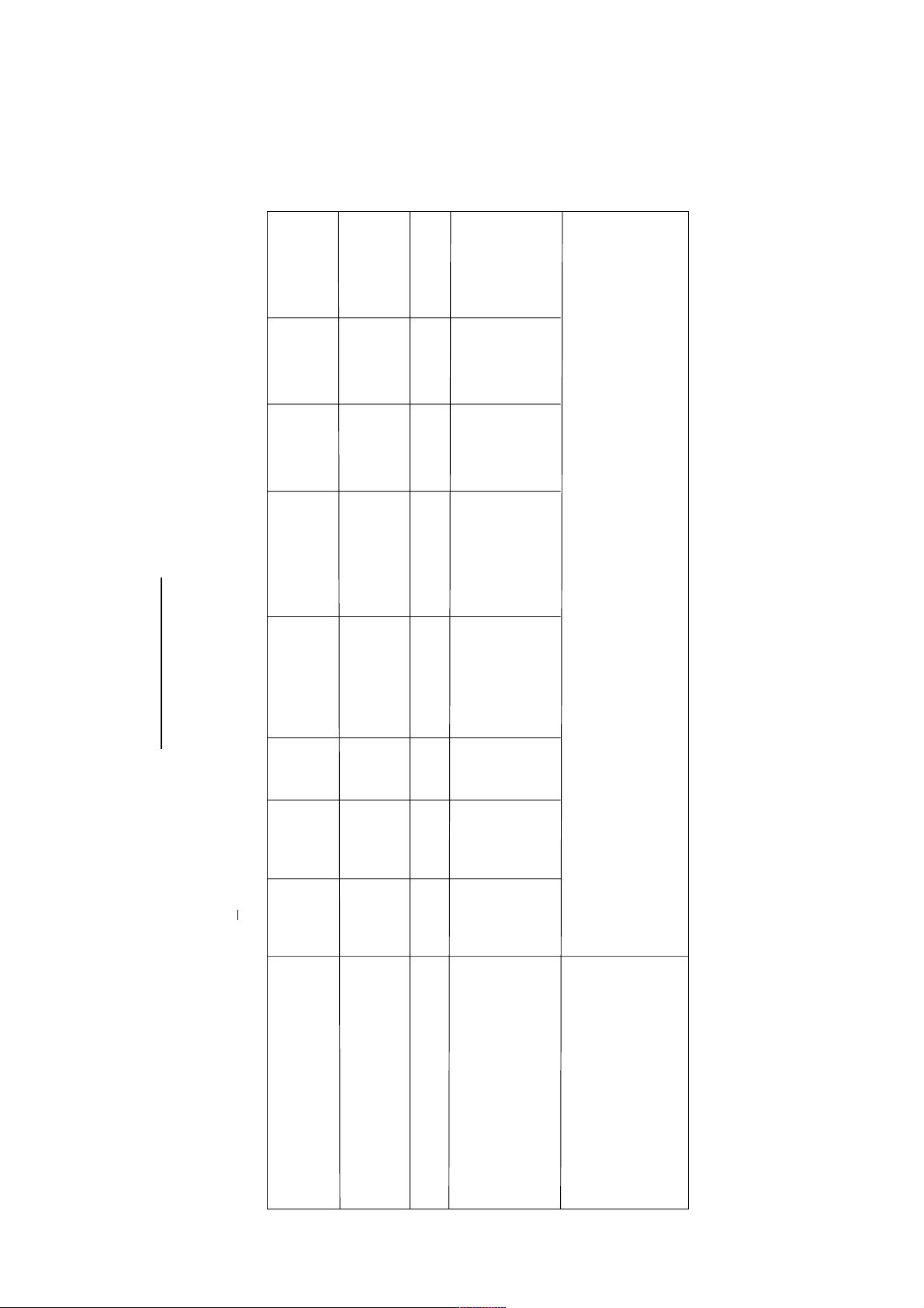
ITEMS OF MEASUREMENT
VIDEO SENS. AT S/N 30db
SOUND SENS. AT S/N 30db
AGC CHARACTER
SELECTIVITY -1.5 MHz
+ 8 MHz
COLOR SENS.
COLOR LOCK - IN RANGE
VERTICAL LOCK - IN RANGE
HORIZONTAL LOCK - IN RANGE
MAX BRIGHTNESS
MAX OUTPUT POWER
L - VHF
H - VHF
UHF
L - VHF
H - VHF
UHF
STANDARD
< 57
< 57
< 60
< 42
< 42
< 48
> 60
> 35
> 40
< 45
> +300
> 6
> 400
> 140
> 1
UNIT
dbuv
dbuv
dbuv
dbuv
dbuv
dbuv
db
db
db
dbuv
Hz
Hz
Hz
cd / m2
W
OUTPUT POWER AT 10% THD
BUZZ
AFC RANGE
MIN. VOL HUM
RESOLUTION HORIZONTAL
VERTICAL
LINEARITY DISTORTION VERTICAL
HORIZONTAL
RASTER DISTORTION
REMOTE CONTROL DISTANCE
ANGLE
POWER CONSUMPTION ( AT NORMAL CONDITION )
POWER CONSUMPTION ( AT MAX. CONDITION )
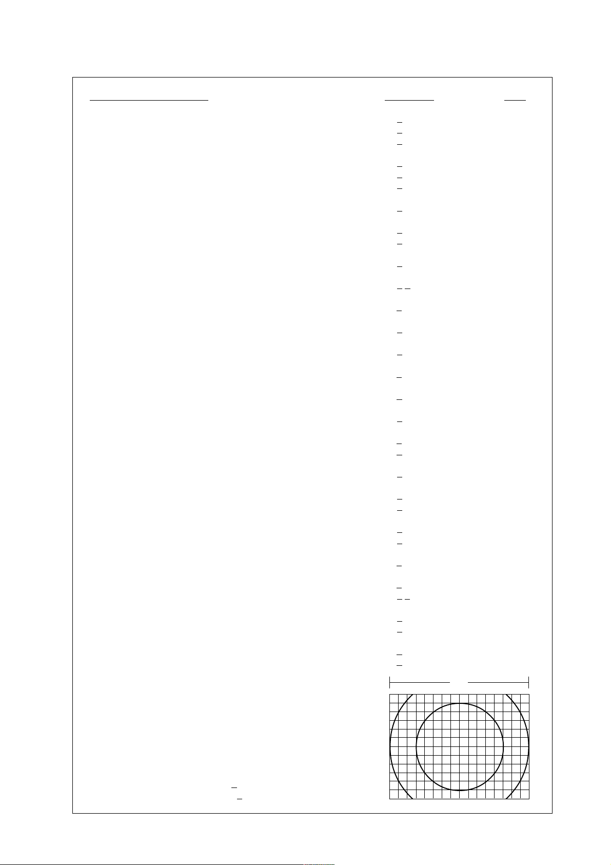
CONVERGENCE DISLOCATION AT AREA "A"
AREA "B"
( see fig.1 )
> 0.7
< -40
> +1
> -0.5
< 20
> 300
> 400
< 10
< 10
< 5
> 5
> +15
< 60
< 70
< 0.4
< 0.8
W
db
MHz
MHz
mV
LINES
LINES
%
%
%
METER
DEGREE
WATTS
WATTS
%
%
H
VIDEO INPUT LEVEL : 1.0V P-P + 3dB
AUDIO INPUT LEVEL : 0.5V RMS + 3dB
Fig.1
A
B
SM - 49PM P.2
MODEL : 14"
CHCHCH
MHz
MHz
MHz
MHz
SPECIFICATION
E2 - S2
( CA TV )
PAL - BG
PAL - BG
BG / DK
PAL - SECAM -
BG / DK
PAL - SECAM -
P AL - I
E2 - S10
( HYPER )
1 - 5
( HYPER )
1 - 5
(UK)
E5 - S20
E21 - E69
E5 - S41
E21 - E69
6 - 12
21 - 69
6 - 12
21 - 69
21 -69
38.9
38.9
38.9
38.0
39.5
33.4
34.47
33.4
34.47
32.4 33.4
34.47 34.47
31.5 32.5
33.57 33.57
33.5
35.07
5.5
5.5
6.5 5.5
15625 LINE
6.5 5.5
6
50 Hz
14"
75 OHM
PAL - BG
PAL - I / I
SUPPL Y VOLTAGE : AC220V 50Hz > + 10% / -20%
SYSTEM :
38.9
2 - 4
5 -12
21 - 69
4 - 13
21 - 69
CHANNEL L - VHF :
H - VHF :
UHF :
33.4
38.9
32.9
VIF FREQUENCY :
SIF FREQUENCY :
5.5
34.47
6.0
34.47
CHROMA IF FREQUENCY :
INTER-CARRIER FREQUENCY :
SCANNING HORIZONTAL :
VERTICAL :
ANTENNA INPUT IMPEDANCE :
CRT :
SM -49PM P.3

ALIGNMENT INSTRUCTION
I.PLEASE READ BEFORE ATTEMPTING SERVICE
1.Do not connect any antenna plug directly to the tuner socket and do not
connect any equipments directly to the TV chassis,otherwise it may be
burnt out the TV or equipment,execept an isolation transformer is used for
main power source or the TV sets.
2.Never disconnect any leads while receiver is in operation.
3.Disconnect all power before attempting any repairs.
4.Do not short any portion of the circuit while power is on.
5.For safety reasons,all parts replaced should be identical(for parts and
part numbers see parts list).
6.Before alignment the set must be pre-heated for 30 minutes or more and
erase magnetism thoroughly from CRT front chassis frame by erase coil.
II.TEST EQUIPMENT
1.Colour Bar/Dot/Cross Hatch
2.Oscilloscope
3.Vacuum Tube Voltmeter
4.Volt Ohumeter
5.High Voltage Meter
6.Ampere Meter (0.5 Class,DC 3mA Max.)
7.Demagnetizing Coil
8.Closed Caption Encoder
9.High Pot Tester.
I. B+ ADJUSTMENT
1.Connect a digital voltmeter to B+ and Ground.
2.Set Brightness Contrest to minimum.
3.Adjust Screen Volume on FBT until the picture can just been seen.
4.Adjust VR901 to obtain a reading of 112
+ 0.5V(FOR samsung CRT).
II. AFC ALIGNMENT
1.Disconnect the soldering pad ‘F’.
2.Input the signal from Pattern Generator ( IF 38.9MHz ) colour bar to R101 and GND.
3.Adjust the T101 until the colour bar show on the screer.
4.Select ‘SELF VCO’in D-MODE.
5.Press the AFC button on the handset.
6.About few seconds screen willbe show AFT OK.
*REMARK: No this factory on Normal R.C.
III.AGC ALIGNMENT
1.Receive CH69 (UHF) and input filed strength. TUNER INput Signal 62 + 3dB,
2.Connect a digital Voltmeter between the TUNER AGC Terminal and Ground.
3.Select RAGC item,Adjust the value to 3F,and then adjust the AGC value obtain the voltage drop down 0.4V.
Remark: 1 The drop down voltage should be more than and tends to 0.4V.
2 No observable noise can be seen.
IV.VERTICAL LINEARTY ADJUSTMENT
1.PAL (50Hz)Adjustment
(1).Receive Crosshatch Pattern (50Hz) .
(2).Select VLIS item adjust value to normal regular picture.
2.NTSC (60Hz) Adjustment.
(1).Reneive Cross hatch Patter (60Hz).
(2).Select VILN item adjust value to normal regular picture.
3.Repeat 1.2. receive Cross hatch 50Hz and 60Hz is same picture.
V. VERTICAL HEIGHT ADJUSTMENT
1.PAL (50Hz) Adjust .
(1).Recive Mono scope Patter (50Hz).
(2).Select HITS item adjust value to normal regular picture.
2.NTSC (60Hz).
(1).Receive Mono scope Patter (60Hz).
(2).Select HIT item adjust value to normal regular picture
3.Repeat 1.2. receive Mono Scope Patter 50Hz and 60Hz is same picture.
SM-49PM P.4
 Loading...