

Roadstar TRA-1955 Service Manual

Service Manual
- TRA-1955
R
TRA-1955
Service Manual
- TRA-1955
2. PR OD UC T SAFETY N OTIC E
Som e elec trical and m echanical parts hav e special saf ety related
charac teristics which are of ten not evident f rom visual inspection, nor can
t he protection they give necessarily be obtained by replacing them with
components rated for higher voltage, wattage, etc. Parts that have special
saf ety characteristics are identif ied by a on schem atic and parts list.
U se of a substitute replacement that does not have the sam e saf ety
charac teristics as the recomm ended replacement part might create shock,
f ire, and/or other hazards. Product Saf ety is under rev iew continuously
and new ins tructions are issued whenev er appropriate.
3. SERVIC IN G PR EC AU TION S
C AU TI ON Before servicing the unit covered by this serv ice m anual and
it s supplem ents, read and follow the SAF ETY PR ECAUTIONS on this page
NOTE. I f unforeseen circum stances create a conf lict between the following
s ervicing precautions and any of the saf ety precautions, alway s f ollow
t he saf ety precautions. Remember, Safety F irst.
General Serv icing Precautions.
a Alway s unplug the unit’s AC power cord f rom the AC power source
bef ore.
(1) Remov ing or reinstalling any com ponent, circuit board, m odule, or any
other unit assembly .
(2) Disc onnecting or reconnecting any unit electrical plug or other electrical
connec tion.
(3) Connec ting a test substitute in parallel with an electrolytic capacitor in
the unit.
Caut ion
a. Wrong part substitution or incorrect polarity installation of electrolytic
c apacitors may result in an explostion hazard
b. D o not def eat any plug/socket B + voltage interlocks with which the
unit covered by this serv ice m anual might be equipped
c . Do not apply AC power to this unit and/or any of its electrical assem blies
unles s all solid-state dev ice heat sinks are correctly installed
d. Alway s c onnect a test unit instrument’s ground lead to the unit’s chassis/
s ground bef ore connecting the test instrum ent’s positive lead. Always
rem ov e the test instrument’s ground lead last.
IMPO RTANT SERVICE SAFETY INFORMATION
1. SAF ETY PR EC AU TION S
Bef ore returning a unit to the customer, always m ake a saf ety check of
t he entire unit, including, but not limited to the f ollowing items.
a. Be sure that no built-in protectiv e devices are defectiv e and/or hav e
been defeated during servicing.
(1) Prot ective shields are provided to protect both the technician and
t he custom er. C orrectly replace all m issing protective shields
inc luding and removed for serv icing convenience.
(2) W hen reinstalling the chassis and/or other assem blies in the
c abinet, be sure to put back in place all protectiv e dev ices,
inc luding, but not lim ited to, nonmetallic control knobs insulating
f ishpapers , adjustm ent and com partm ent cov ers/shields and
isolation resistor/capacitor networks. D o not operate this unit or
permit it to be operated without all protectiv e dev ices correctly
ins talled and f unctioning.
b. Be sure that there are no cabinet openings through which an adult or
c hild m ight be able to insert their fingers and contact a hazardous
v olt age. Such openings include, but are not lim ited to, excessiv ely
wide cabinet ventilation slots, and an im properly fitted and/or incorrectly
s ecured cabinet back cov er.
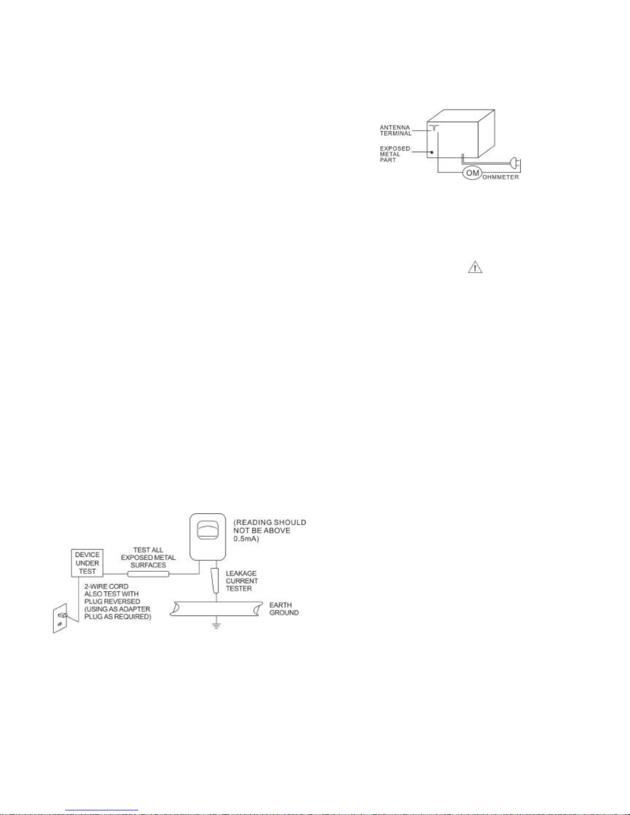
c . Leakage C urrent Hot Check - W ith the unit com pletely reassem bled,
p lu g t he AC l i ne c o rd d i re c tl y i nt o a 230 V A C o ut l et . ( D o n o t u se a n
isolation t ransform er during this test.) Use a leakage current tester or
a m etering s ystem that com plies with American N ational Standards
I nstitute (AN SI) C 101.1 “Leak age C urrent f or Appliances” a nd
U nderwriters Laboratories (UL) 1410, (50.7). W ith the unit AC switch
f irst in the ON position and then in the OFF position, m easure f rom a
k nown earth ground (m etal water pipe, conduit, etc.) to all exposed
m et al pars of the unit (antennas, handle bracket, m etal cabinet,
s crewheads, m etallic ov erlay s, control shaft, etc.), especially and
ex posed metal parts that of fer an electrical return path to the chassis.
Any c urrent m easured m ust not exceed 0.5 m illiamp Rev erse the unit
power c ord plug in the outlet and repeat test. AN Y MEASU REMENTS
N OT W I TH IN TH E LIMITS SPE C IF IED H ER EN IN IN D IC ATE A
POTEN TI AL SH OC K HAZ AR D TAHT MU ST BE ELIMINATED BEF OR E
R ETUR NI NG THE U NIT TO TH E CU STOMER .
AC Leakage Tes t
+ -
d. I nsulation Resistance Test C old Check
U nplug the power supply cord and connect a jum per wire between the
two prongs of the plug.
Turn on the power switch of the unit.
Measure the resistance with an ohm meter between the jum pered AC
plug and each exposed m etallic cabinet part on the unit, such as
s crewheads, antenna, control shafts, handle brackets, etc. W hen the
exposed m etallic part has a return path to the chassis, the reading
should be bet ween 1 and 5.2 megohms. When there is no return path to
t he chassis, the reading must be “inf inite”. If it is not within the limits
spec if ied, there is the possibility of a shock hazard, and the unit must
be repaired and rechecked before it is returned to the custom er.

STEP SET SIGNAL SET DIAL ADJUST ADDJUST FOR
1 465 KHz GAND T3(1 st IF) MAXIMUM
2 CLOSED T5(2 nd IF) OUTPUT.
3
4 520KHz GANG CLOSED L5(AM OSC COIL)
5 1630KHz GANG OPEN CT4(AM OSC TRIM) MAXIMUM
6 600KHz BAR1(AM ANT COIL) OUTPUT.
7 1400KHz CT3(AM ANT TRIM)
8
STEP SET SIGNAL SET DIAL ADJUST ADDJUST FOR
MAX AMPLITUDE
BALANCED
10.7 MHz CURVE WITH
2 OPEN T4(2 nd FM IF) 10.7mhzAT ZERO
CROSSOVER.
3
STEP SET SIGNAL SET DIAL ADJUST ADDJUST FOR
4 87.5 MHz GANG CLOSED L4(FM OSC COIL)
5 108.5 MHz GANG OPEN CT2(FM OSC COIL) MAXIMUM
6 90MHz 90MHz L2(FM RF COIL) OUTPUT
7 106 MHz 106 MHz CT1(FM RF TRIM)
8
ALIGNMENT PROCEDURES
1.Set the BAND switch to AM
2.Connect an RF generator to a standard radiating loop
3.Connect a VTVM across the speaker voice coil.
REPEAT STEPS 1 AND 2 TO OBTAIN MAXIMUM OUTPUT.
REPEAT STEPS 6 AND 7 TO OBTAIN BEST TRACKING
FM ALIGNMENT
1.Set the BAND switch to FM
2.Connect an RF generator to the emitter of Q2 through a 0.1uF capacior and ground.
3.Connect an oscilloscope to pin 8 of IC I through a 0.02uF capacitor and ground.
1.Connect an RF generator to the FM antenna terminal and ground.
2.Connect a VTVM across the speaker voice coil.
REPEAT STEPS 6 AND 7 TO OBTAIN MAXIMUM OUTPUT.
1 GAND T1(1 st FM IF)
REPEAT STEPS 1 AND 2 TO OBTAIN MAXIMUM OUTPUT.

 Loading...