

Page 1

R
- SM-142
- SM-142
SM-142
Service Manual
Service Manual
Page 2

Page 3

CONTENTS PAGE
Safety Instructions 1
Technical Specifications 2
Instructions Manual 4
Pin Voltages of IC’s 15
Pin Voltages of Some Transistors 18
Oscillograms 19
Electrical and Service Adjustments 21
Trouble Shooting Guide 24
Convergence Adjustments 31
Channel Frequency Tables 33
Part List 37
Circuit Diagrams Attac hed
Page 4

PIN VOLTAGES OF IC'S
IC101 (TDA956X H)
TV signal processor-Teletext Decoder with embedded u-Controller
Pin Connection V DC (*) Pin Connection V DC (*)
1
Volume +/- 3,2 (3,2)
2
Status 1 0 (0)
3
Status 2 0 (0)
4
Digital ground for u-controller 0 (0)
5
Not connected 0.75 (0.25)
6
Standby on/off 0.01 (3.9)
7
Analog Gnd of text decoder and dig Gnd of TV
processor
8
Secam PLL decoupling 2.3 (0)
9
2nd supply voltage TV proc (8V) 8.0 (0.26)
10
Supply volt.deccoup. of dig. Gnd of TV
processor
11
Phase 2 filter 2.73 (0)
12
Phase 1 filter 3.9 (0)
13
Gnd 3 for TV processor 0 (0)
14
Decoupling bandgap 4.0 (0)
15
AVL (90 versions) / East/West drive signal (110
versions)
16
V-drive B output 1.0 (0)
17
V-drive A output 1.0 (0)
18
IF-1 input 1.87 (0)
19
IF-2 input 1.87 (0)
20
Reference current input 3.9 (0)
21
Vertical sawtooth capacitor 3.8 (0)
22
Tuner AGC output 4.3 (0)
23
Sound IF input 1 1.9 (0)
24
Gnd 0 (0)
25
Gnd 0 (0)
26
Norrow band PLL filter 2.2 (0)
27
AVL (Automatic Vol. Levelling) 0.42 (0.08)
28
Ext. Audio (audio 2) input 3.73 (0.08)
29
Audio 3 input (not connected) 3.73 (0.09)
30
H-drive output 2.33 (0.26)
31
Sandcastle output-Hor.Fly.input 0.56 (0.25)
32
Decoupling sound demodulator 2.0 (0)
33
QSS intercarrier output / AM output 3.43 (0.3)
34
EHT / overvoltage protection input 2.2 (0.08)
35
IF-PLL loop filter 2.45 (0)
36
Sound IF AGC 0.5 (0)
37
QSS output 0.6 (0)
38
IF video / selected CVBS output 3.0 (0)
39
main supply voltage TV processor 8.0 (0.25)
40
Internal CVBS input 3.8 (0)
3.0 (0.5)
0 (0)
5.0 (0)
41
Gnd for TV processor 0 (0)
42
External CVBS input 0 (0)
43
Gnd for TV processor 0 (0)
44
SVHS-Y input 3.35 (0)
45
SVHS-C input 0 (0)
46
White stretch capacitor 3.4 (0)
47
CVBS output 2.8 (0.07)
48
Audio output/AM audio output 3.45 (0)
49
2nd IF video output (not conn.)
50
2nd RGB / YUV insertion input 0.17 (0)
51
Red input 2.6 (0)
52
Green input 2.6 (0)
53
Blue input 2.6 (0)
54
Beam current limiter input 2.6 -3.4 (0)
55
Black current input / V-guard input 4.6-5.7 (0)
56
Red output see oscilog.
57
Green output see oscilog.
58
Blue output see oscilog.
59
Analog supply of text decoder and
dig.supply of TV proc (3.3V)
60
OTP programming voltage 0 (0)
61
Dig. Supply to core (3.3V) 3.3 (3.3)
62
X-tal Gnd 0 (0)
63
X-tal input
64
X-tal output
65
Programming Reset (not connected) 0 (0)
66
Dig. Supply to periphery (3.3V) 3.3 (3.3)
67
SCL1 (Eeprom) 3.3 (3.3)
68
SDA1 (Eeprom) 3.3 (3.3)
69
IR input 3.3 (3.3)
70
Not connected
71
SCL see oscilog.
72
SDA see oscilog.
73
MSP reset (IC301) 4.9 (0)
74
Mute 0 (3.3)
75
SVHS switching 3.3 (3.3)
76
L/L' switching 3.3 (3.3)
77
F Blank MM Not conn. 3.3 (3.3)
78
Program + 3.3 (3.3)
79
CVBS sync filter 3.3 (1.8)
80
Program - 3.3 (3.3)
3.3 (3.3)
(*)
Standby values are given in parenthesis
Note: The function of pin 15, 27, 33 and 48 is dependent on the mode of operation (mono intercarrier mode / QSS IF amplifier
and East-West output or not) and is controlled by some software control bits.
Page 5
IC 301- MULTI STANDARD SOUND PROCESSOR (MSP 3400D)
Pin Connection V DC Pin Connection V DC
1
Not connected
2
Gnd 0
3
Gnd 0
4
Gnd 0
5
Gnd 0
6
Gnd 0
7
Supply 4.9
8
Supply 4.9
9
SCL 2.4-2.6
10
SDA 1.8-2.1
11
Not connected 2.4
12
Not connected 2.4
13
Not connected 2.4
14
Not connected 4.9
15
Not connected 0.7
16
Not connected 0.7
17
Not connected 0.7
18
Supply 4.9
19
Gnd 0
20
Not connected 0.7
21
Gnd 0
22
Gnd 0
23
Gnd 0
24
MSP, RESET 4.9
25
Headphone sound output (R) 2.1
26
Headphone sound output (L) 2.1
27
Gnd 0
28
R-out 0.1-2.1
29
L-out 0.1-2.1
30
Dolby on (C) 0.1-2.1
31
Dolby on (SUB) 0.1-2.1
32
Dolby on (S) 0
33
Scart 2 sound output (R) 3.7
34
Scart 2 sound output (L) 3.7
35
Gnd 0
36
Scart 1 sound output (R) 3.7
37
Scart 1 sound output (L) 3.7
38
Volume capacitor Main
39
Analog Supply 8
40
Volume capacitor Aux
41
Gnd 0
42
Analog ref. supply 3.7
43
Scart 4 input (L) 3.7
44
Scart 4 input (R) 3.7
45
Gnd 0
46
CINCH - sound input (L) 3.7
47
CINCH - sound input (R) 3.7
48
Gnd 0
49
Scart 2 sound input (L) 3.7
50
Scart 2 sound input (R) 3.7
51
Gnd 0
52
Scart 1 input (R) 3.7
53
Scart 1 input (L) 3.7
54
A/D converter ref. Voltage 2.5
55
Mono sound input 3.7
56
Gnd 0
57
Analog Supply 4.9
58
IF input 1 1.5
59
- 1.5
60
IF input 2 0
61
Gnd 0
62
Crystal oss. input 2.3
63
Crystal oss. output 2.3
64
Gnd 0
IC303, IC304 Audio Output IC
Pin Connection V DC Pin Connection V DC
1
Left In 1.6
2
Left In V 1.6
3
Mute 15.3
4
Right In V 1.6
5
Right In 1.6
6
Gnd 0
7
8
Right out 14.2
9
VS 28
10
Left out 13.9
11
12
Left In 0.6
0,5-0,9
0,5-0,9
IC501 TDA835X
Pin Connection V DC Pin Connection V DC
1
Input A 0,98 (0)
2
Input B 0.94 (0)
3
Supply voltage 14,7 (1.0)
4
Output B 7,55 (0,4)
5
Gnd 0 (0)
6
Vertical Flyback Supply Voltage 45,6 (10,9)
7
Output A 7,64 (0,1)
8
Guard Output 0,3 (0)
9
Feedback Input 7,9 (0)
IC601 MC44608 AP
Pin Connection V DC Pin Connection V DC
1
Demag 0.85 (0.0)
2
I sense 0.1 (0.32)
3
Control input 5 (5.5)
4
Gnd 0
(*)
Standby values are given in parenthesis
5
Driver 2.1 (0.14)
6
VCC 12.3 (8.8)
7
Not connected -
8
VI 116 (117)
Page 6

IC701 TDA6107
Pin Connection V DC Pin Connection V DC
1
Red in 2.3-2.5
2
Green in 2.5-2.7
3
Blue in 2.5-2.7
4
Gnd 0
5
Black 4.5-5.5
6
Vdd supply 190
7
Red out 134-137
8
Green out 128-130
9
Blue out 130-137
Page 7
Pin
Standby VDC
TV ON VDC
Standby VDC
TV ON VDC
PIN VOLTAGES OF SOME TRANSISTORS
1. PH601 (PC127FY) PHOTOCOUPLER 2. T603 (BC848) NPN
Standby VDC
1 B C E B C E
2
3
4
3. T604 (BC848) NPN 4. T605 (BC848) NPN
12.5
11.5
5.5
8.8
Standby VDC TV ON VDC Standby VDC TV ON VDC
B C E B C E B C E B C E
ON VDC
11
10
5
12.3
T603
0.6 0.02 0 0.1 0.3 0
T604
5. T606 (BC848) NPN 6. T607 (BC848) NPN
T606
7. T307 (BC848) NPN
T307
0.02 12.7 0 0.7 0.05 0
Standby VDC TV ON VDC Standby VDC TV ON VDC
B C E B C E B C E B C E
0.6 0 0 1 6.8 0
B C E B C E
0.6 0 0 0.1 15 0
T605
T607
0.6 0.02 0 0.1 0.7 0
0.6 0 0 0.1 2.5 0
Page 8
Note:
TV is connected to a patern generator (Colour bar, sound 1 kHz).
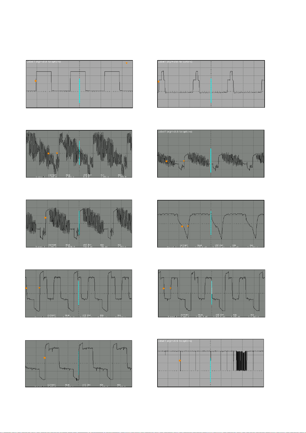
OSCILLOSGRAPHS OF SOME IC PINS
500 mV/div, 20 usn/div, Vpp=1.2 V, 15625 kHz
500 mV/div, 20 usn/div, Vpp=2.1 V, 15625 kHz
500 mV/div, 20 usn/div, Vpp=2.7 V, 15625 kHz
500 mV/div, 20 usn/div, Vpp=2.6 V, 15625 kHz
500 mV/div, 20 usn/div, Vpp=2.4 V, 15625 kHz
1. IC101 (TDA956X)
Pin 30
2V/div, 20 usn/div, Vpp=4.9 V, 15625 kHz
Pin 38
2V/div, 20 usn/div, Vpp=2.9 V, 15625 kHz
Pin 47
Pin 31
2V/div, 20 usn/div, Vpp=5.6 V, 15625 kHz
Pin 40
Pin 55
Pin 56 Pin 57
Pin 58 Pin 71
2 V/div, 1 msn/div, Vpp=5.2 V
Page 9
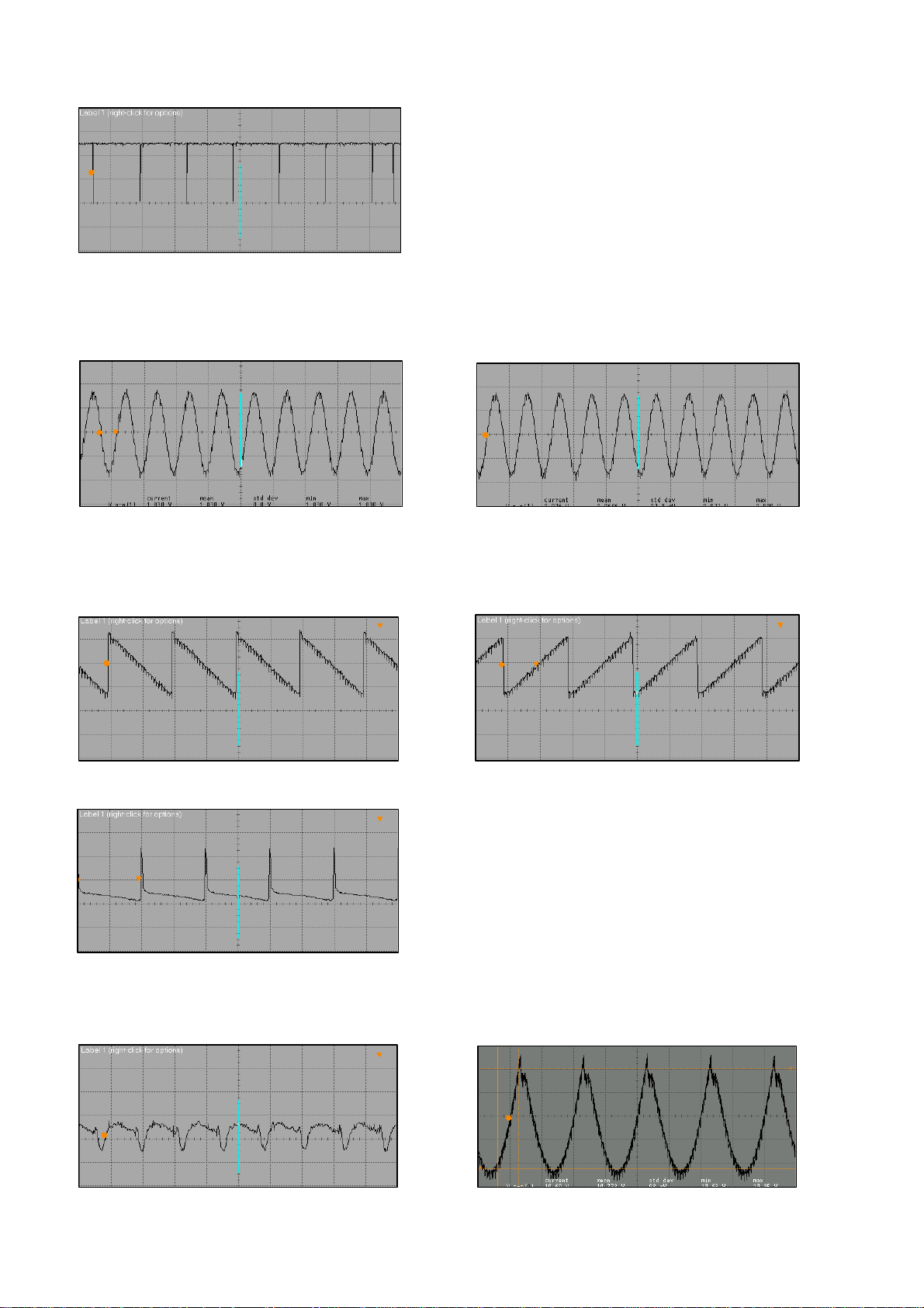
Pin 72
2 V/div, 1 msn/div, Vpp=5.2 V
2. IC301 (MSP34XX)
Pin 28
500 mV/div, 1 msn/div, Vpp=1.8 V
3. IC501 (TDA835X)
Pin 1
500 mV/div, 10 msn/div, Vpp=1.4 V, 50Hz
Pin 7
500 mV/div, 10 msn/div, Vpp=44.6 V, 50Hz
Pin 29
500 mV/div, 1 msn/div, Vpp=1.8 V
Pin 2
500 mV/div, 10 msn/div, Vpp=1.4 V, 50Hz
4. T501 (2SK2381)
Gate (EW drive)
Drain (EW drive)
2 V/div, 10 usn/div, Vpp=10.7 V, 50 Hz
Page 10

1. ELECTRICAL ADJUSTMENTS
1.1. Supply Voltage Adjustment
Connect a digital voltmeter to the cathode of diode D611 at the AV1 mode of the TV and set the
screen voltage to the minimum with the screen potentiometer. Adjust the main supply voltage (B+)
with P601 potentiometer to the following value (after adjustment, readjust Screen voltage).
25” : 145 VDC
28” : 145 VDC (147 VDC for A66EAK071X11)
28” Pure Flat 16/9 : 140 VDC
28” Super Flat 16/9 : 140 VDC
29” Pure Flat : 125 VDC
29” Super Flat : 125 VDC
32” Pure Flat 16/9 : 140 VDC
32” Super Flat 16/9 : 131 VDC
33” : 158 VDC
2. SERVICE ADJUSTMENTS
You need the special service remote control to enter and exit the service menu of the TV (you can
order it from the manufacturer). All buttons of the Service RC are same with the user remote control,
only service menu In / Ot was added to it (please see the picture below).
Navigation
Service In/Out : Enters to / exits from the Service Menu
P+ / P- : Moves upward / downward inside the menu
V+ / V- : Changes the value or option
Green & Red : For screen adjustment (pls see the explanation below)
OK : Changes the brightness, contrast values to 00, 3F and preset values sequentially (Its
OSD is shown). When P+ / P- buttons pressed the service menu is re shown.
2.1. AGC Adjustment
Apply a signal with amplitude 65±1 dBuV to the antenna input of TV with a pattern generator (switch
sound carrier to Off and switch “Video Ext” to On). Switch on the Service Menu with the Service RC
and find the AGC with P+ / P- buttons. Measure the 38.9 MHz signal on pin 11 (IF) of Tuner with an
oscilloscope. Adjust AGC to get following values:
BG versions : 840 ± 20 mVpp
BG/DK NICAM : 540 ± 20 mVpp
Page 11

2.2. Geometry Adjustments
• Apply a FUBK or Philips Test pattern.
• Enter Service Menu with Service RC and select “VSLP” option with P+ / P- buttons (In this option,
the upper half part of the pattern is shown and lower half part is blanked).
• Adjust VSLP such that middle line of the pattern is cut.
• For 16/9 sets, adjust VZOM to 25. On 4/3 sets, when VZOM is selected, set switches to 16/9
mode. In this case, adjust the circle of the pattern just touches to the upper and lower edges.
Re adjust the VSLP if required.
• Adjust vertical position with VSHT, vertical linearity with SCOR and vertical height with VAMP.
• For 4/3 sets, adjust the horizontal amplitude with EWW.
For 16/9 sets, adjust the 16/9 horizontal amplitude with EWW1 and 4/3 horizontal amplitude with
EWW (EWW value is 21 lower than EWW1 value).
• For 16/9 sets, find the VZM1 option and adjust such that second lines from top and bottom just
touches to the edges.
• Adjust horizontal centering with HSHT, parabola with EWPW and trapezium with EWT.
• For 4/3 sets, adjust the 16/9 general parabola with EWP1.
• Adjust the upper corner parabola with EWCU and lower corner parabola with EWCL, vertical
parallelogram with HPAR, horizontal bow with HBOW.
• Exit from the Service Menu.
2.3. Screen Adjustment
• Enter the Service Menu with the Service RC and select “SCRN” option with P+ / P- buttons and
switch to ON with V+ / V- button. “BRI 32” is shown on the screen. With the red and green
buttons of Service RC, select “BRI 00”.
• Adjust the screen potentiometer to the level where the screen is just black. Change to “BRI32”.
• By pressing one of V+ / V- buttons, get the picture (SCRN is switched to Off).
• Exit from Service menu.
2.4. White Balance Adjustment
• Enter the Service Menu with the Service RC and select “GRN” option with P+ / P- buttons and
adjust it to “32” V+ / V- button.
• Adjust RED and BLUE for white balance. If white balance can not be adjusted properly
change GRN value.
• Adjust BLOR and BLOG for red and green cut off.
• Exit from Service menu.
2.5. Feature Options
Tuner : Panasonic, Phillips, Sharp, Temic
STD : STBY-Off (Default)
Head : Yes (Headphone available), No
SCRN : Off, On (used in screen adjustment)
AV : 01 (1 Scart), 03 (2 Scarts), 04 (2 Scarts + Front AV), 05 (2 Scarts + Front AV+ SVHS)
SSTD : BG only, I only, BG+DK, BG + LL’, All SYS
STYP : NICAM On (available), NICAM Off
Toptext : Yes (available), No
TXT table : West (West Europe), East (East Europe), Cyrillic
Hotel : On (Hotel Mode), Off (TV Mode)
Subwoofer : Yes (available), No
CRT : 4/3, 16/9
Peak1 : Yes (16/9 sets), No (4/3 sets)
Car : Yes (Default)
Page 12

2.6. Default Preset Values
Note:
1. PF means Pure Flat and SF means Super Flat.
2. The values in the table are decimal and shown in paranthesis on the OSD of TV.
32"
28"
28"
AGC Automatic gain control 14 14 14 14 14 14 14 14
EEPE Reset the eeprom, all values lost 00 00 00 00 00 00 00 00
PEAK Peaking 32 32 32 32 32 32 32 32
GRN Green level 37 37 37 37 37 37 37 37
RED Red level 40 35 35 32 35 40 40 42
BLUE Blue level 34 32 33 26 33 34 34 34
BLOG Black level offset green 30 28 30 25 30 31 31 27
BLOR Black level offset red 36 41 40 33 40 41 41 37
YDLY Luminance delay 04 04 04 04 04 04 04 04
SAT Saturation 20 20 20 20 20 20 20 20
HUE Sharpness 32 32 32 32 32 32 32 32
CON Contrast 40 40 40 40 40 40 40 40
CDR Cathode Drive Level 05 05 05 05 05 05 05 05
BRI Brightness 32 32 32 32 32 32 32 32
EWT East West Trapezium 28 17 24 28 27 24 24 26
EWCU EW upper corner 32 22 14 32 39 07 07 27
EWCL EW lower corner 32 48 38 38 42 22 22 37
EWPW EW parabola width 17 08 08 14 12 12 12 20
HSHT Horizontal shift 35 35 40 31 29 29 29 35
EWW East West Width 60 37 36 55 57 39 39 62
VAMP Vertical amplitude 46 42 42 43 45 45 45 48
SCOR S correction 25 25 17 31 25 17 17 25
VSHT Vertical shift 29 27 28 28 26 31 31 25
VSLP Vertical slope 32 32 32 34 29 35 35 32
RGB OSD brightness level 01 01 01 01 01 01 01 01
VZOM Vertical zoom 39 39 39 39 39 39 39 39
PWLT Peak white limiting 11 07 07 11 11 07 07 11
IFOF Offset IF demodulator 32 32 32 32 32 32 32 32
HPAR Horizontal parallelogram 32 32 32 32 32 32 32 32
HBOW Horizontal bow 32 32 32 32 32 32 32 32
TEST Added for EMC purposes 09 09 09 09 09 09 09 09
EWP1 16/9 EW parabola width (for only 4/3 sets) 08 05 05 09 09 05 05 13
EWW1 East West Width (for only 16/9 sets) - 58 57 - - 60 60 VZM1 Vertical Zoom (for only 16/9 sets) - 58 59 - - 59 59 -
2.7. Exit from Service Menu
During exit from service menu, the software version and feature options (hexadecimal number) are
shown on the screen. For example: VER14_2 BASIC, C697H
25"
28"
16/9
P F
16/9
S F
29"
P F
29"
S F
32"
16/9
P F
16/9
S F
33"
Page 13

Note:
1. All values in the diagrams are for 230 VAC mains supply.
2. Before replacing T601, check following components: R640, R604, R605, R609, C615.
3. Burst type standby mode was designed (Fixed frequency is
for normal operation) . In standby the output voltages drop to about 1/10 of the normal
operation values (except +12V which stays same), i.e. from +145V to 14.7V, from 15V to 1.1V,
from 28V to 2.5V. In standby, Standby signal from IC101 is high. Then, T605 conducts, T604
blocks and thristor TH601 conducts. Therefore, +145 line which is now14.7V is connected to
12V. The regulation is done by ZD603 in standby and by ZD602 (TL431) in normal mode.
No operation
Stand-by LED is off
No SMPS Voltages
Check 300V DC on C613
YES
Check transistor T601 is OK.
Drain 300 VDC, 2.3-2.8 VAC
Gate 1.2 VDC
YES
Check 120 VDC at pin 8 of
IC601, MC44608
Check 8.8 VDC at pin 6 of
YES
IC601
YES
Check 1.2 VDC at pin 5 of
IC601
YES
Check and replace T601,
2SK2545
NO
NO
YES
NO
NO
NO
POWER SUPPLY DEFECTS (I)
Check Fuse ST601
Check and replace
Fuse ST601
D601 and 602 are open
circuit
C610 is open or capacitor
value is low. D6107 is short
or IC601 is defective.
If R639 is OK, replace IC601
YES
NO
21.5 kHz for standby and 38.8 kHz
Check power switch, L601,
Diode SD602, D605, D604,
Capacitor C603, P603
If C613 has a voltage lover
than 300 VDC replace it
Page 14

POWER SUPPLY DEFECTS (II)
Stand-by Voltages OK
Check 4.2 VDC at pin 6 of IC101
Switch on the TV set. Check voltage 0.05 V pin
6 of IC101 and 0.28 V at R439
No operation
YES
YES
Check and replace IC101
POWER SUPPLY DEFECTS (III)
Stand-by Voltages are
abnormal
Check the standby voltage (it should be
-
NO
Standby voltage is around 160 V instead of
14.7V
NO
NO
YES
YES
Check connection to R409 and R641
Check the voltage 3.3 V
at pins 59, 66 of IC101 and pin 8 of IC402
Check and replace R617, R641, R626, T603,
ZD603, T604, T605, T607, C621, C623
Check the voltage 4 VDC at the cathode of
D615. Check and replace T605 and PH601
Page 15

POWER SUPPLY DEFECTS (IV)
When TV is on, voltages
145V,15V,11.8V, 3.3V, 8V,
5V, 28V are not at their
proper values
+B voltage is around 160V instead of 145V.
+B voltage is 20-80V instead of 145V.
Voltages 15V, 8V, 5V are missing. Other
Voltages 8V, 5V are missing. Other voltages
NO
NO
NO
YES
YES
YES
YES
Check and replace T607, R625, R645, PH601,
ZD602.
There should be 14 VAC at R612 and 11.8
VDC at cathode of D614.
Check the voltage 16 VAC at fuse S602. If it is
missing check and replace S602 and D613
Check and replace IC603, R631, R627, T606,
C638, IC602, C637.
Page 16

PICTURE AND COLOUR DEFECTS
Check video out signal at pin 38 of IC101
Only white raster visible on screen
No picture
Raster OK
YES
NO
YES
Check the tuner pin voltages. Check the
voltage 3.6-4.6 V at pin 18, 19 of IC101.
Check and replace F101, IC101.
Check CVBS signal with an oscilloscope. The
video signal goes through R103, T104, R154,
F104, T105, C150 to pin 40 of IC101
NO
There are flyback lines on the screen
NO
There are black drops on the screen.
NO
No picture. There is a Red, Green or Blue raster
YES
YES
NO
Check Hor. Flyback signal at pin 31 of IC101.
Check and replace C129 which is connected
to pin 11 of IC101.
Check and replace C13 9
Check and replace R167, R206, R118, R136,
R137, R135, IC101.
Page 17

HORIZONTAL DEFLECTION CIRCUIT DEFECTS
Power supply voltages are
OK. There is no high voltge
Check 15V at the collector of T503.
YES
Check the voltages 1.42 VDC and 0.92 VAC at
+
YES
Check the voltages 0.28 VDC, 0.92 VAC and
YES
Remove T504. Check the voltage 145 VDC at
YES
Check 2 VAC at the base of T504.
NO
NO
NO
NO
NO
Check and replace R503 and TR501 Hor.
Driver transformer
Check voltage 8V at pin 9, 39 of IC101. If
present replace IC101.
Check and replace D505 and C503.
Check and replace R525 and Line Output
Transformer.
Check and replace T503, TR501 and R513.
YES
Check and replace D507, D508, C518, C519,
C521. Place T504 to its position. Check the
operation of Line Output Transformer.
YES
There is a noise heard from Line Output
Transformer. Check and replace T501, R516
and C520.
NO
Replace Line Output Transformer.
Page 18

VERTİCAL DEFLECTION CIRCUIT DEFECTS
There is a horizontal line on
the screen
Check 16 VDC at pin 3 of IC501.
YES
Check 35 VDC at pin 6 of IC501.
YES
Check 2.2 VDC at pin 1 of IC501.
YES
Check 2.2 VDC at pin 2 of IC501.
YES
Check 7.4 VDC at pin 7 of IC501.
Check 7.2 VDC at pin 4 of IC501.
NO
NO
NO
NO
NO
Check and replace R127 (at pin 20 of IC101),
C126 (at pin 21 of IC101), R526, D513, C527,
R521.
Flyback lines are visible. Check and replace
R527, D512, C526, R522, C517.
If R122 is open IC501 becomes defective and
16 VDC components fail. Check them before
replacing IC501.
Lower half of the screen is black. Check and
replace R123 and IC101.
A Horizontal line is visible. Check and replace
R518, R519 and IC501.
YES
Replace IC501
Page 19

AUDIO DEFECTS (I)
p
No sound.
Picture is OK.
Check 28 VDC at pin 9 of IC304.
Audio signal at pins 1,5 of IC304 are OK.
NO
Audio signal at pins 28,29 of IC301 are OK.
NO
Audio signal at R150 Trap Filter is OK.
NO
NO
Check and replace components R156, L105,
AUDIO DEFECTS (II)
Volume decreases t o minimum.
Volume increases to maximum.
NO
NO
YES
YES
YES
YES
YES
Check and replace components R341, D612,
S603.
Check signals at pins 8, 10 of IC304.
Check and replace IC304.
Check and replace R307, T301, R310, C326,
C332, R308, T305, R319.
Check and replace C230 and IC301.
Check and replace R437 and R444.
Check and replace R436 and R445.
Check 3.3 VDC at
in 78 of IC101.
NO
Volume Up/Down buttons change proramme
NO
Pop sound is heard when switch off.
NO
Check and replace R321, R318, T307.
YES
YES
Check and replace R438 and R441.
Check 3.3 VDC at pin 1 of IC101.
Check and replace R429, R317, C335.
Standby voltages of T307: B(0.6V), C(0V)
Operation voltages of T307: B(0.1V), C(15.5V)
Page 20

PART LIST
291103
CC-CHIP 100PF J 50V /0805 N
C101
C111
293108
CC-CHIP 10NF K 50V /0805 X7
C103
C149
290473
CC-CHIP 47PF J 50V /0805 NP
C104
C107
252112
EC 100UF 16V 11*6 R:5
C105
250111
EC 1UF 16V 11*5 R:5
C110
292479
CC-CHIP 4.7NF K 50V /1206 X
C112
293230
CC-CHIP 22NF K 50V /0805 X7
C118
C120
259223
EC 2.2UF 63V 11*5 R:5
C124
C139
C507
294231
CC-CHIP 220NF K 16V /0805 X
C125
274107
C-PEM 100NF J 100V R:5
C126
290561
CC-CHIP 56PF J 50V NPO 0805
C131
C165
290222
CC-CHIP 22PF J 50V /0805 NP
C136
294476
CC-CHIP 470NF K 16V /0805 X
C145
251107
EC 10UF M 16V 11*5 R:5
C146
C148
C162
C167
C638
294475
CC-CHIP 470NF M 25V /1206 Z
C151
291822
CC-CHIP 820PF J 50V /0805 N
C158
C160
290684
CC-CHIP 68PF J 50V /0805 NP
C186
291225
CC-CHIP 220PF K 50V /0805 X
C202
C203
291473
CC-CHIP 470PF K 50V /0805 X
C209
C366
291474
CC-CHIP 470PF J 50V /1206 N
C214
C210
251478
EC 47UF 16V 11*5 R:5
C217
C221
C224
C302
C314
250470
EC 4.7UF 16V 11*5 R:5
C220
C222
C226
C225
294111
CC-CHIP 100NF K 25V /0805 X
C229
C235
294331
CC-CHIP 330NF K 16V /0805 X
C239
C241
299152
CC-CHIP 1.5PF C 25V/0805
C308
C313
292110
CC-CHIP 1NF K 50V /0805 X7R
C322
C324
250227
EC 2.2UF 16V 11*5 R:5
EXTERNAL SPEAKER
C330A
292105
CC-CHIP 1NF K 50V /1206 X7R
C332
C334
253101
EC 1000UF 35V 25*13 R:5
C338
C340
252229
EC 220UF 16V 11*8 R:5
EXTERNAL SPEAKER
C344
C346
252112
EC 100UF 16V 11*6 R:5
C352
C353
C337
C401
C402
253106
EC 1000UF 25V 20*13 R:5
C354
C355
C620
291477
CC-CHIP 470PF J 50V /0805 N
C405
C406
290334
CC-CHIP 33PF J 50V /0805 NP
C413
272101
C-PEM 1NF K 50V R:5
C503
251478
EC 47UF 16V 11*5 R:5
C504
C639
274230
C-PEM 220NF J 100V R:5
C505
C524
C523
200680
CC 68PF J 500V NPO R:5
C506
292223
CC-CHIP 2.2NF K 50V /0805 X
C508
C509
252476
EC 470UF 25V 11*10 R:5
C512
C527
272154
C-PPM 1.5NF J 1600V R:15
25",28"4/3
C513
272103
C-PPM 1NF J 2KV R:15
28"16/9
C513
271331
C-PPM 330PF J 1500V/1600V R
32"
C513
294109
CC-CHIP 100NF K 50V /0805 X
C515
C516
273104
C-PPM 10NF J 1.5/1.6KV R:22
25",28"4/3
C518
273119
C-PPM 11NF J 1.5/1.6KV R:22
33"
C518
273120
C-PPM 12NF J 1.5/1.6KV R:22
28"16/9
C518
273131
C-PPM 13.1NF J 1.5/1.6KV R:
29",32"
C518
273151
C-PPM 15NF J 1KV R:15
16/9 sets
C519
273228
C-PPM 22NF J 1KV R:15
4/3 sets
C519
274563
C-PPM 560NF J 250V R:15
C520
C521
274563
C-PPM 560NF J 250V R:15
25",32",28"4/3
C521
274684
C-PPM 680NF J 250V R:15
33"
C521
274684
C-PPM 680NF J 250V R:15
28"16/9
C521
250100
EC 1UF 160V 11*6.3 R:5
C522
251225
EC 22UF 16V 11*5 R:5
C528
272110
C-PEM 1NF J 100V R:5
C529
274224
C-PEM 220NF K 275V-AC R22.
C601
C602
274105
C-PEM 100NF J 250V R:10
C603
C701
202105
CC 1NF K 1KV Y5P R:5
C604
C605
C607
C608
274102
C-PEM 100NF J 63V R:5
C606
PART NO DESCRIPTION NOTES
POSITION NUMBERS
Page 21

PART LIST
252150
EC 150UF 400V 40*22 R:10
C613
201471
CC 470PF 2KV
C614
C619
203330
C-PPM 33NF J 630V R:15
C615
202220
CC 2.2NF M 250VAC Y5U R:10
C616
253101
EC 1000UF 35V 25*13 R:5
C621
293681
CC-CHIP 68NF K 25V /0805 X7
C624
293474
CC-CHIP 47NF K 50V /0805 X7
C625
C626
252104
EC 100UF 200V 25*16 R:7.5
C629
C627
251228
EC 22UF 200V 11.5*8 R:5
C629
201108
CC 100PF 500V NPO R:5
C631
294108
CC-CHIP 100NF K 50V /1206 X
C632
C326
293332
CC-CHIP 33NF K 50V /0805 X7
C634
293475
CC-CHIP 47NF K 50V /1206 X7
C636
251120
EC 10UF 10V 5*4 R:5
C637
C901
251109
EC 10UF 250V 16*10 R:5
C702
C703
273225
C-PEM 22NF J 63V R:5
C704
202221
C-CE 2.2NF K 2KV Y5P R:7.5
C705
202106
CC 1NF K 50V Y5P R:5
SVHS
C920
C921
C922
C923
273471
C-PEM 47NF K 63V R:5
C940
C941
201472
CC 470PF K 50V SL R:5
EXTERNAL SPEAKER
C962
C963
291101
CC-CHIP 100PF J 50V /1206 N
C981
C982
303195
DIODE 4148 MELF
LL'
D102
303223
DIODE-CHIP BA682 SOD80
LL'
D103
D104
302296
DIODE 1N4148 26MM
D401
D402
302289
DIODE 1N4148 52MM
D401
D402
D505
303195
DIODE 4148 MELF
D503
D504
303109
DIODE ERC06-1500
D507
303244
DIODE RGP30K
D508
302948
DIODE 1N4007
D509
D701
300305
DIODE BA157
D510
D511
D512
303227
DIODE RGP15J
D513
303209
DIODE BAV21
D515
D702
D703
D704
303217
DIODE RGP10J
D601
D615
303308
DIODE RF2007
D602
D603
D604
D605
303215
DIODE RGP10G
D607
D614
303214
DIODE UF4006
D608
D609
303206
DIODE RGP30MS
D611
303228
DIODE RGP30D
D612
D613
303988
LED LTL 4224 RED (SHORT LEG
28"
D901
303942
LED LTL4224 RED
25"
D901
303900
LED ROT
29",32",33"
D901
303993
LED LTL4221N D:3 R/D RED
D980
303991
LED IR SIR563SB3F 23/940
D981
56749
SAW FILTER OFW G1985M
BG
F101
56760
SAW FILTER OFW J1956M
P I
F101
56709
SAW FILTER OFW K3953M
PS DK
F101
56708
SAW FILTER OFW K3958M
LL'
F101
56767
SAW FILTER OFW K9456M
LL'
F102
56721
SER.FILTER TPS5.5MWA
PS BG DK
F104
56745
SER.FILTER TPS6.0MB
P I
F104
53740
COIL 1UH K LAL03
F105
056640-01
SER.FILTER MKT40.4MA110P-TF
DK
F105
56744
SAW FILTER OFW G9353M
DK
F106
056640-01
SER.FILTER MKT40.4MA110P-TF
LL'
F108
458642
IC-CHIP TDA9563H/N1/3
BG I
IC101
458643
IC-CHIP TDA9565H/N1/3
BG DK LL'
IC101
452510
IC 4053B CMOS 16SOIC
IC102
452575-01
IC MSP3400G
NON VIRTUAL DOLBY
IC301
452800
IC MSP3410G PSDIP64 AUDIO P
NON VIRTUAL DOLBY
IC301
452595
IC MSP3411G
VIRTUAL DOLBY
IC301
452374
IC L78L05 ACZ TR
IC302
PART NO DESCRIPTION NOTES
POSITION NUMBERS
Page 22

PART LIST
452368
IC TDA7262 PWR AMP SGS THOM
33"
IC304
452482
IC TDA7263
IC304
452784
IC-CHIP M24C08-WMN6 (EEPROM
IC401
452976
IC TDA8359 J
IC501
452487-01
IC MC44608P40
IC601
451517
IC TDB7805CT T0220CASE
IC602
451518
IC KA317TU T0220CASE
IC603
IC604
50S310
INSULATER BUZ90 17*12*.15
IC603
452520
IC TDA6108JF
IC701
452521
IR RECEIVER TSOP 1838
IC901
452382
IC-CHIP S3C1840DA9/SMB1
IC980
53711
COIL 10UH K (TAIYO) LAL03
L101
L301
L302
L401
L402
53719
COIL CHIP 1UH
L102
L105
L106
53794
COIL CHIP 330NH /0805
L102
53737
COIL-CHIP 8.2UH K /1206
L104
53735
COIL-CHIP 18UH K /12
L201
L303
51707
COIL 6MH E/W 11.1
L501
51605
COIL H.LINEARITE 39UH
25",29"
L502
53330
COIL H.LINEARITE 45UH
28" 16/9
L502
52692
COIL LINEARITY 30UH (TERMAL
28" 4/3, 32", 33"
L502
51729
BRIDGE COIL 1.5MH
25",28"4/3,33"
L503
051798-01
BRIDGE COIL 1.8MH
28"16/9,32"
L503
51813
BRIDGE COIL 850UH
29"
L503
51737
LINE FILTRE 2*18MH E-TYPE
L601
53734
COIL 4.7UH LAL03
L603
53739
COIL CHOKE 50UH
L604
53352
COIL- CHOKE 10UH R0814 14.1
L701
55139
CHOKE COIL 50MHZ 600R PH-WB
L962
L963
133118
R-VAR 10K V(2.5MM) 5*3
P601
452408
IC PC123FY2PHOTO COUPLER
PH601
56952
CRYSTAL 18.432MHZ +-30PPM
Q301
56946
CRYSTAL 12MHZ
Q401
56210
CER.RESONATOR GSB455E
Q980
173154
RC-CHIP 15K J 1/10W /0805
R112
174104
RC-CHIP 100K J 1/10W /0805
R114
101683
CFR 680R J 1/4W /6 52MM
R124
172274
RC-CHIP 2.7K J 1/8W/1206 (T
R126
173392
RC-CHIP 39K %1 1/10W/0805
R127
171393
RC-CHIP 390R J 1/10W /0805
R129
173479
RC-CHIP 47K J 1/10W /0805
R139
R142
171182
RC-CHIP 180R J 1/10W /0805
R147
R163
171150
RC-CHIP 150R J 1/10W /0805
R154
171102
RC-CHIP 100R J 1/10W /0805
R158
R105
171221
RC-CHIP 220R J 1/10W /0805
R164
R429
173273
CFR-CHIP 27K J 1/10W /0805
R165
171332
RC-CHIP 330R J 1/10W /0805
R170
R425
179001
RC-CHIP 0R /0805 2*1.25
R176
R151
172333
RC-CHIP 3.3K J 1/8W /1206
R201
C336
170750
RC-CHIP 75R J 1/10W /0805
R209
R213
171334
RC-CHIP 330R J 1/8W /1206
R214
R215
172101
RC-CHIP 1K J 1/10W /0805
R216
R217
171104
CFR-CHIP 100R J 1/8W /1206
R220
R221
172335
RC-CIHP 3.3K J 1/10W /0805
R314
R310
173104
RC-CHIP 10K J 1/8W /1206
R317
R633
172123
RC-CHIP 1.2K J 1/8W /1206
R326
R330
171821
RC-CHIP 820R J 1/8W /1206
R328
R332
170473
CFR-CHIP 47R J 1/8W /1206
R329
R162
129150
RWF 1.5R J 1.5W
NOT FOR 33"
R341
119104
RWF 1R J 1.5W (UFLB) 73MM
33"
R341
179002
RC-CHIP 0R /1206
R342
R228
170332
RC-CHIP 33R J 1/10W /0805
R401
R412
PART NO DESCRIPTION NOTES
POSITION NUMBERS
Page 23

PART LIST
170390
RC-CHIP 39R J 1/8W /1206
R404
170101
RC-CHIP 10R J 1/10W /0805
R421
172474
RC-CHIP 4.7K J 1/8W /1206
R434
172475
RC-CHIP 4.7K J 1/10W /0805
R435
R440
170472
RC-CHIP 47R J 1/10W /0805
R437
R438
171471
RC-CHIP 470R J 1/10W /0805
R439
R218
120234
RMF 22R J 1/2W
R503
110270
RMF 27R J .75W 52MM
R503
174180
RC-CHIP 180K J 1/10W /0805
R504
173333
RC-CHIP 33K J 1/10W /0805
R505
R102
173276
RC-CHIP 27K J 1/8W /1206
R506
114110
RM 100K %1 1/4W 26MM
R508
121182
RW 180R J 2W 73MM
R510
109472
CFR 0.47R J 1/2W /9 52MM
25", 28" 4/3, 33"
R513
114151
RM 150K J 1/2W
R514
R517
119476
RMF 4.7R J 1W
25",28" 16/9, 29",32",33"
R516
R527
119271
RM 2.7R J 1/2W
25"
R518
R519
119271
RM 2.7R J 1/2W
R518
R519
119181
RMF 1.8R J 1W 52MM
28" 4/3
R518
119220
RM 2.2R J 1/2W
28"16/9
R519
129395
RMF 3.9R J 0.5W 52MM
32"
R519
129395
RMF 3.9R J 0.5W 52MM
R519
119476
RMF 4.7R J 1W
28"4/3
R519
R527
111224
RMO 220R J 1W
R520
119480
RM 0.47R J 1/2W
25"
R521
R607
129471
RF 4.7R J 0.25W 52MM
R522
122114
RWF 1K J 1.5W 73MM
R523
113113
RMF 10K J 1/2W
R524
119152
RMO 1.5R J 2W
R525
119184
RMO 1.8R K 3W R:20
R525
129475
RW 4.7R J 7W (YATIK)
29"
R525
129109
RWF 0.1R J 0.75W 73MM
R526
103116
CFR 10K J 1/4W /6 52MM
R528
119684
RMF 0.68R J 1W
25"
R529
119122
RMF 1.2R J 1W
28" 16/9
R529
119155
RMF 1.5R J 1W
32".33"
R529
119110
RMF 1R J 1W
28" 4/3
R529
129109
RWF 0.1R J 0.75W 73MM
29"
R529
113335
RMO 33K J 1W
R531
154216
NTC 5.1R M (S234R)
R601
154225
PTC 18R/3 PIN
28"16/9, 29",33"
R602
112393
RM 3.9K %1 1/4W 52MM
R605
119336
RM 0.33R %1 1W
R607
111101
RMO 1K J 1W
R608
113681
RMO 68K J 2W
R609
115470
RM 4.7M J 1/2W 52MM
R610
102105
CFR 1K J 1/2W /6 52MM
R611
119109
RNF 0.1R J 0.4W (UFLB) 52MM
R612
100473
CFR 47R J 1/4W /6 52MM
R617
R333
110476
RMO 47R J 3W
R618
113475
RMO 47K J 1W
R621
R629
173101
RC-CHIP 10K J 1/10W /0805
R622
R626
172273
RC-CHIP 2.7K J 1/10W /0805
R623
114115
RM 115K %1 1/4W
28" 16:9, 29", 32"
R625
114152
RM 150K F 1/4W 52MM
25, 28" 4/3, 33"
R625
112131
RM 1.3K %1 1/4W 26MM
R627
111391
RM 390R %1 1/4W 26MM
R628
172105
RC-CHIP 1K J 1/8W /1206
R630
R236
111241
RM 240R %1 1/4W 26MM
R631
R632
100154
CFR 15R J 1/2W 52MM
R639
103273
CFR 27K J 1/4W /6 52MM
R645
PART NO DESCRIPTION NOTES
POSITION NUMBERS
Page 24

PART LIST
103475
CFR 47K J 1/4W /6 52MM
R705
102159
CFR 1.5K J 1/2W /9 52MM
PS 29" HHOP U44
R711
R713
R715
R716
102166
CFR 1.5K J 1/4W /6 26MM
EXTERNAL SPEAKER
R903
54261
FUSE 2.5AT (215 SER.)
S601
54280
FUSE 3.15AT (215)
S601
54263
FUSE T2A
S602
54264
FUSE T4A
S603
10760
SLIDE SWITCH 4P2P/4PST
32" 29"
S960
31251
SCART SOCKET 14.1
SK202
SK201
10861
ON/OFF SWITCH BK98
25"
SW901
010840-01
TACT SW LONG STEN 2LEG
33"
SW901
SW902
401141
TRN-CHIP BC848B SOT23
T103
T104
T105
T106
401142
TRN-CHIP BC858B SOT23
T301
T302
T303
T305
T308
400989
TRN BC558B
T306
T309
401141
TRN-CHIP BC848B SOT23
T307
T403
401279
TRN 2SK2381
T501
401218
TRN BC618
T503
401215
TRN BU508DF
T504
401142
TRN-CHIP BC858B SOT23
T980
401141
TRN-CHIP BC848B SOT23
T603
T604
410026
THRYSTOR MCR22-8
TH601
51709
DRIVER TRANSFORMER 11.1
TR501
57834
DST-SANAL 28" 16:9 14.1
28" 16:9
TR502
58934
FBT SANAL 29" 14.1 (C-TYPE)
29"
TR502
57534
FBT-SANAL 2528 14.1
25", 28"
TR502
57334
FBT-SANAL 33' 14.1
33"
TR502
059834-TR1
SMPS 28" 16:9/SLOT TR/.....
TR601
59934
SMPS SANAL 29" 14.1
29"
TR601
59534
SMPS-SANAL 2528 14.1
25", 28"
TR601
59834
SMPS-SANAL 28" 16:9 14.1
28" 16:9
TR601
59334
SMPS-SANAL 33" 14.1
33"
TR601
51805
COIL PFC 56MH DTH30563H ELI
TR602
7RZ136-PH3
TUNER PH ASIMETRIK UV1316/A
TU101
31866
CONN.HOUSING X2006 GREY
X102
31035
PIN HEADETR 2.5MM 7.PC.MOLE
LL'
X104
31854
CONN.HOUSING X2003 GREY
X301
X405
X940
31858
CONN.HOUSING X2004 GREY
X302
X402
31780
CONN.HOUSING 2'LI GREY
X303
X501
31872
CONN.HOUSING X2007 BLACK
X403
31856
CONN.HOUSING X2003 BLACK
X404
31794
CONN.MALE HOR. 4.PIN PLUG
X502
31821
CON.HOUSING X2.5TMK 2204 GR
X503
31675
CON.HOUSING 2P MALE
X601
X602
X604
X605
031530-01
INCHANG/CRT SOCKET ISHM05S-
X703
31165
KONN. CINCH ........... YEL
SVHS
X921
31162
KONN. CINCH RCA PJ803-4 YEL
SVHS
X921
31164
KONN. CINCH ........... RED
SVHS
X922
31161
KONN. CINCH RCA PJ803-3 RED
SVHS
X922
31163
KONN. CINCH ........ WHITE
SVHS
X923
31160
KONN. CINCH RCA PJ803-2 WHI
28" SVHS
X923
31784
KONN.S-VHS B10B MONAKOR
SVHS
X924
31423
HEADPHONE JACK YKB21-5103
X941
31357
CON.HOUSING X2.5TMK 2904 G
EXTERNAL SPEKAER
X962
31021
PIN HEADETR 2.54MM 3.PC.MOL
29" 32"
X964
31020
PIN HEADETR 2.54MM 4.PC.MOL
29" 32"
X965
303826
DIODE Z. BZX55C 15V
ZD501
303771
DIODE Z. UZT33V
ZD502
451885-01
IC TL431CLP (ON SEMICONDUCT
ZD602
303799
D- ZENER MTZJ12B
ZD603
300193
DIODE Z. BZX55C9V1-GPS(VISH
ZD606
PART NO DESCRIPTION NOTES
POSITION NUMBERS
Page 25

PART LIST
Z33110
B8 CHASIS-25" P/NC/PTX/2SC/
P BG 25"
Z54110
B8 CHASIS-25" PS/DK/NC/PX/2
PS DK 25"
Q29110
B8 CHASIS-28" PS/DK/NX/2S/H
PS DK 28" SVHS
T78110
B8 CHASIS-SD 28" 16:9 P/NX/
P BG 28" 16:9
U99110
B8 CHASIS-SD 29 SF PS/LL/NV
PS LL 29" EXT.SPE. VDB
U44110
B8 CHASIS-SD 29" SF PS/SNCX
PS 29" EXT.SPEAKER
V26110
B8 CHASIS-SD 32"16:9 PI/VD/
P I 32" EXT.SPE. VDB
W67110
B8 CHASIS-SD 33" P/PTX/ST/2
P BG 33"
7RZ273
BACK COVER R/C A.TYPE GREY
54C500
CORD POWER
EUROPE
55127
CORE FERRIT
7RZ206
COVER BATTERY BOX R/C GREY
056428-PS1
CPT PS W66EHK51X36
28"16/9
056432-PS2
CPT PS W76EKW10X21 P.FLAT
32"
056325-VC4
CPT VC A59EHJ13X38
25"
056328-VC6
CPT VC A66EHJ13X62
28"4/3
056329-VC2
CPT VC A68EGD049X30 (S.FLAT
29"
056333-VC3
CPT VC A80AEJ15X04
33"
31541
CRT SOCKET 29" DOUBLE FOCUS
32"
7PZ172
CU ASSY 29"T12 14.1
533167-AS
DEGAUSING COIL 33"
33"
525167-AS
DEGAUSSING COIL ASSY 25" BA
25"
628167-AS
DEGAUSSING COIL ASSY 28" BA
28"4/3
55597
FERRITE BEAD 12*8
500258
HOLDER CABLE OVER HEAT SINK
U98160
IR/LED ASSY 29"T12 14.2
EXT.SPEAKER
U99160
IR/LED ASSY 29"T17 14.2
PS LL 29" EXT.SPE. VDB
7PZ212
KNOB PROGRAM CONTROL PANEL
56D204
LENS LED 21SI-BKT12
28"
5JT100-AS
MAIN SW ASSY 20/21MNTR-TD1-
28"
7MZ100-AS
MAIN SW ASSY 21TD1 14.1 LOC
29"
7MY100-AS
MAIN SW ASSY 21TD1/TW1 FIL.
28" 16/9
5U5100-AS
MAIN SW ASSY 28TL2 W/FUSE W
32"
7TT100-AS
MAIN SW ASSY 28TL2/TL3 FILT
29"
10971
MAIN SWITCH GDE S40 4/100A-
33"
010712-03
POWER SWITCH S40 4/100A-250
28",29",32"
571925
PUSH CATCH NWE TYPE
PS DK 28" SVHS Q29
7P3187
RC ARC.TYPE ARC.PRINTED SIL
P I 32" HHOP VDB V26
6VM187
RC ARC.TYPE SILVER 14.1
P 33" W67
7UK187
RC A-TYPE GREY 14.1
P 25" Z33
7TK187
RC BEKO TYPE FUME 14.1
P 28" 16:9 T78
7PE187
RC BEKO TYPE M.GREY 14.1
PS LL 29" HHOP VDB U99
5T1187
RC BEKO TYPE SILV.14.1
PS DK 25" Z54
7UB109-AS
SPE.SUB 4R/20W(NOM)21T04/25
29"
7UB107-AS
SPEAKER 8R/15W(MAX)21T04/25
29"
6X1107-AS
SPK.8R/15W(MAX) 32"T20/T21
EXTERNAL SPEAKER
010840-01
TACT SW LONG STEN 2LEG
28"
10845
TACT SW WITH GREEN LED
32" 29"
10844
TACT SWITCH 2 LEG (MTSB)
25"
600302
TERMINAL BATT.BOX(-) R/C
600301
TERMINAL BATT.BOX(+) R/C
600303
TERMINAL BATT.BOX(+-) R/C
401047
TRN BC337-25
7UB108-AS
TWEETER 10R/10W(N)21T04/25T
29"
7VA108-AS
TWEETER DYNAMIC D=52 8R/15W
33"
7RZ207
WINDOW FILTER R/C ARC.TYPE
Please note that Product Part List Files should be investigated for the mechanical parts like cabinets, etc.
PART NO DESCRIPTION NOTES
POSITION NUMBERS
Page 26

Page 27

14.2 CTV CHASSIS
S99.820
H_DRIVE
+33V
TUNER14_1
TU101
AGC
AS
TUNE
2
1
3
R172
0R
C104
47p
C102
C106
R102
1n
table
33k
R101
+5V
L101
3.9k
10u
SCL
SDA
R179
+5V
(47R LL'& mono LL')
L_L’
40.4MHz
F108
68p
C181
D103
C180
R183
1n
BA682
10k
D104
R194
BC848
BA682
T109
100R
R181
100R
R180
2.2k
BC848
SECAM L/L’ MODULE
ONLY MONO
R104
R107
470R
6.8k
BC848
T101
SC.OUT_MONO
R103
3.3k
EHT_COMP
VDRIVEA
VDRIVEB
EW_DRIVE
CVBS_IN_SCART1
OPTION -WEB
F_BLANK_MM
SVHS_SOURCE
+8V
+3.3V
R666
1k
R441
2.2k
T402
BC848
D403
1N4148
R407
10k
R416
10k
L_L'
(220R LL'& mono LL')
BC848
T401
R433
10k
R443
MUTE
10k
CAB3
+8V
IC302
78L05
STANDBYQ
SC3_IN_L
DVSUP
SC3_IN_R
AVSUP
D_CTR_OUT0
D_CTR_OUT1
SCL
SDA
SC1_OUT_R
RESETQ
CAPL_A
SC1_OUT_L
AHVSUP
CAPL_M
SC1_IN_R
DACA_R
SC1_IN_L
DACA_L
IC301
table
ANA_IN2+
DACM_L
ANA_IN1+
DACM_R
ANA_IN-
MONO_IN
AGNDC
DAC_C
VREFTOP
SC2_OUT_R
DAC_S
SC2_OUT_L
SC2_IN_R
DAC_SUB
SC2_IN_L
XTAL_IN
SC4_IN_R
XTAL_OUT
SC4_IN_L
AUD_CL_OUT
I2S_DA_IN2
NC1
NC4
NC2
NC5
ADR_SEL
NC6
NC3
VREF2
VREF1
I2S_CL
AHVSS
I2S_WS
ASG4
I2S_DA_OUT
ASG2
I2S_DA_IN1
ASG1
ADR_DA
AVSS
ADR_WS
TESTEN
ADR_CL
NC7
DVSS
X602
2
C603
100n/250V
1
DEGAUSS
X605
X601
2
2
ST601
2.5A
1
1
AC
C601
INPUT
table
MAINS
X660
1
2
3
4
5
C606
100n/63V
C703
C701
10u/250V
100n/250V
R709
220R
R708
R705
47k
2.2M
C702
10u/250V
C704
22n/63V
C520
C521
560n 250V 560n 250V
560n 250V
820n 250V
1.5u 250V
560n 250V
820n 250V
560n 250V
560n 250V
1u 250V
560n 250V
680n 250V
R125
12K
29"&90°
X662 X663 R235
CON10
CON9
CON10
CON9
-
-
7
OUT
IN
18
57
4
9
10
24
38
39
40
25
26
29
28
30
32
31
62
63
20
21
22
23
27
35
41
45
48
51
56
61
64
C613
150uF 400V
220uF 400V
220uF 400V
220uF 400V
220uF 400V
220uF 400V
R168 R197 R167 R199
-
0R
-
L301
10u
C315
C311
C307
C302
47n
47u/16V
1n
220p
C314
C309
C303
47u/16V
10n
2.2n
R342
R306
0R
100R
R304
100R
R305
220R
C304
100n
C310
10u/63V
C312
10u/63V
R302
1k
C317
C305
1n1n
+8V"
R303
R310
3.3k
1k
C318
C306
1n
1n
R307
1k
C320
BC858
C319
T301
1n
1n
R308
1k
CAB.14
C316
C321
1n
1n
R343
10k
C322
1n
R345
10k
R301
0R
Q301
18.432MHz
C308
C313
1.5p
1.5p
SUBWOOFER
DOLBY
SUBWOOFER
DOLBY
CABLE.9b
FROM SMT
C650
100k 2W
4.7n/1kV
8
C652
100n
R602
table
R601
5.1R
C604
1n/1kV
C602
L601
2x18mH
table
PFC coil
of 56mH
or 70mH
C605
on 110 chassis
1n/1kV
D601
RGP10J
R639
15R
R605
3.9k %1
5
4
MC44608
3
6
IC601
2
7
1
8
29" & 32"
Others
X703
table
GND
GND
G1
BLUE
CRT SOKET
GREEN
HEATER
G2
HEATER
RED
R716
G2
1.5k
D701
1N4007
R239
0R
C705
4.7n/1.5kV
R328 R332
820R
1/8W
820R
1/8W
820R
1/8W
820R 820R
1/8W 1/8W
820R
1/8W
910R
1/8W
0R
0R
-
AQUA
SMPS
R341
1/8W
820R
1.5R
1.5W
1.5R
1.5W
1/8W
820R
820R
1/8W
1.5R
1.5W
1.5R
1.5W
820R
1/8W
1.5R
1.5W
910R
1/8W
1R
1.5W
47K
-
-
-
-
T310
BC848
R309
1k
C323
1n
R650
RF2007
R611
1k
15u/25V
OPTION - PROLOGIC
R344
C184
table
R311
1k
IC650
TNY254P
D602
RF2007
D603
R606
table
C610
HS301
7RZ.304
7RZ.304
7PZ.304
7VA.304
7PZ.304
7UA.304
R312
0R
R313
10k
D650
RGP10J
C607
1n/1kV
2SK2545
GND
Heater
N.C.
220V
-
R339
C326
100n
CAB13
+8V"
R314
3.3k
BC858
T302
C324
1n
BC858
T304
C325
1n
C330
100n
R326
1.2k 1/8W
1.5k 1/8W
6
5
47123
D604
RF2007
D605
RF2007
C608
1n/1kV
T601
R607
table
D607
RGP10G
C642
4.7u/25V
X703
031.541
031.530
X702
CRT
1
2
3
4
R717
R504
180K 1/10W
390K 1/10W
390K 1/10W
390K 1/10W
390K 1/10W
390K 1/10W
CAB8
C337
100u/16V
R316
3.3k
BC858
T303
0R
+8V"
C327
1n
C330A
table
C330
table
+8V"
R315
3.3k
C329
100n
C330A
-
2.2u 16V
-
R327
18R 1/8W
47R 1/8W
C651
2.2n/1kV
TR650
SMT(+5V)
47R 1/4W
PH650
PC123FY
CABLE.9a
R609
68k
C613
table
JP622
D608
UF4006
R608
1k
L603
4.7uH
table
HS101
***
BG
I
DK
L/L’
DOLBY PROLOGIC BG/DK
DOLBY PROLOGIC I
DOLBY PROLOGIC L/L'
+8V
R320
330R
BC558
T306
R323
3.3k
BC858
T308
R322
R317
10k
BC848
T307
R322
R318
table
4.7k
C335
table
(47u MM)
R319
C333
3.3k
100n
C332
BC858
1n
T305
JP305
CABLE.6
C334
1n
1
1
R324
2
2
0R
C336
X304
X305
table
C366
CABLE.7
470p
C3361nC340
3.3k 1/8W
1000u 35V
1000u 35V
R330
R331
1.2k 1/8W
18R 1/8W
1.5k 1/8W
47R 1/8W
D651
R619
FB650
0,1R
RGP15D
C653
C657
1000u/16V
220n
R652 R653
R651
470R
R654
10R
ZD650
R655
TL431
10k %1
C616
2.2n/4kV
4.7M
R610
2
C615
33n/630V
D609
UF4006
3
4
C614
470p/2kV
8
5
7
6
table
TR601
R604
130k
4
R640
8.2k
PH601
PC123FY
ZD602
TL431C
HS501HS301
HS601
Components designated by the safety symbol should only be replac
Sicherheitsbautelle im Sinn der sicherheitsbestimmung. Diese Tei
Contrassegno di sicurezza. I componenti devono, corrispondere a
R218,219,R433,R443,T401,R139,R141,R142,R145,C179,R153,R157,IC102,X102,C163,C164,C151,C153,R158,R159,C152,CAB2,C239,C240,C241,C242
Front
SVHS
Only Components
C145 C157 R148 R152
470n
Front SVHS
Non-Front SVHS
Headphone
R302, R303,
C317, C318,
Only Components
L104
L104A
8.2u
ONLYA2BG
8.2u
A2+NICAM
8.2u
8.2u
8.2u
8.2u
8.2u
8.2u
C339
C342
10n
47n
C352
C358
100u/16V
1n
C359
C353
R325
100u/16V
330R
BC558
T309
C338
1000u/35V
C341
100n
9Vs16
5
8
14
4
3
MUTE
TDA7263
13
11
47u/16V
IC304
17
1
10
12
7
2
15
6
C364
C365
470p
470p
C340
table
91
6
Vs
5
8
14
4
3
MUTE
IC303
13
11
table
1
17
10
12
7
2
C344
15
6
C367
470p
C344
C356
C346
220u 16V
2200u 25V
220u 16V
47u 16V
470u 25V
47u 16V
R335
R337
R341
1R 1/2W
1R 1/2W
0.47R 2W
4.7R 1/2W
4.7R 1/2W
0.68R 2W
FB651
50uH
60R
C656
100n
11k %1
C655
100n
T650
BC848
C619
470p/2kV
R618
47R
D611
RGP30M
13
D613
15
S602
RGP15D
2A
14
11
D614
12
R612
RGP10G
16
0.1R
D612
S603
RGP30D
4A
17
R617
R625
1
table
R620
47R
23
R645
0R
table
C640
C624
***
68n
R623
C641
***
2.7k %1
R614
***
C617
R613
BC848
***
***
T603
ZD603
12V
Optional Components
(***)
ed by original parts produced and proofed by the manufacturer.
le durfen nur durch Originalteile ersetzt werden.
ricambi originali e devono essere montati a regola d’arte.
47n
- -
0R 0R 0R 0R
R316,
R320,
C352, C353, C358, C359,
F101
G1985M
-
-
G1985M
-
-
J1980M
-
-
-
K3953M
K3958M
K9456M
-
-
-
K3953M
-
-
J1980M-TPS6.0MB
-
K3958M
K9456M
L302
10u
1n
C345
C343
47u/16V
C347
table
C346
table
table
C654
220u/16V
R656
10k
+12V
P601
10k
R622
10k
R323, R325,
F104-F102 F105
TPS5.5MWA
TPS5.5MWA
TPS6.0MB
TPS5.5MWA
TPS5.5MWA
TPS5.5MWA
TPS5.5MWA
L303
18uH
R327
table
C347
100n 25V
-
R607
0.33R 1W
0.33R 1W
R621
C620
C623
C621
1000u/35V
Multimedia Module
1000u/25V
2200u/25V
+8V
HEADPHONE
Right
1
2
Left
3
X301
R332
C350
table
(820R MM)
R333
R336
47R
4.7R
R328
C348
table
100n
(820R MM)
R329
R334
47R
4.7R
Non-Subwoofer&Non-Dolby
Subwoofer
Dolby Prologic
R330
C351
table
100n
R331
table
R337
table
C349
R326
table
100n
R335
table
HS301
7PZ.304
7VA.304
IC303
TDA7262
TDA7263
1
2
3
4
X650
R657
STAND_BY
10k
OPTION.-WEB
+145V
L604
50uH
47k
C627
100u/200V
C628
47n
IC603
+15V(S)
LM317
OUT
IN
ADJ
C625
47n
R627
IC604
LM317
OUT
IN
ADJ
C626
R628
47n
390R %1
D615
RGP10J
R629
47k
***
R642
R630
T607
BC848
R626
10k
X301,
JP310
T303, T306, T308,
F106
40.40 MHz
G9353M
40.40 MHz
G9353M
HEADPHONE
100n
C354
C357
470u/25V
X303
2pin CONN
4pin CONN
JP303
1.3k %1
100p/500V
1k
BC848
R643
10k
R644
10k
C171,
R434,
X940
1000u/25V
1000u/25V
C629
22u/200V
240R %1
C630
47n
C631
T604
R165
R237
H_FLYBACK
27k
0R
C145
R160
table
R241
0R
R116
15
GND4
1R
14
C118
GND3
22n
13
GND2
R117
12
GND1
1R
33V
ADC
IF111IF2
NC6SCL
SDA
9
75V8
4
5
10
R113
(1N4148 LL'& mono LL')
R176
0R(12K LL'& mono LL')
C103
10n
X103
L/L’
C108
1u/16V
C116
MSP RESET
TCK
XTL
VPE
RES
STATUS_1
STATUS_2
1k
C114
D102
L102
4.7u/63V
table
R124
680R
F105
table
C105
100u/16V
R196
1
1
R189
10k
R185
10k
SCL
SDA
F101
table
R166
table
F106
table
table
3
2
7
6
5
4
7
2
3
6
5
4
L/L’
X104
F102
table
+8V
R114
table
R115
table
C112
4.7n/50V
C110
R112
15k
1u/100V
(10k MM)
C178
table
2.2uF 16V
+5V
R402
C403
10k
R403
1
8
Vcc
A0
1k
47n
IC401
2
7
WP
A1
BR24C08F
3A26
SCL
4
5
SDA
Vss
R406
R405
3.3k
3.3k
+5V
R412
33R
R413
33R
R404
39R 1/W
R401
33R
+3.3V
D401
R431
1N4148
1k
D402
R432
1N4148
1k
C407
C408
10n
10n
R108
R105
100R
100R
C107
47p
C101
100p
C174
(470n LL'& mono LL')
R187
R188
3.3k
3.3k
T108
T107
BC848
+8V
R110
470k
T102
BC848
R106
R109
3.3k
150k
100n
X661
R424
R429
220R
CAB2
R128
R236
0R
100R
R126
+8V
2.7k
9
C127
100u/16V
39
C120
C128
22n
100u/16V
36
C139
C111
table
100p
25
22
C133
C186
22n
table
18
19
23
24
33
C109
R127
table
20
39k %1
CAB15
34
C130
1n
R122
17
C134
100R
1n
R123
16
100R
C135
1n
C126
21
100n %5
R119
15
table
C122
46
100n
42
C165
56p
12
10
C125
7
220n
11
C129
2.2n
13
R130
26
C144
table
table
43
C132
C124
14
100n
29
73
R408
100R
+3.3V
R426
R422
3.3k
3.3k
67
R417
100R
68
R418
100R
71
R427
100R
72
R428
100R
77
76
75
74
64
Q401
63
12MHz
C413
C412
56p
33p
62
60
R430
10k
65
C406
470p
2
3
VP2
VP1
SIF AGC
GND2
AGC
PIF1
PIF2
SIF_IN1
SIF_IN2
AUDEEM
V_IREF
EHT
VDRIVE_A
VDRIVE_B
VSAWTOOTH
EW_AVL
WHSTR
EXT_CVBS
PHI_1
DIGIDEC
VSSA
PHI_2
GND3
GND
BANDGAP
AUDIO3
P2.0
SCL1
SDA1
SCL
SDA
P2.4
P2.3
P2.2
P2.1
XTALOUT
XTALIN
XTALGND
VPE
RESET
P3.2
P3.3
30
HOUT
31
FBISO
54
BCLIN
45
SVHS_C
C137
1n
C138
44
SVHS_Y
C131
100n
56p
48
AUDIO_OUT
C140
1n
51
R_IN
52
G_IN
IC101
table
53
B_IN
50
F_BLANK
C169
100p
55
R135
I_BLANK
100R
56
R_OUT
R136
57
G_OUT
100R
58
B_OUT
R137
100R
R149
28
AUDIO2
table
37
QSSO
38
VIDEO_OUT
R143
3.3k
C150
40
CVBS_IN
47n
R198
47
CVBS_OUT
OR
R134
27
C123
1k
AVL
table
49
IFVO2
32
C166
DECS DEM
table
C141
8
SEC_PLL
220n
R129
35
PLL_IF
390R
C136
22p
41
GND
59
VDDA
C414
47n
66
VDDP
C415
47n
61
VDDC
4
VSSC/P
C404
79
SYNC FILTER
100u/16V
R409
6
P0.6
100R
R415
BC848
T403
R439
470R
R436
78
P2.5
47R
C409
1n
R437
80
P3.0
47R
C410
1n
R438
1
P3.1
47R
C411
1n
69
P1.2
CAB12
5
P0.5
70
P1.3
R410
(10k WEB)
C168
2.2n
100R
R155
47R
IC102
MC14053B
R152
2
1
12
3
6
INH
7
VEE
8
VSS
+8V
R141
4.7k
R139
47k
R145
R142
4k7
47k
R131
C155
22n
C156
22n
22n
C154
R118
1k
R138
10k
R133
+8V
1k
R146
47R
T104
BC848
R147
180R
+8V
C147
R140
47R
BC848
C146
T103
10u/63V
R170
330
C143
100n
L401
10u
C401
100u/16V
L402
100u
C402
47u/16V
X404
29" FLAT ONLY
10k
R414
10k
29" ONLY
X402
C405
470 p
R425
330R
+3.3V
R421
R434
10R
4.7k
R435
4.7k
R440
4.7k
28"
28"
29"
29"
32"
33"
TV_INT
ONLINE
NON L_L'
L_L' /BC-DK
NON L_L' MONO
L_L' MONO
X0
X113Y0
Y15Z0
Z1
Z
4
R197
47k
47
R132
47
R174
47
C149
10n
C148
10u/63V
10n
C167
10u/16V
+3.3V
+3.3V
+5V
12V
ZD405
ZD404
STAND-BY
X405
THOMSON
4:3
16:9
THOMSON
SAMSUNG
4:3
SAMSUNG
4:3
16:9
THOMSON
THOMSON
4:3
R156
220R 118W
-
-
-
+8V
16
VDD
C152
47nF
C
X
Y
11A10B9
14
15
R148
table
+8V
R157
R153
10k
220R
R_SCART
G_SCART
B_SCART
F_BLANK_MM
F_BLANK
table
C160
C158
table
L105
L106
C159
table
table table
R156
table
C185
table
F103
table
R154
150R
L104
table
L104A
C113
table
BC848
F104
table
T105
table
R161
table
+8V
R163
R177
180R 1/10W
47R
R164
R121
T106
220R
BC848
100R
R239
R178
0R
1k
H_FLYBACK
R505
33k
H_SYNC
R506
27k
+15V(S)
R503
22R
C504
47u/16V
R510
180R
R241
H_DRIVE
C502
0R
4.7u/50V
C503
1n
12V
CAB1
1
IR_PIN
KEYBOARD MODULE
KEYBOARD
KEYBOARD
1
2
3
4
5
6
7
X403
29" ONLY
+145V
A66EHJ13x62
+145V
W66EJY011X101
+140V
+125V
A68EGD049x30 SF
A68QCP891X404 PF
+125V
+131V
W76EGVO23X015
+159V
A80AFJ15X04
L105
C158
C159
1u
820p
3.9n
-
-
-
-
-
-
-
-
-
BEAM_CURRENT
CVBS_SC2
table
table
C151
470n/25V
47n
C162
10u/63V
CVBS_OUT_SCART1
CVBS_OUT_SCART2
T503
***
D505
1N4148
EW_DRIVE
IR
GND
LED
+3.3V
Key3
Key2
Key1
X901
+28V
+28,5V
+28.5V
+28.5V
+28.5V
+28.5V
+30V
L106
1u
-
-
-
C153
CAB9
1
X102
2
3
SVHS
4
5
6
CHROMA
CVBSIN2
AUDIO_SCART_IN_MONO
(Intercarrier)
(QSS)
R150
table
CAB13
+8V
C506
68p/500V
R514
150k
H-DRIVE
TR501
R513
0.47R
BC618
PHOTO_SENSOR
CROMA_SC2
R158
100R
R159
47R
C164
1n
C163
1n
SVHS_SOURCE
MONO_LOUDSPKR
R168
table
CINCH_R
CINCH_L
R235
0R
+5V
+33V
H-SYNC
V-SYNC
SDA
SCL
X663
table
R167
1
F-BLANK-SCART
table
2
F-BLANK
3
table
R151
B-SCRT
R169
4
table
G-SCRT
table
R171
5
R-SCRT
tableR173
6
CVBS-IN-SCRT1
7
B-SCART
8
G-SCART
9
R-SCART
0R
R199
10
CVBS-IN-SC1
CAB4
V DRIVEA
R511
2.2k %1
V DRIVEB
R540
C513
table
Vs
OUT
GND
PR+
-
PR
L501
6 mH
6 mH
6 mH
6 mH
6 mH
6 mH
R119 R114 R115
R149
0R
0R--
2.2k %1
R240
V-GUARD
OR
+8V
C117
10u/16V
C115
100n
T110
BC848
VSYNC
R111
4.7k
OPTION PIP
D507
C518
table
table
C520
table
D508
C519
table
table
L501
table
JP515
R516
table
C507
table
4
X502
HORIZONTAL YOKE
R902
150R
C901
10u/10V
D901
LED1
R903
R904
6-WAY PLUG
470R
270R
STANDBY
X920
29" ONLY
L502 L503
1.5
mH
30 uH
45 uH
1.8
mH
39 uH
850
uH
30 uH
1.5
mH
30 uH
mH
1.8
30 uH
1.5
mH
- -
100K 1/10W
33K 1110W
R150
C178
-
-
0R
0R
-
4.7n 50V
4.7n 50V
R162
47R
C161
10n
+8V
D503
1N4148
R517
150k
BU508DF
T504
R515
120R
C510
***
R508
table
T501
table
R502
table
R901
150R
IC901
VOL+
-
VOL
TR502
TR601
057.534
059.534
057.834
059.834
059.934
058.934
058,934
059.934
058.234
059.234
059.334
057,334
90
110-100R 118W
C160
C185
820p
1n
-
-
-
-
-
-
C157
X101
1
2
3
4
5
D504
1N4148
C505
220n/100V
R507
1
2
3
4
5
6
7
CINCH_L
CINCH_R
SC.OUT_MONO
AUDIO_SCART_IN_MONO
CAB4
(Intercarrier)
(QSS)
B_SCRT
X662
table
STATUS_1
9
R202
3.3k
8
G_SCRT
7
6
5
R_SCRT
H-SYNC
4
F_BLANK_SCART
3
2
1
CVBS_OUT_SCART1
CVBS_IN_SCRT1
STATUS_2
CAB2
R201
3.3k
CVBS_OUT_SCART2
CVBS_SC2
CROMA_SC2
ZD502
R504
390k
BZX79C 15V
1
3
INA
VP
C515
C508
IC501
100n 50V
2.2n
TABLE
2
6
INB
VFB
C516
C509
2.2n
100n 63V
8
GUARD
R512
10k
5
7
VGND OUTA
220R RMO 1W
4
OUTB
R519
table
9
FEEDB
C522
C521
R524
table
1u/160V
10k
L502
table
D510
BA157
R523
1k
L503
+145V
table
JP514
table
R525
C523
330n/250V
3
1
2
1
SVHS_Y
75R
R920
2
GND
R921
75R
3
SVHS_C
R922
4
CINCH_R
C922
C920
470R
1n
1n
5
GND
C921
C923
R923
1n
CINCH_L
L601
2x18
2x18
2x18
2x18
2x18
2x18
TDA8357J
TDA8359J
2.7K 1110W
2.7K 1110W
mH
mH
mH
mH
mH
mH
IC501
R130
-
-
470R
R518 R519
2.2R 1/2W 2.7R 1/2W
2.7R 1/2W
1.5R 1/4W
3.3R1/2W
3.3R1/2W
2.2R 1/2W
2.7R 1/2W
3.3R 1/2W 3.3R 1/2W
3.3R 1/2W 3.3R 1/2W
R502 R508
-
1K 114W-100K 114W
C144
-
820p 50V
820p 50V
1n
C139
-
2,2u 63V
-
-
6
L202
3.3u
R205
10k
R206
75R
R208
75R
L201
3.3u
R204
10k
C202
220p
R203
68R
R209
75R
C512
470u 25V
C517
47u 63V
D515
BAV21
R520
R518
table
R509
2.7k
JP512
VIDEO
CINCH R
CINCH L
R525
1.5R 2W
1.5R 2W
4.7R 7W
4.7R 7W
1.5R 2W
1.5R 2W
T501
25K2381-2.2u 63W
C142
1uF 16V
1uF 16V
1uF 16V
R207
68R
X921
X922
X923
C201
220p
D509
1N4007
0.47R 1W
0.1R 0.75W
1.5R 1W
1
2
3
4
5
6
7
8
9
10
11
12
13
14
15
16
17
18
19
20
21
SCART
SK201
1
2
3
4
5
6
7
8
9
10
11
12
13
14
15
16
17
18
19
20
21
SCART
SK202
C530
R521
22u 63V
C529
1n /100V
TR502
table
SVHS MODULE
R529
R530
1R 1W
9,1k 1/4W
8.2k 1/4W
2.2R 1W
8.2k 1/4W
0.1R 0.75W
8.2k 1/4W
8.2k 1/4W
6.8k 1/4W
C507
- -
4.7R 114W-ERC06-1500-RGP30K
C123
-
4.7u 16V
10uF 16V
4.7u 16V-10uF 16V
R218
470R
R219
470R
C166
-
-
0.47R RM 1/2W
R522
4.7R RF1/4W
X501
VYOKE
R516
2
1
SVHS_SOKET
R211
75R
R210
75R
R212
75R
330R
R214
C203
220p
R213
75R
C524
220n/100V
R529
table
X924
R532
2.2M 1/4W
2.2M 1/4W
2.2M 1/4W
2.2M 1/4W
2.2M 1/4W
2.2M 1/4W
D507 D508
-
-
3.3n 50V
3.3n 50v
C206
220p
C207
1n
R215
330R
+15V(F)
R530
table
R528
10k
R527
4.7R
C109
C239
330n
C240
330n
R225
330R
R224
330R
R216
1k
C205
220p
R217
1k
C210
470p
R220
100R
C208
1n
R223
1k
A2 ONLY
A2+NICAM
A2, VIRTUAL DOLBY
A2, NICAM,VIRTUAL DOLBY
DOLBY PROLOGIC
+35V
+15V(S)
D514
1N4148
D511
BA157
BA157
R526
0.1R
R602 R607
9R
18R
18R
18R
18R
18R
TU101
C241
330n
C242
330n
C223
47u/16V
R227
100R
C218
C215
R231
1n
1n
C216
1n
R221
100R
C214
470p
D512
CRT MODULE
R233
0R
0R
R226
100R
C224
C219
47u/16V
1n/50V
C209
C225
470p
4.7u/16V
R229
10k
C226
R228
0R
4.7u/16V
R230
22k
R232
0R
C221
47u/16V
C213
1n
C217
C227
47u/16V
C212
3.3u/50V
1n
R222
C204
1k
220p
C222
4.7u/16V
C211
470p
C220
4.7u/16V
IC301
MSP3400D
MSP3410D
MSP3401G
MSP3411G
MSP34X2G
R532
EHT_COMP
table
AC
BEAM_CURRENT
R533
INPUT
10k
C528
22uF/16V
CRT
1
2
3
C525
22u/250V
4
X503
+35V
C526
47u/63V
+15V(F)
D513
RGP15J
C527
470u/25V
R714
100R
R712
100R
B_out
R710
9
G_out
8
100R
R_out
7
VDD
6
Black
5
GND
4
table
IC701
R_in
3
G_in
2
B_in
1
1k
R701
R702
HS701
Black
1
RGB
X701
R625
R645
150k 1/4W
Jumper
0.47R 1/2W
150k 1/4W
0.47R 1/2W
33k 1/4W
15k 1/4W
0.33R 1W
115k 1/4W
15k 1/4W
115k 1/4W
0.33R 1/2W
22k 1/4W
0.33R 1W
150k 1/4W
15k 1/4W
0.33R 1W
150k 1/4W
+35V
+45V & +35V
33" & 29"
+35V
Others
R151
--- -
SVHS-PIP
NON SVHS-PIP
0R
NON PIP
46
C233
47
1n
C234
1n
C228
MAINS
OPTION-WEB
D702
220R
5
CAB14
C301
2.2n
R242
0R
36
37
53
0R
R236
52
C230
100p
C236
60
10n
58
C237
59
10n
55
1n
42
C231
C229
54
100n
C235
100n
10u/63V
33
34
50
49
44
C232
43
2.2n
C238
1
2.2n
2
3
6
8
11
12
13
14
15
16
17
19
X604
2
ST601
2.5A
1
C602
C601
table
L601
220n/275V
220n/275V
LINE FILTER MODUL - 110 Degree only
+5V
1
R663
R668
R661
CAB1
15k
2.2k
220R
R662
IR_PIN
T660
T661
BC848
R660
15k
BC848
470k
R664
ONLINE
1k
R665
TV_INT
1k
CAB12
R715
1.5k
R713
1.5k
R711
1.5k
D704
D703
BAV21
BAV21
BAV21
220R
R706
R703
R707
220R
220R
220R
R704
L701
10u
GND3Red4Green
Blue
2
5
C513
C518
C519
22nF 1KW
10nF 1.6KW
1,5nF 1.6KW
18nF 1KW
1,5nF 1.6KW
13.1nF 1.6KW
13.1nF 1.6KW
1.8nF 1.6KW
22nF 1KW
1nF 2KW
22nF 1KW
13.1nF 1.6KW
1,5nF 1.6KW
18nF 1KW
13.1nF 1.6KW
1,8nF 1.6KW
22nF 1KW
11nF 1.6KW
R608-JP622
D608
1k 1W
UF4006
-
R169
R171
R173
-
-
- 0R 0R 0R 0R 0R
R941
R
1
39R
GND
2
L
3
R940
39R
C355
C363
1n
C362
Pro.
C356
table
CABLE.6 CABLE.7
JP304
R531
33k
7805
OUT
IN
IC602
C635
47n
R631
C636
47n
BC848
T606
R632
240R %1
C634
C633
47n
TH601
MCR22-8
D616
1N4148
C632
100n
BC848
T605
C510,
C617,
R507,
R613,
T309
C186
68 pF
68 pF
Subject to change without notice
C940
47n/100V
HEADPHONE MODULE
R341
table
LOUDSPEAKER
1n
X302
3.3k 1/8W
100R 1/8W
1.8k 1/8W
C361
1n
C360
1n
33n
+12V
R633
10k
R634
10k
R166
0R
0R
MSP_RESET
C941
47n/100V
1
2
3
4
R322
1
2
3
4
X303
table
JP305
ZD501
33V
R635
10k
C640,
R614,
MONO_LOUDSPKR
Left
Right
Centre
Subwoofer
Surround
C637
10u/10V
C638
10u/16V
+3.3V
47u/16V
R641
4.7k
R636
10k
SCL
SDA
CAB4
X941
R
1
R943
330R
GND
2
R942
L
330R
3
HEADPHONE JACK
MUTE
CAB3
+28V
CAB5
C335
22u 35V
470u 35V
22u 35V
or
CABLE.13
CABLE.14
R338
R343
0R
0R
+33V
+145V
+15V(S)
+5V
+5V
+8V
+8V
R637
STAND_BY
10k
1 Stand by
0 On
+3.3V
C639
+28V
C641,
R642,
R717
IC101
90°
110°
TDA9561
TDA9563
TDA9561
TDA9563
TDA9561
TDA9563
TDA9567
TDA9565
TDA9567
TDA9565
TDA9567
TDA9565
TDA9561
TDA9563
TDA9567
TDA9565
Page 28

Page 29

ROADSTAR MANAGEMENT SA.
(INTERNATIONAL SERVICE DIVISION)
Via Passeggiata, 1 - BALERNA - SWITZERLAND
Tel. +4191-6975155 - Fax. +4191-6975151
e-mail: aftersal@roadstar.com
ROADSTAR ITALIA S.P.A.
SERVICE DIVISION (DOMESTIC ITALY)
Viale Matteotti, 22 - CERNOBBIO (CO) -ITALY
Tel. +39031-342340 - Fax. +39031-3346291
 Loading...