

Page 1
Service Manual
- CDR-4611 DMP
Service Manual
- CDR-4611 DMP
R
CDR-4611 DMP
Page 2
SERVICE MANUAL
CONTENTS
11.
. SSPPEECCIIFFIICCAATTIIOONNSS
2. CD TEST
3. BLOCK DIAGRAM
4. SAFETY CHECK
5. CD PLAYER CHECKING PROCEDURE
6. TROUBLE SHOOTING
7. SCHEMATIC DIAGRAM
8. PCB LAYOUT
9. EXPLODE VIEW
10. BILL OF MATERIAL
Page 3
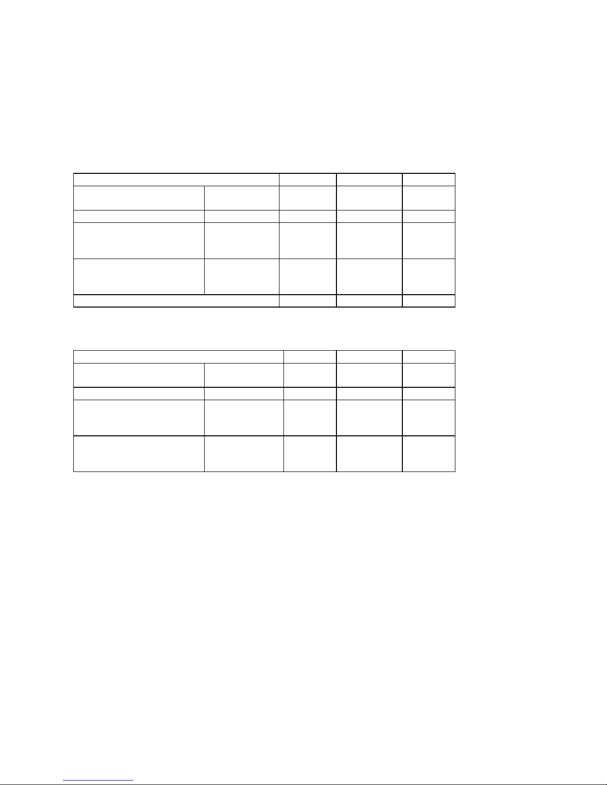
SPECIFICATIONS
Power source : AC 230V
Load impedance : 4 ohm
Reference output : 50 mW
BAND: AM 1 kHz 30% MOD.
Characteristic Unit Nominal Limit
Frequency
Range
Low
High
kHz
kHz
525
1645
±25
±30
Intermediate Frequency kHz 455 ± 2
20 dB S/N
Sensitivity
1000 kHz 600
kHz
1400 kHz
dB/M
dB/M
dB/M
61
60
61
65
66
65
S/N at 5 mV/m Input
600 kHz
1000 kHz
1400 kHz
dB
dB
dB
45
45
45
40
40
40
Selectivity ± 10 kHz dB 35 ± 20
BAND: FM 1 kHz 22.5 kHz DEV.
Characteristic Unit Nominal Limit
Frequency
Range
Low
High
MHz
MHz
87.5
108.5
±0.5
±0.5
Intermediate Frequency MHz 10.7 ± 0.1
30 dB S/N
Sensitivity
90 MHz
98 MHz
106 MHz
dB/M
dB/M
dB/M
18
18
18
23
23
23
S/N at 1MV
Input 22.5 kHz
Deviation
90 MHz
98 MHz
106 MHz
dB
dB
dB
45
45
45
40
40
40
Page 4
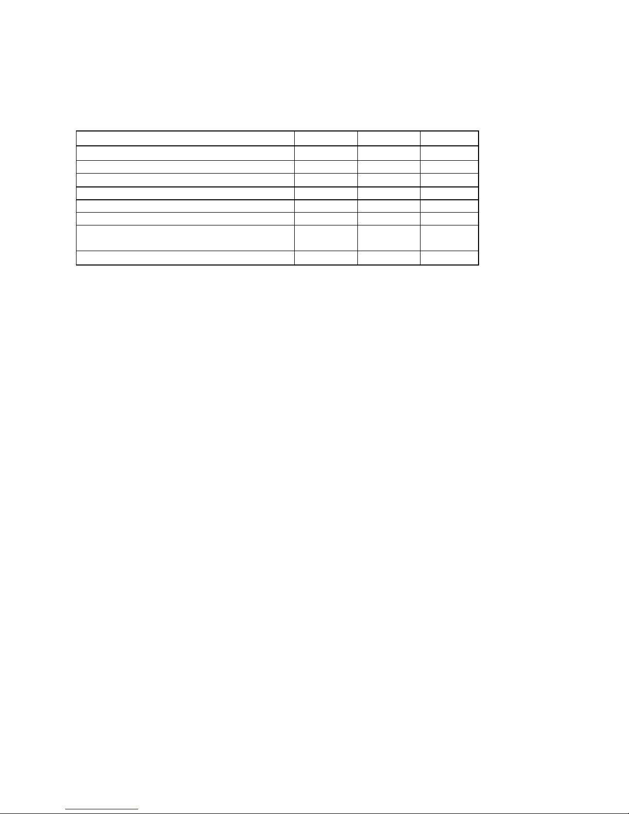
CD
Item Unit Nominal Limit
Frequency Response 100 Hz dB -3 ±3
20kHz dB -3 ±3
S/N W/IEC-A & LPF. dB 50 40
Interruption µm 1000 600
Black Dot µm 800 600
Eccentricity µm 70
Channel Separation (W/Band Pass Filter) dB 35 30
Page 5
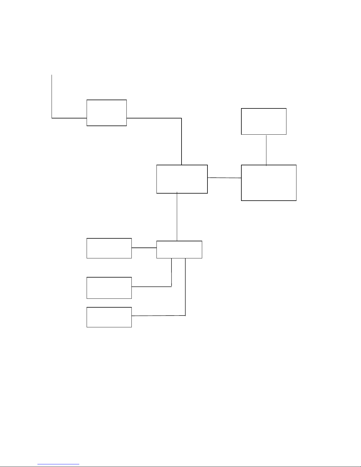
BLOCK DIAGRAM
ANT
IC1
AM/FM
TA2111
FUNCTIONS
TRANSITION
POWER
AMP IC7
TA8227
SPEAKER
L/R
CD SERVO
CD MECH
KEY
LCD
Page 6
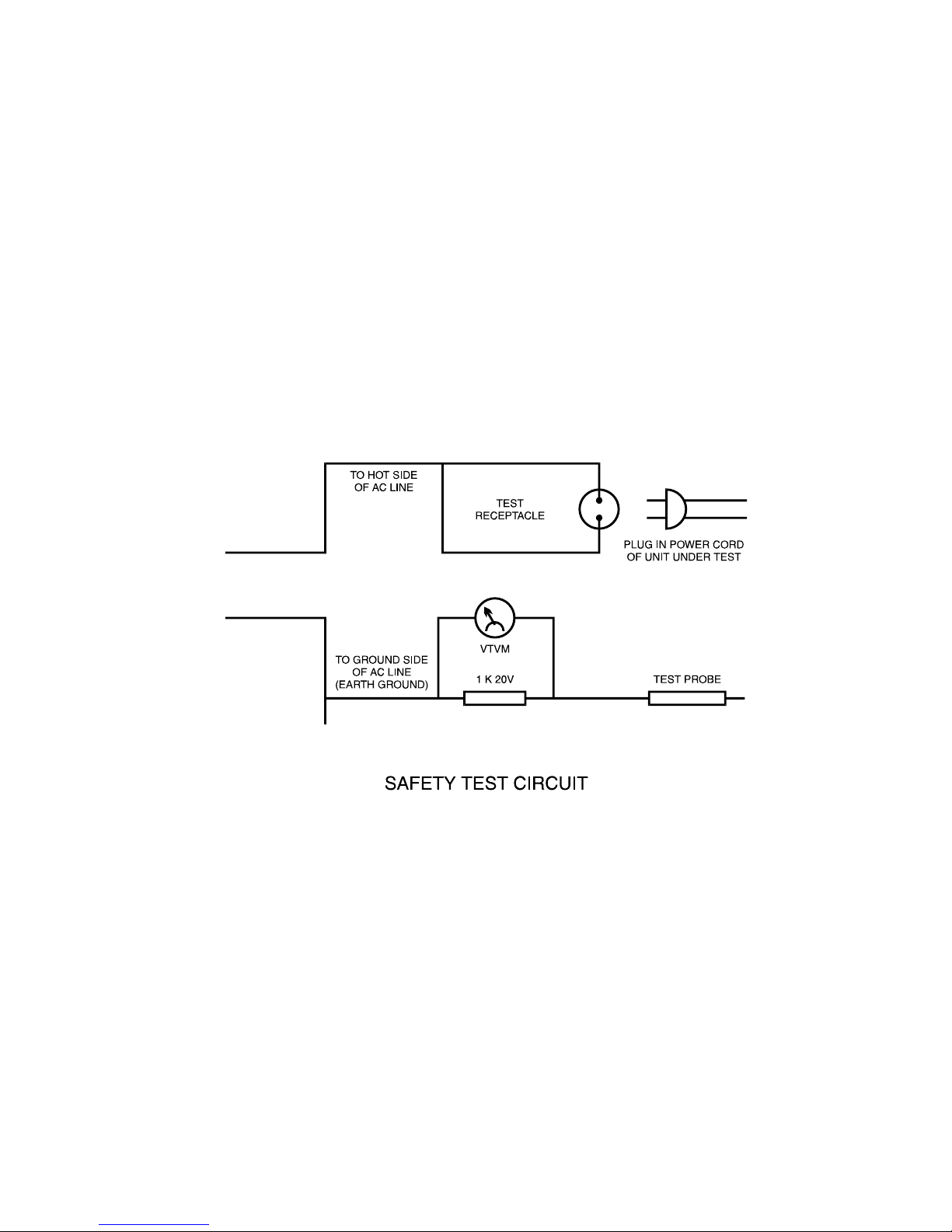
SAFETY CHECKS
Important Note!!! Do the following safety checks after servicing this unit.
1. Remove all the externally connected test equipment and wires before testing the unit.
2. Use the safety test circuit as shown below.
3. Plug the power cord or unit to be tested into the test receptacle.
4. Switch the unit being tested to ON or PLAY.
5. Connect external jack/terminal contact VTVM across a 1k resistor in the test circuit. Set the meter to a
high (150V AC) scale to avoid meter damage and then touch the points with the test probe.
If the meter reading indicates less than 3 volts on all test points, set the meter to a low (3V AC) scale
and repeat the test.
6. Any reading greater than 0.2 volt indicates a potential shock hazard. If this occurs, determine the
cause of the leakage, correct the problem, and repeat the safety test.
Page 7

CD PLAYER CHECKING PROCEDURES
AA.. WWAAVVEE EE//FF BBAALLAANNCCEE AADDJJUUSSTTMMEENNTT
1) Test Point : VC, TS10.
2) Test Disc : Sony Test CD Type 3.
3) Test Equipment :
Scope : DC 0.2 V 0.5 ms.
4) Test Mode : Play Sony CD, Type 3, Track 1, Press FF.
(Fast Forward), Adjust VR401 Until A=B (as Figure Bellow).
SCOPE : DC POSITION
A
B
Figure A
B. FOCUS-BIAS ADJUSTMENT
1) Test Point : VC RFO.
2) Test Disc : Sony Test CD, Type 3.
3) Test Equipment :
Scope : DC 0.5 V 0.5 μs.
SCOPE : AC POSITION
Page 8

TROUBLESHOOTING
Circuit Symptom Cause and Remedy
General No sound
• Speakers are not connected:
Check the speaker connection.
• Wrong function is selected:
Set switch to the proper position.
• Defective volume control:
Set the volume control to a proper sound level.
• Defective earphone jack:
Replace the earphone jack.
• Mute function is active:
Release it by remote control.
AM No sound, weak sound
(Low sensitivity)
• Improper location of unit:
Rotate or reposition the unit.
• Defect AM antenna coil or oscilloscope coil:
Replace if necessary.
• Intermediate Frequency tuning faulty:
Readjust (see “Alignment and Adjustment”).
• RF tracking faulty:
Readjust (see “Alignment and Adjustment”).
• Defective TA2111
Check voltages. Replace if necessary.
• Poor contact in antenna circuit:
Check resistance and resolder.
FM No sound, weak sound
(Low sensitivity)
• FM antenna not connected:
Connect the built-in or external antenna.
• Defective band selector switch:
Replace or repair the switch.
• Defective TA2111:
Check voltages. Replace if necessary.
• Intermediate Frequency tuning faulty:
Readjust (see “Alignment and Adjustment”).
• Poor contact in FM antenna circuit:
Resoled or repair as required.
CD Cannot read the table of
contents,
no display,
no sound.
• Disc is inserted upside down:
Insert disc correctly.
• Disc is dirty:
Wipe clean with a soft cloth.
• Disc is scratched:
Use a new disc.
• Disc is seriously warped:
Use a new disc.
• A non-standard disc has been inserted:
Use only a brand name disc.
• Moisture has formed inside the CD Pick-up Head:
Wait about 20 to 30 minutes.
• Defect in the servo control board:
Replace or repair as required.
• Defect in the pickup mechanism:
Replace as required.
Page 9

Page 10

Page 11

Page 12

Page 13

Page 14

EXPLODE VIEW
BATTERY TERMINAL
SPEAKER CLIP
DUST PROOF COVER
CD MECHANISM
CD DOOR LENS
CD KNOB
LCD LENS
LCD BRACKET
CD DOOR
SPEAKER
FUNCTION KNOB
FRONT CABINET
TUNING GEAR
MID-CABINET
BOTTOM CABINET
PCB
DIAL DRUM
BATTERY DOOR
AC COVER
TRANSFORMER
PVC KNOB
AC SOCKET
SPEAKER GRILL
AM BAR BRACKET
PVC SHAFT
DIAL SPRING
FM
ANTENNA
LCD LENS
RING
Page 15

Index Part Name Description Unit Qty Remarks
1 PCB WH729MP3-M REV-B pcs 1 TH=1.6
2 WH729MP3-D REV-B pcs 1 TH=1.0
3 WH-MP3-REMOTE REV-2 TH=1.0 pcs 1 35*58MM / 94HB / CX050-052
5 Resistor (SMD 0603) 0R pcs 6 C77 C80 R20 RJ14 RJ17 RJ6
6 100K pcs 6 R13 R62 R63 R80 R85 R89
7 100R pcs 1 R131
9 10R pcs 3 R40 R46 R45
10 120R pcs 2 R57 R58
11 12K pcs 4 R44 R70 R71 R96
12 150R pcs 4 R79 R87 R101 R102
13 15K pcs 1 R25
14 18K pcs 4 R76 R77 R60 R61
15 180K pcs 4 R126 R127 R128 R129
16 1K pcs 6 R5 R27 R29 R30 R43 R53
17 220K pcs 2 R66 R67
18 220R pcs 3 R10 R37 R84
19 22K pcs 6 R3 R14 R41 R113 R114 R120
20 2.2K pcs 3 R4 R18 R39
21 2.2M pcs 2 R9 R23
22 33K pcs 1 R124
23 39K pcs 2 R36 C78
24 3.9K pcs 2 R47 R117
25 3.3K pcs 1 R82
26 470K pcs 1 R24
27 470R pcs 2 R93 R100
28 47K pcs 3 R28 R65 R59
29 47R pcs 2 R94 R115
30 4.7K pcs 6 R31 R33 R56 R95 R116 R118
31 560R pcs 1 R21
32 4.7R pcs 1 R68
33 56K pcs 4 R109 R110 R111 R112
34 56R pcs 1 R92
35 5.1K pcs 2 R72 R73
Bill of Materials
RJ9 RJ10 RJ5 RJ7 RJ8 RJ11 RJ12 RJ13
RJ15 RJ16 RJ18 RJ19 RJ20 RJ21 RJ22
RJ23 RJ24 RJ25 RJ26 RJ27 RJ28 RJ29
RJ30 RJ31 RJ32 RJ33 RJ34 RJ35
28pcs0RResistor (SMD 1206)4
pcs10K
R2 R8 R11 R12 R15 R17 R32 R35 R38
R42 R48 R49 R50 R52 R64 R69 R74 R75
R97 R103 R104 R121 R122 R123 RJ1 RJ2
R34
8 27
Page 16

36 5.6K pcs 1 R22
37 680R pcs 1 R106
38 68K pcs 1 R88
39 6.8K pcs 4 R16 R51 R83 R119
40 82K pcs 2 R125 R130
41 8.2K pcs 2 R107 R108
42 Resistor (DPI) 150R 1/4W pcs 2 R26 R105
43 470R 1/4W pcs 1 R90
44 4.7K 1/16W pcs 1 R97
45 3.3R 1/4W pcs 2 R54 R55
46 Ceramic Cap (SMD 0603) 102P pcs 3 C68C69C148
47 103P pcs 8 C30 C51 C74 C75 C88 C94 C106 C147
49 203P pcs 8 C76 C81 C99 C107 C10 8C109 C110 C113
50 222P pcs 4 C46 C47 C149 C151
51 272P pcs 1 C134
52 333P pcs 2 C139 C141
53 472P pcs 1 C140
54 473P pcs 7 C132 C154 C158 C160 C67 C70 C157
55 502P pcs 2 C71 C72
56 100P pcs 3 C20 C36 C48
57 10P pcs 2 C97 C101
58 150P pcs 1 C112
59 153P pcs 1 C50
60 15P pcs 3 C100 C144 C145
61 222P pcs 1 C38
62 22P pcs 1 C93
63 25P pcs 1 C92
64 30P pcs 4 C83 C84 C85 C102
65 330P pcs 1 C90
66 3P pcs 3 C26 C96 C137
67 470P pcs 2 C155 C156
68 47P pcs 1 C52
69 500P pcs 2 C63 C64
70 56P pcs 2 C13198
71 5P pcs 1 C87
72 E. Cap 0.47UF/50V pcs 1 C82
73 1000UF/25V pcs 2 C19 C54
74 100UF/16V pcs 5 C1 C15 C58 C59 C66
C11 C22 C23 C40 C44 C118 C119 C120
C121 C127 C128 C129 C130
1UF/50V
C18 C21 C29 C32 C33 C34 C35 C37 C41
C42 C43 C45 C49 C65 C89 C91 C95 C133
C135 C136 C138 C142 C143 C146 C150
C152 C153 C159
28pcs104P48
75 13pcs
Page 17

76 2200UF/25V pcs 1 C111
77 220UF/16V pcs 5 C16 C17 C61 C73 C86
78 22UF/10V pcs 1 C10
79 3.3UF/50V pcs 2 C12 C9
80 470UF/25V pcs 3 C53 C55 C124
82 4.7UF/50V pcs 3 C79 C125 C126
83 Filter 10.7 (3-pin) pcs 1 CF1
84 10.7 (2-pin) pcs 1 CF3
85 455K pcs 1 CF2
86 Crystal 16.93MHZ pcs 1 X1
87 Transistor 882 pcs 1 Q18
88 Transistor (SMD) 9014 pcs 6 Q3 Q4 Q6 Q7 Q11 Q12
89 9015 pcs 3 Q2 Q5 Q8
90 9018 pcs 4 Q13 Q14 Q15 Q16
91 Choke Coil 10UH pcs 3 L7 L8 R81
92 15UH pcs 5 L1 L2 L9 L10 L11
93 PVC 126:20 pcs 1 PVC1
94 AM Bar L:60 mm pcs 1 AM Antenna
95 Mylar Cap 224M pcs 2 C56 C57
96 Zener Diode 3.0V/0.5W pcs 1 ZD5
97 4.3V/0.5W pcs 1 Z1
98 4.7V/0.5W pcs 1 ZD2
99 8.2V/1W pcs 1 ZD3
100 FM Coil 4.5*2T5*0.7 pcs 1 L6
101 4.5*3T5*0.8 pcs 1 L5
102 4.5*4T5*0.8 pcs 1 L4
103 IFT RED pcs 1 T1
104 YELLOW pcs 1 T2
105 Volume R1216G-OKD1-B50K pcs 1 VR1
106 Ferrite Coil 9*5*3MM pcs 1 L12
107 Diode IN4001 pcs 7 D3 D4 D5 D6 D7 D8 D13
108 IN4148 pcs 6 D1 D2 D9 D10 D11 D12
109 IC AUK-S30011 pcs 1 U6
110 B1117 pcs 1 U2
111 MM1571F pcs 1 U1
112 TA2111N pcs 1 IC2
113 TA2157FN pcs 1 U3
114 TA8227 pcs 1 IC1
115 TC94A34FG-002 pcs 1 U5
116 TC94A58FAG-050 pcs 1 U4
117 Phone Jack 3507202 pcs 1 JK1
C2 C3 C4 C5 C6 C7 C8 C13 C14 C60 C62
C103 C105
13pcs47UF/16V81
Page 18

118 Touch Switch 6 x 6 x 5 pcs 8
119 Speaker 2.5" 4Ω3W pcs 2
120 CD Mechanism SANYO pcs 1
121 CD Mech. Rubber 20° (Yellow) pcs 4 CD mechanism
122 Transformer EI-41 9V pcs 1
Current ≥800MA
123 AC Socket with Switch pcs 1
124 110/220 Switch SS12J01 pcs 1
125 Band Switch SK44D04GB pcs 1 SW7
126 Am Antenna 115:15 L:80 mm pcs 1
127 AC Cord pcs 1
128 CD Door Switch 04 Type pcs 1
129 Eyelet pcs 3
130 Rubber Tube 3.5 dia. x 25 pcs 3 AC convert switch
131 Metal Washer 14 dia. x dia 3 x 1 (mm) pcs 4 CD mechanism
132 LCD Board pcs
133 Resistor (SMD 1206) 0R pcs 1
134 Resistor (SMD 0603) 0R pcs 3
135 220R pcs 1
136 C. Cap (SMD 0603) 20P pcs 2
137 104P pcs 2
138 203P pcs 1
139 5P pcs 2
140 103P pcs 1
141 E. Cap 47UF/16V pcs 1
142 IR 3V pcs 1
143 LCD HD42909-3 pcs 1
144 Crystal 32.768KHZ pcs 1
145 LED 3MM pcs 1
146 IC SC3610 pcs 1
147 Resistor (SMD 0603) 6.8K pcs 1
148 15K pcs 1
149 3.9K pcs 1
150 43K pcs 1
151 1.5K pcs 1
152 2.7K pcs 1
153 2K pcs 1
154 100P pcs 1
155 Speaker Clip sets 1
156 Heat Sink TA8227 pcs 1
157 Battery Spring 729 sets 1
158 CD Door Spring pcs 1
159 Speaker Grill Left & Right sets 1
160 Antenna FM Antenna pcs 1 (R=6mm) 1602C
Page 19

161 Dial Spring 2.0 dia. x 12 pcs 1 PVC Knob
162 Screws 3 x 5 PM pcs 1 Antenna
163 3 x 10 PWA pcs 4 AC Socket
164 3 x 10 PA pcs 14 Transformer
165 2 x 8 PA pcs 4 CD x 4, spkr x 4, cab x 4, handle x 2
166 3 x 12 PA pcs 2 Key
167 2.6 x 12 PA pcs 2 Bottom
168 2 x 8 PA pcs 1
169 2.3 x 6 PA pcs 4 CD Door Switch
170 3 x 8 PA pcs 6 LCD Board
171 2.6 x 4 KA pcs 2 PCB
172 2.6 x 6 PM pcs 1 Securing PVC
173 3 x 8 PA pcs 1 PVC
174 1.4 x 2.5 PWB pcs 6 Line in Bracket
175 2 x 5 PWA pcs 2 LCD Lens
176 2.6 x 5 PM pcs 1 CD Lens
177 Sponge 12 x 5 x 5 mm pcs 1 CD Door
178 25 x 10 x 1 mm pcs 1 LCD PCB
179 Sponge (White) 55 x 45 x 6 mm pcs 1 Battery
180 Sponge 15 x 10 x 10 mm pcs 1 AM Bar
181 Plastic Parts Front Cabinet pcs 1
182 Back Cabinet pcs 1
183 CD Door pcs 1
184 LCD Bracket pcs 1
185 LCD Ring pcs 1
186 CD Lens pcs 1
187 PVC Knob pcs 1
188 Function Knob pcs 1
189 Dial String pcs 1
190 CD Knob pcs 1
191 AM Bar Bracket pcs 2
192 Mid Cabinet pcs 1
193 Battery Door pcs 1
194 AC Cover pcs 1
195 Line Bar pcs 1
196 LCD Lens pcs 1
197 Packing Rating Label pcs 1
198 CD Lazer Label pcs 1
199 Transformer Label pcs 1
200 Date Code Label pcs 1
201 Pplyfoam pcs 1
202 Gift Box pcs 1
203 Adhesive Tape pcs 1
Page 20

204 Poly Bag pcs 1
205 Export Carton pcs 1
206 Pin Wire 16P x 300 x 1.0mm pcs 1 CD to PCB
207 6P x 85mm x 2.0mm pcs 1 CD to PCB
208 FCC Pins 19P x 100mm x 1.0mm pcs 1 LCD to PCB
209 3P x 250mm x 2.0mm pcs 1
210 3P x 100mm x 2.0mm pcs 1 CD Function key to PCB
211 5P x 140mm x 2.5mm pcs 1 UL 2651 Aux to PCB
212 UL 1007#26 2P x 100 x 2.0mm pcs 1 CD Door Switch to PCB
213 UL 1007#22 250mm pcs 2 White , Black
214 UL 1007#22 500mm pcs 1 Red
215 UL 1007#22 250mm pcs 1 Black
216 UL1007#22 320mm pcs 1 Green
217 UL1007#22 300mm pcs 1 Battery (+) to PCB
218 UL1007#22 200mm pcs 1 AC Socket to PCB
219 UL1007#22 80mm pcs 1 AC Socket to B (+)
220 Remote PCB R-5K pcs 1 94HB
221 IC SC9243S pcs 1 IC7
222 Transistor H9014 pcs 1 Q11
223 IN4148 pcs 1 D8
224 pcs 1 D9
225 Crystal 455E pcs 1 CF3 2PINS
226 Elect Cap 100uF/10V pcs 1 C161
227 Resistor 6.8K pcs 1 R174
228 100P pcs 2 C162 C163
229 Touch Switch 6*6*5 pcs 5
230 Battery Terminal sets 1
231 TAPE 40x40x0.25mm pcs 1
232 Screw 2 x 6 PA pcs 4
233 Cabinet sets 1
234 Buttons sets 1
235 Lens pcs 1
Remote Control Version only
 Loading...