


R
- CD-910DVD
- CD-910DVD
CD-910DVD
Service Manual
Service Manual


CONTENTS
Page
Disassembly Instructions ..................................................................................................................................... 3
Disassembly Diagram.......................................................................................................................................... 4
Operation Check..................................................................................................................................................5
Block Diagram ..................................................................................................................................................... 6
Alignment Locations ............................................................................................................................................7
Alignment Procedures .........................................................................................................................................8
Printed Circuit Boards........................................................................................................................................ 10
Wiring Diagram .................................................................................................................................................. 17
Exploded Views (Panel)..................................................................................................................................... 18
Exploded View Parts Lists (Panel)..................................................................................................................... 19
Exploded Views (Cabinet) ................................................................................................................................. 20
Exploded View Parts Lists (Cabinet) ................................................................................................................. 21
Schematic Diagram ...........................................................................................................................................23
Electrical Parts List ............................................................................................................................................ 29
Specifications..................................................................................................................................................... 34
2

DISASSEMBLY INSTRUCTIONS
1. Using the unlock key that came with the unit or a similar tool, unlock the mounting box and remove toward the
Rear of the unit.
2. Remove two screws (A) located on the Cabinet Top then remove the Cabinet Top.
3. Remove two screws (B) located on the Cabinet Bottom then remove the Cabinet Bottom.
4. Remove two screws (C) (one located at the left side and one located at the right side of the front cabinet) then
remove two Hooks.
6. Remove the screw (D) from on the left side of the left bracket and remove the screw (E) from on the right side
of the right bracket.
7. Remove two screws (F) from on the rear bracket then remove the Deck.
8. Take Out the Panel and the Ring.
Remove two screws (G) from each side of the base then remove the Base.
9. Remove two screws (H) from on the right bracket then remove the Tooth Bracket and the Tune Top Tooth.
Slide off the Nut and the Stop Washer then remove the Brass Bush and the Tuning Shaft /Tuner.
9. Remove the screw (I) and two screws (J) from on the right bracket then remove the Tune FIX Support.
Remove the screw (K) from on the right bracket and remove three screws (L) from under the right bracket and
remove the 2BND Tuner and the Tuner Support.
10. Remove two screws (M) from on the back of the rear bracket and Slide off two Nuts then remove the DC FAN
12V.
Remove five screws (N) from on the back of the heat sink then remove the Heat Sink and the Heat Sink
Adaptor.
Remove two screws (O) from on the back of the rear bracket then remove the 22PIN Socket.
11. Remove the screw (P) from on the left bracket then remove the Transistor Holder.
12. Remove three screws (Q) from under the main board then remove the Main Board.
13. Remove two screws (R) from on the left bracket then remove the Left Bracket.
14. Remove two screws (S) from the right bracket then remove the Right Bracket and the Rear Bracket.
3
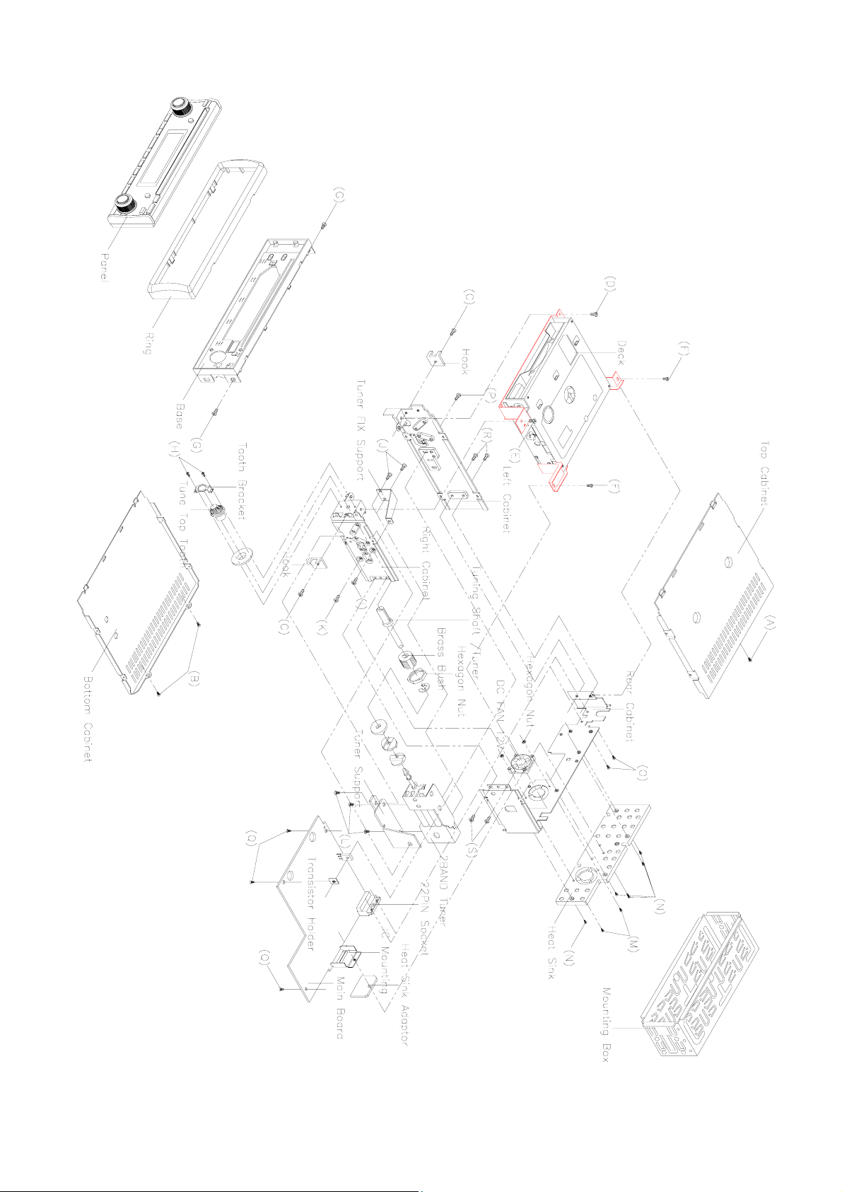
DISASSEMBLY DIAGRAM
4
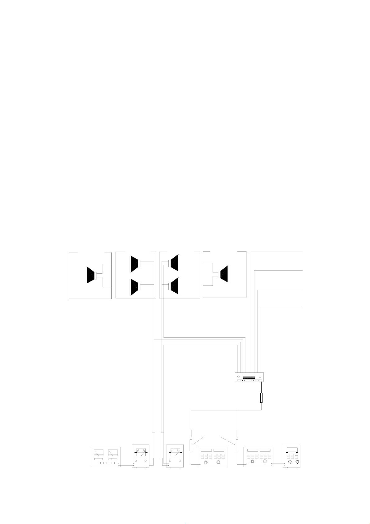
OPERATION CHECK
GENERAL SPECIFICATIONS OF SIGNAL
Standard frequency
Signal output
Modulation
FM
MW
FM
MW
MW
FM Stereo
98.1 MHz (87.5, 108 MHz)
1000 kHz (522, 1620 kHz)
1 mV
5 mV
400 Hz 30% MOD.
1 kHz 75 kHz DEV.
46% for L only or R
only pilot level 8%.
AF output level FM/MW
Power source voltage DC 14.4V (Backup voltage is the same as this)
AF load impedance 4 ohm pure resistance
Balance Center position of level
Tone Center position.
The signal strength read in this section is voltage on the antenna.
Test Diagram
2-SPEAKER
FRONT
SPK.
4-SPEAKER
RL.
SPR.
FL.
SPK.
4-SPEAKER
RR.
SPK.
FR.
SPE.
2-SPEAKER
FRONT
SPK.
ACC (DV14.4V)
BACK UP (14.4V)
GROUND
POWER ANTANNA
MAIN UNIT
ANT
MPX
STEREOS
MODULATOR
DISTORTION
METER
VTVM
VTVM
DUMMY
ANTANNA
AM SG
FM SG
5
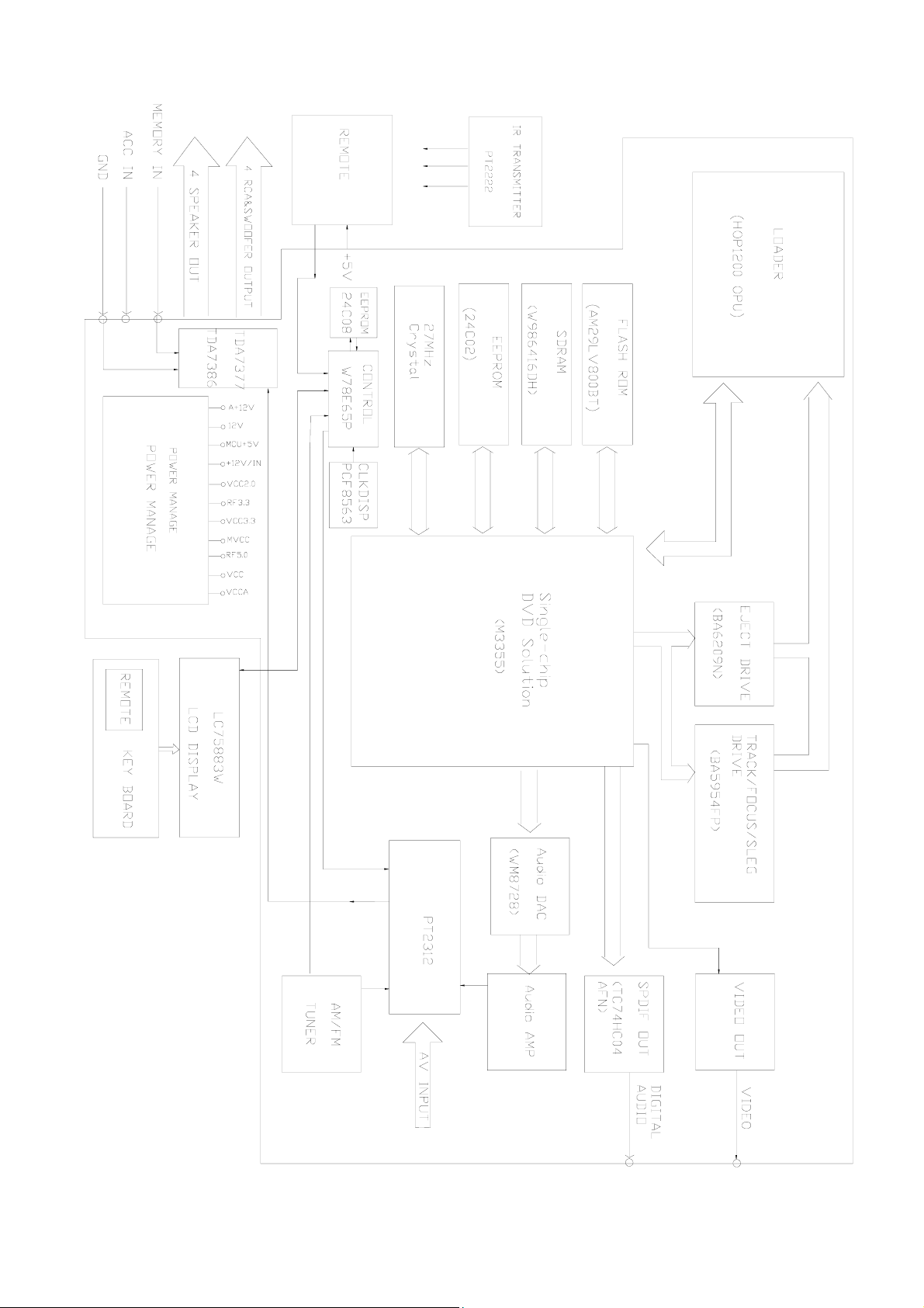
BLOCK DIAGRAM
6

ALIGNMENT AND PROCEDURES
FM IF/RF ADJUSTMENT
Equipment required
● FM IF/RF signal generator
● Oscilloscope
● FM Stereo signal generator
● Solid-state voltmeter (SSVM)
● Regulated DC power supply
● Distortion meter
FM IF and RF Alignment Using FM Signal Generator
Note: Press the radio power switch to on the radio. Signal generator output must be kept as low as possible to
avoid overload and dipping
Step Generator
Coupling
Generator
Setting
Display
Setting
Adjustment Remark
IF FM RF signal
Generator to
Antenna
Input.
76 kHz pilot
Modulation
Stereo
Separation
Note: The tuner module is well-aligned and adjustment is not recommended
Signal generator
to antenna
receptacle
Signal
Generator to
antenna
10.7 MHz
Sweep output
30dB/µV
75 kHz Dev.
90% for L only
or R only pilot
level 10%
98.1 MHz
int. 1 kHz
Dev. 75 kHz
L + R = 92%
Pilot = 8%
98.1 MHz T102 Adjust so that
98.1 MHz VR2 Adjust to
98.1 MHz VR1 Adjust AF
maximum AF
output power and
minimum
distortion
76 kHz
Output power
For maximum
Separation
7

AM IF/RF ADJUSTMENT
Equipment required
z AM IF/RF signal generator
z Solid-state voltmeter (SSVM)
z Regulated DC power supply
z 2-CH voltmeter
z Distortion meter
AM IF and RF Alignment Using AM Signal Generator
Note: Press the power switch to on the radio. Signal generator output must be kept as low as possible to avoid
overload and clipping
Step Generator
Coupling
IF AM RF
Signal
Generator to
Antenna.
FREQ.
Low
FREQ.
High
RF Signal
RF
Count
530 kHz
Generator
to antenna
receptacle
Signal Generator
To antenna
receptacle
Note: The tuner module is well-aligned and adjustment is not recommended.
Generator Display
Setting
450 kHz Sweep
Output
60dB/µV
600 kHz Int.
400Hz 30%
Mod output
20dB/mV
1000kHz Int.
400Hz 30% mod.
Output 20 dB/mV
530 kHz T101 Adjust so that
1710 kHz
600 kHz T107
1400 kHz VC101 Adjust AF output
Adjustment Remark
T106
CT103
CT102
maximum left and
right are
symmetrical
Adjust AF output
power for
maximum
power for
maximum
8
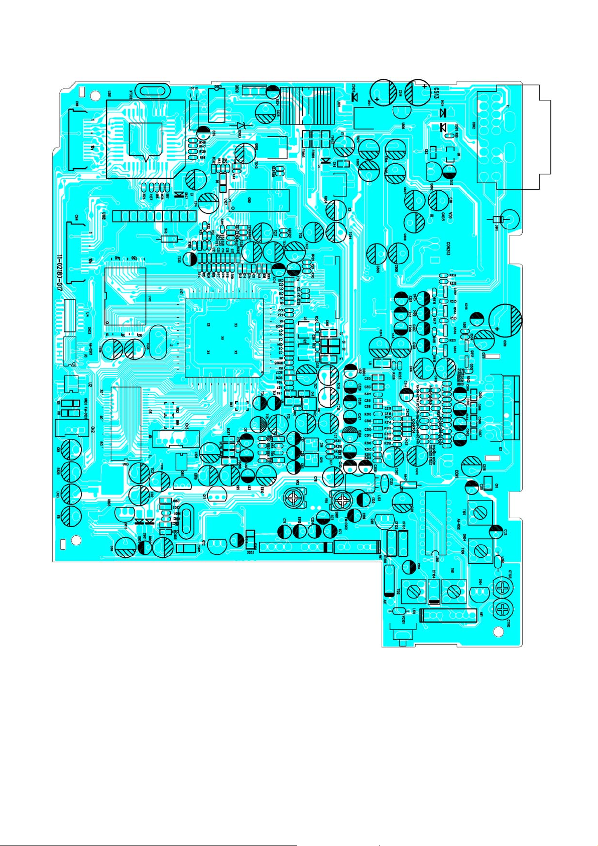
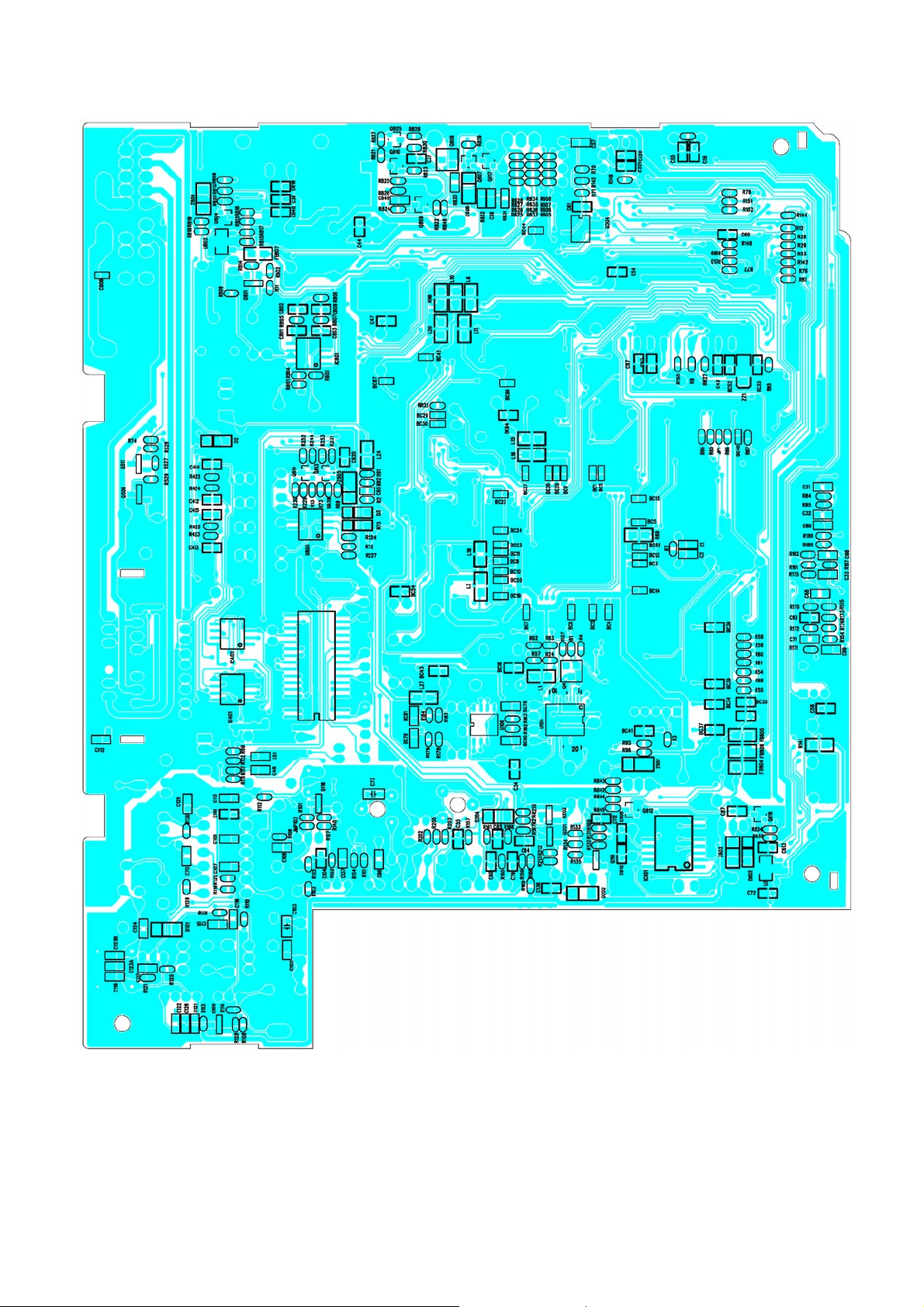
MAIN BOARD
PRINTED CIRCUIT BOARDS
TOP VIEW
9
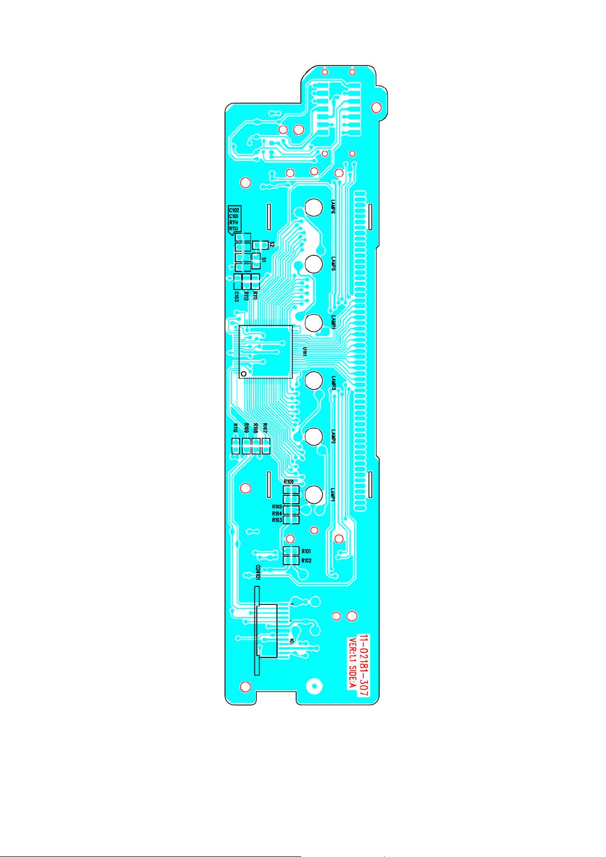
MAIN BOARD
BOTTOM VIEW
10
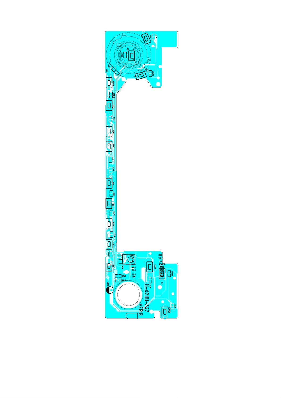
KEY BOARD
TOP VIEW
11
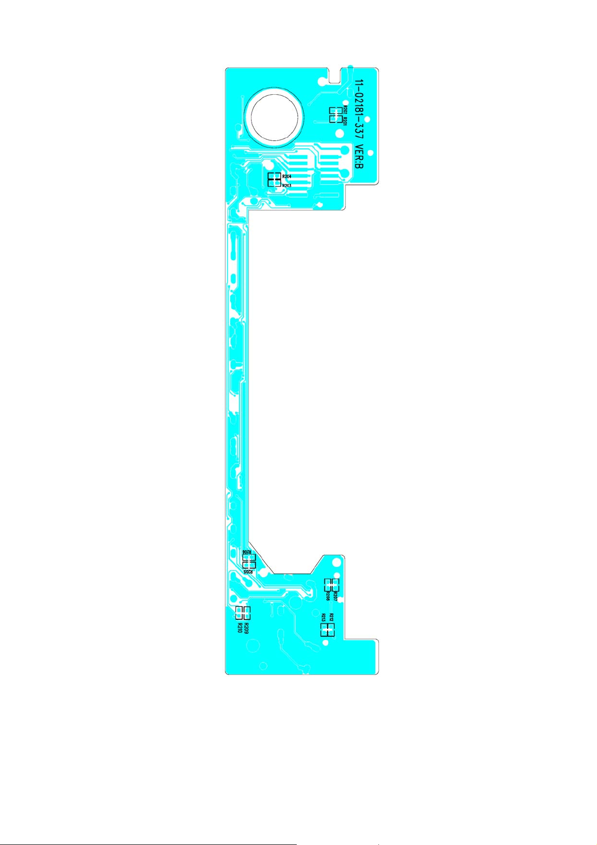
KEY BOARD
BOTTOM VIEW
12
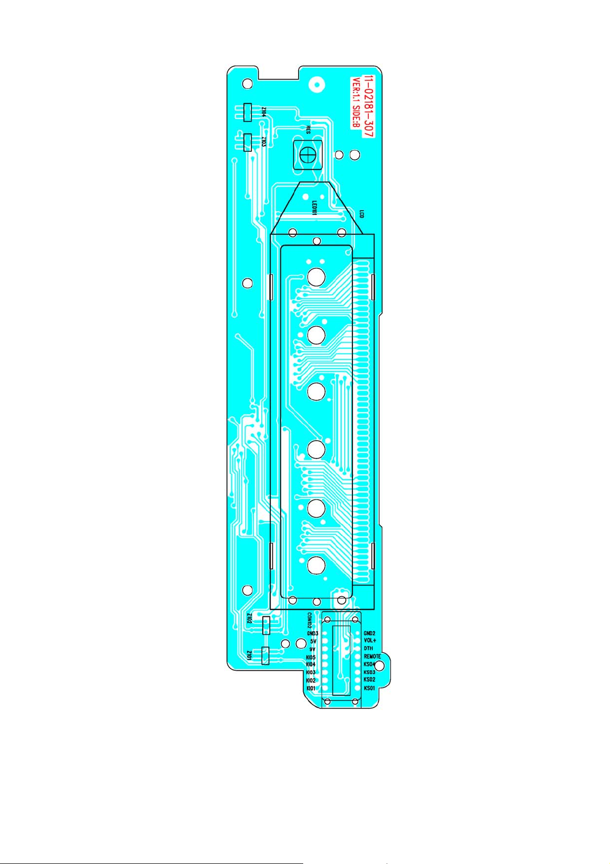
DISPLAY BOARD
TOP VIEW
13
DISPLAY BOARD
BOTTOM VIEW
14

REMOTE BOARD
TOP VIEW
15

REMOTE BOARD
BOTTOM VIEW
16

WIRIN DIAGRAM
17

PANEL
EXPLODED VIEW
18

EXPLODED VIEW PARTS LIST
PANEL
Ref. No. Description RS Part No. Mfr’s Part No.
1
2
3
4
5
6
7
8
9
10
11
12
13
14
15
16
17
18
Lens; DVD218 RM/SW (S. OP1202) ROADSTAR
Top Panel (S. OP1202)
Panel Bottom For LED Back Light 777D
Tuning Knob (S. OP1202)
TUNE Bottom Tooth
Encode Knob (S. OP1202)
SEL Knob (S. OP1202) (L-Up)
Spring Ring
EQ/DSP Knob (L-Up) (S. OP1202)
MODE/RDM/MON Knob (S. OP1202) (L-Up)
BND/EJ/PWR Knob (L-Up) (S. OP1202)
REL Knob (S. OP1202)
RE Knob Spring
Back Light For EQ/DSP Knob SPY WHT
Key Board
Encoder SRGP200200 (ALPS)
Screw Ø2.6X6 PH/ST Black
Screw Ø2X8 BH/ST Black
53-C1844-819
51-C1824-80S
51-C1826-00
52-C1833-80S
52-C1839-00
52-C1832-80S
52-C1828-82S
52-C1842-00
52-C1829-81S
52-C1827-86S
52-C1830-81S
52-C1831-80S
36-11852-00
52-C1834-01
11-02180-337
18-00163-00
40-12606-20
40-12008-01
19

CABINET
EXPLODED VIEW
20

EXPLODED VIEW PARTS LIST
CABINET
Ref. No. Description RS Part No. Mfr’s Part No.
1
2
3
4
5
6
7
8
9
10
11
12
13
14
15
16
17
18
19
20
21
22
23
24
25
26
27
28
29
30
31
32
33
34
35
36
37
38
39
40
Panel
Ring (S. OPC1202)
Base For LED Back Light 777D
Right Cabinet
Left Cabinet
Rear Bracket (V) 1.0MM G.S.S.
Cabinet Top
Bottom Cabinet
CD MECH. SLOT TYPE (HOP-1200W) WITH CONVERT
Heat Sink (V) 3.0 AL.
Main Board
Main Fiber (FOR DVD)
Mounting Box 60C
Shade
CD Windows Sheet
LCD Cover For LED B-L
DVD218 LCD Black MASK 83X21.5MM
CD1007 B.LIGHT /WHITE
LED Support (M)
Display Board
16PIN Socket
Spring Block
RE Knob Spring
Hook
Lock Spring (Ø0.4)
Hook
Tooth Bracket (Black)
TUNE Top Tooth
TUNE Spring Ø0.8
Tuning Shaft /Tuner
Brass Bush OPC128-52
2BANDS Tuner MGJ03CE-1B4.5T (7640)
Tuner Support
Tuner FIX Support
Deck Front Bracket 1.0MM G.S.S.
Deck Rear Bracket (R)
Deck Rear Bracket (L)
Transistor Holder/Philips 0.8MM
22PIN Socket JENSEN MCC8526
IC Mounting (TDA7375)
51-C1823-80S
51-C1822-00
61-C1803-00
61-C1817-00
61-C1814-00
61-C1801-01
61-C1818-00
94-02682-00
61-C1815-00
11-02180-017
35-C1804-00
61-02905-00
81-69005-02
43-A3101-00
39-C1808-00
27-21800-03
02-01007-09
52-E2042-00
11-02181-307
25-F0218-16
52-C1838-00
36-11852-00
52-C1837-00
36-C1801-01
39-C1806-00
39-C1803-01
52-C1840-00
36-08002-00
34-05602-00
34-12852-00
29-30031-15
39-C1801-01
39-C1802-01
39-C1812-00
39-C1821-00
39-C1822-00
39-68721-00
25-F0180-20
39-73751-01
21

Ref. No. Description RS Part No. Mfr’s Part No.
41
42
43
44
45
46
47
48
49
50
51
52
53
54
55
Heat Sink Adaptor (4.0MM)
DC FAN 12V 30X30X7
Hexagon Nut M2.6
Spring Washer M5
Back Mounting Screw
Screw Ø2 X 4 PH/ST
Screw Ø2.6 X 4 PH/MS
Screw Ø2.6 X 4 BH/MS
Screw Ø2.6 X 4 KH/MS
Screw Ø2.6 X 4 PH/TAPTITE
Screw Ø2.6 X 6 BH/MS
Screw Ø2.6 X 8 BH/MS
Screw Ø2.6 X 10 BH/ST
Screw Ø2.6 X 14 BH/ST
Screw Ø3 X 5 KH/MS
39-C1823-00
49-03012-12
35-40026-00
35-50001-00
34-68701-00
40-02004-05
40-02604-00
40-02604-01
40-02604-02
40-02604-03
40-02606-01
40-02608-01
40-02610-01
40-02614-01
40-03005-03
22

SCHEMATIC DIAGRAM (MAIN BOARD) (MTR+AMP)
23

SCHEMATIC DIAGRAM (MAIN BOARD) (MCU)
24

SCHEMATIC DIAGRAM (MAIN BOARD) (DVD)
25

SCHEMATIC DIAGRAM (MAIN BOARD) (POWER)
26

SCHEMATIC DIAGRAM (KEY & DISPLAY BOARD)
27

SCHEMATIC DIAGRAM (REMOTE BOARD)
28

ELECTRICAL PARTS LIST
Ref. No. Part No. Description Q’ty
PC BOARD ASSY, MAIN BOARD
Q1
Q609
Q202,511,801
Q2,3
Q808
Q813/4
Q109,110/6,201,501~5/9,511
Q804/6/9,810/2/6/7
Q12
Q807
Q111,802,815
Q112,805,811
Q104
Q101
D1,504,604/7
D2~11/3/4,101,202~4,602,801/2,RN5
R75
D901
ZD607
ZZ1
Z605
Z604
Z601/2/6
ZD603
U801
U803
U804
U805
IC604
U105
U304
U101
U4
U401/2,801
U106
U107
U201
IC201
01-00231-00
01-00435-00S
01-00812-00
01-01132-00
01-01385-00
01-03265-00
01-03875-07
01-03904-00
01-03906-00
01-04375-00
01-08050-03
01-08550-03
01-09011-07S
01-09018-07S
02-04001-01
02-04148-02
02-05401-00
02-05819-02
02-50043-00
02-50051-03
02-50075-02
02-50091-01
02-50100-00
03-00414-00
03-01117-01
03-01117-04
03-02235-00
03-02312-00
03-02402-00
03-02408-01
03-03355-01
03-04040-00
03-04558-26
03-04580-00
03-05954-00
03-06040-00
03-06043-00
KRC231S (SOT-23)
TR. BD435 TO-126 SAMSUNG
TR. 2SA812
TR CHIP 2SB1132Q ROHM
KTA1385D-Y (DPAK)
TR. KTC3265-Y
TRANSISTOR 2SC3875G
TR, CHIP 3904 SOT23
TR. CHIP 3906 SOT23
TR. KTC4375-Y (SOT-89)
TR. 8050C TO-92-B
TR. 8550C TO-92-B
TR. 9011G “SAM SUNG”
TR. 9018G “SAM SUNG” TO-92-B
CHIP IN4001 (SOD-106)
DIO CHIP RLS4148 1206 ROHM
DIODE IN5401
CHIP IN5819 (SOD-106)
CHIP ZENER DIODE 4.3V (LL-34)
CHIP ZENER DIODE 5.1V ±5% (LL-34)
CHIP ZENER DIODE 7.5V 0.5W SMT
CHIP ZENER DIODE 9.1V ±5% 0.5W LL-34
ZENER DIODE 10V ±5% 0.5W
IC PQICZ41H SMD SHARP
FIX 3.3V VOLTAGE REGVLATER AMS1117-3.3
FIX 1.8V REGVLATER AZ1117H-1.8 AOT223 AAC
IC CHIP NJM2235M JRC
IC PT2312
EEPROMIC AT2402 SOIC
IC AT24C08 SOIC ATMEL
IC M3355 (FPQ-216PIN) ALI
IC CD4040 S016MB
I.C. NJM4558M (SOP-8)
NJM4580M (SOP-8PIN)
BA5954FP (HSOP-28PIN)
I.C. KIA-6040P
I.C. KIA-6043S
1
1
3
2
1
2
11
7
1
1
3
3
1
1
4
21
1
1
1
1
1
3
1
1
1
1
1
1
1
1
1
1
3
1
1
1
1
29

ELECTRICAL PARTS LIST - CONTINUED
Ref. No. Part No. Description Q’ty
U108
U103
IC1
U3
U1,5,802
U806
U303
U104
U102
U2
U301
XT302
Y1
XT301
C123A
C123B
C124
CT102/3
VC101
C76
C41/2
C27/8,66
C8~11/5/6,25/6,70,505~8,649,BC78,80
C31,68/9,71,88,106,116,122,BC18,30
BC1~17/9~29,31~44,52,66,C4,24,34/7/9,4
0/3/4/6/7,65/7,324/5,330/1,618,620,648
C54~7,310/3,401~4,412~5,803,BC54,64/7
BC77,81
C48,51,73
C78,80
C115,305/6,BC79,91
C36,117,121/9,137,301
C6
C320/1
C1,2,322/3
C3
C7
C5,17~23,94,BC55,65
C29
03-06209-00
03-06416-00
03-07377-00
03-07404-01
03-07805-02
03-07818-00
03-08563-00
03-08728-00
03-29800-20
03-51000-00
03-78065-00
04-00120-01
04-00270-00
04-32786-00
05-00301-06
05-00560-06
05-00681-00
05-08060-01
05-08100-03
05-09102-11
05-63100-00
05-63101-00
05-63102-00
05-63103-01
05-63104-02
05-63105-00
05-63151-00
05-63152-00N
05-63153-01
05-63222-01
05-63223-00
05-63224-01
05-63300-00
05-63330-00
05-63331-00
05-63391-00
05-63471-00
05-63472-01
BA6209N (SIP-10PIN) ROHM
W8961416DH-6 (TSOP II-54PIN)
I.C. TDA-7377 (PWR)
TC74HCU04AFN (SOL-14PIN)
KIA 78L05F (SOT-89)
REGULATOR LC-78L18
IC PCF8563P
WM8728 (SSOP-20PIN)
AM29LV800BT-90 (TSOP-48) DVD218
IC MB510 FUJITSU (FPT-08P-M01)
IC W78E65P-40 (PLCC-44) DVD218 MCU
CRYSTAL HC-49/US 12MHZ
CRYSTAL 27M (HC-49/US)
CRYSTAL 32.768KHZ SMT
CER CAP 330PF NPO
CER CAP 56P NPO ±5%
CER CAP 680PF
TRIMMER CAP 60P WHITE Ø5MM
TRIMMER CAP 100P 3L WHITE Ø7MM
POLY CAP 1000PF ±5%
CHIP CAP 10PF ±5% NPO 0603 SMT
CHIP 100PF ±5% NPO 0603 SMT
CHIP 1000PF ±5% NPO 0603 SMT
CHIP 0.01µF ±10% X7R 0603 SMT
CHIP CAP 0.1µF ±20% Y5V 0603 SMT
C
HIP CAP 105PF/25V Y5V ±20% 0603 SMT
CHIP 150PF ±5% NPO 0603 SMT
CHIP CAP 1500PF/50V ±5% NPO 0603 SMT
CHIP 0.015µF ±10% X7R 0603 SMT
CHIP 2200PF ±10% X7R 0603 SMT
CHIP CAP NFM18CC223R1C3D 0603 SMT MURATA
CHIP 0.01µF ±10% X7R 0603 SMT
CHIP CAP 30PF ±5% NPO 0603 SMT
CHIP CAP 33PF ±5% NPO 0603 SMT
CHIP CAP 330PF ±5% NPO 0603 SMT
CHIP CAP 390PF ±5% NPO 0603 SMT
CHIP CAP 470PF ±5% NPO 0603 SMT
CHIP 4700PF ±10% X7R 0603 SMT
1
1
1
1
3
1
1
1
1
1
1
1
1
1
1
1
1
2
1
1
2
3
16
10
91
18
2
3
2
5
6
1
2
4
1
1
11
1
30

ELECTRICAL PARTS LIST - CONTINUED
Ref. No. Part No. Description Q’ty
C107/8,126
C91
C12~4,49,50
C113
C119
C84/5
C204,278,501~4,TC4
C30,81~3,93/7,105,128,133,213,326,TC6,
9,13/4,E203/7,606,624
C38,45,77,90/5,327,409,416,625,805/6/8,
TC2,3,8,15~9,21,37/9,40/4
C513/4
C52/3,307/9,312/4,405~8
C130,304,510/8,807
C519
C75
C74,E612
C64,86,E206,613,TC5
C328/9
C109
C92,TC7,43,E627/9
R847
R12,115
R13,69,73,839
R28,48,64,78,154,252/3,RR29,JP1
R23,30,80,605~8,634~8
R2,10/1,22,93,103,176,318/9,321~5
R47,104/6,133/5,157,179,184,202,214,31
2~5,416~9,521~3/5,615,625~8,809,828/
9,833,845
R31/2/8,53,67,84/5,108,118,131,174,186,
203,212/5,327~46,821~4,834,846
R111,130
R7,112,181/5,224/7
R172
R162/3
RR27
R826
R8,44
05-63473-01
05-63474-02
05-63561-00
05-63681-00
05-63820-00
05-63822-01
06-16105-02
06-16106-02
06-16107-04
06-16108-02
06-16225-02
06-16226-02
06-16228-06
06-16335-71
06-16475-02
06-16476-03
06-50334-03
06-50474-03
06-63227-01
07-05010-10
07-05100-00
07-05471-54
07-63000-00
07-63100-00
07-63101-00
07-63102-00
07-63103-00
07-63104-00
07-63105-00
07-63106-00
07-63113-00
07-63122-00
07-63122-01
07-63123-00
CHIP 0.047µF ±10% X7R 0603 SMT
CHIP CAP 0.47µF ±20% X7R 0603 SMT
CHIP CAP 560PF ±5% NPO 0603 SMT
CHIP CAP 680PF ±5% NPO 0603 SMT
CHIP CAP 82PF ±5% NPO 0603 SMT
CHIP 8200F ±10% X7R 0603 SMT
E. CAP 1µF 16V (Ø3.5X5MM)
E. CAP 10µF 16V (Ø3.5X5MM)
E. CAP 100µF 16V (Ø6X5MM)
E. CAP 1000µF 16V Ø8MM
E. CAP 2.2µF 16V (Ø4.0X5MM)
E. CAP 22µF 16V (Ø5X5MM)
E. CAP 2200MF/16V (Ø12.5X20MM)SANSON 105°C
E. CAP 3.3µF/16V (Ø3X5MM) SM SERIES
E. CAP 4.7µF 16V (Ø3.5X5MM)
E. CAP 47µF 16V (6X5)
E. CAP 0.33µF 50V (Ø4X5MM)
E. CAP 0.47µF/50V (Ø4X5MM)
E. CAP 220µF 6.3V (Ø6X5MM)
RES. 1Ω 1/2W
RES. 10Ω 1/4W
CHIP RES. 470Ω 1/10W
CHIP RES. 0Ω ±5% 0603 SMT
CHIP RES. 10Ω ±5% 0603 SMT
CHIP RES. 100Ω ±5% 0603 SMT
CHIP RES. 1kΩ ±5% 0603 SMT
CHIP RES. 10kΩ ±5% 0603 SMT
CHIP RES. 100kΩ ±5% 0603 SMT
CHIP RES. 1MΩ ±5% 0603 SMT
CHIP RES. 10MΩ ±5% 0603 SMT
CHIP RES. 11kΩ ±5% 0603 SMT
CHIP RES. 1.2kΩ ±5% 0603 SMT
CHIP RES. 1.2kΩ ±1% 0603 SMT
CHIP RES. 12kΩ ±5% 0603 SMT
3
1
5
1
1
2
7
19
40
2
10
5
1
1
2
5
2
1
5
1
2
4
9
12
14
36
53
2
6
1
2
1
1
2
31

ELECTRICAL PARTS LIST - CONTINUED
Ref. No. Part No. Description Q’ty
R223/8
R34/5,74,117,122
R68,116,802
R810,811,836/7
R814
R105,169,401,801
R113,121,842/3,JMP103
R14/7~20,170,818/9
R37,40,120,177,180,229,230,316/7,402,4
15,422~5,527,808
R205,514~7
R101
R310/1
R36,411~4
R25,33
R3,4,54,65,188
RN2~4
R107,813/5~7
R26,46,56,99,100,159,160/1/4~6,528,820
R39,42,66,114,125
R825
R102
R129
R803/7
R21
R109,301~3/6
R9,24,55/7,95/6,110,150,848
R41/5,119,128,132,140,167/8,213,326,40
4/5/8/9,501/4,805/6
R173
R171
R6
R519
R304/5
R804
R134,835
R403/6/7,410
R91/2/4/7,231,244
R15/6,105,175,187
07-63151-00
07-63152-00
07-63153-00
07-63154-00
07-63182-00
07-63220-00
07-63221-00
07-63222-00
07-63223-00
07-63224-00
07-63242-00
07-63272-00
07-63273-00
07-63302-00
07-63330-00
07-63330-04
07-63331-00
07-63332-00
07-63333-00
07-63362-01
07-63390-00
07-63392-00
07-63393-00
07-63433-00
07-63470-00
07-63472-00
07-63473-00
07-63474-00
07-63510-00
07-63511-00
07-63512-00
07-63562-00
07-63563-00
07-63681-00
07-63682-00
07-63750-00
07-63822-00
CHIP RES. 150Ω ±5% 0603 SMT
CHIP RES. 1.5kΩ ±5% 0603 SMT
CHIP RES. 15kΩ ±5% 0603 SMT
CHIP RES. 150kΩ ±5% 0603 SMT
CHIP RES. 1.8kΩ ±5% 0603 SMT
CHIP RES. 22Ω ±5% 0603 SMT
CHIP RES. 220Ω ±5% 0603 SMT
CHIP RES. 2.2kΩ ±5% 0603 SMT
CHIP RES. 22kΩ ±5% 0603 SMT
CHIP RES. 220kΩ ±5% 0603 SMT
CHIP RES. 2.4kΩ ±5% 0603 SMT
CHIP RES. 2.7kΩ ±5% 0603 SMT
CHIP RES. 27kΩ ±5% 0603 SMT
CHIP RES. 3kΩ ±5% 0603 SMT
CHIP RES. 33Ω ±5% 0603 SMT
CHIP CN34JT 33Ω (0603X4 SMT)
CHIP RES. 330Ω ±5% 0603 SMT
CHIP RES. 3.3kΩ ±5% 0603 SMT
CHIP RES. 33kΩ ±5% 0603 SMT
CHIP RES. 3.6kΩ ±1% 0603 SMT
CHIP RES. 39Ω ±5% 0603 SMT
CHIP RES. 3.9kΩ ±5% 0603 SMT
CHIP RES. 39kΩ ±5% 0603 SMT
CHIP RES. 43kΩ ±5% 0603 SMT
CHIP RES. 47Ω ±5% 0603 SMT
CHIP RES. 4.7kΩ ±5% 0603 SMT
CHIP RES. 47kΩ ±5% 0603 SMT
CHIP RES. 470kΩ ±5% 0603 SMT
CHIP RES. 51Ω ±5% 0603 SMT
CHIP RES. 510Ω ±5% 0603 SMT
CHIP RES. 5.1kΩ ±5% 0603 SMT
CHIP RES. 5.6kΩ ±5% 0603 SMT
CHIP RES. 56kΩ ±5% 0603 SMT
CHIP RES. 680Ω ±5% 0603 SMT
CHIP RES. 6.8kΩ ±5% 0603 SMT
CHIP RES. 75Ω ±5% 0603 SMT
CHIP RES. 8.2kΩ ±5% 0603 SMT
2
5
3
4
1
4
5
8
17
5
1
2
5
2
5
3
5
13
5
1
1
1
2
1
5
9
18
1
1
1
1
2
1
2
4
6
5
32

ELECTRICAL PARTS LIST - CONTINUED
Ref. No. Part No. Description Q’ty
R49~52,RR22,RN6
R89
T102
T101
T107
T106
L1,3,15/6
L4,5
L8,9,24
FB801~8,L6,10/1/9,20/7,R141
CF104
CF102/3
L102
L101
L801
VR201
VR202
07-85010-00
07-85033-00
08-70883-12
08-70884-09
08-70885-00
08-72492-02
09-00010-00N
09-00100-54
09-00270-00
09-00601-00
09-45010-30
09-50107-05J
09-70560-01
09-70680-01
11-02180-017
15-05026-01
17-31103-06T
17-32502-06T
PC BOARD ASSY, KEY BOARD
CHIP RES. 1Ω ±5% 0803 SMT
CHIP RES. 3.3Ω ±5% 0803 SMT
7MM IFT FH-800883S PINK
7MM IFT AH-800884 WHITE
7MM IFT AH-800885 BLACK
7MM IFT OH-812492 RED
CHIP INDUCTOR 1µH±10% WL322522-1R0K MATSUTA
INDUCTOR 10µH SMD 0805
CHIP SGMI1608M2R7KT
CHIP BGH2012B601LB
SER FILTER SFU-450B
CER FILTER LT10.7MAR5 RED
MICRO INDUCTOR 5.6UH ±5% (AXIAL)
MICRO INDUCTOR 6.8UH (AXIAL)
DVD-218 VMB D/S 180X145X1.2MM
TRANS XDN-457A-T50-26B
SEMI-FIXED V6ER-PV3 (IS) B10K 3H
S. FIXED SC-065 B5K 6MM W/O 3H
6
1
1
1
1
1
4
2
3
15
1
2
1
1
1
1
1
1
LED1~16
C201
C202
R209,210
R211
R202/4/5/8,212
R214
VOL
Q1
D4
IC1
C1,2
C3
R1
XT1
02-01112-02F
05-63104-02
06-16106-02
07-63000-00
07-63100-00
07-63101-00
07-63561-00
11-02180-337
16-01107-00K
18-00163-00
25-M0218-16
PC BOARD ASSY, REMOTE BOARD
01-01781-18
02-00120-00
02-04148-02
03-02222-00
05-63121-00
06-06476-02
07-05010-54
09-50455-05
12-00172-817
SMD LED BR1112H RED “STANLEY”
CHIP CAP 0.1µF ±20% Y5V 0603 SMT
E. CAP 10µF 16V (Ø3.5X5MM)
CHIP RES 0Ω ±5% 0603 SMT
CHIP RES 10Ω ±5% 0603 SMT
CHIP RES 100Ω ±5% 0603 SMT
CHIP RES 560Ω ±5% 0603 SMT
DVD218 KB D/S 170X43X1.2MM
TACT SW. DCT/1101 4.3MM 2 PIN
ENCODER SRGP200200 (ALPS)
16 PIN PLUG
TR. 2SD1781K-R “ROHM”
IR EMITIER DIODE MIE-544A4
DIODE CHIP RLS4148 1206 ROHM
IC PT2222-001 SOP ANGUS
CHIP CAP 120P ±5% NPO 0603 SMT
E. CAP 47µF 6.3V (Ø5X5MM)
CHIP RES 1Ω 1/10W
CER RESONATOR CSB-455E “MURATA”
PCB RC-12 REM 164X47
16
1
1
2
1
5
1
1
15
1
1
1
1
1
1
2
1
1
1
1
33

ELECTRICAL PARTS LIST - CONTINUED
Ref. No. Part No. Description Q’ty
PC BOARD ASSY, CHOKE BOARD
D901
C917
C918
T901
Z101~3
LCD BL
U101
C102/3
C101
S2
R107~10
R111/2/4
R101/2
R113
RES
02-05401-00
05-00104-82
06-16108-00
12-40281-920
15-00028-00C
PC BOARD ASSY, DISPLAY BOARD
02-00062-07
02-01007-09
03-75823-00
05-63104-02
05-63821-00
07-63000-00
07-63101-00
07-63103-00
07-63681-00
07-63683-00
11-02181-307
16-01230-00K
DIODE IN5401
CER CAP 0.1µF 25V
E. CAP 1000µF 16V (Ø10X15MM)
“EI-28” TRANSFORMER PCB W/O FUSE
TRANSFOMER RC-6880 (COREL) EI-28
E.S.D. DIODE NNCD6.2G (5PIN)
CD1007 B. LIGHT /WHITE
IC LC75823W (SANYO SQFP80)
CHIP CAP 0.1µF ±20% Y5V 0603 SMT
CHIP 820PF ±5% 0603 SMT
CHIP RES 0Ω ±5% 0603 SMT
CHIP RES 100Ω ±5% 0603 SMT
CHIP RES 10kΩ ±5% 0603 SMT
CHIP RES 680Ω ±5% 0603 SMT
CHIP RES 68kΩ ±5% 0603 SMT
DVD2181 DB D/S 144.5X37X1.2MM
TACT SW. DCT-1102 4PIN L=4.3MM
1
1
1
1
1
3
1
1
2
1
1
4
3
2
1
1
1
34

SPECIFICATIONS
T. H. D............................................................................................................................................. Less than 0.3%
Signal to Noise Radio ................................................................................................................... More than 60 dB
Channel Separation...................................................................................................................... More than 60 dB
Frequency Response .......................................................................................................................... 20Hz-20kHz
Stereo Separating (FM) .................................................................................................................. 30 dB (at 1kHz)
Signal to Noise Ratio (FM) .......................................................................................................... Better than 50 dB
Output Power............................................................................................................................ 2 X 25 OR 4 X 7 W
Speaker Output Impedance................................................................................................................... 4 To 8 ohm
Power Source ................................................................................................................ DC 12V, Negative ground.
Frequency Range ..................................................................................................................... FM 87.5 – 108MHz
.................................................................................................................................................. MW 522 -1620 kHz
Sensitivity............................................................................................................................... FM 3 µV (S/N=30dB)
......................................................................................................................................... MW 32 dBµ (S/N=20 dB)
Specifications are subject to change without notice.
35

MODEL STAGE PART DESC
A
Y
R
)
)
)
)
)
)
)
)
)
)
E2361 CASING 34-05602-00 TUNING SHAFT /TUNE
E2361 CASING 34-12852-00 BRASS BUSH OPC128-52 1
E2361 CASING 35-00004-00 E-RING ±2.5 1
E2361 CASING 35-01014-05 RING ±10X14X0.5 1
E2361 CASING 35-40010-10 HEXAGON NUT M10X0.75 1
E2361 CASING 35-40026-00 HEXAGON NUT M2.6 2
E2361 CASING 35-76160-04 FIBRE PAPER 76X16X0.4MM 1
E2361 CASING 35-C1804-00 MAIN FIBER (FOR DVD
E2361 CASING 36-08002-00 TUNE SPRING ±0.8 1
E2361 CASING 36-11852-00 RE KNOB SPRING 1
E2361 CASING 36-C1801-01 LOCK SPRING (±0.4
E2361 CASING 39-68721-00 TRANSISTOR HOLDER/PHILIPS 0.8M (0.004KG
E2361 CASING 39-B1415-00 WIRE CLIP 1.0MM (0.013KG
E2361 CASING 39-C1801-01 TUNER SUPPORT 1
E2361 CASING 39-C1802-01 TUNER FIX SUPPORT 1
E2361 CASING 39-C1803-01 TOOTH BKT (BLACK) (0.007KG
E2361 CASING 39-C1806-00 HOOK (0.009KG
E2361 CASING 39-C1808-00 LCD COVER FOR LED BL (0.033KG
E2361 CASING 39-C1812-00 FRONT DECK BRACKET 1.0MM G.S.S (0.052KG
E2361 CASING 39-C1821-00 DECK REAR BKT (R) (0.023KG
E2361 CASING 39-C1822-00 DECK REAR BKT(L) (0.021KG
E2361 CASING 40-02004-05 SCREW ±2X4 PH/ST 6
E2361 CASING 40-02604-00 SCREW ±2.6X4 PH/MS 2
E2361 CASING 40-02604-01 SCREW ±2.6X4 BH/MS 12
E2361 CASING 40-02604-02 SCREW ±2.6X4 KH/MS 2
E2361 CASING 40-02604-03 SCREW ±2.6X4 PH/TAPTITE 10
E2361 CASING 40-02606-01 SCREW ±2.6X6 BH/MS 4
SSEMBL
UNIT
1
1
1
1
1
1
2
1
1
1
1

E2361 CASING 40-02608-01 SCREW ±2.6X8 BH/MS 2
)
K
)
)
)
)
)
)
)
)
K
K
)
E2361 CASING 40-02610-01 SCREW ±2.6X10 BH/MS 6
E2361 CASING 40-02614-01 SCREW ±2.6X14 BH/MS 2
E2361 CASING 40-03005-03 SCREW ±3X5 KH/MS 4
E2361 CASING 43-A3101-00 CD WINDOWS SHEET 1
E2361 CASING 44-10002-00 LCD FELT SHEET /0.1MM PC SHEET 1
E2361 CASING 44-C1802-00 LCD FELT SHEET 1
E2361 CASING 51-C1822-00 BASE FOR LED BACK LIGHT 777D 1
E2361 CASING 51-C1823-80S RING (S.OP1202
E2361 CASING 52-C1837-00 HOOK 1
E2361 CASING 52-C1838-00 SPRING BLOC
E2361 CASING 52-C1840-00 TUNE TOP TOOTH 1
E2361 CASING 52-E2042-00 LED SUPPORT (M
E2361 CASING 61-C1801-01 TOP CAB (0.15KG
E2361 CASING 61-C1803-00 RIGHT CABIENT (0.088KG
E2361 CASING 61-C1817-00 LEFT BKT (0.09KG
E2361 CASING 61-C1818-00 BOTTOM CAB (0.151KG
E2361 CASING 61-C1830-00 REAR BKT (DVD/Y/WIRE) 0.165KG 1
E2361 CASING 61-C1836-00 HEAT SINK (Y) (0.132KG
E2361 CASING 81-10006-00 DECK CABLE PAD (36X10X0.5
E2361 CASING 81-16903-01 PROTECT SHEET 40X20X0.3 3
E2361 CASING 81-69005-02 SHADE 1
E2361 CASING 81-C1802-00 HEAT INSULATION SHEET 1
E2361 CASING 81-C1803-00 IC HEAT INSULATION SHEET 1
E2361 CASING 81-M8609-00 WASHER (GASKET
E2361 CASING2 36-11852-00 RE KNOB SPRING 1
E2361 CASING2 40-12008-21 SCREW ±2X8 BA/ST BLAC
E2361 CASING2 40-12606-20 SCREW ±2.6X6 PH/ST BLAC
E2361 CASING2 43-C1801-00 SOCKET PC SHEET 1
E2361 CASING2 51-C1824-80S T.PANEL (S.OP1202
1
1
1
1
1
1
1
1
2
4
4
1
1

E2361 CASING2 51-C1826-00 PANEL BOTTOM FOR LED BACK LIGHT 777D 1
)
)
)
)
)
)
)
R
)
)
)
Y
)
)
E2361 CASING2 52-C1827-86S MODE/RDM/MON KB(L-UP) (S.OP1202
E2361 CASING2 52-C1828-82S SEL KNOB (L-UP) (S.OP1202
E2361 CASING2 52-C1829-81S EQ/DSP KB (L-UP) (S.OP1202
E2361 CASING2 52-C1830-81S BND/EJ/PWR (L-UP) (S.OP1202
E2361 CASING2 52-C1831-80S REL KB (S.OP1202
E2361 CASING2 52-C1832-80S ENCODE KB (S.OP1202
E2361 CASING2 52-C1833-80S TUNING KB (S.OP1202
E2361 CASING2 52-C1834-01 BACK LIGHT FOR EQ/DSP KNOB SPY WHT 1
E2361 CASING2 52-C1839-00 TUNE BOTTOM TOOTH 1
E2361 CASING2 52-C1842-00 SPRING RING 1
E2361 CASING2 53-C1844-819 LEN:DVD218 RM/SW(S.OP1202)"ROADSTAR CD910DVD" 1
E2361 CASING2 81-05602-00 TUNNING ADAPTOR WASHE
E2361 CASING2 81-78203-00 BLACK CUSHION (FOR REMOTE
E2361 CHASSIS1 01-00231-00 KRC231S (SOT-23
E2361 CHASSIS1 01-00435-00S TR BD435S NPN TO-126 FAIRCHLD 1
E2361 CHASSIS1 01-00812-00 TR. 2SA812 3
E2361 CHASSIS1 01-01132-00 TR CHIP 2SB1132Q ROHM 2
E2361 CHASSIS1 01-01385-00 KTA1385D-Y (DPAK
E2361 CHASSIS1 01-03265-00 TR KTC3265E2361 CHASSIS1 01-03875-07 TRANSISTOR 2SC3875G 9
E2361 CHASSIS1 01-03904-00 2N3904 SOT23 8
E2361 CHASSIS1 01-03906-00 TR. CHIP 3906 SOT23 1
E2361 CHASSIS1 01-04375-00 TR. KTC4375-Y (SOT-89
E2361 CHASSIS1 01-08050-03 TR. 8050C TO-92-B 3
E2361 CHASSIS1 01-08550-03 TR. 8550C TO-92-B 3
E2361 CHASSIS1 01-09011-07S TR. 9011G "SAM SUNG" 1
E2361 CHASSIS1 01-09018-07S TR. 9018G "SAM SUNG" TO-92-B 1
E2361 CHASSIS1 02-04001-01 CHIP IN4001(SOD-106
E2361 CHASSIS1 02-04148-02 DIO CHIP RLS4148 1206 ROHM 21
1
1
1
1
1
1
1
1
1
1
1
2
1
4

E2361 CHASSIS1 02-05819-02 CHIP IN5819 (SOD-106
)
)
)
4
W
)
)
)
)
)
)
A
)
E2361 CHASSIS1 02-50043-00 CHIP ZENER DIODE 4.3V (LL-34
E2361 CHASSIS1 02-50051-03 CHIP ZENER DIODE 5.1V ±5% (LL-34
E2361 CHASSIS1 02-50075-02 CHIOP ZENER DIODE 7.5V 0.5W SMT 1
E2361 CHASSIS1 02-50091-01 CHIP ZENER DIODE 9.1V ±5% 0.5W LL-3
E2361 CHASSIS1 02-50100-00 ZENER DIODE 10V ±5% 0.5
E2361 CHASSIS1 03-00141-00 IC PQICZ41H SMD SHARP 1
E2361 CHASSIS1 03-01117-01 FIX 3.3V VOLTAGE REGVLATER AMS1117-3.3 1
E2361 CHASSIS1 03-01117-04 FIX 1.8V REGULATOR AZ1117H-1.8 SOT-223 AAC 1
E2361 CHASSIS1 03-02235-00 IC CHIP NJM2235M JRC 1
E2361 CHASSIS1 03-02312-00 IC PT2312 1
E2361 CHASSIS1 03-02402-00 EEPROMIC AT2402 SOIC 1
E2361 CHASSIS1 03-02408-01 IC AT24C08 SOIC ATMEL 1
E2361 CHASSIS1 03-03355-01 IC M3355 (PQFP-216PIN) ALI 1
E2361 CHASSIS1 03-04040-00 IC CD4040 S016MB 1
E2361 CHASSIS1 03-04558-26 I.C. NJM4558M(SOP-8
E2361 CHASSIS1 03-04580-00 NJM4580M(SOP-8PIN
E2361 CHASSIS1 03-05954-00 BA5954FP (HSOP-28PIN
E2361 CHASSIS1 03-06040-00 I.C. KIA-6040P 1
E2361 CHASSIS1 03-06043-00 I.C. KIA-6043S 1
E2361 CHASSIS1 03-06209-00 BA6209N (SIP-10PIN) ROHM 1
E2361 CHASSIS1 03-06416-00 W986416DH-6 TSSOP-54PIN 1
E2361 CHASSIS1 03-07384-00 IC TDA7384A (4X40W) "Y" 1
E2361 CHASSIS1 03-07404-01 TC74HCU04AFN (SOL-14PIN
E2361 CHASSIS1 03-07805-02 KIA 78L05F (SOT-89
E2361 CHASSIS1 03-07818-00 REGULATOR LC-78L18 1
E2361 CHASSIS1 03-08563-00 IC PCF8563P 1
E2361 CHASSIS1 03-08728-00 WM8728 (SSOP-20PIN
E2361 CHASSIS1 03-29800-20
E2361 CHASSIS1 03-51000-00 IC MB510 FUJITSU(FPT-08P-M01
M29LV800BT-90(TSOP-48)DVD-218 1
1
1
1
3
1
3
1
1
1
3
1
1

E2361 CHASSIS1 03-78065-00 IC W78E65P-40 (PLCC-44) DVD-218 MCU 1
)
T
T
T
T
T
T
T
T
T
T
A
T
T
T
T
T
T
T
T
T
E2361 CHASSIS1 04-00120-01 CRYSTAL HC-49/US 12MHZ 1
E2361 CHASSIS1 04-00270-00 CRYSTAL 27M (HC-49/US
E2361 CHASSIS1 04-32768-00 CRYSTAL 32.768KHZ,SMT 1
E2361 CHASSIS1 05-00301-06 CER CAP 300PF NPO 1
E2361 CHASSIS1 05-00560-06 CER CAP 56P NPO ±5% 1
E2361 CHASSIS1 05-00681-00 CER CAP 680PF 1
E2361 CHASSIS1 05-08060-01 TRIMMER CAP 60P WHITE ±5MM 2
E2361 CHASSIS1 05-08100-03 TRIMMER CAP 100P 3L WHITE ±7MM 1
E2361 CHASSIS1 05-09102-11 POLY CAP 1000PF ±5% 1
E2361 CHASSIS1 05-63100-00 CHIP CAP 10PF ±5% NPO 0603 SM
E2361 CHASSIS1 05-63101-00 CHIP 100PF ±5% NPO 0603 SM
E2361 CHASSIS1 05-63102-00 CHIP 1000PF ±5% NPO 0603 SM
E2361 CHASSIS1 05-63103-01 CHIP 0.01uF ±10% X7R 0603 SM
E2361 CHASSIS1 05-63104-02 CHIP CAP 0.1uF ±20% Y5V 0603 SM
E2361 CHASSIS1 05-63105-00 CHIP CAP 105PF/25V Y5V ±20% 0603 SM
E2361 CHASSIS1 05-63151-00 CHIP 150PF ±5% NPO 0603 SM
E2361 CHASSIS1 05-63152-00N CHIP CAP 1500PF/50V ±5% NPO 0603 SM
E2361 CHASSIS1 05-63153-01 CHIP 0.015uF ±10% X7R 0603 SM
E2361 CHASSIS1 05-63222-01 CHIP 2200PF ±10% X7R 0603 SM
E2361 CHASSIS1 05-63223-00 CHIP CAP NFM18CC223R1C3D 0603 SMT MURAT
E2361 CHASSIS1 05-63224-01 CHIP 0.22uF ±10% X7R 0603 SM
E2361 CHASSIS1 05-63300-00 CHIP CAP 30P ±5% NPO 0603 SM
E2361 CHASSIS1 05-63330-00 CHIP CAP 33PF ±5% NPO 0603 SM
E2361 CHASSIS1 05-63331-00 CHIP 330PF ±5% NPO 0603 SM
E2361 CHASSIS1 05-63391-00 CHIP 390PF ±5% NPO 0603 SM
E2361 CHASSIS1 05-63471-00 CHIP 470PF ±5% NPO 0603 SM
E2361 CHASSIS1 05-63472-01 CHIP 4700PF ±10% X7R 0603 SM
E2361 CHASSIS1 05-63473-01 CHIP 0.047uF ±10% X7R 0603 SM
E2361 CHASSIS1 05-63474-02 CHIP CAP 0.47u ±20% X7R 063SM
16
10
91
18
11
1
2
3
2
3
2
5
6
1
2
4
1
1
1
3
1

E2361 CHASSIS1 05-63561-00 CHIP 560PF ±5% NPO 0603 SM
T
T
T
T
)
)
)
)
)
)
)
)
)
)
)
W
W
T
T
T
T
T
T
T
T
T
T
T
E2361 CHASSIS1 05-63681-00 CHIP 680PF ±5% NPO 0603 SM
E2361 CHASSIS1 05-63820-00 CHIP CAP 82PF ±5% NPO 0603 SM
E2361 CHASSIS1 05-63822-01 CHIP 8200PF ±10% X7R 0603 SM
E2361 CHASSIS1 06-16105-02 E. CAP 1uF 16V (±3.5X5MM
E2361 CHASSIS1 06-16106-02 E. CAP 10uF 16V (±3.5X5MM
E2361 CHASSIS1 06-16107-04 E.CAP 100uF 16V (±6X5MM
E2361 CHASSIS1 06-16225-02 E. CAP 2.2uF 16V (±4.0X5MM
E2361 CHASSIS1 06-16226-02 E. CAP 22uF 16V (±5X5MM
E2361 CHASSIS1 06-16228-06 E.CAP 2200MF/16V (±12.5X20MM) SANSON 105C2
E2361 CHASSIS1 06-16335-71 E-CAP 3.3uF/16V (3X5MM) SM SERIES (SAMXON
E2361 CHASSIS1 06-16475-02 E. CAP 4.7uF 16V (±3.5X5MM
E2361 CHASSIS1 06-16476-03 E. CAP. 47uF 16V (6X5
E2361 CHASSIS1 06-50334-03 E.CAP 0.33uF 50V (±4X5MM
E2361 CHASSIS1 06-50474-03 E.CAP 0.47uF/50V (±4X5MM
E2361 CHASSIS1 06-63227-01 E.CAP 220uF 6.3V (±6X5MM
E2361 CHASSIS1 07-05010-10 RES. 1Ω 1/2
E2361 CHASSIS1 07-05100-00 RES. 10Ω (1/4)W 2
E2361 CHASSIS1 07-05471-54 CHIP RES. 470Ω 1/10
E2361 CHASSIS1 07-63000-00 CHIP RES 0Ω ±5% 0603 SM
E2361 CHASSIS1 07-63100-00 CHIP RES 10Ω ±5% 0603 SM
E2361 CHASSIS1 07-63101-00 CHIP RES 100Ω ±5% 0603 SM
E2361 CHASSIS1 07-63102-00 CHIP RES 1KΩ ±5% 0603 SM
E2361 CHASSIS1 07-63103-00 CHIP RES 10KΩ ±5% 0603 SM
E2361 CHASSIS1 07-63104-00 CHIP RES 100KΩ ±5% 0603 SM
E2361 CHASSIS1 07-63105-00 CHIP RES 1MΩ ±5% 0603 SM
E2361 CHASSIS1 07-63106-00 CHIP RES 10MΩ ±5% 0603 SM
E2361 CHASSIS1 07-63113-00 CHIP RES 11K+/-5% 0603 SM
E2361 CHASSIS1 07-63122-00 CHIP RES 1.2KΩ ±5% 0603 SM
E2361 CHASSIS1 07-63122-01 CHIP RES 1.2K ±1% 0603 SM
5
1
1
2
7
21
39
10
3
1
2
6
2
1
5
1
4
9
12
15
31
58
2
6
1
2
1
1

E2361 CHASSIS1 07-63123-00 CHIP RES 12KΩ ±5% 0603 SM
T
T
T
T
T
T
T
T
T
T
T
T
T
T
)
T
T
T
T
T
T
T
T
T
T
T
T
T
E2361 CHASSIS1 07-63151-00 CHIP RES 150Ω ±5% 0603 SM
E2361 CHASSIS1 07-63152-00 CHIP RES 1.5KΩ ±5% 0603 SM
E2361 CHASSIS1 07-63153-00 CHIP RES 15KΩ ±5% 0603 SM
E2361 CHASSIS1 07-63154-00 CHIP RES 150KΩ ±5% 0603 SM
E2361 CHASSIS1 07-63182-00 CHIP RES 1.8K ±5% 0603 SM
E2361 CHASSIS1 07-63220-00 CHIP RES 22Ω ±5% 0603 SM
E2361 CHASSIS1 07-63221-00 CHIP RES 220Ω ±5% 0603 SM
E2361 CHASSIS1 07-63222-00 CHIP RES 2.2KΩ ±5% 0603 SM
E2361 CHASSIS1 07-63223-00 CHIP RES 22KΩ ±5% 0603 SM
E2361 CHASSIS1 07-63224-00 CHIP RES 220KΩ ±5% 0603 SM
E2361 CHASSIS1 07-63272-00 CHIP RES 2.7KΩ ±5% 0603 SM
E2361 CHASSIS1 07-63273-00 CHIP RES 27KΩ ±5% 0603 SM
E2361 CHASSIS1 07-63302-00 CHIP RES 3K ±5% 0603 2
E2361 CHASSIS1 07-63330-00 CHIP RES 33Ω ±5% 0603 SM
E2361 CHASSIS1 07-63330-04 CHIP CN34JT 33Ω (0603X4 SMT
E2361 CHASSIS1 07-63331-00 CHIP RES 330Ω ±5% 0603 SM
E2361 CHASSIS1 07-63332-00 CHIP RES 3.3KΩ ±5% 0603 SM
E2361 CHASSIS1 07-63333-00 CHIP RES 33KΩ ±5% 0603 SM
E2361 CHASSIS1 07-63362-01 CHIP RES 3.6K ±1% 0603 SM
E2361 CHASSIS1 07-63390-00 CHIP RES 39Ω ±5% 0603 SM
E2361 CHASSIS1 07-63392-00 CHIP RES 3.9KΩ ±5% 0603 SM
E2361 CHASSIS1 07-63393-00 CHIP RES 39K ±5% 0603 SM
E2361 CHASSIS1 07-63433-00 CHIP RES 43KΩ ±5% 0603 SM
E2361 CHASSIS1 07-63470-00 CHIP RES 47Ω ±5% 0603 SM
E2361 CHASSIS1 07-63471-00 CHIP RES 470Ω ±5% 0603 SM
E2361 CHASSIS1 07-63472-00 CHIP RES 4.7KΩ ±5% 0603 SM
E2361 CHASSIS1 07-63473-00 CHIP RES 47KΩ ±5% 0603 SM
E2361 CHASSIS1 07-63474-00 CHIP RES 470KΩ ±5% 0603 SM
E2361 CHASSIS1 07-63510-00 CHIP RES 51OHM 5% 0603 1
22
13
15
2
2
6
3
4
1
4
4
8
5
2
1
5
3
5
5
1
1
1
2
1
5
1
9
1

E2361 CHASSIS1 07-63511-00 CHIP RES 510OHM 5% 0603 1
T
T
T
T
T
T
T
T
K
K
)
A
A
E2361 CHASSIS1 07-63512-00 CHIP RES 5.1K ±5% 0603 SM
E2361 CHASSIS1 07-63562-00 CHIP RES 5.6KΩ ±5% 0603 SM
E2361 CHASSIS1 07-63681-00 CHIP RES 680Ω ±5% 0603 SM
E2361 CHASSIS1 07-63682-00 CHIP RES 6.8KΩ ±5% 0603 SM
E2361 CHASSIS1 07-63750-00 CHIP RES 75Ω ±5% 0603 SM
E2361 CHASSIS1 07-63822-00 CHIP RES 8.2KΩ ±5% 0603 SM
E2361 CHASSIS1 07-85010-00 CHIP RES 1Ω ±5% 0805 SM
E2361 CHASSIS1 07-85033-00 CHIP RES 3.3Ω+/-5% 0805 SM
E2361 CHASSIS1 08-70883-12 7MM IFT FH-800883S PIN
E2361 CHASSIS1 08-70884-09 7MM IFT AH-800884 WHITE 1
E2361 CHASSIS1 08-70885-00 7MM IFT AH-800885 BLAC
E2361 CHASSIS1 08-72492-02 7MM IFT OH-812492 RED 1
E2361 CHASSIS1 09-00010-00N CHIP INDUCTOR 1uH±10% WL322522-1ROK SMD 4
E2361 CHASSIS1 09-00100-54 INDUCTOR 10uH SMD 0805 2
E2361 CHASSIS1 09-00270-00 CHIP SGMI1608M2R7KT 3
E2361 CHASSIS1 09-00601-00 CHIP BGH2012B601LB 15
E2361 CHASSIS1 09-45010-30 SER FILTER SFU-450B 1
E2361 CHASSIS1 09-50107-05J CER FILTER LT10.7MA5 RED 2
E2361 CHASSIS1 09-70560-01 MICRO INDUCTOR 5.6UH ±5% (AXIAL
E2361 CHASSIS1 09-70680-01 MICRO INDUCTOR 6.8UH AXIAL 1
E2361 CHASSIS1 11-02180-027 DVD-218Y MB D/S 173X147X1.2MM 1
E2361 CHASSIS1 15-05026-01 TRANS XDN-457A-T50-26B 1
E2361 CHASSIS1 17-31103-06T SEMI-FIXED V6ER-PV3(IS)B10K 3H 1
E2361 CHASSIS1 17-32502-06T S. FIXED SC-065 B5K 6MM W/O 3H 1
E2361 CHASSIS1 25-00080-08 RAINBOW WIRE #30 8PIN 80MM 1
E2361 CHASSIS1 25-08360-13
E2361 CHASSIS1 25-08360-24
E2361 CHASSIS1 25-30055-06 RAINBOW WIRE #30 6PIN 55MM 1
E2361 CHASSIS1 25-78516-00 IC SOCKET 1.27MM 44PIN 1
CON CHIP 13PIN P=1.0MM FPC TOP 2
CON CHIP 24PIN P=0.5MM FPC BOT 1
1
6
2
4
6
5
6
1
1
1
1

E2361 CHASSIS1 29-30031-15 2BANDS TUNER MGJ03-1B4.5T "CE" 7640 1
K
K
Y
Y
A
T
)
T
T
T
T
K
)
)
T
)
W
E2361 CHASSIS1 31-19030-10 19X0.14X2MM WIRE 30MM BLAC
E2361 CHASSIS1 31-19050-10 19X0.14X2MM WIRE 50MM BLAC
E2361 CHASSIS1 31-86120-08 SINGLE SHIELD WIRE 120MM GRE
E2361 CHASSIS1 31-86150-08 SINGLE SHIELD WIRE 150MM GRE
E2361 CHASSIS1 32-01005-01 3CH RCH OUTPUT WIRE 240MM 1
E2361 CHASSIS1 32-02180-01 3CH RCA AV INPUT WIRE 255MM 1
E2361 CHASSIS1 32-02180-02 IR WIRE W/CD JACK 260MM 1
E2361 CHASSIS1 32-83270-01
E2361 CHASSIS1 49-03012-12 DC FAN 12V 30X30X7 1
E2361 CHASSIS4 02-01112-02F SMD LED BR1112H RED "STANLEY" 16
E2361 CHASSIS4 05-63104-02 CHIP CAP 0.1uF ±20% Y5V 0603 SM
E2361 CHASSIS4 06-16106-02 E. CAP 10uF 16V (±3.5X5MM
E2361 CHASSIS4 07-63000-00 CHIP RES 0Ω ±5% 0603 SM
E2361 CHASSIS4 07-63100-00 CHIP RES 10Ω ±5% 0603 SM
E2361 CHASSIS4 07-63101-00 CHIP RES 100Ω ±5% 0603 SM
E2361 CHASSIS4 07-63561-00 CHIP RES 560Ω ±5% 0603 SM
E2361 CHASSIS4 11-02180-337 DVD218 KB D/S 170X43X1.2MM 1
E2361 CHASSIS4 16-01107-02
E2361 CHASSIS4 18-00163-00 ENCODER SRGP200200 (ALPS
E2361 CHASSIS4 25-M0218-16 16PIN PLUG 1
E2361 CHASSIS4 29-01201-00 IR RECEIVER GP1UM261XK(SHARP
E2361 CHASSIS8 94-02682-00 DVD MECH SLOT TYPE(HOP-1200W)WITH CONVERT PCB 1
E2361 CHASSISC 01-01781-18 TR. 2SD1781K-R "ROHM" 1
E2361 CHASSISC 02-00120-00 IR EMITIER DIODE MIE-544A4 1
E2361 CHASSISC 02-04148-02 DIO CHIP RLS4148 1206 ROHM 1
E2361 CHASSISC 03-02222-00 IC PT2222-001 SOP ANGUS 1
E2361 CHASSISC 05-63121-00 CHIP 120PF ±5% NPO 0603 SM
E2361 CHASSISC 06-06476-02 E. CAP 47uF 6.3V (±5X5MM
E2361 CHASSISC 07-05010-54 CHIP RES 1Ω 1/10
NT SOCKET W/GND ±3MM L=270MM 1
TACT SW. KIE KPT-1107CD 4.3M 2PIN RED 15
1
1
1
1
1
1
2
1
5
1
1
1
2
1
1

E2361 CHASSISC 09-50455-05J CER RESONATOR ZTB455E 1
)
)
)
K
W
K
V
)
)
)
)
)
X
)
T
T
T
T
T
T
E2361 CHASSISC 12-00172-817 PCB RC-12 REM D/S 164X47X1.0MM 1
E2361 CHASSISC 36-R1201-00 BATTERY SPRING (+
E2361 CHASSISC 36-R1202-00 BATTERY SPRING (E2361 CHASSISC 36-R1203-00 BATTERY SPRING (+&E2361 CHASSISC 40-12008-21 SCREW ±2X8 BA/ST BLAC
E2361 CHASSISC 51-R1201-321 T.CABINET (S.OPC0000) RC-12 DVD218 1
E2361 CHASSISC 51-R1202-30 BOTTOM.CABINET (S.OPC0000) RC-12 1
E2361 CHASSISC 52-R1202-30 BATTERY DOOR(S.OPC0000) RC-12 1
E2361 CHASSISC 53-R1201-85
E2361 CHASSISC 81-R1201-06S RUBBER KB (S.OPC0000)/S877C DVD218 1
E2361 CHASSISC 85-30009-01 POLY BAG 3X9" W/"PE(04) MAR
E2361 CHASSISD 02-05401-00 DIODE 1N5401 1
E2361 CHASSISD 05-00104-82 CER CAP 0.1uF 25
E2361 CHASSISD 06-16108-00 E. CAP 1000uF 16V (±10X15MM
E2361 CHASSISD 12-20001-855 KF2000 CHOKE BOARD 48X40 1
E2361 CHASSISD 15-27012-10 RING COIL ±27X12MM H-TYPE (XC-170-110uH
E2361 CHASSISD 33-00632-15 FUSE 15A (±6.35X31.75MM
E2361 CHASSISD 33-10030-01 FUSE 1A (±6.35X31.75MM
E2361 CHASSISD 39-80032-00 FUSE CRIMP FOR 8A 32MM FUSE (0.0035KG
E2361 CHASSISD 51-16052-00 FILTER BO
E2361 CHASSISG 02-00062-07 E.S.D. DIODE NNCD6.2G (5PIN) SMD 3
E2361 CHASSISG 02-01007-09 CD1007 B.LIGHT /WHITE 1
E2361 CHASSISG 03-75883-00 IC LC75883W (SANYO SQFP80
E2361 CHASSISG 05-63104-02 CHIP CAP 0.1uF ±20% Y5V 0603 SM
E2361 CHASSISG 05-63821-00 CHIP 820PF ±5% 0603 SM
E2361 CHASSISG 07-63000-00 CHIP RES 0Ω ±5% 0603 SM
E2361 CHASSISG 07-63101-00 CHIP RES 100Ω ±5% 0603 SM
E2361 CHASSISG 07-63103-00 CHIP RES 10KΩ ±5% 0603 SM
E2361 CHASSISG 07-63681-00 CHIP RES 680Ω ±5% 0603 SM
LENS RC12-DVDA2014/1853 W/O BRAND 1
1
1
1
5
1
1
1
1
1
1
4
1
1
2
1
1
4
3
2

E2361 CHASSISG 07-63683-00 CHIP RES 68KΩ ±5% 0603 SM
T
K
)
W
W
W
Y
W
W
W
)
W
A
W
A
K
W
W
K
K
K
K
K
K
K
K
K
K
K
K
W
E2361 CHASSISG 11-02181-307 DVD-2181 DB D/S 144.5X37X1.2MM 1
E2361 CHASSISG 16-01230-00
E2361 CHASSISG 25-01950-13 13PIN SMT CON P=1.0MM (1.0S-12X-PWB
E2361 CHASSISG 25-02480-13 13PIN 1.0MM WIRE FFC L=50MM 1
E2361 CHASSISG 25-F0218-16 16PIN SOCKET 1
E2361 CHASSISG 27-21800-03 DVD218 LCD BLACK MASK 83X21.5MM 1
E2361 CHASSIS
E2361 CHASSIS
E2361 CHASSIS
E2361 CHASSIS
E2361 CHASSIS
E2361 CHASSIS
E2361 CHASSIS
E2361 CHASSIS
E2361 CHASSIS
E2361 CHASSIS
B0494 PACKING 87-59305-01 '12 PLUS' SILVER/BL
B0494 PACKING 87-59307-01 'GROUND' SILVER/BL
B0494 PACKING 87-59308-01 'MEMORY 12V +' SILVER/BL
B0494 PACKING 87-59309-01 'FRONT-R SPEAKER(+)'SILVER/BL
B0494 PACKING 87-59314-01 'POWER ANTENNA' SILVER/BL
B0494 PACKING 87-59317-01 'REAR-R SPEAKER(+)'SILVER/BL
B0494 PACKING 87-59325-01 'FRONT-R SPEAKER(-)'SILVER/BL
B0494 PACKING 87-59326-01 'REAR-R SPEAKER(-)'SILVER/BL
B0494 PACKING 87-59327-01 'REAR-L SPEAKER(+)'SLIVER/BL
B0494 PACKING 87-59328-01 'REAR-L SPEAKER(-)'SLIVER/BL
B0494 PACKING 87-59329-01 'FRONT-L SPEAKER(+)'SLIVER/BL
B0494 PACKING 87-59330-01 'FRONT-L SPEAKER(-)'SLIVER/BL
E2361 PACKING 34-68701-00 BACK MOUNTING SCRE
20-10200-05 SINGLE RCA CABLE 200MM GREEN 1
20-20200-01 DOUBLE RCA CABLE 200MM BROWN 1
20-20200-08 DOUBLE RCA CABLE 200MM GRE
25-00171-13 13PIN 1.0MM WIRE FFC 1
25-02480-24 24PIN 0.5MM WIRE FFC L=120MM 1
25-F2180-00 16PIN ISO(F) Y-4X40W W/O FUSE (ROADSTAR
31-16200-04
31-16200-10
31-19200-02 19X0.14X2MM WIRE 200MM RED 1
32-02010-01 DVD201 VIDEO SCREEN WIRE 2M 1
TACT SW.DCT-1102 4PIN L=4.3 1
WG #16 WIRE 200MM 5X5 YEL 1
WG#16 5X10X200MM BL
1
1
1
1
1
1
1
1
1
1
1
1
1
1
1
1
1
1

E2361 PACKING 35-40005-00 HEXAGON NUT M5 1
)
)
)
)
)
)
K
K
K
K
A
K
A
K
V
K
E2361 PACKING 35-50001-00 SPRING WASHER M5 2
E2361 PACKING 35-51210-00 PLAIN WASHER M5 1
E2361 PACKING 39-00128-00 METAL BAR (197MM) (0.028KG
E2361 PACKING 39-03208-01 KEY (II) (0.0146KG
E2361 PACKING 40-15025-11 SCREW ±5X25 TA/ST 1
E2361 PACKING 40-15055-05 JIN MTG SCREW BLOT (5.0
E2361 PACKING 52-32829-00 CARRYING CASE (TEXTURING
E2361 PACKING 61-02905-00 MOUNTING BOX 60C (0.1458KG
E2361 PACKING 81-06854-00 CASE SPONGE 20X30X15(BLK) W/D 2
E2361 PACKING 81-32802-00 CASE SPONGE (BLACK
E2361 PACKING 83-03228-00 3228 G/B 9-1/16X3-7/8X11-1/8" 1
E2361 PACKING 84-00004-00 COLOUR TIE 4" 'BLACK' 1
E2361 PACKING 85-10065-01 POLYBAG 6.5X10" W/PE(O4) MAR
E2361 PACKING 85-12125-03 12X12.5 PE(O4)&LETTERING, HOLE 1
E2361 PACKING 85-32512-01 POLY BAG 3(1/4) X 12 W/PE(04)MARK 1
E2361 PACKING 85-35045-01 POLY BAG 3(1/2)X4(1/2) W/"PE(04) MARK 1
E2361 PACKING 86-03228-03 POLYFOAM (NEW) 1X2 1
E2361 PACKING 87-00410-15 1A FUSE LABEL WHIHE/BLAC
E2361 PACKING 87-00422-10 15A FUSE LABEL WHT/BL
E2361 PACKING 87-00690-05 CLASS 1 LABEL 1
E2361 PACKING 87-00690-07 LASER CAUTION LABEL 1
E2361 PACKING 87-08168-03 LASER BEAM LABEL 1
E2361 PACKING 87-17300-00 QC PASSED LABEL 1
E2361 PACKING 87-59333-01 FRONT RCA LABEL 1
E2361 PACKING 87-59334-01 REAR RCA LABEL 1
E2361 PACKING 87-59380-01 "SUB-WOOFER" LAB SIL/BL
E2361 PACKING 87-59383-00
E2361 PACKING 87-59384-00
E2361 PACKING 87-59385-00
UDIO-L IN LABEL SIL/BL
UDIO-R IN LABEL SIL/BL
IDEO IN LABEL SIL/BL
1
2
4
1
1
4
1
1
1
1
1
1
1

E2361 PACKING 87-59385-01
V
K
K
K
)
)
(
A
Y
)
R
)
R
R
R
)
R
K
R
R
R
E2361 PACKING 87-59410-00 "COAXIALOUT" LABEL SIL/BL
E2361 PACKING 87-69001-00 CD DECK LOCKER CAUTION LAB (E2
E2361 PACKING 87-B1301-01 DVD AREA LABEL (1) CLEAR/BL
E2361 PACKING 87-V0000-00 DVD NOTICE LABEL (BLACK
E2361 PACKING 88-V2180-00 DVD-218 IM (COMMON
E2361 PACKING 89-03228-04 B=B CTN 20 X 9-3/4 X 12" 0,2
E2361 PACKING 92-C1002-002
E2361 PACKING 99-00001-00 SILICA (DESICCANT
E2361 RECEIVE
E2361 RECEIVE
E2361 RECEIVE
E2361 RECEIVE
E2361 RECEIVE
E2361 RECEIVE
E2361 RECEIVE
E2361 RECEIVE
TTL 0
06-10476-01 E. CAP 47uF 10V (±4X7 MINI
12-01351-396 PCB DVD135 IR 1.2 16X26 1
25-01350-33 CD ±3.5 WITH DOUBLE SHIELD 3M 1
29-01201-00 IR RECEIVER GP1UM261XK(SHARP
40-12005-06 SCREW ±2X5 BH/ST BLAC
52-B1337-00 CMP TOP 1
52-B1338-00 CMD BOT 1
82-01000-02 MAGIC TAPE 1"X(1/2)"1
IDEO OUT LABEL SILVER/BL
BOM:B0494) CD1002 VYZ WIRE LABEL
SSEMBL
2
1
1
1
1
1
1
1
1
1
 Loading...