

Page 1
R
- CD-804MPBT
- CD-804MPBT
CD-804MPBT
Service Manual
Service Manual
Page 2

CONTENTS
Page
Disassembly Instructions..................................................................................................................................... 3
Disassembly Diagram.......................................................................................................................................... 4
Operation Check..................................................................................................................................................5
Block Diagram .....................................................................................................................................................6
Alignment Locations ............................................................................................................................................7
Alignment Procedures ......................................................................................................................................... 8
Printed Circuit Boards.......................................................................................................................................... 9
Exploded Views (Panel) .................................................................................................................................... 18
Exploded View Parts Lists (Panel) ....................................................................................................................19
Exploded Views (Cabinet) ................................................................................................................................. 20
Exploded View Parts Lists (Cabinet) ................................................................................................................. 21
Exploded Views (Deck) ..................................................................................................................................... 24
Exploded View Parts Lists (Deck) ..................................................................................................................... 25
Schematic Diagram ...........................................................................................................................................27
Electrical Parts List ............................................................................................................................................ 31
Specifications..................................................................................................................................................... 40
2
Page 3

DISASSEMBLY INSTRUCTIONS
1. Using the unlock key that came with the unit or a similar tool, unlock the Mounting Box and remove toward
the rear of the unit.
2. Remove two screws (A) located on the rear of the top cabinet then remove the Top Cabinet.
3. Remove two screw (B) located on the rear of the bottom cabinet then remove the Bottom Cabinet.
4. Remove the screw (C) from on the front side of the base.
5. Remove two screws (D) from on the right side of the rear bracket.
Remove the screw (E) and the screw (F) from on the left side of the side bracket.
6. Remove two screws (G) from under the front deck bracket then remove the Front Deck Bracket.
Remove two screws (H) from under the rear deck bracket then remove the Rear Deck Bracket.
7. Take out the Panel and remove the Ring.
Remove two screws (I) from each side of the base then remove the Base.
8. Remove two screws (J) from on the Heat Sink then remove the Spring Sheet.
9. Remove five screws (K) from on the Heat Sink then remove the Heat Sink.
10. Remove the screw (L) from on the back of the side bracket then remove the Antenna Clip.
11. Remove the screw (M) from on the back of the side bracket.
Remove two screws (N) from on the main board then remove the Heat Sink (7809/DB435).
12. Remove two screws (O) from on the back of the side bracket then remove the Wire Clip.
13. Remove the screw (P) from on the right side of the side bracket then remove the IC Mounting Bracket.
14. Remove three screws (Q) from under the main board then remove the Main Board.
3
Page 4

DISASSEMBLY DIAGRAM
4
Page 5

OPERATION CHECK
GENERAL SPECIFICATIONS OF SIGNAL
Standard frequency
Signal output
Modulation
AF output level FM/AM
Power source voltage DC 14.0V (Backup voltage is the same as this)
AF load impedance 4 ohm pure resistance
Balance Center position of level
Tone Center position
The signal strength read in this section is voltage on the antenna.
Test Diagram
2-SPEAKER
FRONT
SPK.
FM
AM
FM
AM
AM
FM Stereo
4-SPEAKER
RL.
SPR.
FL.
SPK.
4-SPEAKER
RR.
SPK.
FR.
SPE.
98.1 MHz (87.5, 107.9 MHz)
1000 kHz (530, 1710 kHz)
1mV
5 mV
400 Hz 30% MOD.
1 kHz 75kHz DEV.
46% for L only or
R only pilot level 8%
2-SPEAKER
FRONT
SPK.
ACC (DV14.4V)
BACK UP (14.4V)
GROUND
DISTORTION
METER
VTVM
VTVM
DUMMY
ANTANNA
AM SG
MAIN UNIT
FM SG
POWER ANTANNA
ANT
MPX
STEREOS
MODULATOR
5
Page 6
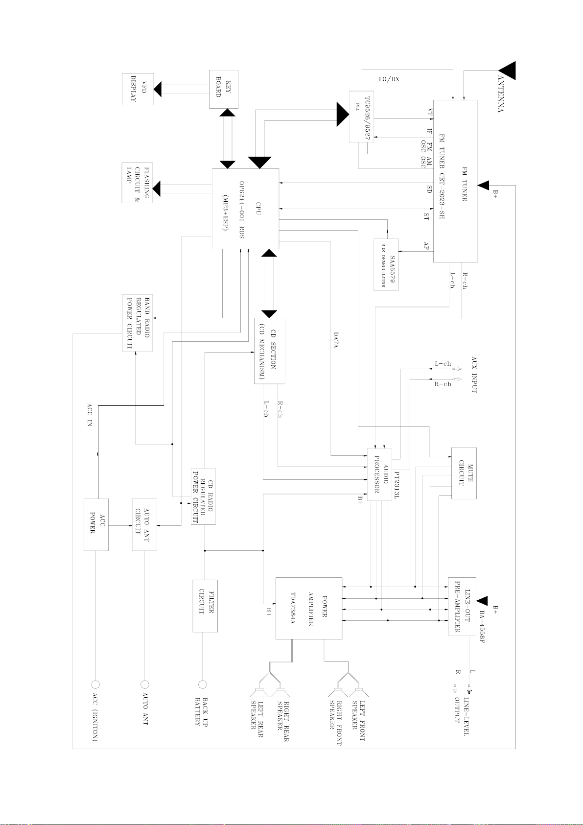
BLOCK DIAGRAM
6
Page 7

FM/MW/LW TUNER
ALIGNMENT LOCATIONS
7
Page 8

ALIGNMENT PROCEDURES
FM ADJUSTMENT
Equipment Required
z AM IF/RF signal generator
z Solid-state voltmeter (SSVM)
z Regulated DC power supply
z 2-CH voltmeter
z Distortion meter
FM Alignment Using FM Signal Generator
Note: Press the radio power switch to on the radio. Signal generator output must be kept as low as possible
to avoid overload and clipping.
Step Generator
Coupling
IF FM RF Signal
Generator to
Antenna
input.
76 kHz
Pilot
Modulation
-3 dB
Limiting
Sens.
FM SNC
Adjustment
FM Stereo
S/N
Auto Stop
Sens.
Note: The tuner module is well-adjust and adjustment is not recommended.
Signal
Generator
to antenna
receptacle
Signal
Generator
to antenna
receptacle
98.1 MHz
Dev. 45 kHz
L+R=90 %
Int. 1 kHz
60dBµV output
Signal Generator
Connected to
Antenna
Signal Generator
Connected to
Antenna.
Generator Display
10.7 MHz
Sweep
output
60 dBµV
75 kHz Dev
45% for L only
or R only pilot
level 10%
60 dBµV
Output.
98.1 MHz
@ 40 dBµ
98.1MHz
Int. 1kHz
Dev. 75kHz.
98.1 MHz
Int. 1kHz
Dev. 75kHz
28 dBµV
Adjustment Remarks
Setting
98.1 MHz T101
98.1 MHz VR105 Adjust to
98.1 MHz VR101
98.1 MHz VR106
98.1MHz VR104
98.1 MHz VR107
Adjust so that
maximum AF
output power and
minimum distortion
76 kHz
Adjust VR101
Making –14dB
(±2dB) Limiting
Sensitivity.
VOR - VOL = 10 dB
(± 3 dB)
Adjust VR104 FM
Stereo S/N is the
optimum.
Adjustment
AF to stop station.
8
Page 9
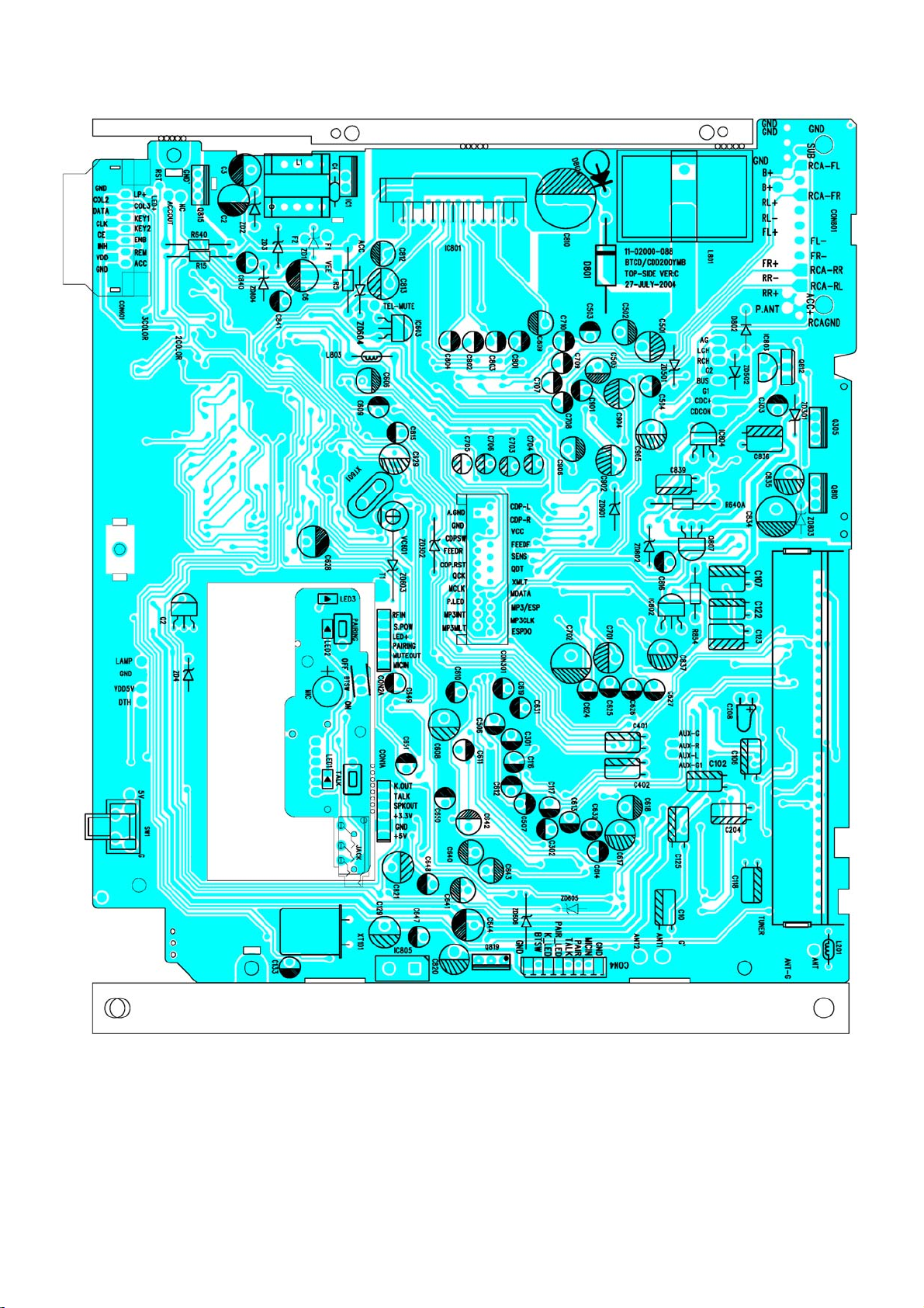
MAIN BOARD
PRINTED CIRCUIT BOARDS
TOP VIEW
9
Page 10

MAIN BOARD
BOTTOM VIEW
10
Page 11

FM TUNER BOARD
11
Page 12

KEY BOARD
TOP VIEW
12
Page 13

KEY BOARD
BOTTOM VIEW
13
Page 14

CD SERVO BOARD
TOP VIEW
14
Page 15

CD SERVO BOARD
BOTTOM VIEW
15
Page 16

BLUETOOTH PCB BOARD
TOP VIEW
16
Page 17

BLUETOOTH PCB BOARD
BOTTOM VIEW
17
Page 18

PANEL
EXPLODED VIEW
18
Page 19

EXPLODED VIEW PARTS LIST
PANEL
Ref. No. Description RS Part No. Mfr’s Part No.
Lens-B (S. OPC0000) MP3 VFD
1
Lens-S (S. OPC0000)
2
MAT Panel Top (Silver) X20.11 BT
3
Panel Top (S. OP1202)
4
Panel Bottom (F) /777
5
Open Key/F (E-Silver)
6
RE Knob Spring
7
DECARING (S. OP1202)
8
VOL Back Light
9
10
11
12
13
14
15
16
17
18
19
20
21
22
23
24
25
26
27
28
29
30
31
32
33
34
35
VOL Knob (E-Silver)
Power Key (Crystal)
SEL Key (Crystal)
EQ Key (Crystal)
Knob-3 Left
AS/PS~6 Key (L-Up) (S. OP1202)
Button Back Light
TA Key (Crystal)
PTY Key (Crystal)
AF Key (Crystal)
Knob-3 Right
BND/DSP (F) Knob (E-Silver)
7/MOD Key (L-Up) (S. OP1202)
MANU-SKIP 8-/9+ Key (L-Up) (S. OP1202)
SKIP Back Light
Key Board
ENCODER SRGP200200 (ALPS)
LCD racket Real (E)
CD100 LCD TN COLOR NEG 22X84 PIN
CD1007 B.LIGHT /WHITE
Axis Post
Right Side Block
Contact Spring
Left Side Block
E-Ring Ø1.5X4X0.4MM
Screw Ø2X8 BA/ST Black
53-G1240-31Y
53-G1239-30
61-G2101-86B
51-G2122-80
51-F2123-00
52-G2137-90E
36-11852-00
52-G2123-80
52-G2130-00
52-G2135-90E
52-G2132-01B
52-G2132-02B
52-G2132-03B
52-G2125-00
52-G2124-81
52-G2133-00
52-G2132-04B
52-G2132-05B
52-G2132-06B
52-G2129-00
52-G2138-90E
52-G2127-81
52-G2126-01
52-G2134-00
11-21730-319
18-00163-00
39-E2004-00
27-10000-01Y
02-01007-09
34-24601-00
52-E2128-00
36-78008-00
52-E2129-00
35-00001-00
40-12008-21
19
Page 20

CABINET
EXPLODED VIEW
20
Page 21

EXPLODED VIEW PARTS LIST
CABINET
Ref. No. Description RS Part No. Mfr’s Part No.
1
2
3
4
5
6
7
8
9
10
11
12
13
14
15
16
17
18
19
20
21
22
23
24
25
26
27
28
29
30
31
32
33
34
35
36
37
38
39
40
Panel
Ring (S. OPC1202)
Base
Side Bracket
CD MECH. CDM-1683EUK W/O Bracket (143A)
Heat Sink (For Wire)
Top Cabinet
Bottom Cabinet (For Wire)
Main Fiber
Main Board
Mounting Box (072)
Shade
CD Windows Sheet
Hook Shaft
Hook Spring
Hook
Push Out Spring
Panel Pole
Base Back Light (F) (White)
Front Board
20PIN Socket
Eject Key/F (L-Up) (S. OPC0000)
Eject Board
Right Bracket
Damper Gear Ass’y /19-24 T/Q
Middle Gear (F)
Left Bracket
Deck Front Bracket
Deck Rear Bracket
FM Tuner CET-2023-SH
FM Cover
IC Mounting Bracket
BLUETOOTH PCB Board
Spring Sheet
Heat Sink (7809/DB435) W/O Shaft
Wire Clip 1.0MM
Screw Ø5X18 HH
Spring Washer M5
Hexagon Nut M5
Antenna Clip 1.0MM
51-G2121-80
51-E2124-00
61-E2005-01
94-01683-11
61-E2006-00
61-B0105-01
61-B0114-01
35-B0101-00
11-02000-088
61-07211-03
81-69005-02
43-E2001-00
34-D2101-00
36-E2101-00
52-E2127-00
36-E2102-00
52-E2126-00
52-E2148-01
11-21710-348
25-F0217-20
52-G2150-01
11-21710-348
39-E2101-01
93-12246-01
52-E2130-00
39-E2102-01
39-E2105-00
39-B0101-00
29-02023-00
39-D0507-00
39-36021-00
12-00110-310
39-B0102-00
39-B0113-01
39-B1415-00
40-05018-04
35-50001-00
35-40005-00
39-B0114-00
21
Page 22

Ref. No. Description RS Part No. Mfr’s Part No.
41
42
43
44
45
46
47
48
49
50
Screw Ø2X4 BH/ST Black
Screw Ø2X6 PA/ST Black
Screw Ø2.6X4 BH/MS
Screw Ø2.6X5 BH/TAPTITE
Screw Ø2.6X6 BH/MS
Screw Ø2.6X6 PH/MS Black
Screw Ø2.6X8 BH/MS
Screw Ø2.6X10 BH/MS
Screw M2.6X20 PH/MS
Screw Ø3X5 BH/MS
40-12004-21
40-12006-20
40-02604-01
40-02605-03
40-02606-01
40-02606-20
40-02608-01
40-02610-01
40-02620-00
40-03005-01
22
Page 23

EXPLODED VIEW PARTS LIST
CMD-09
Ref. No. Description RS Part No. Mfr’s Part No.
1
2
3
4
5
6
Top W/O Brand
Bottom CMD-09
PCB Board
P-Button (S. OPC0000)
TALK-Button (S. OPC0000)
TALK Back Light
52-C0920-02W
52-C0921-01
11-02000-088
52-C0922-01
52-C0925-01
52-C0923-00
23
Page 24

EXPLODED VIEW (DECK)
24
Page 25

EXPLODED VIEW PARTS LIST (DECK)
Ref. No. Description Parts No. Q’ty
1
2
3
4
5
6
7
8
9
10
11
12
13
14
15
16
17
18
19
20
21
22
23
24
25
26
27
28
29
30
31
32
33
34
35
36
37
38
39
SENSOR
SENSOR PCB
SCREW
COVER-UPPER
LEVER DISC
GUIDE UP
BUSHING ROLLER
ROLLER DISC
SHAFT ROLLER
PIN ROLLER
PVC CAP
B/K ROLLER
PIN PULLEY
PIN IDLE
GEAR IDLE
GEAR PULLEY
BELT PULLEY
GEAR ROLLEY
LOCKER (L)
CAM (L)
S/P CAM (L)
S/P RACK
CAM (R)
LOCKER ®
GEAR RACK
GEAR LOAD ©
GEAR LOAD (D)
GEAR LOAD (B)
GEAR LOAD (A)
PIN LOAD
B/K GEAR
MOTOR
GEAR WORM
GERVO PCB ASSY
SPECIAL SCREW
S/P RO (L)
SUPPORT DAMPER
S/P RO ®
CHASSIS MAIN
ST-23G
FR
CA/H 0” TT 2*3
SECC T1.0
POM (F20-03)
POM (F20-03)
POM (F20-03)
SLICON
SUS 303
SUM24L-NI (PLATE)
PVC
SECC T1.0
SUM24L-NI (PLATE)
SUM24L-NI (PLATE)
POM (F20-03)
POM (F20-03)
CR-WRT
POM (F20-03)
POM (F20-03)
POM (F20-03)
SUS304WPB
SUS304WPB
POM (F20-03)
POM (F20-03)
POM (F20-03)
POM (F20-03)
POM (F20-03)
POM (F20-03)
POM (F20-03)
SUM24L-NI (PLATE)
SECC T1.0
FF-050SH-11190
POM (F20-03)
GLASS EPOXY 1.2T
P/H TTS 2*2
SUS304WPB
POM (F20-03)
SUS304WPB
SEEC T1.0
2
1
12
1
1
1
2
2
1
1
2
1
1
1
1
1
1
1
1
1
1
1
1
1
1
1
1
1
1
4
1
1
1
1
4
1
3
1
1
25
Page 26

EXPLODED VIEW PARTS LIST - CONTINUED (DECK)
Ref. No. Description Parts No. Q’ty
40
41
42
43
44
45
46
47
48
49
50
51
52
53
54
55
56
57
58
59
60
61
62
63
64
65
66
67
68
69
70
71
72
73
CLAMP DISC
HOLD CLAMPER
S/P CLAMPER
TURN TABLE
BASE PU
PIN SIDE (A)
SCREW
PIN SIDE (B)
DAMPER
S/P BASE
MOTOR
GEAR PU (B)
GEAR PU (A)
SCREW
MOTOR
HOUSING GEAR
SHAFT PU
SCREW
4P CONT WIRE
SPRING TENSION
GEAR PU ©
LEAD SCREW
SWITCH
SCREW
PICK UP
FPC WIRE
SPRING PU
FIBER PAPER
S/P CAM ®
TRANSIT SCREW
INSULATOR COVER
SWITCH
WASHER PE
S/P BASE ®
POM (F20-03)
SECC T1.0
SUS304WPB
ABS G/F 20%
POM (F20-03)
SUM24L-NI (PLATE)
CA/H 0” M/S 1.7*2.5
SUM24L-NI (PLATE)
BUTHYL
SUS304WPB
RF-400CA-12265
HYTRELL 5526
POM (F20-03)
CA/H 0” M/S 2*2
FF-050SH-11190
POM (F20-03)
KNN11 (PCD18)
R/H (W/W) TTB2*5
1007 #28
SUS304WPB
POM (F20-03)
BSBM
SW-110
B/H TTB1.7*8
SF-C99
POLY AMIDE
SUS T0.2
0.55
4.5*18
PE
SW-111
PE
SUS304WPB
1
1
1
1
1
2
2
2
1
2
1
1
1
6
1
1
1
1
1
1
1
1
1
1
1
1
1
1
1
2
1
1
2
2
26
Page 27

SCHEMATIC DIAGRAM (MAIN BOARD)
27
Page 28

SCHEMATIC DIAGRAM (KEY BOARD)
28
Page 29

SCHEMATIC DIAGRAM (CD SERVO BOARD)
29
Page 30

SCHEMATIC DIAGRAM (BLUETOOTH PCB BOARD)
30
Page 31

ELECTRICAL PARTS LIST
Ref. No. Part No. Description Q’ty
PC BOARD ASSY, MAIN BOARD
Q305,810
Q104,302/4,603,672~6,802/9
Q812
Q105~7,301/3,601/4/5/7~9,679/80,801/3~
6/8,811
IC802/4
Q807
ZD601/2
D802
D201,301/2,626,647,650~2,803/5/6/8/10
D801
ZD302
ZD605,802
ZD603/6
ZD604
ZD301
ZD803
IC601
IC701/2
IC602
IC603
IC801
IC805
IC803
IC101
XT601
TUNER TO GND
C7,8
C817
C135,140,603/4,805~8
C207
C108,110/1,607,630,811/8/9/22,833/8
C843
C112/3
C119,124
C101/5/9,605
C620~3
C601
C615/6
C602
01-00435-00S
01-00812-00
01-01240-00
01-03875-07
01-07805-00
01-08550-03
02-00062-07
02-04001-00
02-04148-02
02-05401-00
02-50033-00
02-50036-00A
02-50051-00
02-50056-00
02-50091-00A
02-50100-00A
03-02313-00
03-04558-06
03-06244-00
03-07035-00
03-07384-00
03-07384-11
03-07818-00
03-09257-00
04-00072-01
05-05102-00A
05-63030-00
05-63101-00
05-63102-01
05-63103-01
05-63104-01
05-63105-00
05-63153-01
05-63220-00
05-63223-01
05-63224-01
05-63270-00
05-63272-01
05-63300-00
TR. BD435 NPN TO-126 SAMSUNG
TR. 2SA812
TRANSISTOR B1240
TRANSISTOR 2SC3875G
IC-REGULATOR 78L05
TR. 8550C TO-92-B
E.S.D. DIDOE NNCD6.2G (5PIN)
DIODE IN4001
DIODE CHIP RLS4148 1206 ROHM
DIODE IN5401
ZENER DIODE 3.3V 0.5W
ZENER DIODE 3.6V 0.5W AT. ±2%
ZENER DIODE 5.1V ±5% 0.5W
ZENER DIODE 5.6V 0.5W
ZENER DIODE 9.1V ±5% 0.5W AT.
ZENER DIODE 5.1V 0.5W AT. TAPE ±2%
I. C. PT2313L
IC KIA-4558F
IC OP6244-001 RDS (MP3+ESP)
IC KIA7035P
IC TDA7384A (4X40W) “Y”
REGULATOR L7805CV (GROUND TAP)
REGULATOR LC-78L18
IC TC9257F
CRYSTAL HC-49/µS 7.2MHZ
AXIAL CER CAP 1000PF ±20% TP.
CHIP CAP 3PF ±5% NPO 0603 SMT
CHIP 100PF ±5% NPO 0603 SMT
CHIP 1000PF ±10% X7R 0603 SMT
CHIP 0.01µF ±10% X7R 0603 SMT
CHIP 0.1µF ±10% X7R 0603 SMT
CHIP 105PF/25V Y5V ±20% 0603 SMT
CHIP 0.015µF ±10% X7R 0603 SMT
CHIP CAP 22PF ±5% NPO 0603 SMT
CHIP 0.022µF ±10% X7R 0603 SMT
CHIP 0.22µF ±10% X7R 0603 SMT
CHIP CAP 27PF ±5% NPO 0603 SMT
CHIP 2700PF ±10% X7R 0603 SMT
CHIP CAP 30PF ±5% NPO 0603 SMT
2
11
1
21
2
1
2
1
14
1
1
2
2
1
1
1
1
2
1
1
1
1
1
1
1
1
2
1
8
1
11
1
2
2
4
4
1
2
1
31
Page 32

ELECTRICAL PARTS LIST - CONTINUED
Ref. No. Part No. Description Q’ty
C814
C123,606,617,629,837
C834
C702
C106,640~3,809,812
C107,701
C618,816
C810
C102,125,303,608,644/8,813,820/1,835
C650
C651
C116/7,122,610,801~4
C612/3
C611/4/9,631/2
C815
C609
C624~7,703~6
R854
R19
R103,134/5,140,620,701,857
R118,603
R101,120,309,605/54/76,716~9,827/52
R102/9,119,306,321/2,610/2/3/5,631/2,64
4/7/8,653/5/6,801~4,820,837/9,845/8,851
/3/9,863
R819,822,840,860
R612/3/6/9
R651
R818
R649,650
R830
R645/6
R323,850
R121,609,615,633/4
R662~4,675/8/9,702/3,805~8,813,829,855
/8
R614,626,661,680
R704/9,710/5
R108,671
R113/4,629/30,657/8
R861
05-63474-02
06-10107-02
06-10227-01
06-10227-02
06-16106-02E
06-16107-04
06-16226-02
06-16338-00S
06-16476-03
06-50104-01L
06-50105-01
06-50105-03
06-50224-02
06-50225-02
06-50335-01
06-50474-02E
06-50475-03
07-05100-00
07-63000-00
07-63100-00
07-63101-00
07-63102-00
07-63103-00
07-63104-00
07-63105-00
07-63124-00
07-63152-00
07-63155-00
07-63182-00
07-63220-00
07-63221-00
07-63222-00
07-63223-00
07-63224-00
07-63273-00
07-63331-00
07-63332-00
07-63333-00
CHIP CAP 0.47µF ±20% X7R 0603 SMT
E. CAP 100µF 10V (6X5) SPUER MINI
E. CAP 220µF 10V (Ø6MM MINI)
E. CAP 220µF 10V (Ø8X5MM)
E. CAP 10µF/16V (4X5MM RC3)
E. CAP 100µF 16V (Ø6X5MM)
E. CAP 22µF 16V (Ø5X5MM)
E. CAP 3300µF 16V 105°C
E. CAP 47µF 16V (6X5)
E. CAP 0.1µF 50V Ø4X5MM LELON
E. CAP 1µF 50V (Ø4X7MM)
E. CAP 1µF 50V (Ø4X5MM)
E. CAP 0.22µF 50V (Ø3X5MM)
E. CAP 2.2µF 50V (4X5)
E. CAP 3.3µF 50V (Ø4X7 MM)
E. CAP 0.47µF/50V (4X5MM RC03)
E. CAP 4.7µF 50V (4X7MM)
RES. 10Ω 1/4W
CHIP RES. 0Ω ±5% 0603 SMT
CHIP RES. 10Ω ±5% 0603 SMT
CHIP RES. 100Ω ±5% 0603 SMT
CHIP RES. 1kΩ ±5% 0603 SMT
CHIP RES. 10kΩ ±5% 0603 SMT
CHIP RES. 100kΩ ±5% 0603 SMT
CHIP RES. 1MΩ ±5% 0603 SMT
CHIP RES. 120kΩ ±5% 0603 SMT
CHIP RES. 1.5kΩ ±5% 0603 SMT
CHIP RES. 1.5MΩ ±5% 0603 SMT
CHIP RES. 1.8kΩ ±5% 0603 SMT
CHIP RES. 22Ω ±5% 0603 SMT
CHIP RES. 220Ω ±5% 0603 SMT
CHIP RES. 2.2kΩ ±5% 0603 SMT
CHIP RES. 22kΩ ±5% 0603 SMT
CHIP RES. 220kΩ ±5% 0603 SMT
CHIP RES. 27kΩ ±5% 0603 SMT
CHIP RES. 330Ω ±5% 0603 SMT
CHIP RES. 3.3kΩ ±5% 0603 SMT
CHIP RES. 33kΩ ±5% 0603 SMT
1
5
1
1
7
2
2
1
10
1
1
8
2
5
1
1
8
1
1
7
2
12
34
4
1
4
1
2
1
2
2
5
14
4
4
2
6
1
32
Page 33

ELECTRICAL PARTS LIST - CONTINUED
Ref. No. Part No. Description Q’ty
R308,607
R643
R324
R627/8
R136
R122/9/30,602/4/6,611
R124~6,305/7,320,608,659,667/8,674/7,7
06/7,712/3,823,847/6/9,856
R814~7
R622
R809~12
R624
R705/8,711/4
R621
L803
MB
L801
PC BOARD ASSY, FM TUNER BOARD
Q104/6
Q101~3,204
D107
D101
D106
IC101
IC102
C136
C115/6
C122
C117
C126
C123
C121
C135,001/2
C109,129,133
C108/9,111/2/8
C130
C114
C134
C102
07-63334-00
07-63391-00
07-63392-00
07-63394-00
07-63471-00
07-63472-00
07-63473-00
07-63474-00
07-63512-00
07-63561-00
07-63752-00
07-63822-00
07-63823-00
09-70100-01
11-02000-088
15-27012-11J
01-02785-00C
01-03875-07
02-04148-00
02-04148-00A
02-04148-02
03-01140-00
03-03375-00
05-03102-10
05-03223-10
05-05103-10H
05-05330-00H
05-05333-00
05-09102-11
05-63102-01
05-63103-01
05-63104-01
05-63223-01
05-63332-01
06-10107-01
06-10227-01
06-16106-01
CHIP RES. 33kΩ
CHIP RES. 390Ω ±5% 0603 SMT
CHIP RES. 3.9kΩ ±5% 0603 SMT
CHIP RES. 390kΩ ±5% 0603 SMT
CHIP RES. 470Ω ±5% 0603 SMT
CHIP RES. 4.7kΩ ±5% 0603 SMT
CHIP RES. 47kΩ ±5% 0603 SMT
CHIP RES. 470kΩ ±5% 0603 SMT
CHIP RES. 5.1kΩ
CHIP RES. 560Ω ±5% 0603 SMT
CHIP RES. 7.5kΩ ±5% 0603 SMT
CHIP RES. 8.2kΩ ±5% 0603 SMT
CHIP RES. 82kΩ ±5% 0603 SMT
MICRO INDUCTOR 10UH AXIAL TYPE
BT-CDD200X3. (14/5,17~22) YMB D/S
1.6X152X182
RING COIL Ø27X12MM V-TYPE
TRANSISTOR 2SC2785 “NEC”
TRANSISTOR 2SC3875G
DIODE IN-4148
DIODE IM-4148 AT. (TAPPING)
DIODE CHIP PLS4148 1206 ROHM
I.C. LA-1140
I.C. LA-3375
CHIP CER CAP 1000P 50V K Y5P TA
CHIP CAP CM21X7R223K25AT
AXIAL CER UP050B103K-B-B7 ±10%
AXIAL UP050SL 330J-B-B (±5%)
AXIAL CER CAP 0.33µF +80/-20%
POLY CAP 1000PF ±5%
CHIP 1000PF ±10% X7R 0603 SMT
CHIP 0.01µF ±10% X7R 0603 SMT
CHIP 0.1µF ±10% X7R 0603 SMT
CHIP 0.022µF ±10% X7R 0603 SMT
CHIP 3300PF ±10% X7R 0603 SMT
E. CAP 100µF 10V (Ø5X7MM MINI)
E. CAP 220µF 10V (Ø6MM MINI)
E. CAP 10µF 16V (Ø4X7MM)
2
1
1
2
1
7
25
4
1
4
1
4
1
1
1
1
2
4
1
1
1
1
1
1
2
1
1
1
1
1
3
3
5
1
1
1
1
33
Page 34

Ref. No. Part No. Description Q’ty
C113,128,132
C110,125/7,131
C124
J01~5
R114
V104
VR106
R119
R116/8
R136
J5~15,R152
R128,J16
R109,133,108,129,003
R002,103,112/7,149
R120
R113,132
R001
R150
R115
R107,110,134
R106,135
R111
R127
T101
CF101/2
VR103
VR107
VR105
VR101
ELECTRICAL PARTS LIST - CONTINUED
06-16475-01
06-50105-01
06-50335-02C
07-05000-54
07-05123-16
07-05203-16
07-05392-16
07-05472-16
07-05473-16
07-05824-54
07-63000-00
07-63100-00
07-63102-00
07-63103-00
07-63104-00
07-63153-00
07-63182-00
07-63222-00
07-63223-00
07-63331-00
07-63392-00
07-63473-00
07-63683-00
07-63752-00
08-70174-01
09-10710-01
12-01140-135
17-30103-06S
17-30104-06S
17-30502-06S
17-30503-06S
PC BOARD ASSY, KEY BOARD
E. CAP 4.7µF 16V (Ø4X7MM)
E. CAP 1µF 50V (Ø4X7MM)
E. CAP 3.3µF 50V (Ø3X5MM)
CHIP RES. 0Ω 1/10W
RES. 12kΩ 1/16W
RES. 20kΩ 1/16W ±5%
RES. 3.9kΩ 1/16W
RES. 4.7kΩ 1/16W
RES. 47kΩ 1/16W
CHIP RES. 820kΩ 1/10W
CHIP RES. 0Ω 0603 SMT
CHIP RES. 10Ω ±5% 0603 SMT
CHIP RES. 1kΩ ±5% 0603 SMT
CHIP RES. 10kΩ ±5% 0603 SMT
CHIP RES. 100kΩ ±5% 0603 SMT
CHIP RES. 15kΩ ±5% 0603 SMT
CHIP RES. 1.8kΩ ±5% 0603 SMT
CHIP RES. 2.2kΩ ±5% 0603 SMT
CHIP RES. 22kΩ ±5% 0603 SMT
CHIP RES. 330Ω ±5% 0603 SMT
CHIP RES. 3.9kΩ ±5% 0603 SMT
CHIP RES. 47kΩ ±5% 0603 SMT
CHIP RES. 68kΩ ±5% 0603 SMT
CHIP RES. 7.5kΩ ±5% 0603 SMT
TFT 10.7MHZ H=7.5MM
FILTER SEF 10.7MJ ‘MURATA’ ±30K
LA1140 TUNER BOARD 74X40X1.2
SEMI-FIXED EVND2AA03B14 (10KB)
SEMI-FIXED EVND2AA03B15 3V
SEMI-FIXED EVND2AA03B53
SEMI-FIXED EVND2AA03B54 (50KΩ)
3
4
1
5
1
1
1
1
2
1
12
2
5
5
1
2
1
1
1
3
2
1
1
1
1
2
1
1
1
1
1
LED1~24
IC601
C602/1~9,613~8
C601
C1
R644~50
R621
R612
02-01112-06M
03-16311-01
05-63101-00
05-63104-01
05-63221-00
07-63101-00
07-63102-00
07-63103-00
34
SMD LED S172DNB4-5 0805 BLUE
IC PT6311 VFD CONTROLLER
CHIP 100PF ±5% NPO 0603 SMT
CHIP 0.1µF ±10% X7R 0603 SMT
CHIP 220PF ±5% NPO 0603 SMT
CHIP RES 100Ω ±5% 0603 SMT
CHIP RES 1kΩ ±5% 0603 SMT
CHIP RES 10kΩ ±5% 0603 SMT
24
1
10
1
2
8
1
1
Page 35

ELECTRICAL PARTS LIST - CONTINUED
Ref. No. Part No. Description Q’ty
R608 (PTY)
R622
R609
R604,616
R624
R605,615/7
R623
R611
R606,618
R625
R619,607 (TA)
R614
R601
R603
R620
R613
KB
BAND,DSP,RES
VOL1
07-63122-00
07-63152-00
07-63153-00
07-63181-00
07-63182-00
07-63221-00
07-63222-00
07-63272-00
07-63331-00
07-63393-00
07-63471-00
07-63473-00
07-63562-00
07-63563-00
07-63681-00
07-63823-00
11-21730-319
16-01107-00K
16-01140-04
18-00163-00
25-M0217-20
27-B0883-00
PC BOARD ASSY, SDK/CD SERVO BOARD
CHIP RES 1.2kΩ ±5% 0603 SMT
CHIP RES 1.5kΩ ±5% 0603 SMT
CHIP RES 15kΩ ±5% 0603 SMT
CHIP RES 180Ω ±5% 0603 SMT
CHIP RES 1.8kΩ ±5% 0603 SMT
CHIP RES 220Ω ±5% 0603 SMT
CHIP RES 2.2kΩ ±5% 0603 SMT
CHIP RES 2.7kΩ ±5% 0603 SMT
CHIP RES 330Ω ±5% 0603 SMT
CHIP RES 39kΩ ±5% 0603 SMT
CHIP RES 470Ω ±5% 0603 SMT
CHIP RES 47kΩ ±5% 0603 SMT
CHIP RES 5.6kΩ ±5% 0603 SMT
CHIP RES 56kΩ ±5% 0603 SMT
CHIP RES 680Ω ±5% 0603 SMT
CHIP RES 82kΩ ±5% 0603 SMT
CD-F2173 VFD KB D/S 1.2X42X182.6MM
TACT SW. DCT/1101 4.3MM 2 PIN
TACT SW. KPS-1107SW H=2.5 KIE SMD
ENCODER SRGP200200 (ALPS)
20PIN PLUG
VFD BJ883GNK (FUTABA) CDX3.2
1
1
1
2
1
3
1
1
2
1
2
1
1
1
1
1
1
3
16
1
1
1
Q2~6,8
Q1,302/4
Q7
Q301/3
D1,2
D5,6
D611,635
ZD302
D4
D3
D7
U1
U5
U3
U2
U4
01-00103-00
01-00812-00
01-01225-13
01-03875-07
02-00144-00
02-04148-02
02-04148-00A
02-50033-00A
02-50036-00
02-50051-00
02-50151-00
03-09226-00
03-09259-00
03-09276-00
03-09291-00
03-M0404-04
TR. KRC103S
TR. 2SA812
TRANSISTOR 2SD1225M
TRANSISTOR 2SC3875G
IR LED MIE 144A1MC
DIODE CHIP RLS4148 1206 ROHM
DIODE IN-4148 AT. (TAPPING)
ZENER DIODE 3.3V 0.5W AT.
ZENER DIODE 3.6V 0.5W
ZENER DIODE 5.1V 0.5W
5.1V ZENER DIODE (SMD1206)
IC SIL 9226
IC KA9259D
IC S5L 9276X01-EORN
IC S5L9291X01-EORO
IC 4X4 DRAM SI17400B (FUJITSU DICE)
6
3
1
1
2
2
2
1
1
1
1
1
1
1
1
1
35
Page 36

ELECTRICAL PARTS LIST - CONTINUED
Ref. No. Part No. Description Q’ty
X301
C10,126,223/4,235/7/9
C129
C127,214
C102,113/6/7,130,140/1,219,229
C100/3/6/8,119,122/4/5,131/2/4/6~8,211~
3/5/7,222/7/8,231/4/6/8,240~9,253,300/2
~6/8
C225/6
C139
C104
C107,123
C307
C220/1
C121
C105,111
C128
C120,232/3
C115
C216
C303,832
C101,202/9,218,301/9~11
C135,142
C301/2
R301
R305
R102,120,204~7,213/6,244,251/2/6/8,303
R236,255,264,304
R105
R210,222/3
R129/30,136/7,217/8,306,321/2
R122/3,224/5
R202,235
R125/6,134,201,221,243
R231
R131
R302,314,323
R303/4/9
R100/1,124,135
04-00169-00
05-16106-10
05-63020-00
05-63102-01
05-63103-01
05-63104-01
05-63152-01
05-63153-01
05-63220-00
05-63222-01
05-63223-01
05-63330-00
05-63333-01
05-63391-00
05-63472-01
05-63474-00
05-63683-01
05-63821-00
06-10107-02
06-16107-54
06-16476-54
06-50225-02
07-05047-00
07-05103-16A
07-63000-00
07-63015-00
07-63100-00
07-63102-00
07-63103-00
07-63104-00
07-63105-00
07-63153-00
07-63181-00
07-63203-00
07-63221-00
07-63222-00
07-63224-00
CRYSTAL HC-49/US 16.934MHZ
TAN CAP 10UF 16V ±10% (4.5X7)
CHIP CAP 2PF ±5% NPO 0603 SMT
CHIP 1000PF ±10% X7R 0603 SMT
CHIP 0.01µF ±10% X7R 0603 SMT
CHIP 0.1µF ±10% X7R 0603 SMT
CHIP 1500PF ±10% X7R 0603 SMT
CHIP 0.015µF ±10% X7R 0603 SMT
CHIP CAP 22PF ±5% NPO 0603 SMT
CHIP 2200PF ±10% X7R 0603 SMT
CHIP 0.022µF ±10% X7R 0603 SMT
CHIP CAP 33PF ±5% NPO 0603 SMT
CHIP 0.033µF ±10% 0603 SMT
CHIP 390PF ±5% NPO 0603 SMT
CHIP 4700PF ±10% X7R 0603 SMT
CHIP CAP 0.47µF ±5% (+80/-20%)
CHIP 0.068µF ±10% 0603 SMT
CHIP 820PF ±5% 0603 SMT
E. CAP 100µF 10V (6X5) SUPER MINI
E. CAP CHIP 100µF 16V Ø6.3X5.5
E. CAP CHIP 47µF 16V Ø5X5.5
E. CAP 2.2µF 50V (4X5)
RES. 4.7Ω 1/4W
RES. 10kΩ 1/16W (TAPPING)
CHIP RES 0Ω 0603 SMT
CHIP RES 1.5Ω 0603 SMT
CHIP RES 10Ω ±5% 0603 SMT
CHIP RES 1kΩ ±5% 0603 SMT
CHIP RES 10kΩ ±5% 0603 SMT
CHIP RES 100kΩ ±5% 0603 SMT
CHIP RES 1MΩ ±5% 0603 SMT
CHIP RES 15kΩ ±5% 0603 SMT
CHIP RES 180Ω ±5% 0603 SMT
CHIP RES 20kΩ ±5% 0603 SMT
CHIP RES 220Ω ±5% 0603 SMT
CHIP RES 2.2kΩ ±5% 0603 SMT
CHIP RES. 220kΩ ±5% 0603 SMT
1
7
1
2
9
44
2
1
1
2
1
2
1
2
1
3
1
1
2
8
2
2
1
1
14
4
1
3
9
4
2
6
1
1
3
3
4
36
Page 37

ELECTRICAL PARTS LIST - CONTINUED
Ref. No. Part No. Description Q’ty
R246
R128
R220
R260,308
R301/2,324
R211/2
R263,300
R132,226~30,245~50/3/4/9,261,310~3/5~
9
R103/4/8,127,307,320
R107
R133,209,237~42
R214/9
R109
SW101
PC BOARD ASSY, LINE OUT BOARD
07-63272-00
07-63274-00
07-63333-00
07-63334-00
07-63392-00
07-63393-00
07-63471-00
07-63472-00
07-63473-00
07-63683-00
07-63822-00
07-63823-00
07-63913-00
12-14311-120
16-00033-01
CHIP RES. 2.7kΩ ±5% 0603 SMT
CHIP RES. 270kΩ ±5% 0603 SMT
CHIP RES 33kΩ ±5% 0603 SMT
CHIP RES. 330kΩ
CHIP RES 3.9kΩ ±5% 0603 SMT
CHIP RES 39kΩ ±5% 0603 SMT
CHIP RES 470Ω ±5% 0603 SMT
CHIP RES 4.7kΩ ±5% 0603 SMT
CHIP RES. 47kΩ ±5% 0603 SMT
CHIP RES. 68kΩ ±5% 0603 SMT
CHIP RES. 8.2kΩ ±5% 0603 SMT
CHIP RES 82kΩ ±5% 0603 SMT
CHIP RES. 91kΩ ±5% 0603 SMT
PCB CDX3.20.11.4 SERVO D/S
MICRO SWITCH MPU10371MLBO (MIC)
1
1
1
2
3
2
2
24
6
1
8
2
1
1
1
C707/8
R721/2
RCA
Q1
R2
R
R7
R1
R3
R6
R4,5
EJ
06-50105-03
07-63102-00
20-20360-08
PC BOARD ASSY, FRONT BOARD
01-08050-03
02-0112-06M
02-30000-12
02-30703-40J
07-05221-00
07-63000-00
07-63103-00
07-63104-00
07-63393-00
07-63472-00
07-63821-00
11-21710-348
16-01140-04A
16-51377-00A
25-00100-06
25-00100-07
25-00100-08
25-32145-02
25-F0217-20
E. CAP 1µF 50V (Ø4X5MM)
CHIP RES 1kΩ ±5% 0603 SMT
RCA CABLE WIRE 360MM GREY
TR. 8050C TO-92-B
SMD LED S172DNB4-5 0805 BLUE
LED Ø3MM RED (WIDE ANGLE)
PLAMP 3V 40MM 3X7 K.T.
RES 220Ω 1/4W
CHIP RES 0Ω ±5% 0603 SMT
CHIP RES 10kΩ ±5% 0603 SMT
CHIP RES 100kΩ ±5% 0603 SMT
CHIP RES 39kΩ ±5% 0603 SMT
CHIP RES 4.7kΩ ±5% 0603 SMT
CHIP RES 820Ω ±5% 0603 SMT
CD-F2171 F/EJB PCB 1.2X81.4X31.45
TACT SW KPS-1107SW TAPPING
PUSH SW SPPB51 “ALPS”
RAINBOW WIRE #30 6PIN 100MM
RAINBOW WIRE #30 7PIN 100MM
RAINBOW WIRE #30 8PIN 100MM
RAINBOW WIRE #32 145PIN 2PIN
20PIN SOCKET
2
2
1
1
1
1
1
1
1
1
1
1
1
2
1
1
1
1
1
1
1
1
37
Page 38

ELECTRICAL PARTS LIST - CONTINUED
Ref. No. Part No. Description Q’ty
PC BOARD ASSY, BLUETOOTH PCB BOARD
Q678
Q377
Q1
LED1,2
LED3
Q2
U5
U1
U4
U2
U3
X1
C23,34,40/1
C5,7,11/2,21/4,42/3
C38
C1,2,6,10/6/8,22/5/6/8,33,44
C36/9
C3,4
C8,13
C652
C9,14,20
C35/7
R18,20/7
R2,11
R3,6,7,24/6
R8,9,10/5/6/9,31
R33
R29
R30
R12,32,673
R672
R28
R4
R23/5
R22
R1,21
R5,13/4
01-00812-00
01-03875-07
01-03875-07K
02-01112-00F
02-01112-02F
03-00810-01
03-01117-00
03-08111-01
03-11117-00
03-16355-00
03-45483-00
04-04096-00
05-16105-00
05-16106-10
05-63103-01
05-63104-01
05-63105-00
05-63220-00
05-63221-00
05-63223-01
05-63330-00
05-63471-00
07-63000-00
07-63100-00
07-63102-00
07-63103-00
07-63104-00
07-63121-00
07-63221-00
07-63223-00
07-63224-00
07-63271-00
07-63274-00
07-63332-00
07-63333-00
07-63473-00
07-63512-00
12-00110-310
TR. 2SA812
TRANSISTOR 2SC3875G
TR. 2SC3875G NPN SOT-23 KEC
SMD LED PG1112H GREEN “STANLEY”
SMD LED PG1112H RED “STANLEY”
BHF RESET IC ASM810SUR-T 3-SOT23
VOLTAQE REGULATOR LD1117S
BTR110A-BHF111 (MODULE)
VOLTAGE GEGULATOR AT1117E33A
D16355 PQFP (HANDSFREE DSP)
MC145483SD SSOP (CODEC)
CRYSTAL 4.096MHZ HC-49/US
TAN. CAP 1µF 16V ±10%
TAN. CAP 10µF 16V ±10% 1206 SMD
CHIP 0.01µF ±10% X7R 0603 SMT
CHIP 0.1µF ±10% X7R 0603 SMT
CHIP 105PF/25V Y5V ±20% 0603 SMT
CHIP CAP 22PF ±5% NPO 0603 SMT
CHIP 220PF ±5% NPO 0603 SMT
CHIP 0.022µF ±10% X7R 0603 SMT
CHIP CAP 33PF ±5% NPO 0603 SMT
CHIP 470PF ±5% NPO 0603 SMT
CHIP RES 0Ω ±5% 0603 SMT
CHIP RES 10Ω ±5% 0603 SMT
CHIP RES 1kΩ ±5% 0603 SMT
CHIP RES 10kΩ ±5% 0603 SMT
CHIP RES 100kΩ ±5% 0603 SMT
CHIP RES 120Ω ±5% 0603 SMT
CHIP RES 220Ω ±5% 0603 SMT
CHIP RES 22kΩ ±5% 0603 SMT
CHIP RES 220kΩ ±5% 0603 SMT
CHIP RES 270Ω ±5% 0603 SMT
CHIP RES 270kΩ ±5% 0603 SMT
CHIP RES 3.3kΩ ±5% 0603 SMT
CHIP RES 33kΩ ±5% 0603 SMT
CHIP RES 47kΩ ±5% 0603 SMT
CHIP RES 5.1kΩ
BLUETOOTH PCB D/S 55X32X0.8MM
1
1
1
2
1
1
1
1
1
1
1
1
4
8
1
12
2
2
2
1
3
2
3
2
5
7
1
1
1
3
1
1
1
2
1
2
3
1
38
Page 39

ELECTRICAL PARTS LIST - CONTINUED
Ref. No. Part No. Description Q’ty
MTC
CON1,2
IC1
Q1
D1/3,631
D2
ZD1,2
ZD3
C4
C1
C5
C3
C6
C2
R5
R16/7
R11
R6
R10
R2
R1
R8
R3
L1
14-08111-00
16-00035-04
16-01007-00K
25-19101-06
PC BOARD ASSY, JB. EL DRIVER SECTION
01-00435-00S
01-03875-07
02-04148-00A
02-04148-02
02-50068-00A
02-50100-00A
05-05474-00H
05-63104-01
05-63182-00
06-16227-01
06-16476-03
06-50336-00
07-05022-10
07-63000-00
07-63152-00
07-63223-00
07-63242-00
07-63333-00
07-63471-00
07-63561-00
07-63682-00
15-00013-00
BLUETOOTH MIC -66±2DB (CM6052/T)
Ø3.5MM JACK (4PIN) W/SW
TACT SW. DCT/1101 4.3MM 2 PIN
6P SOCKET DIP 2.0MM (CWB)
TR. BD435 NPN TO-126 SAMSUNG
TRANSISTOR 2SC3875G
DIODE IN-4148 AT. (TAPPING)
DIO CHIP RLS4148 1206 ROHM
ZENER DIODE 6.8V 0.5W AT.
ZENER DIODE 10V 0.5W AT. TAPE
AXIAL UP050F474Z-B-BZ +80/-20%
CHIP 0.1µF ±10% X7R 0603 SMT
CHIP CAP 1800PF (±10%) NPO 0603 SMT
E. CAP 220µF 16V (Ø6.3X12MM)
E. CAP 47µF 16V (6X5)
E. CAP 33µF 50V
RES 2.2Ω 1/2W
CHIP RES 0Ω 0603 SMT
CHIP RES 1.5kΩ ±5% 0603 SMT
CHIP RES 22kΩ ±5% 0603 SMT
CHIP RES 2.4kΩ ±5% 0603 SMT
CHIP RES 33kΩ ±5% 0603 SMT
CHIP RES 470Ω ±5% 0603 SMT
CHIP RES 560Ω ±5% 0603 SMT
CHIP RES 6.8kΩ ±5% 0603 SMT
VFD TRANS EE-13 SAGAMI
1
1
2
2
1
1
3
1
2
1
1
1
1
1
1
1
1
2
1
1
1
1
1
1
1
1
39
Page 40

SPECIFICATIONS
T. H. D........................................................................................................................................... Less than 0.35%
Signal to Noise Radio ................................................................................................................... More than 55 dB
Channel Separation...................................................................................................................... More than 45 dB
Frequency Response ........................................................................................................................ 40Hz - 18kHz
Stereo Separating (FM) .................................................................................................................. 30 dB (at 1kHz)
Signal to Noise Ratio (FM) .......................................................................................................... Better than 60 dB
Output Power............................................................................................................................................. 4 X 40W
Speaker Output Impedance................................................................................................................... 4 To 8 ohm
Power Source ................................................................................................................DC 12V, Negative ground.
Frequency Range ................................................................................................................. FM 87.5 – 107.9 MHz
.................................................................................................................................................. AM 530 - 1710 kHz
Sensitivity............................................................................................................................... FM 4 µV (S/N=30dB)
.......................................................................................................................................... AM 36 dBµ (S/N=20 dB)
Specifications are subject to change without notice.
40
 Loading...