

Page 1

R
EJECT
PTY
LOU
BND
ENTER
TUNE/TRACK
CAR CD/MP3 PLAYER
RDS
PLL SYNTHESIZER STEREO RADIO WITH
COMPACT DISC PLAYER DIGITAL
OPEN
7
MODE
AUDIO
ADJUST
SEL
P-EQ
DSP
VFD
1
PAU
2
SCN
3
RPT
4
SHF
5 6
AMS
MP3
9
TA
AF
8
PWR
ILL
MODEL: CD801MP/FM
Page 2

CONTENTS
Page
Disassembly Instructions ·······················································································································3
Disassembly Diagram ····························································································································4
Operation check ··································································································································5
Block Diagram ·····································································································································6
Alignment Locations······························································································································7
Alignment Procedures ····························································································································8
Printed Circuit Boards····························································································································9
Wiring Diagram ···································································································································16
Exploded Views (Panel)·······················································································································17
Exploded View Parts Lists (Panel)········································································································18
Exploded Views (Cabinet)····················································································································19
Exploded View Parts Lists (Cabinet)·····································································································20
Exploded Views (Deck)························································································································22
Exploded View Parts Lists (Deck)·········································································································23
Schematic Diagram·····························································································································25
Electrical Parts List·····························································································································27
Specifications ·····································································································································34
2
Page 3

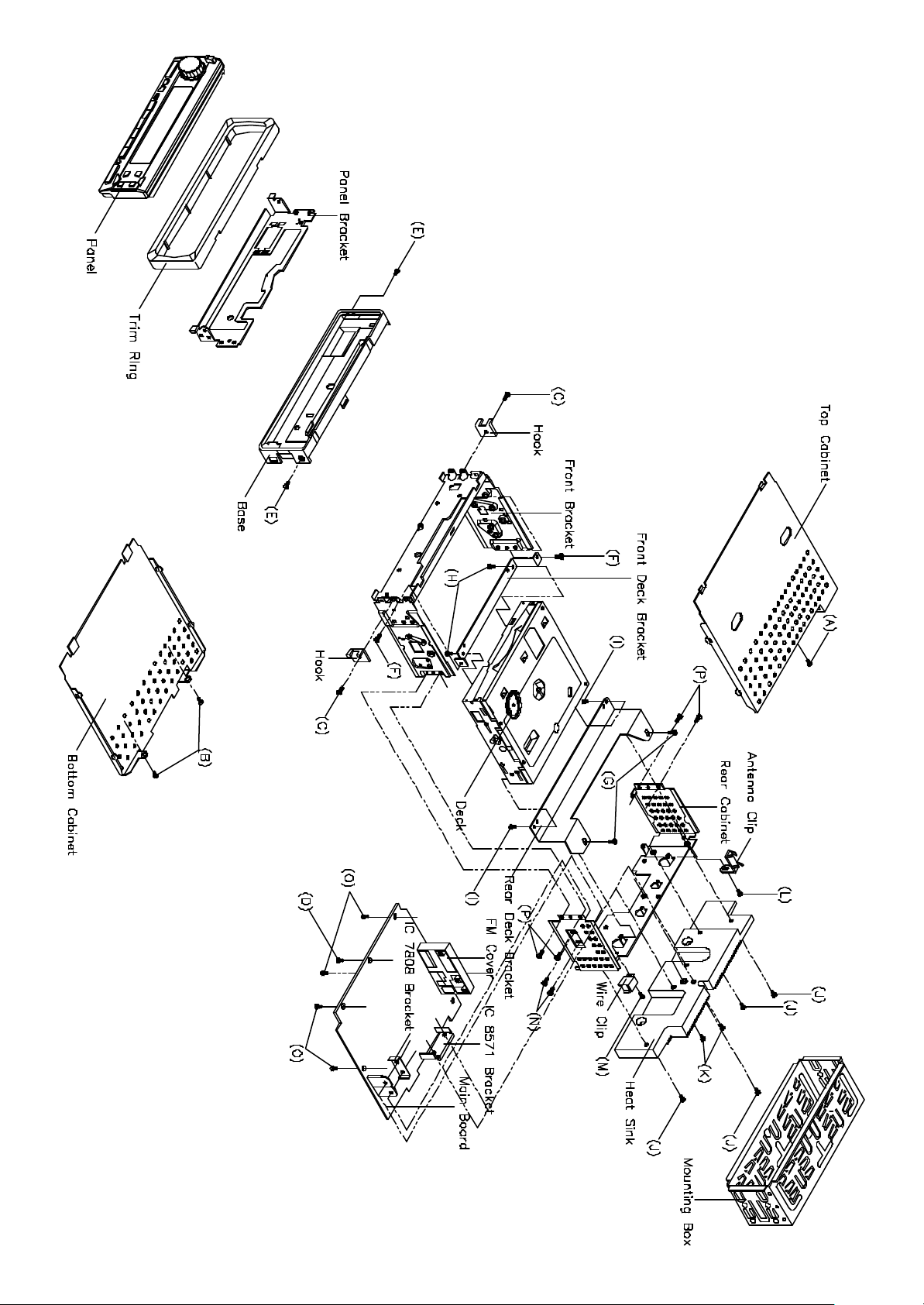
DISASSEMBLY INSTRUCTIONS
1. Using the unlock key that came with the unit or a similar tool, unlock the Mounting Box and remove
toward the rear of the unit.
2. Remove the screw (A) located on the rear of the top cabinet and remove the Top Cabinet.
3. Remove two screws (B) located on the rear of the bottom cabinet then remove the Bottom Cabinet.
4. Remove two screws (C) (one located at the left side and one located at the right side of the Front Bracket)
then remove the Hooks.
5. Remove the Front Panel and the Ring.
6. Remove two screws (D) from each side of the base then remove the Base.
7. Remove two screws (E) from the front bracket and remove two screws (F) from the rear cabinet.
8. Remove two screws (G) from the front deck bracket then remove the Front Deck Bracket.
Remove two screws (H) from the rear deck bracket then remove the Deck and the Rear Deck Bracket.
9. Remove the screw (I) and three screws (J) from the Heat Sink then remove the Heat Sink and the K7377 Heat
Sink.
10. Remove the screws (K) and remove the Antenna Clip.
Remove the screw (L) and remove the Wire Clip.
11. Remove two screws (M) from the rear cabinet of the right side then remove the IC7805 Bracket.
12. Remove five screws (N) from the main board then remove the Main Board.
13. Remove four screws (O) from each side of the rear cabinet then remove the Front Bracket and the Rear
Cabinet.
3
Page 4

DISASSEMBLY DIAGRAM
4
Page 5
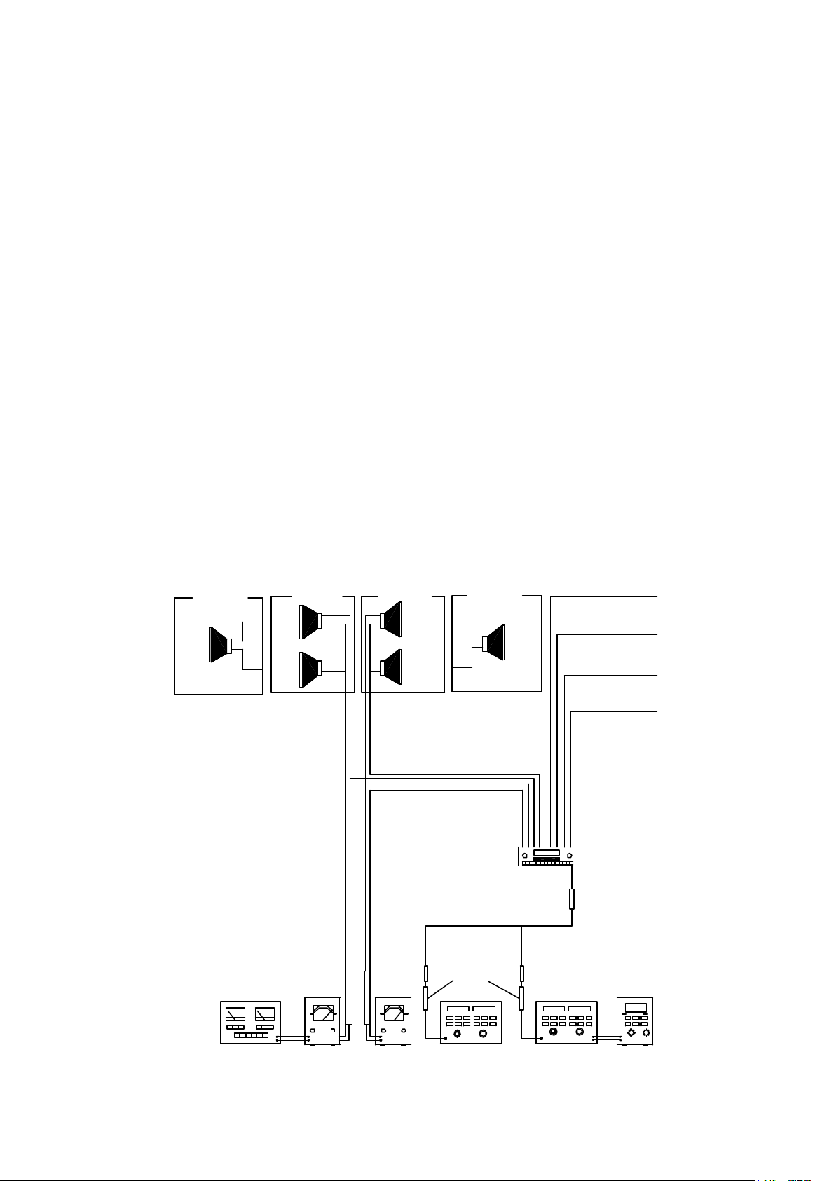
OPERATION CHECK
GENERAL SPECIFICATIONS OF SIGNAL
Standard frequency
Signal output
Modulation
FM
MW
LW
FM
MW
LW
MW
FM Stereo
98.1 MHz (87.5, 108.0 MHz)
1000 kHz (522, 1620 kHz)
200 kHz (144, 288 kHz)
1mV
5 mV
5 mV
400 Hz 30% MOD.
1 kHz 75kHz DEV.
46% for L only or
R only pilot level 8%
AF output level FM/MW/LW
Power source voltage DC 14.0V (Backup voltage is the same as this)
AF load impedance 4 ohm pure resistance
Balance Center position of level
Tone Center position
The signal strength read in this section is voltage on the antenna.
Test Diagram
2-SPEAKER
FRONT
SPK.
4-SPEAKER 4-SPEAKER
RL.
SPR.
FL.
SPK.
RR.
SPK.
FR.
SPE.
2-SPEAKER
FRONT
SPK.
ACC (DV14.4V)
BACK UP (14.4V)
GROUND
DISTORTION
METER
VTVM
VTVM
5
DUMMY
ANTANNA
AM SG
MAIN UNIT
FM SG
POWER ANTANNA
ANT
MPX
STEREOS
MODULATOR
Page 6
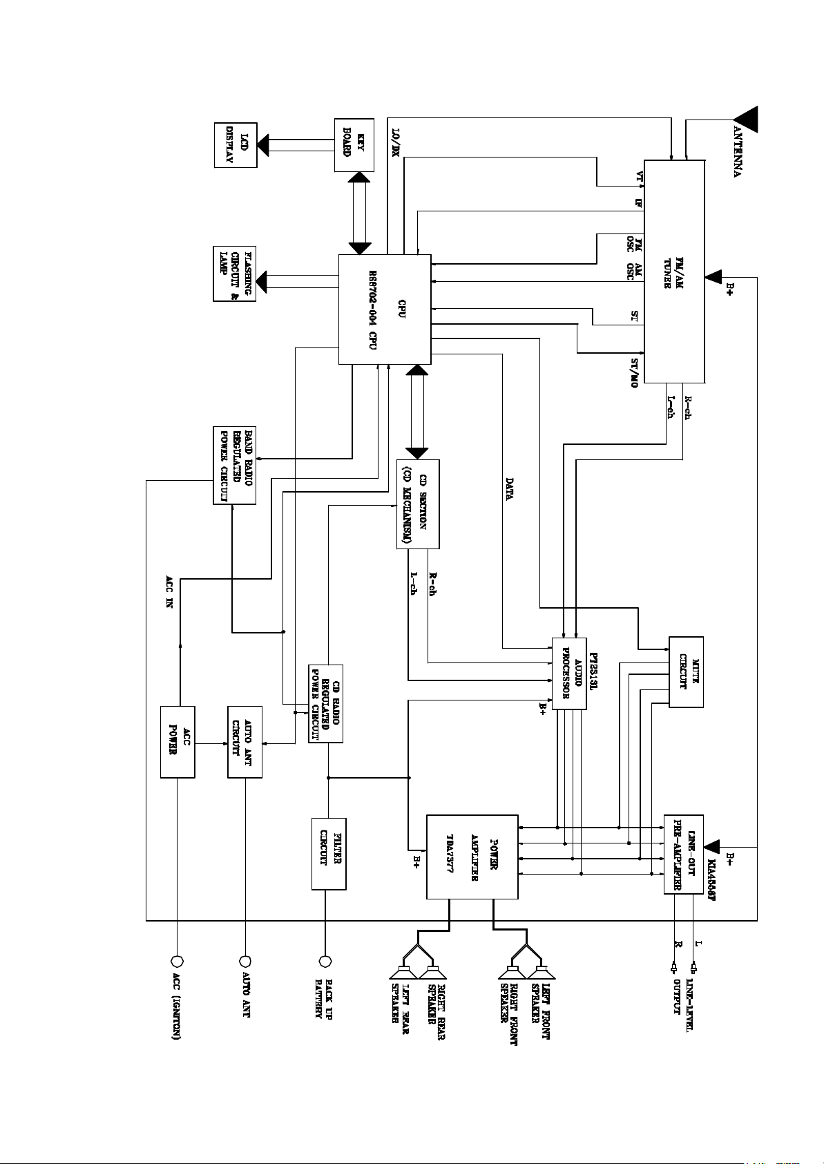
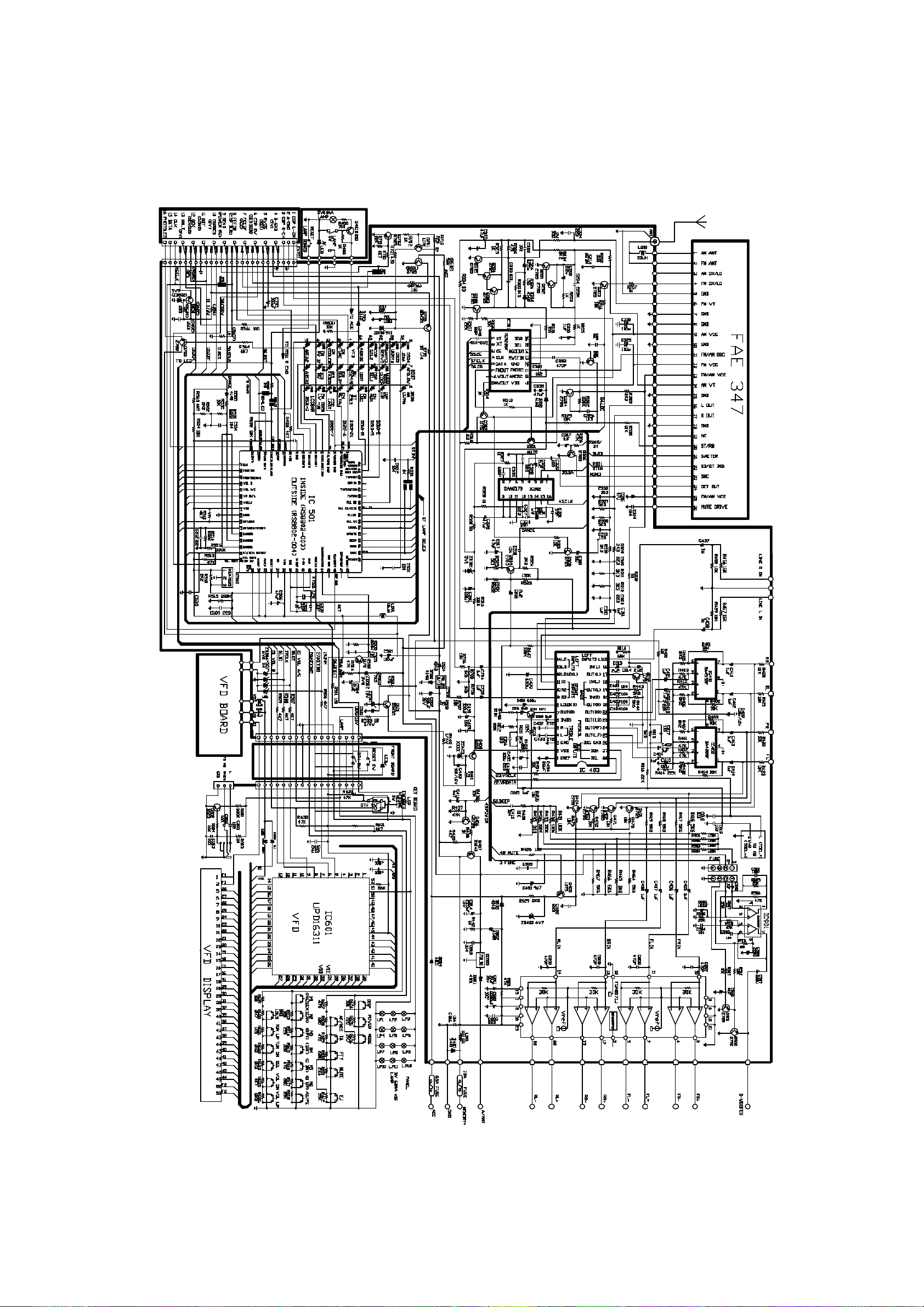
BLOCK DIAGRAM
6
Page 7
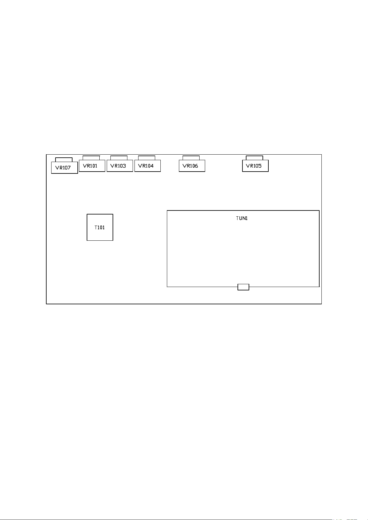
FM TUNER BOARD
ALIGNMENT LOCATIONS
7
Page 8

ALIGNMENT PROCEDURES
Limiting
FM ADJUSTMENT
Equipment Required
l AM IF/RF signal generator
l Solid-state voltmeter (SSVM)
l Regulated DC power supply
l 2-CH voltmeter
l Distortion meter
FM Alignment Using FM Signal Generator
Note: Press the radio power switch to on the radio. Signal generator output must be kept as low as possible
to avoid overload and clipping.
Step Generator
Coupling
IF FM RF signal
Generator to
Antenna
input.
76 kHz
Pilot
Modulation
-3 dB
Sens.
FM SNC
Adjustment
FM
Stereo
S/N
Auto
Stop
Sens.
Note: The tuner module is well-adjust and adjustment is not recommended.
Signal
generator
to antenna
receptacle
Signal
generator
to antenna
receptacle
98.1 MHz
Dev. 45 kHz
L+R=90 %
Int. 1 kHz
60dBµV output
Signal Generator
Connected to
Antenna
Signal Generator
Connected to
Antenna.
Generator Display
10.7 MHz
Sweep
output
60 dBµV
75 kHz Dev
45% for L only
or R only pilot
level 10%
60 dB/µV
Output.
98.1 MHz
@ 40 dB µ
98.1MHz
Int. 1kHz
Dev. 75kHz.
98.1 MHz Int. 1kHz
Dev. 75kHz
28 dB/µV.
98.1 MHz
98.1 MHz VR105
98.1 MHz
98.1 MHz
98.1MHz VR104
98.1 MHz
Setting
Adjustment Remarks
T101
VR101
VR106
VR107
Adjust so that
maximum AF
output power and
minimum distortion
Adjust to
76 kHz
Adjust VR101
Making -14dB
(±2dB) Limiting
Sensitivity.
VOR - VOL = 10 dB
(± 3 dB)
Adjust VR104 FM
Stereo S/N is the
optimum.
Adjustment
AF to stop station.
8
Page 9

MW ADJUSTMENT
Equipment Required
l AM IF/RF signal generator
l Solid-state voltmeter (SSVM)
l Regulated DC power supply
l 2-CH voltmeter
l Distortion meter
AM Alignment Using AM Signal Generator
Note: Press the radio power switch to on the radio. Signal generator output must be kept as low as possible
to avoid overload and clipping.
Step
AM
Seek
SENS.
Note: The tuner module is well-adjust and adjustment is not recommended.
Generator
Coupling
Signal
Generator
to Antenna
receptacle.
Generator
1000 kHz
Input level
25 dB µV
Display
Setting
1000 kHz VR1 Adjust AF
Adjustment
Remarks
Stop station.
9
Page 10

PRINTED CIRCUIT BOARDS
10
Page 11
Page 12
Page 13
5
4
3
2
1
C46 391
R23
R29
0
47K
C19 224
SLP
SLO
MDATA
FGD
FSI
R51
WDCK
RESET
30K
180K
120K
C51 683
EC12
10U
R28
C41
R31
2526272829303132333435
SLM
SPO
SPM
ASY
EFM
LOCK
CLV1
MLT
MCK
ISTAT
TGU
12
SVCC
VREF
104
222
104
104
C26
104
SGND
R55
2K2
C10
C5
C12
C13
24
23
22
21
20
19
18
17
16
15
14
13
3K9
22K
15K
103
150K
C66
R2
R39 270K
R1 47K
OPTION
open
R15
R13
C39 104
C65
104
C42
C44
R4
R52
472
C11
EC4
4U7
C32 open
68K
47K
37
LD
38
PD
39
PDAC
40
PDBD
41
PDF
42
PDE
43
DCB
44
MCP
45
DCCI
46
DCCO
47
VREF
48
EQC
8K2
8K2
C36
103
R380
R430
C57
222
36
TEIO
LPFT
ATSC
TZC/SSTOP
SIL9226
RFM
EQI
RFO
EQO
1324567891011
C37
C34
2P
102
RFO
R8220K
C38
TEO
SPLO
R71
EC9
47U
VREF
C25
SGND
SVCC
R12
10R
D D
J6
17
VCC
VREF
VEE
MD
VR
SGND
FO-
TRTR+
FO+
16
VREF
15
150K
14
E
B
C
D
A
F
LD
82K
13
82K
12
82K
11
82K
10
150K
9
8
82R
7
6
5
4
3
2
1
C27
104
R22
R58
R59
R61
R60
R21
R62
SGND
SGND
C40
103
Q1
104
SGND
VREF
SVCC
C45
C18
EC10
47U
391
104
LD
PD
AC
BD
F
E
103
103
C33
153
C24
104
2SA812
SGND
C C
C35
R53
1K
8P
104
J1
FEED+
FEED-
VREF
SVCC
SGND
VREF
1
2
SVCC
FEED
R75
+8V
J4
SPINDLE-
SPINDLE+
1
2
VREF
C56
104
SPINDLE
B B
SGND
GND
R76
8K2
open
R9
39K
21
22232425262728
1617181920
'
DI4.1
DI4.2
VERF
DO4.1
DO4.2
DI3
VCC1
VCC2
DO5.2
DO3.1
DO3.2
R18
R14
R77
SGND
TEO
FEO
TEM
FEM
SGND
U5
EFNI
VCC
FRSH
FSET
FIB
U3 KA9259
D01.1
D01.2
DI1.1
DI1.2
REB
REO
MUTE
GND
DI5.1
DI2
DI2.1
DI2.2
GND
DI5.2 DO5.1
SVCC
R30
1
2
3
4
3
2
1
SGND
R42 68K
39K
B+5V
GND
R40
47K
FEO
B+5V
R41
39K
J2
SLED+
SLED-
SLORG_IN
SLORG_OUT
SLED/ORGS/W
J5
GND
EJ END
A A
LD START
SENSOR
R63 68R
5
12345678910111213
R74
GND
D1
EL-23
R37
1K
5K6
+8V
R46
39K
R72
open
SW1
CHUCK S/W
D2
EL-23
SGND
VDD
SL+
SL-
AD/SW
14 15
R44 0
SLO
SGND
0
EC8
100uF
JR2
+8V
C55
104
GND SGND
75K
R11
R10
75K
GND
R34
R33
47K
47K
AGND
+8V
+3V
AGND
15
CD-1
8V DC
3V DC
DGND
OPTION
SENS1O
CD DATA
POWER RQ
4
B+5V
891011121314
CDPBUS
SENS1IN
1234576
RESET
A_GND
J3
B/UP(5V)
CDP LCH
CDP RCH
ACC(CDP ON)
103
R20
220K
R78 3K3
EFM
LOCK
CDCLK
OPTION
JR424K
JR115K
JR30
R57 15K
R27
PMOD
PWMOD
SPDLO
2K2
FEO
TEO
VREF
SLO
SP0
VREF
R3
10K
C29 474
R6 20K
R5 8K2
B+5V
C21
104
R65 1K
C43 474
C30
103
C31 333
GND
VDD
R67
470R
Q3
OPTION
3
SGND
A1504
ZD2
R71M
R32
2K2
3V6
ZD1
34
35
36
37
38
39
40
41
42
43
44
TP12
C4375
Q2
PWMOD
OPTION
C64
C63
33P
33P
R791M
X3
16.9344MHz
R56 15K
VREF
VCC
NC
NC
MLT
SQCK
POWERON
GND
CDPRES
BDATA
BUSOUT
MUTE
MCK1
AVDD
AVREF
RS9701 OR RS9702
8CMM
LKFS
1234567891011
2V
EC6
100uF
DGND
C28
222
CDCLK
GND
R54
JITB
ISTAT2
U2
SQDT
SLEDORG
220K
VDD
AGND
2K2
VDD
VDD
GND
ORGIN
ISTAT
VCC
R73
C20
104
C28
222
VCC
open
C70
C47
22P
4.5MHz
X1
OPTION1
GND
X2
X2
OPTION2
+3V3
1
2
3
4
5
6
7
8
9
10
11
12
103
C60
GND
C48
22P
R811M
2324252627282930313233
NC
NC
RESET
MP3INT
MP3MLAT
MP3DIN
MDATA
LSTART
AVSS
FEEDF
FEEDR
VCC
48
VSSA_PLL
VCO1LF
VSSD_PLL
VDDD_PLL
VDDD1-5V
XIN
XOUT
VSSD1
EFMI
LOCK
SMEF
SMDP
SMSD
WDCK
1314151617181920212223
102
GND
C6
22
GND
21
20
19
18
17
VDD1
16
MCK2
15
14
CDON
13
BUSIN
12
SOS1
VDD
47K
SEL3
SEL4
open
190K
R70 open
R26 2R2
C22
EC7
104
100uF
104
C14
EC3
10U
104
C15
EC2
10U
AGND
VCC
'''
VREF
VHALF
RCHOUT
VSSA_DAC
U6
S5L9290
46.VDDA_DAC
47.LCHOUT
48.VDDA_PLL
TESTV
LKFS
C4M
RESETB
MLT
GND
152
C50
RESET
R48
4K7
VDD
SEL2
SEL147K
SVCC
R24 2R2
R25 0
VCC
VDDD_DAC
MDAT
open
GND
2
AGND
ADATA
SADTI
VSSD_DAC
VDDD3-5V
VDDD2-3V
MCK
ISTAT
R56
VCC
24K
GND
GND
C23
104
AGND
BCKI
LRCK
3738394041424344454647
BCKI
LRCKI
BCKO
LRCKO
SADTO
DATX
C2PO
JTTB
SBCK
VSSD2
MUTE
SQDT
SOS1
SQCK
24
R19
R64470K
C67
OPEN
R17
100K
EC5
100uF
4M IC
1
D0
2
D1
3
WE
4
RAS
5
A9
6
A0
VCC DVCC
LCH
RCH
7
A1
8
A2
9
A3
10 11
VCC A4
R68
BCKI
GND
36
35
34
33
32
31
30
29
28
27
26
25
VCC
ADATA
C69
CDBCK
CDLRCK
CDDATA
GND
ACLK
VCC
VCC
R49
C59
OPEN
OPEN
152
C49
GND
C68 OPEN
EC11
10uF
C58
OPEN
R361K
GND
2K2
R16
100K
0
1
VCC
D0
2
DQ0
D1
3
C17
EC13
104
10uF
GND
R351K
C67
EC14
104
100uF
DQ1
4
WE
5
RAS
6
A11
7
A10
8
A0
9
A1
10
A2
11
A3
12 13
VCC VSS
16M IC
GND
MP3INT
MP3DIN
MP3MLAT
MCK2
MDATA
GND
GND
vcc2
C16
104
49
50
51
52
53
54
55
56
57
58
59
60
61
62
63
104
64
C54
GND
VCC
vcc2
33P
VCC
Title
Size Document Number Rev
A3
GND
CDX3.6.3(MP3)
{Doc} A
Date: Sheet of
48
VSS
VDD
DDAT2
DDAT3
CASB
DA08
DA07
DA06
DA05
DA04
DA09
DA00
DA01
DA02
DA03
OEB
VSS
VDD
1
R80 1M
X1
16.9344MHz
C2
C1
33P
WEB
RASB
TEST1
TEST2
TEST0
DDAT0
DDAT1
U1
S5L9274
15 PLL_BYPASS
XIXOXOUT
CLK
RESETB
PLLO VDDA
PLLO VSSA
2345678910
EC1
104
C7
100uF
MCK
MINT
MLAT
MDAT
MDOUT
SCAN_EN
CD/C2P0
CD/BCK
CD/LRCK
CD/DATA
CDP/CLK
ACLKEX
PLLO VBBA
FILTER_0
PLL1 VDDA
PLL1 VBBA
FILTER_1
PLL1 VSSA
1116131412
15
C3
C4102
821C8104
1 1Saturday, August 04, 2001
1
U7
GND
U4
333435363738394041424344454647
VDD
VSS
MCU_CLK
ETYPE
EMP
ADAT
LRCK
BCLK
ACLK
VDD
VSS
'
CAS
OE
VSS
DQ3
DQ2
CAS
QE
NC
NC
vcc2
D3
D2
A8
A7
A6
A5
A9
A8
A7
A6
A5
A4
vcc2
104
32
31
30
29
28
27
26
25
24
23
22
21
20
19
18
17
20
19
18
17
16
15
14
13
12
24
23
22
21
20
19
18
17
16
15
14
GND
C52
GND
GND
D3
D2
GND
vcc2
C53
104
PDF created with FinePrint pdfFactory trial version http://www.fineprint.com
Page 14

Page 15

Page 16

Page 17

Page 18

Page 19

Page 20

PDF created with FinePrint pdfFactory trial version http://www.fineprint.com
Page 21

PDF created with FinePrint pdfFactory trial version http://www.fineprint.com
Page 22

PDF created with FinePrint pdfFactory trial version http://www.fineprint.com
Page 23

PDF created with FinePrint pdfFactory trial version http://www.fineprint.com
Page 24

Page 25

Page 26

Page 27

PANEL
EXPLODED VIEW PARTS LIST
Ref. No.
1
2
3
4
5
6
7
8
9
10
11
12
13
14
15
16
Description RS Part No. Mfr’s Part No.
Lens; N/R CDD156X3.7.3 (S. OPC0000)
Panel Top For Fold Down (S. OPC0201)
Panel Bottom For Fold Down
M.P 156FX3.7.3 (Silver) VFD; N/Brand
Open Knob For Fold Down (S. OPC0201)
RE Knob Spring
VOL Knob (S. OPC0201)
VOL Ring (S. PMS291C)
VOL Ring Filter
MODE Knob (L-Up) (S. OPC0201)
SEL/P-EQ Knob (Crystal)
Base For SEL Knob (S. Plum red 198C)
DSP Knob (S. OPC0201)
1PAU Knob (L-Up) (S. OPC0201)
2SCN Knob (L-Up) (S. OPC0201)
3RPT Knob (L-Up) (S. OPC0201)
53-15654-35P
51-15621-80
51-15623-00
61-15601-812
52-15646-80
36-11852-00
52-15643-80
52-15647-70
44-15603-01
52-15626-81
52-15648-01B
52-15637-50R
52-15638-80
52-15627-81
52-15628-81
52-15629-81
17
18
19
20
21
22
23
24
25
26
27
28
29
30
31
32
33
4SHF Knob (L-Up) (S. OPC0201)
5 Knob (L-Up) (S. OPC0201)
6 Knob (L-Up) (S. OPC0201)
AMS Knob (L-Up) (S. OPC0201)
Power Knob For F. Down (L-Up) (S. OPC0201)
1-6 PVC Sheet
DSP/AMS Base
Tune/Track Down Knob (L-Up) (S. OPC0201)
Tune/Track Up Knob (L-Up) (S. OPC0201)
BND/LOU/MONO Knob (S. OPC0201)
LO/MU Knob (S. OPC0201)
VFD BJ883GNK (FUTABA) CDX3.2
Key Board
CD115 Rotate Encoder VOL
MODE Back Light (S. Milk)
SEL Back Light (S. White)
Middle Back Light
52-15630-81
52-15628-82
52-15631-81
52-15639-81
52-15635-81
35-15601-00
52-15650-00
52-15632-81
52-15633-81
52-15641-80
52-15642-80
27-B0883-00
12-01561-305
18-00115-00
52-15649-01
52-15653-01
52-15651-00
34
35
36
Right (Power) Back Light (S. White)
EJ Knob For F. Down (L-Up) (S. OPC0000)
Screw ∅2x8 BH/ST Black
52-15652-01
52-15636-31
40-12008-01
18
Page 28

CABINET
EXPLODED VIEW
19
Page 29

CABINET
EXPLODED VIEW PARTS LIST
Ref. No.
1
2
3
4
5
6
7
8
9
10
11
12
13
14
15
16
17
18
19
20
21
22
23
24
25
26
27
28
29
30
31
32
33
34
35
36
37
38
39
40
Description RS Part No. Mfr.’s Part No.
Panel
Ring +Spray Silver
Base/ABS (New Socket)
Front Cabinet /CD049X3.1
KMC CD MECHA. CDM -211S
Rear Cabinet
Top Cabinet
Bottom Cabinet
Main Fiber
Main Board
Heat Sink (Y) (W/O CDC)
Mounting Box
CD Windows Sheet
Shade (III)
Panel Bracket (CD)
Pipe
Bracket Spring
Gear 1 (POM)
Panel Bracket Spring (Left)
Panel Bracket Spring (Right)
GIB (POM)
Open Adaptor
Right Bracket
Gear 2 (POM)
Left Bracket
CD Back Light (PC)
Hook (POM)
Release Spring
Hook Shaft
Lamp Board
Socket Board
Socked Cover Nylon
Right Spring
Spring Bracket (PC)
Wire FIX Fiber
Wire FIX Sheet
Hook
Front Deck Bracket (X3.1)
Rear Deck Bracket
FM Cover
51-07122-80
51-04926-00
61-04912-02
94-00211-00
61-12622-00
61-12620-00
61-12621-00
35-12601-00
12-01360-088
61-12624-00
61-68707-08
43-A3101-00
81-69005-00
61-15603-00
34-40201-00
36-02922-00
52-40237-00
36-04901-00
36-04902-00
52-40235-00
52-10564-00
39-00104-00
52-40238-00
39-04908-00
52-04937-00
52-40236-00
36-00102-00
34-00101-00
12-03201-755
12-01000-345
52-10561-01
36-06855-01
52-04938-00
35-56704-00
39-04911-00
39-03207-00
39-03218-01
39-12621-00
39-09305-00
20
Page 30

Ref. No.
Description RS Part No. Mfr’s Part No.
41
42
43
44
45
46
47
48
49
50
51
52
53
54
55
56
57
IC 7805 Bracket
IC 8571 Bracket
Spring Washer M5
Screw M5 (Rear Cabinet)
Wire Clip
Antenna Clip (II)
Camera Screw M2X3 P/H (Black)
Screw ∅2 X 4 PA/ST
Screw ∅2 X 6 PA/ST Black
Screw ∅2.6 X 4 PH/MS
Screw ∅2.6X4 BH/MS
Screw ∅2.6 X 4 KH/MS
Screw ∅2.6 X 4 PH/TAPTITE
Screw ∅2.6X 6 BH/MS
Screw ∅2.6 X 8 BH/MS
Screw ∅2.6 X 12 BH/MS
Screw ∅3X16 PH/MS
39-03210-00
39-85712-00
35-50001-00
34-14461-00
39-12620-00
39-A1528-00
40-60203-20
40-02004-10
40-12006-20
40-02604-00
40-02604-01
40-02604-02
40-02604-03
40-02606-00
40-02608-01
40-02612-01
40-03016-00
21
Page 31

EXPLODED VIEW (DECK)
22
Page 32

Ref. No.
EXPLODED VIEW PARTS LIST (DECK)
Description Parts No. Q’ty
1
2
3
4
5
6
7
8
9
10
11
12
13
14
15
16
17
18
19
20
21
22
23
24
25
26
27
28
29
30
31
32
33
34
35
36
37
38
39
SENSOR
SENSOR PCB
SCREW
COVER-UPPER
LEVER DISC
GUIDE UP
BUSHING ROLLER
ROLLER DISC
SHAFT ROLLER
PIN ROLLER
PVC CAP
B/K ROLLER
PIN PULLEY
PIN IDLE
GEAR IDLE
GEAR PULLEY
BELT PULLEY
GEAR ROLLEY
LOCKER (L)
CAM (L)
S/P CAM (L)
S/P RACK
CAM (R)
LOCKER ®
GEAR RACK
GEAR LOAD ©
GEAR LOAD (D)
GEAR LOAD (B)
GEAR LOAD (A)
PIN LOAD
B/K GEAR
MOTOR
GEAR WORM
GERVO PCB ASSY
SPECIAL SCREW
S/P RO (L)
SUPPORT DAMPER
S/P RO ®
CHASSIS MAIN
ST-23G
FR
CA/H 0” TT 2*3
SECC T1.0
POM (F20-03)
POM (F20-03)
POM (F20-03)
SLICON
SUS 303
SUM24L-NI (PLATE)
PVC
SECC T1.0
SUM24L-NI (PLATE)
SUM24L-NI (PLATE)
POM (F20-03)
POM (F20-03)
CR-WRT
POM (F20-03)
POM (F20-03)
POM (F20-03)
SUS304WPB
SUS304WPB
POM (F20-03)
POM (F20-03)
POM (F20-03)
POM (F20-03)
POM (F20-03)
POM (F20-03)
POM (F20-03)
SUM24L-NI (PLATE)
SECC T1.0
FF-050SH-11190
POM (F20-03)
GLASS EPOXY 1.2T
P/H TTS 2*2
SUS304WPB
POM (F20-03)
SUS304WPB
SEEC T1.0
2
1
12
1
1
1
2
2
1
1
2
1
1
1
1
1
1
1
1
1
1
1
1
1
1
1
1
1
1
4
1
1
1
1
4
1
3
1
1
23
Page 33

Ref. No.
EXPLODED VIEW PARTS LIST – CONTINUED (DECK)
Description Parts No. Q’ty
40
41
42
43
44
45
46
47
48
49
50
51
52
53
54
55
56
57
58
59
60
61
62
63
64
65
66
67
68
69
70
71
72
73
CLAMP DISC
HOLD CLAMPER
S/P CLAMPER
TURN TABLE
BASE PU
PIN SIDE (A)
SCREW
PIN SIDE (B)
DAMPER
S/P BASE
MOTOR
GEAR PU (B)
GEAR PU (A)
SCREW
MOTOR
HOUSING GEAR
SHAFT PU
SCREW
4P CONT WIRE
SPRING TENSION
GEAR PU ©
LEAD SCREW
SWITCH
SCREW
PICK UP
FPC WIRE
SPRING PU
FIBER PAPER
S/P CAM ®
TRANSIT SCREW
INSULATOR COVER
SWITCH
WASHER PE
S/P BASE ®
POM (F20-03)
SECC T1.0
SUS304WPB
ABS G/F 20%
POM (F20-03)
SUM24L-NI (PLATE)
CA/H 0” M/S 1.7*2.5
SUM24L-NI(PLATE)
BUTHYL
SUS304WPB
RF-400CA-12265
HYTRELL 5526
POM (F20-03)
CA/H 0” M/S 2*2
FF-050SH-11190
POM (F20-03)
KNN11 (PCD18)
R/H (W/W) TTB2*5
1007 #28
SUS304WPB
POM (F20-03)
BSBM
SW-110
B/H TTB1.7*8
SF-C99
POLY AMIDE
SUS T0.2
0.55
4.5*18
PE
SW-111
PE
SUS304WPB
1
1
1
1
1
2
2
2
1
2
1
1
1
6
1
1
1
1
1
1
1
1
1
1
1
1
1
1
1
2
1
1
2
2
24
Page 34

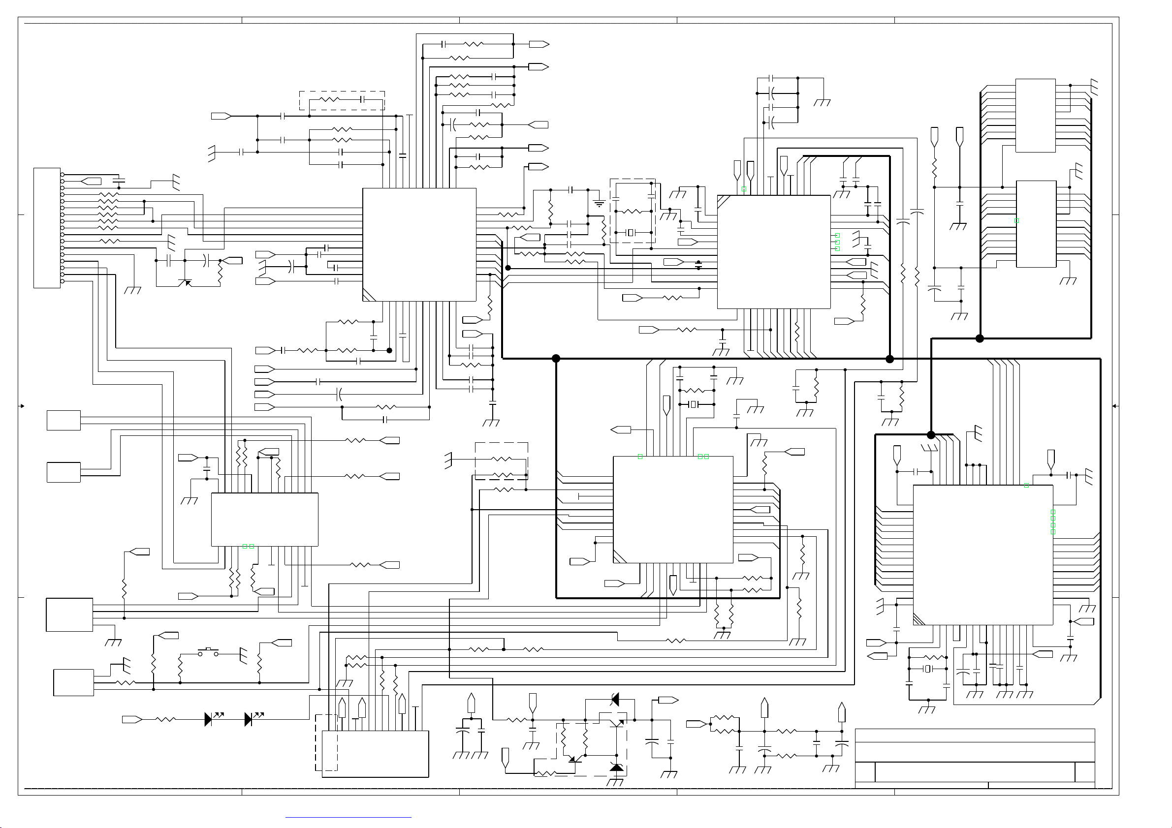
SCHEMATIC DIAGRAM (MAIN)
25
Page 35

SCHEMATIC DIAGRAM (SERVO)
26
Page 36

ELECTRICAL PARTS LIST
Ref. No. Part No. Description Q’ty
Q501,705
Q301,405,502,701
Q407
Q203,303~7,401~4/6,504,702
IC502
D801,804
D513/4,502/4/5,535,304/5,802/3,533/5/
6,703
D400
ZD502
ZD402
ZD301
ZD504~7
ZD703
ZD501
IC403
IC401/2
IC302
IC503
IC801
IC803
IC501
IC301
XT501
XT301
C510/1
C330/1
C321,512
C322/3/9,505,326
C314,420/15,514/8,532,815/6,215,
531
C319/20,312/3
C346
C327/8,334,436,452,509,803
C432/3
C807~10
C333
C421~4
C350,410/9,435,521,701,703
C912/3
C335~7,316,506,517
C310/11/17,401~8,411~4,704/5
C811
PC BOARD ASSY, MAIN BOARD
01-00435-00
01-01175-00
01-01240-00
01-02785-00
01-07805-00
02-04001-00A
02-04148-00A
02-05401-00
02-50036-00A
02-50047-00A
02-50051-00A
02-50068-00A
02-50091-00A
02-50100-00
03-02313-00
03-04558-06
03-06579-00
03-07035-00
03-07377-00
03-07818-00
03-08802-004
03-09257-00
04-00072-00
04-00433-00M
05-00330-06
05-00390-06
05-05102-00A
05-05103-00A
05-05104-00A
05-05153-00A
05-05220-00A
05-05223-00A
05-05272-00A
05-05471-00A
05-05681-00A
05-06164-82
06-10107-01
06-10108-01
06-10476-01
06-16105-01
06-16106-01
TRANSISTOR BD435 “SAM SUNG”
TRANSISTOR 2SA1175-FF
TRANSISTOR B1240
TRANSISTOR 2SC2785-FF
IC-REGULATOR 78L05
DIODE IN4001 (TAPPING)
DIODE 1N-4148 (TAPPING)
DIODE IN5401
ZENER DIODE 3.6V 0.5W AT.
ZENER DIODE 4.7V 0.5W AT.
ZENER DIODE 5.1V 0.5W AT.
ZENER DIODE 6.8V 0.5W AT.
ZENER DIODE 9.1V 0.5W AT.
ZENER DIODE 10V 0.5W
I.C. PT2313L
IC KIA -4558F
IC. SAA-6579T
IC KIA7035P
I.C. TDA -7377 (PWR)
REGULATOR LC-78L18
IC RS8802-004
I.C. TC 9256P
CRYSTAL HC-49/US 7.2MHZ
C. 4.332SMHz HC-49U 30PPM 22PF
CER CAP 33P NPO ±5%
CER CAP 39P NPO ±5%
AXIAL CER CAP 1000PF ±20% TP.
AXIAL CER CAP 0.01µF+80/-20% TP.
AXIAL CER CAP 0.1µF +80/ -20% TP.
A. CER CAP 0.015µF +80/ -20% TP.
AXIAL CER CAP 22PF ±5%
A. CER CAP 0.022µF +80/ -20% TP.
AXIAL CER CAP 2700PF ±20% TP
AXIAL CER CAP 470PF ±10% TP.
AXIAL CER CAP 680PF ±10% TP.
AXIAL CER CAP 0.1µF X7 R ±10% TP.
E. CAP 100µF 10V (∅5X7MM MINI)
E. CAP 1000µF 10V (∅8X14MM)
E. CAP 47µF 10V (∅4X7 MINI)
E. CAP 220µF 10V ∅6MM
E. CAP 10µF 10V (∅4X7MM)
2
4
1
13
1
2
14
1
1
1
1
4
1
1
1
2
1
1
1
1
1
1
1
1
2
2
2
5
10
4
1
7
2
4
1
4
7
2
6
17
1
27
Page 37

ELECTRICAL PARTS LIST - CONTINUED
Ref. No. Part No. Description Q’ty
C409,502,513
C011/4,332,504,516
C434
C814
C801
C451,416
C911
C324
C429,430
R715,440,533
R318
R305,502,327/8
R511,321,316
R319/31,438/42,325,702
R216,706/7,426/30/36,454/5,47
0~3,530,555,329,338
R431~4
R324
R323
R523,447/8
R708/9,518
R554
R501
R429,512,562
R413/4,711/3/4
R505/15/22/14
R334,330
R435,J24
R307~10,524
R556
R701,326
R428,439,506~10,710
R306,409~12,437,504,801,
R563
R525
R311/2,416~9,443/4
R453,415
R503
R405~8
R531
L501
MB
L801
06-16107-01
06-16225-01
06-16226-01
06-16227-01
06-16338-00S
06-16475-01
06-16476-01
06-50224-01
06-50334-01
07-05010-00
07-05022-16A
07-05100-16A
07-05101-16A
07-05102-16A
07-05103-16A
07-05104-16A
07-05151-16A
07-05152-16A
07-05154-16A
07-05182-16A
07-05183-16A
07-05221-16A
07-05222-16A
07-05223-16A
07-05224-16A
07-05330-16A
07-05331-16A
07-05332-16A
07-05334-16A
07-05471-16A
07-05472-16A
07-05473-16A
07-05475-16
07-05512-16A
07-05562-16A
07-05680-16A
07-05752-16A
07-05822-16A
07-05824-16A
09-70100-01
12-01360-008
15-27014-01
E. CAP 100µF 10V (∅6.3X7MM)
E. CAP 2.2µF 16V ∅4X7
E. CAP 22µF 16V (∅4X7MM)
E. CAP 220µF 16V (∅6.3X12MM)
E. CAP 3300µF 16V 105°C
E. CAP 4.7µF 16V (∅4X7MM)
E. CAP 47µF 16V (∅5X7MM)
E. CAP 0.22µF 50V (∅4X7MM) MINI
E. CAP 0.33µF 50V (∅4X7MM)
RES. 1Ω 1/4W
RES. 2.2Ω 1/16W (TAPPING)
RES. 10Ω 1/16W (TAPPING)
RES. 100Ω 1/16W (TAPPING)
RES. 1k Ω 1/16W (TAPPING)
RES. 10k Ω 1/16W(TAPPING)
RES. 100k Ω 1/16W (TAPPING)
RES. 150Ω 1/16W (TAPPING)
RES. 1.5k Ω 1/16W (TAPPING)
RES. 150k Ω 1/16W (TAPPING)
RES. 1.8k Ω 1/16W (TAPPING)
RES. 18k Ω 1/16W (TAPPING)
RES. 220Ω 1/16W (TAPPING)
RES. 2.2k Ω 1/16W (TAPPING)
RES. 22k Ω 1/16W (TAPPING)
RES. 220k Ω 1/16W (TAPPING)
RES. 33Ω 1/16W (TAPPING)
RES. 330Ω 1/16W (TAPPING)
RES. 3.3k Ω 1/16W (TAPPING)
RES. 330k Ω 1/16W (TAPPING)
RES. 470Ω 1/16W (TAPPING)
RES. 4.7k Ω 1/16W (TAPPING)
RES. 47k Ω 1/16W (TAPPING)
RES. 4.7MΩ 1/16W ±5%
RES. 5.1k Ω 1/16W (TAPPING)
RES. 5.6k Ω 1/16W (TAPPING)
RES. 68Ω 1/16W (TAPPING)
RES. 7.5k Ω 1/16W (TAPPING)
RES. 8.2k Ω 1/16W (TAPPING)
RES. 820k Ω 1/16W (TAPPING)
MICRO INDUCTOR 10UH AXIAL TYPE
PCB CDDX3.7.3 VMB 188X145
RING COIL Ø27X14MM V-TYPE
3
5
1
1
1
2
1
1
2
3
1
4
3
6
16
4
1
1
3
3
1
1
3
5
4
2
2
5
1
2
8
9
1
1
8
2
1
4
1
1
1
1
28
Page 38

Ref. No. Part No. Description Q’ty
Q104/6
Q102
D107
D106
IC101
IC102
C136
C115/6
C122
C117
C126
C123
C121
C135,001/2
C109,129,133
C108/9,111/2/8
C130
C114
C134
C102
C113,128,132
C110,125/7,131
C124
J01~5
R114
V104
VR106
R119
R116/8
R136
J5~15,R152
R128,J16
R109,133,108,129
R103,149,117,112
R113,132
R150
R115
R120
R107,110,134
R106,135
R111
R120
ELECTRICAL PARTS LIST - CONTINUED
PC BOARD ASSY, FM TUNER BOARD
01-02785-00C
01-03875-07
02-04148-00
02-04148-02
03-01140-00
03-03375-00
05-03102-10
05-03223-10
05-05103-10H
05-05330-00H
05-05333-00
05-09102-11
05-63102-01
05-63103-01
05-63104-01
05-63223-01
05-63332-01
06-10107-01
06-10227-01
06-16106-01
06-16475-01
06-50105-01
06-50335-02C
07-05000-54
07-05123-16
07-05203-16
07-05392-16
07-05472-16
07-05473-16
07-05824-54
07-63000-00
07-63100-00
07-63102-00
07-63103-00
07-63153-00
07-63222-00
07-63223-00
07-03224-00
07-63331-00
07-63392-00
07-63473-00
07-63683-00
TRANSISTOR 2SC2785 “NEC”
TRANSISTOR 2SC3875G
DIODE IN-4148
DIODE CHIP PLS4148 1206 ROHM
I.C. LA -1140
I.C. LA -3375
CHIP CER CAP 1000P 50V K Y5P TA
CHIP CAP CM21X7R223K25AT
AXIAL CER UP050B103K -B-B7 ±10%
AXIAL UP050SL 330J-B-B (±5%)
AXIAL CER CAP 0.33µF +80/ -20%
POLY CAP 1000PF ±5%
CHIP 1000PF ±10% X7R 0603 SMT
CHIP 0.01µF ±10% X7R 0603 SMT
CHIP 0.1µF ±10% X7R 0603 SMT
CHIP 0.022µF ±10% X7R 0603 SMT
CHIP 3300PF ±10% X7R 0603 SMT
E. CAP 100µF 10V (∅5X7MM MINI)
E. CAP 220µF 10V (∅6MM MINI)
E. CAP 10µF 16V (∅4X7MM)
E. CAP 4.7µF 16V (∅4X7MM)
E. CAP 1µF 50V (∅4X7MM)
E. CAP 3.3µF 50V (∅3X5MM)
CHIP RES. 0Ω 1/10W
RES. 12kΩ 1/16W
RES. 20kΩ 1/16W ±5%
RES. 3.9kΩ 1/16W
RES. 4.7kΩ 1/16W
RES. 47kΩ 1/16W
CHIP RES. 820kΩ 1/10W
CHIP RES. 0Ω 0603 SMT
CHIP RES. 10Ω ±5% 0603 SMT
CHIP RES. 1kΩ ±5% 0603 SMT
CHIP RES. 10kΩ ±5% 0603 SMT
CHIP RES. 15kΩ ±5% 0603 SMT
CHIP RES. 2.2kΩ ±5% 0603 SMT
CHIP RES. 220kΩ ±5% 0603 SMT
CHIP RES. 22kΩ ±5% 0603 SMT
CHIP RES. 330Ω ±5% 0603 SMT
CHIP RES. 3.9kΩ ±5% 0603 SMT
CHIP RES. 47kΩ ±5% 0603 SMT
CHIP RES. 68kΩ ±5% 0603 SMT
2
1
1
1
1
1
1
2
1
1
1
1
1
3
3
5
1
1
1
1
3
4
1
5
1
1
1
1
2
1
12
2
4
4
2
1
1
1
3
2
1
1
29
Page 39

Ref. No. Part No. Description Q’ty
R127
CF101/2
VR103
VR107
VR105
VR101
Q302
Q202/1,308,310
D528
C214,204
C205
C318
C210
R203/5,304
R336
R337,350
R202
R204
L201
VR1
LED1
LP1~11
IC601
C604/5
C606~10/12~15
C601
C616
R651~4
R609,621,655/6
R646~650
639/40/41
R610/22
R604/16
R627/15
R605,61
R611/23
R606/18
R612/24
R619,607
ELECTRICAL PARTS LIST - CONTINUED
07-63752-00
08-70174-01
09-10710-01
12-01140-135
17-30103-06S
17-30104-06S
17-30502-06S
17-30503-06S
PC BOARD ASSY, AM TUNER BOARD
01-01175-00
01-02785-00
02-04148-00A
05-05223-00A
05-16225-00
06-10107-01
06-16105-01
07-05102-16A
07-05103-16A
07-05223-16A
07-05331-16A
07-05822-16A
09-70330-01
17-31203-06T
PC BOARD ASSY, KEY BOARD
02-01112-00F
02-30553-60T
03-16311-00
05-03105-10M
05-63101-00
05-63104-01
05-63221-00
07-63101-00
07-63102-00
07-63103-00
07-63151-00
07-63152-00
07-63181-00
07-63183-00
07-63221-00
07-63222-00
07-63331-00
07-63332-00
07-63471-00
CHIP RES. 7.5kΩ ±5% 0603 SMT
TFT 10.7MHZ H=7.5MM
FILTER SEF 10.7MJ ‘MURATA’ ±30K
LA1140 TUNER BOARD 74X40X1.2
SEMI-FIXED EVND2AA03B14 (10KB)
SEMI-FIXED EVND2AA03B15 3V
SEMI-FIXED EVND2AA03B53
SEMI-FIXED EVND2AA03B54 (50K Ω)
TRANSISTOR 2SA1175-FF
TRANSISTOR 2SC2785-FF
DIODE IN-4148 AT. (TAPPING)
A. CER CAP 0.022µF +80/ -20% TP.
TAN CAP 2.2µF 16V
E. CAP 100µF 10V (Ø5X7MM MINI)
E. CAP 1µF 16V (Ø4X7MM)
RES. 1k O 1/16W (TAPPING)
RES. 10k O 1/16W (TAPPING)
RES. 22k O 1/16W (TAPPING)
RES. 330O 1/16W (TAPPING)
RES. 8.2k O 1/16W (TAPPING)
MICRO INDUCTOR 33µH AXIAL TYPE
SEMI-FIXED SC-065 B20K Ø6MM 3H
SMD LED PG1112H GREEN “STANLEY”
P.LAMP AA 3V 60MA Ø3X5.5 K.T.
IC µPD16311GC (VFD DRIVER)
CHIP CAP KC20E1C105M-TS
CHIP 100PµF ±5% NPO 0603 SMT
CHIP 0.1µF ±10% X7R 0603 SMT
CHIP 220PF ±5% NPO 0603 SMT
CHIP RES 100? ±5% 0603 SMT
CHIP RES 1k? ±5% 0603 SMT
CHIP RES. 10kΩ ±5% 0603 SMT
CHIP RES 150? ±5% 0603 SMT
CHIP RES. 1.5kΩ ±5% 0603 SMT
CHIP RES. 180Ω ±5% 0603 SMT
CHIP RES 18k?
CHIP RES. 220Ω ±5% 0603 SMT
CHIP RES. 2.2kΩ ±5% 0603 SMT
CHIP RES. 330Ω ±5% 0603 SMT
CHIP RES. 3.3kΩ ±5% 0603 SMT
CHIP RES. 470Ω ±5% 0603 SMT
1
1
2
1
1
1
1
1
1
4
4
2
1
1
1
3
1
2
1
1
1
1
1
11
1
2
9
1
1
4
4
5
3
2
2
2
2
2
2
2
2
30
Page 40

ELECTRICAL PARTS LIST - CONTINUED
Ref. No. Part No. Description Q’ty
R613,625,601
R643~4
R603
R620,608
R614,626
L601
KB
SW
Q1
Q601
Q602
D1,2
ZD2
ZD602
U5
U3
U1
U6
U2
X2
X1
C602
EC2/3,11~13
EC4
C34
C35
C4,6,37
C30,38,40~42,44,60/61,66
C7~18,20~27,39,52~56,62,65
C49,50
C33
C47,48
C5,28,57
C19
C1,2
C31
C45
C36,46
07-63472-00
07-63473-00
07-63563-00
07-63681-00
07-63822-00
09-70100-01
12-01561-305
16-01107-00K
16-01140-04
PC BOARD ASSY, SDK/CD SERVO BOARD
01-00812-00
01-02785-00
01-08050-03
02-00144-00
02-04148-00
02-50020-00
02-50039-00A
03-09226-00
03-09259-00
03-09274-00
03-09290-00
03-09702-001
03-M1644-00
04-00050-00
04-00169-00
05-05223-00A
05-25106-10
05-25475-10
05-63020-00
05-63080-00
05-63102-01
05-63103-01
05-63104-01
05-63152-01
05-63153-01
05-63220-00
05-63222-01
05-63224-01
05-63330-00
05-63333-01
05-63391-00
05-63472-01
CHIP RES. 4.7kΩ ±5% 0603 SMT
CHIP RES 47k? ±5% 0603 SMT
CHIP RES. 56kΩ ±5% 0603 SMT
CHIP RES. 680Ω ±5% 0603 SMT
CHIP RES. 8.2k Ω ±5% 0603 SMT
MICRO INDUCTOR 10UH AXIAL TYPE
PCB CD-F156VFD KB 159X41.8
TACT SW. DCT/1101 4.3MM 2PIN
TACT SW. KPS-1107SW H=2.5 KIE
TR. 2SA812
TRANSISTOR 2SC2785-FF
TR. 8050C TO -92-B
IR LED MIE 144A1MC
DIODE IN-4148
ZENER DIODE 2V 0.5W
ZENER DIODE 3.9V 0.5W AT.
IC SIL 9226
IC KA9259D
IC S5L9274
IC S5L 9290
IC RS9702-001 (FOR MP3)
FILTE M11L1644SA-60J 4X4M DRAM
CRYSTAL HC-49/US 5MHZ
CRYSTAL HC-49/US 16.934MHZ
A. CER CAP 0.022µF +80/ -20%
TAN CAP CHIP 10µF 25V 1206 SMT
TAN CAP CHIP CER 4.7µF 25V 1206 SMT
CHIP CER 2PF ±5% NPO 0603 SMT
CHIP CER 8PF ±5% NPO 0603 SMT
CHIP 1000PF ±10% X7R 0603 SMT
CHIP 0.01µF ±10% X7R 0603 SMT
CHIP 0.1µF ±10% X7R 0603 SMT
CHIP 1500PF ±10% X7R 0603 SMT
CHIP 0.015µF ±10% X7R 0603 SMT
CHIP CER 22PF ±5% NPO 0603 SMT
CHIP 2200PF ±10% X7R 0603 SMT
CHIP 0.22µF ±10% X7R 0603 SMT
CHIP CAP 33PF ±5% NPO 0603 SMT
CHIP 0.033µF ±10% 0603 SMT
CHIP 390PF ±5% NPO 0603 SMT
CHIP 4700PF ±10% X7R 0603 SMT
3
2
1
2
2
1
1
17
2
1
1
1
2
1
1
1
1
1
1
1
1
1
1
1
1
5
1
1
1
3
9
28
2
1
2
3
1
2
1
1
2
31
Page 41

Ref. No. Part No. Description Q’ty
C29,43
C51
C3
EC1,5~8,14
EC9,10
J84
MP36
R601
R607
R609
R608
R602
JR2,3,25,38,43~45,66,68
R24,26
R12
R15~37,53
R3
R16,17,23
R7
R77
R28,56,57
R21,22,31
R6
R27,49,54,55
R2
R8,14,20,73
R19
R39
R18
R51
R9,30,41,46
R48,78
R1,13,33,34,40,SEL1,2
R64
R74
R63
R15,29,42
R10,11
R62
R4,5,52,76
R58~61
R
SW1
ELECTRICAL PARTS LIST - CONTINUED
05-63474-00
05-63683-01
05-63821-00
06-16107-54
06-16476-54
07-05100-00
07-05101-16A
07-05103-16A
07-05105-16A
07-05221-16A
07-05332-16A
07-05563-16A
07-63000-00
07-63022-00
07-63100-00
07-63102-00
07-03103-00
07-63104-00
07-63105-00
07-63124-00
07-63153-00
07-63154-00
07-63203-00
07-63222-00
07-63223-00
07-63224-00
07-63243-00
07-63274-00
07-63303-00
07-63392-00
07-63393-00
07-63472-00
07-63473-00
07-03474-00
07-03562-00
07-03680-00
07-63683-00
07-63753-00
07-63820-00
07-63822-00
07-63823-00
12-87020-630
16-00033-01
CHIP CAP 0.47µF ±5% (+80/ -20%)
CHIP 0.068µF ±10% 0603 SMT
CHIP 820PF ±5% 0603 SMT
E. CAP CHIP 100µF/16V Ø6.3X5.5
E. CAP CHIP 47µF/16V Ø5X5.5
RES. 10Ω 1/4W
RES. 100Ω 1/16W (TAPPING)
RES. 10k Ω 1/16W (TAPPING)
RES. 1MΩ 1/16W (TAPPING)
RES. 220Ω 1/16W (TAPPING)
RES. 3.3k Ω 1/16W (TAPPING)
RES. 56k Ω 1/16W (TAPPING)
CHIP RES. 0Ω 0603 SMT
CHIP RES. 2.2Ω ±1% 0603 SMT
CHIP RES. 10Ω ±5% 0603 SMT
CHIP RES. 1k Ω ±5% 0603 SMT
CHIP RES. 10k Ω ±5% 0603 SMT
CHIP RES. 100k Ω ±5% 0603 SMT
CHIP RES. 1MΩ ±5% 0603 SMT
CHIP RES. 120k Ω ±5% 0603 SMT
CHIP RES. 15k Ω ±5% 0603 SMT
CHIP RES. 150k Ω ±5% 0603 SMT
CHIP RES. 20k Ω ±5% 0603 SMT
CHIP RES. 2.2k Ω ±5% 0603 SMT
CHIP RES. 22k Ω ±5% 0603 SMT
CHIP RES. 220k Ω ±5% 0603 SMT
CHIP RES. 24k Ω ±5% 0603 SMT
CHIP RES. 270k Ω ±5% 0603 SMT
CHIP RES. 30k Ω ±5% 0603 SMT
CHIP RES. 3.9k Ω ±5% 0603 SMT
CHIP RES. 39k Ω ±5% 0603 SMT
CHIP RES. 4.7k Ω ±5% 0603 SMT
CHIP RES. 47k Ω ±5% 0603 SMT
CHIP RES. 470k Ω ±5% 0603 SMT
CHIP RES. 5.6k Ω ±5% 0603 SMT
CHIP RES. 68Ω ±5% 0603 SMT
CHIP RES. 68k Ω ±5% 0603 SMT
CHIP RES. 75k Ω ±5% 0603 SMT
CHIP RES. 82Ω ±5% 0603 SMT
CHIP RES. 8.2k Ω ±5% 0603 SMT
CHIP RES. 82k Ω ±5% 0603 SMT
PCB MP3/KMC SERVO (D/SIDE)
MICRO SWITCH MPU10371MLBO (MIC)
2
1
1
6
2
1
1
1
1
1
1
1
9
2
1
4
1
3
1
1
3
3
1
4
1
4
1
1
1
1
4
2
7
1
1
1
3
2
1
4
4
1
1
32
Page 42

Ref. No. Part No. Description Q’ty
R420/1/2/3
RCA
Q402
LED
LAMP
R408
R406
RESET
SW
Q002
Q001
D001~3
Z001/3
Z002
C005
C004
Q002 “C” TO “GND”
C001
C0001
C002
C003
ZD003 TO COIL
R006
R002
R004
R007
R005
R001
B+
L000
ELECTRICAL PARTS LIST - CONTINUED
PC BOARD ASSY, LINEOUT BOARD
07-05223-16A
20-20200-08
PC BOARD ASSY, FRONT PCB & DETACHABLE BOARD
12-01000-345
25-F5768-15
PC BOARD ASSY, LAMP BOARD
01-08050-03
02-30000-02
02-30553-60T
07-05102-16
07-05151-00
12-03201-755
16-01105-00K
16-51377-00K
PC BOARD ASSY, EL DRIVER BOARD
01-00435-00S
01-02785-00
02-04148-00
02-50068-00
02-50120-00
05-00104-82
05-02128-10
05-03474-10M
06-16227-01
06-16475-01
06-16476-00
06-50336-00
07-05047-16
07-05152-16
07-05223-16
07-05272-16
07-05333-16
07-05471-16
07-05561-16
07-05682-16
09-70100-01
09-70270-01
12-09368-900
15-00013-00
RES. 22kΩ 1/16W (TAPPING)
DOUBLE RCA CABLE 200MM GREY
FLEXIBLE PCB CDD100X3.2
15PIN SOCKET
TR. 8050C TO -92-B
LED Ø3MM RED
P.LAMP AA 3V 60MA Ø3X5.5 K.T.
RES 1k? 1/16W
RES 150? 1/16W
PCB CD-032X2 LB 1.0MM 41X18
TACT SW. 4P 7MM 160G (1102B)
PUSH SW. SPP51377A (DS -20) KONEX
TRANSISTOR BD435 “SAM SUNG”
TRANSISTOR 2SC2785-FF
DIODE IN-4148
ZENER DIODE 6.8V 0.5W
ZENER DIODE 12V BZX55-C12 ITT
CRE CAP 0.1µF 25V
MYLAR CER 0.0018µF ±10%
CHIP CER KC20E1C474M-TP
E. CAP 220µF 16V (Ø6.3X12MM)
E. CAP 4.7µF 16V (Ø4X7 MINI)
E. CAP 47µF 16V (Ø5X11 MM)
E. CAP 33µF 50V
RES. 4.7Ω 1/16W
RES. 1.5k Ω 1/16W
RES. 22k Ω 1/16W
RES. 2.7k Ω 1/16W
RES. 33k Ω 1/16W
RES. 470Ω 1/16W
RES. 560Ω 1/16W
RES. 6.8k Ω 1/16W
MICRO INDUCTOR 10UH AXIAL TYPE
COIL 27UH AXIAL TYPE (10MM)
PCB 09368 (VFD) DRV
VFD TRANS EE-13 SAGAMI
4
1
1
1
1
1
1
1
1
1
1
1
1
1
3
2
1
1
1
1
1
1
1
1
1
1
1
1
1
1
1
1
1
1
1
1
33
Page 43

SPECIFICATIONS
T. H. D·························································································································· Less than 0.35%
Signal to Noise Radio ····································································································· More than 60 dB
Channel Separation ········································································································· More than 60 dB
Frequency Response···············································································································20Hz-20kHz
Stereo separating (FM) ····································································································· 30 dB (at 1kHz)
Signal to noise ratio (FM)·································································································Better than 50 dB
Output power ······························································································································ 4 X 40W
Speaker output impedance········································································································4 To 8 ohm
Power source······································································································DC 12V, Negative ground.
Frequency range ·········································································································FM 87.5 - 108.0MHz
··································································································································· MW 522-1620 kHz
·····································································································································LW 144 - 288 kHz
Sensitivity··················································································································FM 3 µV (S/N=30dB)
···························································································································MW 32 dBµ (S/N=20 dB)
····························································································································LW 35 dBµ (S/N=20 dB)
Specifications are subject to change without notice.
34
 Loading...