

Page 1
Fu seM aster 76 511
Installation and
Time Tested • Time Proven
operating instructions
855429-00 06/15
ROADMASTER, Inc. 6110 NE 127th Ave. Vancouver, WA 98682 800 -669-9690 Fax: 360-735-9300 www.roadmasterinc.com
Purpose
The FuseMaster 76511 will eliminate the necessity of having to remove a fuse for towing, then reinserting it for driving.
After the installation you will flip a switch to accomplish the
same purpose.
The FuseMaster 76511 is for vehicles which must have one
ATM mini or one ATM micro fuse (not included) removed. It
is specifically designed for installations where the distance
between the fuse to be removed and the closest switch
mounting location is approximately 12 or 13 inches.
(The FuseMaster 76510 is for the same type of installation,
but three inches shorter.)
For a vehicle-by-vehicle fit list, visit www.roadmasterinc.
com. Select the “Vehicle-Specific Info” menu tab.
Required tools
• fuse puller (for difficult-to-access fuses)
• power drill with ¾-inch bit or ¾-inch flat auger bit
All specifications are subject to change without notice.
Installation instructions
CAUTION
Read all instructions before installing or
operating this device. Failure to understand
how to properly install or operate the FuseMaster could result in extensive property
damage.
Note: if the fuse to be removed is located in the engine
compartment, see “Engine compartment installation,” at the
end of these instructions.
1. Refer to the towed vehicle owner's manual to determine
which fuse must be removed for towing.
Note: running changes may not be reflected in the owner’s
manual. ROADMASTER recommends calling the dealership to
confirm which fuses must be removed.
2. Remove the access panel and then the fuse.
3. Confirm that the two silver pins at the end of the FuseMaster harness are the same size as the pins on the fuse you
removed. The pins must match.
Safety Definitions
These instructions contain information that is very important to know and understand. This information is provided for safety and to prevent equipment problems.
To help recognize this information, observe the following:
WARNING indicates a potentially hazardous situation which, if not avoided, could result in property
damage, serious personal injury or even death.
CAUTION
CAUTION indicates a potentially hazardous situation which, if not avoided, may result in property
damage.
NOTE
Refers to important information and is placed in italic
type. It is recommended that you take special notice of
these items.
CAUTION
Do not insert the fuse into the FuseMaster harness until
instructed to do so, or the fuse may blow.
Note: if the fuse is an ATM micro fuse, you must purchase
an ATM mini fuse of the same amperage to replace it — a micro
fuse will not fit in the FuseMaster fuse holder.
4. Insert the two silver pins at the end of the FuseMaster
harness into the socket for the fuse you removed. Either pin
will work in either hole.
Gently press the pins down until they are fully seated.
Note: for vehicles with ATM micro fuses (for example, some
Honda models), press the silver pins to the outside edges of the
fuse socket — the sockets for these fuses have the connectors
at the sides.
You may find it easier to use the included fuse socket
continued on next page
Notice
ROADMASTER, Inc. assumes no responsibility for
damage and accepts no liability in any way for the proper
or improper use or installation of this product, including
any warranty claims that may be considered voided by
the towed vehicle manufacturer or for any consequential
damage that may arise from its use.
Page 2
continued from preceding page
adaptor. To use the adaptor — 1) plug the adaptor into the socket;
2) cut the terminals at the end of the
FuseMaster harness; 3) crimp two female spade connectors onto the wires;
and 4) attach the wires to the adaptor
(either wire works at either post).
5. Test-fit the access panel, to ensure
that it can be replaced over the FuseMaster harness.
6. If necessary, use wire ties (not included) to secure the
FuseMaster harness in place.
fuse socket adaptor
CAUTION
If the harness is not secured the electrical connection
may be broken, preventing the circuit from functioning.
FuseMaster will not operate.
7. Look for a mounting surface for the switch close to the fuse
box. (The preferred location is on the fuse box access panel).
This mounting surface must meet the following conditions:
• Choose a location where the switch will not be turned on or
off accidentally, but where it will be accessible to operate.
• The switch must be installed on a plastic surface which is
¼-inch thick or less.
• There must be enough space for the switch.
• There must not be any metal directly behind the mounting
location.
• There must not be any wiring or electrical components directly behind the mounting location.
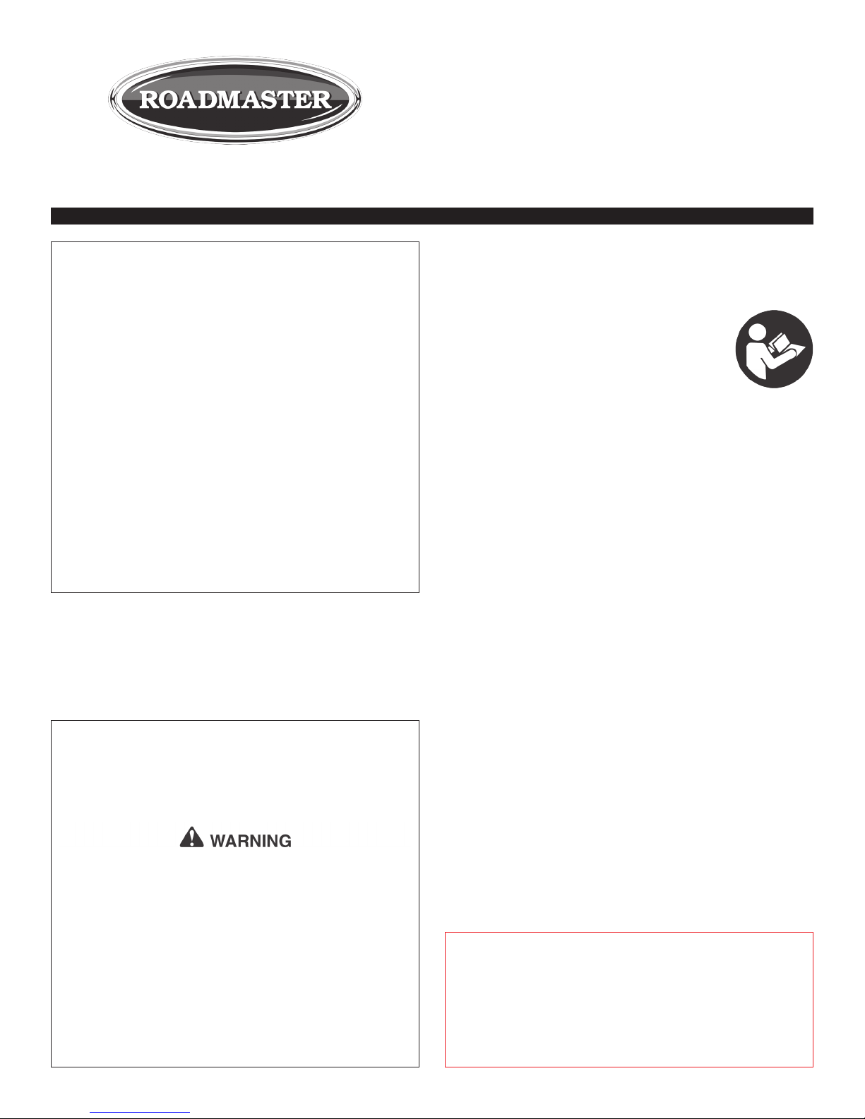
• You will remove the mounting nut (Figure 1) and the wiring
connectors (Figure 1) to install the switch. You must be able to
reach behind the switch to reattach them.
8. Using a power drill with a ¾-inch bit or a ¾-inch flat auger
bit, drill a hole at the mounting location you have chosen.
9. Remove the two wires from the switch by pulling on the
connectors until they separate from their terminals.
Note: if the connectors are difficult to remove from the
terminals, move them back and forth against the terminals as
you pull out.
10. Remove the mounting nut.
11. Position the switch in the hole, with the white dot side
(Figure 1) up.
12. Reattach the mounting nut, with the serrated side toward
Figure 1
the switch, and hand-tighten it.
13. Reattach the wire connectors into their terminals on the
switch.
14. Where possible, slide the black split loom over the wiring
connections and secure the loom with electrical tape.
15. Tape the wiring if there is any exposed metal in the immediate area of the switch.
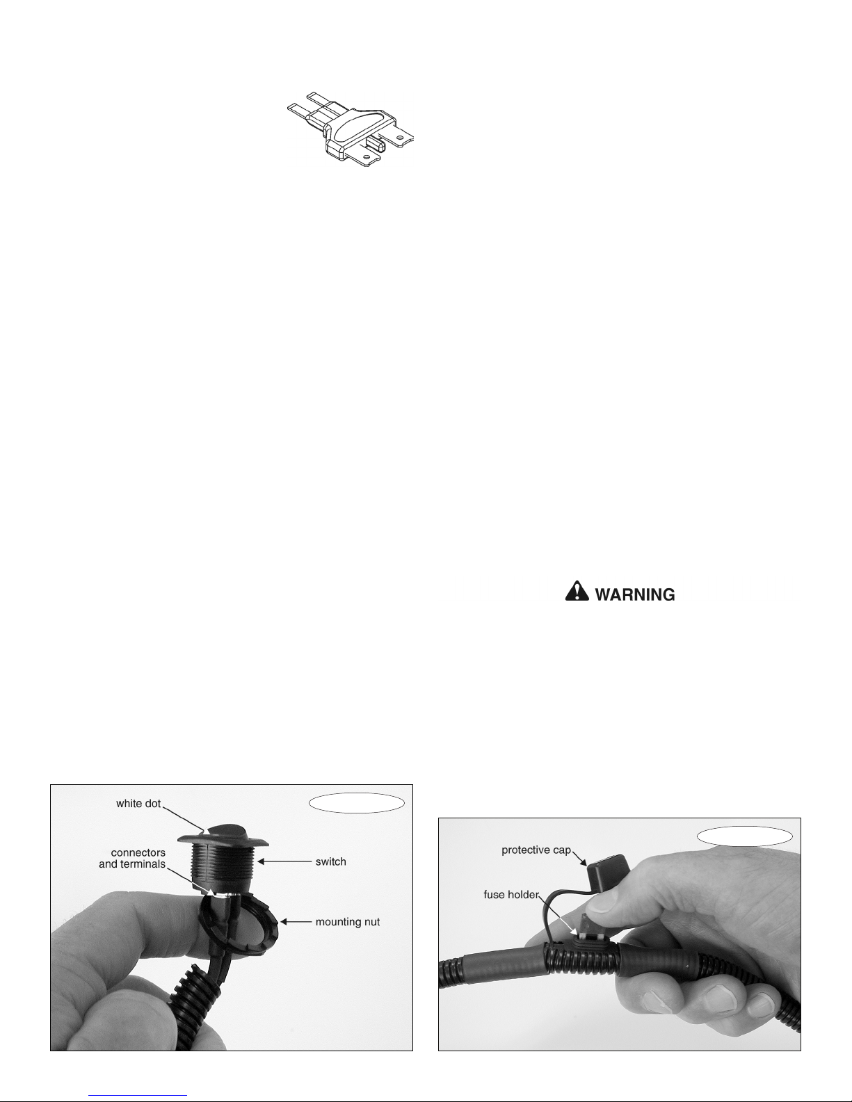
16. IMPORTANT — Install the fuse you removed from the towed
vehicle into the FuseMaster holder (Figure 2); confirm that the
fuse is fully seated. Replace the protective cap (Figure 2).
Note: if the fuse you removed was an ATM micro fuse,
install an ATM mini fuse (not included) of the same amperage.
CAUTION
ALWAYS match the amperage of the fuse in the FuseMaster harness to the fuse removed from the towed vehicle’s fuse panel. NEVER install a fuse with more than
a 20-amp rating into the FuseMaster harness.
Failure to follow these instructions may cause severe
damage to the vehicle’s electrical components. Other
consequential, non-warranty damage may also occur.
17. If desired, mount the included ‘Tow’ sticker under the switch
assembly and the ‘Drive’ sticker above the switch assembly.
Operating instructions
To drive the vehicle — flip the switch so that the side with
the white dot (Figure 1) is depressed.
To tow the vehicle — flip the switch so that the side with the
white dot is not depressed.
Never flip the switch to the “tow” position while driving.
If the switch is flipped, the electrical functions of the switch
FuseMaster has replaced will be lost.
A loss of power steering, power brakes and/or a loss of
vehicular control may result.
Failure to follow these instructions may cause property
damage, personal injury or even death.
Troubleshooting
If FuseMaster fails to operate as described, confirm that…
continued on next page
Figure 2
Page 3

continued from preceding page
• …the pins are fully seated in the fuse socket and not touching each other;
• …the wiring is properly connected to the back of the switch;
• …there is a properly-installed fuse in the FuseMaster harness and that it is not blown; and
• …the fuse socket adaptor (if used) is seated in the socket
and the spade connectors are properly attached.
Engine
compartment installation
If the fuse to be removed is located in the engine compartment, you will drill the access hole in the fuse box cover. Depending on the particular vehicle, you may drill the access
hole directly over the fuse or at a top side corner.
With this exception, follow the instructions above.
 Loading...