

Page 1

BrakeMaster 9100 and 9160
for motorhomes with air or air over hydraulic brakes
Installation Instructions
ROADMASTER, Inc. • 6110 NE 127th Ave. • Vancouver, WA 98682 • 800-669-9690 • fax 360-735-9300 • roadmasterinc.com
Towing and Suspension Solutions
Page 2
WELCOME TO THE ROADMASTER FAMILY!
hese instructions have been prepared to acquaint you with the installation of your BrakeMaster, and to
T
provide you with important safety information. Read these instructions, as well as the owner’s manual and all
accompanying literature, completely. Understand how to install and operate your BrakeMaster, and carefully follow
the instructions and safety precautions.
Your BrakeMaster has a one-year limited warranty. To qualify for your warranty, fill out and return the enclosed
product registration card within 30 days of purchase.
We thank you for your patronage and greatly appreciate your discerning taste.
TABLE OF CONTENTS
Safety definitions ..............................inside front cover
Before you begin the installation
(installer’s checklist) .............................................. 1
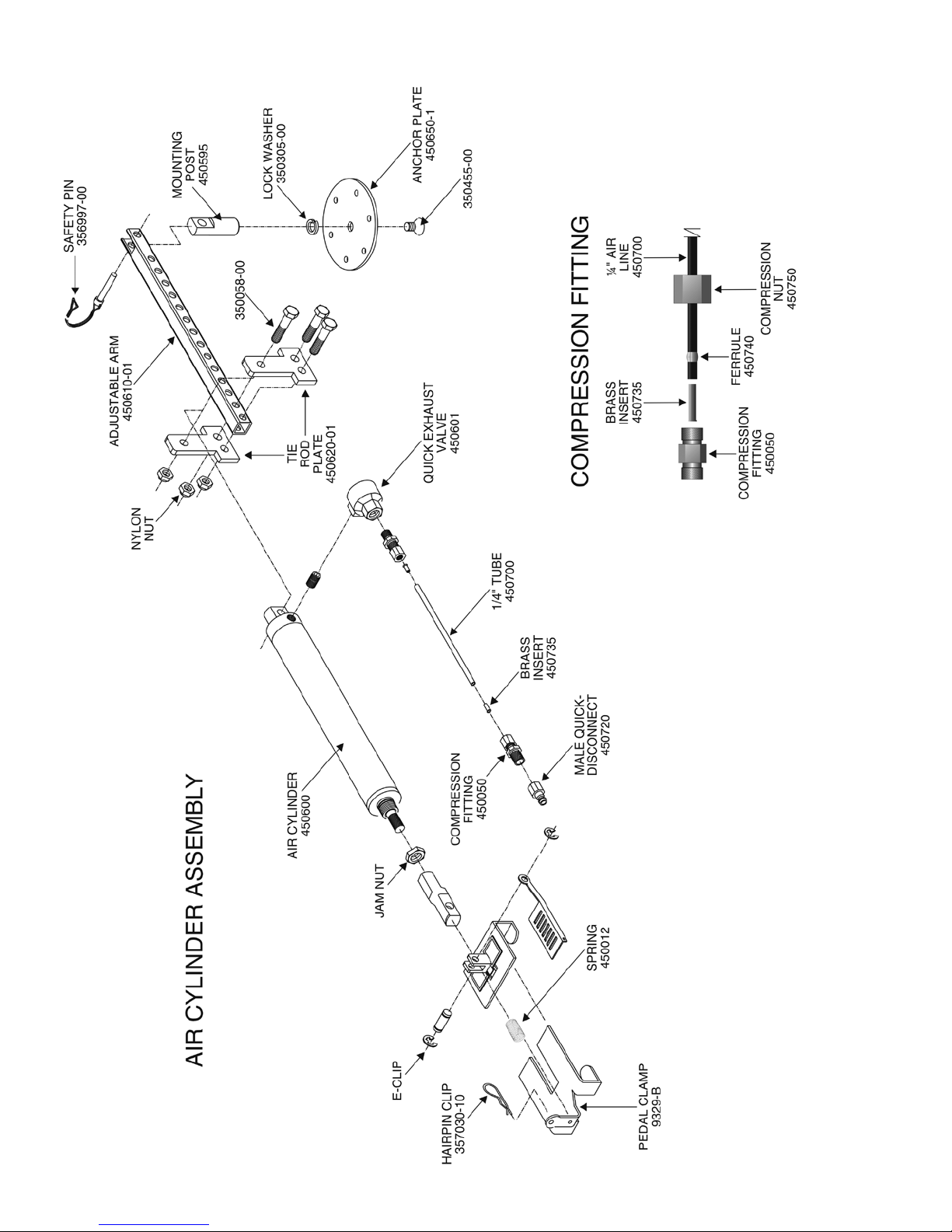
Air cylinder assembly and
compression fitting parts ....................................... 2
Install the air cylinder anchor plate ........................ 3-5
Install the break away system ................................ 6-7
Install air lines in the towed vehicle .......................8-9
Install the motorhome monitor system ................ 10-11
Install the motorhome air line ............................. 12-13
System test ......................................................... 14-15
Brake light solutions ................................................ 16
Ford ‘neutral tow’ vehicles .................................. 17-18
Troubleshooting ....................................................... 19
Vehicle-specific components .................................... 20
Index ........................................................................ 21
IMPORTANT NOTICE!
Safety Definitions
Statements in these instructions identified as follows are of special significance:
WARNING indicates a potentially hazardous situation which, if not avoided, could result in property
damage, serious personal injury, or even death.
Red type is used to emphasize warnings of particular significance.
CAUTION indicates a potentially hazardous situation which, if not avoided, may result in property
damage, or minor or moderate personal injury.
Red type is used to emphasize cautions of particular significance.
CAUTION used without the safety alert symbol
indicates a potentially hazardous situation which,
if not avoided, may result in property damage.
Red type is used to emphasize cautions of particular significance.
NOTE
Refers to important information and is placed in italic
type. It is recommended that you take special notice of
these items.
Page 3

BEFORE YOU BEGIN THE INSTALLATION…
fore it can be towed — verify that removing the fuse(s)
will not disrupt power to BrakeMaster, or otherwise af-
These instructions pertain to the initial installation only. Operating instructions are contained in
the owner’s manual.
Read all instructions before installing or operating the BrakeMaster system. Failure to understand
how to install or operate BrakeMaster could result in
property damage, personal injury or even death.
1. ALWAYS CHECK THE ROADMASTER WEBSITE —
www.roadmasterinc.com — for vehicle-specific information. Select ‘Vehicle-Specific Info,’ enter the motorhome
and towed vehicle make, model and year, then select
‘Braking Systems’ and scroll down the page.
2. If the battery must be disconnected for towing,
a stop light switch must be installed. ROADMASTER
manufactures stop light switch kits for a number of vehicles; to see if one is available for any specific vehicle,
visit www.roadmasterinc.com and select ‘Vehicle-Specific Info,' enter the vehicle make, model and year, then
select ‘Braking Systems' and scroll down the page.
Note: if a stop light switch kit is listed on the website
for any particular vehicle, it is required.
Note: an Automatic Battery Disconnect (part number
765) is available for vehicles which must be towed with
the battery disconnected. If you choose to install the
Automatic Battery Disconnect, a stop light switch is still
required; the Brake-Lite Relay is not required.
3. If the vehicle to be towed has an ‘active’ (or,
‘continuous power assist’) braking system, or if the
vehicle is not equipped with power brakes — order
the optional Brake Pressure Reducer (part number
900002) to adapt the vehicle to the BrakeMaster system.
Vehicles with ‘active’ brake systems include several
hybrid vehicles, such as some models of the Ford Escape hybrid and the Mercury Mariner hybrid, as well
as the H3 Hummer. These vehicles, and others with
these systems, are designed so that even when the
vehicle is set to ‘tow’ mode, the braking system is still
active, thus requiring minimal pressure to engage the
brakes.
If the vehicle to be towed has an ‘active’ braking system, or if the vehicle is not equipped with
power brakes, install the optional Brake Pressure
Reducer.
If the reducer is not installed, BrakeMaster will
apply excessive force to the towed vehicle’s brake
pedal, causing severe tire and/or brake system damage, as well as other, consequential damage.
fect the installation or operation.
5. Optional seat adaptor brackets are required for
some towed vehicles and simplify the installation for
others. Determine if a seat adaptor bracket is required,
or if one is available, for the towed vehicle — visit
www.roadmasterinc.com and select ‘Vehicle-Specific
Info,' enter the vehicle make, model and year, then
select ‘Braking Systems' and scroll down the page.
6. Test-fit the brake pedal clamp — although the
pedal clamp fits the vast majority of vehicles, in rare
circumstances, it may require additional adjustment. If
the pedal clamp does not attach to the brake pedal as
described on page 3, call the ROADMASTER Technical
Service Department at 800-669-9690.
7. Check the towed vehicle’s brake lights — Brake-
Master must function when all adjustments have been
made to prepare the vehicle for towing. These adjustments may include: turning the ignition key to the “tow”
position; pulling fuses; disconnecting the battery; and
setting the transmission to a particular gear or in a
particular sequence.
However, some vehicles’ brake lights will not operate
when these adjustments have been made.
Check to see if this is the case: after all adjustments
have been made, apply the brakes, and check to see
if the brake lights illuminate. If the brake lights do not
illuminate, a two-prong stop light switch and 10-amp
fuse must be installed.
ROADMASTER manufactures stop light switch kits
for a number of vehicles; to see if one is available for
any specific vehicle, visit www.roadmasterinc.com.
Note: check the owner’s manual to see if the vehicle
is equipped with an “automatic shut down” feature. If
this is the case, ensure that the vehicle is not in automatic shut down mode before performing this test.
Note: if you must install a Brake-Lite Relay — see
step 8, below — a stop light switch is not required.
8. An optional Brake-Lite Relay may be required.
Refer to “Brake light solutions” for instructions on how
to determine if the relay must be installed.
Note: a stop light switch (see steps 2 and 7 above)
and a Brake-Lite Relay are mutually exclusive — if you
use one, the other is not necessary.
9. An optional tee may be required to connect the
BrakeMaster air line to the motorhome brake relay valve
or air booster housing. Refer to “Install the motorhome
air line.”
These tees are available in two sizes: ½" (part number 450076) and 3/8" (part number 450077).
10. If the motorhome is equipped with air over hydraulic brakes — an additional amount of air line (part
number 450700) may be required.
4. If fuse(s) must be removed from the vehicle be-
1
Page 4
2
Page 5
INSTALL THE AIR CYLINDER ANCHOR PLATE
To determine where the anchor plate will be installed,
first attach the pedal clamp to the brake pedal. Follow
steps one through six below…
1. At the towed vehicle, slide the driver’s seat back,
as far as it will go.
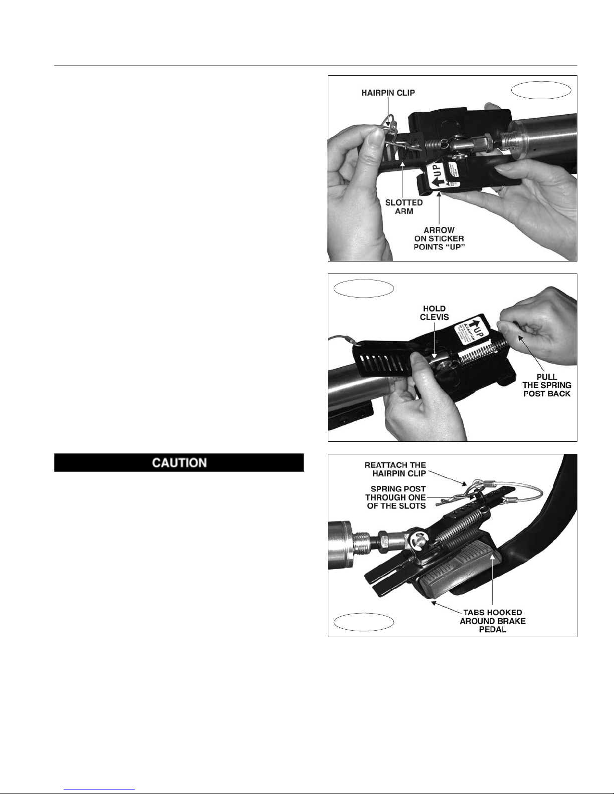
2. Verify that the pedal clamp is right side up, as shown
in Figure 1 — the arrow on the sticker will point “Up”
when the pedal clamp is properly positioned.
3. Pull the hairpin clip (Figure 1) out, then lift the slot-
ted arm (Figure 1) up and out of the way.
4. Move the pedal clamp over the brake pedal. Then,
hold the clevis (Figure 2) and pull back on the spring
post (Figure 2), until the tabs under the pedal clamp
are wide enough to clear the brake pedal.
5. Fit the pedal clamp onto the brake pedal, so that
all four tabs are hooked around it (Figure 3). Then,
release the spring post.
Note: on the initial installation, it may be necessary
to adjust the tabs on the pedal clamp — use pliers to
bend any or all of the tabs so that they hook around
and under the towed vehicle’s brake pedal.
Once the tabs have been adjusted to a specific
brake pedal, no further adjustment to the pedal clamp
is necessary for that vehicle.
If BrakeMaster is switched between towed vehicles,
always check the pedal clamp on the initial installation.
Verify that all four tabs are hooked around and under
the brake pedal. If necessary, bend the tabs to fit, as
described above.
Figure 2
Figure 1
Make certain that all four tabs on the pedal clamp
are securely hooked around the brake pedal (Figure
3). If the tabs are loose when the vehicle is towed,
the pedal clamp can rotate out of position and hold
the brake pedal down, even when BrakeMaster is
not activated, which will cause tire and/or brake
damage, or other consequential, non-warranty damage.
6. Swing the slotted arm back over the spring post, fit
the spring post through one of the slots, and reattach
the hairpin clip (Figure 3).
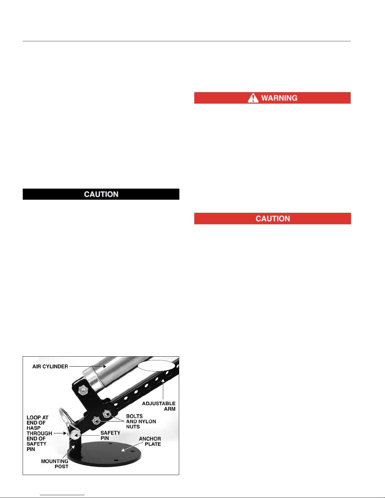
7. Now that the pedal clamp is in place, attach the
anchor plate (Figure 4) —
Note: optional seat adaptor brackets are required
for some towed vehicles and simplify the installation
for others. Before attaching the anchor plate, determine if a seat adaptor bracket is required — visit
www.roadmasterinc.com. Select ‘Vehicle-specific Info,'
enter the vehicle make, model and year, then select
‘Braking Systems’ and scroll down the page.
Choose a mounting point under the driver’s seat as
Figure 3
far back as possible — ideally, the anchor plate should
be concealed when the driver's seat is moved forward,
and visible only when the driver's seat has been moved
back as far as it will go.
BrakeMaster is shipped with the air cylinder at the
shortest position. If necessary, lengthen the reach of
the air cylinder, to position the anchor plate at the point
you have chosen — remove the two bolts and nylon nuts
continued on next page
3
Page 6
INSTALL THE AIR CYLINDER ANCHOR PLATE
continued from preceding page
(Figure 4) attaching the cylinder to the adjustable arm
(Figure 4). Slide the air cylinder (Figure 4) up the adjustable arm until the anchor plate is over the point you
have chosen. Replace the two bolts and nylon nuts.
Note: if BrakeMaster is switched between towed
vehicles, it may be necessary to lengthen or shorten
the reach of the air cylinder, as described above.
Note: if the vehicle is equipped with an automatic
pedal positioning system, adjust the brake pedal to its
farthest extension (as close as possible to the driver’s
seat) before positioning the air cylinder and the mounting post. This will eliminate the possibility of positioning
the anchor plate too close to the brake pedal.
8. Next, if necessary, move the air cylinder to the left
or the right, until the mounting post (Figure 4) is directly
in line with the brake pedal.
The air cylinder must be mounted directly in line
with the brake pedal. If it is mounted at an angle
to the brake pedal (to one side or the other), the
air cylinder may jam in the extended position when
BrakeMaster is activated, which will cause severe
brake system damage, as well as other consequential, non-warranty damage.
Note: the anchor plate can be rotated clockwise or
counterclockwise, if necessary, to clear any obstructions
— to rotate the anchor plate, remove the air cylinder
and lock the plate in a vise. Use a half-inch open-end
wrench to loosen the mounting post, while holding the
retaining screw (at the bottom of the plate) with an Allen
wrench. Do not turn the retaining screw with the Allen
wrench, as you may damage the wrench or the screw.
When the mounting post is loose, rotate the anchor
plate. Then, tighten the mounting post.
9. Before attaching the anchor plate, verify that the
Figure 4
following conditions are met:
A. Make certain that the pedal clamp is not de-
pressing the towed vehicle’s brake pedal — examine the
brake pedal, and also check the towed vehicle’s brake
lights, to make certain they are not illuminated.
Make certain that the pedal clamp is not depress-
ing the towed vehicle’s brake pedal.
If the pedal clamp is pushing the brake pedal
down, the brakes will be applied continuously when
BrakeMaster is connected, which will cause severe
tire and/or brake system damage, as well as other
consequential, non-warranty damage.
Failure to follow these instructions may cause
property damage, personal injury or even death.
B. When it is connected, the air cylinder must be
pulled back toward the anchor plate in order to insert
the safety pin (Figure 4) through the mounting post.
The air cylinder must be pulled back when it is
connected, in order to create sufficient spring tension to keep the weight of the cylinder off the brake
pedal. If the cylinder is not pulled back when it is
connected, the weight of the cylinder may cause
the pedal clamp to depress the towed vehicle’s
brakes continuously, which will cause excessive
brake wear, brake system damage, or other consequential, non-warranty damage.
C. The pedal clamp must be flat against the brake
pedal and properly secured with the hairpin clip (Figure
3).
D. Make certain that there is sufficient clearance
between the mounting post and the bottom of the seat
to allow the seat to slide properly.
10. Once the four conditions in step 9 (above) are met,
attach the anchor plate. (It may be helpful to remove the
driver’s seat to facilitate the rest of the installation.)
The anchor plate can be attached on top of the
carpet, or underneath it.
A. To mount the plate on top of the carpet, first
use the anchor plate as a template and mark the five
holes to be drilled.
Before drilling, make certain that the retaining screw
(at the bottom of the mounting post) is fully tightened.
(To tighten the screw, reverse the instructions in step 8,
above.) Also, make certain that you will not drill through
any wiring or electrical components underneath the
carpeting, or damage any components on the other
continued on next page
4
Page 7
INSTALL THE AIR CYLINDER ANCHOR PLATE
continued from preceding page
side of the floorboard.
Do not drill through any wiring. The air bag sensor wire may be located under the driver’s seat.
Drilling into this wire may disable the air bag system, or may cause the air bags to deploy immediately, which may cause severe personal injury.
Failure to follow these instructions may cause
property damage, personal injury or even death.
Next, drill five ¼" holes at the points you marked.
Drill through the carpet and the floorboard. Use caution
to prevent the drill bit from catching on threads in the
carpet and unraveling it.
B. If mounting the anchor plate underneath the
carpet, cut a small flap in the carpet to allow the mount-
ing post to protrude through it.
As described above, use the anchor plate as a template, and drill five ¼" holes through the floorboard.
Figure 5
STANDARD
INSTALLATION
DRILL 1/4" HOLE
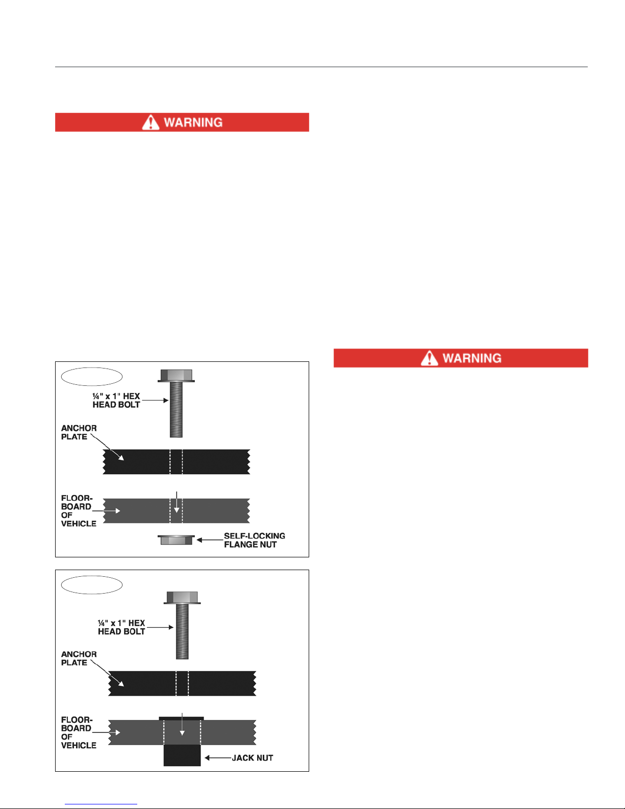
11. Next, attach the anchor plate as shown in Figure
5, using the provided ¼" x 1" hex head bolts and selflocking flange nuts.
12. If you find that tightening the flange nut on a bolt
is difficult due to a tube, channel or other obstruction
under the floorboard, use one of the provided jack nuts
to attach the bolt. Refer to Figure 6.
Note: if one or more jack nuts are used, the anchor
plate cannot be mounted on top of the carpet.
To attach a bolt with a jack nut, drill a ½" hole
through the floorboard at the point you marked in step
10.
Note: do not drill out the hole in the anchor plate.
Next, insert the jack nut into the hole (See Figure
6) and bolt through the anchor plate, using one of the
¼" x 1" hex head bolts.
13. This completes the anchor plate installation. You can
leave the air cylinder assembly in place — it must be
attached to install an air line fitting in a later step — or
you can remove it, if it interferes with the installation.
Automatic pedal positioning systems may affect
the towed vehicle braking system.
Determine if the vehicle to be towed is equipped
with pedal presets. Proper connection of the braking system may be affected by these presets; if the
vehicle is so equipped, note the original installed
position and return to that position before towing
the vehicle.
If the brake pedal is not at the original installed
position when the vehicle is towed, the pedal clamp
may apply excessive braking force, which will damage the brake system and/or electrical system, and
may cause brake or electrical system failure, as well
as other non-warranty damage.
Failure to follow these instructions may cause
property damage, personal injury or even death.
Figure 6
DRILL 1/2" HOLE
JACK NUT
INSTALLATION
NOTE: DO NOT
DRILL OUT THE
HOLE IN THE AN-
CHOR PLATE!
5
Page 8
INSTALL THE BREAK AWAY SYSTEM
Note: the BrakeAway™ system is included with the
9160; it is an optional accessory for the 9100.
Step One
Install the air reservoir
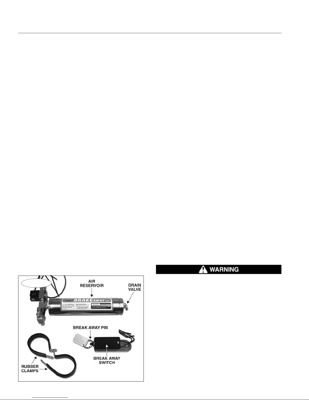
1. First, choose a location for the air reservoir (Figure
7). The air reservoir is mounted in the towed vehicle,
most often in the engine compartment, but it may be
attached anywhere an air line can be routed from the
top of the air reservoir to the front of the vehicle, and
where the drain valve (Figure 7), at the bottom of the
reservoir, is easily accessible.
Choose a location that meets the following conditions:
• An air line will be attached to the reservoir in a later
step. One end will be routed to the driver’s side of the
passenger compartment; the other end will be routed
to the front of the vehicle. This air line cannot be closer
than two feet from any heat source, such as the engine
or exhaust system, which might damage the air line.
• The air reservoir must be mounted away from any
moving parts, so that the air reservoir will not be damaged by, or interfere with, the proper operation of any
components.
• Choose a location that will allow the bottom of the
air reservoir to be mounted lower than the top, so that
any accumulated water can be drained from the tank.
The reservoir cylinder does not have to be perfectly
straight up and down, but the drain valve must be the
lowest part of the reservoir.
• The reservoir will be attached with two of the sup-
plied ¼" x 1" hex bolts and nuts. Choose a location
that will allow you sufficient access to tighten the hex
nuts from the other side.
Note: because the air reservoir will be charged with
compressed air, it cannot be mounted inside the pas-
senger compartment of the vehicle.
2. Once you have chosen a location for the air res-
ervoir, fold the two rubber clamps (Figure 7) over the
cylinder. Press the ends of each clamp together, until
the pre-drilled holes align.
Test-fit the reservoir and slide the clamps up or down
the cylinder, if necessary, until the pre-drilled holes are
both over a surface where the hex bolts and nuts will
hold each clamp in place. Mark the center of each hole
for drilling, and set the reservoir aside.
Before drilling, make certain you will not damage
any components on the other side. Then, drill a ¼"
hole through the two points you have marked.
Before attaching the clamps, rotate the top of the
reservoir so that the two wires at the solenoid valve
(Figure 10), as well as the two brass air compression
fittings (Figure 10), will be easily accessible.
Position the reservoir and clamps over the two holes,
and secure the reservoir in place with one of the ¼" x
1" hex bolts and nuts at each clamp.
Step Two
Mount the break away switch
1. Mount the break away switch (Figure 7) at the front
of the vehicle, on the driver’s side. Choose an area you
can easily reach, with a surface of sufficient strength to
hold the switch firmly in place, so that the break away
pin (Figure 7) will pull freely from the switch. Mount the
switch in a horizontal position, with the break away pin
facing toward the motorhome.
Ensure that the break away pin can be pulled freely away from the towed vehicle, without any obstructions.
Figure 7
6
Do not attach the break away switch to the tow
bar or the tow bar bracket. If the tow bar or bracket
fails, the break away switch will separate with it,
preventing the break away system from activating.
If the towed vehicle separates, the brakes will not
be applied, which may cause property damage, personal injury or even death.
Step Three
Connect the wiring
Note: if the vehicle’s battery must be disconnected
for towing and an automatic battery disconnect has
been installed, additional modifications are necessary. If
a ROADMASTER Dinghy Battery Manager (part number
continued on next page
Page 9

INSTALL THE BREAK AWAY SYSTEM
Connect the wiring
continued from preceding page
765) has been installed, follow the instructions included
with the kit.
1. Using one of the blue butt connectors, attach one
end of the supplied length of 14-gauge black wire to
the end of either one of the two wires extending from
the break away switch. (If necessary, strip ¼" to 3/8" of
insulation from the end of the wires before connecting
them.)
Next, route the wire to the positive terminal on the
towed vehicle’s battery (Figure 8), avoiding moving
parts, sharp edges or “hot” components such as the
engine or exhaust system. Where appropriate, use one
or more of the included wire ties to secure the wire in
place.
2. Cut the wire and strip ¼" to 3/8" of insulation from
the end of the wire. Crimp either end of the supplied
yellow 10-amp fuse onto the end of the wire. Strip the
insulation from one end of the remaining length of wire;
crimp the other end of the fuse onto the wire.
3. If necessary, cut the wire again, leaving no more
than six inches, and strip ¼" to 3/8" of insulation from
the end of the wire. Crimp the larger (3/8") ring terminal
onto the end of the wire, and attach the ring terminal to
the positive terminal on the towed vehicle’s battery.
the 10-amp fuse must be within six inches of the
positive terminal. If the 10-amp fuse is farther than
six inches, a short circuit may cause significant
damage to the towed vehicle’s electrical system, an
electrical fire, or other consequential, non-warranty
damage.
4. Now, connect the remaining wire at the break away
switch to either one of the two wires extending from the
top of the solenoid valve on the air reservoir (Figures
8 and 10). If necessary, use the remaining length of
14-gauge black wire to reach the top of the solenoid
valve. As before, strip the ends of the wires before connecting them with the supplied blue butt connectors.
Where appropriate, use one or more of the included
wire ties to secure the wire in place.
5. Crimp the smaller (#10) ring terminal onto the end
of the remaining wire extending from the top of the
solenoid valve, and attach the ring terminal to any good
chassis ground. (If necessary, use another butt connector, and any remaining 14-gauge black wire, to extend
the length of the ground wire.)
6. If the battery must be disconnected for towing, install
a battery switch to the positive battery cable, as shown
in Figure 9. Connect the stop light switch wiring to the
battery switch.
In order to prevent damage from a short circuit,
Figure 8
Figure 9
7
Page 10

INSTALL AIR LINES IN THE TOWED VEHICLE
1. Find a suitable location at the front of the towed
vehicle to attach the preassembled male quick coupler
(Figure 10). Choose an area within easy reach, with
a surface of sufficient strength to hold the mounting
bracket firmly in place.
Do not attach a female quick coupler at the front
of the towed vehicle. The female quick couplers
have an internal check valve to prevent air from
escaping. If air pressure is not released, the BrakeMaster pedal clamp will not retract when the system
is activated, which will cause severe brake system
damage, or a brake fire, as well as other consequential, non-warranty damage.
Failure to follow these instructions may cause
property damage, personal injury or even death.
2. Attach the bracket with two of the supplied ¼" nuts
and bolts, with the male quick coupler pointing away
from the towed vehicle.
Note: the weather covers will prevent dirt or debris
from entering the lines. Keep the fittings covered when
the braking system is not in use.
3. Connect one end of the air line to the male quick
coupler compression fitting (Figure 10) — first, if necessary, trim the end of the air line, to make a smooth and
straight cut. Then slide the compression nut and the
ferrule (Figure 10) over the air line. Position the ferrule
¼" from the end of the air line.
Next, slide one of the brass inserts (Figure 10) into
the end of the line.
Note: if the brass inserts are omitted, the fittings will
not be airtight.
Now, push the air line into the compression fitting,
as far as it can go. Then push the ferrule into the compression fitting, and tighten the compression nut onto
the fitting.
Note: if the compression nut is overtightened, the fitting will not be airtight. After completing the installation,
check all the fittings for air leaks — see “System test.”
4. Tape the open end of the air line. Then, route the air
line from the male quick coupler to the break away air
reservoir, avoiding moving parts, sharp edges or “hot”
components such as the engine or the exhaust system.
Do not kink the air line, or bend it to the extent that it
crimps or creases.
Note: if the break away system was not installed,
route the air line through the engine compartment and
through the firewall — see step 7 below.
Do not position the air line closer than two feet
from any heat source. The heat will soften the plastic, which will cause the air line to rupture.
If the air line is ruptured, the supplemental braking system will not function.
Do not kink the air line, or bend it to the extent
that it crimps or creases — air pressure will be substantially reduced, or blocked entirely, at the kink
in the line.
If the air pressure is reduced, the supplemental
braking system will not function, or may only function intermittently.
Where appropriate, use wire ties to secure the air
line in place.
5. At the top of the break away air reservoir (Figure
11), cut the air line to length and attach the open end
to the brass “air in” compression fitting (Figure 11). Use
the same method described in step 3 (above) to attach
the air line.
6. Next, attach the end of another section of air line
to the brass “air out” compression fitting on the top of
the break away air reservoir (Figure 11 ). Use the same
method described in step 3 (above) to attach the air
line.
7. Tape the open end of the air line. Then, route the
air line from the break away air reservoir through the
engine compartment and to the driver’s side of the firewall. As before, avoid moving parts, sharp edges or
continued on next page
Figure 10
8
Figure 11
Page 11

INSTALL AIR LINES IN THE TOWED VEHICLE
continued from preceding page
“hot” components such as the engine or the exhaust
system. Do not kink the air line, or bend it to the extent
that it crimps or creases.
Where appropriate, use wire ties to secure the air
line in place.
8. Next, look for a pre-existing hole in the firewall (or,
if there is sufficient space, a pre-existing wiring grommet) on the driver’s side, to route the air line through
the firewall.
If there is no pre-existing hole or grommet with sufficient space, drill a ½" hole through the firewall.
Drill from the engine compartment or from the interior of the vehicle, whichever is more convenient.
Before drilling, make certain you will not damage any
components on the other side of the firewall.
9. Fit the included firewall grommet into the ½" hole,
and push the end of the air line through.
10. The air line will be connected to the preassembled
female quick coupler without the orange shield base
(Figure 12).
Find a likely mounting point for the bracket on the
driver’s side — choose an area within easy reach, with
a surface of sufficient strength to hold the mounting
bracket firmly in place.
The bracket and quick coupler must not present
an obstacle or hazard to the driver of the vehicle, or
otherwise interfere with the operation of the vehicle.
Two common mounting points are: 1) under the
dashboard, on the kick panel; or 2) far enough under
the front of the driver’s seat so that the quick coupler
is accessible when the seat is slid back, but concealed
when the seat is slid forward.
Or, depending on the interior design of the vehicle,
there may be a more suitable mounting point.
Before attaching the bracket, first connect the
BrakeMaster air cylinder assembly. Make certain that
the male quick coupler at the end of the air line will
reach the point you have chosen to attach the female
quick coupler, without kinking either of the air lines.
Note: the quick exhaust valve on the air cylinder
(see page 2) may be rotated, if this provides an easier
connection.
Before attaching the coupler, make certain you will
not damage any components on the other side.
If you have chosen to attach the bracket under the
driver’s seat, make certain that the female quick coupler
and bracket will not interfere with the normal movement
of the driver’s seat, or affect any adjustments to the
driver’s seat.
• If you have chosen to attach the bracket to the kick
panel, attach it with two of the supplied ¼" nuts and
bolts, with the female quick coupler pointing toward the
rear of the towed vehicle.
• If you have chosen to attach the bracket under the
driver’s seat, route the air line from the firewall to the
front edge of the driver’s seat. Remove the rocker panel
or side trim (or, detach the carpeting) and conceal the
air line underneath it.
Move the driver’s seat back, as far as it will go.
Attach the bracket with two of the supplied ¼" nuts
and bolts, with the female quick coupler pointing toward
the front of the vehicle.
11. Cut the air line to length and attach it to the com-
pression fitting on the female quick coupler. Use the
same method described in step 3 (above) to attach the
air line.
12. Seal the firewall grommet with a silicone sealant.
Reattach the rocker panel (or side trim or carpeting),
if it was removed.
13. Find a suitable location at the rear of the motorhome,
near the center, to attach the remaining preassembled
female quick coupler (with the orange shield base —
Figure 13). Attach the bracket with two of the supplied
¼" nuts and bolts, with the female quick coupler pointing away from the motorhome.
Note: the weather covers will prevent dirt or debris
from entering the lines. Keep the fittings covered when
the braking system is not in use.
TOWED VEHICLE MOTORHOME
Figure 12
Figure 13
9
Page 12

INSTALL THE MOTORHOME MONITOR SYSTEM
Step One
Wire the towed vehicle
Note: there are two lengths of black wire in this kit,
each with a female bullet connector at one end. Use
the short length of wire in this step.
1. Choose a mounting point at the front of the vehicle,
near the male quick coupler you attached in step 2,
“Install air lines in the towed vehicle,” for the end of
the harness with the female bullet connector. Attach the
connector with one or more of the included wire ties.
Allow enough slack so that a male bullet connector can
be plugged into and out of it.
2. Once the female bullet connector is attached, route
the monitor wiring harness through the engine compartment, to the driver’s side of the firewall. Use the same
route as the air line, if that is convenient. As before,
avoid lines, hoses, moving parts or “hot” components
such as the engine or exhaust systems. Where appropriate, use wire ties to secure the wiring harness
in place.
3. Route the monitor wiring harness through the same
hole as the air line.
4. Before connecting the monitor wiring harness to the
brake light wire, determine if the optional Brake-Lite
Relay must be installed — refer to “Brake light solutions,”
in these instructions, for information on how to identify
the type of brake and turn signals in the vehicle. Then,
test the towed vehicle’s brake lights, as described in
“Brake light solutions.”
Several wiring alternatives are available to you,
based on the type of brake and turn signals in the
vehicle, and the results of the test.
5. Next, locate the towed vehicle’s brake light switch
and, with a test light, find the “cold” side of the brake
light switch. (The “cold” side of the switch does not
register voltage unless the brakes are applied.) With a
12-volt meter, verify that you have found 12 VDC+.
Then, remove the vehicle’s brake light fuse, located in
the vehicle’s fuse panel.
Failure to remove the brake light fuse from the
vehicle’s fuse panel may cause the vehicle’s theft
deterrent system, or other electrical system indicators, to be activated if the brake pedal is depressed
during the installation. This may require non-warranty repair to the vehicle.
6. Cut the brake light wire, a few inches downstream
from the “cold” side of the brake light switch.
If the Brake-Lite Relay is required…
(see step 4, above)
Install the Brake-Lite Relay now. The instructions
are included with the kit. After the Brake-Lite Relay is
installed, proceed to Step Two, “Wire the motorhome”
(below).
If the Brake-Lite Relay is not required…
(see step 4, above)
7. If necessary, trim the monitor wiring harness, then
attach the monitor wire to the brake light wire, using
the supplied yellow butt connector.
8. Ensure that the monitor wiring harness will not pres-
ent an obstacle or hazard to the driver of the vehicle,
or interfere with the operation of the vehicle. Use one
or more wire ties, if necessary, to secure the wiring
harness out of the way.
9. Reinstall the brake light fuse, which you removed
in step 5.
continued on next page
10
Figure 14
Page 13

INSTALL THE MOTORHOME MONITOR SYSTEM
continued from preceding page
Step Two
Wire the motorhome
Note: there are two lengths of black wire in this kit,
each with a female bullet connector at one end. Use
the long length of wire in this step.
Note: some motorhomes are manufactured with auxiliary wires pre-strung from the rear of the motorhome
to the dashboard, for aftermarket accessories such as
this. Call the manufacturer.
1. Attach the end of the black wire with the female bullet connector to the back of the motorhome, near the
female quick coupler you attached in step 13, “Install
air lines in the towed vehicle.”
Attach the connector with one or more of the included wire ties. Allow enough slack so that a male
bullet connector can be plugged into and out of it.
2. Once the female bullet connector is attached, route
the wire from the back of the motorhome to the underside of the dashboard. Avoid lines, hoses, moving parts
(slideouts, sliding generators, sliding battery trays) or
“hot” components such as exhaust systems. Where
appropriate, use wire ties to secure the wire to the
undercarriage.
Step Three
Attach the LED
1. Choose an area on the motorhome dashboard to
mount the LED. Look for a mounting point away from
pre-existing wires or components, where the LED can
be easily seen by the driver.
2. Drill a 5/16" hole through the dashboard at the point
you have chosen. Before drilling, make certain you will
not damage any components on the other side.
3. Center the LED decal (Figure 15) over the hole, and
press it down. Or, you may choose to omit the decal,
depending on your preferences.
4. From the top of the dashboard, slide the LED through
the hole, wires first, until the base of the bulb (Figure
15) is flush to the top of the dash.
5. From the underside of the dash, fit both of the wires
through the speed nut (Figure 15). Then push the speed
nut up, against the dash, to secure the LED in place.
6. Connect to power — Trim the black wire, which you
routed from the back of the motorhome. (Save the excess; you may use it in the next step.) Then, connect
the black wire to the red LED wire, using one of the
included butt connectors.
7. Connect to ground — Connect the ground wire from
the LED to any good chassis ground, using the included
Figure 15
ring terminal. (If necessary, use any excess wire from
the preceding step to extend the length of the ground
wire.)
Step Four
Connect the patch cord between
the motorhome and the towed vehicle
Note: the patch cord is the six-foot length of air line
and wiring, covered in blue plastic loom.
1. Connect the male and female quick couplers at
either end of the air line to the corresponding quick
couplers on the motorhome and towed vehicle.
Push the couplers together until the housing (Figures
12 and 13) on the female coupler slides forward and
‘clicks,’ locking the couplers together.
(To disconnect the couplers, pull back on the housing on the female coupler until the couplers release.)
Never pull back on the housing to connect the couplers — this will prevent the couplers from locking. The
couplers may disconnect during towing, preventing
the supplemental braking system from functioning.
2. Connect the male bullet connectors at either end
of the monitor wire to the female bullet connectors on
the motorhome and towed vehicle monitor wiring harnesses.
11
Page 14

INSTALL THE MOTORHOME AIR LINE
There are three possible connection points for the
motorhome air line —
• If the motorhome has air brakes, the line can be
attached to an open port at the air brake relay valve.
• If the motorhome has air over hydraulic brakes, the
line can be attached to an open port at the main brake
air booster housing.
• If there is no open port, a tee must be used.
In this step, you will attach the motorhome air line
at one of these three points, then route it to the rear
of the motorhome.
1. Support and block the motorhome. Then, release
the parking brake.
The motorhome must be safely and securely sup-
ported and blocked.
With the parking brake released, the motorhome
may unexpectedly roll forward or backward, especially if it is on an incline, if it is not blocked.
If the motorhome is equipped with an air suspension system and a line to the air suspension system
is inadvertently opened, or if the motorhome’s air
suspension system is turned off, the motorhome
will lower to the ground.
Failure to follow these instructions may cause
property damage, personal injury or even death.
The motorhome’s parking brake must be released,
in order to test and identify the correct port.
If an incorrect port is chosen, the motorhome
brake system will be severely damaged. A brake fire
or other non-warranty damage may also occur.
2. Start the motorhome engine and allow the air brake
system to completely charge up to operating pressure.
3. If the motorhome has air brakes — find the air
brake relay valve (Figure 16), which is typically located
near the master cylinder. There should be one or more
open ports with threaded plugs (Figure 16).
If the motorhome has air over hydraulic brakes —
find the main brake air booster housing (Figure 17), which
is typically located near the front axle. There should be
an open plug (Figure 17) threaded into the air booster
housing.
4. Test to verify that you have located the correct port
(an assistant will be necessary for this test, to press and
release the motorhome brake pedal)…
The air brake system contains pressurized air,
which may cause severe eye or ear injury when it is
released. Wear appropriate eye and ear protection
before loosening any plugs, and while attaching the
air line.
5. First, slowly loosen the plug — do not remove it en-
tirely. Then instruct the assistant to depress the motorhome brake pedal several times. Pressurized air should
escape from the port each time the brake pedal is depressed.
If pressurized air is only released when the brake
pedal is depressed, you have located a port to attach the
BrakeMaster air line.
6. Turn the motorhome engine off. Remove the original
fitting from the port, and thread the appropriate-sized
fitting (½" and 3/8" fittings are provided) into the port.
Use a liquid Teflon® sealant to seal the pipe threads
(Do not use liquid Teflon on any compression fittings).
Proceed to step 8 (below).
7. If an open port is not available — Not all relay
valves or air booster housings will have an empty port
available. If this is the case, the BrakeMaster air line
continued on next page
12
Figure 17
Figure 16
Page 15

INSTALL THE MOTORHOME AIR LINE
continued from preceding page
must be connected with a tee to the service port at the
relay valve or air booster housing.
ROADMASTER manufactures tees for this purpose (Figure 18), in ½" (part number 450076) and 3/8"
sizes (part number 450077). Matching compression fittings are provided in the BrakeMaster kit.
The correct port should be identified as the “service
brake” port. First, with the motorhome brakes released,
disconnect the factory air line from the service port —
push down on the locking collar and then pull out. (If
the ports are not identified, follow steps 4 and 5 above
to identify the service port.)
Next, remove the factory fitting from the service
brake port.
Clean the factory fitting. Apply a liquid Teflon sealant to the threads on the male fitting of the new tee,
and thread it into the port. Use either one of the two
female fittings on the new tee to reinstall the factory
fitting, and then the factory air line.
Use the compression fitting provided with the ROADMASTER tee to attach the BrakeMaster air line to the
remaining female fitting. Use the same method described in step 3 under “Install air lines in the towed
vehicle” to attach the air line.
Proceed to step 9 (below).
Where appropriate, use wire ties to secure the air
line in place.
10. Connect the air line to the female quick coupler
at the rear of the motorhome. Use the same method
described in step 3 under “Install air lines in the towed
vehicle.”
11. The BrakeMaster installation is complete. Before the
supplemental braking system is operated for towing,
proceed to the next section — “System test.”
To finish the installation…
8. Now that the fitting is in place, connect one end of
the remaining length of air line to the fitting. Use the same
method described in step 3 under “Install air lines in the
towed vehicle.”
9. Tape the open end of the remaining length of air
line. Then, route the air line from the relay valve (or air
booster housing) to the female quick coupler at the rear
of the motorhome. As before, avoid moving parts, sharp
edges or “hot” components such as the engine or the
exhaust system. Do not kink the air line, or bend it to the
extent that it crimps or creases.
Do not position the air line closer than two feet
from any heat source. The heat will soften the plasic, which will cause the air line to rupture.
If the air line is ruptured, the supplemental braking system will not function.
Do not kink the air line, or bend it to the extent
that it crimps or creases — air pressure will be substantially reduced, or blocked entirely, at the kink
in the line.
If the air pressure is reduced, the supplemental
braking system will not function, or may only function intermittently.
Figure 18
13
Page 16

SYSTEM TEST
Always deplete the stored vacuum in the towed
vehicle’s power brake system before towing — pump
the brake pedal several times.
Depending on the make and model of the towed
vehicle, it may be necessary to pump the brake
pedal repeatedly to deplete the vacuum.
If the vacuum is not released, the supplemental
braking system will apply excessive braking force
when it is activated, which will cause severe tire
and/or brake system damage to the towed vehicle.
1. The motorhome and towed vehicle must be station-
ary for the system test, and ready for towing…
• Connect and attach the tow bar to the motorhome
and towed vehicle.
• According to the manufacturer, make all adjustments
necessary to prepare the vehicle for towing. These adjustments may include: turning the ignition key to the
“tow” position; pulling fuses; disconnecting the battery;
and setting the transmission to a particular gear or in
a particular sequence.
To prevent the towed vehicle from rolling, connect and attach the tow bar to both vehicles before
shifting the towed vehicle’s transmission into the
proper gear for towing.
• Connect the patch cord between the two vehicles
— both the air line quick couplers and the motorhome
monitor bullet connectors — see Step Four, “Connect the
patch cord between the motorhome and the towed vehicle,” under “Install the motorhome monitor system.”
• Attach the air cylinder to the brake pedal and mount-
ing post (or seat bracket adaptor) — see “Install the air
cylinder anchor plate.” Connect the male quick coupler
at the end of the air line on the air cylinder to the female
quick coupler at the end of the air line mounted in the
passenger compartment.
• Clip one end of the steel break away cable to the
break away pin (Figure 7); clip the other end of the
cable to the rear of the motorhome, close to the center.
2. Block the motorhome’s wheels, then release the
parking brake. Turn the motorhome engine on, and
leave it running.
3. After the air brake system is completely charged,
check for leaks in the air system: Have an assistant
apply the motorhome brakes and continue to hold the
brake pedal down.
Cover each joint, fitting and connection in the air
system with a leak check solution.
The air system now contains pressurized air,
which may cause severe eye or ear injury if it is
inadvertently released. Wear appropriate eye and
ear protection before adjusting the air system connections and fittings.
Tighten any fittings, if necessary, and repeat until
all connections are airtight.
4. Confirm the proper operation of the braking system:
depress and hold the motorhome brake pedal down.
At the towed vehicle, the air cylinder shaft and pedal
clamp will extend. Then, release the brake pedal. The
air cylinder shaft and pedal clamp will retract.
5. Confirm that the motorhome monitor is function-
ing: the LED will illuminate after the motorhome brake
pedal is depressed, and stop when the brake pedal is
released.
If the LED does not turn on and off as described
above, identify and correct the cause before using the supplemental braking system. Refer to the
Troubleshooting section for possible causes.
The LED is the only indication of braking activity at the motorhome. Severe damage to the towed
vehicle, a loss of vehicular control, or other consequential, non-warranty damage can occur if the
driver of the motorhome is unaware that the supplemental braking system is not functioning properly.
Failure to follow these instructions may cause
property damage, personal injury or even death.
6. Confirm the proper operation of the break away
system —
First, charge the break away air reservoir — with the
motorhome engine on, the air compressor completely
charged and the parking brake released, depress the
brake pedal for 15 seconds — apply firm pressure.
The break away air reservoir must be charged,
as described above, every time the motorhome and
towed vehicle are connected.
If the air reservoir is not charged, the break away
system will not apply braking pressure if the towed
vehicle separates from the motorhome, which may
cause property damage, personal injury or even
death.
continued on next page
14
Page 17

SYSTEM TEST
continued from preceding page
Next, remove the break away pin (Figure 7) at the
front of the break away switch. The air cylinder and
pedal clamp will extend, confirming the proper operation of the break away system.
To retract the air cylinder and pedal clamp, reconnect the break away pin.
Before towing, charge the break away air reservoir,
as described above.
7. Confirm the proper operation of the towed vehicle’s
brake lights and turn signals —
A. Depress the motorhome brake pedal; confirm
that the towed vehicle’s brake lights illuminate. Activate
both of the motorhome turn signals; confirm that the
towed vehicle’s turn signals activate.
If the towed vehicle’s brake lights and turn signals
do not operate in tandem with the motorhome’s, you
must install a non-intrusive lighting system or re-wire
the towed vehicle. See “Brake light solutions.”
B. With one of the motorhome turn signals acti-
vated, depress the motorhome brake pedal. Confirm
that the towed vehicle’s brake lights and turn signal
both illuminate.
If the towed vehicle’s brake lights override the turn
signal, you must install a non-intrusive lighting system
or re-wire the towed vehicle. See “Brake light solutions.”
By law, a towed vehicle’s turn signals and brake
lights must operate in tandem with the motorhome’s,
as described above. If they do not, drivers behind
the towed vehicle will not be alerted when the motorhome stops or turns, which may cause an accident.
If the towed vehicle’s brake lights and turn signals do not operate in tandem with the motorhome’s,
either install a non-intrusive lighting system or rewire the towed vehicle according to the next section, “Brake light solutions.” Then, test for proper
operation, as described in step 6, above.
Failure to follow these instructions may cause
property damage, personal injury or even death.
15
Page 18

BRAKE LIGHT SOLUTIONS
A supplemental braking system will affect the op-
eration of the vehicle’s tow lighting system. Use the
information below to determine if optional accessories
must be installed in a vehicle which has been wired for
towing — or, if no lighting system has been installed,
which systems are appropriate.
1. First, identify the type of brake and turn signals in
the vehicle. There are two types — combined or separate. In a combined system (Figure 19), the brake
light does the flashing for the turn signal; in a separate
system (Figure 19), there are amber or red turn signal
lights which are separate from the brake lights.
2. Next, test to see if the towed vehicle’s brake lights
will illuminate with the engine off — turn the ignition key
to the “tow” position, press the brake pedal, and check
the brake lights.
3. Based on whether or not the brake lights illuminate,
and the type of brake and turn signals, there are three
possibilities:
1) the brake lights illuminate and the towed vehicle
has combined lighting;
2) the brake lights illuminate and the towed vehicle
has separate lighting; or
3) the brake lights do not illuminate.
Choose from the appropriate list below to install
either an optional accessory or another lighting system.
(If you choose to install a Brake-Lite Relay, a taillight
wiring kit or magnetic lights, the installation instructions
are included with the kits. If you choose to install a
system of diodes and rewire the vehicle’s turn signals,
taillights and brake lights for towing, wiring diagrams
are available online, at www.roadmasterinc.com.)
1. If the brake lights illuminate and the
towed vehicle has combined lighting…
…one of the three alternatives below is required.
A. A system of diodes (the vehicle’s turn signals, tail-
lights and brake lights have been rewired for towing)
Figure 19
with an optional Brake-Lite Relay.
(This method cannot be used in Ford vehicles with
‘neutral tow’ kits. See “Ford ‘neutral tow’ vehicles,” in
these instructions.)
B. Install a “bulb and socket set” (also called a “taillight
wiring kit,” part number 155).
C. Install a magnetic tow light system (part number
2100 or 2120).
2. If the brake lights illuminate and the
towed vehicle has separate lighting…
…one of the four alternatives below is required.
A. A system of diodes (the vehicle’s turn signals, taillights and brake lights have been rewired for towing)
with an optional Brake-Lite Relay.
(This method cannot be used in Ford vehicles with
‘neutral tow’ kits. See “Ford ‘neutral tow’ vehicles,” in
these instructions.)
B. A system of diodes with the diodes jumped. This
method is also used to wire Ford vehicles with ‘neutral
tow’ kits. See Figure 21.
C. Install a “bulb and socket set” (also called a “taillight
wiring kit,” part number 155).
D. Install a magnetic tow light system (part number
2100 or 2120).
3. If the brake lights do not illuminate…
…an optional stop light switch must be installed.
ROADMASTER manufactures stop light switch kits for
a number of vehicles; visit www.roadmasterinc.com and
select ‘Vehicle-Specific Info,’ enter the vehicle make,
model and year, then select ‘Braking Systems’ and
scroll down the page.
Any one of the following tow lighting systems must
also be installed with the stop light switch:
• a system of diodes (the vehicle’s turn signals, taillights and brake lights have been rewired for towing)
• a “bulb and socket set” (also called a “taillight
wiring kit,” part number 155)
• a magnetic tow light system (part number 2100 or
2120)
16
Page 19

FORD ‘NEUTRAL TOW’ VEHICLES
Some Ford vehicles, such as the Explorer, are
equipped with a ‘neutral tow’ kit. Use the instructions
below to wire these vehicles for supplemental braking,
and for towing.
To wire the vehicle
for supplemental braking…
If BrakeMaster is to be installed in any Ford
vehicle with a ‘neutral tow’ kit, do not install a
Brake-Lite Relay. Using a Brake-Lite Relay in these
vehicles may prevent disengagement of the transmission for towing, causing severe damage to the
transmission.
Install a diode, rather than a Brake-Lite Relay,
according to the instructions below.
1. Locate the towed vehicle’s brake light switch and,
with a test light, find the “cold” side of the brake light
switch. (The “cold” side of the switch does not register
voltage unless the brakes are applied.) With a 12-volt
meter, verify that you have found 12 VDC+.
Then, remove the brake light fuse, located in the
vehicle’s fuse panel.
Failure to remove the brake light fuse from the
vehicle’s fuse panel may activate the vehicle’s theft
deterrent system, or other electrical system indicators, if the brake pedal is pressed during the
installation. This may require non-warranty repair
to the vehicle.
2. Next, cut the brake light wire, a few inches down-
stream from the “cold” side of the brake light switch.
3. Install the diode in line, as shown in Figure 20.
Mount the diode under the dashboard, a few inches
away from the brake light switch.
4. Reinstall the brake light fuse, which you removed
in step 1.
5. Test to verify that the diode has been properly in-
stalled — the towed vehicle’s brake lights will illuminate
when the brake pedal is pressed.
To wire the vehicle for towing…
There are three methods available which will allow
a towed vehicle’s turn signals, brake lights and running
lights to work in conjunction with the motorhome’s: 1)
install a taillight wiring kit (also called a ‘bulb and socket
kit,’ part number 155); 2) install magnetic tow lights
(part number 2100 or 2120); or 3) wire the vehicle’s
turn signals, taillights and brake lights for towing.
Instructions for the third method are below; instructions for the first two methods are included with the
kits.
1. After you have installed a diode downstream from
the brake light switch (Figure 20), wire the vehicle’s
turn signals, taillights and brake lights for towing by
installing six diodes.
Before installing the diodes, verify that the towed
vehicle has separate brake and turn signals — on each
side, there are amber or red turn signal lights which
are separate from the brake lights (Figure 19).
Note: if the motorhome has combined brake and
turn signals, use Figure 21 to wire the towed vehicle.
If the motorhome has separate brake and turn signals,
visit www.roadmasterinc.com. Use the ‘Separate towed
vehicle to ‘separate’ motorhome’ wiring diagram, under
‘Tech Support.’
Note: if a 3-to-2 converter has been installed in a
motorhome with separate brake and turn signals, wire
the towed vehicle according to Figure 21.
To test for a 3-to-2 converter, use a test light to find
the turn signal and brake light circuits on the motorhome
electrical socket. If the same circuit energizes both the
turn signals and the brake lights, a 3-to-2 converter
has been installed. If the turn signal and brake lights
continued on next page
Figure 20
17
Page 20

FORD ‘NEUTRAL TOW’ VEHICLES
continued from preceding page
have separate circuits, a 3-to-2 converter has not been
installed.
2. First, cut the factory turn signal, taillight and brake
light wires, as close to the lights as possible.
3. Next, install the six diodes in line, as close to the
lights as possible, as shown in Figure 21.
CAUTION
Attach the diodes as close to the vehicle’s lights
as possible, to avoid interaction with other circuits
which may be tied into the center brake light, the
running lights, the turn signals or the brake light
wires. Attaching the diodes farther away may cause
the towed vehicle’s lights to work improperly, and
may also cause damage to other electrical components in the vehicle.
4. On each side, jump the brake and turn signal diodes,
as shown in Figure 21.
CAUTION
Unless the brake and turn signal diodes are
jumped, the towed vehicle’s brake light circuits will
‘override’ the motorhome’s turn signals — the towed
vehicle’s turn signals will not operate in conjunction with the motorhome’s turn signals, as required
by law.
5. Test to verify that the diodes have been properly
installed…
A. If the motorhome has a ‘combined’ lighting system…
1. The towed vehicle’s turn signals and brake lights
will both flash (per side) when the motorhome’s turn
signal is on; and
2. When the motorhome’s turn signal and brake
signal are both on (per side), the towed vehicle’s brake
lights will stay illuminated, while the turn signal flashes.
B. If the motorhome has a ‘separate’ lighting system, the towed vehicle’s turn signals and brake lights
will illuminate identically to the motorhome’s.
Figure 21
18
Page 21

TROUBLESHOOTING
Symptom
The motorhome monitor LED does not illuminate,
even though the brakes in the towed vehicle are being
applied.
Solution
1. The monitor LED will not illuminate during very light
braking.
2. Make certain that the monitor patch cord is securely
connected between the two vehicles.
3. The towed vehicle-to-motorhome electrical cord
must also be connected — the monitor system uses it
for the ground wire.
4. The monitor LED is connected to the towed vehicle’s
brake light circuit. If the fuse in the circuit is blown,
the LED will not illuminate. Check the towed vehicle’s
brake lights — if they illuminate when the brake pedal
is depressed, the fuse is good.
5. Did you install the optional Brake-Lite Relay? If so,
make certain that the monitor wire is connected to the
towed vehicle’s brake light wire after the brake light
switch, but before the Brake-Lite Relay — connecting
the wire anywhere else will prevent the monitor LED
from functioning.
Symptom
Nothing happens after proper installation.
Solution
1. The motorhome engine must be running, and the
parking brake must be released. If the engine is off,
there may be insufficient air pressure to activate BrakeMaster. If the parking brake is on, pressurized air is
prevented from entering the BrakeMaster air lines.
2. Check the air line connections. Remove the weather
covers from the quick couplers at both vehicles, and
gently tug on the air line to verify that the quick couplers
are connected.
Check to make certain that the air cylinder quick
coupler is connected to the air line in the passenger
compartment.
3. Follow the air lines from the motorhome back to the
air cylinder in the towed vehicle. Inspect the entire line
for deformities caused by excessive heat, and/or kinks
in the line, which would restrict the air flow — replace
the entire section of air line if any are found.
Disconnect the quick couplers to confirm that they
are allowing air to flow through them.
Symptom
The BrakeMaster air cylinder will extend and depress
the towed vehicle’s brake pedal. However, it will not
retract when the motorhome brake pedal is released.
Solution
1. One of the air lines may be damaged or kinked.
Follow the air lines from the motorhome back to the air
cylinder in the towed vehicle. Inspect the entire line for
deformities caused by excessive heat, and/or kinks in
the line, which would restrict the air flow — replace the
entire section of air line if any are found.
2. Make certain that the air cylinder has been installed
directly in line with the brake pedal. If it is mounted at
an angle to the brake pedal (to one side or the other),
the air cylinder may jam in the extended position.
3. Dirt or debris can enter the air lines if the weather
covers are not used over the quick couplers. It may
accumulate at the quick exhaust valve (see page two)
on the air cylinder, preventing the valve from venting air
out of the air cylinder. Disassemble the quick exhaust
valve and make certain it is not jammed.
Symptom
The towed vehicle brakes abruptly the first time
BrakeMaster is activated, ‘flat-spotting’ the tires. Also,
after towing, there may be excessive brake dust on the
wheels of the towed vehicle, and/or an unusual odor
near the towed vehicle’s brakes.
Solution
1. The stored vacuum in the towed vehicle’s power
brake system must be depleted before towing — pump
the brake pedal several times. Depending on the make
and model of the towed vehicle, it may be necessary
to pump the brake pedal repeatedly.
Deplete the vacuum in the power brakes every time
the towed vehicle’s engine has been started — typically,
when the vehicle is connected for towing.
The engines in some vehicles, such as the Saturn
Vue, must be started periodically during towing. If the
towed vehicle’s engine must be started periodically,
always deplete the vacuum in the vehicle’s power brake
system before you resume towing.
Refer to the caution statement on page 14.
2. If the towed vehicle has an ‘active’ (or, ‘continuous
power assist’) braking system, order the optional Brake
Pressure Reducer (part number 900002) to adapt the
vehicle to the BrakeMaster system.
Vehicles with ‘active’ brake systems include several
hybrid vehicles, such as some models of the Ford Escape
hybrid and the Mercury Mariner hybrid, as well as the H3
Hummer. These vehicles, and others with ‘active’ braking
systems, are designed so that even when the ignition is
turned to the ‘tow’ position, the braking system is still
active.
If the Brake Pressure Reducer is not installed,
BrakeMaster will apply excessive force to the towed
vehicle’s brake pedal.
3. If the towed vehicle does not have power brakes,
order the optional Brake Pressure Reducer (part number 900002) to adapt the vehicle to the BrakeMaster
system.
BrakeMaster is designed to work with vehicles that
have a power brake system (even though the power
brakes are not activated while towing).
If the reducer is not installed, BrakeMaster will apply
excessive force to the towed vehicle’s brake pedal.
19
Page 22

VEHICLE-SPECIFIC COMPONENTS
Automatic Battery Disconnect
If you tow a Jeep Liberty, Jeep Wrangler or any other
vehicle which must be towed with the battery cable disconnected, install the Automatic Battery Disconnect (part
number 765).
Fully automatic ‘connect and forget’ operation eliminates
the necessity to disconnect the cable — the vehicle
can be towed, then disconnected and driven, without
any further adjustment to
the battery.
The Automatic Battery
Disconnect also provides:
1) a constant charged current to the battery while the
vehicle is being towed, preventing supplemental braking
systems or other aftermarket accessories from draining the
battery; and 2) a positive current source for break away
systems or other accessories which must be connected
to the battery.
• preassembled for easy installation
• marine-grade high-amperage solenoid and contacts
• 100% duty cycle
• extends battery life
• works on virtually all 12-volt batteries
Brake Pressure Reducer
With the Brake Pressure Reducer (part number 900002),
you can install BrakeMaster in a hybrid, a Hummer H3,
or in any vehicle with an
‘active’ (or, ‘continuous
power assist’) braking
system.
Working in conjunction with these braking
systems, the Brake Pressure Reducer delivers a
correspondingly reduced
braking pressure that
eliminates over-braking issues associated with these
hybrids and Hummers.
In addition to BrakeMaster, the Brake Pressure Reducer
will work in other supplemental braking systems which use
pressurized air to brake the towed vehicle.
Stop light switch kits
If a towed vehicle’s brake lights do not function, install
this stop light and 10-amp fuse. With the stop light switch
i n p l a c e ,
t h e t o w e d
v e h i c l e ’ s
brake lights
will work in
tandem with
the motorhome’s, and
the motorhome monitor will transmit accurate braking
information.
ROADMASTER manufactures stop light switch kits for
a number of vehicles; for the most current list, visit the
ROADMASTER website at www.roadmasterinc.com and
select ‘Products,’ ‘Supplemental Braking Systems,’ ‘Braking Accessories, and ‘Stop Light Switch Kits.’
Air line tees
If the motorhome's air brake relay valve (or air booster
can) does not have an open
port, use either a ½" tee (part
number 450076) or a 3/8"
tee (part number 450077)
to attach the BrakeMaster
air line.
Brake-Lite Relay
Necessary in the majority of towed vehicles, the
Brake-Lite Relay (part number 88400) allows the towed
vehicle’s brake lights and
turn signals to both work
in tandem with the motorhome’s, as required by
law.
20
Page 23

INDEX
‘Active’ braking systems ............................................ 1
Air cylinder
Adjustable arm ....................................................... 4
Anchor plate
Initial installation ............................................. 3-5
Parts list................................................................. 2
Air lines
Checking for leaks in the system ........................ 14
Connecting to compression fittings........................ 8
Brake lights, towed vehicle
Testing for proper operation ................................ 15
Wiring methods .................................................... 16
Brake light switch — test to find
“cold” side ............................................................ 10
Break away system
Connecting the break away cable ....................... 14
Air reservoir — choosing a mounting location ........ 6
Initial installation ................................................. 6-7
Testing ............................................................ 14-15
Combined brake and turn signal
lights — definition (Figure 18) ............................... 16
Compression fittings — connecting air lines to ........... 8
Couplers, connecting and disconnecting ................. 11
Ford “neutral tow” vehicles ................................. 17-18
Fuses
Removing from towed vehicle
prior to installation ............................................. 1
Removing brake light fuse
during motorhome monitor installation ............ 10
LED, motorhome monitor
Attaching during initial installation ....................... 11
Proper function .................................................... 14
Warning statement ............................................... 14
Magnetic tow lights .................................................. 16
Motorhome monitor — Initial installation .............. 10-11
“Neutral tow” kit, Ford — wiring instructions ........ 17-18
Patch cord — connecting between
motorhome and towed vehicle ............................. 11
Pedal clamp
Attaching ................................................................ 3
Tabs, adjusting....................................................... 3
Power brakes — releasing vacuum —
cautionary statement ........................................... 14
Quick couplers, connecting and disconnecting........ 11
Safety definitions ..............................inside front cover
Seat adaptor brackets — website address
to determine if one must be installed ................ 1, 3
Separate brake and turn signal
lights — definition (Figure 18) ............................... 16
System test ......................................................... 14-15
Taillight wiring system .............................................. 16
Vacuum, power brakes —
cautionary statement ........................................... 14
21
Page 24

“We get your towed car there,
while stopping safely along the way.”
All illustrations and specifications contained herein are
based on the latest information available at the time of publication. ROADMASTER, Inc. reserves the right to make
changes, at any time, without notice, in material, specifications and models, or to discontinue models.
Towing and Suspension Solutions
ROADMASTER, Inc. • 6110 NE 127th Ave. • Vancouver, WA 98682 • 800-669-9690 • fax 360-735-9300 • roadmasterinc.com
851809-10 01/10 © 2010 ROADMASTER, Inc.
 Loading...