

Page 1
1-800-669-9690
STOP LIGHT SWITCH BRACKET
INSTALLATION INSTRUCTIONS #751428
#85-3905-02 10-12
ROADMASTER, Inc. 6110 NE 127th Ave. Vancouver, WA 98682 360-896-0407 fax 360-735-9300 www.roadmasterinc.com
1. Start by attaching the stop light switch to the bracket
— follow the separate instructions included with this
kit.
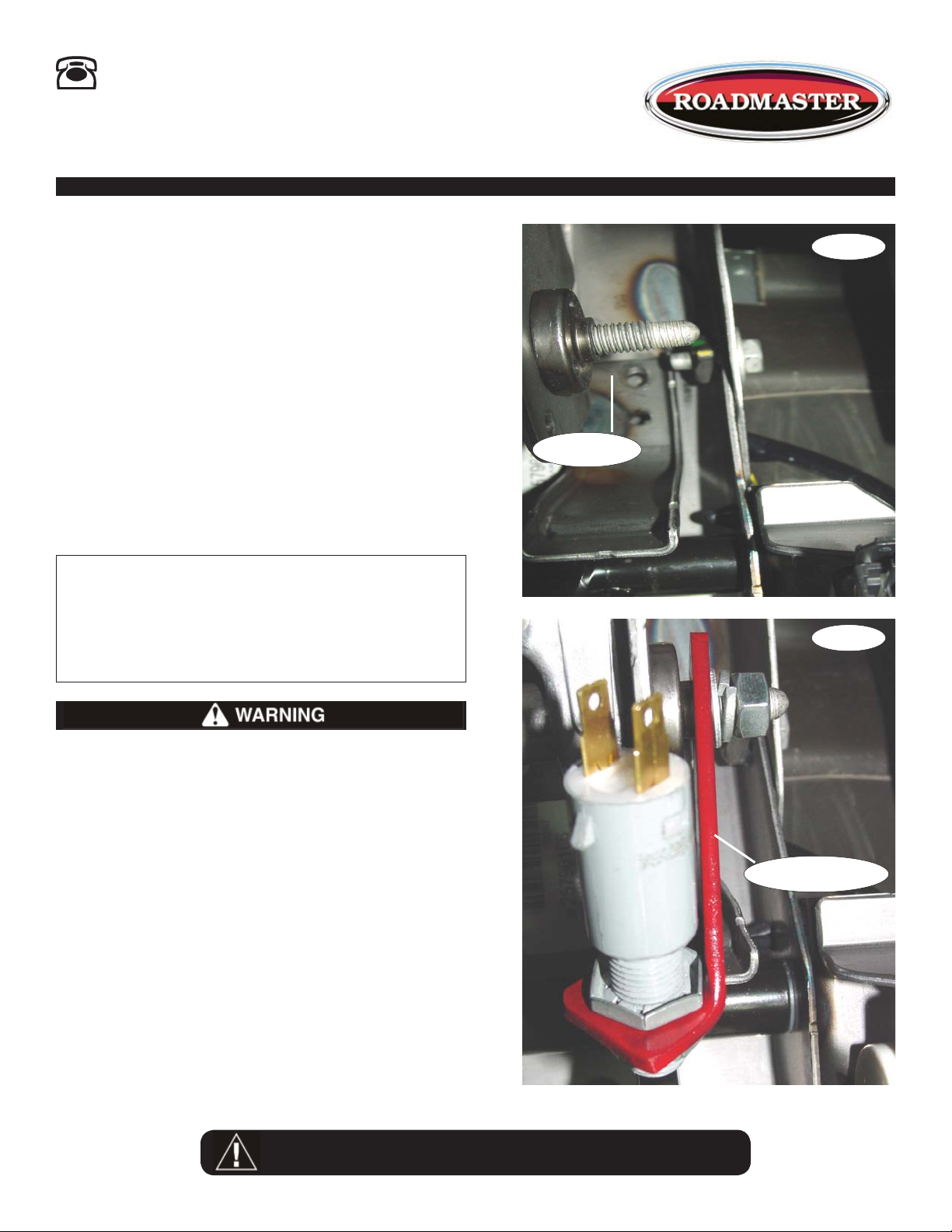
2. Locate the existing stud under the steering column
(Fig.A).
ALL SPECIFICATIONS ARE SUBJECT TO CHANGE WITHOUT NOTICE
Fig.A
3. Place the stop light switch bracket over the existing stud and bolt into place using the supplied 8mm
x 1.25 nut, 8mm flat washer and 8mm lock washer
(Fig.B).
4. Install and wire the stop light switch according to the
instructions provided with it. Be certain to adjust as
necessary to allow for proper activation of the plunger
on the switch.
Parts List
(1) 8mm x 1.25 nut
(1) 8mm flat washer
(1) 8mm lock washer
WARNING
When the installation is complete, verify that the
brake pedal retracts fully.
Unless they are installed correctly, the bracket and/
or other kit components may restrict or impede the
movement of the brake pedal — the brake pedal will
not retract fully.
If the brake pedal does not retract fully, the brakes
will be applied continuously, which may cause severe
tire and/or brake system damage, as well as other consequential, non-warranty damage.
Failure to follow these instructions may cause property damage, personal injury or even death.
q
Existing Stud
Fig.B
q
Stop Light Switch
WARNING
Failure to follow these instructions can result in
property damage, personal injury or even death.
Page 2
Stop Light Switch
Installation Instructions
ROADMASTER, Inc. • 6110 N.E. 127th Ave. • Vancouver, WA 98682 • 800-669-9690 • Fax 360-735-9300 • roadmasterinc.com
I
nstall this kit if the brake lights do not function when the
ignition is turned to the “tow” position, or if the vehicle is
equipped with a “retained accessory power” feature — with
this feature, the vehicle’s electronics continue to function
normally for about ten minutes after the ignition key is
turned off. Then the electronics will no longer function,
which shuts off power to the stop light switch.
Install the stop light switch
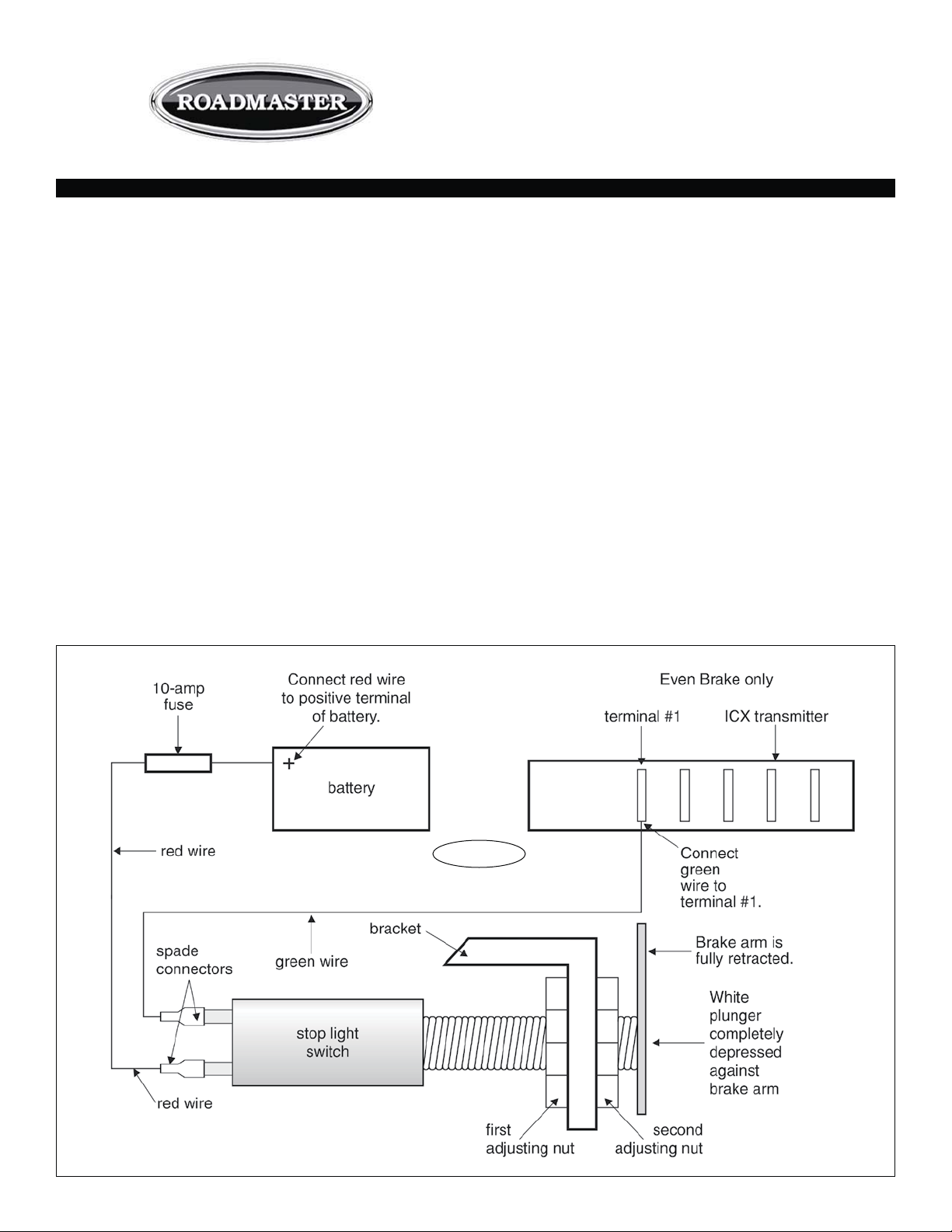
1. Thread the first adjusting nut (Figure A) through the
threaded portion of the stop light switch, with the open side
of the nut facing the terminals on the stop light switch.
2. Slide the threaded side of the stop light switch through
the bracket.
3. Thread the second adjusting nut through the threaded
portion of the stop light switch, with the open side of the
nut facing the white plunger on the stop light switch. (Do
not fully tighten the nut until the switch is installed.)
4. With the stop light switch in position, attach the bracket
— refer to the vehicle-specific mounting instructions that
are included with this kit.
5. With the brake arm (Figure A) fully retracted, turn the
All specifications are subject to change without notice.
Figure A
85-3483-05 02-13
adjusting nuts until the white plunger at the end of the
stop light switch is completely depressed.
CAUTION
The stop light switch must be installed as directed
above…
• The plunger must be completely depressed against
the brake arm. Otherwise, it may cause a false brake
light signal at the monitor.
• The brake arm must be fully retracted when the stop
light switch is installed. If it is not, the brake pedal
may depress the towed vehicle’s brakes continuously,
which will cause excessive brake wear, brake system
damage or other consequential, non-warranty damage.
6. Using the included spade connectors, connect the red
and green wires to the stop light switch terminals (Figure
A).
7. For Even Brake only — connect the green wire to the
terminal marked “1” on the Even Brake ICX transmitter
continued on next page
Towing and Suspension Solutions
Page 3

continued from preceding page
(Figure A).
For all ROADMASTER braking systems except Even
Brake — using a butt connector, connect the green wire
to the motorhome monitor wire.
Wire the switch to power
8. Power for the switch can come from either the battery
or the fuse block. The fuse block is typically an easier
connection; however, it cannot be used if the vehicle has
retained accessory power (see page one).
Option 1 — Power from the fuse block
Identify a circuit in the fuse block that is constantly
powered when the ignition key is in the “tow” position
(Figure B). Use the included fuse tap to attach the red wire
to the “cold” side of the fuse socket, as shown in Figure
B.
Note: the fuse tap cannot be attached to a low-profile
mini fuse. If necessary, replace a low-profile mini fuse with
a standard mini fuse of the same amperage.
Be certain to install the included 10-amp inline fuse
as shown.
Option 2 — Power from the battery
Using the provided 10 amp fuse (Figure A), connect the
red wire to the positive terminal on the vehicle’s battery.
Note: if the vehicle’s battery must be disconnected
for towing and a battery disconnect device has been installed, make certain that the red wire is connected to
the positive side of the battery disconnect device. In this
manner, 12VDC+ will be present when the battery is disconnected.
Test for proper function
After the stop light switch has been installed, test for
proper function…
1. With a circuit tester, verify 12VDC+ on both stop light
spade connectors with the brake pedal depressed.
2. With a circuit tester, verify 12VDC+ on only one spade
connector with the brake pedal released.
3. With the vehicle’s engine on, verify that the brake lights
illuminate only when the brake pedal is depressed.
4. With the engine still on, depress the brake pedal to its
farthest extent, then allow it to fully return. Make certain
that the stop light switch bracket or other kit components
do not impede the full and complete movement of the
brake pedal.
When the installation is complete, verify that the
brake pedal retracts fully.
Unless they are installed correctly, the bracket and/
or other kit components may impede the movement
of the brake pedal.
If the brake pedal does not retract fully, the brakes
will be applied continuously, which may cause severe
tire and/or brake system damage, as well as other
consequential, non-warranty damage.
Failure to follow these instructions may cause property damage, personal injury or even death.
Figure B
 Loading...