

Page 1
Page 2
TECH HANDBOOK FOR LIVE ROLLER CURVES/SPURS
TABLE OF CONTENTS
2
TECH HANDBOOK FOR BELT DRIVEN LIVE ROLLERS ................................................ 2
-Caution Labels ................................................................................................. 2
CAUTIONS, WARNINGS AND HAZARDS .............................................................. 3
-Introduction ..................................................................................................... 3
-Cautions, Warnings and Hazards....................................................................... 3
SAFETY INFORMATION / RECEIVING & INSPECTION.............................................. 4
-Important Safety Guidelines................................................................................ 4
-Shortages, Damages and Return Authorizations ..................................................... 4
GENERAL INSTALLATION INFORMATION .............................................................. 5
-Slave Drive / Mating to Other Conveyors ............................................................ 5
-Identifying / Installing Permanent Floor Supports .................................................... 5
CEILING HANGERS AND POLYTIER SUPPORTS........................................................ 6
-Installation of Ceiling Hangers ............................................................................ 6
-Installation of Polytier Supports ............................................................................ 6
INSTALLATION OF BELTING ................................................................................. 7
-V-Belt Connections............................................................................................ 7
-Adjusting V-Belt Tension ..................................................................................... 7
-V-Belt Drive Pressure Adjustment .......................................................................... 8
-Replacing V-Belt And Sheaves ............................................................................ 8
V-BELT PATH ....................................................................................................... 9
-V-Belt Path for Spurs And Curves ......................................................................... 9
START-UP PROCEDURES ..................................................................................... 10
-Drive Chain and Sprocket Alignment ................................................................. 10
-Drive Chain and Sprocket Tension .................................................................... 10
-Gear Reducer Vent Plug .................................................................................. 11
-Preparing for Initial Start-Up .............................................................................. 11
MAINTENANCE SAFETY PRECAUTIONS ............................................................... 12
-Before Performing Maintenance ........................................................................ 12
-Maintenance and Follow-Up Details .................................................................. 12
MAINTENANCE AND LUBRICATION.................................................................... 13
-Periodic Maintenance Schedules ....................................................................... 13
-Recommended Lubricants ................................................................................. 14
-Report on Miscellaneous Maintenance Performed, Chart 1 .................................... 14
TROUBLE SHOOTING AND REPLACEMENT PARTS ................................................. 15
-Trouble Shooting / Serial Plate ......................................................................... 15
MODEL 138LRC ................................................................................................ 16
-Parts List for Unit With End Drive / Side Mount End Drive ..................................... 16
-Illustrations for Unit With End Drive / Side Mount End Drive .................................. 17
MODEL 196LRC ................................................................................................ 18
-Parts List for Unit With End Drive / Side Mount End Drive ..................................... 18
-Illustrations for Unit With End Drive / Side Mount End Drive .................................. 19
MODEL 138LRCS ............................................................................................... 20
-Parts List for Unit With End Drive / Side Mount End Drive ..................................... 20
-Illustrations for Unit With End Drive / Side Mount End Drive .................................. 21
MODEL 196LRCS ............................................................................................... 22
-Parts List for Unit With End Drive / Side Mount End Drive ..................................... 22
-Illustrations for Unit With End Drive / Side Mount End Drive .................................. 23
WARRANTY ..................................................................................................... 24
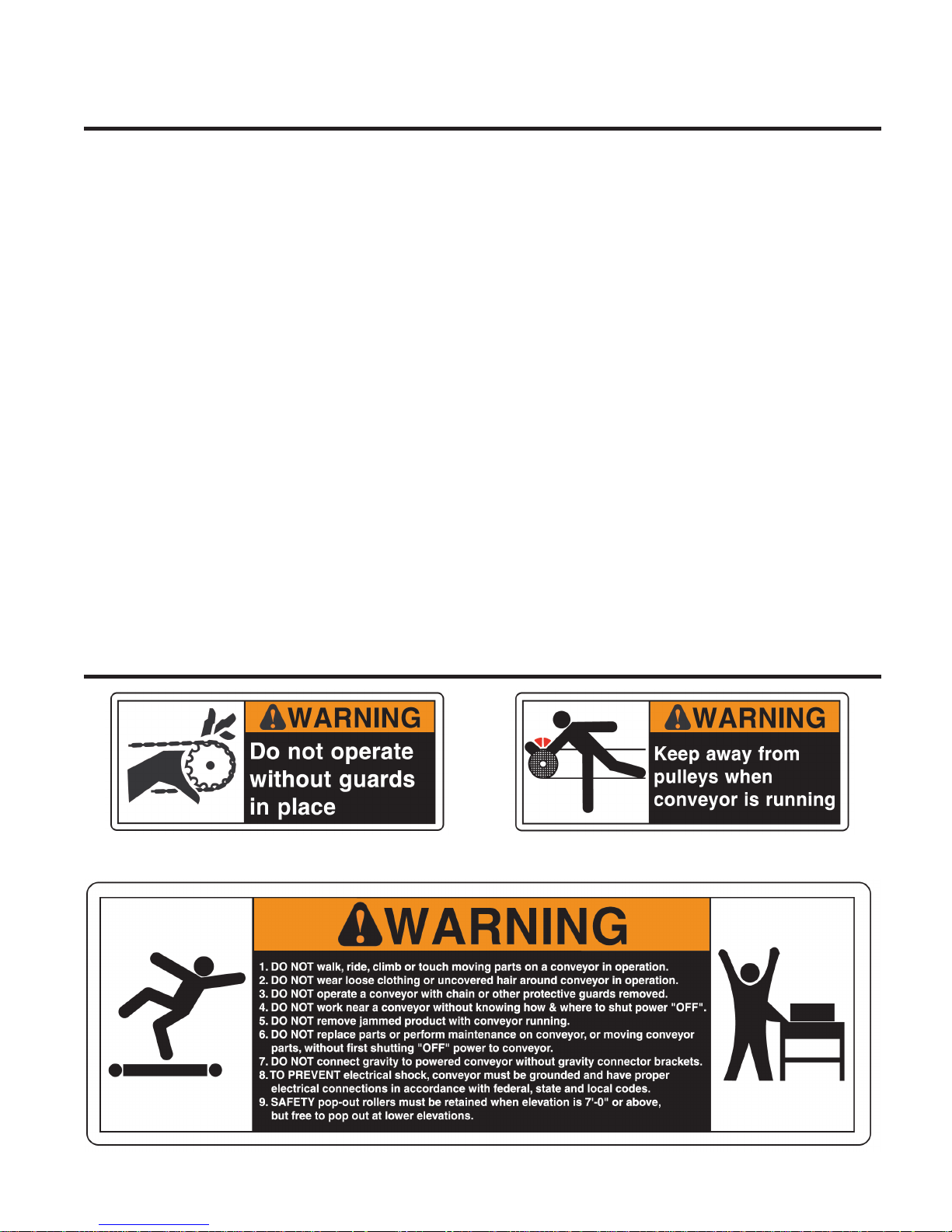
WARNING LABELS
ABOVE: Label attached to all protective guards (drives, roller guards, etc.) ABOVE: Label placed near all pulleys (center drives, end drives, tail pulleys)
ABOVE: Label placed near all drive assemblies and at 30’ intervals
Page 3
CAUTIONS, WARNINGS AND HAZARDS
INTRODUCTION
3
This manual was prepared as a “how-toguide” for installers, end-users and maintenance personnel. It is also intended to
educate both owner (purchaser) and all
individuals working around the unit, of
potential hazards.
With proper installation and maintenance,
conveyors are essential for achieving a variety of functions essential in today’s industrial
marketplace. By following a
simple, periodic maintenance schedule, the
life of a typical conveyor (or, most any type
of machinery--including our automobiles!)
will increase when compared to a similar
unit in an application receiving little or
no maintenance. You may find that a
conveyor can become your best workplace
friend by following simple safety guidelines.
Failure to follow even the most basic safety
suggestions can result in
serious personal injury.
Conveyors contain many moving parts-
-pulleys, belting, chains, sprockets, shafts,
rollers, etc. Therefore, it is imperative to
become familiar with basic unit operation
and know all points of potential hazards.
Remember, when working around or near
conveyors (and any industrial machinery)
DO NOT OPERATE BEFORE READING THIS MANUAL!
KEEP IN SAFE PLACE--DO NOT DISCARD!
it is your responsibility to become familiar
with the unit, to know potential hazards
(many are noted with caution labels) and
to operate unit in strict accordance with the
safety guidelines in this manual.
Keep this manual in a safe place for future
reference. It should be placed where
appropriate personnel may maintain
proper maintenance and records.
This manual must be read by all new users
before operating or working near this unit.
CAUTIONS, WARNINGS AND HAZARDS
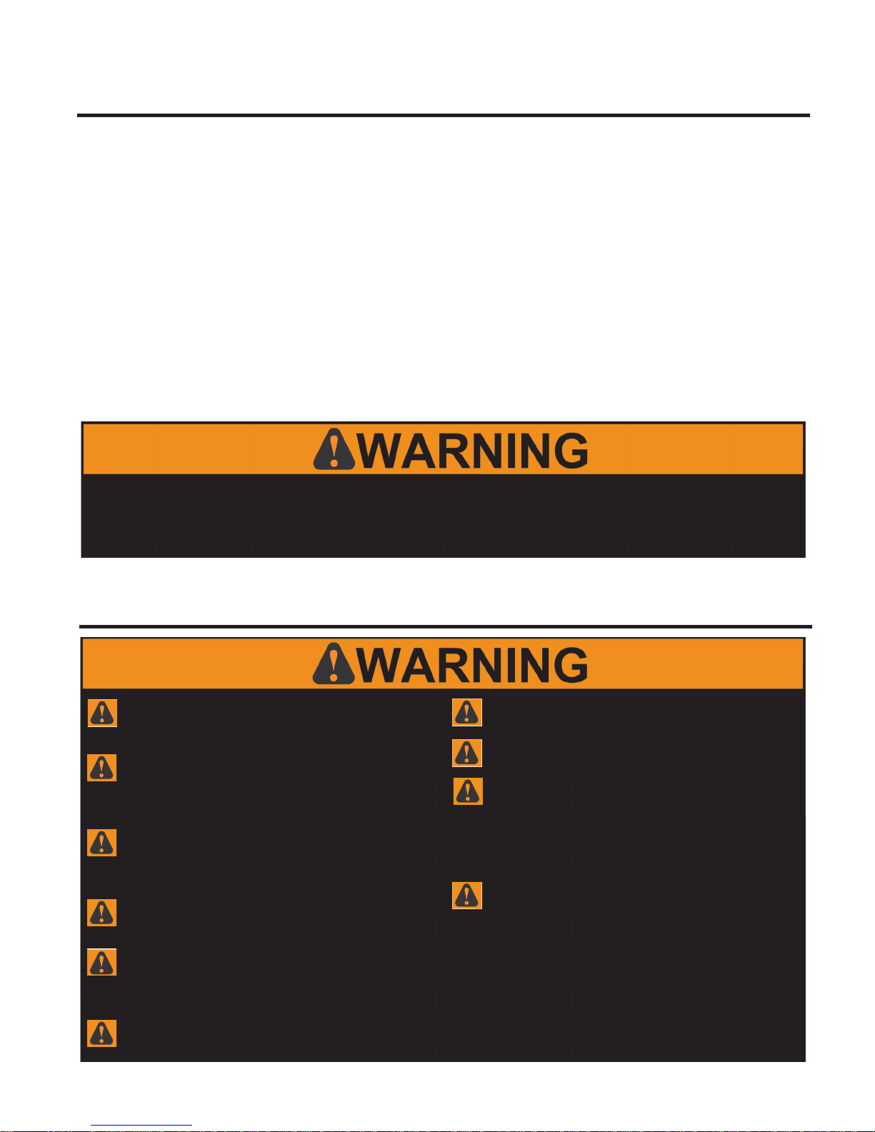
ALWAYS anchor permanent supports to floor (or mounting
surface). Use 3/8” x 2-1/2” (or longer) wedge anchors for
permanent installation in concrete flooring.
It is the responsibility of the customer and installation personnel
to supply and install net or mesh guarding on overhead mounted
conveyors to prevent product and/or debris from falling to floor in areas
where required.
Safety finger guards must NOT be removed form V-belt driven live
roller curves or spurs. If guard is removed for maintenance or other
purposes, conveyor must NOT be placed into operation until All finger
guards have been replaced.
Belt must be kept in good condition for safe work environment.
Drive chain guards MUST be replaced after installation or mainte-
nance before unit start-up. Also, guards used to cover slave drive
connections for slave driven curves or spurs must be replaced prior to startup after installation or maintenance.
To check drive sprocket alignment, shut “OFF” and lock out power
source before attempting ANY adjustments.
To check drive sprocket tension, shut “OFF” and lock out power
source before ANY adjustments are attempted.
To check drive sprocket tension, shut “OFF” and lock out power
source before ANY adjustments are attempted.
Electrical controls must be designed by a qualified electrical engi-
neer to ensure that appropriate safety features (emergency stops,
pull cords, switches, etc.) are installed on unit for safe operation. Before
conveyor start-up, all operators and other personnel coming in contact
with unit must be properly trained and must have read accompanying
Tech Handbook.
Only trained personnel shall perform maintenance functions. Before
maintenance operations are performed, shut conveyor “OFF” and
lock out power source to prevent unauthorized start-up. When maintenance is completed, only authorized personnel shall be permitted to start
conveyor following maintenance or other emergency shut-off.
Page 4
SAFETY INFORMATION / RECEIVING & INSPECTION
4
IMPORTANT SAFETY GUIDELINES
WARNING: All personnel coming in contact with this conveyor should be aware of the following safety guidelines BEFORE USING OR
WORKING AROUND CONVEYOR. NOTE: ALWAYS notify Roach Manufacturing® whenever any conveyor is used in an application
or condition other than was originally intended. Failure to notify Roach
condition. Injuries resulting from negligence or violation of safety instructions hereby removes responsibility of product liability claims from
Roach®. Any violation of above safety instructions hereby removes all product liability claims from Roach.
®
may allow conveyor to be operated in a hazardous operating
Do not operate conveyor with
protective guards removed. This
includes chain guards, belt guards, snub roller
guards, center drive guards and
any other safety guard.
Do not walk, ride, climb, or touch
moving parts on a conveyor in
operation.
Do not wear loose clothing or
uncovered hair around conveyor.
Do not work near conveyor without
knowing how & where to shut power
“OFF” and lock out power source.
Do not remove jammed product with
conveyor running.
Do not replace parts or perform
maintenance on conveyor, or moving
conveyor parts, without first shutting “OFF”
power to conveyor and locking out power
source.
Do not connect gravity to powered
conveyor without safety gravity
connector brackets.
To prevent electrical shock, conveyor
must be grounded, and have proper
electrical connections in accordance with
federal, state, and local codes.
Safety pop out rollers in conveyors
installed above 7’-0” elevation must be
retained by guard rail, clips, etc. Safety pop
out rollers must be allowed to pop out when
conveyors are installed at or below
7’-0” elevation.
standards including OSHA and other federal,
state, and local codes or regulations. Install
protective guarding and other related safety
precautionary equipment to eliminate
hazardous operating conditions which may
exist when two or more vendors supply
machinery for related use.
product liability claims from Roach
Manufacturing Corporation
It is the responsibility of conveyor
end-user to comply with all safety
Any violation of above safety
instructions hereby removes all
®
.
SHORTAGES, DAMAGES AND RETURN AUTHORIZATIONS
NOTE: Do not return goods to factory
without prior, written return authorization.
Unauthorized returns are subject to refusal
at factory. Also, some items (electric
motors, gearbox, etc.) may be shipped
direct from their manufacturer. Thus,
two or more separate shipments may be
required to receive all equipment.
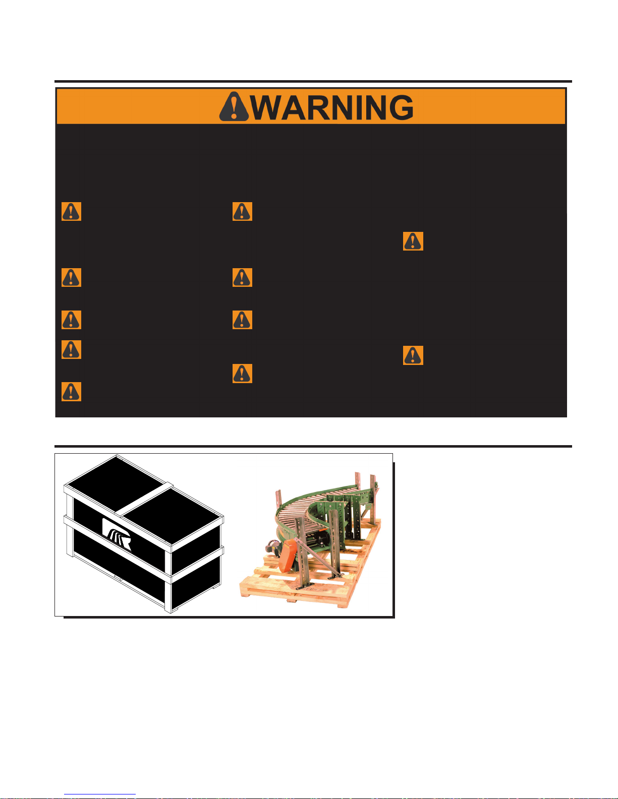
Before uncrating, check quantity of items
received against bill of lading to confirm
that all equipment has been received.
Next, determine if any damage has
occurred. Damage and/or shortage in
shipment should be reported immediately
to both Roach and carrier. Obtain signed
damage report from carrier agent and send
copy to Roach. Do not repair any damage
before obtaining this report. Finally, consult factory to determine if entire shipment
must be returned to factory for repair or if
a replacement order should be entered for
replacement equipment.
Therefore, it is imperative that the bill of
lading (or, accompanying freight documentation) be checked to ensure receipt of ALL
units ordered including ALL accessories.
After receipt and initial inspection, carefully
remove crating and look for essential components and specific accessories that may
have been boxed and attached (or ‘banded’) to crating material such as guard rails
and hardware which may be packaged
and shipped in this manner. Save all
hardware for subsequent use by installation
personnel.
Page 5
GENERAL INSTALLATION INFORMATION
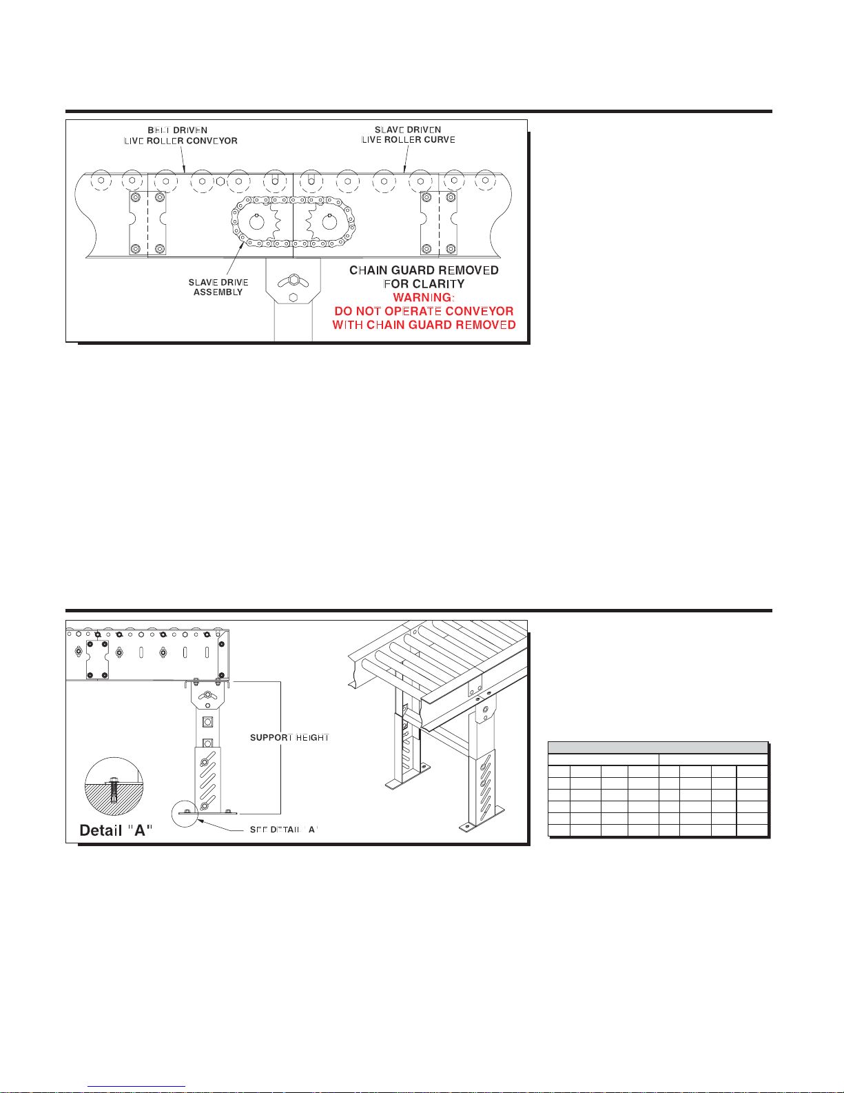
SLAVE DRIVE / MATING TO OTHER CONVEYORS
NOTE: There are two primary methods of
installation for a curve--driven by its own
gear motor or SLAVE driven from another
conveyor.
5
Once conveyor is uncrated, installation of
curve or spur may begin (note that in following text we will use “curve” for reference to
both curves and curve spurs). Locate unit in
the actual installation area.
There are two primary methods of installation for a curve--driven by its own gear
motor or SLAVE driven from another conveyor. Most often, curves are SLAVE driven
by belt driven live rollers or slider bed belt
conveyors, which eliminates gear motor
drive assembly for curve.
Locate actual bed section of conveyor
which is to slave drive curve to begin installation. Note that this conveyor is usually
set up before curve is installed. Bed section labels are located on bed of driving
conveyor showing where slave driven curve
will be installed (see illustration above). For
curves not slave driven, location of installation in most usually noted by conveyor
“mark numbers”.
Use mechanical hoist (fork truck or other
available means) to raise bed sections to
approximate installed elevation. Locate supports, attach to curve and mate curve with
butt couplings.
IDENTIFYING/INSTALLING PERMANENT FLOOR SUPPORTS
CAUTION: Always anchor permanent sup-
ports to floor (or mounting surface). Use
3/8” x 2-1/2” (or longer) wedge anchors
for permanent installation in
concrete flooring.
*MINIMUM SUPPORT HEIGHT
MEDIUM DUTY HEAVY DUTY
SM-1 7-1/4” SM-7 34-1/4” SH-1 6-1/4” SH-7 25-3/4”
SM-2 10-1/4” SM-8 46-1/4” SH-2 7-3/4” SH-8 31-3/4”
SM-3 13-1/4” SM-9 58-1/4” SH-3 10-3/4” SH-9 43-3/4”
SM-4 16-1/4” SM-10 70-1/4” SH-4 13-3/4” SH-10 55-3/4”
SM-5 20-1/4” SM-11 80-1/4” SH-5 16-3/4” SH-11 67-3/4”
SM-6 24-1/4” SM-12 92-1/4” SH-6 19-3/4” SH-12 29-3/4”
It is most common to use single tier permanent floor supports at each end of a curve,
for models 138LRC and 196LRC. In the
center of the curve, a single leg support is
required underneath the outside frame rail.
If the frame rail consists of two or more
frame rails and is joined together in the center of the curve, a full support is required.
For model 138LRCS and 196LRCS curve
spurs, two supports are generally required,
one support at the junction between the
spur and the curve and one support at the
tangent end of the curve.
Adjust elevation to top of conveyor by
loosening bolts in support uprights, raising
or lowering conveyor and fully tightening
bolts at desired elevation. Tighten all bolts
Complete support installation by lagging
support attachment plates to floor with two
lag bolts in a diagonal pattern in support
foot plate mounting holes. Conveyor
must be level across width of unit before
completing final support height adj.
*Supports are normally shipped at minimum
support height. See chart above.
in supports before unit operation.
Page 6
CEILING HANGERS AND POLYTIER SUPPORTS
INSTALLATION OF CEILING HANGERS
WARNING: It is the responsibility of the
customer and installation personnel to supply and install net or mesh guarding on
conveyors mounted overhead to prevent
product and/or debris from falling to floor
in areas where required.
6
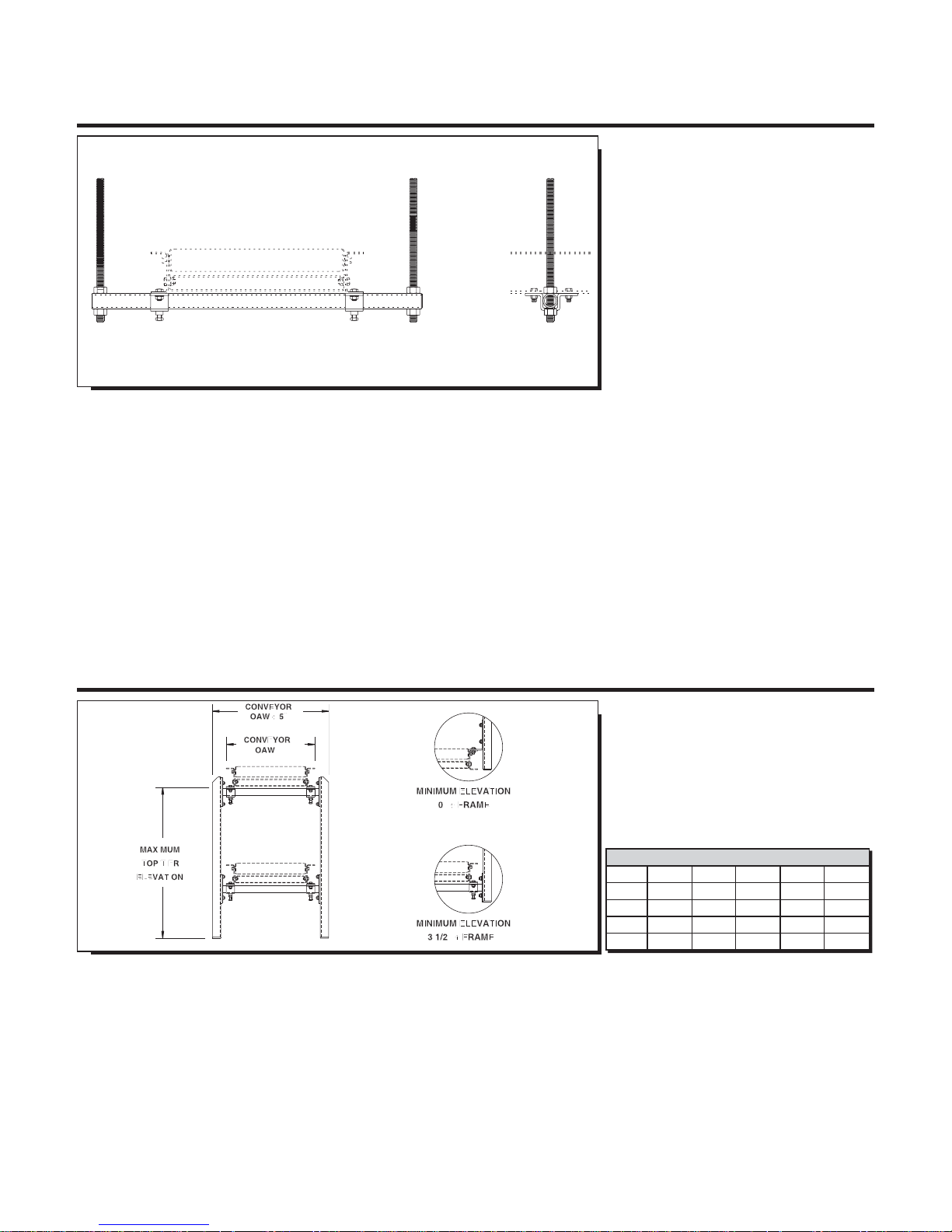
Ceiling hangers are frequently used in highelevation applications for suspension from
ceiling. The 5/8” diameter (#11 UNC)
all threaded rod is supplied to allow infinite
vertical adjustment along the length of the
suspension rod (see illustration above).
Attach and firmly tighten U-shaped retainer
(“hat”) bracket to underneath side of lower
conveyor flange with hardware provided
to hold cross pipe (1” inside diameter)
against underneath side of conveyor.
Do not tighten cross pipe locking bolts
(these attach in the bottom of the U-shaped
retainer bracket) until threaded suspension
rods have been firmly secured to ceiling
structure.
To adjust conveyor elevation, tighten or
loosen lower nut and jam nut on threaded
INSTALLATION OF POLYTIER SUPPORTS
suspension rods to desired elevation. A
lock washer must be used on suspension
rods to maintain unit at desired elevation.
When unit is at operating elevation and unit
has been levelled across bed width, tighten
locking bolts in U-shaped bracket
to secure position of cross pipe.
NOTE: To install, raise conveyor to
desired elevation, place cross pipe
underneath lower conveyor flange,
attach cross pipe to upright legs and use
U-shaped retainer (“hat”) bracket to connect cross pipe to lower conveyor flange.
POLYTIER SUPPORT CHANNEL HEIGHT
PSM-1 23” PSM-6 53” PSM-11 83”
PSM-2 29” PSM-7 59” PSM-12 89”
PSM-3 35” PSM-8 65” PSM-13 95”
PSM-4 41” PSM-9 71” PSM-14 101”
PSM-5 47” PSM-10 77” PSM-15 107”
Polytier supports provide convenient
installation method for two or more tiers
of conveyor. To install, raise conveyor to
desired elevation (approximate). Place 1”
inside diameter cross pipe underneath
lower conveyor flange. Attach cross pipe
to upright legs. Use U-shaped retainer
(“hat”) bracket to connect cross pipe to
lower conveyor flange. Do not tighten
fully at this time.
There are two styles of attachment brackets
available for use with polytier supports.
Minimum elevation style (see illustration
above) offers lowest unit elevation, 0” +
depth of frame utilizing L-shaped mounting
bracket. Standard elevation style offers
unit elevation of 3-1/2” + depth of frame
When unit is at operating elevation and unit
has been checked across width for
level, tighten locking bolts in U-shaped
bracket. Add knee braces for unit rigidity.
*NOTE: Overall conveyor height is dictated by type of drive assembly used--i.e.
underneath, center drive, side mount, etc.
and includes bracket welded to cross pipe
which is bolted to upright legs during installation.
Page 7
INSTALLATION OF BELTING
V-BELT CONNECTIONS
7
WARNING: Safety finger guards are
located above V-belt on all live roller
curves and spurs. Removal of finger guard
assemblies may result in serious injury to
personnel stationed near or coming in
contact with conveyor. V-belt must be kept
in good condition and belt tension must be
properly adjusted for safe work environment. BEFORE ANY ADJUSTMENTS ARE
ATTEMPTED, SHUT “OFF” AND LOCK
OUT POWER SOURCE.
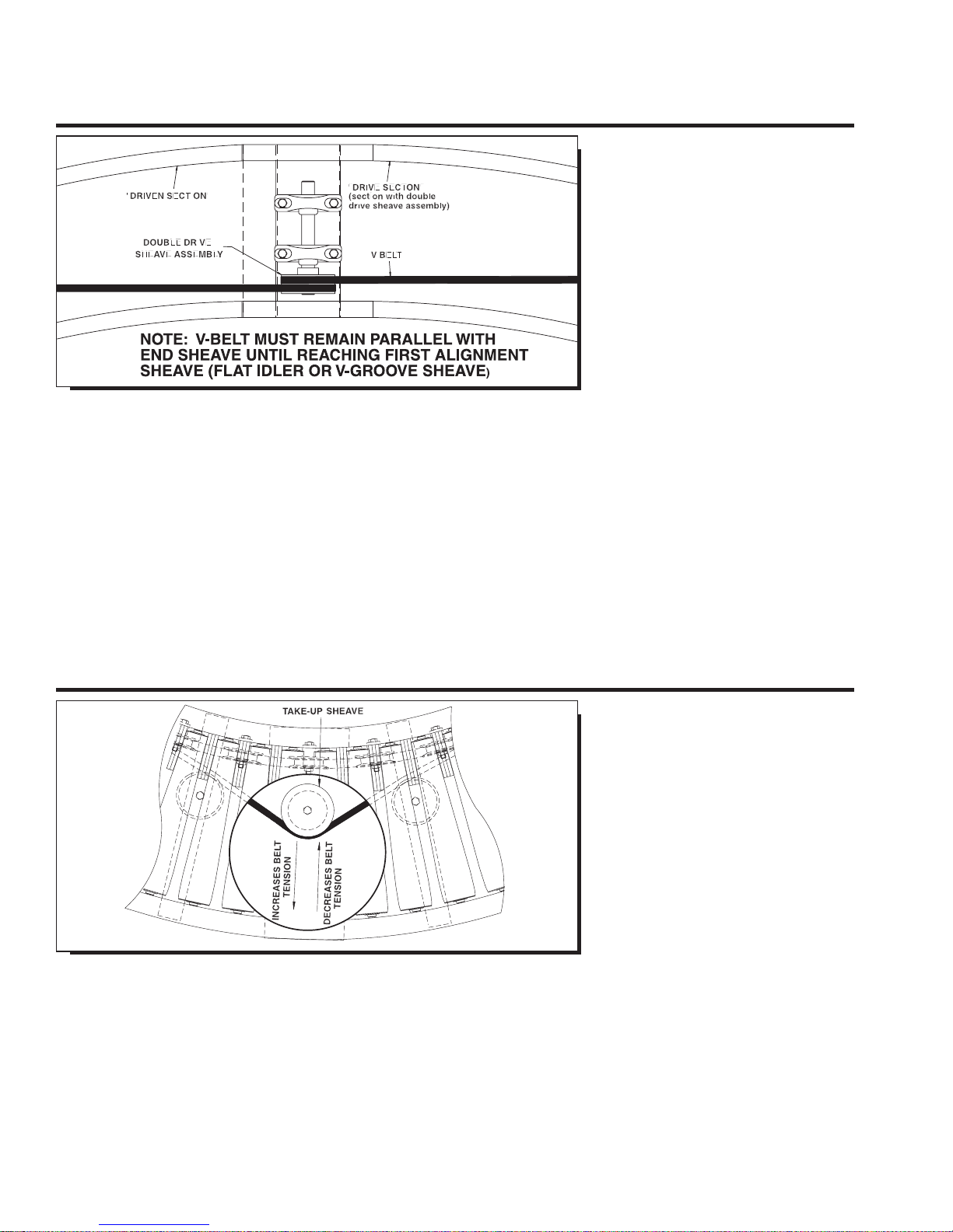
In some applications (180 degree, long
straight tangents, etc.), curves are manufactured in two or more sections requiring
the use of more than a single drive belt.
Although set up and test run (and, subjected
to quality control inspection) at the factory,
unit may require disassembly for
shipping. In such cases, V-belt must be
re-connected before operation.
To reconnect belts, determine curve section
containing double sheave drive assembly,
or “drive section” in illustration above. This
drive section features drive V-belt shipped
mounted as required. The V-belt on the
adjoining curve section, or “driven section”,
must be attached to double sheave drive
assembly. To install, loosen V-belt take-up
sheave on driven section to allow adequate
ADJUSTING V-BELT TENSION
slack in V-belt for attachment to double
sheave. Then, complete
V-belt assembly by properly adjusting
take-up sheave in center of driven section as
outlined in following section.
NOTE: Depending on the model or BF
of curve or spur, there are several take-up
configurations available. See page 9 of
manual for more information.
WARNING: Safety finger guards are
located above V-belt on all live roller
curves and spurs. Removal of finger guard
assemblies may result in serious injury to
personnel stationed near or coming in contact with conveyor. V-belt must be kept in
good condition and belt tension must be
properly adjusted for safe work environment. BEFORE ANY ADJUSTMENTS ARE
ATTEMPTED, SHUT “OFF” AND LOCK
OUT POWER SOURCE.
Maintaining proper belt tension is vital to
proper unit operation and long V-belt life.
Over-tensioning drive belt requires more
horsepower, decreases belt life and may
harm unit drive and take-up sheaves.
To increase drive belt tension (or, to take
up slack in V-belt), move take-up sheave
toward outside of curve (or spur) by adjusting take-up rod on take-up sheave (see illus-
tration above). Be careful not to
over-tension belt.
To “decrease” belt tension, move take-up
sheave toward inside of curve (or spur) by
adjusting take-up rod on take-up sheave.
When adjustment is complete, tighten jam
nut to complete tensioning procedure.
Make adjustments to drive belt in small
increments.
For adjusting drive pressure applied to
V-belt from drive sheaves, see next section.
NOTE: When adjusting V-belt tension,
V-belt must remain parallel with end sheave
until reaching first alignment sheave (sheave
may be flat idler or V-grooved).
Page 8
INSTALLATION OF BELTING
V-BELT DRIVE PRESSURE ADJUSTMENT
8
WARNING: Safety finger guards are
located above V-belt on all live roller
curves and spurs. Removal of finger guard
assemblies may result in serious injury to
personnel stationed near or coming in
contact with conveyor. V-belt must be kept
in good condition and belt tension must be
properly adjusted for safe work environment. BEFORE ANY ADJUSTMENTS ARE
ATTEMPTED, SHUT “OFF” AND LOCK
OUT POWER SOURCE.
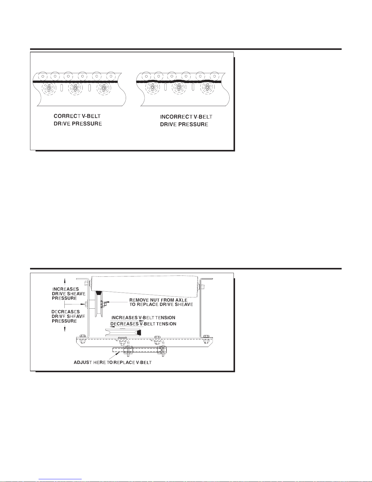
Maintaining proper drive belt pressure is
vital to proper unit operation and long
V-belt life. Over-applying drive belt pressure requires more horsepower and may
harm unit drive and take-up components.
Belt life is drastically reduced when unit is
operated with incorrect drive belt pressure.
Belt driven live roller curves and spurs
require adequate drive pressure on the
drive belt to convey the heaviest unit load.
Therefore, if curve or spur does not properly
convey the heaviest unit load, adjust the
drive belt pressure as outlined below.
To increase drive belt pressure, move
sheave “up” (see above illustration) toward
roller. To decrease drive belt pressure,
lower sheave away from roller. Make
REPLACING V-BELT AND SHEAVES
adjustments in small increments. DO NOT
place too much drive pressure on sheaves.
In worst conditions, conveyor may stall, thus
causing motor to overheat and
untimely unit shut down, when drive sheaves
have been raised too high.
WARNING: Safety finger guards are
located above V-belt on all live roller
curves and spurs. Removal of finger guard
assemblies may result in serious injury to
personnel stationed near or coming in
contact with conveyor. V-belt must be kept
in good condition and belt tension must be
properly adjusted for safe work environment. BEFORE ANY ADJUSTMENTS ARE
ATTEMPTED, SHUT “OFF” AND LOCK
OUT POWER SOURCE.
As outlined in previous sections, the importance of properly setting drive tension and
drive pressure on V-belts simply cannot be
overstated. When V-belt or drive sheaves
are out of adjustment, life of sheaves and
V-belting may be drastically reduced, thus
requiring untimely replacement(s).
Before ANY maintenance operations are
performed on belt driven live roller curves
or spurs, it is VITAL that ALL conveyors are
shut “OFF” and power source is locked out.
Confirm that power source has been locked
out before beginning maintenance.
For replacing V-belt, remove conveyor tread
rollers, loosen take-up assembly as previously noted and remove belt. Use
old belt to identify replacement, which is
readily available from Roach or may be
purchased locally to expedite replacement
procedure. Install new belt, tread rollers
and re-set belt tension.
Should any drive sheaves require replacement, consult Roach distributor for new
sheaves. Remove nut from drive sheave
axle, remove worn sheave and replace with
new unit. Replace nut and set drive sheave
pressure as previously outlined.
Page 9
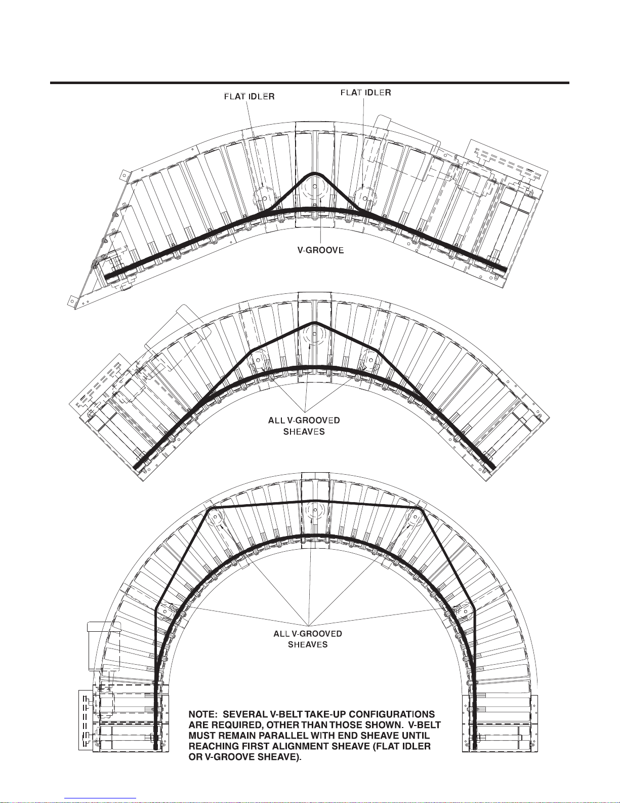
V-BELT PATHS
V-BELT PATH FOR SPURS AND CURVES
9
Page 10
START-UP PROCEDURES
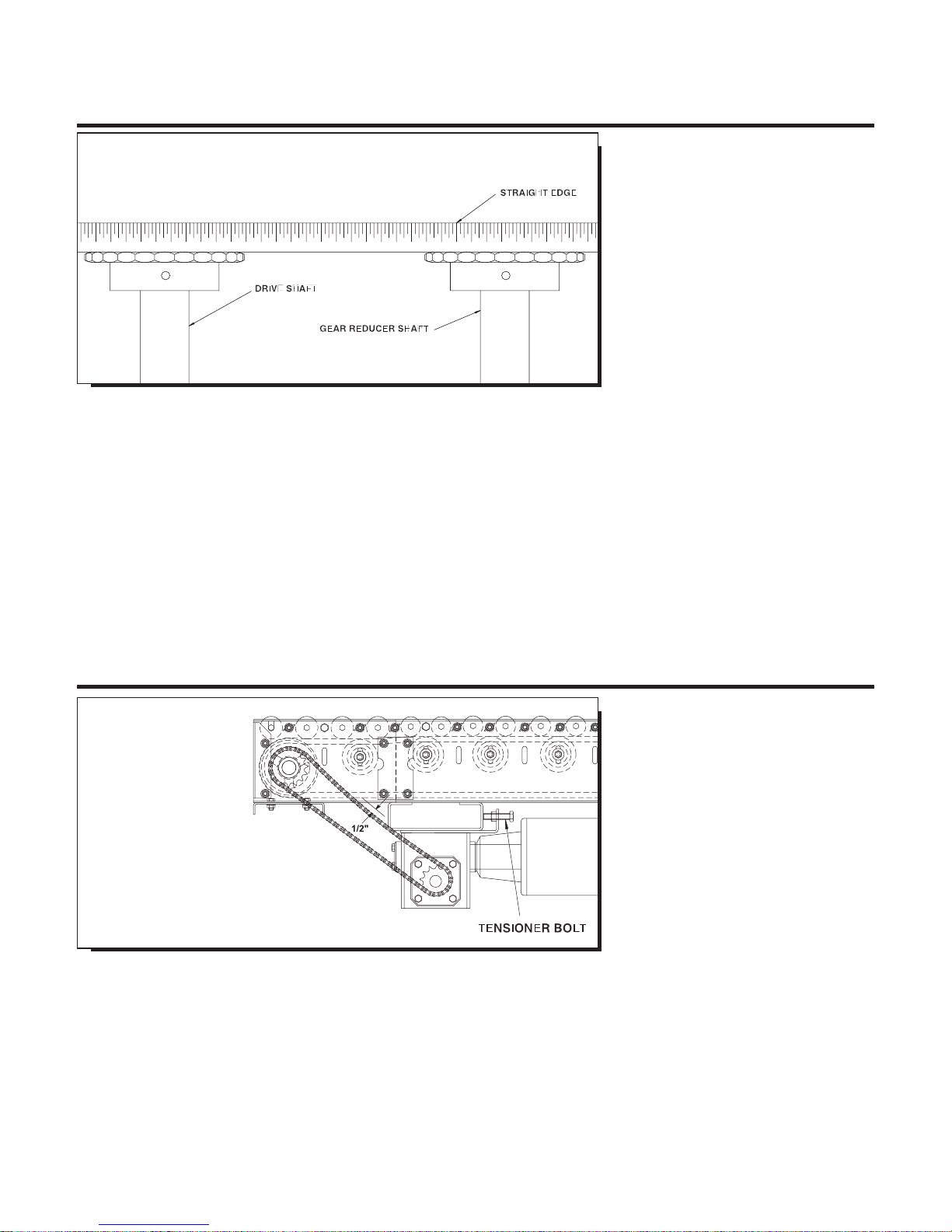
DRIVE CHAIN AND SPROCKET ALIGNMENT
10
CHAIN GUARD REMOVED FOR CLARITY
WARNING: DO NOT OPERATE CONVEYOR
WITH CHAIN GUARD REMOVED
Set up and maintenance of drive sprocket
and drive chain alignment is critical (on
curves or spurs with drive assembly). A
periodic visual inspection is recommended
to confirm alignment of drive components
(which includes both drive sprockets and
drive chain). Should set screws become
loose, drive sprockets are subject to
excessive wear and ultimately, to untimely
replacement.
To check drive sprocket alignment, it is
imperative that conveyor is shut “OFF”
and power source is locked out before
any adjustments are attempted. Remove
chain guard cover and place straight-edge
(see illustration above) across face of
both drive sprockets. If re-alignment is
WARNING: To check drive sprocket
alignment, it is imperative that conveyor is
shut “OFF” and power source is locked out
before any adjustments are attempted.
necessary, loosen set screws and adjust
drive sprockets as required. Remember
to securely tighten set screws when alignment is complete.
Before replacing chain guard cover,
check drive chain tension as described
in following section, “Drive Chain and
Sprocket Tension.”
DRIVE CHAIN AND SPROCKET TENSION
CHAIN GUARD
REMOVED FOR CLARITY
WARNING: DO NOT
OPERATE CONVEYOR
WITH CHAIN GUARD
REMOVED
Maintaining proper chain tension is
especially important. Again, a periodic
visual inspection is recommended to
ensure chain tension within a pre-determined operating range.
Remember, before any adjustments are
attempted, conveyor must be shut “OFF”
and power source locked out.
to see if drive chain is operating within
1/2” range (see above illustration). If unit
is out of tolerance, adjustment is necessary.
To adjust drive chain tension, tensioner bolt
located on reducer push plate should be
tightened (rotate clockwise) if chain tension
is loose. Tighten until proper operating
range is achieved. If chain tension is too
WARNING: To check drive sprocket
tension, shut “OFF” and lock out power
source before any adjustments are attempted.
tight, loosen tensioner bolt (rotate counterclockwise) as required. When adjustment
is complete replace chain guard cover.
WARNING: Do not operate unit until
chain guard cover is replaced. Serious
operator or other personal injury could result
if protective guarding is not replaced.
Before replacing chain guard cover, check
Page 11
START-UP PROCEDURES
11
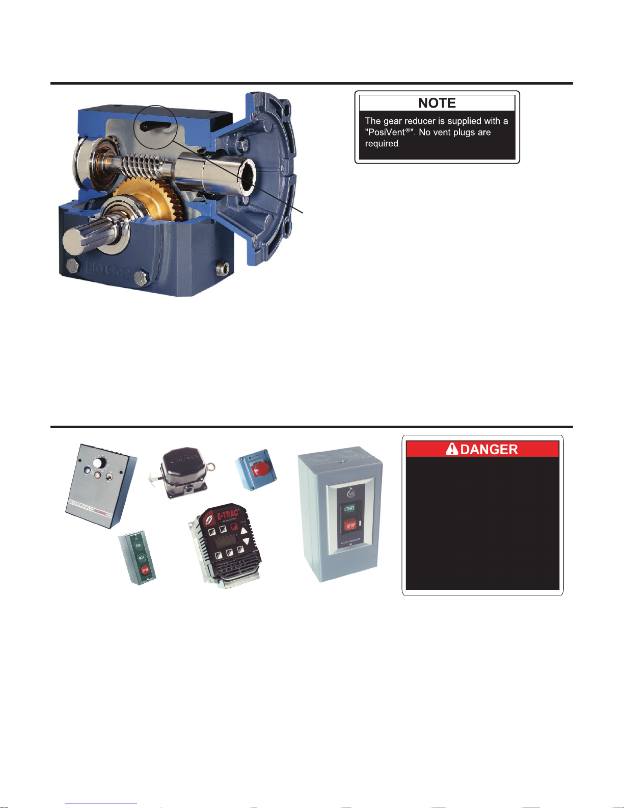
GEAR REDUCER VENT PLUG
PosiVent Unique design incorporates a single seam
construction. Factory filled with synthetic lubrication for
universal mounting. Lubed for life, no oil changes are
required.
To expedite the installation and start-up process, all gear red ucers are shipped filled with oil. The reducers are sealed and lubed for
life and require no oil changes.
PREPARING FOR INITIAL START-UP
Before conveyor start-up, all operators and
other personnel coming in contact with unit
must be properly trained and must have
read accompanying Tech Handbook.
Provisions must be in order to instruct all
personnel coming in contact with conveyor
on the location of emergency stops,
pull cords, etc.
A routine maintenance program should
be implemented before unit is placed into
operation so that fundamental unit components are attended to. This maintenance
program should include an inspection
to ensure that any dangerous or hazardous operating conditions are noted and
IMMEDIATELY corrected, as well as including
electrical and mechanical unit inspections
and corrections.
Finally, when conveyor is initially started,
WARN ALL PERSONNEL TO KEEP CLEAR OF
CONVEYOR DURING UNIT START-UP
Electrical controls must be designed by a
qualified electrical engineer to ensure that
appropriate safety features (emergency stops,
pull cords, switches, etc.) are installed on unit
for safe operation. Before conveyor start-up,
all operators and other personnel coming in
contact with unit must be properly trained
and must have read accompanying Tech
Handbook.
an immediate visual inspection should
include motor, gear reducer, belt tracking
(discussed in following section under “Belt
Tracking”) and related adjustments noted in
handbook for unit/component corrections.
Page 12

MAINTENANCE SAFETY PRECAUTIONS
12
BEFORE PERFORMING MAINTENANCE
CAUTION: Only trained personnel shall perform maintenance functions. Before maintenance operations are performed, conveyor must be
shut “OFF” and disconnects locked in the “OFF” position to prevent unit from unauthorized start-up.
One of the most important guidelines for maximizing conveyor
operation and personnel safety is to implement a regular maintenance schedule and train personnel on the appropriate needs of the
specific unit.
Only trained personnel shall perform maintenance functions. Before
maintenance operations are performed, conveyor must be shut
“OFF” and disconnects locked in the “OFF” position to prevent
unit from unauthorized start-up during maintenance. All personnel
should be informed of the safety procedures associated with unit
maintenance and performance.
Do not perform any work on conveyors or conveyor system while
in operation unless it is impossible to otherwise conduct adjustment, lubrication or other maintenance function. Only experienced,
trained personnel possessing advanced hazards-training should
attempt such critical operations.
MAINTENANCE AND FOLLOW-UP DETAILS
CAUTION: Only trained personnel shall perform maintenance functions. When maintenance is completed, only authorized personnel
shall be permitted to start conveyor following maintenance or other emergency shut-off.
While performing maintenance do not wear loose clothing.
Immediately report any hazardous conditions--sharp edges,
pinch (or nip) points or other conditions that may result when
several manufacturers supply machinery which may create
operating hazards.
When using mechanical aids such as hoists, cables, or cranes
exercise extreme caution to prevent damage to conveyors or other
integrated machinery which may create a working hazard when
maintenance is completed and units are in operation.
Clean up any spilled lubricants or other materials used in the
maintenance process or those which may be deposited during unit
operation. Eliminating poor housekeeping practices increases unit
efficiency while creating safer personnel working conditions.
After maintenance, conduct visual inspection to ensure that all safety
devices and guards have been replaced. Confirm that all units are
clear of tools, debris or other items. Before starting
conveyor, check condition of unit caution labels (see
“CAUTION LABELS” at front of handbook). If labels have been
destroyed or are not clearly legible, call 870.483.7631 to receive
replacement labels. Placement of caution labels is critical to avoid
unauthorized unit operation which may result in hazardous working
conditions for all related personnel coming in contact with conveyor.
Warn personnel that conveyor is being prepared for start-up and
to stay clear of unit. Do not start conveyor until all personnel are
clear. When maintenance is completed, only authorized personnel
shall be permitted to start conveyor following maintenance or other
emergency shut-off.
Page 13

MAINTENANCE AND LUBRICATION
PERIODIC MAINTENANCE SCHEDULE
MODEL NO.__________
WEEKLY RECOMMENDED MAINTENANCE SCHEDULE*
COMPONENT DETAIL OF MAINTENANCE
V-Belt Inspect belt tension and sheave drive pressure applied to V-Belt.
V-Belt Pressure Sheaves Check & re-tighten axles. Check for overall wear.
13
Pillow Block/Flange Bear-
ings
Unit Safety Check
Confirm placement of all guards including safety finger guards, pop-out rollers,
warning labels. Check for loose bolts, nip points & other hazards.
Lubricate in dirty, dusty or moist/wet conditions.
MONTHLY RECOMMENDED MAINTENANCE SCHEDULE*
COMPONENT DETAIL OF MAINTENANCE
Gear Reducer Check for leaks.
Drive Chain Check for proper operating tension & for overall wear & lubricate.
Drive Sprockets Check for overall wear & re-tighten set screws.
V-Belt Drive Belt Check for proper operating tension & overall wear.
Drive Sheaves Check & re-tighten set screws & check for overall wear.
Pillow Block/Flange Bear-
ings
Lubricate (normal conditions)
PERIODIC RECOMMENDED MAINTENANCE SCHEDULE*
COMPONENT DETAIL OF MAINTENANCE
Gear Reducer Check for leaks.
Drive Chain
Motor
*All charts are for guidelines in normal operating or ‘as noted’ conditions. Severe applications may warrant additional maintenance.
Clean (brush in solvent) & re-lubricate by applying lubricant to inside of chain with
brush or spout can at 2000 hour intervals.
Check & clear motor ventilation openings at 500 hour intervals
Check miscellaneous operating conditions (normal heat & noise).
Page 14

MAINTENANCE AND LUBRICATION
RECOMMENDED LUBRICANTS
MISC. LUBRICANTS
LUBRICANT BRAND/DESCRIPTION
14
General Purpose Grease
(For -30¯F to 300¯ operation)*
For extreme Temperature Operation
(-90¯F to 350¯F operation)*
Washdown Application*
(-30¯F to 225¯F operation)
(May require special consideration -- consult fac-
tory)
General Purpose Oil SAE 10; SAE 20 or SAE 30
*NOTE: Temperatures listed indicate the nominal operational temperature for the specific lubricant listed. This does not imply that the bearing housing, seals or any other conveyor unit component is rated to operate in this specific temperature range or environment.
250°F is the maximum operating temperature for standard bearing lubricants and bearing components. Although various lubricants may
enhance bearing operation, special-order bearings may be required to achieve optimal bearing performance. For additional
information, consult factory.
Shell Dolium R (Shell Oil Co.)
(or Suitable equivalent)
Mobiltemp SHC-32 (Mobil Oil Corp.)
(or suitable equivalent)
Shell Alvania No. 3 (Shell Oil Co.)
(or suitable equivalent)
MAINTENANCE AND LUBRICATION
REPORT ON MISCELLANEOUS MAINTENANCE PERFORMED
REPORT ON MAINTENANCE
CONVEYOR
MARK NO.
REPAIREDBYINSPECTION
DATE
DETAIL OF MAINTENANCE COMPLETED OR INSPECTED
LIST PARTS REPLACED OR REPAIRS
Page 15
TROUBLE SHOOTING AND REPLACEMENT PARTS
TROUBLE SHOOTING / SERIAL PLATE
TROUBLE SHOOTING
TROUBLE PROBABLE CAUSE REMEDY
Motor & gear reduc-
er running excessively
hot, or hard to start
Motor & gear re-
ducer makes exces-
sive noise
A. Drag on conveyor
B. Lack of lubricant
C. Frozen sprocket
D. Frozen roller
E. Overload
F. Electrical
A. Lack of lubrication
B. Damaged Gears
C. Faulty Bearing
A. Inspect entire conveyor for obstruction causing drag
on chain.
B. Check for leaks.
C. Check and inspect all sprockets and bearings. Replace
sprockets failing to rotate or that are difficult to rotate.
D. Check all rollers for rotation.
E. Reduce cause and/or increase motor horsepower.
F. Check wiring and circuits, take ampere reading, replace
motor if necessary.
A. Check for leaks.
B. Replace unit.
C. Replace bearing.
15
Drive chain, con-
veying chain or
sprockets experience
excessive wear
Drive chain,
conveying chain
or sprockets make
excessive noise
Pulsating chain
Broken chain
Sprocket loose on
shaft
Excessive slack in
chain
A. Excessive chain tension
B. Sprockets misaligned
C. Chain not lubricated
D. Damaged sprocket or chain
E. Misalignment of chain guard
F. Dirty chain
A. Insufficient chain tension
B. Chain not adequately
lubricated
C. Sprockets misaligned
A. Insufficient chain tension
B. Misalignment of chain guard
C. Overload
A. Frozen bearing or sprocket
shaft
B. Worn or damaged chain
C. Obstructed or jam
A. Loose set screws
B. Worn or damaged key
A. Normal wear A. Expect rapid chain growth in first two weeks of operation.
A. Reduce chain tension.
B. Realign with straight edge across sprocket faces.
C. Lubricated chain with approved lubricant, wipe away
excess lubricant.
D. Replace Damaged Component.
E. Adjust chain guard assembly as necessary.
F. Clean thoroughly and lubricate with approved lubricant.
A. Adjust chain tension.
B. Lubricate chain with approved lubricant, wipe away excess
lubricant.
C. Realign sprockets with straight edge across sprocket faces.
A. Adjust chain tension.
B. Adjust chain guard assembly as necessary.
C. Inspect for obstruction to or drag on conveyor.
A. Inspect for damaged bearings, replace if necessary. Re
place links as required.
B. Replace chain as required.
C. Remove obstruction to clear jam.
A. Realign sprockets with straight edge and tighten set screws.
B. Replace with new key.
B. Adjust chain tension as specified in the manual.
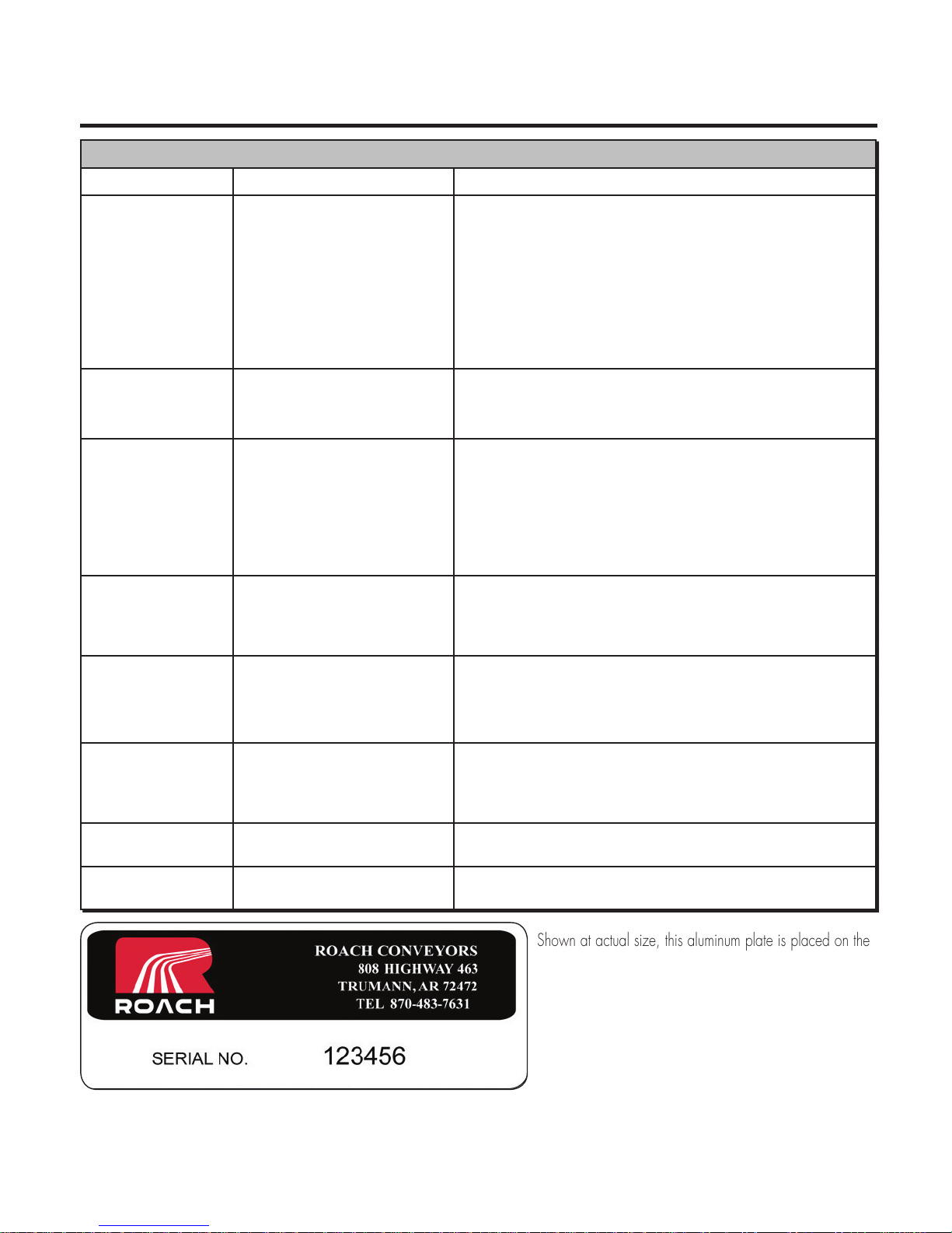
ORDERING REPLACEMENT PARTS
To order any replacement parts or when calling for assistance
with any powered conveyor, ALWAYS provide unit serial number.
Shown at actual size, this aluminum plate is placed on the
conveyor frame near the location of the drive assembly.
To order replacement parts or add-on components, contact
the Roach distributor who originally furnished the unit
if possible. If this is not possible, contact the National
Sales Office at 870-483-7631 for the name of the
authorized Roach distributor in your area. Have unit model
number and serial number BEFORE calling. Refer
to unit drawings (in rear section of handbook) for part numbers
if ordering replacement parts.
Page 16
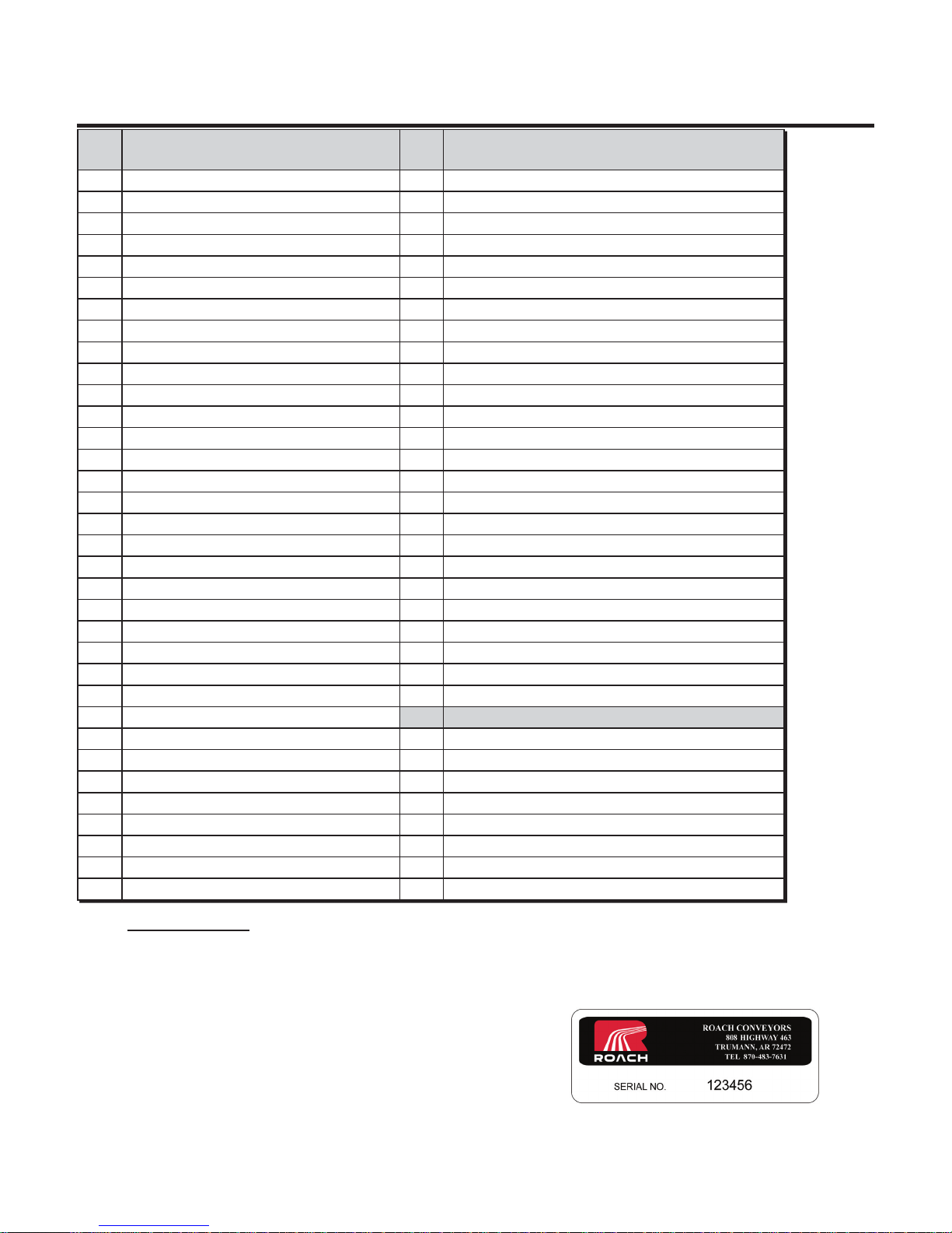
MODEL 138LRC
16
PARTS LIST FOR UNIT WITH END DRIVE / SIDE MOUNT END DRIVE
ITEM
#
1 138G roller w/5/16” shaft 35 5/16” flat washer
2 138T tapered roller 36 3/8” flange nut
3 138G grooved roller w/5/16” hex shaft 37 3/8” flat washer
4 Take-up sheave mounting channel 38 7/16” lock washer
5 45°/90° inside curve channel 39 1/2” hex nut
6 Splice plate 40 1/2” lock washer
7 Bolt-in butt coupling, left hand 41 1/2” flange nut
8 Bolt-in butt coupling, right hand 42 1/2” flat washer
9 Pillow block mounting bracket 43 Orange nylon finger guard
10 Take-up rod support angle 44 Black nylon sheave spacer/adapter
11 Sheave mounting channel 45 V-belt sheave w/1-3/16” bore
12 Idler sheave angle 46 Nylon 3” O.D. V-groove sheave
13 Left hand outside tangent drive channel 47 Steel 4” O.D. V-groove take-up sheave
14 Right hand outside tangent drive channel 48 V-belt
15 Left hand inside tangent side channel 49 Drive band
16 Right hand inside tangent side channel 50 Motor
17 Take-up mounting angle 51 Gear reducer
18 45°/90° outside curve channel 52 Drive sprocket
19 Tail sheave shaft 53 Gear reducer drive sprocket
20 Drive sheave shaft 54 #50 (thru 1-1/2 HP) ir #60 roller chain
21 Bed spacer rod 55 Chain guard angle mount (Not shown)
22 3 hole flange bearing w/1-3/16” bore 56 Reducer push plate assembly
23 Pillow block bearing w/1-3/16” bore 57 Underneath motor base plate
24 3/8” x 3/4” HHCS 58 End drive chain guard assembly
25 3/8” x 1-1/4” HHCS
26 3/8” x 1-1/2” HHCS OPTIONAL SIDE MOUNT END DRIVE PARTS LIST
27 3/8” x 1-3/4” HHCS 50 Motor
28 3/8” x 2-1/4” HHCS 51 Gear reducer
29 7/16” x 1” HHCS 52 Drive sprocket
30 1/2” x 1-1/2” HHCS 53 Gear reducer drive sprocket
31 1/2” x 6” HHTB 54 #50 (thru 1-1/2 HP) ir #60 roller chain
32 5/16” x 3/4” carriage bolt 55 Reducer push plate assembly
33 3/8” x 3/4” carriage bolt 56 Side mount motor base plate
34 5/16” flange nut 57 Side mount chain guard assembly
DESCRIPTION ITEM
#
DESCRIPTION
Specify Unit Serial Number when ordering replacement parts to ensure proper allocation of components (See Ordering
Replacement Parts on page 15).
Recommended Spare Parts are shown in red. Charted are item numbers and part descriptions. When
ordering use example below.
Example: Need a replacement 138T tapered roller for 138LRC
Part No: SN 123456 - 2 - 138T tapered roller
Page 17
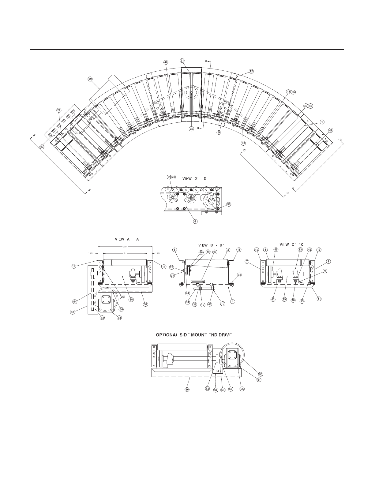
MODEL 138LRC
17
ILLUSTRATIONS FOR UNIT WITH END DRIVE / SIDE MOUNT END DRIVE
Page 18
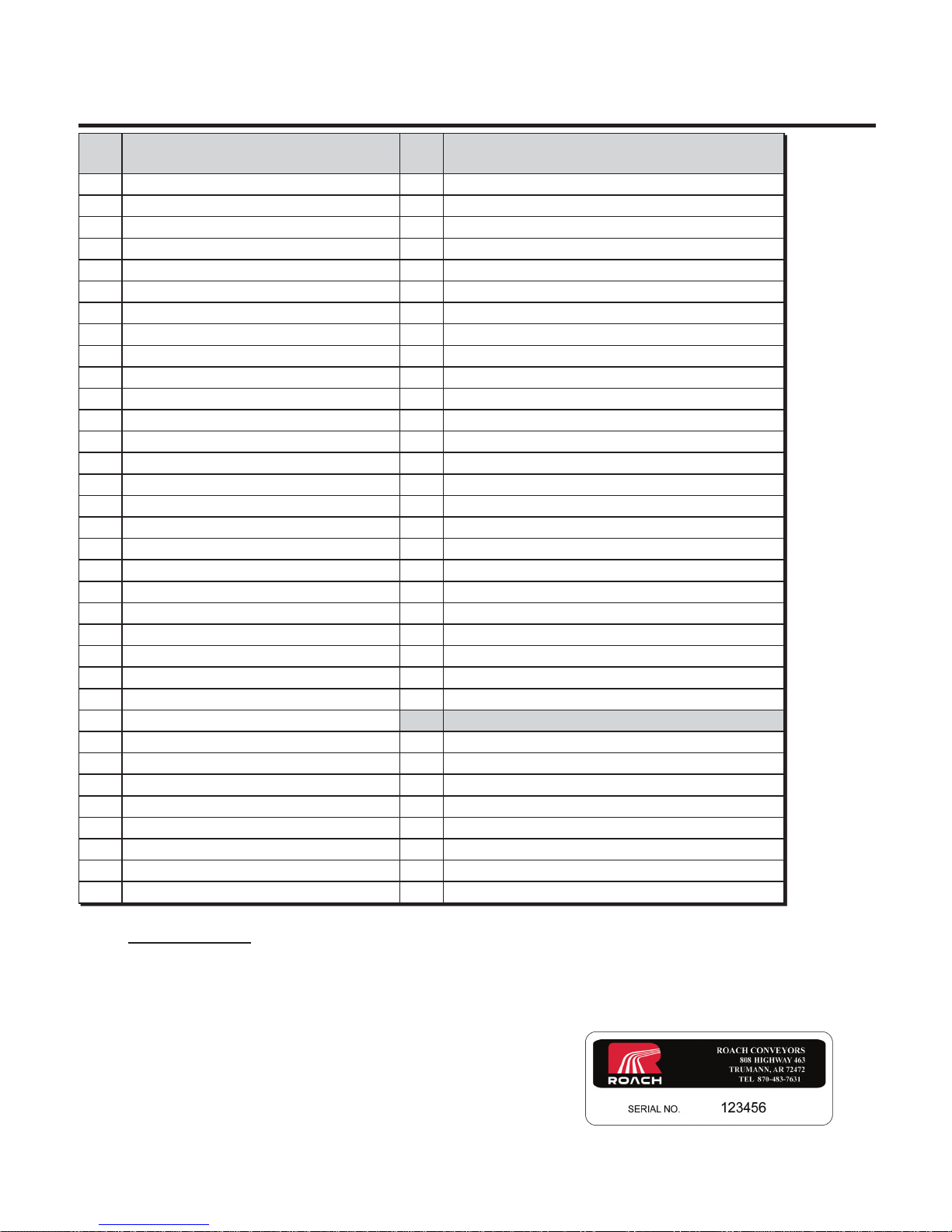
MODEL 196LRC
18
PARTS LIST FOR UNIT WITH END DRIVE / SIDE MOUNT END DRIVE
ITEM
#
1 196S roller 35 5/16” flat washer
2 254T tapered roller 36 3/8” flange nut
3 196S grooved roller 37 3/8” flat washer
4 Take-up sheave mounting channel 38 7/16” lock washer
5 45°/90° inside curve channel 39 1/2” hex nut
6 Splice plate 40 1/2” lock washer
7 Bolt-in butt coupling, left hand 41 1/2” flange nut
8 Bolt-in butt coupling, right hand 42 1/2” flat washer
9 Pillow block mounting bracket 43 Orange nylon finger guard
10 Take-up rod support angle 44 Black nylon sheave spacer/adapter
11 Sheave mounting channel 45 V-belt sheave w/1-3/16” bore
12 Idler sheave angle 46 Nylon 3” O.D. V-groove sheave
13 Left hand outside tangent drive channel 47 Steel 4” O.D. V-groove take-up sheave
14 Right hand outside tangent drive channel 48 V-belt
15 Left hand inside tangent side channel 49 1/8” Dia. x 9-1/2” lg.Drive band
16 Right hand inside tangent side channel 50 Motor
17 Take-up mounting angle 51 Gear reducer
18 45°/90° outside curve channel 52 Drive sprocket
19 Tail sheave shaft 53 Gear reducer drive sprocket
20 Drive sheave shaft 54 #50 (thru 1-1/2 HP) ir #60 roller chain
21 Bed spacer rod 55 Chain guard angle mount (Not shown)
22 3 hole flange bearing w/1-3/16” bore 56 Reducer push plate assembly
23 Pillow block bearing w/1-3/16” bore 57 Underneath motor base plate
24 3/8” x 3/4” HHCS 58 End drive chain guard assembly
25 3/8” x 1-1/4” HHCS
26 3/8” x 1-1/2” HHCS OPTIONAL SIDE MOUNT END DRIVE PARTS LIST
27 3/8” x 1-3/4” HHCS 50 Motor
28 3/8” x 2-1/4” HHCS 51 Gear reducer
29 7/16” x 1” HHCS 52 Drive sprocket
30 1/2” x 1-1/2” HHCS 53 Gear reducer drive sprocket
31 1/2” x 6” HHTB 54 #50 (thru 1-1/2 HP) ir #60 roller chain
32 5/16” x 3/4” carriage bolt 55 Reducer push plate assembly
33 3/8” x 3/4” carriage bolt 56 Side mount motor base plate
34 5/16” flange nut 57 Side mount chain guard assembly
DESCRIPTION ITEM
#
DESCRIPTION
Specify Unit Serial Number when ordering replacement parts to ensure proper allocation of components (See Ordering
Replacement Parts on page 15).
Recommended Spare Parts are shown in red. Charted are item numbers and part descriptions.
When ordering use example below.
Example: Need a replacement 254T tapered roller for 196LRC
Part No: SN 123456 - 2 - 254T tapered roller
Page 19
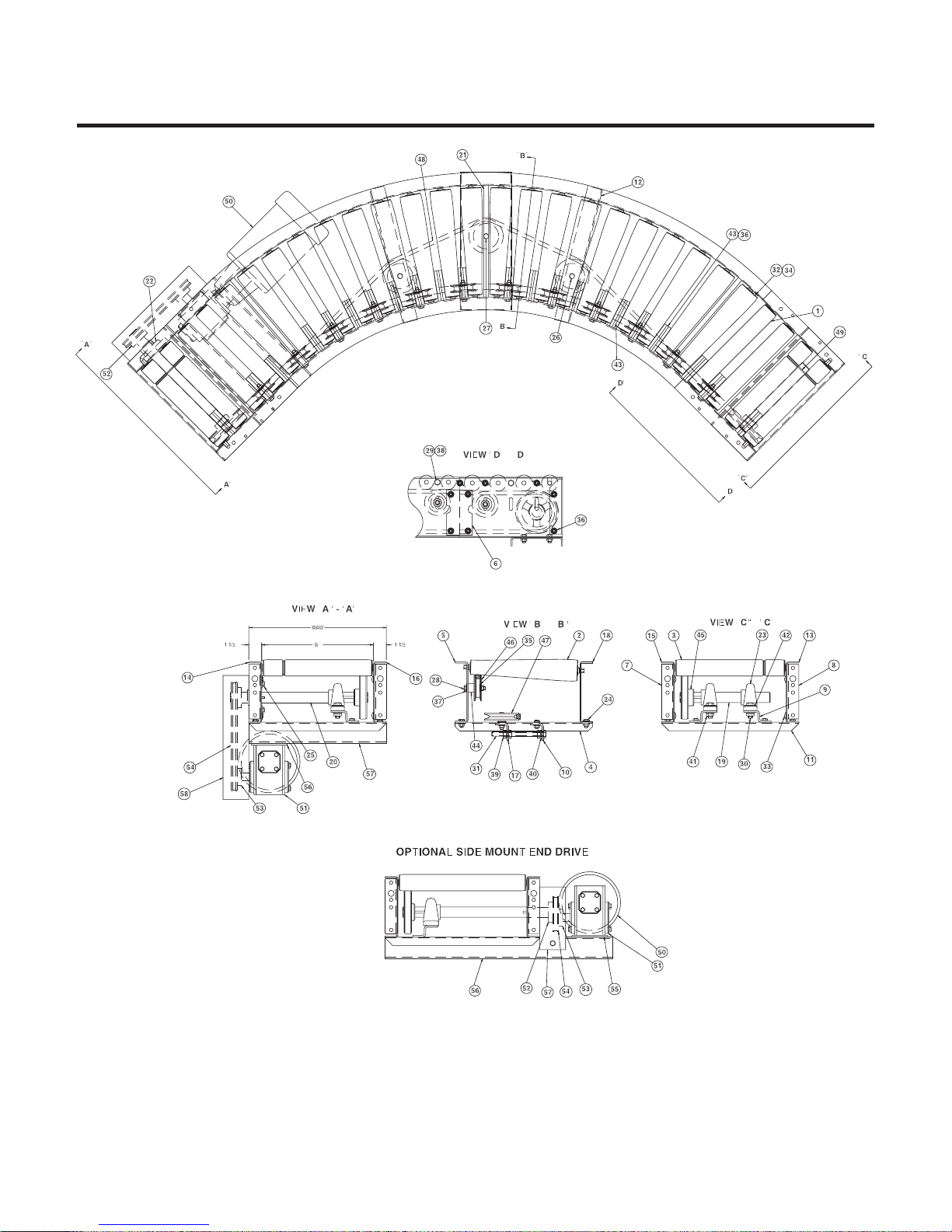
MODEL 196LRC
19
ILLUSTRATIONS FOR UNIT WITH END DRIVE / SIDE MOUNT END DRIVE
Page 20
MODEL 138LRCS
20
PARTS LIST FOR UNIT WITH END DRIVE / SIDE MOUNT END DRIVE
ITEM
#
1 138G roller w/5/16” hex (shortened for spur) 38 5/16” flange nut
2 138G roller w/5/16” hex 39 5/16” flat washer
3 138T tapered roller 40 3/8” flange nut
4 Spur assembly (specify 30° or 40°) 41 3/8” flat washer
5 138G grooved roller 42 7/16” lock washer
6 138G pinned roller w/5/16” hex (shortened for spur) 43 1/2” hex nut
7 Take-up sheave mounting channel 44 1/2” lock washer
8 Splice plate 45 1/2” flange nut
9 Bolt-in butt coupling (left hand) 46 1/8” x 1” cotter pin
10 Bolt-in butt coupling (right hand) 47 1/2” flat washer
11 Pillow block mounting bracket 48 Orange nylon finger guard
12 Take-up rod support angle 49 Black nylon sheave spacer/adaptor
13 Sheave mounting channel 50 V-belt sheave w/1-3/16” bore
14 Flange bearing mount 51 Flat idler sheave
15 Spur mounting bracket 52 Nylon 3” O.D. V-groove take-up sheave
16 32-1/2” IR inside curve channel 45°/60° 53 Steel 4” O.D, V-groove take-up sheave
17 Idler sheave angle 54 V-Belt
18 Outside tangent drive side channel 55 Drive band
19 Inside tangent side channel 56 Motor
20 Take-up mounting angle 57 Gear reducer
21 32-1/2” IR outside curve channel 45°/60° 58 Drive sprocket
22 Roller mounting clip 59 Gear reducer drive sprocket
23 Drive sheave shaft 60 #50 (thru 1-1/2 HP) or #60 roller chain
24 Tail sheave shaft 61 Chain guard angle mount (not shown)
25 Bed spacer rod 62 Reducer push plate assembly
26 3 hole flange bearing w/1/3/16” bore 63 Underneath motor base plate
27 Pillow block bearing w/1-3/16” bore 64 End Drive Chain Guard Assembly
28 3/8” x 3/4” HHCS
29 3/8” X 1-1/4” HHCS OPTIONAL SIDE MOUNT END DRIVE PARTS LIST
30 3/8” X 1-1/2” HHCS 56 Motor
31 3/8” X 1-3/4” HHCS 57 Gear reducer
32 3/8” X 2-1/4’ HHCS 58 Drive sprocket
33 7/16” X 1” HHCS 59 Gear reducer drive sprocket
34 1/2” X 1-1/2” HHCS 60 #50 (thru 1-1/2 HP) or #60 roller chain
35 1/2” X 6” HHTB 61 Reducer push plate assembly
36 5/16” X 3/4” carriage bolt 62 Side mount motor base plate
37 3/8” X 3/4” carriage bolt 63 Side mount chain guard assembly
DESCRIPTION ITEM
#
DESCRIPTION
Specify Unit Serial Number when ordering replacement parts to ensure proper allocation of components (See Ordering
Replacement Parts on page 15).
Recommended Spare Parts are shown in red. Charted are item numbers and part descriptions. When
ordering use example below.
Example: Need a replacement 138T tapered roller for 138LRCS
Part No: SN 123456 - 3 - 138T tapered roller
Page 21
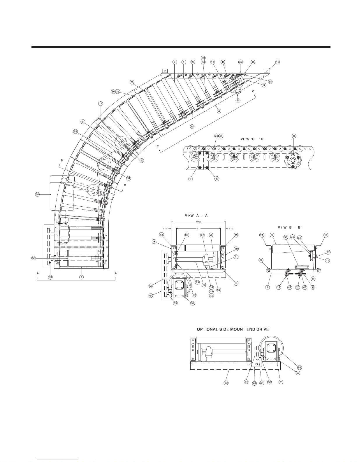
MODEL 138LRCS
21
ILLUSTRATIONS FOR UNIT WITH END DRIVE / SIDE MOUNT END DRIVE
Page 22

MODEL 196LRCS
22
PARTS LIST FOR UNIT WITH END DRIVE / SIDE MOUNT END DRIVE
ITEM
#
1 196S roller (shortened for spur) 38 5/16” flange nut
2 196S roller 39 5/16” flat washer
3 254T tapered roller 40 3/8” flange nut
4 Spur assembly (specify 30° or 40°) 41 3/8” flat washer
5 196S grooved roller 42 7/16” lock washer
6 196S pinned roller (shortened for spur) 43 1/2” hex nut
7 Take-up sheave mounting channel 44 1/2” lock washer
8 Splice plate 45 1/2” flange nut
9 Bolt-in butt coupling (left hand) 46 1/8” x 1” cotter pin
10 Bolt-in butt coupling (right hand) 47 1/2” flat washer
11 Pillow block mounting bracket 48 Orange nylon finger guard
12 Take-up rod support angle 49 Black nylon sheave spacer/adaptor
13 Sheave mounting channel 50 V-belt sheave w/1-3/16” bore
14 Flange bearing mount 51 Flat idler sheave
15 Spur mounting bracket 52 Nylon 3” O.D. V-groove take-up sheave
16 32-1/2”/48” IR inside curve channel 45°/60° 53 Steel 4” O.D, V-groove take-up sheave
17 Idler sheave angle 54 V-Belt
18 Outside tangent drive side channel 55 1/8” Dia. x 9-1/2” lg. Drive band
19 Inside tangent side channel 56 Motor
20 Take-up mounting angle 57 Gear reducer
21 32-1/2”/48” IR outside curve channel 45°/60° 58 Drive sprocket
22 Roller mounting clip 59 Gear reducer drive sprocket
23 Drive sheave shaft 60 #50 (thru 1-1/2 HP) or #60 roller chain
24 Tail sheave shaft 61 Chain guard angle mount (not shown)
25 Bed spacer rod 62 Reducer push plate assembly
26 3 hole flange bearing w/1/3/16” bore 63 Underneath motor base plate
27 Pillow block bearing w/1-3/16” bore 64 End Drive Chain Guard Assembly
28 3/8” x 3/4” HHCS
29 3/8” X 1-1/4” HHCS OPTIONAL SIDE MOUNT END DRIVE PARTS LIST
30 3/8” X 1-1/2” HHCS 56 Motor
31 3/8” X 1-3/4” HHCS 57 Gear reducer
32 3/8” X 2-1/4’ HHCS 58 Drive sprocket
33 7/16” X 1” HHCS 59 Gear reducer drive sprocket
34 1/2” X 1-1/2” HHCS 60 #50 (thru 1-1/2 HP) or #60 roller chain
35 1/2” X 6” HHTB 61 Reducer push plate assembly
36 5/16” X 3/4” carriage bolt 62 Side mount motor base plate
37 3/8” X 3/4” carriage bolt 63 Side mount chain guard assembly
DESCRIPTION ITEM
#
DESCRIPTION
Specify Unit Serial Number when ordering replacement parts to ensure proper allocation of components (See Ordering
Replacement Parts on page 15).
Recommended Spare Parts are shown in red. Charted are item numbers and part descriptions. When
ordering use example below.
Example: Need a replacement 138T tapered roller for 196LRCS
Part No: SN 123456 - 3 - 254T tapered roller
Page 23
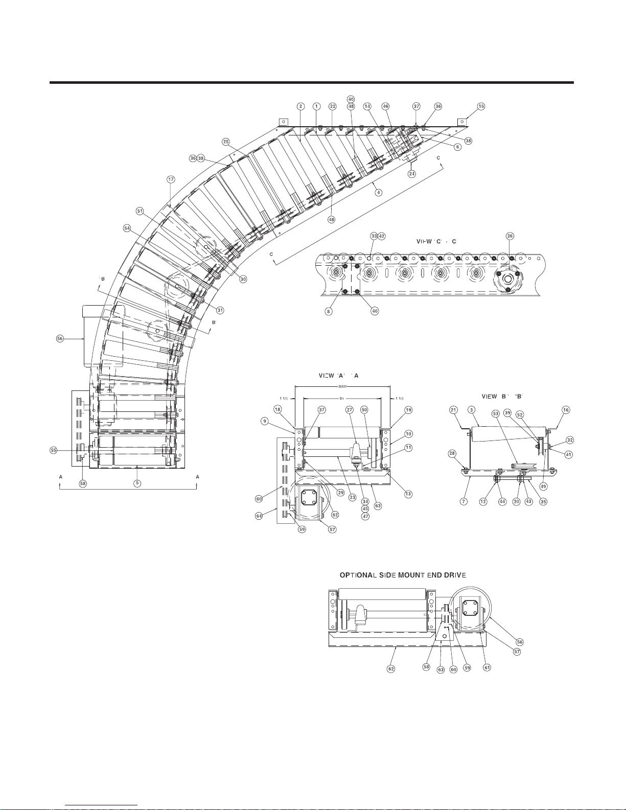
MODEL 196LRCS
23
ILLUSTRATIONS FOR UNIT WITH END DRIVE / SIDE MOUNT END DRIVE
Page 24

Roach conveyoRs
WaRRanty
• MaterialsusedbyRoachConveyorsareofgoodquality.
• AnypartprovingtobedefectiveinmaterialsorworkmanshipuponRoachinspec-
tion, will be replaced at NO cost, FOB, Trumann, Arkansas, for one year. Installation
expense will be paid by others.
• Roachliabilityincludesfurnishingsaidpartorparts;Roachisnotliableforconsequential damages, such as loss of profit, delays or expenses incurred by failure of said part
or parts.
• Failureduetoabuse,incorrectadjustments,exposuretocorrosiveorabrasiveenvironment or operation under damp conditions does not constitute failure due to defects in
workmanship or materials.
• ComponentpartsnotmanufacturedbyRoach(motors,gearreducers,etc.)will
be repaired or replaced at the option of their manufacturer. Contact nearest
authorized service center for all warranty claims.
NOTE: Motors or gear reducers tampered with before inspection shall be considered free of ALL Warranty Claims.
--All specifications are subject to change without notice--
--Drawings are intended for illustration ONLY and are not to scale--
Tel 870-483-7631 Fax 870-483-7049
ROACH CONVEYORS
808 HIGHWAY 463 NORTH
TRUMANN, ARKANSAS 72472-1310
www.roachconveyors.com
MCW06622-18
05-2007
 Loading...