


Metal Oxide Film Resistors
Axial Connections
Metal Oxide Film Resistors 1/2W, 5% Components
High safety standard, high purity ceramic core
Excellent non-ame coang
Stable performance in diverse environment, meet EIAJ-RC2655A requirements
Too low or too high ohmic value can be supplied on a case to case basis
Solderability: 95%
Temperature Cycling: ±(2.0% +0.05Ω) Max, with no evidence of mechanical damage
Original package: 5000 pcs
D Max. 3.5 mm
L Max. 10 mm
PT 52 mm
SPECIFICATION:
Rated output 0.5 W
Tolerance ±5 %
Temperature coecient 350 ppm/°C
Rated voltage 400 V
Housing type Axial
PRODUCT RANGE:
Art. Nr. Resistance
RND 155MOR0W2J0101A10 100 Ω
RND 155MOR0W2J0102A10 1 kΩ
RND 155MOR0W2J010JA10 1 Ω
RND 155MOR0W2J0153A10 1.5 kΩ
RND 155MOR0W2J0182A10 1.8 kΩ
RND 155MOR0W2J0221A10 220 Ω
RND 155MOR0W2J0224A10 220 kΩ
RND 155MOR0W2J022JA10 2.2 Ω
RND 155MOR0W2J0333A10 33 kΩ
RND 155MOR0W2J0334A10 330 kΩ
RND 155MOR0W2J043JA10 4.3 Ω
RND 155MOR0W2J0473A10 47 Ω
RND 155MOR0W2J047JA10 4.7 Ω
RND 155MOR0W2J047KA10 0.47 Ω
RND 155MOR0W2J0503A10 50 kΩ
RND 155MOR0W2J050KA10 0.5 Ω
RND 155MOR0W2J0513A10 51 kΩ
RND 155MOR0W2J062KA10 0.62 Ω
RND 155MOR0W2J0680A10 68 Ω
RND 155MOR0W2J0682A10 6.8 kΩ
Distrelec Group AG, Grabenstrasse 6, 8606 Nänikon, Switzerland, T +41 44 944 99 11, info@distrelec.com, distrelec.com

1. Scope:
g
g
This specification for approval relates to Metal Oxide Film Fixed Resistors manufactured by
ROYALOHM 's specifications.
2. Type designation:
The type designation shall be in the following form :
(Ex.)
MOR 1/4W J 100Ω
Type Power Rating Resistance Nominal
3. Ratings:
Ratings shall be shown in the table 1.
Type
MO-25 0.25W 250 V 400 V 250 V
MO-50 0.50 W 250 V 400 V 250 V
MO-100 1 W 350 V 600 V 350 V
Normal
size
Small
size
MO-200 2 W 350 V 600 V 350 V
MO-300 3 W 500 V 800 V 500 V 5Ω--100KΩ
MO-500 5 W 750 V 1,000 V 750 V 5Ω--150KΩ
MO-700 7 W 750 V 1,000 V 750 V 20Ω--150KΩ
MO-800 8 W 750 V 1,000 V 750 V 30Ω--200KΩ
MO-900 9 W 750 V 1,000 V 750 V 50Ω--200KΩ
MO-50-S 0.50 W 250 V 400 V 250 V
MO-100-S 1 W 350 V 600 V 350 V
MO-200-S 2 W 350 V 600 V 350 V
MO-300-S 3 W 350 V 600 V 350 V
MO-500-SS 5 W 500 V 800 V 500 V 5Ω--100KΩ
MO-500-S 5 W 500 V 800 V 500 V 5Ω--150KΩ
Rated
Power
at 70℃
Table 1
Max.
Working
Volta
e
Max.
Overload
e
Volta
Tolerance Resistance
Dielectric
Withstanding
Resistance
Range
0.3--50K
0.3--50K
0.3--50K
0.3--50K
0.3--50K
0.3--50K
0.3--50K
0.3--50K
Operating Temp.
Range
-55℃ -- +155℃
3.1 Power rating:
Resistors shall have a power rating based on continuous full load operation at an
ambient temperature of 70 ℃. For temperature in excess of 70 ℃ , the load shall be
derated as shown in the figure 1.
3.2 Voltage rating:
Resistors shall have a rated direct-current (DC) continuous working voltage or an approximate
sine-wave root-mean-square (RMS) alternating-current (AC) continuous working voltage at commercialline frequency and waveform corresponding to the power rating , as determined from the
following formula :
RCWV = √P x R
Were : RCWV = Rated DC or RMS AC continuous working voltage at commercial-line frequency and
waveform (volt)
P = Power Rating (watt)
R = Nominal Resistance (ohm)
Page 1. 2017/02/08--Version 1.

Metal Oxide Film Fixed Resistors
In no case shall the rated DC or RMS AC continuous working voltage be greater
than the applicable maximum value.
Figure 1.
3.3 Nominal resistance :
Effective figures of nominal resistance shall be in accordance with E-24
series, and resistance tolerance shall be shown by table 1.
4. Construction :
No.
1 Basic Body Rod Type Ceramics
2 Resistance Film 0.1Ω ≤ R ≤ 12Ω : CNP film
Name Material
10Ω ≤ R ≤ 100kΩ : Metal oxide film
R > 100kΩ : Carbon film
3 End Cap Steel (Tin plated iron surface)
4 Lead Wire Annealed copper wire coated with tin
5 Joint By welding
Normal size:
6 Coating
7 Color Code Non-Flame epoxy resin
--Insulated & Non-Flame Paint (Color : Gray )
Small size:
--Insulated & Non-Flame Paint (Color : Sea-Blue )
Page 2. 2017/02/08--Version 1.

5. Characteristics :
Metal Oxide Film Fixed Resistors
Characteristics Limits
Test Methods
( JIS C 5201-1 )
Must be within the specified 5.1 The limit of error of measuring apparatus
DC. Resistance tolerance. shall not exceed allowable range or 5% of
resistance tolerance
5.2 Natural resistance change per temp.
Resis.Range T.C.R. (PPM/℃)
Temperature 0.1Ω ~ 12Ω
coefficient 12.1Ω ~ 100K R
101K ~ 1M R
1.1M ~ 10M
±200
±350
-700
-1500
Resistance change rate is 5.5 Permanent resistance change after the
Short time
Normal Size : ± (1% + 0.05Ω) Max.
overload Small Size : ± (2% + 0.05Ω) Max. or the max. overload voltage respectively specified
degree centigrade.
R
2-R1
6
x 10
1(t2-t1)
1: Resistance value at room temperature (t1)
R
2: Resistance value at room temp. plus 100 ℃ (t2)
(PPM/℃)
application of a potential of 2.5 times RCWV
with no evidence of mechanical damage in the above list, whichever less for 5 seconds
Dielectric No evidence of flashover 5.7 Resistors shall be clamped in the trough
withstanding mechanical damage, arcing or of a 90° metallic V-block and shall be tested at
voltage insulation break down AC potential respectively specified in the table 1.
for 60 + 10/ -0 seconds
6.1 Direct load :
Resistance to a 2.5 kgs direct load for 10 secs.
in the direction of the longitudinal axis of the
terminal leads
Terminal With no evidence of mechanical
Twist test :
strength damage Terminal leads shall be bent through 90 ° at
point of about 6mm from the body of the
resistor and shall be rotated through 360°
about the original axis of the bent terminal in
alternating direction for a total of 3 rotations
2017/02/08--Version 1.

Metal Oxide Film Fixed Resistors
Characteristics Limits
Test Methods
( JIS C 5201-1 )
Resistance change rate is 6.4 Permanent resistance change when leads
Resistance to
soldering heat evidence of mechanical damage
Solderability 95 % coverage Min. from concentrated pinholes.
Resistance to No deterioration of protective trichroethane completely for 3 minutes with
solvent coatings and markings ultrasonic
Temperature Resistance change rate is
cycling
± (1% + 0.05Ω) Max. with no
± (2% + 0.05Ω) Max.
with no evidence of mechanical 2 Room temp.
damage 3
immersed to 3.2 mm to 4.8 mm from the body
in 350℃ ± 10 ℃ solder for 3 ± 0.5 seconds
6.5 The area covered with a new , smooth
clean , shiny and continuous surface free
Test temp. of solder : 245℃ ± 3℃
Dwell time in solder : 2 ~ 3 seconds
6.9 Specimens shall be immersed in a bath of
7.4 Resistance change after continuous
5 cycles for duty shown below:
Step
1
4 Room temp.
Temperature Time
-55℃ ± 3℃
+155℃ ± 2℃
30 mins
10~15 mins
30 mins
10~15 mins
7.9 Resistance change after 1,000 hours
Load life in
humidity
Load life
Pulse overload Normal Size : ± (2% + 0.05Ω) Max. (1 second "on", 25 seconds "off" ) at 4 times
Resistance value
Less than 100KΩ
100KΩ or more test chamber controlled at 40 ℃ ± 2 ℃
Resistance value
Less than 100KΩ
100KΩ or more 70℃ ± 2℃ ambient
Resistance change rate is 5.8 Resistance change after 10,000 cycles
Small Size : ± (5% + 0.05Ω) Max. with no
evidence of mechanical damage RCWV or the max. pulse overload voltage
△R/R
± 5 %
± 10 %
△R/R
± 5 %
± 10 %
operating at RCWV with duty cycle of
(1.5 hours "on", 0.5 hour "off") in a humidity
and 90 to 95 % relative humidity
7.10 Permanent resistance change after
1,000 hours operating at RCWV with duty
cycle of (1.5 hours "on", 0.5 hour "off") at
Page 4. 2017/02/08--Version 1.

Metal Oxide Film Fixed Resistors
6. Dimension : Unit : mm
Normal size
Part No. Style
MOR0W4 MOR-25 1/4W (0.25W) 2.5 7.5 0.54 28
MOR0W2 MOR-50 1/2W (0.50W) 3.5 10 0.54 28
MOR01W MOR-100 1W 5 12 0.70 25
MOR02W MOR-200 2W 5.5 16 0.70 28
MOR03W MOR-300 3W 6.5 17.5 0.75 28
Power Rating at
70 ℃
D (Max.) L (Max.) H ± 3
Dimension (mm)
d ± 0.05
MOR05W MOR-500 5W 8.5 26 0.75 38
MOR07W MOR-700 7W 8.5 32 0.75 38
MOR08W MOR-800 8W 8.5 41 0.75 38
MOR09W MOR-900 9W 8.5 54 0.75 38
Small size
Part No. Style
MOR0S2 MOR-50-S 1/2W (0.50W) 2.5 7.5 0.54 28
MOR01S MOR-100-S 1W 3.5 10 0.54 28
MOR02S MOR-200-S 2W 5 12 0.70 25
MOR03S MOR-300-S 3W 5.5 16 0.70 28
MOR05U MOR-500-SS 5W 6.5 17.5 0.75 28
MOR05S MOR-500-S 5W 8 25 0.75 38
Power Rating at
70 ℃
D (Max.) L (Max.) H ± 3
Dimension (mm)
d ± 0.05
Painting method:
Welding point, terminal and lead wire, is permissible to be exposed without the outer coated cover.
The extent should be within 1/2 of the are angle.
2017/02/08--Version 1.

Metal Oxide Film Fixed Resistors
7. Marking :
7.1 For MO 1/4W, 1/2W, 1W, 2W, 3W, 5W and all of small size
Resistors shall be marked with color coding
colors shall be in accordance with JIS C 0802
7.2 For MO 7W, 8W, 9W
Code description and regulation
1. Wattage rating.
Nominal resistance value.
2.
3. Resistance Tolerance.
G : ± 2 %
J
: ± 5 %
K : ± 10 %
7.3 Label :
Label shall be marked with following items:
(1) Type and style
(2) Nominal resistance
(3) Resistance tolerance
(4) Quantity
(5) Lot number
(6) PPM
Example :
Metal Oxide Film Fixed Resistors
Watt : 1/4W Val : 100R
Q'TY : 5,000 Tol : 5%
Lot : 702312 PPM :
ROYALOHM
Pb Free
2017/02/08--Version 1.
Metal Oxide Film Fixed Resistors
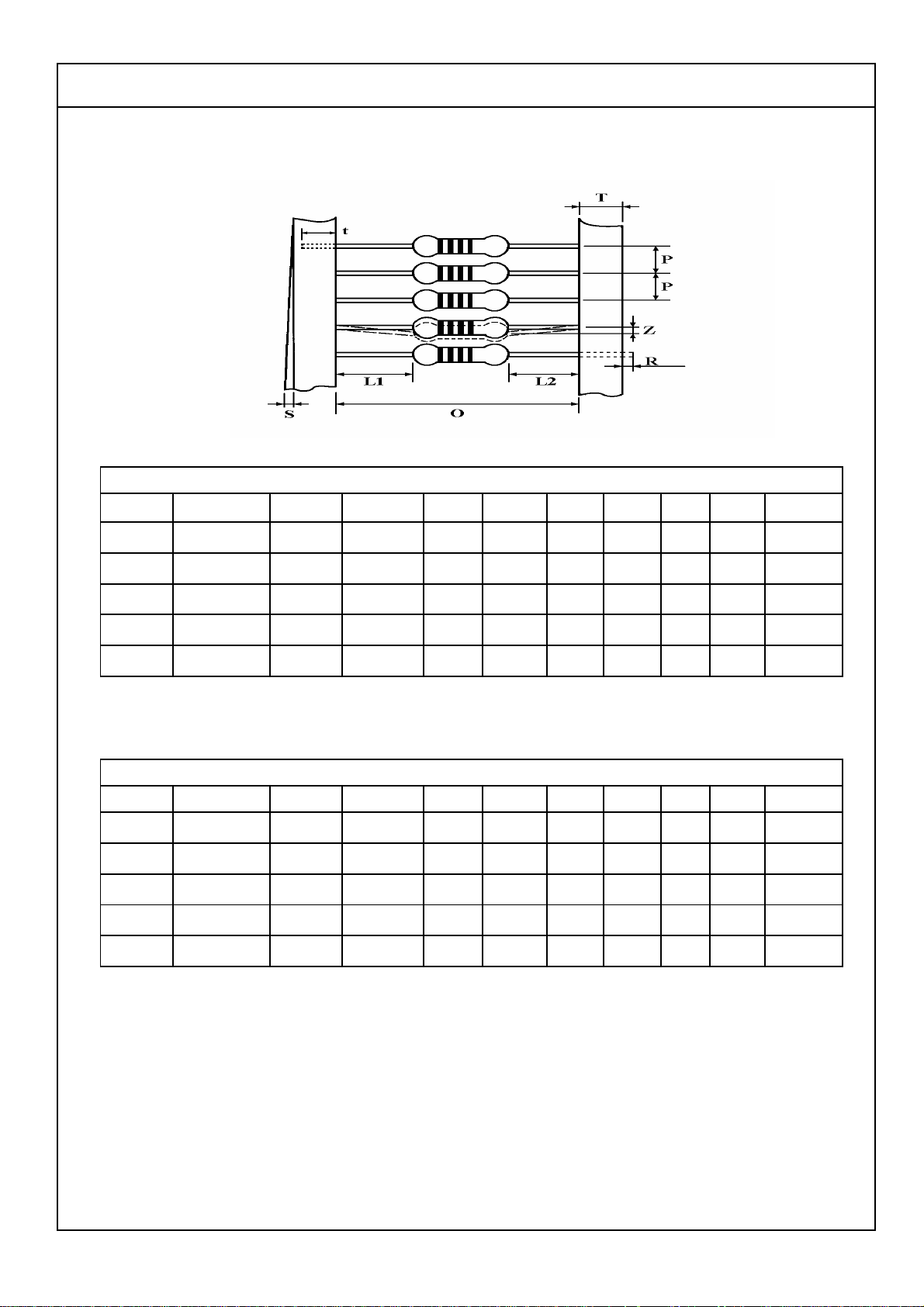
8. Packing specification :
8.1 Taping dimension :
Dimensions (mm)
Normal size
Part No. Style Style O P L1-L2 T Z R t S
MOR0W4 MOR-25 PT-52 52 ± 1 5 ± 0.3 1 Max. 6 ± 1 1 Max. 0 4 ± 1 0.5 Max.
MOR0W2 MOR-50 PT-52 52 ± 1 5 ± 0.3 1 Max. 6 ± 1 1 Max. 0 4 ± 1 0.5 Max.
MOR01W MOR-100 PT-52 52 ± 1 5 ± 0.3 1 Max. 6 ± 1 1 Max. 0 4 ± 1 0.5 Max.
MOR02W MOR-200 PT-64 64 ± 1 10 ± 0.5 1 Max. 6 ± 1 1 Max. 0 5 ± 1 0.5 Max.
MOR03W MOR-300 PT-64 64 ± 1 10 ± 0.5 1 Max. 6 ± 1 1 Max. 0 5 ± 1 0.5 Max.
Small size
Part No. Style Style O P L1-L2 T Z R t S
MOR0S2 MOR-50-S PT-52 52 ± 1 5 ± 0.3 1 Max. 6 ± 1 1 Max. 0 4 ± 1 0.5 Max.
MOR01S MOR-100-S PT-52 52 ± 1 5 ± 0.3 1 Max. 6 ± 1 1 Max. 0 4 ± 1 0.5 Max.
MOR02S MOR-200-S PT-52 52 ± 1 5 ± 0.3 1 Max. 6 ± 1 1 Max. 0 4 ± 1 0.5 Max.
MOR03S MOR-300-S PT-64 64 ± 1 10 ± 0.5 1 Max. 6 ± 1 1 Max. 0 5 ± 1 0.5 Max.
MOR05U MOR-500-SS PT-64 64 ± 1 10 ± 0.5 1 Max. 6 ± 1 1 Max. 0 5 ± 1 0.5 Max.
2017/02/08--Version 1.

8.2 Tape in box packing :
Dimension (mm)
Metal Oxide Film Fixed Resistors
Bandoliers may also be
contained in a cardboard
box ("Ammopack")
Part No. Style Style
MOR0W4 MOR-25 PT-52 250 75 96 5,000
MOR0W2 MOR-50 PT-52 260 85 70 1,000
MOR01W MOR-100 PT-52 262 86 80 1,000
MOR02W MOR-200 PT-64 262 92 108 1,000
MOR03W MOR-300 PT-64 256 92 80 500
Part No.
MOR0S2 MOR-50-S PT-52 250 75 96 5,000
MOR01S MOR-100-S PT-52 260 85 70 1,000
MOR02S MOR-200-S PT-52 262 86 80 1,000
MOR03S MOR-300-S PT-64 262 92 108 1,000
Style
Style
L (C) W (A) H (B)
±5 ±5 ±5
L (C) W (A) H (B)
±5 ±5 ±5
Quantity Per
Box (pcs.)
Quantity Per
Box (pcs.)
MOR05U MOR-500-SS PT-64 256 92 80 500
"Ammopack" is an abbreviation of "ammunition pack"
2017/02/08--Version 1.
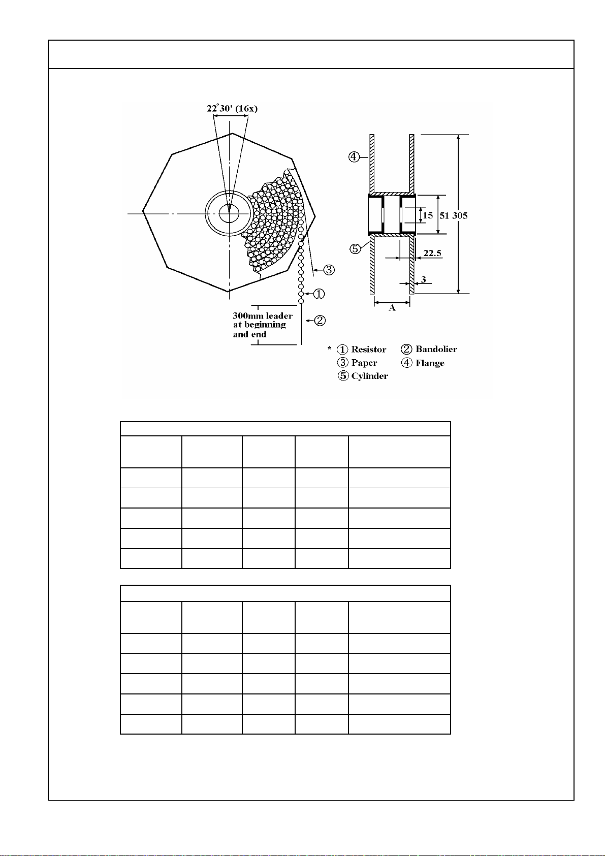
8.3 Tape on reel packing :
Metal Oxide Film Fixed Resistors
Dimension (mm) :
Normal size
Part No. Type
MOR0W4 MOR-25 PT-52 73 ± 2 5,000
MOR0W2 MOR-50 PT-52 73 ± 2 2,500
MOR01W MOR-100 PT-52 73 ± 2 2,500
MOR02W MOR-200 PT-64 81 ± 5 1,000
MOR03W MOR-300 PT-64 81 ± 5 500
Style
Across
Flange (A)
Quantity Per Reel
Small size
Part No. Type
MOR0S2 MOR-50-S PT-52 73 ± 2 5,000
MOR01S MOR-100-S PT-52 73 ± 2 2,500
MOR02S MOR-200-S PT-52 73 ± 2 2,500
MOR03S MOR-300-S PT-64 81 ± 5 1,000
Style
Across
Flange (A)
Quantity Per Reel
MOR05U MOR-500-SS PT-64 81 ± 5 500
2017/02/08--Version 1.

Metal Oxide Film Fixed Resistors
8.4 Bulk in inner box packing ( in plastic bag )
Inner Box of Plastic bag.
Dimension : Unit : mm
Q'ty /
Part No.
MOR07W MOR-700 8 32 3,200 150 x 75 x 33 392 x 515 x 283 18
MOR08W MOR-800 10 300 1,800 200 x 171 x 113 520 x 215 x 250 13
MOR09W MOR-900 10 300 1,800 200 x 171 x 113 520 x 215 x 250 15
Type
Q'ty /
Bag (pcs.)
Inner
Box
(pcs.)
Q'ty /
Carton
(pcs.)
Inner Box Size
L x W x H (±5)
Carton Box
Carton Box Size
L x W x H (±5)
Gross Wt.
± 2 Kgs.
2017/02/08--Version 1.
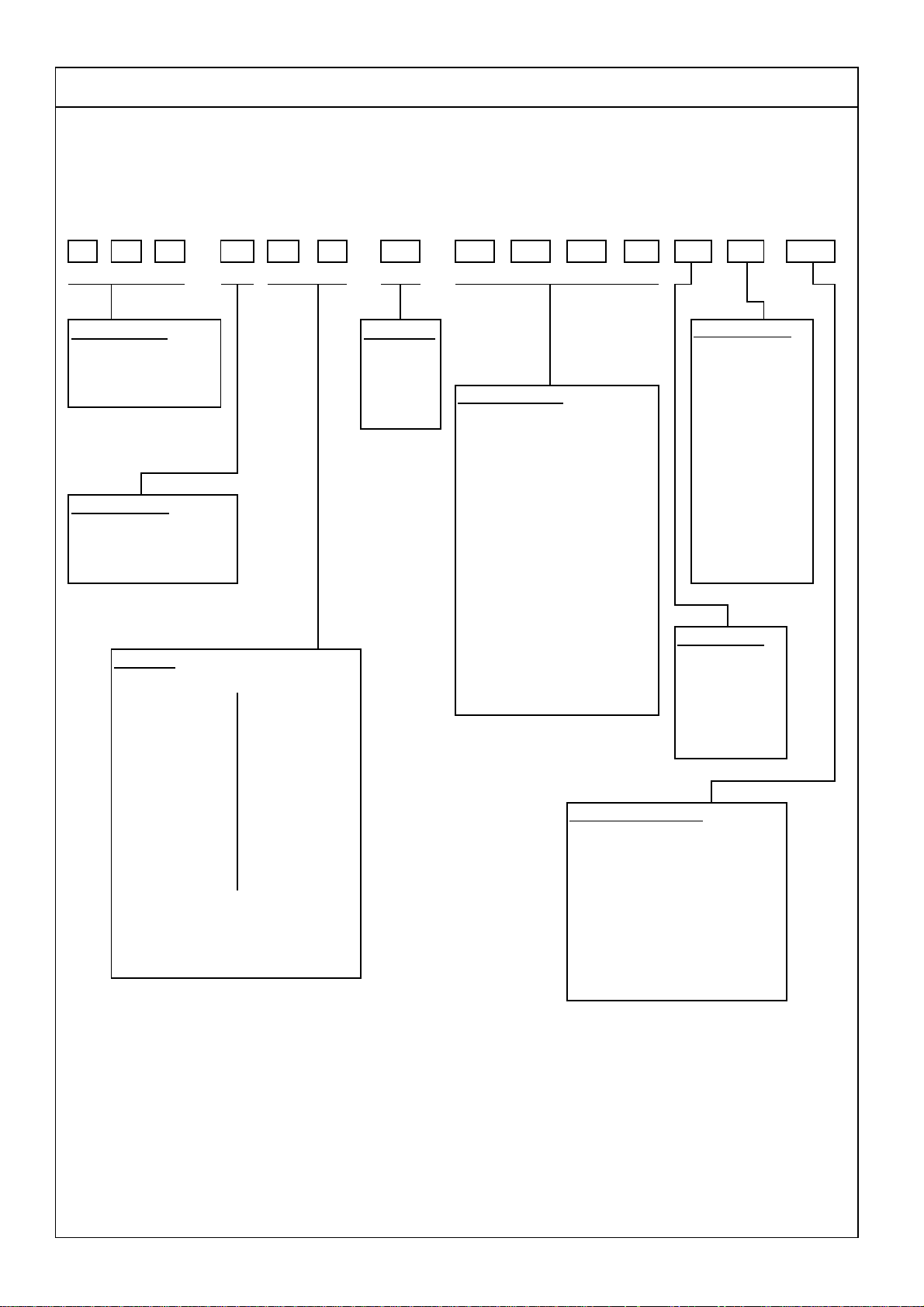
Part Number System
Explanation of Part Number System
(Metal Oxide Film Fixed Resistors)
123 5 6 11
MO R W 4 1
Product Type: Tolerance:
MOR = Metal Oxide Film
Fixed Resistor
Special Feature:
0 = Standard Product "J" ~ 0.1, "K" ~ 0.01 D = 20,000pcs
I = Non-Inductive Product
Wattage:
Normal size: Small size:
W4 = 1/4W S2 = 1/2W-S
W2 = 1/2W 1S = 1W-S
1W = 1W 2S = 2W-S
4 7 8 9 10 12 13
0 J 010 A5 0
Packing Quantity:
F ~ ± 1%
G ~ ± 2%
J ~ ± 5%
K ~ ± 10%
Resistance Value:
E-24 series: the 1
E--96 Series: the 1
nd
the 2
the significant figures of the A = 500pcs
resistance and the 4
the number of zeros following: C = 10,000pcs
Ex.: 4.7Ω ~ 47J, 4.7KΩ ~ 472
are significant figures of
resistance and the fourth
one denotes number of zeros
following: A = Tape/Box
Ex.: 1.33KΩ = 1331
st
digit is"0",
& 3rd digits are for
th
indicate
st
to 3rd digits
1 = 1,000pcs
2 = 2,000pcs
3 = 3,000pcs
4 = 4,000pcs
5 = 5,000pcs
B = 2,500pcs
0 = for Bulk/Box
packing
Packing Type:
T = Tape/Reel
B = Bulk/Box
P = Tape/Box of
PT-26mm
2W = 2W 3S = 3W-S
3W = 3W 5S = 5W-S
5W = 5W
7W = 7W
8W = 8W
9W = 9W
Extra Small size:
5U = 5W-SS
Addition Information:
0 = PT-52mm, NIL for PT-26mm
8 = PT-58mm
9 = PT-64mm
7 = Lead wire(H) 38mm
A = PT-83mm
C = PT-73mm
D = PT-71mm
14
Sample:
MO 1/4W +/- 5% 100Ω T/B 5,000 PT-52mm → MOR0W4J0101A50
2017/02/08--Version 1.
Metal Oxide Film Fixed Resistors
Environment Related Substance
This product complies to EU RoHS directive, EU PAHs directive, EU PFOS directive and Halogen free.
Ozone layer depleting substances.
Ozone depleting substances are not used in our manufacturing process of this product.
This product is not manufactured using Chloro fluorocarbons (CFCs), Hydrochlorofluorocarbons (HCFCs),
Hydrobromofluorocarbons (HBFCs) or other ozone depleting substances in any phase of the manufacturing process.
Storage Condition
The performance of these products, including the solderability, is guaranteed for a year from the date
of arrival at your company, provided that they remain packed as they were when delivered and stored
at a temperature of 25°C ± 10°C and a relative humidity of 60%RH ± 10%RH, chemical and dust free atmosphere
Even within the above guarantee periods, do not store these products in the following conditions.
Otherwise, their electrical performance and/or solderability may be deteriorated, and the packaging materials
(e.g. taping materials) may be deformed or deteriorated, resulting in mounting failures.
1. In salty air or in air with a high concentration of corrosive gas, such as Cl
2. In direct sunlight
, H2S, NH3, SO2, or NO
2
2
2017/02/08--Version 1.
 Loading...