

RNA SRC-N 200-2, SRC-B 200-2, SRC-N 160-2, SRC-N 250-2, SRC-B 250-2 Installation And Operating Instructions Manual
...
Installation and Operating Instructions
Vibratory Feeders
SRC-N 160-2
SRC-N 200-2
SRC-B 200-2
SRC-N 250-2
SRC-B 250-2
SRC-N 400-1
SRC-N 400-2
SRC-N 630-1
SRC-N 800-1
SRHL 400-1
SRHL 400-2

Rhein-Nadel Automation GmbH 2
VT-MA-SRC 160-800-EN_2019 / 20.03.2019 SJ
Table of Contents
1. General .................................................................................................................................. 4
1.1. Technical data..................................................................................................................... 4
2. Safety directives ..................................................................................................................... 7
2.1. Applicable directives and standards .................................................................................... 8
3. Design and functional description .......................................................................................... 8
4. Shipment and installation ..................................................................................................... 10
5. Commissioning ..................................................................................................................... 12
5.1. Feeder speed decreases? ................................................................................................ 13
5.2. Feeder speed increases? ................................................................................................. 13
6. Maintenance ......................................................................................................................... 14
7. Spare parts and customer service ........................................................................................ 14
8. What if...Advice on troubleshooting ...................................................................................... 15

Rhein-Nadel Automation GmbH 3
VT-MA-SRC 160-800-EN_2019 / 20.03.2019 SJ
Declaration of Incorporation
According to the Low-Voltage Directive 2014/35/EU
We hereby declare that the product meets the following requirements:
Low-Voltage Directive 2014/35/EC
Applied harmonised standards: DIN EN 60204 T1
Remarks:
We assume that our product will be incorporated into a stationary machine.
.
Rhein-Nadel-Automation
--------------------------------Managing Director
Jack Grevenstein

Rhein-Nadel Automation GmbH 4
VT-MA-SRC 160-800-EN_2019 / 20.03.2019 SJ
1. General
1.1. Technical data
Vibratory feeder type1
SRC-N 160-2
SRC-N 200-2
SRC-B 200-2
SRC-N 250-2
SRC-B 250-2
SRC-N 400-1
Dimensions Ø x H (mm)
157 x 132.5
180 x 165
180 x 165
290 x 215
290 x 215
440 x 228
Weight
7 kg
11 kg
11 kg
40 kg
40
103
Degree of protection
IP 54
IP 54
IP 54
IP 54
IP 54
IP 54
Connecting cable length
1.4 m
1.4 m
1.4 m
0.5 m
0.5
0.5
Power input2 (VA)
110
240
240
519
519
753
Current 2 (A)
0.55
1.2
1.2
2.6
2.6
3.75
Nominal magnet voltage 2/
Frequency
200 V / 50 Hz
Number of magnets
1 1 1 3 3
3
Magnet type/
Article number
WZAW 040
35000714
WZUW 080
35000721
WZUW 080
35000721
WZAW 060
35000727
WZAW 060
35000727
YZAW 080
35000739
Magnet colour
black
black
black
black
black
red
Air gap (mm)
0.3 - 0.5
0.4 - 0.5
0.4 - 0.5
1 - 1.2
1 - 1.2
2.3 - 2.8
Vibration frequency (Hz-1)
100
100
100
100
100
50
Number of spring packs
3 3 3 3 3
3
Standard spring set
No. of springs per pack
3 x 4
3 x 4
3 x 4
1 x 4
2 x 3
3 x 6
3 x 6
1 set of
Spring dimensions
Length (borehole gauge) x
width
87 (67) x20
87 (67) x 20
87 (67) x 20
106 (86) x 35
106 (86) x 35
139 (116) x
40
Spring thickness (mm)
1 1 1.5 2 2
2
Property classes of spring
fastening bolts
8.8
8.8 8.8
8.8
8.8
8.8
Tightening torque of spring
fastening bolts
25 Nm
25 Nm
25 Nm
100 Nm
100 Nm
100 Nm
Max. weight of vibrating
units, depending on mass
moment of inertia and desired feeder speed
2.5 kg
3.5 kg
3.5 kg
13 kg
13 kg
35 kg

Rhein-Nadel Automation GmbH 5
VT-MA-SRC 160-800-EN_2019 / 20.03.2019 SJ
1
The last digit of the type designation indicates the vibration frequency: 1=50 Hz, 2=100 Hz
2
For special connected loads (voltage / frequency) see rating plate on the magnet
Notice
All vibratory feeders listed in this table shall be operated only in conjunction with an RNA controller and with
a mains voltage of 230 V / 50 Hz. For special voltages and frequencies please refer to the separate data
sheet.
Vibratory feeder type1
SRC-N 400-2
SRHL 400-1
SRHL 400-2
SRC-N 630-1
SRC-N 800-1
Dimensions Ø x H (mm)
440 x 228
470 x 249
470 x 249
660 x 225
805 x 315
Weight
103
140
140
168
270
Degree of protection
IP 54
IP 54
IP 54
IP 54
IP 54
Connecting cable length
0.5
0.5
0.5
0.5
1.4
Power input2 (VA)
786
1140
1060
1000
1700
Current 2 (A)
4.05
5.7
5.3 5 8.5
Nominal magnet voltage 2 /
frequency
220V / 50Hz
Number of magnets
3 2 2 4 4
Magnet type/
Article number
WZAW 080
35000733
YZUW 090
35000745
WZUW 090
35000753
YZAW 080
35000739
YZUW 090
35000750
Magnet colour
black
red
black
red
red
Air gap (mm)
1 - 1.2
2 - 2.8
1 - 1.5
2.3 - 2.8
2.0 - 3.0
Vibration frequency (Hz-1)
100
50
100
50
50
Number of spring packs
3 6 6 4 12
Standard spring set
No. of springs per pack
2 x 10
1 x 9
4 x 4
2 x 3
5 x 6
1 x 5
4 x 8
12 x 12
Spring dimensions
Length (borehole gauge) x
width
106 (86) x 35
139 (116) x 40
139 (116) x 40
139 (116) x 40
180 (156) x 60 (30)
Spring thickness (mm)
2 2 3 2 2
Property classes of spring
fastening bolts
8.8
10.9
10.9
12.9
12.9
Tightening torque of spring
fastening bolts
100
120
120
120
145
Max. weight of vibrating
units, depending on mass
moment of inertia and desired feeder speed
35 kg
45 kg
45 kg
50 kg 80 kg

Rhein-Nadel Automation GmbH 6
VT-MA-SRC 160-800-EN_2019 / 20.03.2019 SJ
Pin assignment
With jumper: The jumper must be inserted between connections 3 + 4.

Rhein-Nadel Automation GmbH 7
VT-MA-SRC 160-800-EN_2019 / 20.03.2019 SJ
2. Safety directives
We have taken great care in design and manufacture of our vibratory feeder in order to ensure smooth and safe operation. You, too, can make an important contribution towards safety at work. We therefore ask you to read the operating
instructions completely prior to commissioning the system. Observe the safety directives at all times!
Make sure that all persons working with or at the equipment also read the following safety directives carefully and follow them!
These Operating Instructions only apply to the equipment types indicated on the cover page.
Notice
This hand indicates useful tips for operation of the vibratory feeder.
Attention
This warning triangle indicates safety notices. Non-observance of such warnings may cause serious injury
or even death.
• Make sure that protective earthing of the power supply system is in perfect condition!
• Never operate the vibratory feeder without guards and cover panels in place!
Intended use
The intended use of the vibratory feeder is the driving of sorting systems. They serve for linear transfer as well as correctly oriented and metered supply of bulk products.
Any other use, for example as vibrating screen or for material inspection applications, is considered contrary to intended use.
Intended use also includes observance of the operating instructions and compliance with the maintenance rules.
For the technical data for your vibratory feeder please refer to the table 'Technical Data' (Section 1). Make sure that
the ratings of the vibratory feeder, control system and power supply are compatible.
Notice
Operate the vibratory feeder in perfect condition only.
Never operate the vibratory feeder in areas subject to explosion hazards or in wet areas.
Operate the vibratory feeder only in the configuration of drive unit, control unit and bowl agreed with the manufacturer.
The vibratory feeder must never be subjected to any loads other than the products to be handled for which this special
type has been rated and dimensioned.
Attention
It is strictly forbidden to disable any guards or safety devices!
Equipment user's duties
• Observe the directives given in the operating instructions for any kind of work (operation, maintenance, repairs,
etc.).
• Refrain from any working practice that affects the safety at the vibratory feeder.
• Make sure that only authorised personnel work at the vibratory feeder.
• Give immediate notice to the management of any changes that have occurred on the vibratory feeder affecting
safety.
Attention
The vibratory feeder must be installed, put into operation and maintained by professional personnel only. Observe the legally binding provisions for the qualifications of qualified electrical workers and
instructed workers as defined by standards IEC 364 and DIN VDE 0105, part 1.
Notice
Electrical protection is provided by RNA's controller.

Rhein-Nadel Automation GmbH 8
VT-MA-SRC 160-800-EN_2019 / 20.03.2019 SJ
Noise emission
The noise level at the place of use depends on the complete line in which the hopper will be incorporated and on the
material to be sorted. For this reason, sound pressure levels in accordance with the 'Machinery' directive can only be
determined at the place of installation.
If the noise level at the place of use exceeds the permissible, sound-insulating hoods can be installed which we can
offer on request (see our catalogue).
2.1. Applicable directives and standards
The vibratory feeders have been manufactured in accordance with the following directives:
• EC Low-Voltage Directive 2014/35/EU
• Electromagnetic Compatibility Directive 2014/30/EU
We assume that our product will be incorporated into a stationary machine. The requirements of the EMC Directive
must be satisfied by the user.
The applicable standards are specified in the Declaration of Conformity.
3. Design and functional description
Vibratory feeders serve for feeding and orienting parts. The driving force is provided by an electromagnetic coil. The
figure below is a schematic representation of a vibratory feeder:
Driving magnet D is rigidly connected to counter mass F. When the driving magnet is energized it exerts a force on
armature E. This force is transmitted to bowl A mounted on spring packs C, causing the bowl to vibrate. The angle of
the spring packs defines the direction of bowl movement.
Due to these vibrations the parts are lifted off the spiral feed track inside the bowl and thrown forward in tiny steps (micro throw principle). The direction of this throwing movement is perpendicular to the plane of the spring packs.
The driving magnet achieves its maximum power of attraction twice within each period of the alternating current. Consequently, the vibration frequency is double the mains frequency (100/120 Hz).
If heavy orienting tooling is mounted, the alternating current is changed to obtain a low vibration frequency (50/60 Hz).
The vibration frequency of your feeder is indicated by the last digit of its type designation:
-1: 50 Hz-50 vibrations / sec.
-2: 100 Hz-100 vibrations / sec.
A Feeder bowl
B Parts handled
C Spring pack
D Driving magnet
E Armature
F Counter mass
G Shock absorber

Rhein-Nadel Automation GmbH 9
VT-MA-SRC 160-800-EN_2019 / 20.03.2019 SJ
A vibratory feeder is a resonant system (spring-mass system). As a result, its factory set-up will rarely meet your onsite requirements. Section 5 describes in detail how you can adapt the vibratory feeder to your specific requirements.
Our optional accessories include a range of bowls covering a wide field of applications. For special applications we offer customized solutions.
The vibratory feeder is controlled by a low-loss electronic control unit. The choice of the control unit depends on the
power input of the feeder. The following table indicates which control units can be used for which type of vibratory
feeder:
ESG 1000
SCU 1000
/2000
ESG 2000
ESK 2000
ESK 2001
ESK 2002
ESR 2000
ESR 2500
ESR 2800
SRC-N 160
SRC-N 200
SRC-B 200
SRC-N 250
SRC-B 250
SRC-N 400
SRHL 400
SRC-N 630
SRC-N 800
The controller has a 5-pin connector on its front panel for connection to the vibratory feeder.
Connector pin assignment is shown in the table 'Technical data' in chapter 1 of this operating instructions manual.
Notice
For comprehensive information on the full range of control devices please refer to the 'Control Units' operating instructions.
All control devices have two essential operating elements:
• The power switch is used to energize and de-energize the vibratory feeder.
• A rotary knob (or buttons) can be used to set the feed rate of the orienting device.
Frequency controllers: For tuning of the vibratory feeders you may also use frequency controllers. For detailed description of the tuning procedure refer to the frequency controller operating instructions.
Caution: Electromagnetic field
Magnetic fields may affect a cardiac pacemaker. Therefore, persons wearing a cardiac pacemaker are recommended to keep a distance of at least 25 cm.

Rhein-Nadel Automation GmbH 10
VT-MA-SRC 160-800-EN_2019 / 20.03.2019 SJ
4. Shipment and installation
Shipment
Vibratory feeders are packed in sturdy wooden crates for shipment. After opening the lid, first remove the screws at
the bottom of the crate securing the feeding system in place.
An eye bolt is provided for handling of the vibratory feeder. You can attach a sling to this eye bolt and transport the
feeder to its place of installation by means of suitable hoisting equipment.
Notice
When unpacking and handling the vibratory feeder please observe the enclosed instruction sheet.
Depending on the feeder type we distinguish between following situations:
• For vibratory feeders whose bottom rests on the counter mass you must pull out the bottom to the top before
you can screw in the eye bolt.
• For vibratory feeders with vibrating bottom (bottom bolted in place),it is mandatory to remove the central plug in
order to screw in the eye bolt.
• For feeder bowls with central fastening, the bowl must be dismounted in order to screw on the eye nut.
• For vibratory feeder SRC-N 800 you can screw on the eye nut after removing the central plastic cap and domed
nut (M16).
Attention
Do not sling or handle the vibratory feeder at or on the orienting device.
Take care that the vibratory feeder cannot collide with other objects during handling operations.
Attention
Make sure that nobody is under the vibratory feeder during handling operations.
Before commencing any handling operations be sure to verify that the hoisting equipment has a sufficient load carrying
capacity. For the weight of the vibratory feeder please refer to the table 'Technical Data' (Section 1).
Notice
The enclosed eye bolt is provided solely for purposes of handling the unit. Be sure to remove it before
starting up.
Installation
At the place of installation the vibratory feeder should be mounted on the specially designed RNA support. If other
supports are used make sure that they have sufficient load carrying capacity. This support must be dimensioned to
ensure that no vibrations from the vibratory feeder can be transmitted.
Depending on the feeder type we distinguish between three mounting situations:
• Vibratory feeders with baseplate can be fastened from top. The required dimensions of SRG and USJ
baseplates are specified in our Vibratory Feeders Catalogue on page 20.(Baseplates)
• Vibratory feeders without baseplate are fastened to shock absorbers (part G in overview drawing on page 9)
from below.

Rhein-Nadel Automation GmbH 11
VT-MA-SRC 160-800-EN_2019 / 20.03.2019 SJ
Following table gives an overview of the drilling data for the drive units used:
Vibratory feeder
type
Bolt circle
Ø
Bolt circle angles in °
Shock absorber thread
SRC-N 160-2
120
3 x 120
M 6
SRC-N 200-2
130
3 x 120
M 6
SRC-B 200
130
3 x 120
M 6
SRC-N 250-2
220
3 x 120
M 8
SRC-B 250
220
3 x 120
M 8
SRC-N 400-1
350
3 x 120
M 10
SRC-N 400-2
350
3 x 120
M 10
SRHL 400-1
350
3 x 120
M 10
SRHL 400-2
350
3 x 120
M 10
SRC-N 630-1
560
3 x 120
M 10
Table: Drilling data
• Type SRC-N 800 is always supplied with a substructure. This substructure is fastened with M10 anchors.
Make sure that the vibratory feeder cannot touch other devices during operation.
For further details on the control unit (drilling template, etc.), please refer to the separate operating instructions manual
of the controller.

Rhein-Nadel Automation GmbH 12
VT-MA-SRC 160-800-EN_2019 / 20.03.2019 SJ
5. Commissioning
Preparations
Attention
Make sure that the machine frame (rack, substructure, etc.) is connected to the protective earth conductor
(PE). Protective earthing has to be provided by user as necessary.
Attention
It is imperative that the vibrating motor be connected to the equipotential bonding system of the overall equipment before commissioning.
The adaptation points are marked with earth symbols.
See also: DIN EU 60204 / VDE 0100-540
Attention
Electrical connection of the vibratory feeder must be made by trained professional electricians only! When
making any change to the electrical connection make absolutely sure that the 'Control Units' operating instructions are duly observed.
Verify that
• the vibratory feeder is arranged freely without contact to any solid body.
• the bowl is firmly bolted in place
• the vibratory feeder connecting cable is plugged into the control unit.
• The available electricity supply (frequency, voltage, power) must correspond to the connection data of the con-
trol system (see rating plate on the control unit).
Plug the cable of the control unit into a power socket and operate the power switch to energize the control unit.
Notice
For vibratory feeders that are supplied as a completely set-up system the optimum feed rate has been factory-set. It is marked with a red arrow on the dial of the rotary knob. In this case set the rotary knob (or
keys) to this mark.
Optimum tuning is achieved when the desired feeder speed is obtained with a controller setting of 80 %. In case of
larger deviations (> +/- 15%) you should re-tune the system.
Tuning
Vibratory feeders are factory-tuned for standard feeder bowls (without orienting devices).
To ensure optimum sorting behaviour the vibratory feeder has to be fine-tuned for the actual local operating conditions.
Tuning is done by adding or removing leaf springs and spacers.
First check that the correct control unit is connected (see table with frequency, voltage and power ratings in Section 1).
Now perform following steps:
• Unscrew the sheet metal enclosure. Firmly tighten all spring and bowl fastening screws. For the tightening
torque of spring fastening screws refer to section 1 'Technical data'.
• Check that the magnets are compatible with the voltage and frequency ratings specified under Technical Data.
• Measure the air gap. Adjust the air gap to the correct setting if it doesn't match the values specified under Tech-
nical Data.
• Fill the bowl with parts. Switch the vibratory feeder on and set the feeding capacity to 90% via the rotary knob
(or keys).
• Loosen the bottom fastening screw on one spring pack (by about a quarter turn or half turn).
Rhein-Nadel Automation GmbH 13
VT-MA-SRC 160-800-EN_2019 / 20.03.2019 SJ
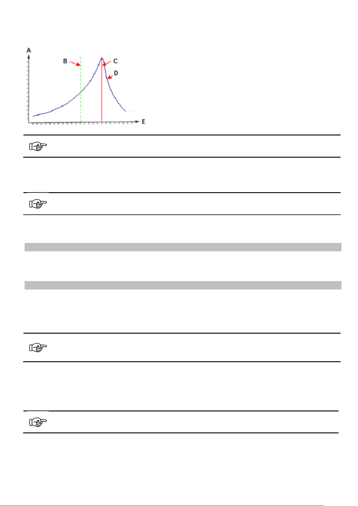
When you loosen the spring fastening screw you can observe a change in feeder speed.
The following graph shows the resonance curve of a vibratory feeder.
Notice
The resonance frequency of the vibratory feeder must not be equal to the mains frequency, it should be
lower than the driving frequency of the current.
If the feeder speed decreases after you loosen the spring fastening screw, proceed as described in section 5.1.
If, on the contrary, the feeder speed increases, proceed as described in section 5.2.
Notice
Tuning is facilitated by the use of an electronic frequency controller that is part of our standard product
range.
The vibratory feeder should be tuned so that the desired feeder speed is obtained with a controller setting of approx.
80%. This is to ensure sufficient magnetic saturation.
5.1. Feeder speed decreases?
Install additional springs. Start by adding one spring (including spacers) to one spring pack. If the feeder speed continues to decrease after you loosen a fastening screw anew, install additional springs one by one progressively in another spring pack until the desired speed is obtained with the controller set at 70 - 80%.
5.2. Feeder speed increases?
Remove springs. Start by removing one spring (including spacers) from one spring pack. If the feeder speed continues
to increase after you loosen a fastening screw anew, remove springs one by one progressively from another spring
pack until reaching a range where the feeder speed decreases when you loosen the spring fastening screws. In this
range the resonance frequency of the system is lower than the driving frequency of the current. Now proceed with the
actual tuning procedure as described in Section 5.1.
Notice
As the tuning procedure is done with the enclosure removed, be sure to add one more spring after finding
the optimum setting. This compensates the influence of the sheet metal enclosure on the frequency.
With type SRC-N 800 feeders, install 6 additional springs (one each in every 2nd spring pack).
Objective of the tuning procedure:
To set a stable feed rate matching the requisite amount of product.
When the desired feeder speed is obtained at a controller setting of 80 %, the feeder speed must always decrease
when the spring fastening screw is loosened.
Notice
Make sure that the number of springs per spring pack will not deviate by more than 2 – 3 springs. Otherwise the feeder speed at the circumference of the bowl is no longer constant.
A Feed rate
B Desired feeder speed
C Resonance frequency of the system
D Resonance curve
E Spring force (number of springs) increasing

Rhein-Nadel Automation GmbH 14
VT-MA-SRC 160-800-EN_2019 / 20.03.2019 SJ
Feeder speed is not constant?
If the feeder speed in the bowl is no longer constant you can balance the bowl by adding counter-weights.
• Attach a counterweight to the side that is running fast.
If the addition of counter-weights is not possible, you can also proceed as follows:
• Remove a spring from the spring pack located on the 'slow' side.
• Add a spring to the spring pack located on the 'fast' side.
Noise emission
The noise level at the place of use depends on the complete line in which the hopper will be incorporated and on the
material to be sorted. For this reason, sound pressure levels in accordance with the 'Machinery' directive can only be
determined at the place of installation.
If the noise level at the place of use exceeds the permissible, sound-insulating hoods can be installed which we can
offer on request (see our catalogue).
6. Maintenance
Vibratory feeders basically require no maintenance. They should only be cleaned when soiled or after coming into contact with liquids.
• Before starting such work pull the mains plug.
• Remove the enclosure.
• Clean the inside of the vibratory feeder, and in particular the air gap of the coil.
• After remounting the enclosure and plugging in the mains plug the vibratory feeder is again ready for operation.
7. Spare parts and customer service
For an overview of genuine spare parts available please refer to the separate spare parts list.
In order to make sure that your order is processed swiftly and correctly please specify the device type (see rating
plate), the quantity required, the spare part designation and the spare part number.
• Device type (see rating plate)
• Required quantity
• Spare part designation
• Spare part number
For a list of Service Center addresses refer to the back cover page of this manual.

Rhein-Nadel Automation GmbH 15
VT-MA-SRC 160-800-EN_2019 / 20.03.2019 SJ
8. What if...Advice on troubleshooting
Attention
The control unit or terminal box must only be opened by a professional electrician. Pull the mains plug before opening!
Fault
Potential cause
Remedy
Vibratory feeder does
not start on power up
Mains connector of control unit not plugged-in
Connecting cabled between vibratory feeder
and control unit not plugged-in
Only in conjunction with controller
ESK 2000
Sensor erroneously indicates part accumulation due to defect our misalignment
(green LED illuminated = vibratory feeder
'STOP')
Defective fuse in control unit
Power switch off
Plug in the mains connector
Plug 5-pin connector into control unit
Replace or re-adjust the sensor
Check if sensor is plugged-in
Replace fuse
Close power switch
Vibratory Feeders
vibrates only slightly
Controller set at 0 % on control unit
Wrong vibration frequency
Attention
If you operate a vibratory feeder designed
for 100 vibrations per second without having inserted the jumper in the 5-pin connector, there is a risk of damage to the
controller and magnet.
Set controller to 80 %
Check that coding in plug connector of the
controller is correct (see rating plate and
'Technical Data' (Section 1))
The vibratory feeder no
longer meets the requested feeding capacity after prolonged
operation.
Screws of one or more spring packs have
come loose.
Broken springs
Misadjusted coil-to-armature gap
Fixing screws of feeder bowl have come
loose.
Tighten screws (for tightening torques see
'Technical Data' in Section 1).
Replace broken springs
Readjust the air gap (for gap size see
'Technical Data' in Section 1).
Re-tighten the screws
Vibratory feeder makes
loud noises
Fixing screws of enclosure have come loose.
Bowl bottom is jammed
Foreign matter in air gap
(chips, or dust, parts handled)
Only for SRHL 400 and SRC-N 800:
Locking screw on armature plate has come
loose
Re-tighten the screws
Eliminate the jam
Stop linear feeder and remove foreign mat-
ter. Then check the coil-to-armature gap.
Re-tighten the screw
Vibratory feeder cannot
be tuned to a constant
speed for longer periods of time.
The spring constant of the vibrating system
has changed. The vibratory feeder operates
close to the resonance point.
Re-tune the vibratory feeder. Remove
springs. See Section 5: Tuning

RNA Group
Headquarters
Manufacturing and Sales
Rhein-Nadel Automation GmbH
Reichsweg 19-23
D-52068 Aachen
Phone: +49 (0) 241-5109-0
Fax: +49 (0) 241-5109-219
E-mail: vertrieb@RNA.dede
www.RNA.de
Further RNA group companies:
Manufacturing and Sales
Focus: Pharmaceutical Industry
PSA Zuführtechnik GmbH
Dr.-Jakob-Berlinger-Weg 1
D-74523 Schwäbisch Hall
Phone: +49 (0) 791 9460098-0
Fax: +49 (0) 791 9460098-29
E-mail: info@psa-zt.de
www.psa-zt.de
Manufacturing and Sales
RNA Automation Ltd.
Unit C
Castle Bromwich Business Park
Tameside Drive
Birmingham B35 7AG
United Kingdom
Phone: +44 (0) 121 749-2566
Fax: +44 (0) 121 749-6217
E-mail: RNA@RNA-uk.com
www.rnaautomation.com
Manufacturing and Sales
HSH Handling Systems AG
Wangenstr. 96
CH-3360 Herzogenbuchsee
Switzerland
Phone: +41 (0) 62 956 10-00
Fax: +41 (0) 62 956 10-10
E-mail: info@handling-systems.ch
www.handling-systems.ch
Manufacturing and Sales
Pol. Ind. Famades c/Energia 23
E-08940 Cornella de Llobregat (Barcelona)
Spain
Phone: +34 (0)93 377-7300
Fax +34 (0)93 377-6752
E-mail: info@vibrant-RNA.com
www.vibrant-RNA.com
www.vibrant.es
Further manufacturing sites
of the RNA Group
Manufacturing
Lüdenscheid branch
Rhein-Nadel Automation GmbH
Nottebohmstraße 57
D-58511 Lüdenscheid
Phone: +49 (0) 2351 41744
Fax: +49 (0) 2351 45582
E-mail: werk.luedenscheid@RNA.de
Manufacturing
Ergolding branch
Rhein-Nadel Automation GmbH
Ahornstraße 122
D-84030 Ergolding
Phone: +49 (0) 871 72812
Fax: +49 (0) 871 77131
E-mail: werk.ergolding@RNA.de
 Loading...