

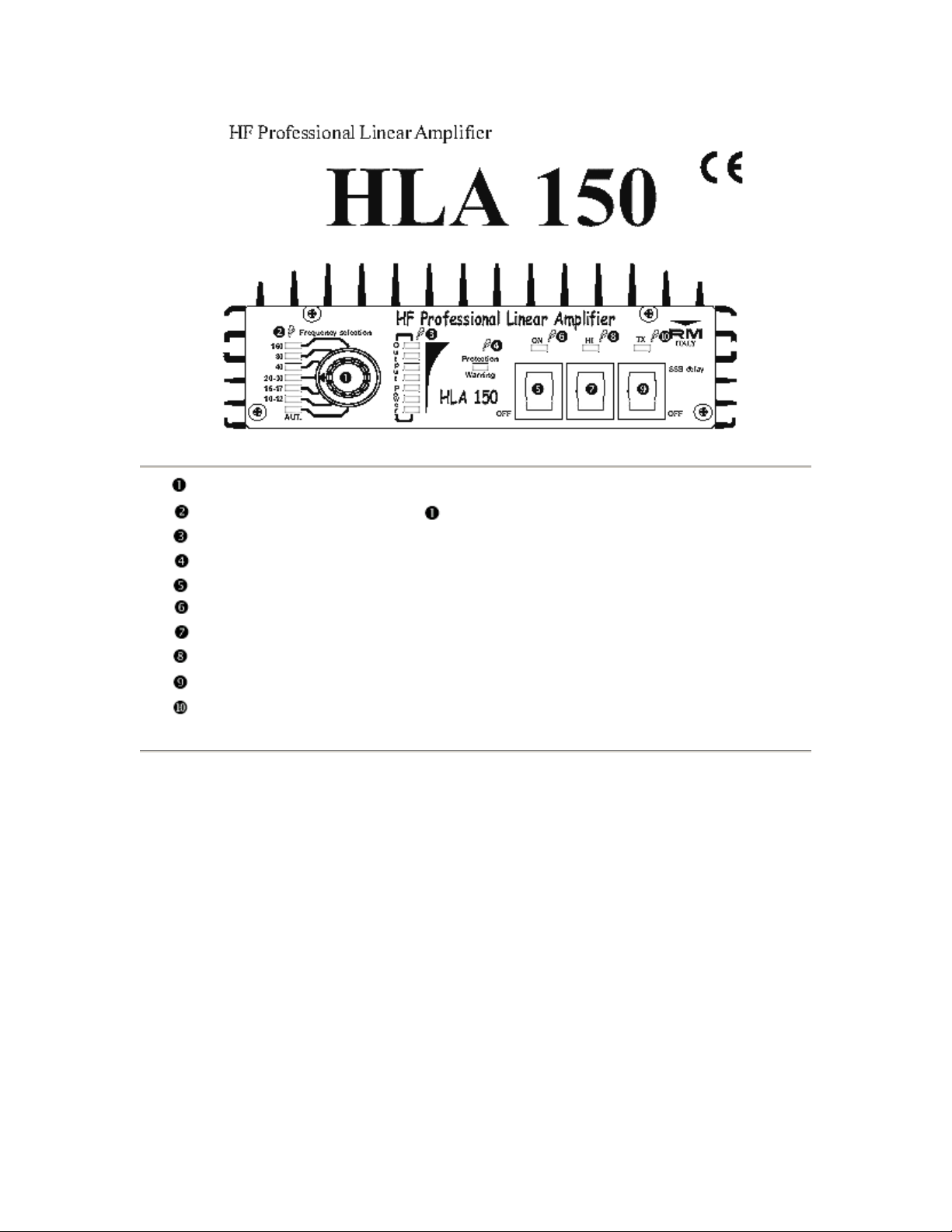
Band Selector Switch - select the working "band" or AUT. ( auto select mode)
Band Select indicator , when switch is in AUT. shows the currently used Band.
Power Output wattmeter.
Protection indicator.
Amplifier power switch.
Power on indicator Led.
Input attenuator switch.
Attenuator switch indicator Led.
SSB/CW delay switch.
Transmit indicator Led.
Specifications:
Frequency : 1.8 - 30 MHz - (10 - 160 meter )
Input power : 1 - 10 W AM - FM
: 1 - 15 W SSB - CW
Output power : 150 W Max AM-FM
: 250 W Max SSB-CW
Input SWR : 1.1/1.5
Antenna SWR Max : 2.5
Mode : All Modes
Fuse : 2 x 12 A
Power Supply requirements
Voltage : 13 VDC ± 1 V
Current : 24 A. Max Input

DESCRIPTION
The HLA 150 Linear Amplifier will meet the need for increased operating power with low power QRP
radios like the YAESU FT817 and ICOM IC703, etc. It is designed keeping in mind the need for
attenuation of the unwanted harmonic signals in the outputs.
The amplifier works on Amateur -Radio HF BANDS, 160 to 10 meters, in all modes. It features six LOWPASS FILTERS with 3 - 4 - 5 - 8 - 15 -22 - 31 MHz cut off frequencies, to drastically reduce harmonic
output power.
Control of the filter selection can be either AUTOMATIC or MANUAL.
AUTOMATIC - (Aut. on switch 1), is controlled by means of a microprocessor that reads the transmission
frequency and automatically selects the correct filter.
MANUAL - the band is selected by the position of switch 1. If the microprocessor detects the incorrect
filter has been selected, it will be indicated by an audio signal.
The amplifier incorporates a circuit to protect against HIGH SWR that stops it from working when the
SWR on the antenna is too high. This same circuit protects the Power Amplifier from damages caused by
incorrect setting of low pass filters.
The HLA 150V model features two fans on the aluminum heat sink, to more efficiently dissipate the heat
so the amplifier can be used in high temperatures environments as well as with intensive uses (contest etc.).
The fans operate at variable speeds to decrease the noise during receiving, when their use is not so
necessary.
INSTALLATION
Unpack the Amplifier and check for damages caused during transportation. There are two SO239
connector on the rear of the Amplifier. Connect the SO239 connector labeled RTX to your transceiver with
a RG58 cable, about 3 feet (90 cm.) long. Connect the antenna to the SO239 connector labeled ANT. Next,
be sure that the power switch (5) is in the OFF position. Connect the power cables to the vehicles battery
for mobile operation or to a power supply capable of providing 13.5 Volt at least 25 Amp under continuous
use. (Red = Positive, Black = Negative)
The power cables wire size must be no less than 12 AWG (4 mm²) and the length should not be more than
3 meters. The supplied voltage must not exceed 15 Volt. The Amplifier should be places in a position that
permit easily access to the controls. Be sure to leaving enough room around the amplifier to ensure good
ventilation.
ATTENTION!
Before using this Amplifier, be sure the antenna and power supply meet the required specifications.
Remember that the laws of each country regulate the use of linear amplifiers. The manufacturer cannot be
responsible if the amplifier is not operated according to these rules.
Failure to follow the provided instructions will result in the warranty being canceled. External and
aesthetics parts as well the final transistors are not covered by the warranty.

OPERATION
Switch the Amplifier ON with the power switch (5). The green LED indicator (6) will light when turned
ON. Other switches selected as required considering the following:
Switch (7) puts an Attenuator in or out of the input circuit. When the attenuator is not being used the
yellow LED (8) will be ON. The attenuator changes the power drive level by about 3 dB to improve the
amplifier gain when used with low levels of input power. When the input is over 8 Watt (12 PEP), the
attenuator must be used.
Switch (9), the position will depend on the mode of transmission. When the amplifier's VOX circuit is used
for the AM or FM modes, this switch must be in the OFF position. When operating in the SSB or CW
modes, the switch must be in the SSB delay position. SSB delay gives a 1 second delay to avoid the relay
returning to stand on low peaks in SSB modulation or between dits and dahs in CW mode. When a PTT
control line is connected to the rear of the Amplifier, switch (9) must be in OFF.
Switch (1) - The band switch must be placed in either the appropriate position for the band being used
(lighting the correct band LED), or on AUT. (lighting the yellow AUT. LED). If the wrong band is
selected during transmission, two conditions can occur:
- When the frequency is lower than that selected, the microprocessor warns of the error with
3 short audio signals, (the filter are low – pass type therefore if you use a filter with a too high
cut off frequency it is possible for one or more harmonics of the transmission frequency to be
radiated. (the amplifier will not be damaged).
- When the transmission frequency is higher the protection circuit is activated, (the red
Protection Warning LED (4) will light and the amplifier stops working.
When the frequency selected is not high enough (not dangerous condition), only the microprocessor starts
working, an intermittent audio sound will give a continuous indication of the danger of operating under
these conditions. The sound signals stop when the transceiver switches back to receive. Amplifier
Protection is indicated by Protection Warning LED (4). It must be manually reset by switching the
Amplifier OFF and ON.
See Appendix for information on the 6 LOW-PASS FILTER.
When the Amplifier is operating correctly, the TX LED (10) switches ON and the output power is indicated
by the LED bar graph meter (3).
Use the Amplifier only for long distance contacts and avoid transmitting for more than 5 minutes
continuous, without reasonable breaks to allow for cooling of transistors.
PROTECTION
When the Amplifier is operating, the Protection Warning indicator (4) is only activated if there is a danger
to the Amplifier. Some possible causes were are:
- Selecting a frequency lower then the one used.
- Operating into an antenna with a high level of standing waves (SWR).
To return to regular the amplifier to normal use, after the protection circuit has activated, turn off the
amplifier (switch 5), correct the problem, then turn the power back on (switch 5).
If the temperature becomes too high, a temperature sensor stops the amplifier from operating and an audio
indication is sounded. The amplifier will operate normally again when the temperature returns to normal.
** English Manual update by VE5KC – 1st draft March 17, 2004
 Loading...