


Ultrasonic Flowmeter USM GT400
OPERATING INSTRUCTION
Reliable Measurement of Gas
Read the instructions before starting work!

Manufacturer Our customer service is available for technical queries:
Address RMG Messtechnik GmbH
Otto-Hahn-Str. 5
D-35510 Butzbach
Telephone Switchboard +49 6033 897-0
Telephone Service +49 6033 897-0
Telephone Spare Parts +49 6033 897-173
Fax +49 6033 897-130
E-Mail service@rmg.com
Original Document
Note
The Ultrasonic Flowmeter USM GT400
OPERATING INSTRUCTION 9/4/2018 is the origi
This document may serve as a reference for transla
nal document.
tions into
other languages. Please use in case of any uncertainties the
German version as main reference.
Unfortunately, paper is not updated auto
matically, whereas
technical development continuously advances. Therefore, we
reserve the right to make technical changes in r
representations and specificatio
ns of these operating
egard to the
instructions. The latest version of this manual (and other devices)
downloaded at your convenience from our Internet home-
can be
page:
www.rmg.com
Date created 1/31/2014
1st revision date
2nd revision date
5/12/2014
9/18/2015
9/29/2017
2/16/2018
09/04/2018
September, 4
th
2018
Document version and language
3rd revision date
4th revision date
5th revision date
Document version Ultrasonic Flowmeter USM GT400
Language EN
I Ultrasonic Flowmeter USM GT400 September, 4
th
2018

Contents
1 About this manual
1.1 Objective of the manual ........................... 1
1.2 Specialized knowledge required .............. 2
1.3 Abbreviations ........................................... 2
1.4 Symbols ................................................... 3
1.5 Validity of the manual .............................. 3
2 Brief instructions
2.1 Mechanical connection ............................ 5
2.2 Electrical connection................................ 6
2.3 Start Up.................................................... 7
2.4 Earthing ................................................... 7
2.5 Parameter setting .................................... 8
3 Device overview
3.1 Main components .................................... 9
3.2 Ultrasonic electronics............................. 11
3.3 Arrangement of the
ultrasonic transducers............................ 15
4 Functional principle - Ultrasonic flow
measurement
8 Installation
8.1 Assembly work preparations ................. 78
8.2 Installation of the device........................ 80
8.3 Connecting the device electrically ......... 84
8.4 Installing the pressure connec
8.5 Outdoor installation.............................. 114
tion....... 112
9Start Up
9.1 Comparing meter parameters.............. 115
9.2 Checking functions of the USM ........... 115
9.3 Reading out speed of sound................ 116
10 Operation
10.1 Measuring values and parameters ...... 118
10.2 Calling up and changing the parameters
via the ultrasonic electronic
10.3 Parameterize the USM i
10.4 Modbus communication in detail ......... 141
10.5 List of the measure
parameters .......................................... 143
ment values and
s ............... 121
nterface ......... 131
11 Maintenance
4.1 General description................................ 17
4.2 Correction of the base line..................... 21
4.3 Diagnostic function Speed of Sound...... 24
4.4 Import of gas compositi
4.5 Batch mode............................................ 36
on data.............. 27
5 Safety
5.1 Intended use .......................................... 37
5.2 Layout of instructions............................. 38
5.3 Qualification of the personnel ................ 39
5.4 Safety instructions ................................. 39
5.5 Responsibilities of the operator ...
.......... 46
6 Transport and storage
6.1 Transport ............................................... 47
6.2 Packing the device for transportation
6.3 Storage .................................................. 62
.... 55
7 Construction and Planning
7.1 Connection flanges ................................ 65
7.2 Seals...................................................... 66
7.3 Screws ................................................... 70
7.4 Installation possibilities .......................... 71
7.5 Flow computer ....................................... 75
11.1 Maintenance schedule......................... 146
11.2 Checking the device for leaks
11.3 Checking the device for any signs of
damage................................................ 147
11.4 Changing the battery .
11.5 Changing the transducer
11.6 Changing the ultrasonic elect
11.7 Cleaning the device ............................. 148
11.8 Check the official seal.......................... 149
11.9 Decommissioning and disposal ........... 149
.......................... 147
.............. 146
..................... 147
ronics..... 148
12 Alarm and warning messages
12.1 Alarm messages.................................. 151
12.2 Warning messages...........
12.3 Notes ................................................... 157
12.4 Troubleshooting................................... 157
................... 154
13 Technical specifications
13.1 Performance data................................ 160
13.2 Approved gas types ............................ 160
13.3 Approved measuring range according
to MID.................................................. 161
13.4 Type plate............................................ 162
13.5 Weights and dimensions ..................... 163
September, 4th 2018 Ultrasonic Flowmeter USM GT400 II

Contents
13.6 Inner diameter of connecting
spool pieces......................................... 168
13.7 Official seal diagram ............................ 169
13.8 Transducer types
14 USM GT400 Approval
14.1 Metrological approvals......................... 177
14.2 Pressure devices approval .
14.3 Electromagnetic compatibility ..............177
14.4 Explosion protection approval.............. 177
14.5 Standards, directives and guidelines... 178
15 Index
16 USM GT400 Glossary
17 USM GT400 Attachment
................................. 175
................. 177
18 Lists of parameters and measured
values
III Ultrasonic Flowmeter USM GT400 September, 4th 2018

1 About this manual
1
1.1
About this manual
In this chapter you will be given information on this manual.
Contents 1.
1.1 Objective of the manual ...................................... 1
1.2 Specialized knowledge required
1.3 Abbreviations
1.4 Symbols
1.5 Validity of the manual
Objective of the manual
....................................................... 2
................................................................ 3
........................ 2
.......................................... 3
The manual provides you with the information that is designed for
trouble-free and safe operation.
The ultrasonic gas meter is state of the
manufactured according to the recognized safety standards and
guidelines.
However, risks may arise during us
by observing this manual..
For this reason, you may only use the device as intended and in
cally sound condition.
techni
If the ultrasonic gas meter is not used for it
warranty claims will be void.
art and conceived and
e that can be easily avoided
s intended purpose,
September, 4th 2018 Ultrasonic Flowmeter USM GT400 1

1 About this manual
1.2
Specialized knowledge required
Persons working with or on the device must have the following
knowledge:
• training /
environments.
• the ability
the device. Possible dangers are, e.g., components under
pressure or the result of incorrect installation.
• r
ecognize dangers that could be cau
medium.
• training /
instruments.
• education / instruc
directives to be observed for work that is to be carried out on
the device.
Further information can be found under:
Chapter 5.3, „Qualification of the personnel“ on page 39
education for wo
to correctly ass
education b
tion in all c
rking in potentially explosive
ess dangers and risks when using
sed by the used flow
y RMG for working with gas measuring
ountry-specific standards and
1.3
Abbreviations
The following abbreviations are used:
AGC Automatic Gain Control
ca. circa, approximately
as app. as applicable
max. maximum
MC Measurement Canada
MID Measurement Instruments Directive
min. minimum
SNR Signal to Noise Ratio
SoS Speed of Sound
TD Transducer (ultrasonic transmitter and
receiver)
TNG Transducer of a certain production type.
USE Ultrasonic electronics
USM Ultrasonic gas meter
e.g. For example
2 Ultrasonic Flowmeter USM GT400 September, 4th 2018

1 About this manual
1.4
Symbols
The following symbols are used:
1, 2, ... Marks steps within a work operation.
Marks steps in an illustration that are
described in the text.
(A) Reference to a component (element) marked
with a letter in an illustration.
Marks elements in an illustration. The arrow
points to the element being described.
Print Screen Marks switches, regulators, slides, buttons
Marks a cross-reference that refers to
another part in this manual or in another document.
and other terms from the software are
marked by bold text.
1.5
Validity of the manual
This manual describes the Ultrasonic Flowmeter USM GT400.
The Ultrasonic Flowmeter USM GT400 d
complete on site system. Observe also the instructions of other
components of the site system.
If you find contradicting instructions
evice is only a part of a
, please contact RMG.
September, 4th 2018 Ultrasonic Flowmeter USM GT400 3

1 About this manual
4 Ultrasonic Flowmeter USM GT400 September, 4th 2018

2 Brief instructions
2
2.1
Brief instructions
This chapter does not replace the rest of the operating instructions. It shows only a brief section of t
to make the device ready for operation.
The chapter is only directed at experienced users.
• Observe the chapter safety.
Section 5, "Safety" on
Detailed information for this content can be found under:
Section 7, "Construction and Planning" on page 65
Section 8, "Installation" on page 77
Section 9, "Start Up" on page 115
Section 12.4, "Troubleshooting" on page 157
Mechanical connection
page 37
he steps necessary in order
2.1.1
2.1.2
Operating mode Inlet piping Outlet piping Temperature sensor
Unidirectional operation 10 D (no flow conditioner) 3 D 1.5 D to 5 D
Unidirectional operation 3 / 5 D (with RMG or stan-
Bidirectional operation 10 D (no flow conditioner) 10 D (no flow conditioner) 3 D to 5
Bidirectional operation 3 / 5 D (with RMG or stan-
1 Depending on the nominal width.
Connection flanges
1 Make sure that the device and the connection flange have
the same pressure rating / flange standards.
2 Make sure that the device is sealed with the appropriate
seals.
Inlet / outlet piping
dardized flow conditioner)
dardized flow conditioner)
1
1
position
3 D 1.5 D to 5 D
D
3 / 5 D (with RMG or standardized flow conditioner)
1
2 D to 5 D
1
–See also "Inner diameter of connecting spool pieces" on
page 168
September, 4th 2018 Ultrasonic Flowmeter USM GT400 5

2 Brief instructions
2.1.3
2.2
Joining pressure connections
Establish connection with the clamping screw connec-
tion
3 Unscrew the union nut of the clamping screw connection.
4 Remove the blind plug.
5 Push the union nut and clampin
6 Push the pipe into the clamping screw con
stop.
7 Tighten the union nut in order to fix and seal t
Establish connection with the female thread
8 Unscrew
9 Seal the connection in the thread.
the blind plug.
Electrical connection
g ring
s onto the pipe.
nection until the
he pipe.
Fig. 2-1: Connection assignment on the terminal strip
10 Connect the computer to the terminals RS 485-0.
11 Allocate the terminal strips according to the applications.
Option: connect ERZ 2000 (-NG) to RS 485-1.
6 Ultrasonic Flowmeter USM GT400 September, 4th 2018

2 Brief instructions
2.3
2.4
Start Up
Earthing
12 Supply the device with power supply (24 V DC) via the
system.
If the power LED illuminates green permanently,
ready for operation.
If the alarm and warning LED do no
ates trouble-free.
Section 3.1, "Light emitting diodes" on page 14
The USM-GT-400 is supplied without connection box to the North
American
through a flame arrester. The marking of the cable (numbers) is
(always) identical to the terminal assignment.
region, the connection is made to cables that are led
t flash, the device oper-
the device is
A Earthing screw M6 B Earthing screw M6
C Earthing cable
Fig. 2-2: Connect to earth - Ultrasonic gas meters DN150 (6")
and DN100 (4")
September, 4th 2018 Ultrasonic Flowmeter USM GT400 7

2 Brief instructions
A Earthing screw M6 B Earthing screw M6
C Earthing cable
2.5
Fig. 2-3: Connect to earth - Ultrasonic gas meter DN200 (8")
13 Connect the earthing cable according to the ultrasonic gas
meter version DN100 (4") to DN150 (6") or from DN200 (8").
Parameter setting
The device shall be supplied pre-assembled according to customer agreement. Changes to the pre-assembly are more
exten
sive and are therefore not described in this brief instruction.
If this should be necessary, you will then find the description:
Section 10.1.3, "Calibration and Service Switch" on page 119
8 Ultrasonic Flowmeter USM GT400 September, 4th 2018

3 Device overview
3
3.1
Device overview
In this chapter you will receive information on the main components of the ultrasonic gas meter and the arrangement of the
ultrason
Contents 3.
3.1 Main components ................................................ 9
3.2 Ultrasonic electronics
3.3 Arrangement of the ultrasonic transducers
Main components
ic transducers in the housing of the ultrasonic gas meter.
....................................... 11
.... 15
A Covers of the transducer and
transducer lines
C Ultrasonic electronics D Lifting eyes
E Joining flanges F Transducer
G Retaining bolts
Fig. 3-1: Main components of the ultrasonic gas meter
The ultrasonic gas meter consists of the following main
components:
September, 4th 2018 Ultrasonic Flowmeter USM GT400 9
B Covers of the transducer lines

3 Device overview
Covers of the transducers (A and B) The covers protect the connections and the lines of the transduc-
er (TD) against contamination and mech
anical damage.
Ultrasonic electronics (C) The ultrasonic electronics is in a pressur
housing mounted on the ultrasonic gas meter. The ultrasonic
electronics evaluates the data recorded by the transducers. In
addition to the display, the parameters can be shown and evaluated on a computer using the RMGView
Lifting eyes (D) The lifting eyes can be used to safely transport the device using
a
suitable lifting gear.
Connection flange (E) The device is bolted onto the g
flanges.
Transducer (F) The transducers are installed in the housing of the ultrasonic ga
eter and are not visible once installed.
m
Retaining bolts (G) The retaining bolts are mounted when delivering the device. The
retaining bolts
away. The bolts must be mounted to ensure for a safe installation
or de-installation.
secure the product from tipping over or rolling
s line using the connection
a
e tight, encapsulated
USM
software.
s
10 Ultrasonic Flowmeter USM GT400 September, 4th 2018

3 Device overview
3.2
Ultrasonic electronics
A Service and calibration switch B Control panel
C Display D Magnet for operation
E Cover with viewing window F Pressure tight housing
Fig. 3-2: Ultrasonic electronics and displ ay
Device data (readings and parameters) can be set and evaluated
via the display and the operating elements.
Moreover, the device data (readings
shown, evaluated and set using the RMGView
Service and calibration switch (A) The service switch (right switch) is o
vice switch is, e.g., used to ins
The calibration switch (left switch) protects the pa
against unauthorized changes. The device can be configured by
opening the calibration switch.
Control panel (B) The control field comprises buttons that are triggered by pressing
a butto
and status messages are called up using the button.
Display (C) The display shows the readings, warning , alarm and status mes-
sages as well as the parameters.
Magnet for operation (D) The magnet is used to operate the control panel of the ultrasonic
el
above the symbol on the viewing window, this function is
activated.
n or magnetically. Parameters, readings, warning, alarm
ics when the housing is closed. If the magnet is placed
ectron
tall new firmware.
and parameters) can also be
nly for RMG service. The ser-
USM
software.
rameters
September, 4th 2018 Ultrasonic Flowmeter USM GT400 11

3 Device overview
Cover with viewing window and
pressure tight housing (E and F)
Electrical connection
(T
erminal strip)
First line Shows the name of the parameter (coordinates) called-up, e.g.,
The cover and the pressure tight housing encapsulate the ultrasonic electronics against the potentially e
During operation, information can be read through the viewing
window from the display and status indicat
re information on the electrical connection can be found here:
Mo
Chapter 8.3, „Connecting the device electrically“ on page 84
xplosive atmosphere.
ors of the LEDs.
Display screen
Fig. 3-3: Example for a possible disp l ay
p-maximum value (maximum pressure value).
Second line Shows the value of the parameter (
52.00 bar a.
Third line Shows the coordinate designation, e.g., A-06, thus column A, line
06.
The calibration switch is open. The value of the parameter can be
changed.
The calibration switch is closed. The value of the parameter cannot be changed.
Forth line Shows the warning, alarm and status messag
failure
coordin
ates) called-up, e.g.,
es, e.g., -01 power
12 Ultrasonic Flowmeter USM GT400 September, 4th 2018

3 Device overview
Buttons
When the cover is closed, the buttons can be operated through
the glass using the magnets supplied. The cover must not be
opened.
Change to the columns. Jump, e.g., from A to B and back again.
When holding for a longer time, you can change the columns by
quickly scrolling back.
Change or scroll forwards in the lines step by step, e.g., from A01 to A-02.
When holding for a longer time, you can change the lines quickly
scrolling forward.
Change or scroll back in the lines step by step, e.g., from A-01 to
A-02.
When holding for a longer time, you can ch
quick return.
Enter values.
ange the lines with
Reset button
The reset button (A) is for RMG service only. If the reset button is
pressed, the ultrasonic electronics is restarted.
Switches
Calibration switch (A): Activate to change parameters.
Service switch (B): For RMG service only. For in
firmware.
stalling a new
September, 4th 2018 Ultrasonic Flowmeter USM GT400 13

3 Device overview
Light emitting diodes
A Flow B Power (supply voltage)
C Alarm D Warning
E Reset F Service (service switch state)
G Calibration (calibration switch
state)
Fig. 3-4: LEDs of the electronic ultrasonic electronics
LED Illuminates con-
H Button states
flashing
tinuously
Power Voltage supply is
switched on.
Flow Gas flow present. —
Alarm Alarm message is
stored.
Warning Warning message is
stored.
Reset Reset is running.
Calibration Calibration switch is
open.
—
Alarm is active.
Warning is active.
—
—
Service Service switch is
open.
Control panel Panel is being
pressed.
—
—
14 Ultrasonic Flowmeter USM GT400 September, 4th 2018

3 Device overview
3.3
Arrangement of the ultrasonic transducers
Fig. 3-5: Transducer paths and levels of the ultrasonic gas meter
The figure shows the arrangement of the transducers that are located in the ultrasonic gas meter. The arrangement of the
transd
ucers in the three levels is shown in three section
representations.
Four transducers are installed per level. The transducers form
two paths per level for
September, 4th 2018 Ultrasonic Flowmeter USM GT400 15
the measurement.

3 Device overview
16 Ultrasonic Flowmeter USM GT400 September, 4th 2018

4 Functional principle - Ultrasonic flow measurement
v
4
Functional principle - Ultrasonic
flow measurement
Content 4.
4.1 General description ........................................... 17
4.2 Correction of the base line
4.2.1 Base line correction via polynomial ........................ 22
4.2.2 Correction via a piecewise lin
4.3 Diagnostic function Speed of Sound ............... 24
4.3.1 Standard method of SoS calculation ...................... 24
4.3.2 SoS calculation via gas compone
4.3.3 Extended SoS calculation
4.4 Import of gas composition data ....................... 27
4.4.1 Option 4: Data input on fixed defaults .................... 27
4.4.2 Option 4: Data input on fixed defa
4.4.3 Data input via RMGBus
4.4.4 Data via Modbus (USM-GT-400 is SL
4.4.5 Import of data via Modbus (U
31
............................... 21
earization ................. 24
nts ...................... 24
...................................... 25
ults for air .......... 28
.......................................... 30
AVE) ........... 30
SM-GT-400 is Master) ..
4.1
4.5 Batch mode ........................................................ 36
General description
In this chapter, you are provided with information as to how the
ultrasonic gas meter records the data. The necessary formulas
are listed for this purpose.
Figure 4.1 shows the general working principle. Transducer TD1
and TD2 ar
ment and form a measurement path wit
ultrasonic pulse travels along the measuring path from sensor
TD1 to transducer TD2 more quickly than the other way around.
This is caused physically by vector addition of the flow velocity to
the speed of sound, the arrow above the
of flow.
e positioned opposite to each other for the measure-
h distance L. An
shows the direction
September, 4th 2018 Ultrasonic Flowmeter USM GT400 17

4 Functional principle - Ultrasonic flow measurement
: t=
TD12
: t=
TD21
t
TD12
L
c0v cos+
---------------------------------
=
t
TD21
L
c0v cos–
-------------------------------- -
=
v
v
L
2 cos
---------------------
1
t
TD12
-------------
1
t
TD21
-------------
–
=
v
L
2
2 d
-----------
t
TD21tTD12
–
t
TD12tTD21
--------------------------------- -
L
2
2 d
-----------
t
t
TD12tTD21
------------------------------- -
==
Formulas
Fig. 4-1: Two sensors form one path for the measurement
The transit time from TD1 to TD2 (
TD1 (
formula:
Fig. 4-2: Formula, transit time
These transit times of the ultrasonic pulses are determined by the
electronic ultrasonic system. These are used to determine the average velocity
) are calculated according to the following
along the measuring path:
) and from TD2 to
Fig. 4-3: Formula, average path velocity
Legend
18 Ultrasonic Flowmeter USM GT400 September, 4th 2018
v: Average flow velocity
c0: Speed of sound
: Path angle to the pipe
L: Path length

4 Functional principle - Ultrasonic flow measurement
v
i
v
i
=
v
ki
kv
i
=
v
w
wivki
i 1=
6
=
d: Diameter D
(For a center path. Outer paths have a corresponding
value.)
For this calculation, it is important that only the transit times and
the device parameters such as the transducer distance and the
angle of the measuring path to the flow direction are required. All
parameters that include a gas dependency are omitted.
Legend
In order to consider the ave
rage flow profile, in particular an
asymmetrical or swirl-affected flow, a total of 6 paths is measured
in 3 levels with the USM-GT-400 ultrasonic gas meter. The 3 levels can be derived ma
tically via an integration procedure,
thema
the so-called Gauss integration.
"Arrangement of the ultrasonic transducers" on page 15
The respective average path velocities (designated with
for the respective measuring path i) along these measuring paths
results analogically to the fo
Under certain conditions such as, e.g., sm
rmula above.
aller deviations from
the tolerances during the production, it may be necessary to correct the path velocities with a common factor:
Fig. 4-4: Formula, corrected path v elocity
v
k = Correction factor for the path velocities
= Corrected path velocity (m/s)
ki
(This factor is named vw factor d1for the forward
direction and vw factor d2 for back-flow; see
chapter parameter setting 10.5.4)
Thus, one obtains for the average flow velocity:
Fig. 4-5: Formula, flow velocity
Legend
v
w
= Average flow velocity (m/s)
w
= Weighting factor with regard to the flow profile
i
The summation and the weighting specified result from the mathematic Gaussian integration procedure.
September, 4th 2018 Ultrasonic Flowmeter USM GT400 19

4 Functional principle - Ultrasonic flow measurement
i
i
Tu
20;6..1
1
1
1
2
,
Nivv
N
N
j
iiji
i
i
i
v
Tu
i
v
ijv,
N
PF
Quality of installation
The USM-GT-400 provides parameters that allow a rating of the
installation. If the values are within given ranges, then good measurement conditions can be assumed. If the
the accuracy of the reading may be affected by disturbed flow
conditions. Please contact in this case the RMG service.
"Manufacturer" on page I
Turbulence
Due to the actual flow, in particular the turbulence, there will be
characteristic variations (variance
locities (i = 1..6; number of ultra
allow an assessment of the installation. The ultrasonic path averaged turbulence (
) is calculated as follows:
values are outside
) of the individual path ve-
sonic measuring paths), which
Legend
Fig. 4-6: Variance
Fig. 4-7: Turbulence
=
Time averaged flow velocity along the ultrasonic
path
=
Flow velocity along the ultrasonic path
=
20; number of values for turbulence calculation
(named Turb./Perf. count; see chapter parameter)
Typical values at very good flow conditions for
at 2-3%, for the outer paths, the turbulence increases to 4%. If
these values are above 10%, then disturbed conditions can be
assumed affecting the measurement accuracy. At lowest velocities the turbulence calculation is
swit
ched off.
middle paths are
Profile and symmetry factor
For a fully developed flow the middle path (3 + 4) have the highest
velocity, the two outer paths (1 + 2; 5 + 6) are more or less equal.
The profile factor (
20 Ultrasonic Flowmeter USM GT400 September, 4th 2018
) is typically between 1.05 to 1.20; at val-

4 Functional principle - Ultrasonic flow measurement
6521
43
2
vvvv
vv
PF
65
21
vv
vv
SY
MP
600
)(0)(1
,
100..16..1
,
okvokv
MP
ij
ji
ij
ues below 1.00 or above 1.50, the flow conditions should be
checked.
Fig. 4-8: Profile factor
The symmetry factor (SY) usually is between 0.9-1.10; at values
below 0.75 or above 1.25 the flow conditions should be checked.
Fig. 4-9: Symmetry factor
Meter performance
This value (
paths could be measured and involved in the flow c
is calculated on base of the last 20 measurements (same as
turbulence).
Fig. 4-10: Meter performance
The highest value is 100%; under normal conditions it is above
95%. Since 2 measurement paths can fail before the
USM-GT-400 loses its calibrated accuracy,
down to 66%; if the path failure is caused by a defect transducer
an immediate repair of the failed transducers should to be
initiated.
All of these values are given at the display of th
they are identical to the values in the RMGView
) indicates whether the velocity of all ultrasonic
alculation. It
the value may fall
e USM-GT-400;
USM
.
4.2
September, 4th 2018 Ultrasonic Flowmeter USM GT400 21
Correction of the base line
Correction of the baseline for the velocity
There are several influences (eg. Reynolds number) resulting in
a not exactly proportional relation between the measured and according to the formula 4.5 calculated mean v
elocity to the exact

4 Functional principle - Ultrasonic flow measurement
v
wk
vwK
v
1
F
100
---------
+
=
Q
m
vw
D
i
2
4
--------
3600
s
h
-- -
=
Q
mk
kkv
wk
D
i
2
4
--------
3600
s
h
-- -
=
F
1
const G
m2
–
v
w
2
-------------------------------
const G
m1
–
v
w
2
-------------------------------
const G0– const G1–v
w
const G2–v
w
2
++++=
mean velocity. Here the following correction helps to compensate
these variations:
Bild 4-11: Formula, corrected average flow velocity
Legend
Legend
v
K
F = Error from the characteristic curve correction
These values can be used to calculate the process volume flow
rate respectively the corrected process volume flow:
Fig. 4-12: Formula, process volume flow
Fig. 4-13: Formula, corrected process volume flow
Q
= Corrected average flow velocity (m/s)
wk
= Meter factor
V
= Corrected process volume flow
mk
v
D
k
A 4
the device:
4.2.1
Fig. 4-14: Formula - Basic correction of the device
22 Ultrasonic Flowmeter USM GT400 September, 4th 2018
Base line correction via polynomial
Legend
F
= Corrected weighted flow velocity
wk
= Inside pipe diameter
i
= Characteristic curve correction
k
th
degree polynomial permits the so-called basic correction of
1
= Deviation of the error curve (%)

4 Functional principle - Ultrasonic flow measurement
v
wk
vwK
v
1
F
100
---------
+
= v
wkvwKv
1
F
1
100
---------
+
=
F
2
const m2–
Q
m
2
----------------------------
const m1–
Q
m
----------------------------
const 0– const 1–Q
m
const 2–Q
m
2
++++=
K
k
1 F
2
+
100
----------------
=
v
w
const-Gx
The constants const-Gx (x = m2, m1, 0, 1, 2) are calculated from
the measured value pairs of the deviation with the respective flow
velocity.
The calculated correction F
flow velocity for F in the formula above.
Fig. 4-15: Formula, corrected meter factor
The process volume flow and the corrected process volume flow
result, as listed above, from the multiplication of the corresponding velocities with the pipe cross-section. The correction formulas
above are ther
flows.
= Average flow velocity (m/s)
= Constants of the basic correction
(x = m2, m1, 0, 1, 2)
is used for the corrected average
1
efore accordingly easy to transfer to the volume
Polynomial The characteristic curve correctio
Fig. 4-16: Formula, error equation
lso carried out via a 4th
n is a
degree polynomial that represents the error curve of the device.
F
2
Q
m
const-n
The constants Konst-n (n = m2 bis n = 2) are calculated from the
measured value pairs error F
curve correction K
process volume flow.
= Deviation from the error curve (%)
= Flow (m3/h)
= Constants
and flow Qbi. The characteristic
2i
is used for further calculation of the corrected
k
Fig. 4-17: Formula, characteristic curve correction
September, 4th 2018 Ultrasonic Flowmeter USM GT400 23

4 Functional principle - Ultrasonic flow measurement
12TD
t
12TD
t
L
SoS
0
c
2112
2112
0
2
TDTD
TDTD
tt
ttL
cSoS
4.2.2
4.3
Correction via a piecewise linearization
The correction of the base line with a polynomial described in
section 4.2.1 takes into account the typical, characteristic curve
of the USM-GT-400 in an ideal way. This correction is recommended for custody transf
MID is valid. Nevertheless, a comparable accuracy can be
achieved with a piecewise linearization, if a sufficient number of
interpolation points are used. Between the interpolation points, a
simple linear interpolation is used. The correction of the base line
with the piecewise linearization may also be used in all countries
where the MID is valid if the error curve of the raw data mets the
requirements of the ISO 17089.
In order to achiev
points should be placed in the relevant flow rate range. To take
into account the higher gradient of the curve at lower flow rates
the intervals should not be equidistant; recommended are more
points in this lower flow rate range.
a sufficient accuracy most of the measuring
e
etering in all countries where the
er m
Diagnostic function Speed of Sound
4.3.1
4.3.2
The USM-GT-400 can calculate the SoS in 3 different ways.
Standard method of SoS calculation
The first calculation is realized with help of the transit time
and
suring path with the length
speed of sound
Fig. 4-18: Calculation of SoS
This first option is pretty fast and is almost permanently "online"
available.
of the ultrasonic pulses (see above) along the mea-
. It is straight forward to result in the
or
to:
SoS calculation via gas components
The second version of SoS calculation uses pressure, temperature and composition of the gas to determine the SoS according
to the
specifications of the AGA 10 standard (AGA Report No. 10,
24 Ultrasonic Flowmeter USM GT400 September, 4th 2018

4 Functional principle - Ultrasonic flow measurement
Speed of Sound in Natural Gas and Other Related Hydrocarbon
Gases; January, 2003; AGA - American Gas Association). The
calculation is based on statistical considerations of thermodynamics; since it is very complex
Knowing the gas composition precisely values such as density,
sound velocity and other gas properties can be calculated with
very high accuracy.
Depending on the type of gas analyzer it may take 5-10 minutes
to determine the volume fractions
nents accurately. Accordingly, the precise allocation of flow to
gas composition can be done in this time frame only.
, it will not be pres
of the individual gas compo-
ented here.
the
Diagnostic function SoS
The USM-GT-400 determines with highest accuracy the flow rate
of the gas flowing through it. For the payoff the gas quality, respectively the calorific value of the gas resulting from the gas
composition
lows a second billing of the volume flow rate with the "right" ga
composition, ie the "right" calorific value.
is of course of big interest, too. The USM-GT-400 al-
s
4.3.3
This temporal resolution can be achieved receiving permanently
gas composition data from a gas analyzer. A comparison of
the
the two differently calculated SoS‘s in the USM-GT-400 allows
the immediate detection of any deviation; in particular, another
gas composition results in a different SoS. A confirmation of another gas composition then provide
the data of the gas analysis instrument.
The temporal correlation of the actual gas composition (using the
calculated via the gas composition) to the SoS using method
SoS
1 results in the higher temporal resolution for the gas composition, respectively the
Extended SoS calculation
The third possibility SoS calculation is presented under the name
"Extended SoS measurement". This new method is introduced
as an additional determination.
orific value.
cal
s the n
ext comparison with
September, 4th 2018 Ultrasonic Flowmeter USM GT400 25

4 Functional principle - Ultrasonic flow measurement
12TD
t
122112TD
t
122112TD
t
12TD
t
SoS
1212211212
12122112
2112
2112
0
22
2
TDTDTD
TDTD
TDTD
TDTD
ttt
tt
L
tt
ttL
cSoS
Fig. 4-19: Extended SoS calculation
Transducer TD2 receives at first the ultrasonic pulse (light blue)
coming from TD1 at the time (
ed and moves back to TD1 (dark blue). There this puls
reflected, too and reaches TD2 (red) again after the time
(
a new possibility to calculate
Fig. 4-20: Calculation of extended SoS
Due to a 10-times smaller variance of the SoS calculation this
method offers significantly more accurate result compared to the
standard method (version 1). There are 2 reasons for this result;
first, the transmitter / receiver error is eliminated (especially T
the transit time of the pulse in electronic and transducer is different in the individual transducers) and secondly, any
turbulence in medium has lowest influence to the transit time (the
time interval between 12TDt and 21TDt is as short as possible).
Having typical measuring conditions, this method can easily be
applied, but there are conditions at which this method may fail.
). The differences of
). This pulse is partially reflect-
e is
and
:
results in
W
flow
;
The SoS calculation according to method 1 and 3 run simultaneously and controlled using the same criteria. If correct, the result
o
the extended measurement is preferred due to its higher accu-
f
26 Ultrasonic Flowmeter USM GT400 September, 4th 2018
racy. Otherwise, the standard method 1 is used; after any change

4 Functional principle - Ultrasonic flow measurement
the measurement conditions, both methods are revalued again.
If correct the extended SoS calculation will be chosen again.
TW setting
Measurement tolerances and/or errors of the standard method
are permanently controlled using the comparison with the expanded method. Having both values
determined. When the calibration switch is open, the T
the standard measurement can be corrected to the value of the
extended measurement. This is an important adjustment help in
case of a transducer replaced, but also serves as an accurate
path lengths determination between the transducers during the
dry calibration.
a correction for TW can be
-value of
W
4.4
Import of gas composition data
To use the diagnostic function SoS, respectively to calculate it
from the gas composition the USM-GT-400 requires the volume
fractions of the individual gas components in the gas (up to 21
components), the pressure and the temperature. From these
data SoS is calculated using the guidelines of the AGA 10 standard. For the data transfer of the
are available:
gas com
ponents four options
Fig. 4-21: Import of gas composition data
4.4.1
September, 4th 2018 Ultrasonic Flowmeter USM GT400 27
Option 4: Data input on fixed defaults
If there are no live data available for the gas analysis, then the
gas data can be stored as fixed values in the USM-GT-400. For

4 Functional principle - Ultrasonic flow measurement
the AGA-10 calculation these default values are used as fixed
gas shares (AX-20 - AX-44; in chapter 10 the matrix notation of
parameters, measured values and variables will be explained).
To change these values they have to be confirmed by selecting
"Accept new Comp." in parameters AX-11and to be confirmed in
"takeover gas components". Only then they will be taken over as
new values for the AGA-10 calculation.
1. Parameter AX-01 „AGA-10 Sourse“
Default data
2. Setting of the default values of the individual gas components
4.4.2
Parameter AX-20 to AX-
Methane default value ....
....
Propene default value
3. Takeover with parameter AX-1
„Taking over new components“
44
1
„AGA-10 Source“
Option 4: Data input on fixed defaults for air
In mode "default air" fixed values of air composition for the gas
analysis can be used. With the additional parameter "rel. humidity" in AX-06 the water co
mol-% and the remaining components of the air are normalized
to 100%. The unnormalized default values for air are:
Nitrogen: 78.105 mol-%
Oxygen: 20.946 mol-%
Argon: 0.916 mol-%
Carbon dioxide:
ntent and component is calculated in
033 mol-%
0.
Water: 0.0 .. mol-% (calculated)
.
The water content is calculated via the relative humidity
1. Parameter AX-01 "AGA-10 source":
"Default air"
2. Setting of the default values
Paramater AX-06 "relative
All other possibilities to transmit the volume fractions of the
vidual gas components on the USM-GT-400,
of the USM-GT-400.
relative humidity
humidity“
will use interface 2
indi-
Terminal connections
The following figure shows the terminal connections.
28 Ultrasonic Flowmeter USM GT400 September, 4th 2018

4 Functional principle - Ultrasonic flow measurement
Fig. 4-22: Terminal connections
The SoS calculation depends in addition to the gas components
also on the gas pressure and temperature. How to measure the
pressure is described in chapter 8.4; temperature measurement
is given in chapter 7.4. Setting of the parameters AX-02 "SoS
Source Temp." and AX-03 "SoS Source Pressure" allows to select whether these measured values of temperature and pressure
ar
e u
sed for AGA-10 calculation or default values AX-04 and AX-
05.
Fig. 4-23: Pressure and Temperature input
The electric connection of pressure (p) and temperature (T) has
to be done a terminals 26 to 31; AUX1 = p; AUX2 = T.
September, 4th 2018 Ultrasonic Flowmeter USM GT400 29

4 Functional principle - Ultrasonic flow measurement
4.4.3
Data input via RMGBus
The data of a gas chromatograph (eg. RMG GC9000 or GC9300)
can be delivered as RMGBus telegram via the RMGBus protocol.
Therefore, the coordinate AX-01 “SoS AGA-10 source data“ is
set to "Serial port 2" and the serial interface in the mode "RMGBus". Additionally the parameters of the interfaces USM-GT-400
a
the RMGBus master device have to be aligned to each other.
nd
Because the content of the telegram may have data from different
streams, the
AX-09 "Stream selection". Parameter AX-
fixes how many components are part of the telegram. When using a GC9000 this parameter has to be set to "RMGBus" to offer
a correct
1. Parameter J-
2. Setting the parameters of serial 2:
„right“ stream has to be set with the parameter
evaluation for older versions of the software GC9000.
"RMGBus"
J-26 "baud"
27 "bits"
J-
28 "parity"
J-
Opt. Ser2 mode"
25 "
08 "RMGBus mode"
4.4.4
atch RMGBus master:
M
"Serial port 2"
3. Parameter AX-01 "AGA-10 source":
"Serial port 2"
4. Parameter AX-07 "maximum tim
Time in minutes, within which a new telegram has to come
via RMGB
5. Parameter AX-08 "RM
GC9000: "RMGBus"
GC9300: "RMGBus 24 Komp."
6. Parameter AX-09 "Stre
Allows the setting of the
us
GBus mod
am selection":
desired streams.
eout":
e":
Data via Modbus (USM-GT-400 is SLAVE)
The gas data can be written to Modbus USM-GT-400 (USM-GT400 is Slave). Data source can be any field devices that operate
as a Modbus master on the bus. The individual gas components
will be written into the Modbus register of parameters AY- 20 to
AY- 44 . To accept these values for the AGA-10 calculation parameters AX-
will be set as:
11 h
as to be set to "Set new comp.". The parameters
30 Ultrasonic Flowmeter USM GT400 September, 4th 2018

4 Functional principle - Ultrasonic flow measurement
1. Parameter J-25 "Opt. Ser2 mode"
"Modbus"
2. The parameters of serial port 2 have to be adapted to the
setting of the Modbus mas
J-26 "baud"
ter:
J-27 "bits
J-28 "parit
3. The
to the setting of the master. Due to the configuration of the
hardware it has to be set to RS232 or RS485, too:
J-29 "Modbus protocol 2"
J-30 M
4. Par
"Serial port 2"
5. Parameter J-25 "Opt. Ser
"Modbus Master"
"
y"
Modbus has to be set to "RTU" or "ASC
odbus2 HW Fashion
ameter AX-01 "AGA-10
source":
2 mode"
II" according
Fig. 4-24: Import of data via Modbus
4.4.5
September, 4th 2018 Ultrasonic Flowmeter USM GT400 31
Import of data via Modbus (USM-GT-400 is Master)
USM-GT-400 gets the gas data via Modbus. It is Modbus master
and asks continuously if new data are available. In this case, all
the components are re-read and fed to the AGA-10 calculation.
Parameter AX-10 "Modbus Master Target" sets which device the
USM-GT-400 is addressing. If the GC9300 is chosen no Modbus
register needs to be set at AZ-01 to AZ-54 for status and part of
the gas component.

4 Functional principle - Ultrasonic flow measurement
1. Parameter AX-07 "maximum timeout":
Time [minutes] in which a new telegram must
via RMGBus
2. Adjustment of the parame
J-26 "baud"
27 "bits"
J-
28 "parity"
J-
Modbus configuration:
3.
J-29 "Modbus protocol 2"
Mas
ter has to be set to "RTU" or "ASCII"
J-30 M
Hardware configuration can be se
RS485
J-31 "Modbus address 2"
Sla
4. Parameter AX-01 "AGA-10 source":
"Serial port 2"
5. Parameter AX-07 "maximu
odbus2 HW Fashion
ve address of the device with the gas data
r of serial port 2
te
lected as RS232 or
m tim
eout":
have come
Time [minutes] in which a new telegram must
Timeout: During the transfer of data, an ad
available, generating a status signal if no new data arrived within
the adjusted time.
6. Parameter AX-10
"Modbus Master Target": "GC9300"?
If yes, continue after 8, otherwise at 7
7. Parameter AZ-01 - AZ-54
Enter Modbus registers of the gas components and status
the slave device
of
justable time-out is
have come
Treatment of the gas data
The gas data are validated after transmission and optionally normalized. The AGA-10 gas equation
components; it might even accept up to 24 components adding
some (surplus) gas components to other components.
Neo-pentane: added
to n-pentane (see ISO 12213-2)
accepts up to 21 gas
Propene: add
Ethene: added to CO
32 Ultrasonic Flowmeter USM GT400 September, 4th 2018
ed to propane
(see ISO 12213-2)
2

4 Functional principle - Ultrasonic flow measurement
Hexane+: sum of n-hexane, n-heptane, n-octane, n-nonane and
n-decane. If there is only hexane+ in the samples and none of the
above mentioned components, then hexane+ is added to hexane. In case one of these components is > 0
nored.
ig
, then hexane is +
Normalization to 100 mol-%: If
100 mol-%, then the components are normalized to a total of
100 mol-% (can only be applied if the sum
< 110 mol-%). Otherwise, Bit 0 in AW-0
will be set and the calculation takes place with 100 mol-% methane instead.
the sum of gas components isn‘t
is > 0 mol-% and
1 "SOS calculation status"
Fig. 4-25: Sequence of gas components treatment
September, 4th 2018 Ultrasonic Flowmeter USM GT400 33

4 Functional principle - Ultrasonic flow measurement
Example 1
Fig. 4-26: Classification of gas components
The following examples demonstrate the classification of the gas
components into the 21 AGA-10 components
Component Input
mol-%
Methane 35.0 35.0 70.0
Ethane 5.0 5.0 10.0
Propane 1.0 2.0 4.0
Propene 1.0 - -
iso-Pentane 1.0 - -
n-Pentane 1.0 2.0 4.0
CO
2
Ethen 0.8 - -
Hexane+ (5.0) - -
Hexane 3.0 3.0 6.0
0.2 1.0 2.0
AGA-10
unnormalized
mol-%
AGA-10
normalized
mol-%
Nonane 2.0 2.0 4.0
Sum 50.0 50.0 100.0
34 Ultrasonic Flowmeter USM GT400 September, 4th 2018

4 Functional principle - Ultrasonic flow measurement
Example 2
Component Input
mol-%
Methane 80.0 80.0 80.0
Ethane 5.0 5.0 5.0
Propane 2.0 2.0 2.0
n-Butane 1.0 1.0 1.0
neo-Pentane 1.0 - -
n-Pentane - 1.0 1.0
CO
2
Ethen 2.0 - -
Hexane+ 5.0
Hexane - 5.0 5.0
Nitrogen 4.0 4.0 4.0
Sum 100.0 100.0 100.0
- 2.0 2.0
AGA-10
unnormalized
mol-%
AGA-10
normalized
mol-%
Status code of AGA 10 calculation
Coordinate AW-01 gives the status code of the AGA-10
calculation.
This is a bit-coded value represente
d as a hexadecimal code. A
value of "0000h" indicates a AGA-10 calculation with errors. The
meaning of the individual bits are:
Bit Meaning
0
Components invalid
Sum of the un-normalized gas components
is <= 0 or > 110 mol-%
1
Timeout of new gas data exceeded
Within the defined time period in AX-07,
no new gas data
arrived. Possible reason:
• Time too short
• Communication interrupted
• transfer register has not been filled (for Modbus slav
e)
• Wrong RMGBus telegram or wrong stream selection
If there are new gas components latest within three times
of the given timeout time, the error status will be reset.
2
Temperature Error
The temperature measurement is disturbed. Calculation
will be done with the default value.
September, 4th 2018 Ultrasonic Flowmeter USM GT400 35

4 Functional principle - Ultrasonic flow measurement
3
Pressure errors
The pressure measurement is disturbed. Calculation will
be done with the default value.
4
Simulation active
4.5
5
6
7
8
915
The message "188: AGA-10" appears, if the status code is not 0.
The Modbus master function is flexible in order to support PGC's
other manufacturers, too; for example a Siemens PGC. Activating the RS 485 interface as Mod
chapter 10.3.3.
Batch mode
Parameters E-01 "USE09 mode" is set t
no data (results) of the DSP will be accepted
no value
no value
no value
Error AGA 10 calculation
There is an error within the AGA-10
culation is on hold. Reason may be wrong pressure or
temperature values, ...
no value
bus master
o simulation =
calculation. The cal-
is described in
In general, the USM-GT-400 is set for an optimal operation without disturbance. The setting / changing of the batch mode allows
adaptation to disturbed c
at "high-turbulent" flow conditions as well as at "strong background noise" conditions. High turbu
velocity profiles and rapidly changing asymmetries. A "smallest"
batch mode should be chosen. At strong background noise, the
signal detection can be disturbed, too. A "longer" batch mode increases the signal stability significantly
permits a change of the signal duration.
• P1 Number of F-batches per
• ...
• P8 Number of F-batches per
The default values ar
activated. All larger values are squared; F-Batch 2 means there
are 4 signals superimposed. If the F-Batch is active the ring down
time should be chosen as short as possible, preferably to 0 ms.
The slow batch mode can be activated in coordinate AI-09; it is
to be squared for all paths, too.
36 Ultrasonic Flowmeter USM GT400 September, 4th 2018
onditions. The setting allows operation
ent means highly distorted
l
The number of batches
.
measuring path 1
measuring path 8
e 2. 0 and 1 are identical; there is no batch

5 Safety
5
Safety
In this chapter you will receive information on using the device in
a safe manner.
Contents 5.
5.1 Intended use ....................................................... 37
5.2 Layout of instructions
5.3 Qualification of the personnel
5.4 Safety instructions
5.4.1 Hazards during transporting ................................... 40
5.4.2 Hazards during installation
5.4.3 Hazards during start up
5.4.4 Hazards during cleaning
5.4.5 Hazards during maintenance and repairs
5.4.6 Hazards during operation
5.4.7 Hazards for operation in potentially
explosive environments
....................................... 38
.......................... 39
............................................ 39
..................................... 41
.......................................... 43
......................................... 43
.............. 44
....................................... 45
.......................................... 45
5.1
5.5 Responsibilities of the operator ....................... 46
Intended use
The Ultrasonic Flowmeter USM GT400 device is used to measure the flow velocity of the gases in a pipeline and calculate th
operating flow during running operation.
The Ultrasonic Flowmeter USM GT40
as ultrasonic gas meter or device in the following.
When used for its intended purpose, the ultrasonic ga
suitable for use in potentially explosive areas classified as
zone 1.
e
0 is hereafter designated
s meter is
September, 4th 2018 Ultrasonic Flowmeter USM GT400 37

5 Safety
Danger
!
Warning
!
Caution
!
Notice
The device complies with ignition protection class
II 2 G Ex de IIB+H2 T6 Gb, ambient temperature between -40°C
and +55°
or
Class 1, Division 1 Group B, C and
code T5/T6 is -40°C to +40/+55°C..
The ultrasonic gas meter complies with the standards, directives
and gu
Chapter 14.5, „Standards, directives a
C
idelines.
page 178
bient temperature for
D, am
uidelines“ on
nd g
5.2
These technical limits must be maintained for a safe us
ultrasonic gas meter:
Chapter 13, „Technical specifications“ on page 159
Layout of instructions
The following instructions are used:
This warning instruction informs you of potentially hazardous situations that can occur as a result of incorrect operation or human error. If
these situations are not avoided, they can lead to fatal or severest
injuries.
This warning instruction informs you of possible hazardous situations
that can occur as a result of incorrect operation or human error. If
these situations are not avoided, they can lead to fatal or severe inju
ries.
e of the
-
This warning instruction informs you of possible hazardous situations
that can occur as a result of incorrect operation or human error. If
these situations are not avoided, they can lead to slight or minor inju
ries.
This warning instruction informs you of potentially hazardous situations that can occur as a result of incorrect operation or human error.
these situations are not avoided, they can result in material damage to
the device or the vicinity.
This information gives you tips on how to simplify your work. With
this screen, you additionally receive further information on the
device or the work process.
38 Ultrasonic Flowmeter USM GT400 September, 4th 2018
-
If

5 Safety
Danger
!
5.3
Qualification of the personnel
Operating personnel The operating personnel are to use and operate the device within
the scope of the intended purpose.
Maintenance personnel Work on the device must only be carried out by specialist person-
nel that can carry out the respective work assigned to them as a
result of their
applicable regulations. These specialist personnel are familiar
with the legal guidelines for accident prevention and can evaluate
and avoid possible risks by themselves.
• Mechanical installation must only be carrie
respectively qualified specialist personnel.
• Installation on electrical components m
out by qualified electricians.
The specialist personnel require a training especially for
work
ing in potentially explosive env
sonnel are persons that can ver
education according to DIN VDE 0105, IEC 364 or a similar
national standards..
•Initial start up
personal (training by RMG) or by service personal from RMG.
• Maintenance and cleaning mus
respectively qualified specialist personnel.
aining, knowledge and experience as well as the
tr
d out by the
ly be carried
ust on
ironment. Specialist per-
ify a training / further
only be carried out by especially trained
must
t only be c
arried out by the
5.4
Safety instructions
Observe the following safety instructions
Non-observance of these safety instructions can lead to a risk of life
and limb and health of the person as well as damage to the environment or property damage.
Note that the safety instructions in this operating instruction and
on the device cannot cover all possible hazardous situations as
the combination of different circumstances is impossible to predict. To simply follow the instr
be sufficient enough to ensure for correct operation. Always be
observant and also consider the following:
• Befor
• Always
e working with the device for the first time, read through
this ope
instructions carefully.
the plac
rating instruction and, in particular, follow the safety
keep the operating instructions within reach for use at
e of installation.
uctions
specified may not normally
September, 4th 2018 Ultrasonic Flowmeter USM GT400 39

5 Safety
• The operating instruction warns against the residual risks for
users, third parties, devices or other material assets. The
safety instructions used refer to residual risks that cannot be
avoided due to the design.
• For safe operation, t
and followed.
• Oper
• Also obs
• Th
• Se
• Cha
• For safe operation, the technical spec
• For a safe operation, t
ate the device only in a sound state and when observing
operating instruction.
the
erve the local
and assembly guidelines.
e manufacturer is not responsible for any damage that
sult as a consequence of not observing the operating
re
instruction.
rvice and maintenance work or repairs that are not
scribed in the operating instruction must not be carried out
de
without previous consultation with the manufacturer.
nges to the device are forbidden.
observed and followed. Performance limits must not be
exceeded.
scope of its intended use.
he safety
he dev
instructions must be observed
legal accident prevention, installation
ifications must be
ice must only be used in the
5.4.1
The device is exposed to different life phases, su
stallation, start upstart up, operation, maintenance and cleaning.
T
he following sections must be sorte
the life phases.
Hazards during transporting
The device may be damaged when lifting and putting down, tipping over or falling down. By disregarding the load bearing
capacity of t
severe injuries for persons in the vicinity.
• Li
ft the device only on the inten
• Before lifti
• Never stand under suspended loads.
• Observe the weight spe
meter at hand.
he lifting gear, the device may fall. There is a risk of
ng, make sure that the load is safely secured.
ch as, e.g., in-
d thematically according to
ded lifting eyes.
cifications for the ultrasonic gas
40 Ultrasonic Flowmeter USM GT400 September, 4th 2018

5 Safety
5.4.2
Hazards during installation
When you carry out work on electric systems in potentially explosive environments, incorrect work may
• Make sure that no potentially explo
hand before starting work.
If personnel that have insufficient qualifications carry
they can incorrectly assess hazards. Explosions can occur.
• Ca
rry out the work only if you have the respec
tion and are a trained specialist pe
• Carry out the installation
standards:
• CAN/CSA-C22.2 No. 0-1191
• CSA C22.2 No. 30
• CSA C22.2 No. 142
•UL 916
• UL 1203
or similar national standards.
In potentially explosive atmo
still remain as ignition sources for up to one minute after being
switched off.
• Dis
connect the device from the power supply before starting
the ma
• Se
• Cordon-off t
and signs.
• Afte
sta
connect to earth and short-circuit.
• Make
• Make sure that no stripped cable is loca
ing of the ultrasonic electronics and the connection box.
intenance work.
curing against reconnection.
he work area of the device, e.g., using a barrier
r switching off the device, wait at least one minute before
rting work. Ensure that the device is voltage-free. Then
sure that the insulation of t
lead to explosions.
sive atmosphere is at
out work,
tive qualifica-
rson.
according to the following
pheres, dangerous voltages can
s
he cables are intact.
ted outside the hous-
If the device is not installed according to the operating instructio
then there is not enough explosion protection.
• Insta
If you do not use the appropriate
may be damaged. The explosion protection is void.
• Us
• Make
• Use only an Atex or IECEx certified EMC c
September, 4th 2018 Ultrasonic Flowmeter USM GT400 41
ll the device according to the
e tools that have been recommended for the respective
k in the operating instruction.
wor
sure that the performance data of the power connec-
tion comply
nection in the protection categ
metric thread (M20x1.5).
with the specificat
operating instruction.
tool and material, components
ions of the type plate.
able screw con-
ory increased safety with a
n

5 Safety
• Creepage distances and clearances must be maintained.
• Openings for line feeds not used
resistant, anti-self-loosening and twisting safe blind plugs.
• Th
e line insulation must reach to the terminals
ping, the conductor itself mus
• When closing the housing, take car
effective in order to ensure for the protection category IP 66 /
NEMA 4X.
• Hous
• Ob
• Use ca
ing cover or housing with dam
replaced immediately.
serve the applicable national guidelines in the individual
countries
.
bles that match th
e cable glands.
must be sealed by impact
. When strip-
t not be damaged.
e that the seals remain
aged thread must be
Gas may represent a risk to life and limb in dif
pending on the gas type, different hazards may have an effect on
you
with respective consequences. You may experience intoxica-
tion and injuries. There is also a risk of explosion.
• Befor
• Install t
• Ma
The device is exposed to high pressures.
pressure are removed / assembled, the high pressure may escape suddenly causing the component to fly
danger!
• Install t
• With systems subjected to pressure:
If gas escapes at high temperature, there is a risk of life threate
ing burns. You may suffer burn injuries in the event of contact with
h
ot surfaces.
• Allow the comp
• W
e working, inform yourself about the media in the
tem.
sys
he device only when the system is switch
depressurized and secured.
ke sure that there is no potentially explos
at the installation location.
he device only when the system is dep
have t
he assembly work (Hot-Tap
specially trained personnel.
nts to cool down before working in the
one
system.
ear personal protective equipment.
ping) only carried out by
ferent ways. De-
ed off,
ive gas mixture
If components under
around. Mortal
ressurized.
n-
connections not required during ope
If
escape. Risk of explosion and intoxication!
• Before st
plugs according to 94/9/EC.
• Rep
tation with certified blin
500.
42 Ultrasonic Flowmeter USM GT400 September, 4th 2018
rt up, seal all open connections with certified blind
a
lace the blind plugs that have been installed for transpor-
d plugs according to 94/9/EC or NEC
ration remain open, gas will

5 Safety
5.4.3
5.4.4
Hazards during start up
If personnel that have insufficient qualifications carry out work,
they can incorrectly assess the hazards. Explosions can occur.
• Ca
rry out the work only if you have the respec
tion and are a speciali
If the device is not sealed correctly during installation then gas
y escape. Explosions can occur. Danger of poisoning!
ma
• Check th
• Take the system immediately out
leak.
e co
Hazards during cleaning
If the device is not cleaned according to the operating instruction
then the device may be damaged.
• Clean
If you do not use the appropriate tool, components may be damaged. The explosion protecti
• Use tools that have been recommended for the respective
the device only according to
wor
k in the operating instruction.
tive qualifica-
st person.
nnections for leaks.
of operation if you detect a
the operating instruction.
on is void.
Cleaning agents / corrosion protec
health.
• Always wear
• Ensure for good ventilation and do not inhale vapors!
• Observe the safety data sheet!
otective gloves and eye protection.
pr
tion used may be harmful to
September, 4th 2018 Ultrasonic Flowmeter USM GT400 43

5 Safety
5.4.5
Hazards during maintenance and repairs
If personnel that have insufficient qualifications carry out work,
They can incorrectly assess hazards when working. Explosions
can occur.
• Carry out the work
tion and are a trained specialist person.
Flange joining elements, pressure tapping screw connections
valves must not be removed if the system is subject to pres-
and
sure. Components may dangerously spray
cause intoxication and burns. Risk of explosion!
• Fo
r the flange connection, use only the matching combina-
of screw bolts, nuts and sea
tion
tightening torque of the flange connection for this
combination.
• In do
• Use only genuin
ing so, observe the specific
facturer or system operator.
e spare parts from RMG.
It is forbidden to install spare pa
turers. It voids all guaran
explosion protection is no longer ensured.
if you have the respective qualifica-
only
ls. Select the appropriate
ations of the system manu-
rts from third-party manufac-
tees and claims for guarantee. The
. Escaping gas may
When working on live devices in potentially explosi
spheres, resulting sparks may lead to an explosion.
• Only
• Make sure that there is no potentially explosive atmosphere
• Afte
• Chec
Sp
ar
Under normal operating conditions, the transducer cannot be accessed from the outside, thus no sparks can
or friction of the transducer against hard materials.
• Th
• pr
work on de-energized devices when in potentially explo-
sive atmosph
before s
r working provide on pressurized components, leaks may
. Escaping gas may lead to intoxication, Risk of
occur
explosion!
k all components for leaks!
ecial requirements for a safe operation in potentially explosive
eas classified as zone 1:
e transducers are made from tit
rub against the transducers, this can generate a spark thus
leading to an explosion!
event hard objects from kno
transducers.
eres (except for intrinsically safe circuits).
tarting work.
anium. If objects knock or
cking or rubbing against the
ve atmo-
result from impacts
Also observe these warning instructions:
„Hazards during installation“ on page 41
44 Ultrasonic Flowmeter USM GT400 September, 4th 2018

5 Safety
5.4.6
Hazards during operation
If the device is loaded with a pressure that is too high, components may leak and burst.
• Never
Flange joining elements, pressure t
valves must not be removed if the system is subject to pressure.
Components may dangerously spray. Escaping gas may cause
intoxication and burns. Risk of explosion!
• Obs
The device can be heated or cooled
gas. You may be subject to burns when making skin contact with
the device.
• W
Breakages or cracks may be caused to the device if the gas temperature or ambient temperature is o
temperature ranges. Gas escaping may cause intoxication and
burns. Risk of explosion!
• Never
exceed the maximum operating p
cations on the type plate).
erve the specifications of the system ma
system operator.
ear protective gloves that protect against heat and cold for
work.
this
exceed the maximum gas temp
ent temperature of 80°C.
ressure (see specifi-
apping screw connections and
nufacturer or
by the temperature of the
utside the specified
erature and / or ambi-
5.4.7
Hazards for operation in potentially explosive environments
If the device is operated with damaged or missing components
then gas may escape. In event of damaged threads, the ignition
penetration safe gap is no longer guaranteed. Escaping gas may
cause intoxication and burns. Risk of explosion!
• Op
erate the device only in a so
If you carry out technical changes to the
can no longer be guaranteed.
• Use
the device only in its
und and complete state.
device, safe operation
original state.
September, 4th 2018 Ultrasonic Flowmeter USM GT400 45

5 Safety
5.5
Responsibilities of the operator
• You being the operator must ensure that only sufficiently
qualified personnel work on the device.
„Qualification of the personnel“ on page 39
• M
ake sure that all employees that are using the device have
r
ead and understood this operating instruction. Moreover,
you are also obliged to train the personnel at regular intervals
and inform them of the hazards.
• Mak
• The res
• Provide the personnel with the ne
• Using suitable meas
e sure that all work on the de
qualified persons and checked by responsible specialist
personnel.
ponsibilities for installation, operation troubl
ing, maintenance and cleaning must b
equipment.
„Qualification of the personnel“ on page 39
u
res, ensure that that constructive risks
are ruled out when using the device. Inform your personnel
about the risks when using the device.
vice is only carried out by
e clearly specified.
cessary protective
eshoot-
46 Ultrasonic Flowmeter USM GT400 September, 4th 2018

6 Transport and storage
6
Transport and storage
In this chapter you will receive information on the scope of supply,
transport and storage of the device.
Content 6.
6.1 Transport ............................................................ 47
6.1.1 Scope of supply ...................................................... 48
6.1.2 Transporting the device
6.1.3 Unpacking the device
6.1.4 Disposal of packaging material
6.1.5 Prior to installation
6.1.6 Removing the transporting locks
6.2 Packing the device for transportation ............. 55
6.3 Storage
6.3.1 Packing the device for storage ............................... 63
6.3.2 Checking the device after storage
............................................................... 62
.......................................... 49
............................................. 49
.................................................. 53
.............................. 53
............................ 53
.......................... 63
6.1
Transport
The device will be packed to customer-specifics according to the
transport requirements. In this chapter you will receive information on the standard packaging
of the device.
September, 4th 2018 Ultrasonic Flowmeter USM GT400 47

6 Transport and storage
6.1.1
Scope of supply
The scope of supply may deviate depending on the options of the
orders.
The following are included in the scope of supply:
Component Quantity
Ultrasonic gas meter
USM GT400 (including US-Electronic)
Extension box
In countries where ATEX / IECEx
(
standards apply, connected at the
ultrasonic electronic)
Special tools to open the US electronic 2
Inlet and outlet spool piece 1 (optional)
Certificate of flow calibration 1
Certificate of material used 1
1
1
Certificate of stability 1
Certificate of density 1
Software RMGView
Operating instruction of the device 1
Screws and set of blank plugs 1
USM
1
48 Ultrasonic Flowmeter USM GT400 September, 4th 2018
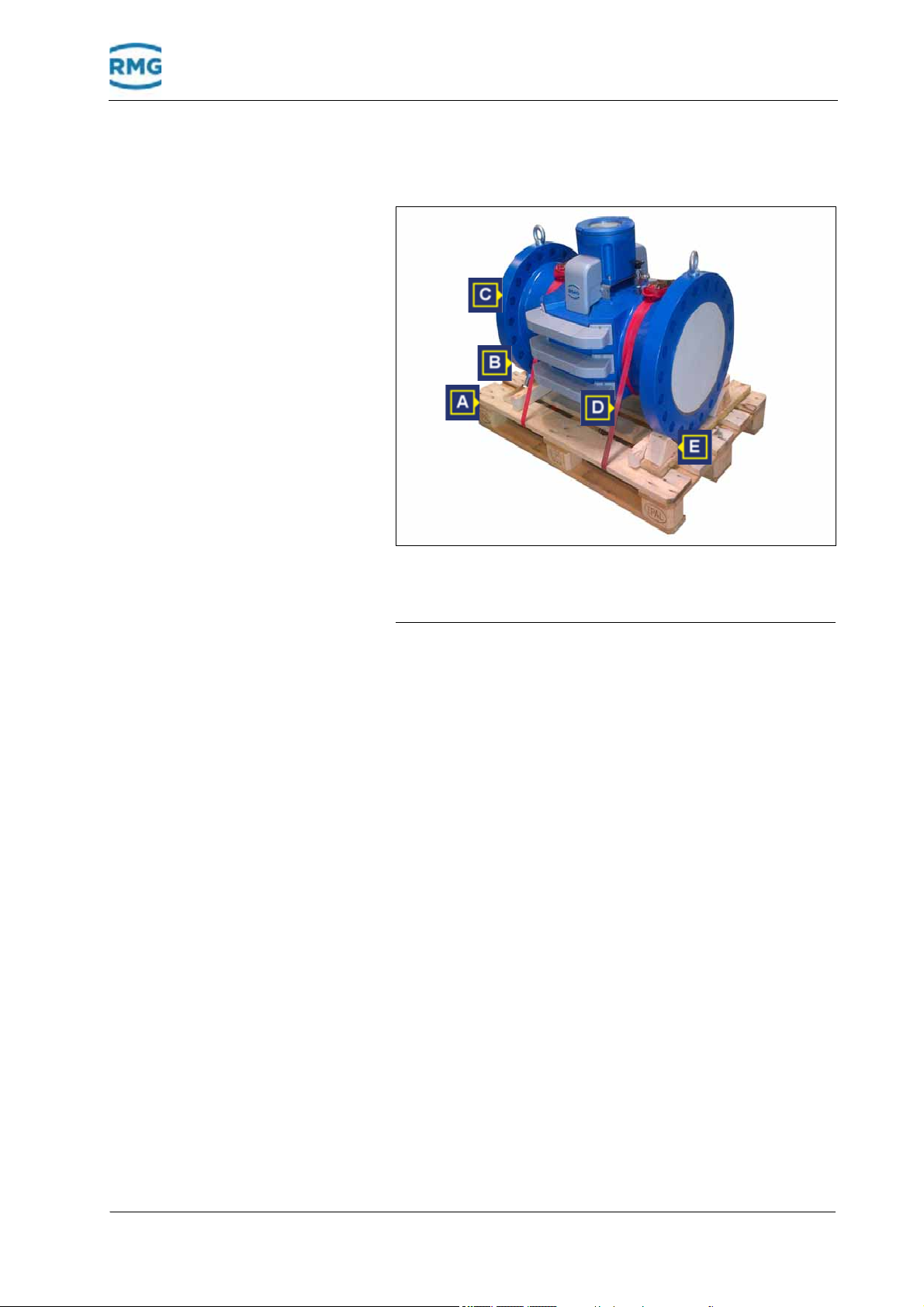
6 Transport and storage
6.1.2
Transporting the device
A Euro pallet B Retaining bolts x 2
C Ultrasonic gas meter D Retaining strap x 2
E Timber wedge x 2
6.1.3
Fig. 6-1: Device secured on a Euro pallet
The device is as standard supplied on a Euro pallet (A). The device can be protected by a customer-specific outer packaging. To
secure the devic
device (C) is supplied with retaining straps (D) and bolted to timber wed
addition
The device can be transported on the pallet using a lifting cart or
a fork lift.
ges (E). The retaining bolts (B) of the device provide
al support.
Unpacking the device
Remove the outer packaging
The outer packaging of the device is suite
cifics in order to protect the de
influences from the environment during transport.
Options for the outer packaging
• sea-proof wooden crate
• cardboard packagings
e against tipping-over and rolling away, the
d to customer spe-
vice against damage or
can be, for example:
1 Remove the outer packing.
September, 4th 2018 Ultrasonic Flowmeter USM GT400 49

6 Transport and storage
2 Recommendation: store the outer packaging for the future or
for returning to RMG for service work.
A Retaining bolts
Fig. 6-2: Retaining bolts of the device
3 Make sure that the retaining bolts (A) are screwed in, if
necessary.
50 Ultrasonic Flowmeter USM GT400 September, 4th 2018

6 Transport and storage
Warning
!
Removing the device from the Euro pallet
A Lifting eyes B Lifting gear chains
Fig. 6-3: Attaching the lifting gear
Risk of injury during transport
The device may be damaged when lifting and putting down, tipping
over or falling down. By disregarding the load bearing capacity of the
lifting gear, the device may fall. There is a risk of severe injuries for
persons in the vicinity.
tended
• Lift the device only on the in
• Before lifting, make sure that the load is safely secured.
• Never stand under suspended loads.
• Observe the weight specifications for the ultrasonic gas me
hand.
lifting eyes.
ter at
1 Attach a suitable lifting gear (B) to the lifting eyes (A) of the
device.
2 Tension the chain of the lifting gear slig
htly to secure the
device.
September, 4th 2018 Ultrasonic Flowmeter USM GT400 51
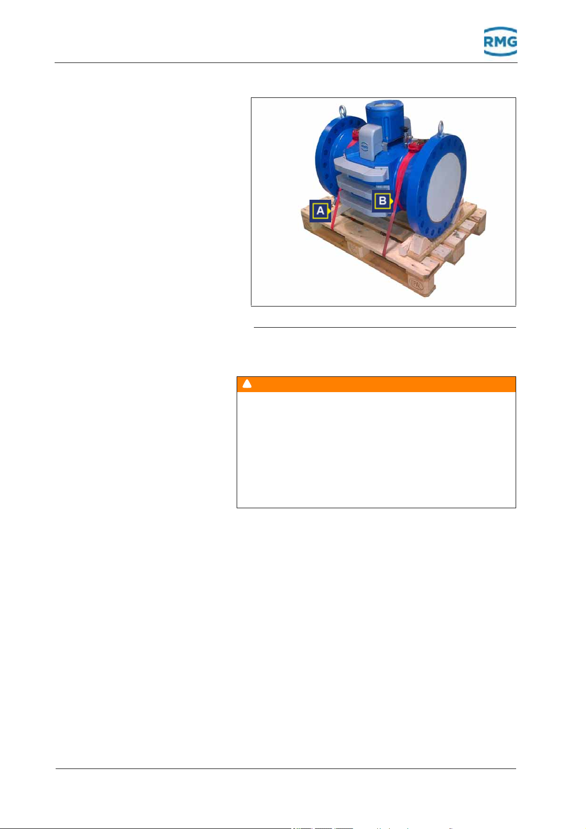
6 Transport and storage
Warning
!
A Timber wedge B Tension straps
Fig. 6-4: Remove the timber wedges and retaining straps
3 Undo and remove the tension straps (B).
Risk of injury during transport
The device may be damaged when lifting and putting down, tipping
over or falling down. By disregarding the load bearing capacity of the
lifting gear, the device may fall. There is a risk of severe injuries for
persons in the vicinity.
• Lift the device only on the intend
• Before lifting, make sure that the load is safely secured.
• Never stand under suspended loads.
• Observe the weight specifications for the ultrasonic ga
hand.
ed lifting
eyes.
s meter at
4 Carefully lift the device with a lifting gear until the Euro pallet
can be pulled from underneath the device.
5 Pull the Euro pallet from u
6 Recommendation: store the Euro pallet for t
nder the device.
he future or for
returning to RMG for service work.
52 Ultrasonic Flowmeter USM GT400 September, 4th 2018

6 Transport and storage
Notice
6.1.4
6.1.5
Disposal of packaging material
If the packaging material and the Euro pallet are no longer required, dispose of the material in an environmentally responsible
manne
r according to the country-specific standards and
guidelines.
Prior to installation
The transport locks must only be removed once the device has
been installed in the system and the device has been transported
to the installation location.
Damage to the device from contamination and humidity
If transport locks are removed too early, contamination and humidity
may enter the device. The device could be damaged.
• Disassemble the transport
device.
The following belong to the transport locks:
• Blind plug
• Protective sticker
• Retaining bolts
Re
mmendation: remove the retaining bolts
co
solutely necessary. This is the only way to ensure that the
ab
device does not tip over or roll away after being installed.
• Cor
rosion protection mat
locks immediately before installing the
only if it is
6.1.6
September, 4th 2018 Ultrasonic Flowmeter USM GT400 53
Removing the transporting locks
The removal of the transport locks is described here on the example of a connection or flange. The transport locks also have to
be rem
located.
Removing the pr
oved from all connections where the transport locks are
otective sticker / blind plugs from the
flanges
The flanges are supplied sealed with a protective sticker
blind plug made of plastic.
or

6 Transport and storage
Removing the protective sticker
A Protective sticker B Flange
Fig. 6-5: Removing the protective sticker
1 Release the protective sticker from the sealing surface of the
flange.
2 Remove any residual adhesives or other impu
sealing surfaces of the flange using a gentle cleaning agent.
Remove the blind plugs 1 Pull the blind plugs out of the openings.
rities from the
54 Ultrasonic Flowmeter USM GT400 September, 4th 2018

6 Transport and storage
Remove the corrosion protection mat
The inside of the device is protected using
tection mat. The corrosion protection mat must be
before installation.
A Position of the corrosion protection mat
Fig. 6-6: Corrosion protection mat in the device
a corrosion pro-
removed
6.2
1 Remove the corrosion protection mat (A) from the device.
Packing the device for transportation
The device must be packed to customer-specifics according to
the transport requirements. In this chapter you will receive information as to how the device is as standar
For packaging, use the original packaging mater
set that was supplied with the device.
If you no longer have the original packaging material and sealing
set, you ca
quired from RMG.
RMG service would be pleased to consult you as to how the device should be packed.
You need the following for standard packaging:
• Euro pallet with timber wedges (with the original packaging,
the timber
pallet).
• T
• Transport locks
• Sealing set (blind plugs)
n order the packaging material and sealing set re-
wedges are already pre-mounted on the Euro
wo tensioning straps
d packed.
ial and sealing
September, 4th 2018 Ultrasonic Flowmeter USM GT400 55

6 Transport and storage
Caution
!
• Acid-free corrosion protection agent, e.g., ESSO RUST BAN
397, Mobil Oil Tecrex 39
Ensure for a safe position of the device
Risk of injury from missing retaining bolts
If the device is put down without the retaining bolts, it can tip over or
roll away. Servere injuries may occur.
• Before starting work, make sure that the retaining bolts are screwed
in.
A Retaining bolts with counter-nuts
Fig. 6-7: Check the retaining bolts
The retaining bolts are screwed into the device ex-factory.
These ensure for a safe position.
1 Make sure that the retaining bolts are screwed in and that the
counter
-nuts are secured.
Recommendation: remove the retaining bolts only if it is
absolutely neces
sary. This is the only way to ensure that the
device does not tip over or roll away after being installed.
56 Ultrasonic Flowmeter USM GT400 September, 4th 2018

6 Transport and storage
Warning
!
Lifting the device onto the Euro pallet
A Lifting eyes B Lifting gear chains
Fig. 6-8: Attaching the lifting gear
Risk of injury during transport
The device may be damaged when lifting and putting down, tipping
over or falling down. By disregarding the load bearing capacity of the
lifting gear, the device may fall. There is a risk of severe injuries for
persons in the vicinity.
tended
• Lift the device only on the in
• Before lifting, make sure that the load is safely secured.
• Never stand under suspended loads.
• Observe the weight specifications for the ultrasonic gas me
hand.
lifting eyes.
ter at
1 Attach a suitable lifting gear (B) to the lifting eyes (A) of the
device.
2 Tension the chain of the lifting gear slig
htly.
3 Undo the bolted connections from the system so that the
vice can be lifted out.
de
September, 4th 2018 Ultrasonic Flowmeter USM GT400 57

6 Transport and storage
Warning
!
A Retaining bolts B Tension straps
C Timber wedge
Fig. 6-9: Secure the device on the Euro pallet
4 Place the Euro pallet under the device.
Without the retaining bolts (A) the flange must be guided
en the timber wedges (C).
betwe
Risk of injury during transport
The device may be damaged when lifting and putting down, tipping
over or falling down. By disregarding the load bearing capacity of the
lifting gear, the device may fall. There is a risk of severe injuries for
persons in the vicinity.
• Lift the device only on the intended lifting
• Before lifting, make sure that the load i
• Never stand under suspended loads.
• Observe the weight specifications for the ultrasonic ga
hand.
eyes.
s safely secured.
s meter at
5 Carefully place the device on the Euro pallet with the lifting
gear.
6 Secure the device using the tensioning straps (B).
e tensioning straps must have
Th
a tight fit and must secure
the device.
58 Ultrasonic Flowmeter USM GT400 September, 4th 2018

6 Transport and storage
Notice
Place the corrosion protection mat inside the device
Damage to the device from corrosion
If the device is not protected against corrosion, the function of the
device may be affected.
• Place the corrosion protection mat inside the devi
ce.
A Position of the corrosion protection mat
Fig. 6-10: Corrosion protection mat in the device.
1 Clean the device and protect all blank parts against corrosion
with an acid-free corrosion protection agent, e.g., ESSO
RUST BAN 397, Mobil Oil Tecrex 39.
Chapter 11.7, „Cleaning the device“ on page 148
2 Place the corrosion protection mat (A
) inside the device.
September, 4th 2018 Ultrasonic Flowmeter USM GT400 59

6 Transport and storage
Provide the connection box (ATEX / IECEx) with blind
plugs
A Wrench B Screwed cable gland
C Blind plug
Fig. 6-11: Mount the blind plugs
1 Insert the blind plugs (C) into the connection.
2 Tighten the screw connection (B) with a suitable wr
The following sealing bolts supplied must be used in countries
where CSA / FM guidelines apply. If only transport is taking place,
you can use 1/2" or 1" screws with appropriate length as an
alternative.
ench (A).
60 Ultrasonic Flowmeter USM GT400 September, 4th 2018

6 Transport and storage
Applying the protective sticker / blind plugs to the
flanges
Sealing the flange with protective
st
ickers
The flanges must be sealed with a protective sticke
plug made of plastic.
A Protective sticker B Flange
Fig. 6-12: Applying the protective sticker
1 Clean the sealing area with grease remover.
r or blind
Sealing the flange wit
The sealing surface must be free of grease and
contamination.
ick the protective sticker (A) onto the sealing surface
2 St
flange (B).
h blind plugs 1 Inser
the blind plugs have a tight fit.
of the
t the blind plugs into the opening of the flange so that
September, 4th 2018 Ultrasonic Flowmeter USM GT400 61

6 Transport and storage
Notice
Danger
!
Applying the outer packaging to the device
Damage caused to the device from incorrect storage / transport
If the device is not protected correctly by the packaging material, dirt
or humidity may enter the device and damage it.
• Pack the device according to the instruction.
Consider the special transport requirements on the packaging mate-
•
rial, e.g., for transpor
• Please contact RMG service in case of doubt.
Use the original packaging that was supplied along with the
device. Please contact RMG service if you have any
questions.
Options for the outer packaging can be, for example:
• sea-proof wooden crate
• cardboard packagings
t overseas.
6.3
Storage
1 Protect the device in the outer packaging against environ-
mental influences.
In this chapter you will receive information on the correct storage
of the device. You are also provided with information that must be
observed when storing for long periods.
Mortal danger from damage in the warehouse
If the device is stored for longer than one year, the device may be
damaged from incorrect outer packaging or securing of the device. In
potentially explosive environment, a defective device may lead to an
explosion. Danger of poisoning!
• Avoid long storage times.
ice if
• Have the device checked by RMG serv
ger than one year. For this purpose, send
the storage time is lon-
the device to RMG.
62 Ultrasonic Flowmeter USM GT400 September, 4th 2018

6 Transport and storage
Notice
Danger
!
6.3.1
6.3.2
Packing the device for storage
Damage caused to the device from incorrect storage / transport
If the device is not protected correctly by the packaging material, dirt
or humidity may enter the device and damage it.
• Pack the device according to the in
• Consider the special transport requirements on the packaging material, e.g., for transport overseas.
• Please contact RMG service in case of dou
1 Packing the device.
„Packing the device for transportation“ on page 55
2 Observe the approved ambient temperature for storage.
Chapter 13.1, „Performance data“ on page 160
Checking the device after storage
Mortal danger from damage in the warehouse
If the device is stored for longer than one year, the device may be
damaged from incorrect outer packaging or securing of the device. In
potentially explosive environment, a defective device may lead to an
explosion. Danger of poisoning!
• Avoid longer storage times.
• Have the device checked by RMG service if the
ger than one year. For this purpose, send the device to RMG.
struction.
bt.
storage
time is lon-
Checking the device for any signs of damage
There is a high risk to life and limb if a dam
aged device is
used.
The following damage can compromise safety and the function of the device:
• notches on the flange sealing su
rfaces
• corrosion in the device or on the sealing surfaces
• cracked glass of the viewing window
• clouded glass of the viewing window
• cracks, flaking on the housing
he covers
or t
• flaking paint
1 Check that the device is intact by
If you discover that there is, e.g., any d
age to the device, the device may only b
a visual inspection.
amage or other dam-
e re-used after
consulting RMG.
2 If damaged: please contact RMG services.
September, 4th 2018 Ultrasonic Flowmeter USM GT400 63

6 Transport and storage
64 Ultrasonic Flowmeter USM GT400 September, 4th 2018

7 Construction and Planning
7
Construction and Planning
In this chapter you will receive information on how you can integrate the device into the system and what you have
during this process.
Contents 7.
7.1 Connection flanges ........................................... 65
7.2 Seals
7.2.1 Flat seal .................................................................. 67
7.2.2 Grooved gaskets
7.2.3 Spiral seals
7.3 Screws ................................................................ 70
7.4 Installation possibilities
7.4.1 Dependency on the gas flow direction ................... 71
7.4.2 Two devices series connecte
................................................................... 66
.................................................... 68
............................................................. 69
.................................... 71
d (Face to Face) ....... 74
to observe
7.1
7.5 Flow computer ................................................... 75
Connection flanges
The devices from RMG are equipped with connection flanges.
The joining dimensions of the flanges for the pipelines to be connected must correspond to the con
device flanges.
• ANSI
• DIN press
pressure stages: The flange joining dimensions comply
the standard ASME B 16.5.
with
re stages: The flange joining dimensions comply
u
with the standard DIN EN 1092.
nection dimensions of the
September, 4th 2018 Ultrasonic Flowmeter USM GT400 65

7 Construction and Planning
Danger
!
Notice
7.2
Seals
Escaping gas from incorrect seals
If incorrect flange seals are used for several ultrasonic gas meters,
potentially explosive gas mixtures can escape due to leaks. Risk of
intoxication and explosion! Moreover, the pressure of the flange
increases with the improper tightening of the screw bolt.
• Make sure that the flat seal does
face into the pipeline.
Malfunctions from incorrect seals
If flange seals are used for ultrasonic gas meters that protrude into the
pipeline, the measuring accuracy may be influenced.
• Make sure that the flat seal does
face into the pipeline.
The durability of the flange connections has been verified for
seals with the following maximum material values according to
the AD2000 regulations.
Flat seals: k0 x KD = 20 x bD | k1 = 1.3 x bD (N/mm)
not protrude over the sealing sur-
not protrude over the sealing sur-
Grooved gaskets: k0 x KD = 15 x bD | k1 = 1.1 x bD (N/mm)
Spiral seals: k0 x KD = 50 x bD | k1 = 1.4 x bD (N/mm)
Octagonal ringjoint seal::
KD = 480 N/mm
2
66 Ultrasonic Flowmeter USM GT400 September, 4th 2018

7 Construction and Planning
7.2.1
DN
in mm (inch)
80 (3) 90 (3.54)
Flat seal
d1
in mm (inch)
89 (3.5)/ANSI150
Fig. 7-1: Dimensions of the seal
d1 = Inside diameter
d2 = Outside diameter
x = Seal thickness 1.5 to 5 mm
PN 10 PN 16 ANSI 150 PN 25 PN 40
d2
in mm (inch)
142 (5.59) 142 (5.59) 136.5 (5.37) 142 (5.59) 142 (5.59)
100 (4) 115 (4.53) 162 (6.38) 162 (6.38) 175 (6.89) 168 (6.61) 168 (6.61)
150 (6) 169 (6.65) 218 (8.58) 218 (8.58) 222 (8.74) 225 (8.86)
200 (8) 220 (8.66) 273 (10.75) 273 (10.75) 279 (10.98) 285 (11.22) 292 (11.52)
250 (10) 274 (10.79) 328 (12.91) 330 (12.99) 340 (13.39) 342 (13.46)
300 (12) 325 (12.80) 378 (14.88) 385 (15.16) 410 (16.14) 402 (15.83) 418 (16.46)
400 (16) 420 (16.54) 490 (19.29) 497 (19.57) 514 (20.24) 515 (20.28)
500 (20) 520 (20.47) 595 (23.43) 618 (24.33) 607 (23.90) 625 (24.61) 628 (24.72)
600 (24) 620 (24.41) 695 (27.36) 735 (28.94) 718 (28.27) 730 (28.74) 745 (29.33)
225 (8.86)
353 (13.90)
547 (21.54)
September, 4th 2018 Ultrasonic Flowmeter USM GT400 67

7 Construction and Planning
7.2.2
Grooved gaskets
Fig. 7-2: Dimensions of the seal
d1 = Inside diameter
d2 = Outside diameter
x = Seal thickness 1.5 to 5 mm
ANSI 300 / ANSI 600 PN 64
DN
in mm (inch)
80 (3) 98.4 123.8 95 121
100 (4) 123.8 154.0 11 8 144
150 (6) 177.8 221.7 170
d1
in mm
d2
in mm
d1
in mm
d2
in mm
204
200 (8) 228.6 266.7 220 258
250 (10) 282.6 320.7 270
300 (12) 339.7 377.8 320 365
400 (16) 422.3 466.7 426
500 (20) 530.2 581.0 530 578
600 (24) 631.8 682.6 630 680
315
474
68 Ultrasonic Flowmeter USM GT400 September, 4th 2018

7 Construction and Planning
7.2.3
DN
in mm
(inch)
80
(3)
Spiral seals
Fig. 7-3: Dimensions of the seal
d1 = Inside diameter of the centering ring
d2 =Inside diameter of the seal
d2 = Outside diameter
x = Seal thickness 1.5 to 5 mm
ANSI 300 PN 64 ANSI 600
d1
in mm
(inch)
81
(3.19)
d2
in mm
(inch)
101.6
(3.98)
d3
in mm
(inch)
120.7
(4.75)
d1
in mm
(inch)
86
(3.39)
d2
in mm
(inch)
95
(3.74)
d3
in mm
(inch)
119
(4.69)
d1
in mm
(inch)
81
(3.19)
d2
in mm
(inch)
101.6
(3.98)
d3
in mm
h)
(inc
120.7
(4.75)
100
(4)
150
(6)
200
(8)
250
(10)
300
(12)
400
(16)
500
(20)
600
(24)
106.4
(4.19)
157.2
(6.19)
215.9
(8.5)
268.
(10.6)
317.5
(12.5)
400
5.7)
(1
500
(19.7)
603.
(23.8)
3
3
127.0
(5.00)
182.6
(7.19)
233.4
(9.19)
287.3
(11.31)
339.9
(13.38)
422.4
(16.63)
525.5
(20.69)
628.7
(24.75)
149.4
(5.88)
209.6
(8.25)
263.7
(10.38)
317.5
(12.50)
374.7
(14.75)
463.6
(18.25)
577.9
(22.75)
685.8
(27.00)
108
(4.25)
162
(6.38)
213
(8.39)
267
(10.5)
318
(12.5)
414
(16.3)
518
(20.4)
618
(24.3)
120
(4.72)
174
(6.85)
225
(8.86)
279
(10.98)
330
(12.99)
426
(16.77)
530
(20.87)
630
(24.80)
144
(5.67)
0
20
(7.87)
257
(10.12)
315
(12.40)
366
(14.41)
466
(18.35)
574
(22.60)
674
(26.54)
120.7
(4.75)
174.8
(6.88)
225.6
(8.88)
274.6
(10.81)
327.2
(12.88)
412.8
(16.25)
520.7
(20.50)
628.7
(24.75)
120.7
(4.75)
174.8
(6.88)
225.6
(8.88)
274.6
(10.81)
327.2
(12.88)
412.8
(16.25)
520.7
(20.5)
628.7
(24.75)
149.4
(5.88)
209.6
(8.25)
263.7
(10.38)
317.5
(12.50)
374.7
(14.75)
463.6
(18.25)
577.9
(22.75)
685.8
(27.00)
September, 4th 2018 Ultrasonic Flowmeter USM GT400 69

7 Construction and Planning
Notice
7.3
Screws
Temperature range for bolts and nuts
-40°C to +80°C
Pressure stages Version 1 Version 2 Version 3
PN10, PN16,
PN25, PN40,
PN64
Bolts according to
DIN EN ISO 4014
of
material 25CrMo4, nuts
–
–
according to
DIN EN ISO 4032 of
rMo4
20 Grade L7,
rding to
20 Grade
L7
Bolts according to
ANSI B1.1 of material
42CrMo4
, nuts according to ANSI B1.1 of material 42CrMo4
Bolts with reduced shank
according to DIN 2510 of
materia
according to DIN 2510 of
materia
ANSI150,
ANSI300,
ANSI600
material 25C
Bolts according to
ANSI B1.1 of material
ASTM A 3
nuts acco
ANSI B1.1 of material
ASTM A 3
The stability of the flange connection was verified using the
screws list
ed above in conjunction with the seals listed in
Chapter 7.2. Other screw / flange versions have not been
inspected.
l 25CrMo4, nuts
l 25CrMo4
Variant 3 bolts with reduced shank may
only be used for devices
within the area of PED (Pressure Equipment Directive)
application.
DN80
Screws are provided by RMG for the USM-GT400 for diameter DN80.
Depending on the flange type the following hexagonal bolts are
used for DN80:
PN16/10 PN40/25 PN64 ANSI150 ANSI300 ANSI600
DIN EN 24014
(DIN931 ISO4014)
M16 x 48 – 8.8
L=48 mm or material: 25CrMo4
galvanized
*1
*2
DIN EN 24014
(DIN931
M16 x 52 – 8.8
L=52 mm or material: 25CrMo4
galvanized
ISO4014)
*2
DIN EN 24014
(DIN931 ISO4014)
*1
M16 x 56 – 8.8
L=56 mm or material: 25CrMo4
galvanized
5/8“ - 11 UNC
2A x 2 1/8“
*1
L=54mm (2 1/8“)
A320 Grade7
UNC
*2
*1
These screws can only be used down to -10°C.
*2
These screws can be used down to -46°C.
or material:
42CrMo4 galva-
*2
nized
3/4“ - 10 UNC
2A x 2 1/4“
L=54mm (2 1/4“)
A320 Grade7
UNC
or material:
42CrMo4 galva-
*2
nized
3/4“ - 10 UNC
2A x 2 5/8“
L=54mm (2 5/8“)
UNC A320
or material:
42CrMo4 galva-
*2
nized
Grade7
70 Ultrasonic Flowmeter USM GT400 September, 4th 2018

7 Construction and Planning
7.4
7.4.1
Installation possibilities
You have different possibilities when installing the device into
your system. Please verify a proper inner diameter of any pipe
that is connected to the meter.
–See „Inner diameter of connecting spool pieces“ on
page 168
Dependency on the gas flow direction
In order for the installation to correspond to the requirements of
the Measurement Instrument Directive 2004/22/EC (MID) or
Measurement Canada (MC), the device must be installed with an
inlet and outlet piping.
With this installation, the device can be used for
surements and for secondary measurements.
Unidirectional operation
calibrated mea-
A Temperature sensor
Fig. 7-4: Unidirectional operation
September, 4th 2018 Ultrasonic Flowmeter USM GT400 71

7 Construction and Planning
A Flow conditioner B Temperature sensor
Fig. 7-5: Unidirectional operation - compact installation
72 Ultrasonic Flowmeter USM GT400 September, 4th 2018
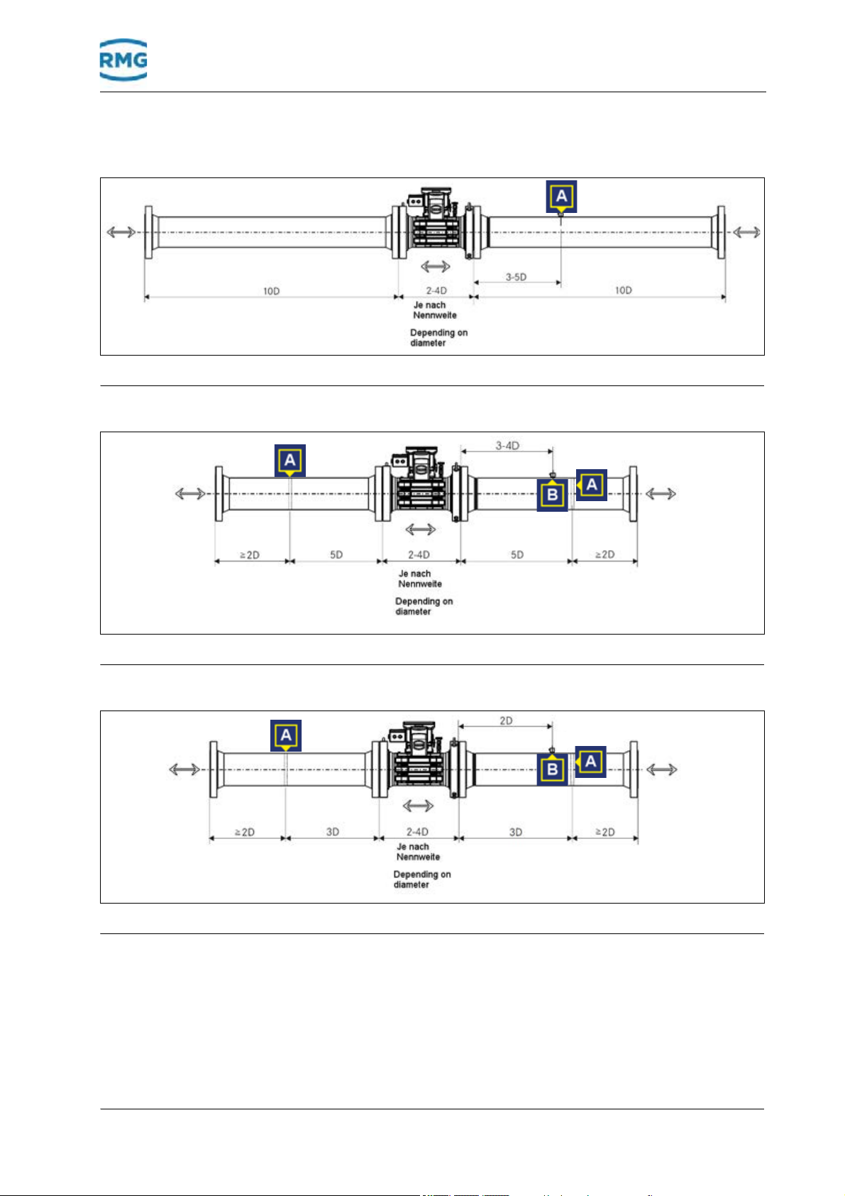
A Temperature sensor
Fig. 7-6: Bidirectional operation
7 Construction and Planning
Bidirectional operation
A Flow conditioner B Temperature sensor
Fig. 7-7: Bidirectional operation - compact installation < DN 300 (12")
A Flow conditioner B Temperature sensor
Fig. 7-8: Bidirectional operation - compact installation DN 300 (12")
September, 4th 2018 Ultrasonic Flowmeter USM GT400 73

7 Construction and Planning
Notice
Notice
7.4.2
Two devices series connected (Face to Face)
You can install one or several devices in series.
Malfunctions from pairing the devices incorrectly
If the devices do not match one-another for these installation possibilities, incorrect measurements may occur.
• Please consult RMG if a Face-to-Face installation is possible with
the desired devices and number of devices.
A Tapered bore B Inner diameter
Fig. 7-9: Face-to-Face installation
With this installation option, two or several devices are connected
with one-another via the flanges. Third-party manufacturer devices can also be connected to RMG devices.
For this purpose, a tapered bore can be applied to the flanges on
the inlet and outlet piping.
The
flanges that are used to connect the devices with one-another do not require a tapering. For third-party manufacturer devices,
you have to check if a tape
For the device with the smaller inner diameter it is mandatory to use a
tapering.
If two RMG devices are connected with one-another, the inner diameter must be continuously the same. Different siz
cannot be connected to one-another.
ring is required.
ed devices
74 Ultrasonic Flowmeter USM GT400 September, 4th 2018

7 Construction and Planning
7.5
Flow computer
If required, you can connect one or two flow computers to the
device.
Follow the installation g
Operating instructions of the flow computer
Th
e 2 interfaces RS485-1 and RS485-2 have the same features
and you ma
However, the RS 485-1 (in contrary
permit a parameterizable byte sequence for the data types Long
and Float. We therefore recommend that you use the RS 485-1
for the DZU protocol and the RS 485-2 for instance F communication. You may find more in
Flow computer from RMG The device is compatible with the following flow computer series
from RMG
• ER
• ERZ 24
If you want to use the flow computer from RMG specified above,
do not have to carry out any configurations. The flow comput-
you
ers from RMG can directly process the
gas meter from RMG directly. For this purpose, the flow computer
has to be connected to the digital interface RS485-1 in order to
allow all diagnosis functions to be used. If you want to install an
additional flow computer for reasons of security, this must be connected via the interface RS485-2.
y change in the following1 to 2 (and 2 to 1) freely.
:
00 NG
Z 20
00
uidelines of the flow computer:
to the RS 485-2) does not
rmation in chapter 8.3.
fo
protocol of the ultrasonic
Flow computer from third-party
manufacturer
September, 4th 2018 Ultrasonic Flowmeter USM GT400 75
Flow computers from third-party manufacturers can be connected to the device. These can only be conn
interface RS485-2. This interface communicates via a Modbus
protocol. In order to be able to use all diagnosis functions, the
Modbus must be configured. You can also use the high-frequency outputs pulse 1 and 2. When par
the maximum possible gas flow rate correlates to a maximum frequency of 2 kHz. All diagnosis functions cann
interface.
If you are using a third-party manu
configure the flow computer.
ected to the digit
meterizing, take care that
a
ot be used via this
facturer device, you have to
al

7 Construction and Planning
Explosive atmospheres
Device group II zone 1
Maximum distance 500 m / 1640 ft
Safe area
or
Class1, Division1
Connecting a flow computer for example an ERZ2000 / ERZ2400
Fig. 7-10: Connection diagram for connection of a flow computer fo r example an ERZ2000 / ERZ2400
The cable length must not exceed a length of 500 meters /
1640 feet.
More information on the installation
found here:
Oper
ating instructions of the flow computer
of a flow computer can be
76 Ultrasonic Flowmeter USM GT400 September, 4th 2018

8 Installation
8
Installation
In this chapter you are provided with information on how you can
correctly install the device and what you have to observe during
the process.
The tasks of the chapter described must only be carried out by
trained and certified personal.
Content 8.
8.1 Assembly work preparations ............................ 78
8.2 Installation of the device
8.2.1 Mounting the inlet and outlet piping ........................ 80
8.2.2 Installation of the connection box
8.3 Connecting the device electrically ................... 84
8.3.1 Connecting the power supply ................................. 89
8.3.2 Digital interfaces of USM-GT400
8.3.3 Connecting the computer for RMGView
8.3.4 Connecting the flow computer
8.3.5 Connection of external DSfG
8.3.6 Interface converter
8.3.7 Connecting the device to earth
95
................................... 80
........................... 81
............................ 90
USM
.......... 91
................................ 92
-Device-F via Modbus ....
............................................... 108
............................. 110
8.4 Installing the pressure connection ................ 112
8.5 Outdoor installation
September, 4th 2018 Ultrasonic Flowmeter USM GT400 77
......................................... 114

8 Installation
Danger
!
Warning
!
Caution
!
8.1
Assembly work preparations
Mortal danger from electric current
In potentially explosive environments, dangerous voltages can still
remain as ignition sources for up to one minute after being switched
off.
• Disconnect the device from the power supply before star
maintenance work.
• Secure the device against being switched back on.
• Cordon-off the work area of the device, e.g., using a b
signs.
• After switching off the device, wait at least one minute before starting work. Ensure that the device is volt
earth and short-circuit.
Mortal danger from components under pressure
Flange joining elements, pressure tapping screw conn
valves must not be removed if pressure is applied to the device. Components may be flung-around. Gas escaping may cause intoxication
burns. Risk of explosion!
and
• Carry out work on the device only when it is in a voltage-free state,
is vented and without pressure.
Mortal danger from incorrect work
Hazards can only be recognized and avoid
sonnel. If work is carried out by persons who have not been trained
these special activities in potentially explosive areas, they may cause
an explosion.
• Have installations only carried out by especia
(expert according to DIN VDE 0105, IEC 364 or similar national
standards).
Mortal danger from damaged sealing surfaces
If sealing surfaces are damaged, e.g., from notches or scratch
leaks may occur. Risk of intoxication and explosion!
• Install only an undamaged device.
age-free. Then connect to
ed by specially trained per-
ting the
arrier and
ections and
for
lly trained personnel
es,
Risk of injury during transport
The device may be damaged when lifting and putting down, tipping
over or falling down. By disregarding the load bearing capacity of the
lifting gear, the device may fall. There is a risk of severe injuries for
persons in the vicinity.
• Lift the device only on the intend
• Before lifting, make sure that the load is safely secured.
• Never stand under suspended loads.
• Observe the weight specifications for the ultrasonic ga
hand.
Risk of injury from missing retaining bolts
If the device is put down without the retaining bolts, it can tip over or
roll away. Serious injuries may occur.
• Before starting work, make sure that the retaining bolts are screwed
in.
ed lifting
eyes.
s meter at
78 Ultrasonic Flowmeter USM GT400 September, 4th 2018

8 Installation
Notice
Damage to the device when used as a climbing aid
If the device is used as a climbing aid, components may be damaged.
•Do not use the device as a climbi
• Use a suitable non-slip step that allows you to easily and safely
reach the components.
Carry out preparatory work
1 Unpack the device.
Chapter 6.1.3, „Unpacking the device“ on page 49
ng aid.
For ATEX / IECEx
2 Remove the transporting lock
Chapte
r 6.1.6, „Removing the transporting locks“ on
s.
page 53
A Wrench B Screwed cable gland
C Blind plug
Fig. 8-1: Remove the blind plugs
3 Unscrew connection (B) with a suitable wrench (A).
4 Pull the blind plugs (C) out of the connection.
5 Scre
w glandes not required must be r
eplaced by explosion-
proof screw connections.
Recommendation: store the blind plugs for the future or fo
r
returning to RMG for service work.
September, 4th 2018 Ultrasonic Flowmeter USM GT400 79

8 Installation
Danger
!
For NEC 500 In countries where CSA / FM guidelines apply, the connec-
tions not required must be provided with gask
factory. Please leave these in the screw connection and only
connect the cable that leaves the conduit seal. When joining
the conduits to the flame block, ensure for a slight gradient
away from the flame block in order to avoid the accumulation
of water on the conduit seal. Moreover, also ensure that you
do not twist the conduit seal when securing the conduit as the
cable in the electrics housing may tear-off as a result. If necessary, use a respective bolted connection (union).
et screws ex-
8.2
8.2.1
For all devices 6 Secure the device with r
Chapter 6.2, „Ensure for a safe position of the device“ on
page 56
7 Check the device for any signs of damage.
Chapter 6.3.2, „Checking the device for any signs of dam-
age“ on page 63
8 Clean the sealing surface of the flange from c
with a gentle cle
aning agent.
etainin
Installation of the device
Mounting the inlet and outlet piping
Escaping gas from incorrect seals
If flange seals are used for ultrasonic gas meters that protrude into the
pipeline, potentially explosive gas mixtures may escape due to leaks.
Risk of intoxication and explosion!
• Make sure that the flat seal does
face into the pipeline.
not protrude over the sealing sur-
g bolts for the installation.
ontamination
Observe the instructions for the dimensions!
Chapter 13.5,„Weights and dimensions“ on page 163
80 Ultrasonic Flowmeter USM GT400 September, 4th 2018

8 Installation
Notice
A Inlet piping B Ultrasonic gas meter
C Outlet piping
Fig. 8-2: Installation of the Inlet and outlet piping
The bolted connection of Inlet (A) and outlet piping (C) must be
tightened according to the tightening torque of the plant manufacturer. The tightening torque must comply with the bolts and seals
used.
8.2.2
1 Clean
2 Tighten the bolts cross-wise in order to avoid tensioning.
In general, only the horizontal installation of the USM GT400 is
strongly recommended. Turning the meter by more than 2 flange
holes should not be used to avoid the collection of condensate in the
sensor pockets. Only in dry and clean gas, other installation positions
might be possible also, but it is not recommendable.
the sealing surface of the flang
with a gentle cleaning agent.
Installation of the connection box
The device can be ordered in different versions. Depending on
the version ordered, another procedure must be carried out for
the installation.
These are the order versions:
• conn
• conn
ection box according to ATEX / IECEx
„Installatio
page 82
ection according to NEC 500
no
box must be installed here, only connect the cable accord-
ing to their designation.
Cable
page 84
n of the connection box (ATEX / IECEx)“ on
connection „Connecting
e from contamination
the device electrically“ on
September, 4th 2018 Ultrasonic Flowmeter USM GT400 81

8 Installation
Installation of the connection box (ATEX / IECEx)
A Connection box Ex-de
Fig. 8-3: Connecting the connection box
This version of the connection box is supplied in countries where
the ATEX / IECEx standards apply.
The external connecting housing is pre-assembled and connected electrically to the ultr
asonic electronics ex-factory.
82 Ultrasonic Flowmeter USM GT400 September, 4th 2018

Open the connection box (Ex-de)
8 Installation
A Cover B Screws
C Screwdriver
Fig. 8-4: Opening the connection box cover
1 Unscrew the screws (B) using a suitable screwdriver (C).
2 Remove cover (A).
Closing the connection box (Ex-de)
1 Place cover (A) onto the connection box.
2 Screw in the sc
rews (B) using a suitable screwdriver (C).
Joining the device to the customers flameproof connection box
With this order version, no connection box is mounted on the
device.
The device offers the connection by cable that are routed through
flame block. The wiring in the ultrasonic electronics is carried
the
out ex-factory. The cables are marked accordingly for connecting
and can be connected in a customer’s connection box.
Observe the following when installing:
• The
• Select a maximum cable length of three meters. If you need
September, 4th 2018 Ultrasonic Flowmeter USM GT400 83
cables must be connected according to t
to use longer cables, pleas
e contact RMG services.
he lettering.

8 Installation
8.3
Connecting the device electrically
In this chapter you will receive information on connecting the
electrical connections.
The terminal strip for the electrical connection is located in the ex-
nal connection box. The terminal assignment and the
ter
markin
gs of the cable are always identical.
Fig. 8-5: Connection assignment on the terminal strip
Maximum assignment The maximum assignment are always completely available for
the connections of the Ex-de connection box.
• Cur
rent / voltage supply (24 VDC)
• Warning message (Warn)
• Alarm message (Alarm)
• Pulse output for "Forwards mode" (
mode" (Pulse 2)
• 2 x dir
• Interface for RMGView
• Interface for an RMG flow comp
• Interface for any flow computer (RS 485 2)
• Anal
• Connection for a pressure sensor as a 2-wire 4-20mA
• Con
og output (4-20 mA)
(AU
1; Terminal 26: [P +] Terminal 27: [P -])
X
nection for a temperature sensor (PT100; AUX2; Terminal 28: [PT100
[PT100 -] Terminal 31: [PT100 -])
Pulse 1
ection detectors for bi-directional operation
USM
(RS 485 0)
uter (RS 485 1)
++], Terminal 29: [PT100 +
) and "Backwards
] Terminal 30:
(I/O1/2)
84 Ultrasonic Flowmeter USM GT400 September, 4th 2018

8 Installation
Cable specification The following cable specifications are according to a complete
assignment of the USM-GT-400 ATEX / IECEx version. The cable types listed are recomme
technically comparable cable types.
ndations that can be replaced by
Power supply
24 VDC
Interface:
RS485-0, RS485-1,
RS485-2
(can be layed in one
cable)
AUX1 LIYCY
AUX2 LIYCY
Analog out: 4..20 mA LIYCY
Warning + alarm LIYCY
Pulse1 + pulse2 + I/
O1+ I/O2
ÖLFLEX® CLASSIC
3 x 1.5 mm²
3 x 2.5 mm
LIYCY (TP)
3 x 2 x 0.75 mm²
2 x 0.75 mm²
2 x 2 x 0.75 mm²
2 x 0.75 mm²
2 x 2 x 0.75 mm²
LIYCY (TP)
4 x 2 x 0.75 mm²
Cable
12.3 mm
13.5 mm
9,4 mm
6.0 mm
8.5 mm
6.0 mm
8.5 mm
10.7 mm
Twisted pair cable (TP) are only required in case of multiple circuits in one cable. Otherwise, LIYCY 2 x 0.75 mm² is sufficient for
all signal outputs.
September, 4th 2018 Ultrasonic Flowmeter USM GT400 85

8 Installation
Connection box according to ATEX / IECEx
A Ex-de for Europe
Fig. 8-6: Close the connection box
In those countries where the standards ATEX and IECEx are valid, the device is supplied
The external connection box is connected
sonic electronics ex-factory and pr
electronics. The external connection box does not have to be
mounted.
with the connection box Ex-de (A).
electrically to the ultra-
e-assembled on the ultrasonic
Connection according to NEC 500
The number of lines that are permitted to be routed through the
cable gland (½" and ¾") on the electrics housing and flame block
is limited. Accordingly, this results in 4 different constellations that
reflect the possibilities for connection.
The numbers given below at each figure o
number of cables; all cables are labeled due to the number of the
basic upper terminal block.
nly counts the limited
86 Ultrasonic Flowmeter USM GT400 September, 4th 2018

8 Installation
Version 1: Minimum assignment - ½" sealing fitting
Fig. 8-7: ½" cable gland with 11 wires, size AWG 18
1 ½" sealing fitting, connected with 11 wires, size AWG 18 (per-
mitted, max. 11; Killark Type ENY-1TM).
For this version, the ERZ 2000 or ERZ 2000 NG cannot
connected via the DZU protocol (RS 485-1).
Version 2: Minimum assignment for bi-directional operation - ¾" sealing fitting
be
Fig. 8-8: ¾" cable gland with 20 wires, si ze AWG 18
2 ¾" sealing fitting, connected with 20 wires, size AWG 18
(permitted, max. 20; Killark Type ENY-2TM).
September, 4th 2018 Ultrasonic Flowmeter USM GT400 87

8 Installation
For bi-directional operation.
For this version, the ERZ 2000 or ERZ 2000 NG cannot be con-
nected via the DZU protocol (RS 485-1).
Version 3: Minimum assignment for operation with
pressure and temperature measurement - ¾" sealing fitting
Fig. 8-9: Measuring with pressure and temperature
For measuring with pressure and temperature:
For this version, the ERZ 2000 or ERZ 2000 NG cannot be con-
nected via the DZU protocol (RS 485-1).
Version 4: Maximum assignment
1/2" and 3/4" sealing fitting
Fig. 8-10: ½“ and ¾“ sealing fittings with up to 31 wires of size AWG 18
88 Ultrasonic Flowmeter USM GT400 September, 4th 2018

8 Installation
3 Connect ¾" sealing fitting with 20 wires of size AWG 18 (per-
mitted, max. 20; Killark type ENY-2TM) and ½" cable gland
with
11 wires of size AWG 18 (permitted, max. 11; Killark type
ENY-1TM).
All connections are routed to th
nected and used.
Not used cables need to be isolated or connected to any unused
free terminals.
e outside
and can be con-
8.3.1
A Power supply
Connecting the power supply
Fig. 8-11: Connection assignment on the terminal strip
1 Connect the power supply to the terminals 24 VDC (A).
Figure 8-16 on page 94
September, 4th 2018 Ultrasonic Flowmeter USM GT400 89

8 Installation
Notice
8.3.2
Fig. 8-12: Dgital interfaces RS485-0 (A), RS 485-1 (B) and RS 485 -2 (C)
Digital interfaces of USM-GT400
The interfaces RS 485-0, RS 485-1 and RS 485-2 are basically
equal and can be set for all possible connections. However, there
are minor differences. These are taken into account in the recommended connections and make it
recommended devices or the PC if they are followed.
ier to connect the
eas
Please use the connections as recommended below.
If connections are used differently additional, extensive settings
may become necessary.
Recommended connections at the digital outputs.
RS 485-1 RS 485-2
IGM-protocol,
DZU-protocol
ERZ2000,
ERZ2400,
Instanz-F,
nd
2
ERZ ...,
Flowcomputer
other suppliers
protocol,
device
RS 485-0
RMGView
(service)
USM
ERZ2000-NG,
ERZ2000-DI
features
no parameterizable byte
sequence for
data types Long
and Float
no parameterizable byte
sequence for
data types Long
and Float
Modbus-Master, can
handle IGM- and
DZU-protocol, too,
parameterizable
byte sequence for
data types Long and
Float
90 Ultrasonic Flowmeter USM GT400 September, 4th 2018

8 Installation
8.3.3
A Service connection
Connecting the computer for RMGView
USM
Fig. 8-13: Connection assignment on the terminal strip
1 Connect the computer to the terminals RS 485-0 (A).
In order to connect, you need an interface converter from
USB to RS
8.3.4).
485. (please see recommendations in chapter
September, 4th 2018 Ultrasonic Flowmeter USM GT400 91

8 Installation
8.3.4
Connecting the flow computer
A Ex-de according to ATEX und
IECEx
Fig. 8-14: Connection box types
The flow computer is connected to the terminal strip of the external connection box (A).
1 Ope
Conne
Connection via data cable for ERZ 2000
Use the following cable:
• twisted pair and shielded cable
• maximum length 500 m / 1640
• line cross-section min. 2 × 2 × 0.75 mm
n the cover of the connection box.
„Open the connection box (Ex-de)“ on page 83
cting the flow computer from RMG
ft
2
92 Ultrasonic Flowmeter USM GT400 September, 4th 2018

8 Installation
A Connection Flow computer 1 B Connection Flow computer 1
Fig. 8-15: Connection assignment on the terminal strip
The 2 interfaces RS485-1 and RS485-2 have the same features
and you may change in the following1 to 2 (and 2 to 1) freely.
1 Connect the first flow computer to the terminals
RS 485-1 (A).
2 Connect the second flow computer to t
RS 485-1 (B).
he terminals
September, 4th 2018 Ultrasonic Flowmeter USM GT400 93

8 Installation
Connecting a flow computer from third-party manufac-
turers
A Connection Warning messages B Connection Warning messages C Connection Pulse 1
D Connection Pulse 2 E Connection RS 485-1 F Connection of S 485-2
Fig. 8-16: Connection assignment on the terminal strip
Flow computers from third-party manufacturers can be connected to RS 485-1 or RS 485-2 terminals. This interface
comm
unicates via a Modbus protocol.
All diagnosis functions can be made available via a configuration
e Modbus.
of th
Flow computers from third-party manufacturers can also be connected to the terminals Pulse 1 and Pulse 2. When
pa
rameterizing, take care that the maximum possible gas flow
rate is assigned to a maximum frequency of 2 kHz. All diagnosis
functions are not available.
1 Connect the flow computer to terminals RS 485-1 (E), RS
48
5-2 (F) or Pulse 1 (C) and 2 (D).
W
arning and alarm messages are also available. You also
have to
operation.
connect a direction contact for bi-directional
2 Connect the terminal Warn (A) fo
3 Connect the terminal Alarm (B) for alarm messages.
94 Ultrasonic Flowmeter USM GT400 September, 4th 2018
r warning messages.

8 Installation
Notice
8.3.5
Connection of external DSfG-Device-F via Modbus
Even though DSfG Device-F (DSfG Instanz-F) is a German standard
the wish for a common connection for different ultrasonic gas flow rate
meters may arise in other countries as well. Therefore this connection
and its treatment is mentioned here, too.
The intension to connect Ultrasonic gas meters comparable to an
electronic evaluations unit via the sam e proto col ari ses due to the
wish to transfer "all" data determined by an ultrasonic gas meter,
i. e. measured values as well as status information or diagnostic
data. Therefore the connection via DSfG-device-F has become
the standard in Germany.
Since the USM GT400 does not have its own DSfG bus access,
its
DSfG-ins
computer, the ERZ 2000-NG, which has this access. To realize
the access the necessary data are transferred between the
ERZ 2000-NG and USM GT400 via Modbus,
ferred to as Instance-F, although it only provides the data
required for DSfG
tance-F protocol is implemented externally via a flow
which is of
Instance-F.
ten re-
September, 4th 2018 Ultrasonic Flowmeter USM GT400 95

8 Installation
Fig. 8-17: Data exchange between ERZ 2000 NG and USM-GT-400
The corresponding settings can be found in the VK Modbus
Master USM menu in the ERZ2000-NG. The corresponding
register expressions can be found in the VJ register expressions
menu. In the USM GT400, the Modbus registers of instance F
are listed in column BA.
Electrical connection
The following figure shows the rear panel of the ERZ2000-NG.
The USM GT400 is connected to the serial interface COM6.
96 Ultrasonic Flowmeter USM GT400 September, 4th 2018
 Loading...