

Page 1
Reliable Measurement of Gas
OPERATING MANUAL
Status: July, 24th 2018
Version: 14 EN
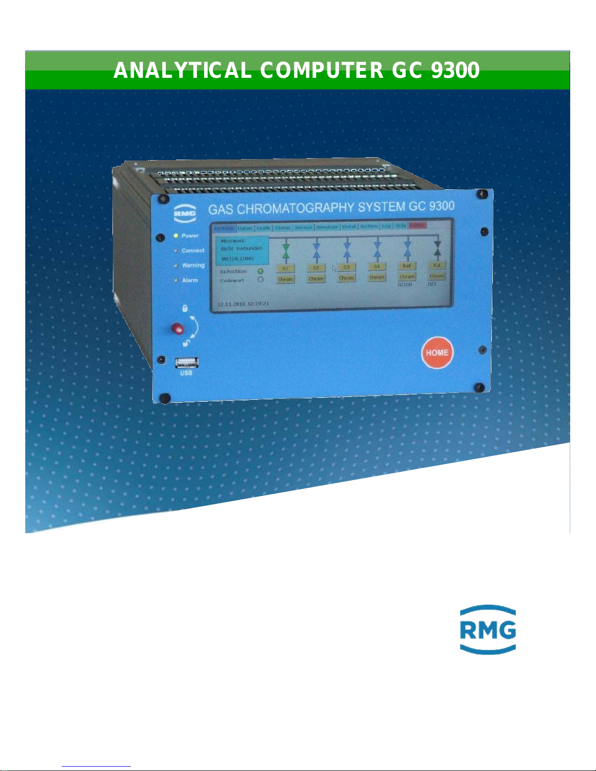
ANALYTICAL COMPUTER GC 9300
Page 2
Contact
Manual GC 9300 EN14 July, 24th 2018
Manufacturer
Contact our customer service department for technical
information.
Address
RMG Messtechnik GmbH
Otto-Hahn-Straße 5
D-35510 Butzbach (Germany)
Main office
+49 6033 897 – 0
Service
+49 6033 897 – 0
Spare parts
+49 6033 897 – 173
Fax
+49 6033 897 – 130
Email
Translation of the
original document
The PGC9300_AC_manual_en_14 for the gas
chromatograph PGC 9300 from July, 24th 2018 is a
translation of the original German manual. Anyhow, this
document may serve as reference for translations into
other languages.
Remark
Please use in case of any uncertainties the German
version as main reference
Note
Unfortunately, paper is not updated automatically,
whereas technical development continuously advances.
Therefore, we reserve the right to make technical
changes in regard to the representations and specifications of these operating instructions. The latest version
of this manual (and the one other devices) can be
downloaded at your convenience from our Internet
page:
www.rmg.com
Created
July 2011
…
…
9. Revised
July 2015
10. Revised
January 2017
11. Revised
June 2017
12. Revised
June 2018
13. Revised
July, 24th 2018
Document version and
language
Document version
PGC9300_AC_manual_en_14
July, 24th 2018
Language
EN
Page 3

Contents
Manual GC 9300 EN14 July, 24th 2018
I
Contents
1 ABOUT THIS MANUAL .................................................................. 1
1.1 Structure of this manual ............................................................................. 1
1.1.1 Abbreviations ......................................................................................................... 1
1.1.2 Symbols ................................................................................................................. 1
1.1.3 Structure of notices................................................................................................ 2
1.1.4 Working with the device ......................................................................................... 3
1.1.5 Risk assessment and minimization ....................................................................... 7
1.1.6 Applicability of the manual ..................................................................................... 8
1.1.7 Transport ............................................................................................................... 9
1.1.8 Scope of delivery ................................................................................................. 10
1.1.9 Disposal of packaging material ............................................................................ 10
1.1.10 Storage ................................................................................................................ 10
1.2 Structure of the manual ............................................................................ 11
1.3 Function ..................................................................................................... 12
1.4 Mode of operation ..................................................................................... 12
1.5 Area of applicability .................................................................................. 13
2 INTRODUCTION ........................................................................... 14
2.1 Touch screen ............................................................................................. 14
2.2 Operation.................................................................................................... 15
2.2.1 Operating modes ................................................................................................. 15
2.3 Data storage ............................................................................................... 17
2.3.1 Archive according to the DSfG standard ............................................................. 18
3 INSTALLATION ............................................................................ 19
3.1 Installation .................................................................................................. 19
3.2 Electrical connections .............................................................................. 19
3.2.1 Connection assignment ....................................................................................... 20
3.2.2 Power supply ....................................................................................................... 23
3.2.3 Interfaces ............................................................................................................. 24
3.2.4 Additional external In- and Outputs ..................................................................... 24
4 COMMISSIONING ........................................................................ 28
4.1.1 Establishing connection to the PC ....................................................................... 28
4.1.2 Switching on the device ....................................................................................... 28
4.2 Gateway GC 9310 ...................................................................................... 28
4.2.1 GC 9310 commissioning ..................................................................................... 30
4.2.2 Interfaces and logs .............................................................................................. 32
4.2.3 Data storage ........................................................................................................ 33
4.2.4 Electrical connections of the GC 9310 ................................................................ 34
Page 4

Contents
Manual GC 9300 EN14 July, 24th 2018
II
5 OPERATION ................................................................................. 39
5.1 Operation on the touch screen ................................................................. 39
5.1.1 Start screen ......................................................................................................... 39
5.1.2 Data: Results of the last analysis ........................................................................ 41
5.1.3 Graph - Trends: Trend display of arbitrary values ............................................... 42
5.1.4 Graph - Chroms: Chromatogram of the last analysis .......................................... 42
5.1.5 Status - Measuring element: Status displays, e.g. column temperature ............. 43
5.1.6 Status – Dig. I/O: Status display of digital inputs and outputs ............................. 44
5.1.7 Service: Service functions ................................................................................... 44
5.1.8 User: User-specific display .................................................................................. 45
5.1.9 Detail: List of all measurements and parameters of the GC 9300 ....................... 46
5.1.10 Archive: Display of archive entries ...................................................................... 47
5.1.11 Log: Display of the log books .............................................................................. 48
5.1.12 DSfG - Archive: Display of the DSfG archive ...................................................... 49
5.1.13 DSfG - Delete: Deletion of the DSfG archive ....................................................... 49
5.1.14 Errors: Display of error messages with date and time ......................................... 50
5.2 Operation examples .................................................................................. 50
5.2.1 Enter code number .............................................................................................. 50
5.2.2 Change operating mode ...................................................................................... 51
5.2.3 Program current output........................................................................................ 52
5.2.4 Read values for maintenance log entry ............................................................... 52
5.3 Bake-out ..................................................................................................... 54
5.3.1 Bake-out process................................................................................................. 54
5.4 View and read archive via internet browser ............................................ 59
5.5 Operation with RMGViewGC ...................................................................... 59
5.6 Error messages ......................................................................................... 60
6 TECHNICAL DATA ...................................................................... 70
APPENDIX ........................................................................................... 72
Appendix A: List of parameters ........................................................................... 72
Appendix B: Certificates ....................................................................................... 73
Page 5
1 About this manual
Manual GC 9300 EN14 July, 24th 2018
1
1 About this manual
1.1 Structure of this manual
This manual provides information that is necessary for fault-free and safe operation.
The analytical computer GC 9300 was designed and produced according to the
state of the art and generally recognized safety standards and directives. However, its use can entail dangers that are avoidable by complying with this manual.
The analytical computer GC 9300 must only be used as intended and in technically sound condition.
Warning
Unintended use voids all warranty claims and the analytical computer GC
9300 can also lose its approvals.
1.1.1 Abbreviations
The following abbreviations are used:
max.
Maximum
MID
Measurement Instruments Directive
min.
Minimum
e.g.
for example
1.1.2 Symbols
The following symbols are used:
1, 2, …
Identifies steps for work tasks
..
Page 6
1 About this manual
Manual GC 9300 EN14 July, 24th 2018
2
1.1.3 Structure of notices
The following notices are used:
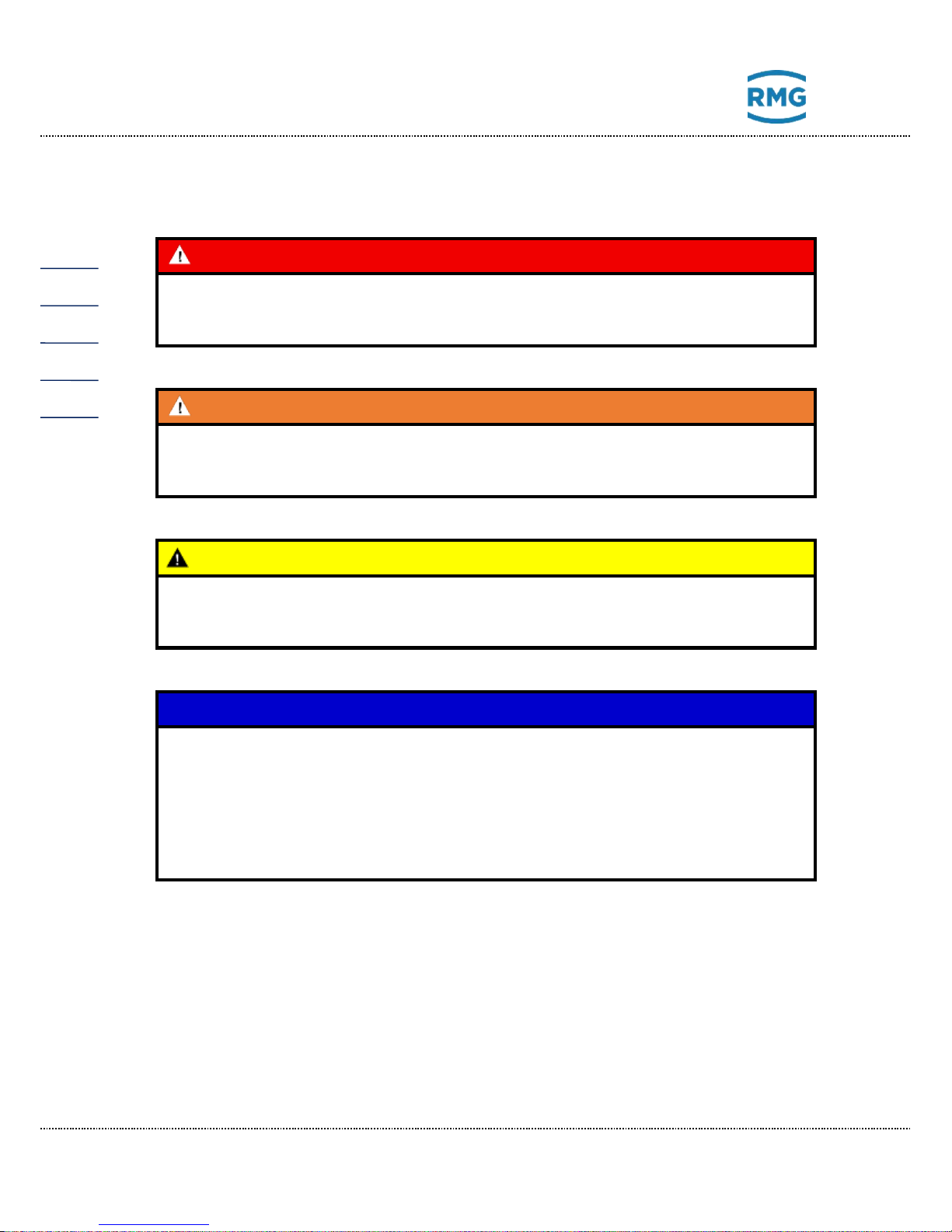
Danger
This warning notice informs you of imminently threatening dangers that can
arise due to misuse/operator error. If these situations are not avoided, death
or severe injuries can occur.
Warning
This warning notice informs you of potentially dangerous situations that can
arise due to misuse/operator error. If these situations are not avoided, minor
injuries can occur.
Caution
This notice informs you of potentially dangerous situations that can arise
due to misuse/operator error. If these situations are not avoided, damage to
the device or nearby property can occur.
Note
This notice informs you of potentially dangerous situations that can arise
due to misuse/operator error. If these situations are not avoided, damage to
the device or nearby property can occur.
This notice can provide you with helpful tips to make your work easier. This
notice also provides you with further information about the device or the
work process in order to prevent operator error.
Page 7
1 About this manual
Manual GC 9300 EN14 July, 24th 2018
3
1.1.4 Working with the device
1.1.4.1 Safety notices Danger, Warning, Caution and Note
Danger
All of the following safety notices must be observed !!
Disregard of the safety notices can result in danger to the life and limb or
environmental and property damage.
Bear in mind that the safety warnings in this manual and on the device cannot
cover all potential dangerous situations, because the interaction of various conditions can be impossible to foresee. Merely following the instructions may not suffice for correct operation. Always remain attentive and consider potential consequences.
• Read this operating manual and especially the following safety notices carefully before working with the device for the first time.
• Warnings are provided in the operating manual for unavoidable residual
risks for users, third parties, equipment or other property. The safety instructions used in this manual do not refer to unavoidable residual risks.
• Only operate the device in fault-free condition and in observance of the operating manual.
• Compliance with local statutory accident prevention, installation and assembly regulations is also mandatory.
Note
All notices in the manual must be observed.
Use of the analytical computer GC 9300 is only permitted in accordance with
the specifications in the operating manual.
RMG assumes no liability for damages arising due to disregard of the oper-
ating manual.
Page 8
1 About this manual
Manual GC 9300 EN14 July, 24th 2018
4
Danger
Service and maintenance tasks or repairs that are not described in the operating manual must not be carried out without prior consultation with the
manufacturer.
Changes to the analytical computer GC 9300 are not permitted.
The technical specifications must be observed and followed for safe opera-
tion (Chapter 6 Technical data). Performance limits must not be exceeded.
For safe operation, the analytical computer GC 9300 must only be used in
the scope of the intended use (Chapter 1.3 Function to 1.5 Area of applicabil-
ity)
The GC 9300 complies with current standards and regulations. However,
danger can arise with misuse and the measuring element of the PGC can be
destroyed due to operator error.
1.1.4.2 Dangers during commissioning
Initial commissioning
The initial commissioning must only be carried out by
specially trained personnel (training by RMG) or RMG
service personnel.
Note
An acceptance test certificate must be created during the commissioning.
This, the operating manual and the CE Declaration of Conformity must be
stored so that they are always readily available.
All sharp edges on the device were removed, insofar as possible. However,
suitable personal protective equipment provided by the operator must be
worn during all work.
Page 9
1 About this manual
Manual GC 9300 EN14 July, 24th 2018
5
Danger
This symbol is used in the manual as a warning of the danger
of explosion; observe the instructions following the symbol.
With the danger of explosion, the following must be observed,
in particular:
The analytical computer GC 9300 is not approved or designed for use in explosion-prone areas. Installation must only take place in safe rooms. The
analytical computer is intended for installation in a control cabinet in an
electronics room.
Install the device as specified in the operating manual. If the device is not
installed as specified in the operating manual, there may be a risk that other
connected devices have adequate explosion protection.
Inadequately qualified persons working on the equipment are unable to correctly estimate dangers. Explosions can be triggered. Only work on the
equipment if you have the appropriate qualifications.
Components can be damaged if you do not use suitable tools and materials.
Use tools that are recommended for the respective work in the operating
manual.
Mechanical installation
Mechanical installation must only be performed by appropriately qualified technicians.
Electrical installation
Installation on electrical components must only be carried
out by qualified electricians.
Mechanical and/or electrical installation
These qualified personnel require training specifically for
work in explosion-prone areas. Qualified personnel are
persons who have training / education in accordance with
DIN VDE 0105, IEC 364 or comparable standards.
Note
• Before connecting the voltage supply, ensure that all gas lines to the
measuring element and the measuring element itself have been flushed. If
there is still air in the line system or the measuring element, the measuring element will be destroyed. For this reason, you must also observe the
operating manual for the PGC measuring element CP 4900!
Page 10
1 About this manual
Manual GC 9300 EN14 July, 24th 2018
6
Danger
• In general, the replacement of an analytical computer GC 9300 must only
be carried out by RMG Service.
1.1.4.3 Dangers during maintenance and repair
Operating personnel
The operating personnel use and operate the device in
the scope of the intended use.
Maintenance personnel
Work on the device must only be carried out by qualified
personnel who can carry out the respective tasks on the
basis of their technical training, experience and familiarity
with the applicable standards and requirements. These
qualified personnel are familiar with the applicable statutory regulations for accident prevention and can independently recognize and avoid potential dangers.
Maintenance and cleaning
Maintenance and cleaning must only be performed by
appropriately qualified technicians.
Danger
Inadequately qualified persons working on the equipment are unable to correctly estimate dangers. Explosions can be triggered.
Danger
The device can be damaged if it is not cleaned as specified in the operating
manual. Only clean the device as specified in the operating manual.
Components can be damaged if you do not use suitable tools.
- Only clean the device with a slightly damp cloth!
Page 11
1 About this manual
Manual GC 9300 EN14 July, 24th 2018
7
1.1.4.4 Qualification of personnel
Note
In general, the following is recommended for all persons working with or on
the analytical computer GC 9300:
• Training / education for work in explosion-prone areas.
• The capacity to be able to correctly estimate dangers and risks when
working with the analytical computer GC 9300 and all connected devices.
• Training / education by RMG for work with gas measuring devices.
• Education / instruction in all national standards and directives to be com-
plied with for the work to be carried out on the GC 9300 analytical computer.
1.1.5 Risk assessment and minimization
According to assessment by qualified employees of RMG, the analytical computer
GC 9300 is subject to risks during its use. Risks can arise, for instance, during use
outside of the permissible temperature range. Impermissible current and voltage
values can trigger explosions in explosion-prone areas. Naturally, work must only
be carried out by trained personnel (see chapter 1.1.4.4 Qualification of person-
nel), who are also trained to recognize suitable tools and use them exclusively.
These risks were summarized alongside development and measures were taken
to minimize these risks.
Measures for risk minimization:
- The maximum permissible temperature range is specified on the type plate
of the analytical computer GC 9300. Operation of the device is only permitted within these specified ranges.
Page 12
1 About this manual
Manual GC 9300 EN14 July, 24th 2018
8
Danger
- The wiring from and installation of the analytical computer GC 9300 in
explosion-prone areas must only be carried out by trained personnel
in accordance with EN60079-14 and in observance of national regulations.
- Qualified persons must satisfy the definitions in accordance with DIN
EN 0105 or IEC 364 or directly comparable standards.
- Only trained and instructed personnel are permitted. Work on the
measuring system must only be carried out from qualified persons
and inspected by responsible qualified supervisors.
- Qualified persons have been authorized by the person responsible for
safety of personnel to carrying out such work on the basis of their
training, experience or instruction and familiarity with applicable
standards, provisions, accident prevention regulations and system
conditions. It is essential that these persons are able to recognize and
avoid potential dangers in good time.
1.1.6 Applicability of the manual
This manual describes the analytical computer GC 9300. The analytical computer
GC 9300 is only part of a complete system. The manuals of the other components
of the system must be observed. If you find contradictory instructions, contact
RMG and/or the manufacturers of the other components.
Note
Ensure that the power data of the current connection matches the specifications on the type plate. Observe any applicable national regulations in the
country of use. Use cable that is appropriate for the cable fittings.
Danger
Only work on the equipment if you have the appropriate training and qualifications.
1.1.6.1 Danger during operation
Observe the specifications of the system manufacturer and/or system operator.
Page 13
1 About this manual
Manual GC 9300 EN14 July, 24th 2018
9
1.1.6.2 Dangers of operation in EX areas
The analytical computer GC 9300 is not intended for use in explosion-prone areas.
Only operate the analytical computer GC 9300 in fault-free and complete condi-
tion.
If you make technical changes to the device, safe operation can no longer be
guaranteed.
Danger
• Only use the analytical computer GC 9300 in its original condition.
• When connecting the measuring element, an external oxygen sensor or
additional equipment in explosion-prone areas, ensure that the appropriate explosion protection is provided for these components.
• They are intrinsically safe devices for which galvanic isolation must be
provided with connection of these devices.
1.1.6.3 Responsibility of the operator
As the operator, you must ensure that only adequately qualified personnel work on
the device. Ensure that all employees who work with the device have read and
understood this manual. You are also obligated to train personnel regularly and
inform them of the dangers. Ensure that all work on the device is carried out exclusively by qualified persons and inspected by responsible qualified supervisors.
The responsibilities for installation, operation, fault rectification, maintenance and
cleaning must be clearly regulated. Instruct your personnel with regard to the risks
involved with working with the device.
1.1.7 Transport
The device is packaged specific to the transport requirements for each customer.
Ensure safe packaging that absorbs light impact and vibrations is used for any
further transport. Nevertheless, inform the transport company that all types of impact and vibrations should be avoided during transport.
Page 14
1 About this manual
Manual GC 9300 EN14 July, 24th 2018
10
1.1.8 Scope of delivery
The scope of delivery can differ depending on the optional orders. The following is
“normally” included in the scope of delivery:
Part
Quantity
Analytical computer GC 9300
1
Optional:
Gateway GC 9310
1
Manual
1 … …
1.1.9 Disposal of packaging material
Dispose of the material in an environmentally friendly manner in accordance with
national standards and directives.
1.1.10 Storage
Avoid extended periods of storage. Inspect the analytical computer GC 9300 for
damage and correct function after storage. Contact the RMG service department
to arrange for inspection of the device after a storage period of longer than one
year. For this purpose, send the device to RMG.
Page 15

1 About this manual
Manual GC 9300 EN14 July, 24th 2018
11
1.2 Structure of the manual
The introduction of this manual comprises two parts. The first part lists general
specifications; the symbols used in the manual and the structure of notices are
presented and a risk assessment is provided. It also includes specifications for
transport and storage of the analytical computer GC 9300. The second part describes how the GC 9300 works and its intended purpose.
The second chapter explains the basic function and operation of the GC 9300 and
data storage – taking place in accordance with the DSFG standard, in particular.
The electrical connections, inputs, outputs and interfaces are explained in the third
section.
The fourth chapter describes the commissioning and how the GC 9300 is connected to a PC. It also explains that the number of DSFG interfaces can be increased using a gateway – the GC 9310. The fifth chapter covers the operation of
the GC 9300 and explains the individual menus in detail.
Chapter six summarizes the technical specifications. The Appendix provides an
extensive list of parameters and some additional details about the GC 9310.
Page 16

1 About this manual
Manual GC 9300 EN14 July, 24th 2018
12
1.3 Function
The analytical computer GC 9300 is a component of the process gas chromatograph PGC 9300, which analyzes natural gas and biogas and provides the necessary measurement values to determine the energy content and calculate the compressionability factor. As a control computer, it determines the progress of the
analysis and delivers measurement results. It stores all operating parameters and
is also used for operation.
In addition to analysis control, the GC 9300 provides the following functions:
• Calculation of calorific value, heat value, standard density, and Wobbe index from the percentages of individual gas components in accordance with
ISO 6976, and the optional calculation of the methane number.
• Storage of analysis results in archives.
• Comprehensive communication functions.
• Operating mode settings for inspection purposes and analysis of gas sam-
ples.
1.4 Mode of operation
The analytical computer GC 9300 is the controller for the process gas chromatograph PGC 9300 and controls the analysis process in the measuring element CP
4900. In normal operation, an analysis begins as soon as the preceding analysis is
finished, wherein each analysis lasts about 3-4 minutes, depending on the variant.
The series of analyses proceeds without interruption by automatic calibrations. A
calibration, whether it takes place automatically or is started manually, 4 or 5 calibrating gas analyses and takes between 12 and 16 minutes depending on the device type. The calibration interval of 1 day is specified in the PTB approval.
A calibration can also be started manually at any time.
The PGC 9300 can be designed as a single stream unit for analysis of the gas
from one extraction point or as a multi-stream unit for up to 4 extraction points.
With multi-stream units, the measured gases changes with each analysis in the
standard setting.
The basis of an analysis is the signal curve of the sensor for each column unit,
which is called a chromatogram. Each peak in this chromatogram marks a gas
component. In the evaluation, the area under the peaks are determined, from
which polynomials are derived to calculate the proportion of gas components in
Page 17

1 About this manual
Manual GC 9300 EN14 July, 24th 2018
13
mol%. The polynomial coefficients are determined in the factory calibration in
which a correction factor (response factor) is calculated for each component in
the automatic and manual calibration.
A basic calibration is carried out during commissioning and after various repair
and service tasks. The response factors derived from this do not change during
running operation and serve for comparison with the current response factors used
for the evaluation. As a result, it can enable recognition of a drift of the measuring
element due to an enrichment of moisture or heavy carbon dioxide. If the deviation
is greater than 10%, an alarm message appears and the column modules must be
heated to gas out. Basic calibration is not permitted during running operation.
In addition to the custody transfer parameters calorific value and standard density,
which were already mentioned, the analytical computer calculates the heating value, density ratio and Wobbe index, and, optionally, the methane number as a noncustody-transfer factors from the individual components. The calculation takes
place in accordance with ISO 6976 (except for the methane number).
1.5 Area of applicability
The analytical computer GC 9300 is an essential element of the overall measuring
unit, which analyzes natural gas and biogas and provides the necessary measurement values to determine the energy content and calculate the compression
ability factor. The analytical computer GC 9300 is the controller, or control computer, for the process gas chromatograph PGC 9300 and controls the analysis
process in the measuring element CP 4900. It stores all operating parameters and
is also used for operation. It records and calculates the measurements, enables
display of the measurement results and calculation factors and stores and transmits this data.
The PGC9300_ME_manual_en_06 (and the English manual) describes the different types that are used in different areas. The PGC 9301 is designed for use in
"normal" natural gas. It works with 2 column modules. The PGC 9302 is designed
for use in biogas. It works with 2 column modules (A and C). The PGC 9303 allows the determination of further gas components in "normal" natural gas. It works
with 3 column modules (A, B and C). The PGC 9304 allows the determination of
further gas components in "normal" natural gas. It works with 3 column modules
(A, B and C), whereby argon is used as carrier gas in column C. The PGC 9305
complies with the PGC 9301. For this PGC there will be a separate approval according to Russian regulations, the GOST. The differences are described in more
detail in the Russian manual.
The permissible environmental temperatures, current and voltage values for safe
operation are specified in chapter 6 Technical data.
Page 18
2 Introduction
Manual GC 9300 EN14 July, 24th 2018
14
2 Introduction
2.1 Touch screen
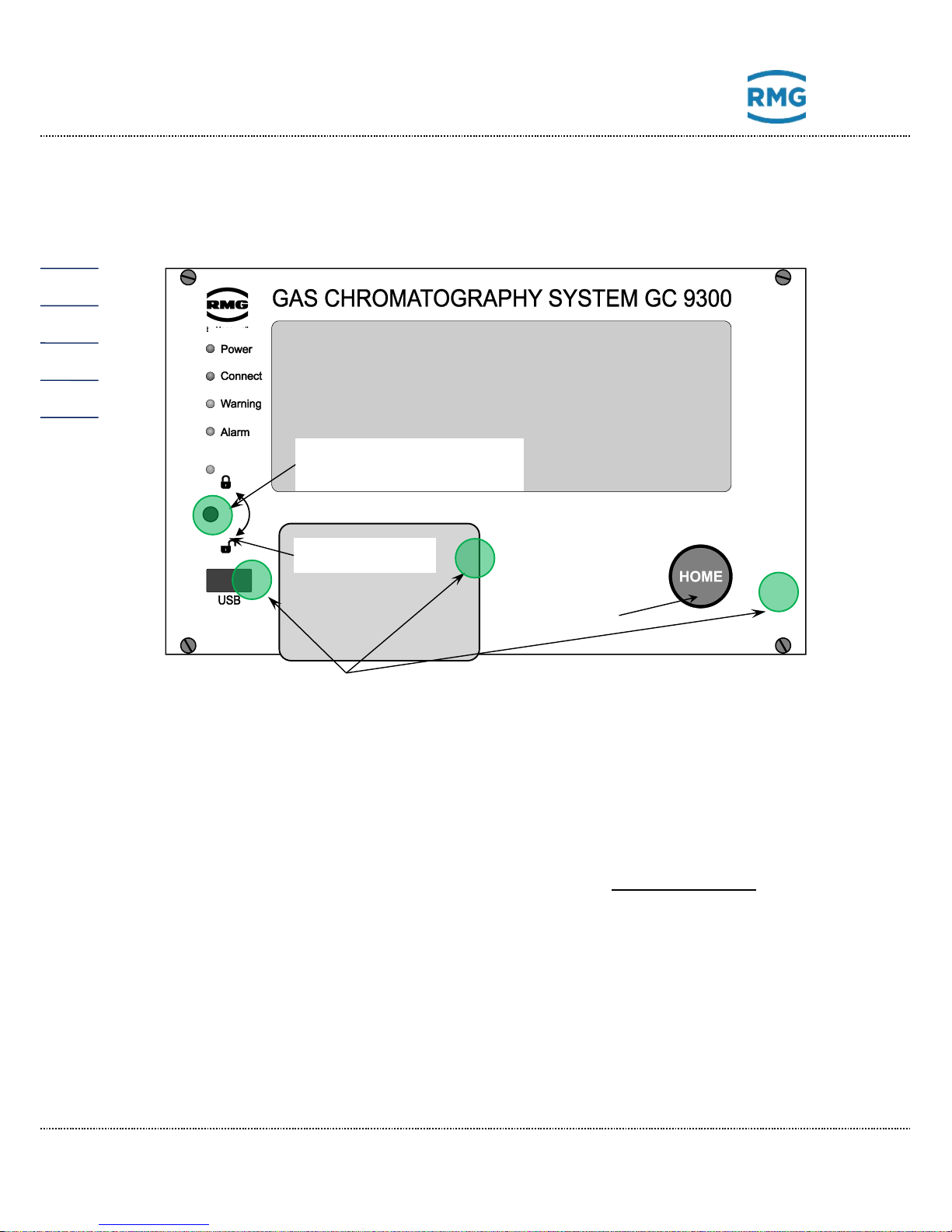
The following display and operating elements are located on the front panel:
Green LED
(Power)
Continuously illuminated: Voltage indicator.
Blinking light: Open custody transfer switch and/or open user lock.
Orange LED
(Connect)
Continuously illuminated: The measuring element is connected and
active.
Yellow LED
(Warning)
Continuously illuminated: A warning has been issued
Blinking light: Warning: Current fault of non-custody-transfer function(s)
Red LED
(Alarm)
Continuously illuminated: An alarm has been issued
Blinking light: Alarm: Current fault of custody transfer function(s)
Custody transfer
switch
Sealable rotary switch; the custody transfer lock is opened at the mechanical limit stop (in clockwise direction).
USB interface
For connection of USB components (e.g. a mouse), sealed in custody
transfer mode.
HOME button
To switch between the start screen and error screen.
Touch screen
Display and control panel of the analytical computer.
Touch screen
Home button
Custody transfer switch
as a rotary switch
Type plate
Sealing
Safety marks
Page 19
2 Introduction
Manual GC 9300 EN14 July, 24th 2018
15
Operation via the touch screen is possible with an easy to understand menu. A PC
connected via the network interface enables the following types of operation:
1. Operating software RMGViewGC.
2. Any internet browser for viewing and storing of non-custody-transfer archives.
Further operating possibilities are available via DSfG bus with RMG software
products such as the PGC revision program AKA-II.
2.2 Operation
Operation takes place on the analytical computer GC 9300 and enables the following actions:
• Reading of analysis results
• Starting of a manual calibration
• Switchover of the analysis from measuring gas to testing gas (reference
gas)
• Displaying and changing operating parameters
• Viewing of archives and log books
• Display of chromatograms
• Display of error messages
• Display of the device status
Note
Entry of the code number and/or opening of the custody transfer switch is
necessary for nearly all actions other than the display functions.
2.2.1 Operating modes
The following operating modes are available for the PGC 9300 in the “Details”
screen under “GC 9300 mode”:
• AUTORUN Normal analysis mode with automatic calibrations
• STOP Analysis mode is stopped
• BASIC CALIB. Basic calibration
(protected against inadvertent triggering)
Page 20

2 Introduction
Manual GC 9300 EN14 July, 24th 2018
16
• NORMAL CALIB. Manually started calibration
(equivalent to automatic cal.)
• REF GAS Test gas analysis (reference gas)
Page 21
2 Introduction
Manual GC 9300 EN14 July, 24th 2018
17
2.3 Data storage
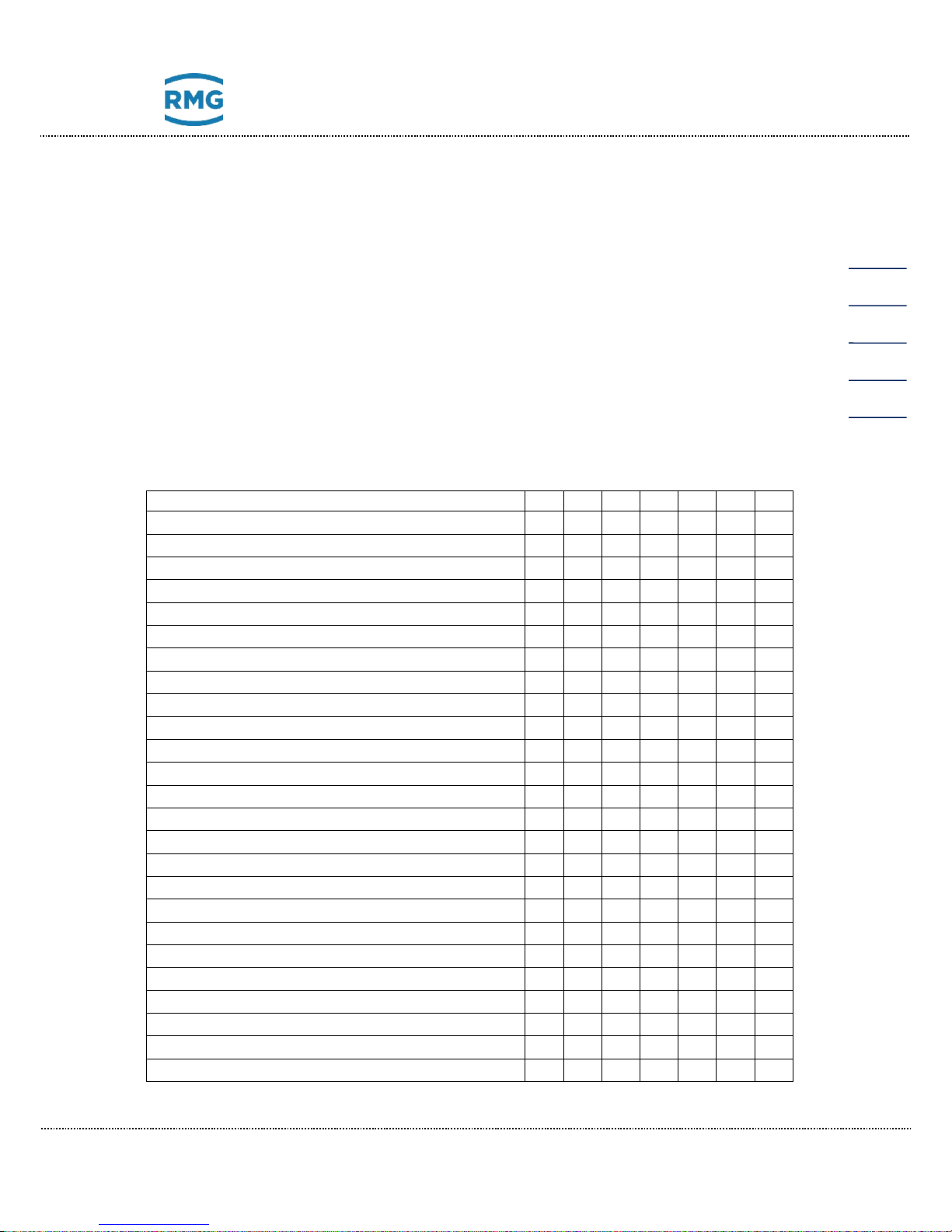
There are two archives available for storage of analysis results - a non-custodytransfer measurement archive and a custody transfer archive according to the
DSfG standard. The structure and memory capacity of the two archives are as follows:
Measurement archive
Event log book 1,000 entries
Parameter log book 1,000 entries
Individual analysis archive 351,360 entries
Hourly averages archive 17,568 entries
Daily averages archive 186 entries
Monthly averages archive 120 entries
Calibration results archive 14,640 entries
Date, time
Event (text)
Parameter – old value
Parameter – new value
Number of analyses per entry
Number of valid analyses
Stream, gas type
Calorific value
Wobbe index
Standard density
Density ratio
Calorific value
Real gas factor
Methane number
Unnormalized total
Molar content of individual components (20)
User values (20)
Peak area (20)
Retention times (20)
Retention times with the basic calibration
Response factors (20)
Response factors with the basic calibration (20)
Peak start time (20)
Peak end time (20)
Total area
Page 22
2 Introduction
Manual GC 9300 EN14 July, 24th 2018
18
2.3.1 Archive according to the DSfG standard
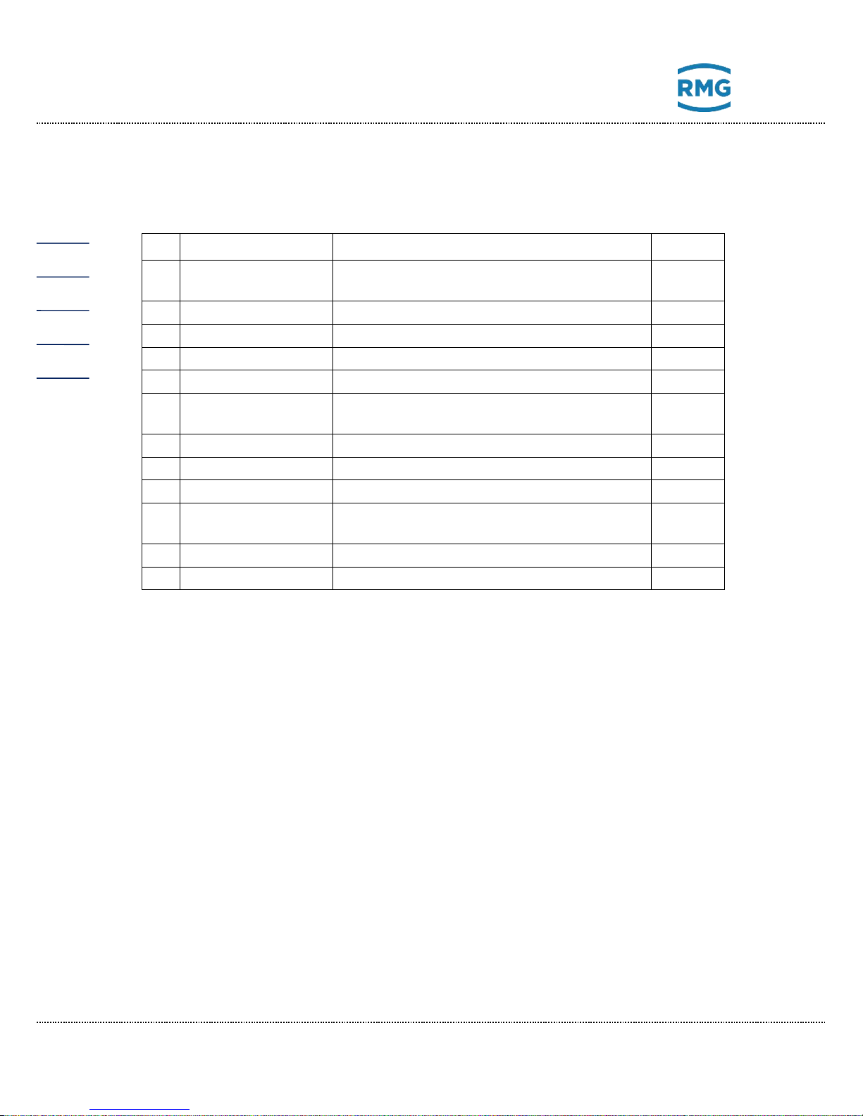
The DSfG archive is divided into archive groups 1 to 23:
AG
Description
Contents
Entries
1
Hourly averages 1
Ho, rhon, Dv, N2, CO2, H2, Hu, Wo, Wu,
MZ, Zn, bit string
2280
3
Measurements
Ho, rhon, components, bit string
960
5
Hourly averages 2
Ho, rhon, components, bit string
2280
7
Daily averages
Ho, rhon, components, bit string
95
9
Monthly average
Ho, rhon, components, bit string
24
11
Calibration gas
Calibration results: ΔHo, Δrhon, ΔCO
2,
RFs, cal. status
200
13
Reference gas
Ho, rhon, components, bit string, Hu
700
15
Long-term archive
Ho, rhon, CO2, bit string
70848
17
Analog averages
Analog values 1 to 16, status bit string
2280
19
Extended
Hourly averages
Hu, Wo, Wu, MZ, Zn,
unnormalized total components
2280
21
Reference gas
Ho, rhon, CO2, bit string
700
23
Log book
Event, Ho, rhon, components
2280
Page 23
3 Installation
Manual GC 9300 EN14 July, 24th 2018
19
3 Installation
3.1 Installation
The analytical computer GC 9300 is intended for installation in a control cabinet in
a non-Ex area. Installation takes place in a dedicated rack; the device dimensions
are:
W x H x D = 213 x 128.4 x 310 mm (42 TE / 3 HE)
Danger
The GC 9300 is not intended for use in explosion-prone areas.
Installation must only take place in safe rooms!!
3.2 Electrical connections
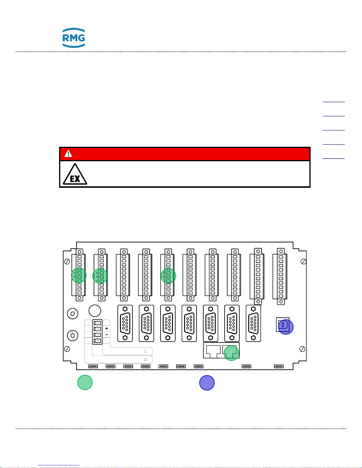
The following figure shows the rear wall of the GC 9300.
The connections are made on the rear wall. If the number of inputs/outputs is not
adequate, an additional module (Wago) with additional digital and analog inputs
24VDC F1=2A
100-230VAC F1=1,6A
Ethernet
PE PE
N
L
X19
RMG
X18
X39
USB-D
X16
WA-
WA+
A8-
A8+
A7-
A7+
A6-
A6+
A5-
A5+
5
10
9
8
7
6
4
3
2
1
X2
AL-
AL+
A4-
A4+
A3-
A3+
A2-
A2+
A1-
A1+
5
10
9
8
7
6
4
3
2
1
X1
E11-
E11+
A12-
A12+
A11-
A11+
A10-
A10+
A9-
A9+
5
10
9
8
7
6
4
3
2
1
X3
t1-
t1s
t1s
t1+
I3e
I3e
I2e
I2e
I1e
I1e
5
10
9
8
7
6
4
3
2
1
X5
I8e
I8e
I7e
I7e
I6e
I6e
I5e
I5e
I4e
I4e
5
10
9
8
7
6
4
3
2
1
X6
E5-
E5+
E4-
E4+
E3-
E3+
E2-
E2+
E1-
E1+
5
10
9
8
7
6
4
3
2
1
X7
E10-
E10+
E9-
E9+
E8-
E8+
E7-
E7+
E6-
E6+
5
10
9
8
7
6
4
3
2
1
X8
E12-
E12+
S4-
S4+
S3-
S3+
S2-
S2+
S1-
S1+
5
10
9
8
7
6
4
3
2
1
X4
X11
COM1
X12
COM2
X13
COM3
X14
COM4
COM5
X15
COM6
X37 X38
COM7
F1
Nr. 2 Nr. 1
5
10
9
8
7
6
4
3
2
1
X9
E17-
E17+
E16-
E16+
E15-
E15+
E14-
E14+
E13-
E13+
X10
5
10
9
8
7
6
4
3
2
1
E20-
E20+
E19-
E19+
E18-
E18+
Secured connection
Safety mark
(interface blocked)
Page 24
3 Installation
Manual GC 9300 EN14 July, 24th 2018
20
and outputs can be connected via an RS 232 interface. The corresponding parameters are displayed in the Details screen under “External I/O system”.
Note
The Wago module can be parameterized without a code word or custody
transfer lock.
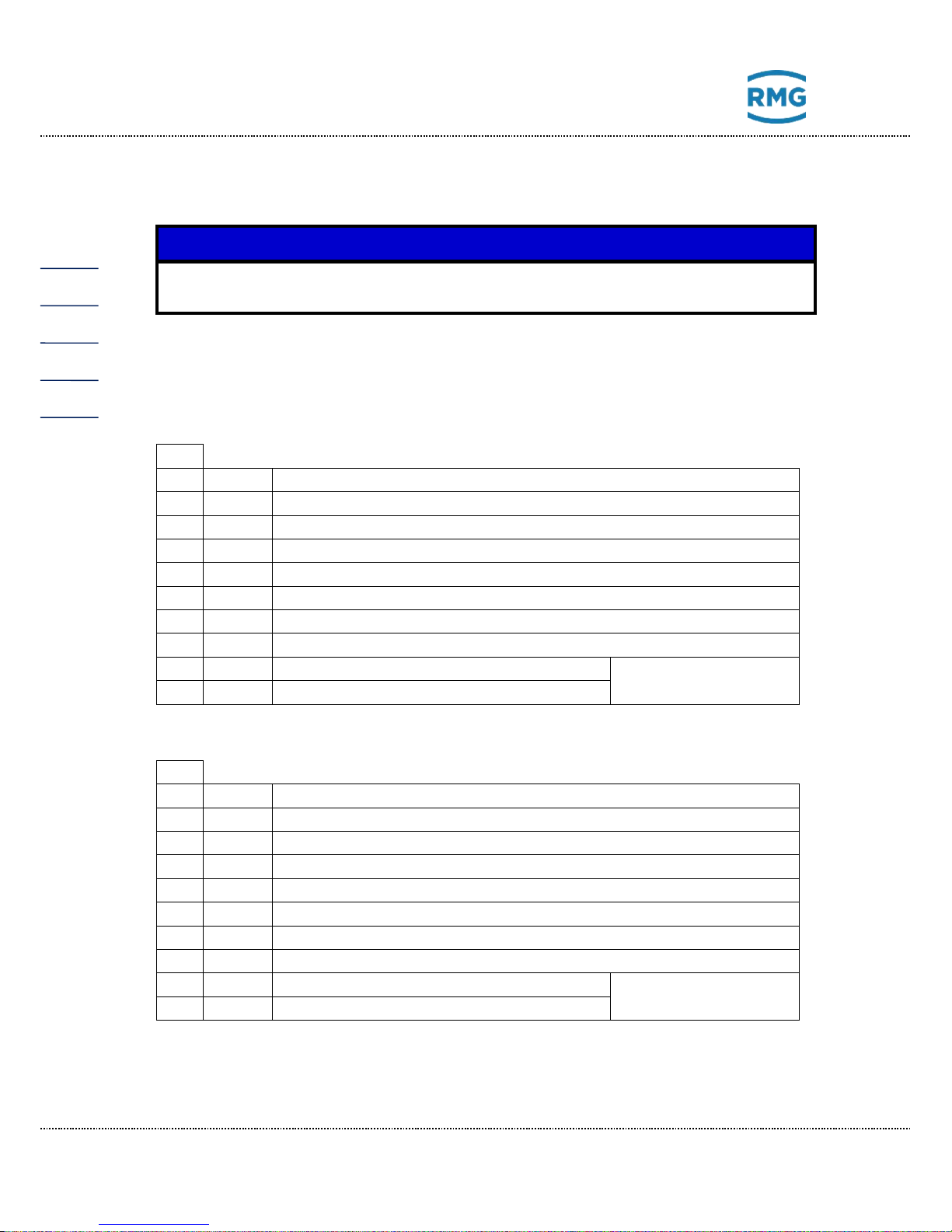
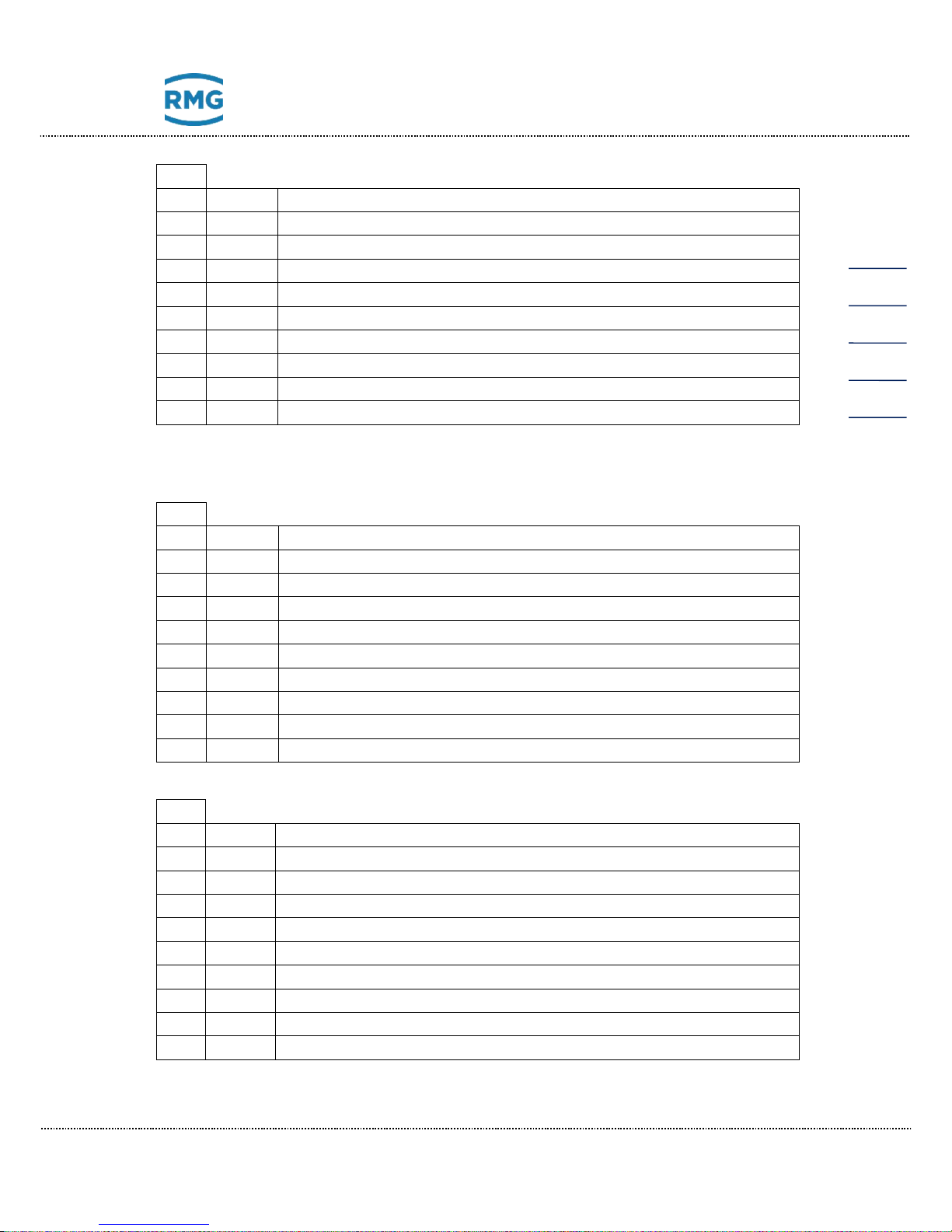
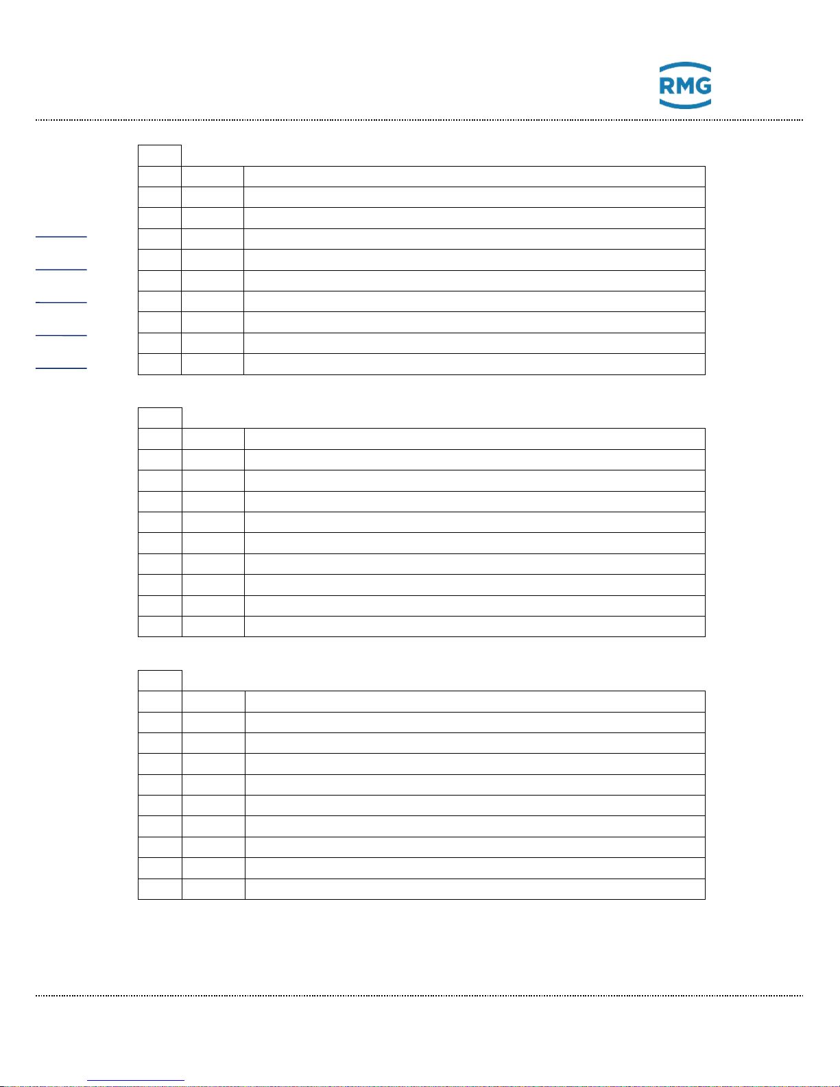
3.2.1 Connection assignment
Pin assignment
X1 1 A1+
Digital output 1 + PGC: Valve stream 1 +
2
A1-
Digital output 1 - PGC: Valve stream 1 -
3
A2+
Digital output 2 + PGC: Valve stream 2 +
4
A2-
Digital output 2 - PGC: Valve stream 2 -
5
A3+
Digital output 3 + PGC: Valve stream 3 +
6
A3-
Digital output 3 - PGC: Valve stream 3 -
7
A4+
Digital output 4 + PGC: Valve stream 4 +
8
A4-
Digital output 4 - PGC: Valve stream 4 -
9
AL+
Alarm contact + PGC: Alarm +
Contact open in the
event of an alarm
10
AL-
Alarm contact - PGC: Alarm -
X2 1 A5+
Digital output 5 + Calibration gas valve
2
A5-
Digital output 5 - Calibration gas valve
3
A6+
Digital output 6 + Reference gas valve
4
A6-
Digital output 6 - Reference gas valve
5
A7+
Digital output 7 + Calibration running
6
A7-
Digital output 7 - Calibration running
7
A8+
Digital output 8 + Collective message for digital outputs 9 - 12
8
A8-
Digital output 8 - Collective message for digital outputs 9 - 12
9
WA+
Warning contact + PGC: Warning
Contact open in the
event of a warning
10
WA-
Warning contact - PGC: Warning
Page 25
3 Installation
Manual GC 9300 EN14 July, 24th 2018
21
X3
1
A9+
Digital output 9 + Limit value exceeded analog value 1*
2
A9-
Digital output 9 - Limit value exceeded analog value 1*
3
A10+
Digital output 10 + Limit value exceeded analog value 2*
4
A10-
Digital output 10 - Limit value exceeded analog value 2*
5
A11+
Digital output 11 + Limit value exceeded analog value 3*
6
A11-
Digital output 11 - Limit value exceeded analog value 3*
7
A12+
Digital output 12 + Limit value exceeded analog value 4*
8
A12-
Digital output 12 - Limit value exceeded analog value 4*
9
E11+
Input 11 + (Note: passive input, U
max
= 30 V)
10
E11-
Input 11 – (Note: passive input, U
max
= 30 V)
* The analog values under "Specialties“ can be monitored for limit values. Exceeding these limits
leads to a warning or the setting of a signaling contact.
X4 1 S1+
Current output 1 +
2
S1-
Current output 1 -
3
S2+
Current output 2 +
4
S2-
Current output 2 -
5
S3+
Current output 3 +
6
S3-
Current output 3 -
7
S4+
Current output 4 +
8
S4-
Current output 4 -
9
E12+
Input 12 + (Note: passive input, U
max
= 30 V)
10
E12-
Input 12 – (Note: passive input, U
max
= 30 V)
X5 Polarity of current inputs depends on operating mode (active/passive).
1
I1e
Current input 1 Carrier gas pressure – I (He)
2
I1e
Current input 1 Carrier gas pressure – I (He)
3
I2e
Current input 2 Measuring gas pressure
4
I2e
Current input 2 Measuring gas pressure
5
I3e
Current input 3 (active - / passive +)
6
I3e
Current input 3 (active + / passive -)
7
t1+
Temperature input 1 supply ++ Room temperature
8
t1s
Temperature input 1 sense + Room temperature
9
t1s
Temperature input 1 sense - Room temperature
10
t1-
Temperature input 1 supply -- Room temperature
Page 26
3 Installation
Manual GC 9300 EN14 July, 24th 2018
22
X6 Polarity of current inputs depends on operating mode (active/passive).
1
I4e
Current input 4 (active - / passive +)
2
I4e
Current input 4 (active + / passive -)
3
I5e
Current input 5 Carrier gas pressure – II (argon)
4
I5e
Current input 5 Carrier gas pressure – II (argon)
5
I6e
Current input 6 (active - / passive +)
6
I6e
Current input 6 (active + / passive -)
7
I7e
Current input 7 / Temperature input 2 supply ++
8
I7e
Current input 7 / Temperature input 2 sense +
9
I8e
Current input 8 / Temperature input 2 sense -
10
I8e
Current input 8 / Temperature input 2 supply --
X7
1
E1+
Digital input 1 + P
min
helium - 1
2
E1-
Digital input 1 - P
min
helium - 1
3
E2+
Digital input 2 + P
min
helium - 2
4
E2-
Digital input 2 - P
min
helium - 2
5
E3+
Digital input 3 + P
min
calibration gas
6
E3-
Digital input 3 - P
min
calibration gas
7
E4+
Digital input 4 + P
min
test gas
8
E4-
Digital input 4 - P
min
test gas
9
E5+
Digital input 5 + T
min
calibration gas
10
E5-
Digital input 5 - T
min
calibration gas
X8 1 E6+
Digital input 6 + T
min
test gas
2
E6-
Digital input 6 - T
min
test gas
3
E7+
Digital input 7 + P
max
high-pressure reduction stream - 1
4
E7-
Digital input 7 - P
max
high-pressure reduction stream - 1
5
E8+
Digital input 8 + P
max
high-pressure reduction stream - 2
6
E8-
Digital input 8 - P
max
high-pressure reduction stream - 2
7
E9+
Digital input 9 + P
max
high-pressure reduction stream - 3
8
E9-
Digital input 9 - P
max
high-pressure reduction stream - 3
9
E10+
Digital input 10 + P
max
high-pressure reduction stream - 4
10
E10-
Digital input 10 - P
max
high-pressure reduction stream - 4
Page 27
3 Installation
Manual GC 9300 EN14 July, 24th 2018
23
X9
1
E13+
Digital input 13 + Valve control stream – 1
2
E13-
Digital input 13 - Valve control stream – 1
3
E14+
Digital input 14 + Valve control stream – 2
4
E14-
Digital input 14 - Valve control stream – 2
5
E15+
Digital input 15 + Valve control stream – 3
6
E15-
Digital input 15 - Valve control stream – 3
7
E16+
Digital input 16 + Valve control stream – 4
8
E16-
Digital input 16 - Valve control stream – 4
9
E17+
Digital input 17 + Alarm input
10
E17-
Digital input 17 - Alarm input
X10
1
E13+
Digital input 18 + P
min
argon - 1
2
E13-
Digital input 18 - P
min
argon – 1
3
E14+
Digital input 19 + P
min
argon – 2
4
E14-
Digital input 19 - P
min
argon – 2
5
E15+
Digital input 20 + Warning input
6
E15-
Digital input 20 - Warning input
7 Not allocated
8 Not allocated
9 Not allocated
10 Not allocated
3.2.2 Power supply
X16
230 V/AC version
24 V/DC version
L 100 – 230 V
Not allocated
Not allocated
+
+ 24 V
N 100 – 230 V
-
- 24 V
PE
Potential equalization
PE
Potential equalization
Page 28
3 Installation
Manual GC 9300 EN14 July, 24th 2018
24
3.2.3 Interfaces
Network interfaces
X18:
Ethernet interface 1
For connection with the measuring element CP 4900
X19:
Ethernet interface 2
For connection of a PC or to a local network
Serial interfaces
X11:
COM 1
RS 232 / RS 485*
Modbus RTU / Modbus ASCII
X12:
COM 2
RS 232
WAGO-IO / GPS 170
X13:
COM 3
RS 232 / RS 485*
DSfG / Modbus RTU / Modbus ASCII / RMG-Bus
X14:
COM 4
RS 232 / RS 485*
DSfG / RMG-Bus
X15:
COM 5
RS 232
Modbus RTU / Modbus ASCII
X37:
COM 6
RS 232 / RS 485*
Modbus RTU / Modbus ASCII / RMG-Bus
X38:
COM 7
RS 232 / RS 485*
Modbus RTU / Modbus ASCII
* configurable in the device with jumpers, delivery state in bold text.
3.2.4 Additional external In- and Outputs
The GC9300 and GC9310 (Gateway) have a maximum of in- and outputs:
• 8 analog inputs
• 4 Analog outputs
• 20 Digital inputs
• 12 Digital outputs
If required, this limitation can be simply extended including external Wago modules:
• Up to 16 additional analog inputs
• Up to 16 additional analog outputs
• Up to 16 additional digital inputs
• Up to 16 additional digital outputs
Note
The extension of the number of external interfaces is also possible for the
Gateway GC 9310.
Page 29
3 Installation
Manual GC 9300 EN14 July, 24th 2018
25
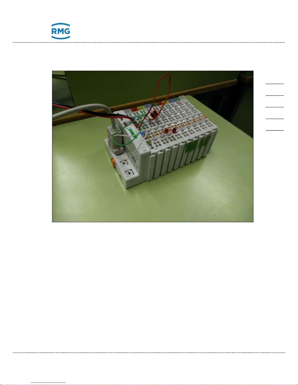
The next figure shows such a setup:
The connection module, the fieldbus coupler as Wago 750-314 or Wago 750-316,
as well as the end module, the bus terminal Wago 750-600 are fixed. Between the
connection module and the end module you may choose the modules:
• 750-402 4-channel digital inputs
• 750-455 4-channel analog inputs
• 750-504 4-channel digital outputs
• 750-554 2-channel analog outputs
• 750-555 4-channel analog outputs
• 750-602 24 V DC power supply (galvanically isolated potential feed)
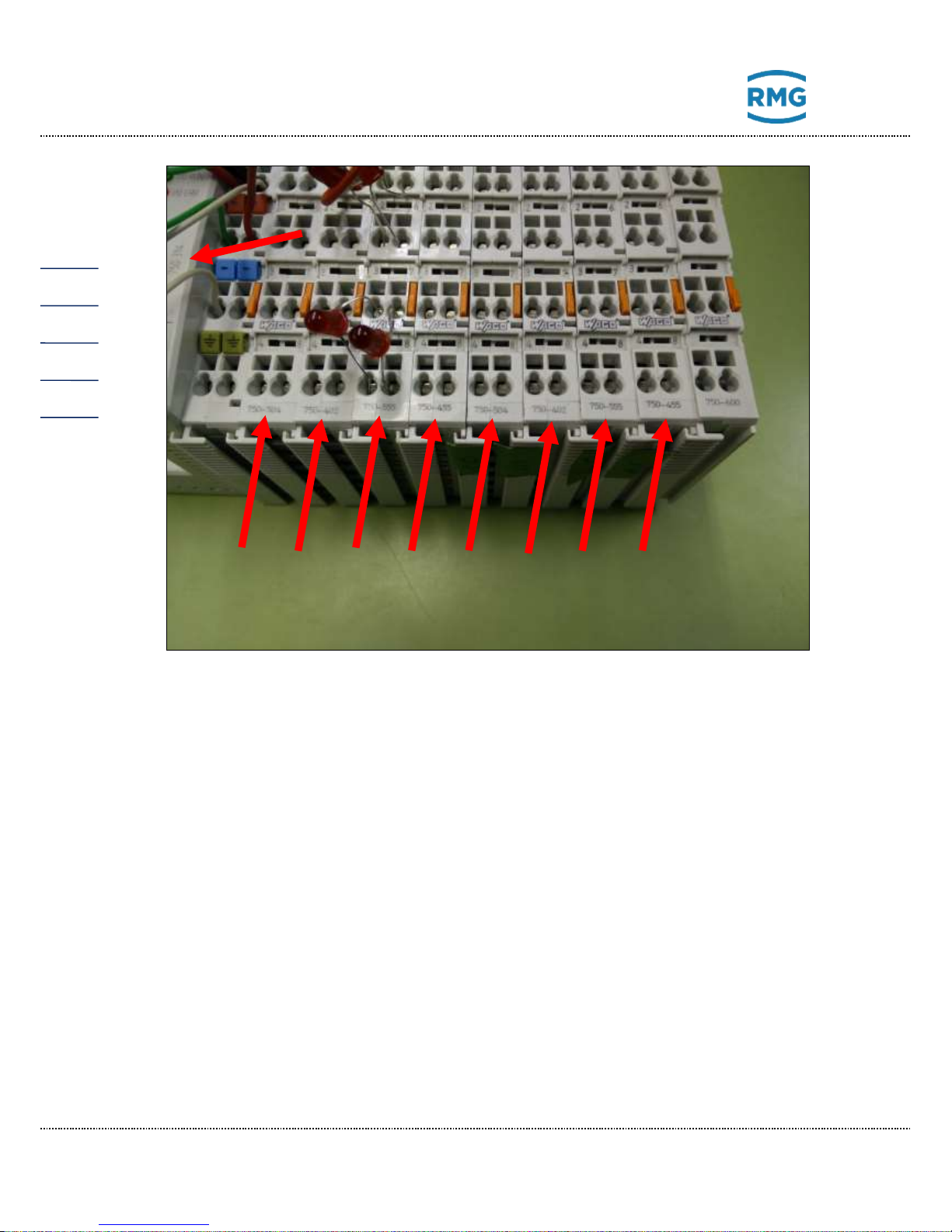
The next figure shows the above setup in an enlargement of the previous setup;
the numbers of the Wago modules can be read.
Page 30
3 Installation
Manual GC 9300 EN14 July, 24th 2018
26
With the above modules, the following inputs and outputs can be realized, for example:
• 16 digital inputs 4 x 750-402 4-channel digital inputs
• 16 analog inputs 4 x 750-455 4-channel analog inputs
• 16 digital outputs 4 x 750-504 4-channel digital outputs
• 16 analog outputs 8 x 750-554 2-channel analog outputs or the
4 x 750-555 4-channel analog outputs *1
_______________________________________________________________
*1 or any number of both modules with up to 16 analog outputs.
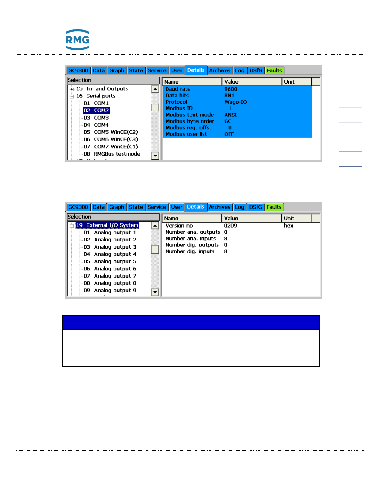
The extension of the inputs and outputs can be implemented via a serial ports of
the Wago modules to the 02 COM 2 interface of the GC9300 family. To use the
Wago modules, the following parameters on the GC93XX have to be set in the
menu item 16 serial ports, 02 COM 2 as shown in the next figure.
Page 31
3 Installation
Manual GC 9300 EN14 July, 24th 2018
27
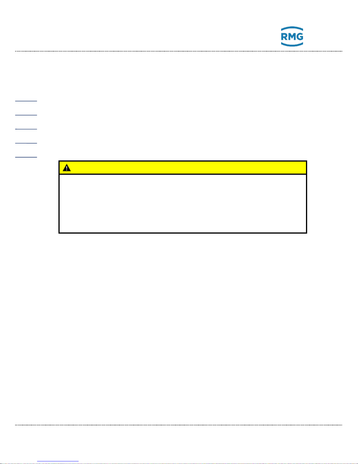
In menu item 19 External I/O System (see next figure) you may read the additional available number of additional in- and outputs. In addition, the settings and
status of the individual inputs and outputs can be parameterized and read here.
Note
he sequence of the digital inputs has been adapted to firmware version
2.003 and higher. It may therefore no longer match that of existing installations. Therefore, firmware updates should be avoided or should be realized from the RMG's service.
Page 32
4 Commissioning
Manual GC 9300 EN14 July, 24th 2018
28
4 Commissioning
4.1.1 Establishing connection to the PC
A crossover network cable is necessary for direct connection between the analytical computer and a PC; a standard network cable is required for connection to a
hub.
4.1.2 Switching on the device
Caution
• Before connecting the voltage supply for the measuring element, en-
sure that all gas lines to the measuring element and the measuring element itself have been flushed!!
• If there is still air in the supply lines or the measuring element, the
column modules can be destroyed.
• Proceed as described in the manual for the measuring element CP
4900 for ventilation.
Before switching on, please check whether the correct carrier gas pressure is set
to 5.5 bar ± 10 % in the status field. This adjustment is made via an external regulator on the bottle rack.
If this initial calibration is not successful, a second calibration must be performed
immediately thereafter. If this calibration is also unsuccessful, operation is stopped
automatically.
4.2 Gateway GC 9310
As a control computer, the GC 9300 determines the progression of the analyses of
the process gas chromatograph PGC 9300 and delivers measurement results.
Operation takes place via the analytical computer GC 9300, where all operating
parameters are stored. The gateway GC 9310 is optional and designed to extend
the 2 DSFG interfaces of the GC 9300 to 4 DSFG interfaces (GC 9300 + GC
9310); if more than two additional DSfG buses are required, additional GC 9310
units can be connected. In this case, please contact the RMG service department.
Page 33
4 Commissioning
Manual GC 9300 EN14 July, 24th 2018
29
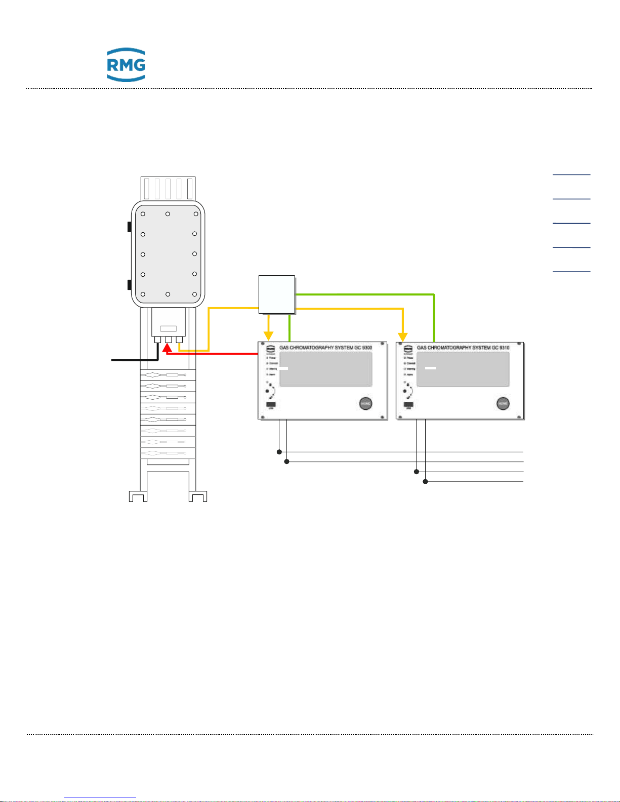
The GC 9310 delivers the same measurement results as the GC 9300. Although
the GC 9300 transmits the operating parameters to the GC 9310, the GC 9310
does not assume any tasks for control of the measuring element. The figure below
shows the configuration.
24 V DC
Valve control
and opertion
Raw data
Switch
Mesurement
element
PGC930X
DSFG-Bus 1
DSFG-Bus 2
DSFG-Bus 3
DSFG-Bus 4
GC 9300Controller
GC 9310Gateway
Parameters of the device
& Synchronisation
Like the GC 9300, the operation, display and storage of data take place via touch
screen, an internet browser or the operating software RMGViewGC.
Configuring GC 9300 for operation with GC 9310
In order to ensure that the GC 9300 Controller can work in combination with one or
several GC 9310 gateways, the following settings must be made:
• LAN-1 must be set in chapter 3.2 Electrical connections.
• The gateways are connected via a hub to LAN-1 of the GC 9300.
• Then the menu entry “LAN-1” must be selected under Details “Network ser-
vice” for the menu “DSfG extension”.
• “Send params to GW” must be selected, then the parameters from the GC
9300 are transmitted to the GC 9310.
Page 34
4 Commissioning
Manual GC 9300 EN14 July, 24th 2018
30
4.2.1 GC 9310 commissioning
• The GC 9300 controller is started up and completely configured (as described above)
• The GC 9300 is set to STOP
• The GC 9310 gateway is started up and configured (as described above)
• The GC log status LED on the start screen of the GC 9310 is now illuminat-
ed green
• Operating parameters of the GC 9300 are transmitted to the GC 9310
• The received parameters can be checked on the start screen of the GC
9310
Note
• In order for the GC 9310 to calculate in the same manner as the GC
9300, a manual calibration must be carried out!!
• This calibration is necessary because the GC 9310 performs calcula-
tions automatically!!
• When the GC 9300 continues running in AUTORUN, the two devices
run in synchronized operation.
Note
• It must be ensured that the GC 9300 controller and GC 9310 gateway
have the same time and date.
For this purpose, use of the same time sync source is recommended
for the two devices.
Like the GC 9300, the gateway GC 9310 is intended for installation in a control
cabinet in the electronics room. Installation takes place in a dedicated rack; the
device dimensions are:
W x H x D = 213 x 128.4 x 310 mm (42 DU / 3 HU)
Danger
The GC 9310 is not intended for use in explosion-prone areas. Installation
must only take place in safe rooms!
Page 35
4 Commissioning
Manual GC 9300 EN14 July, 24th 2018
31
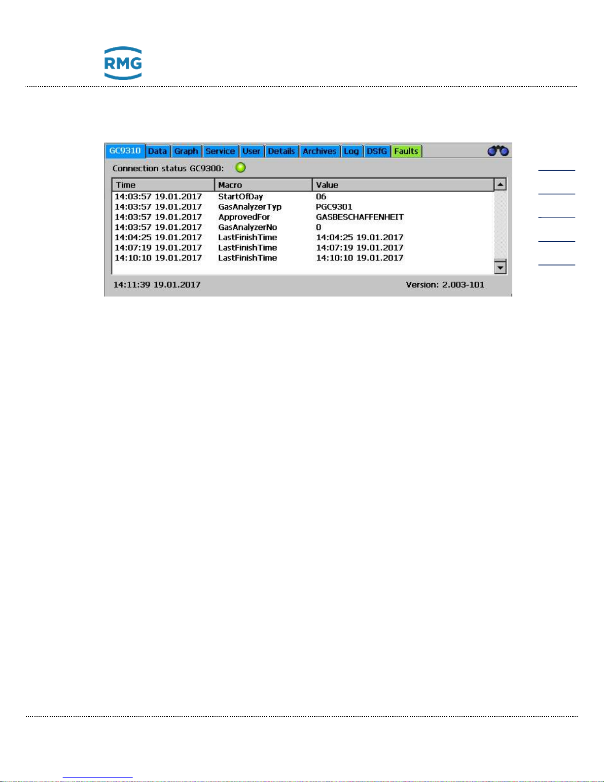
The start screen shows the current status of the GC log. The GC log is used for
communication between the GC 9300 and GC 9310.
The LED shows the status of the GC log:
- Gray: No telegram received from the GC 9300.
- Green: Everything OK. Telegrams are being received regularly from the GC
9300.
- Red: Timeout. No telegrams have been received from the GC 9300 for an
extended time. In this case an alarm is issued simultaneously.
Like the GC 9300, the individual screens are arranged like tabs:
The values that the GC 9310 has received from the GC 9300 are shown in the
table. All operating parameters, the number of the measuring element and the time
stamp of the analyses are shown. The date and time of the device and the software version are displayed at the bottom edge.
GC9310-GW Start screen with status of the GC log
Data Results of the last analysis
Graphs Chromatograms and trends
Service Service functions
User User-specific display
Detail List of all measurements and parameters of the GC 9310
Archive Display of the GC archive
Log Display of the log books
DSfG Display of the DSfG archive
Errors Display of error messages with date and time
Page 36

4 Commissioning
Manual GC 9300 EN14 July, 24th 2018
32
The gateway GC 9310 enables:
• Reading of analysis results
• Displaying and changing operating parameters
• Displaying and saving of analysis results in archives and log books
• Display of chromatograms
• Display of trends
• Display of error messages
• Display of the device status
• Display of the GC log status
• Comprehensive communication functions.
• Calculation (or adoption from the GC 9300) of calorific value, heat value,
standard density, and Wobbe index from the percentages of individual gas
components in accordance with ISO 6976, and the optional calculation of
the methane number.
Like the GC 9300, entry of the code number and/or opening of the custody transfer
switch is normally necessary for nearly all actions other than the display functions.
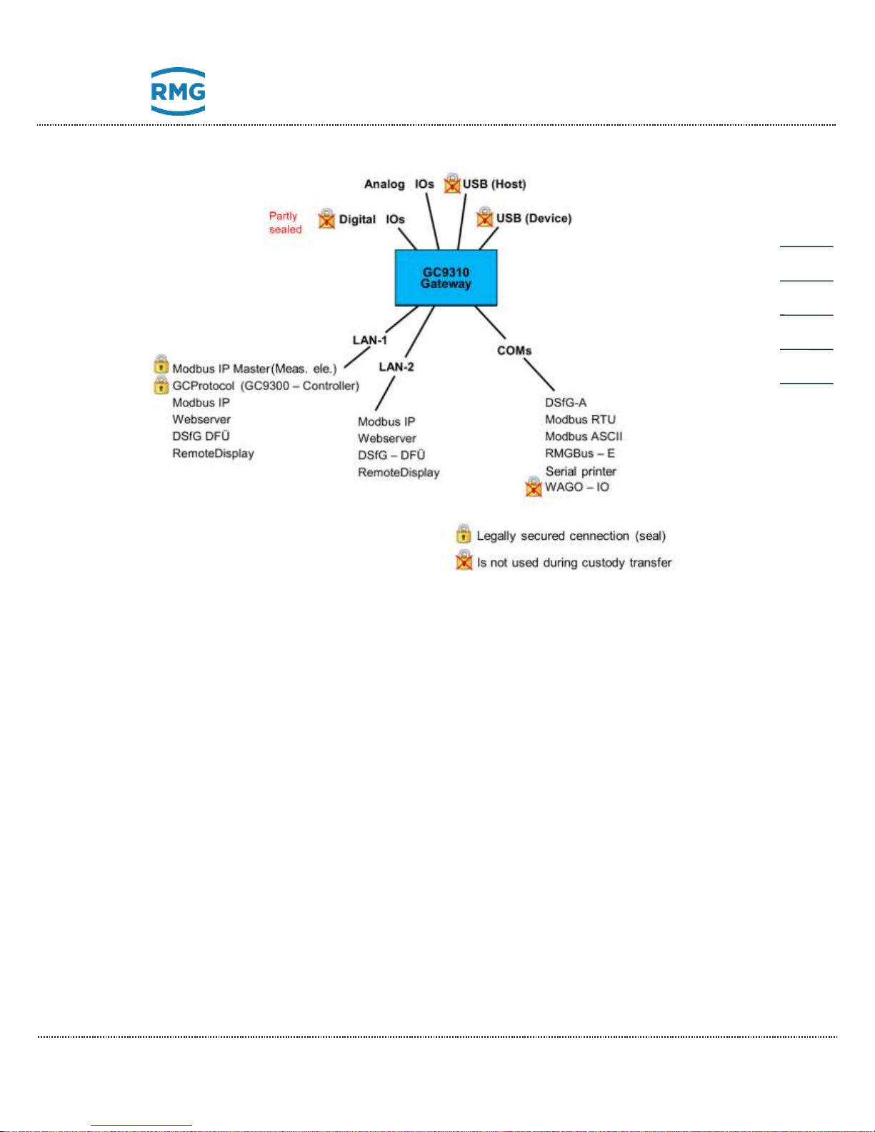
4.2.2 Interfaces and logs
The gateway GC 9310 basically offers the same interfaces and logs as the GC
9300. The GC log for communication between the GC 9300 and GC 9310 has
been recently added. Digital outputs 1-7 (valve control and calibration running)
are omitted. The following figure shows an overview of the interfaces and logs.
Page 37
4 Commissioning
Manual GC 9300 EN14 July, 24th 2018
33
4.2.3 Data storage
The data storage of analysis results is possible in non-custody-transfer measurement archives and in custody transfer archives in accordance with the DSFG
standard; storage is no different than in the GC 9300 (chapter 2.3 Data storage)
Page 38
4 Commissioning
Manual GC 9300 EN14 July, 24th 2018
34
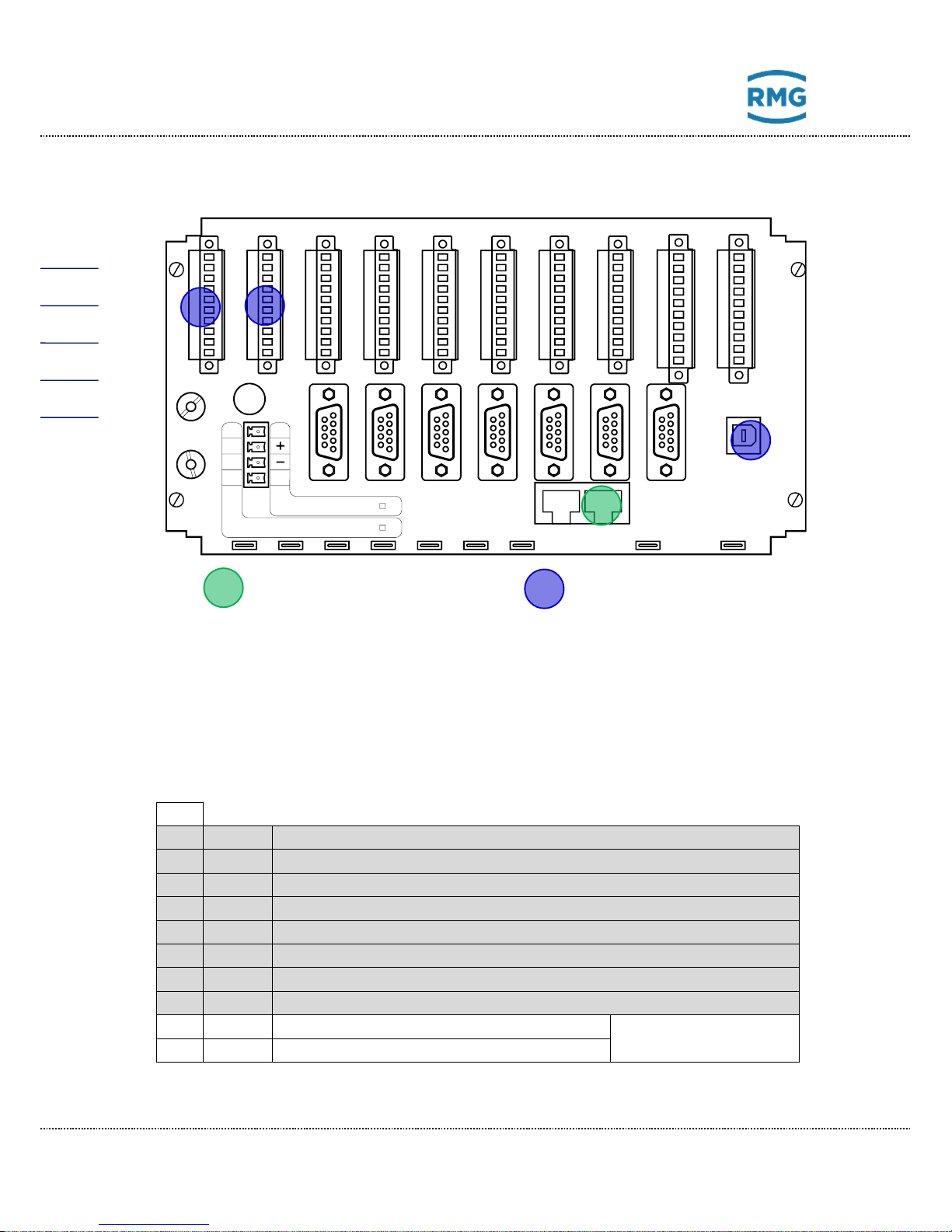
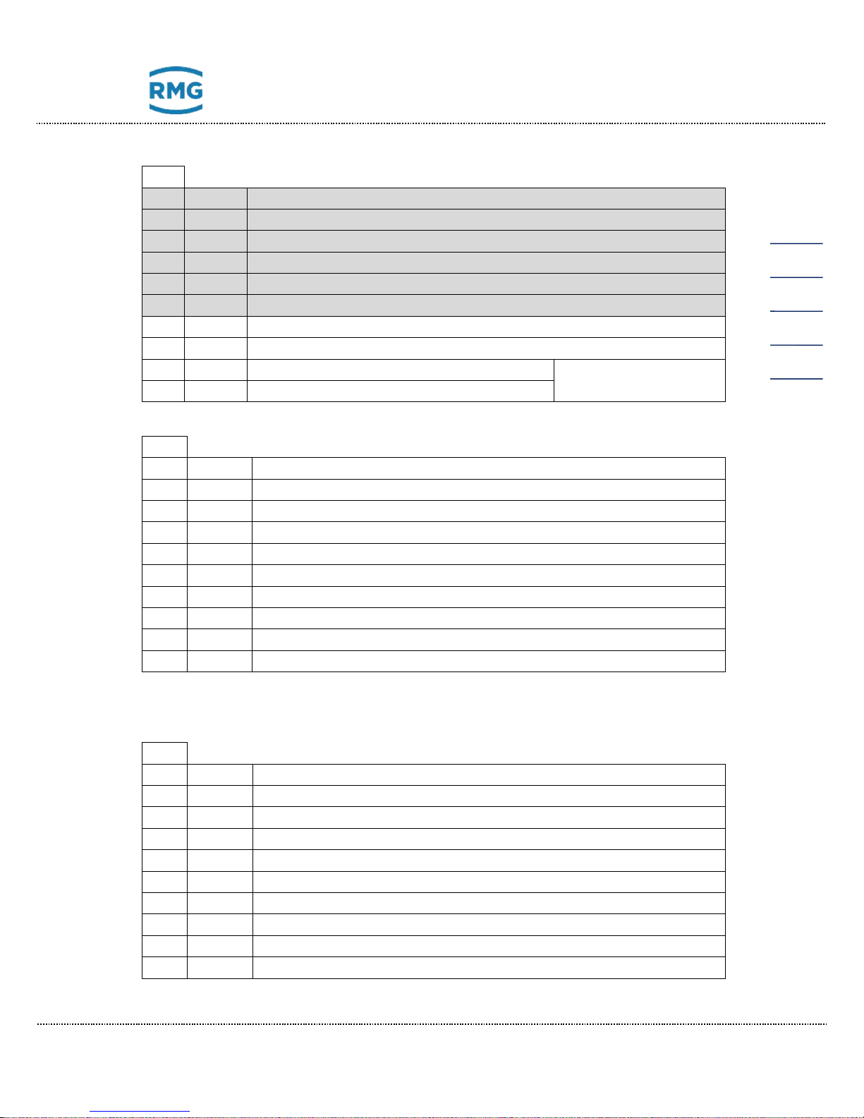
4.2.4 Electrical connections of the GC 9310
The connections are made on the rear wall.
Connection assignment
Pin assignment
X1 1 A1+
Not available
2
A1-
Not available
3
A2+
Not available
4
A2-
Not available
5
A3+
Not available
6
A3-
Not available
7
A4+
Not available
8
A4-
Not available
9
AL+
Alarm contact + PGC: Alarm +
Contact open in the
event of an alarm
10
AL-
Alarm contact - PGC: Alarm -
24VDC F1=2A
100-230VAC F1=1,6A
Ethernet
PE PE
N
L
X19
RMG
X18
X39
USB-D
X16
WA-
WA+
A8-
A8+
A7-
A7+
A6-
A6+
A5-
A5+
5
10
9
8
7
6
4
3
2
1
X2
AL-
AL+
A4-
A4+
A3-
A3+
A2-
A2+
A1-
A1+
5
10
9
8
7
6
4
3
2
1
X1
E11-
E11+
A12-
A12+
A11-
A11+
A10-
A10+
A9-
A9+
5
10
9
8
7
6
4
3
2
1
X3
t1-
t1s
t1s
t1+
I3e
I3e
I2e
I2e
I1e
I1e
5
10
9
8
7
6
4
3
2
1
X5
I8e
I8e
I7e
I7e
I6e
I6e
I5e
I5e
I4e
I4e
5
10
9
8
7
6
4
3
2
1
X6
E5-
E5+
E4-
E4+
E3-
E3+
E2-
E2+
E1-
E1+
5
10
9
8
7
6
4
3
2
1
X7
E10-
E10+
E9-
E9+
E8-
E8+
E7-
E7+
E6-
E6+
5
10
9
8
7
6
4
3
2
1
X8
E12-
E12+
S4-
S4+
S3-
S3+
S2-
S2+
S1-
S1+
5
10
9
8
7
6
4
3
2
1
X4
X11
COM1
X12
COM2
X13
COM3
X14
COM4
COM5
X15
COM6
X37 X38
COM7
F1
Nr. 2 Nr. 1
5
10
9
8
7
6
4
3
2
1
X9
E17-
E17+
E16-
E16+
E15-
E15+
E14-
E14+
E13-
E13+
X10
5
10
9
8
7
6
4
3
2
1
E20-
E20+
E19-
E19+
E18-
E18+
Secured connection
Safety mark (interface
blocked)
Page 39
4 Commissioning
Manual GC 9300 EN14 July, 24th 2018
35
X2 1 A5+
Not available
2
A5-
Not available
3
A6+
Not available
4
A6-
Not available
5
A7+
Not available
6
A7-
Not available
7
A8+
Digital output 8 + Collective message for digital outputs 9 - 12
8
A8-
Digital output 8 - Collective message for digital outputs 9 - 12
9
WA+
Warning contact + PGC: Warning
Contact open in the
event of a warning
10
WA-
Warning contact - PGC: Warning
X3
1
A9+
Digital output 9 + Limit value exceeded analog value 1*
2
A9-
Digital output 9 - Limit value exceeded analog value 1*
3
A10+
Digital output 10 + Limit value exceeded analog value 2*
4
A10-
Digital output 10 - Limit value exceeded analog value 2*
5
A11+
Digital output 11 + Limit value exceeded analog value 3*
6
A11-
Digital output 11 - Limit value exceeded analog value 3*
7
A12+
Digital output 12 + Limit value exceeded analog value 4*
8
A12-
Digital output 12 - Limit value exceeded analog value 4*
9
E11+
Input 11 + (Note: passive input, U
max
= 30 V)
10
E11-
Input 11 – (Note: passive input, U
max
= 30 V)
* The analog values under "Specialties“ can be monitored for limit values. Exceeding these limits
leads to a warning or the setting of a signaling contact.
X4 1 S1+
Current output 1 +
2
S1-
Current output 1 -
3
S2+
Current output 2 +
4
S2-
Current output 2 -
5
S3+
Current output 3 +
6
S3-
Current output 3 -
7
S4+
Current output 4 +
8
S4-
Current output 4 -
9
E12+
Input 12 + (Note: passive input, U
max
= 30 V)
10
E12-
Input 12 – (Note: passive input, U
max
= 30 V)
Page 40
4 Commissioning
Manual GC 9300 EN14 July, 24th 2018
36
X5 Polarity of current inputs depends on operating mode (active/passive).
1
I1e
Current input 1 freely selectable
2
I1e
Current input 1 freely selectable
3
I2e
Current input 2 freely selectable
4
I2e
Current input 2 freely selectable
5
I3e
Current input 3 (active - / passive +)
6
I3e
Current input 3 (active + / passive -)
7
t1+
Temperature input 1 supply ++ Room temperature
8
t1s
Temperature input 1 sense + Room temperature
9
t1s
Temperature input 1 sense - Room temperature
10
t1-
Temperature input 1 supply -- Room temperature
X6 Polarity of current inputs depends on operating mode (active/passive).
1
I4e
Current input 4 (active - / passive +)
2
I4e
Current input 4 (active + / passive -)
3
I5e
Current input 5 freely selectable
4
I5e
Current input 5 freely selectable
5
I6e
Current input 6 (active - / passive +)
6
I6e
Current input 6 (active + / passive -)
7
I7e
Current input 7 / Temperature input 2 supply ++
8
I7e
Current input 7 / Temperature input 2 sense +
9
I8e
Current input 8 / Temperature input 2 sense -
10
I8e
Current input 8 / Temperature input 2 supply --
X7 1 E1+
Digital input 1 + freely selectable
2
E1-
Digital input 1 - freely selectable
3
E2+
Digital input 2 + freely selectable
4
E2-
Digital input 2 - freely selectable
5
E3+
Digital input 3 + freely selectable
6
E3-
Digital input 3 - freely selectable
7
E4+
Digital input 4 + freely selectable
8
E4-
Digital input 4 - freely selectable
9
E5+
Digital input 5 + freely selectable
10
E5-
Digital input 5 - freely selectable
Page 41
4 Commissioning
Manual GC 9300 EN14 July, 24th 2018
37
X8 1 E6+
Digital input 6 + freely selectable
2
E6-
Digital input 6 - freely selectable
3
E7+
Digital input 7 + freely selectable
4
E7-
Digital input 7 - freely selectable
5
E8+
Digital input 8 + freely selectable
6
E8-
Digital input 8 - freely selectable
7
E9+
Digital input 9 + freely selectable
8
E9-
Digital input 9 - freely selectable
9
E10+
Digital input 10 + freely selectable
10
E10-
Digital input 10 - freely selectable
X9 1 E13+
Digital input 13 + freely selectable
2
E13-
Digital input 13 - freely selectable
3
E14+
Digital input 14 + freely selectable
4
E14-
Digital input 14 - freely selectable
5
E15+
Digital input 15 + freely selectable
6
E15-
Digital input 15 - freely selectable
7
E16+
Digital input 16 + freely selectable
8
E16-
Digital input 16 - freely selectable
9
E17+
Digital input 17 + freely selectable
10
E17-
Digital input 17 - freely selectable
X10
1
E13+
Digital input 18 + freely selectable
2
E13-
Digital input 18 - freely selectable
3
E14+
Digital input 19 + freely selectable
4
E14-
Digital input 19 - freely selectable
5
E15+
Digital input 20 + freely selectable
6
E15-
Digital input 20 - freely selectable
7 Not allocated
8 Not allocated
9 Not allocated
10 Not allocated
Page 42
4 Commissioning
Manual GC 9300 EN14 July, 24th 2018
38
Power supply
X16
230 V/AC version
24 V/DC version
L 100 – 230 V
Not allocated
Not allocated
+
+ 24 V
N 100 – 230 V
-
- 24 V
PE
Potential equalization
PE
Potential equalization
Network interfaces
X18:
Ethernet interface 1
For connection with the measuring element CP 4900
X19:
Ethernet interface 2
For connection of a PC or to a local network
Serial interfaces
X11:
COM 1
RS 232 / RS 485*
Modbus RTU / Modbus ASCII
X12:
COM 2
RS 232
WAGO-IO / GPS 170
X13:
COM 3
RS 232 / RS 485*
DSfG / Modbus RTU / Modbus ASCII / RMG-Bus
X14:
COM 4
RS 232 / RS 485*
DSfG / RMG-Bus
X15:
COM 5
RS 232
Modbus RTU / Modbus ASCII
X37:
COM 6
RS 232 / RS 485*
Modbus RTU / Modbus ASCII / RMG-Bus
X38:
COM 7
RS 232 / RS 485*
Modbus RTU / Modbus ASCII
* configurable in the device with jumpers, delivery state in bold text.
Page 43
5 Operation
Manual GC 9300 EN14 July, 24th 2018
39
5 Operation
5.1 Operation on the touch screen
The touch screen enables simple operation via a graphic and largely selfexplanatory user interface. You can jump from any place in the menu to the start
screen with the “HOME” button and then switch back and forth between the start
screen and error screen.
Note
Operate the touch screen directly with your finger or use the supplied plastic
stylus.
Never use hard or sharp objects such as screwdrivers or pens!
There is a risk of scratching or tearing the film of the touch screen.
5.1.1 Start screen
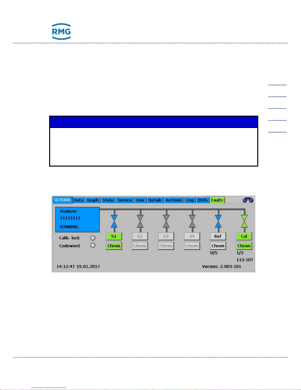
The start screen shows an overview of the current status of the PGC. The following are displayed:
• Error status with color-coding of the “Error” tab
• Ready indicator
o “READY” for “Measuring element is ready”
o “NOT READY” for “Measuring element is not ready”
o “INITIALIZING” for “Measuring element starting up”
Page 44
5 Operation
Manual GC 9300 EN14 July, 24th 2018
40
o “FLUSHING” for “Measuring element flushing in progress”
• Analysis status for gas streams S1 to S4, as well as reference gas and calibrating gas.
• Indication of whether the user lock or custody transfer switch is open.
• Date and time of the device
• Software version
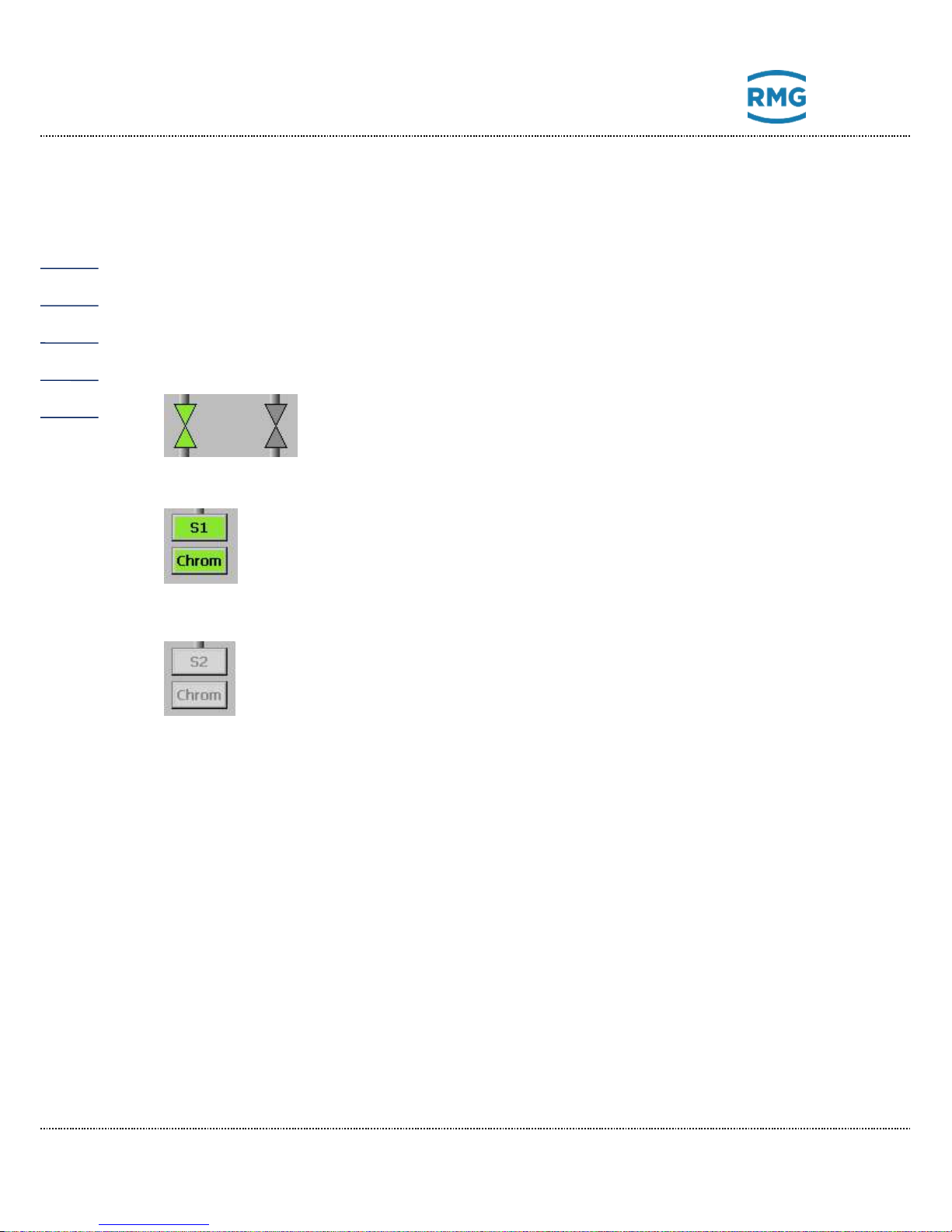
The symbols for the analysis status have the following meanings:
Green: Gas stream is active and switched on
Blue: Gas stream is active and not switched on
Gray: Gas stream is inactive
Green color: The last analysis of this gas flow was error-free.
Grey color and black text:
There is still no measurement result for this gas
stream.
Red color: The last analysis of this gas stream was faulty.
Grey color of the gas stream symbol and gray text mean that
the gas stream is not available for the present version.
S1, Ref and Cal. are always available.
The individual screens are arranged like tabs. They represent the top level of the
operating menu and are accessible via the buttons on the upper edge. The following screens are available:
GC 9300 Start screen
Data Results of the last analysis
Graphs Chromatograms and trends
Status Status displays, measuring element and digital IOs
Service Service functions
User User-specific display
Detail List of all measurements and parameters of the GC 9300
Archive Display of the GC archive
Log Display of the log books
DSfG Display of the DSfG archive
Errors Display of error messages with date and time
Page 45
5 Operation
Manual GC 9300 EN14 July, 24th 2018
41
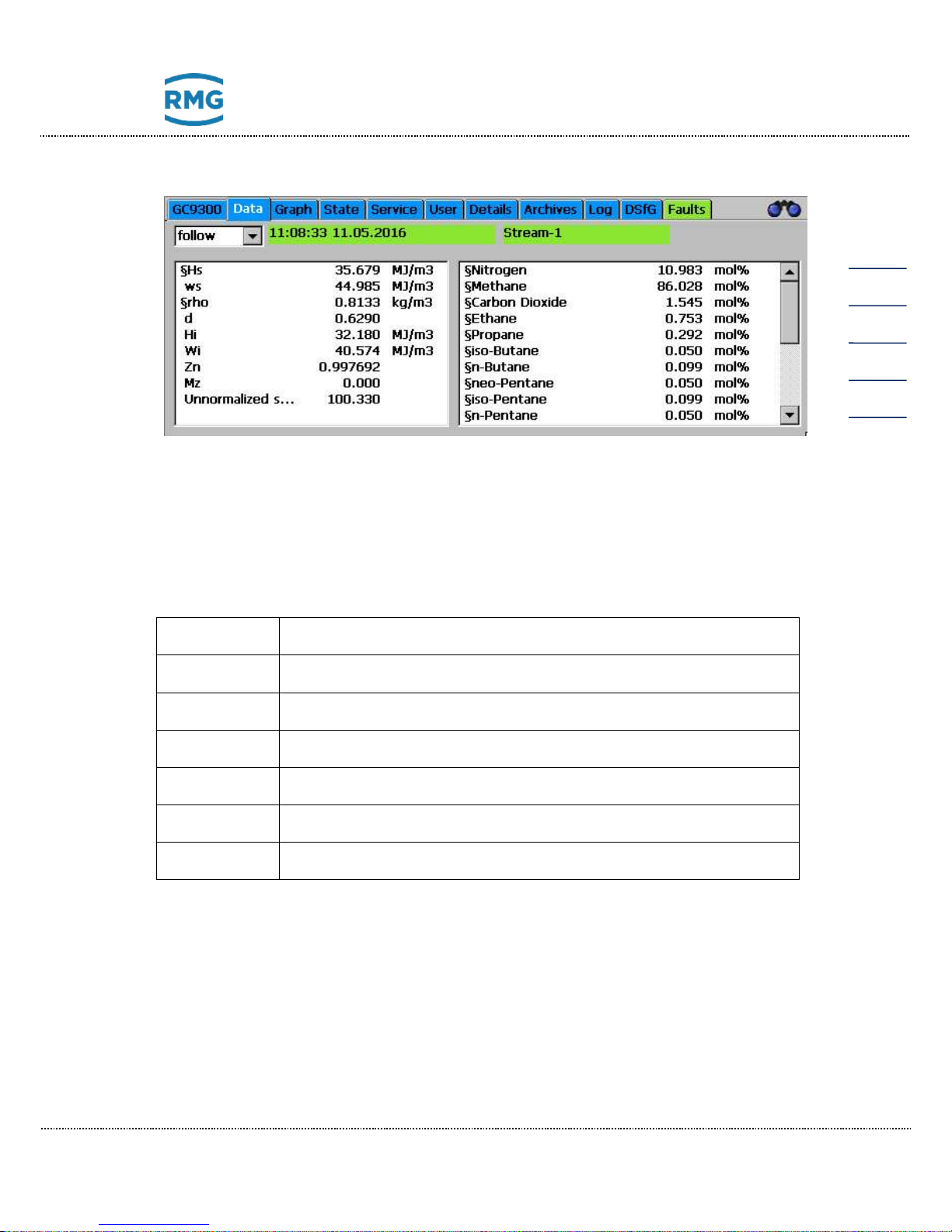
5.1.2 Data: Results of the last analysis
This screen displays the results of the last analysis, the molar content of the gas
components in the right window and values such as calorific value, standard density and Wobbe index that calculated from the molar content in the left window.
The methane number is also shown if its calculation is activated.
The setting for which analysis result is displayed is changed in the selection field
at the top left.
successive
Result of the last analysis, regardless of gas stream or gas type.
Stream-1
Measuring gas from Gas Stream 1
Stream-2
Measuring gas from Gas Stream 2
Stream-3
Measuring gas from Gas Stream 3
Stream-4
Measuring gas from Gas Stream 4
REF gas
Last reference gas analysis
Cal. gas
Last calibration gas analysis
Page 46
5 Operation
Manual GC 9300 EN14 July, 24th 2018
42
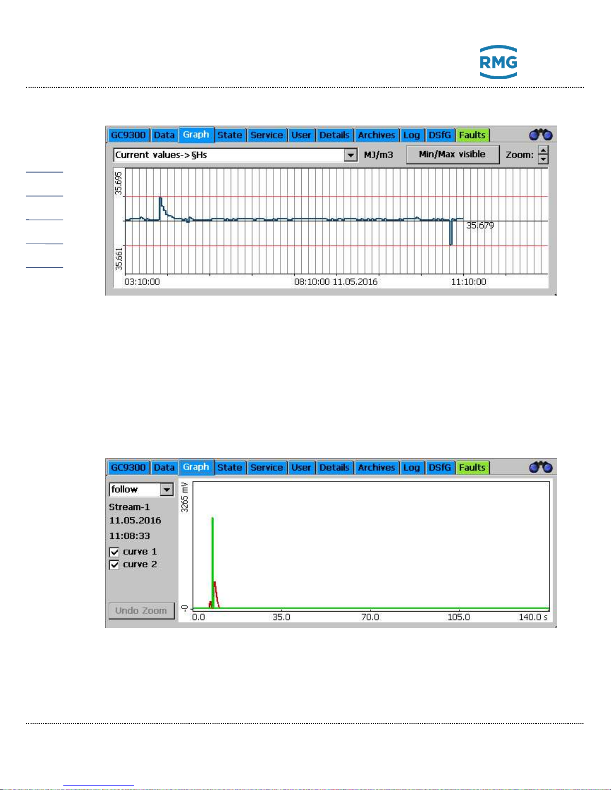
5.1.3 Graph - Trends: Trend display of arbitrary values
The trends of arbitrary values are displayed the “Graph - Trends” screen. Recording takes place for 60 hours (2.5 days). An interval of 10 hours is always displayed.
Specification of which values are recorded should take place under “Archive and
buffer - Trend”. The Modbus address of the value to be recorded must be entered
here.
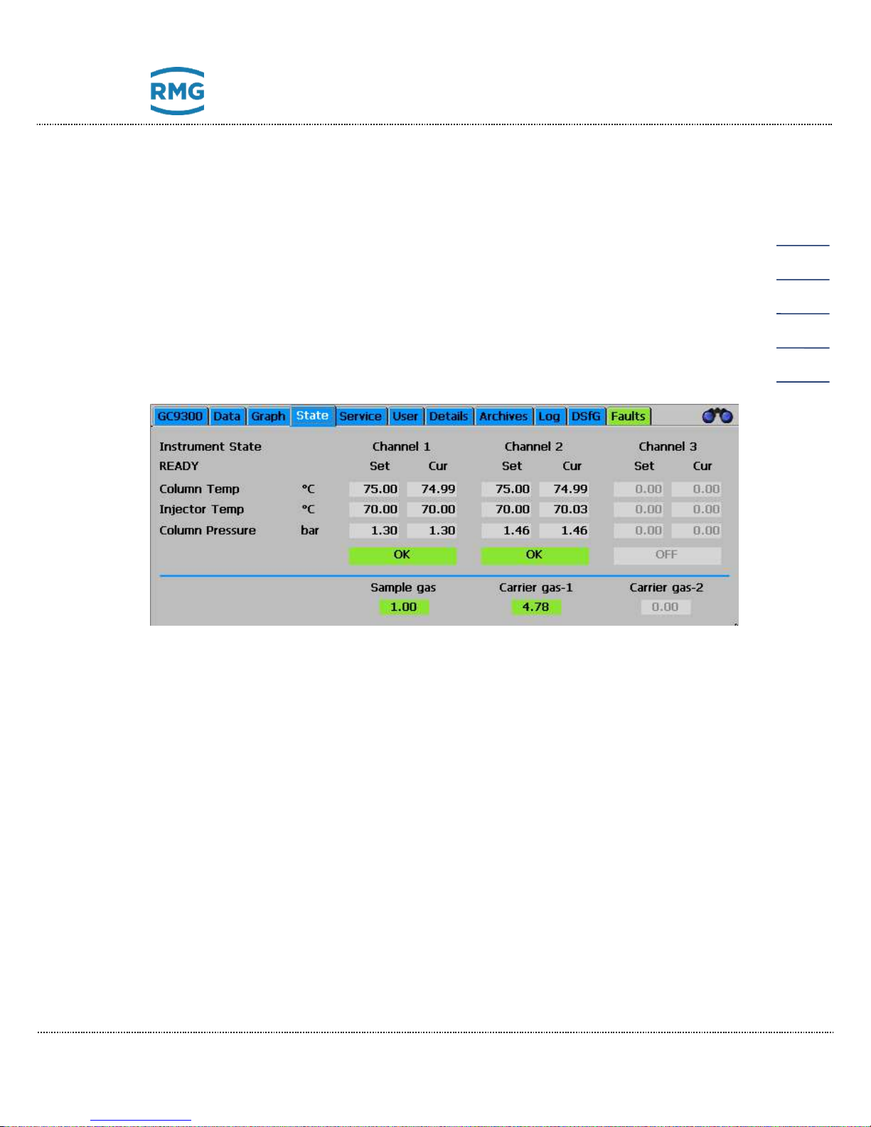
5.1.4 Graph - Chroms: Chromatogram of the last analysis
The chromatograms (signal curves) of the last analysis are displayed in the “Graph
- Chroms” screen. As described under “Data”, the gas stream and/or gas type is
selected in the left selection field. There is a “Reject” selection point here for SKIP
analyses for the purpose the flushing and the corresponding results were not assigned to a gas stream.
Page 47
5 Operation
Manual GC 9300 EN14 July, 24th 2018
43
The measuring element may have 2 or 3 column modules. There is a curve for
each of these modules and they can be displayed individually or together.
Zoom: The scale of the graph can be changed. Press the stylus on the light blue
graphic field and draw a rectangle by moving the stylus. The area within the rectangle is then enlarged. To return to the original standard scale, click on “Undo
zoom”.
5.1.5 Status - Measuring element: Status displays, e.g. column temperature
Variables such as pressure and temperature for Columns 1 to 3 and inlet pressures for measuring gas and carrier gas can be found here for the entries in the
maintenance log. An additional, second carrier gas is used for some applications.
Page 48
5 Operation
Manual GC 9300 EN14 July, 24th 2018
44
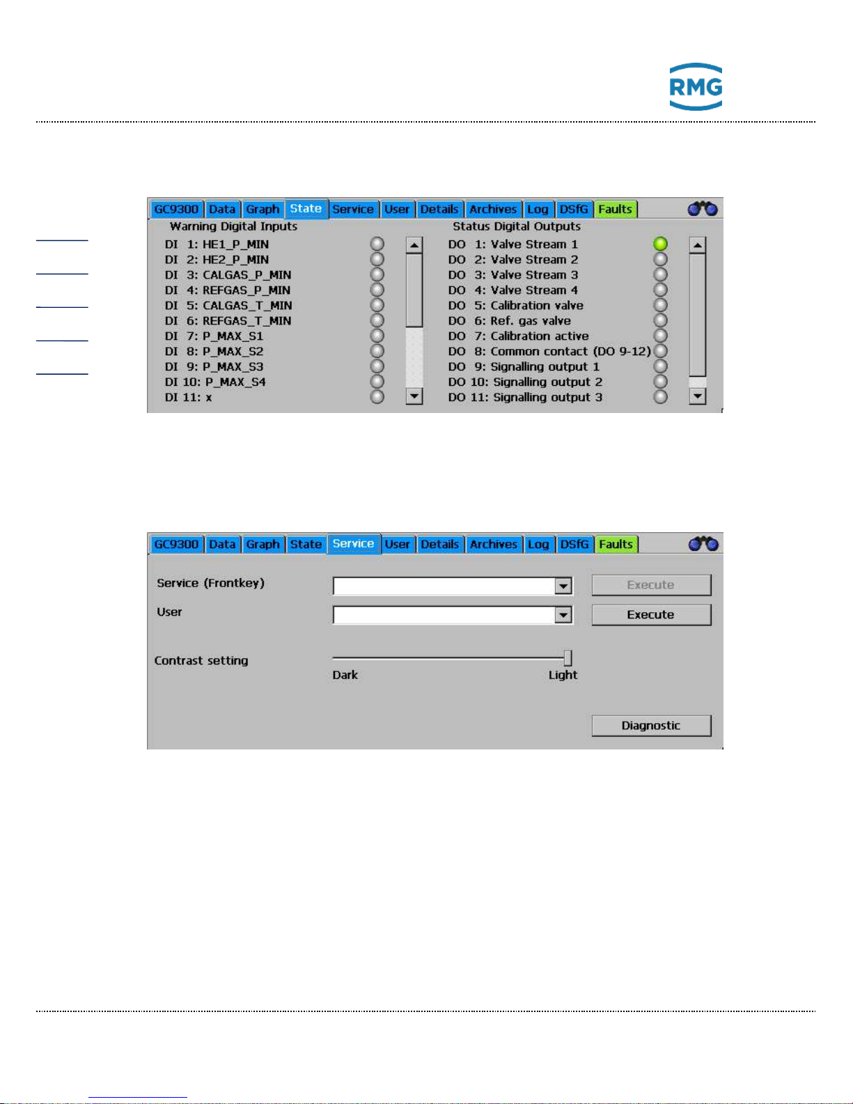
5.1.6 Status – Dig. I/O: Status display of digital inputs and
outputs
The statuses of digital inputs and outputs can be viewed here.
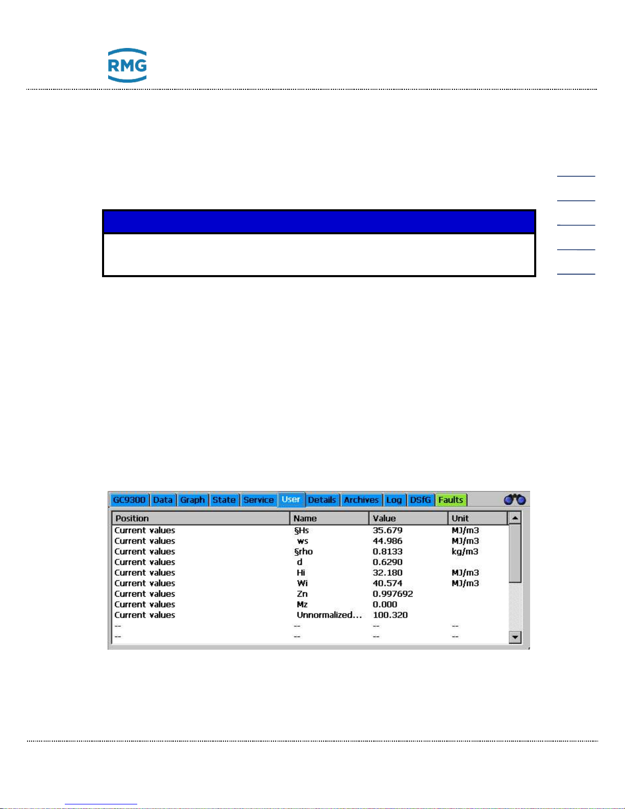
5.1.7 Service: Service functions
Very special settings can be made with the service functions or functions can be
started:
Service (front switch)
The following functions can be selected and started by clicking on the “Execute”
button when the custody transfer switch is open:
a. Custody transfer commissioning
b. Close GC / start Windows Explorer (Close the GC program)
c. Restarting the device
d. Download ERRORLOG.TXT from the measuring element.
Page 49
5 Operation
Manual GC 9300 EN14 July, 24th 2018
45
e. Multilevel import (Import column-specific parameters from the factory cali-
bration)
f. Calculate block CRCs
(A test total for the custody transfer parameters is calculated for each menu
item under “Details”)
g. Bake out the measuring element
Note
These functions a. to g. have major effects on the functionality and are thus
reserved for RMG Service!!
The following functions can be selected by the “normal” user and started by clicking on the “Execute” button.
• Calibrate touch screen:
(Calibration takes place according to the instructions of the operating system and is intended for the correct assignment of contact points for the
graphic elements.)
• Contrast settings
(Slide for adjustment of the screen contrast)
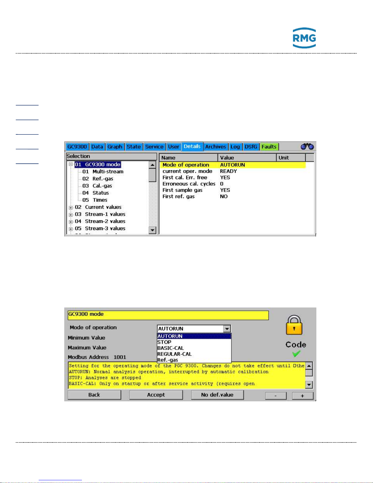
5.1.8 User: User-specific display
The user screen offers the possibility of summarizing 20 arbitrary, frequently
needed measurements for quick display.
Page 50
5 Operation
Manual GC 9300 EN14 July, 24th 2018
46
Selection takes place in the “Detail” screen under “User - Screen”. Then the corre-
sponding Modbus addresses must be specified for each display value. These can
be found by navigating in the “Detail” screen to the respective variable and clicking
on it.
5.1.9 Detail: List of all measurements and parameters of the
GC 9300
A list of all measurements, parameters and operating modes is provided here. The
values are structured in 3 levels and can also be changed with this menu. Navigation to the two upper levels takes place in the left window, then the respective parameters and measurements are displayed in the right window.
When a parameter in the right window is clicked on, a window for changing the
parameter appears:
This window contains fields for entry of variable values or selection fields to
change modes, depending on the type of parameter. In the example above, it is
Page 51
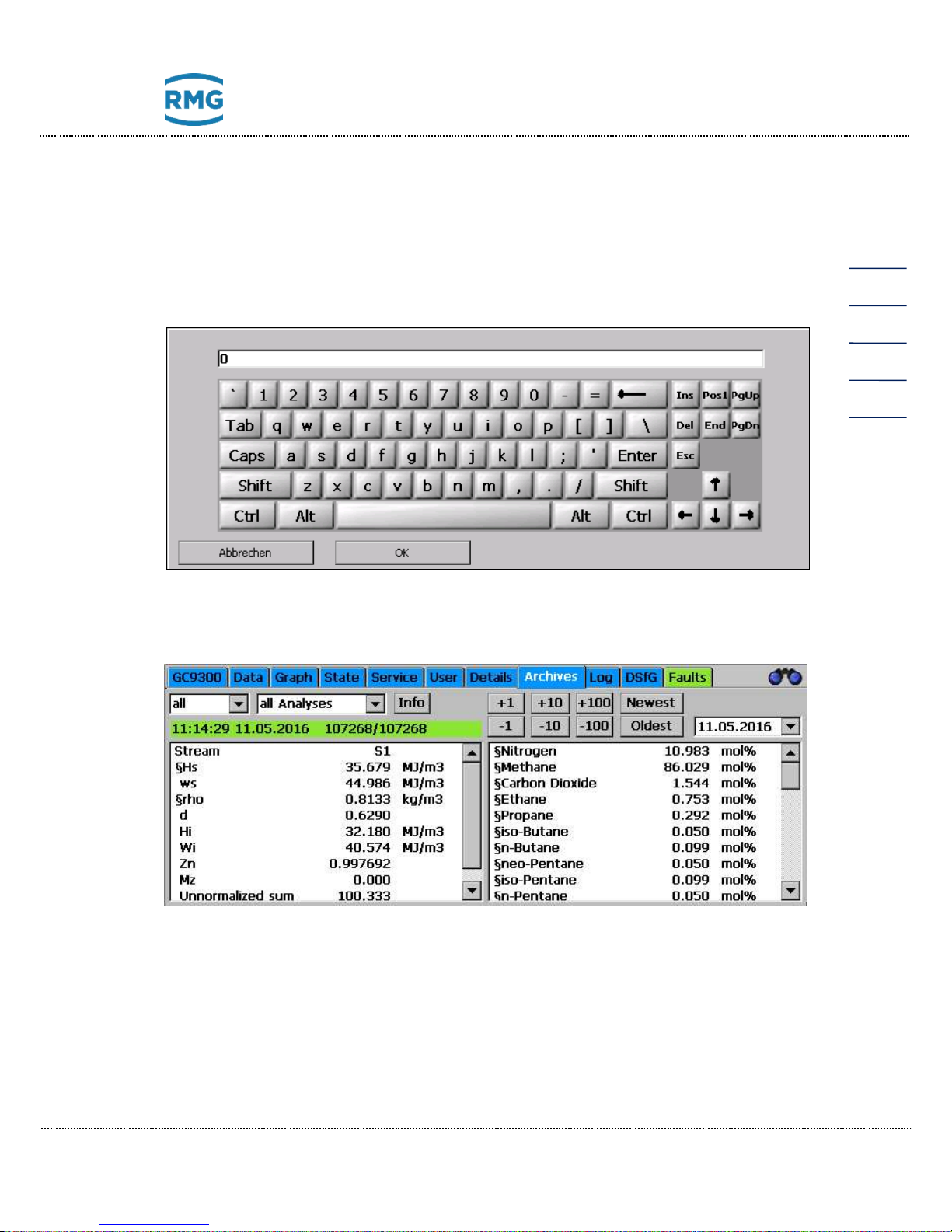
5 Operation
Manual GC 9300 EN14 July, 24th 2018
47
the operating mode that can be adjusted in this manner. In the yellow field below
it, there is a brief description of the parameter, possible with additional information.
The “-” and “+” buttons are used to switch to the previous or next parameter in the
current level.
If a variable value or text should be entered, a keyboard appears once the user
clicks on the corresponding entry field:
5.1.10 Archive: Display of archive entries
All archive entries can be viewed on this screen. A data record with gas components and calculated variables can be displayed on this screen. The desired data
can be filtered as follows with the selection fields:
Left selection field:
• All All conducted analyses, including calibrating and reference gas
• S1 Gas Stream 1
Page 52
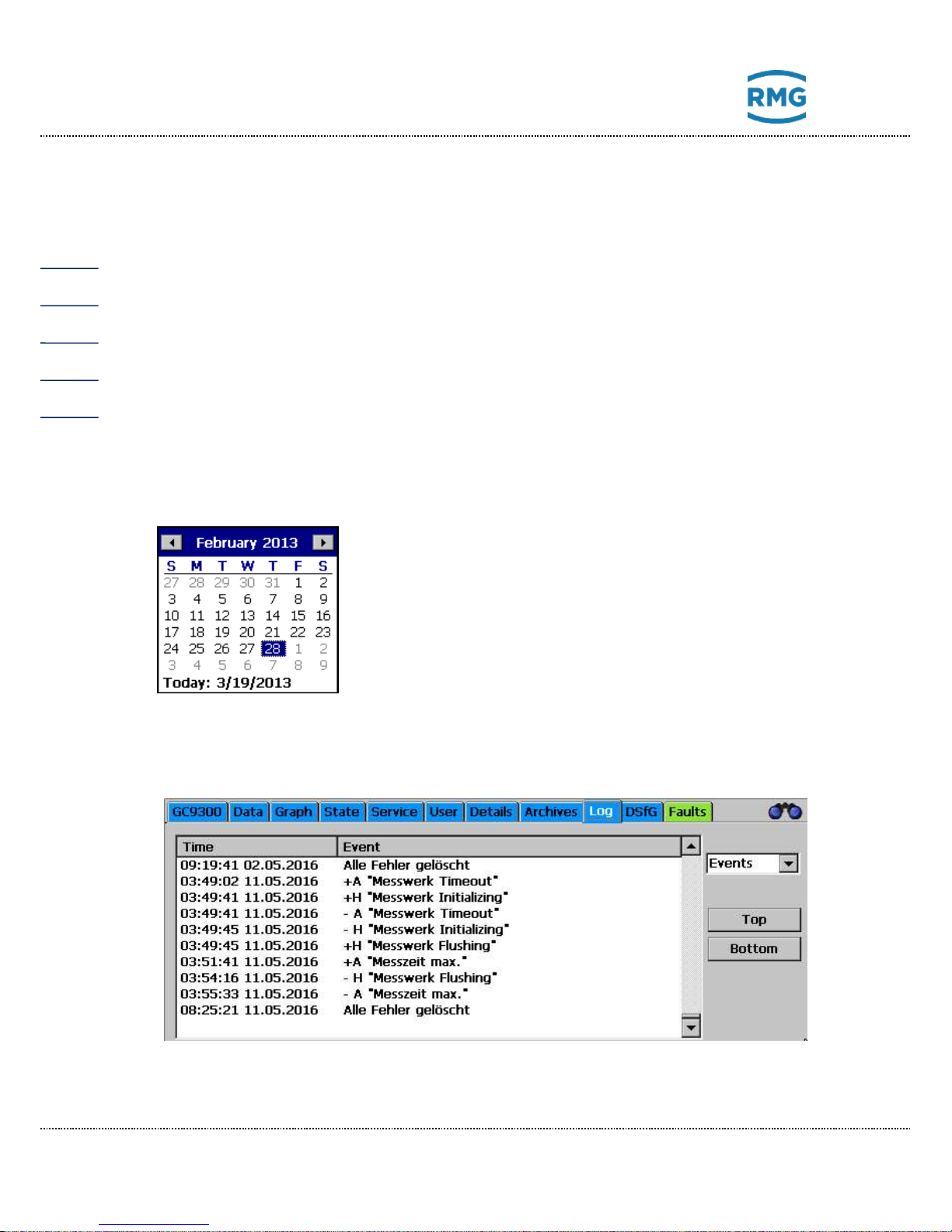
5 Operation
Manual GC 9300 EN14 July, 24th 2018
48
• S2 Gas Stream 2
• S3 Gas Stream 3
• S4 Gas Stream 4
• Ref Reference gas
• Cal Calibrating gas
• Skip Analyses that are not used
Middle selection field:
• Each analysis Display of individual analyses
• Hour Display of the hourly averages
• Day Display of the daily averages
• Month Display of the monthly averages
Right selection field:
A calendar field appears in which the day of the archived
data can be selected.
Then you can jump back one, 10 or 100 entries with the
buttons -100, -10, -1, +1, +10 and +100.
5.1.11 Log: Display of the log books
Page 53
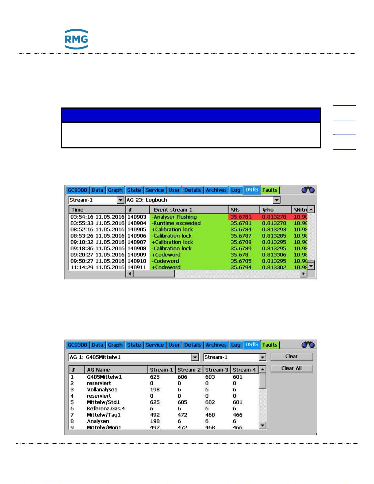
5 Operation
Manual GC 9300 EN14 July, 24th 2018
49
The log books for the PGC are displayed on this screen. With the right selection
field you can switch to:
Events: All events, such as incoming or outgoing alarms with date and time
Parameters: All parameter changes with date and time
Note
Only parameters that are under the code word or the custody transfer switch
are logged.
5.1.12 DSfG - Archive: Display of the DSfG archive
The individual DSfG archive groups can be viewed on the “DSfG - Archive”
screen. The archive groups exist from Stream1 – Stream4.
5.1.13 DSfG - Delete: Deletion of the DSfG archive
Page 54
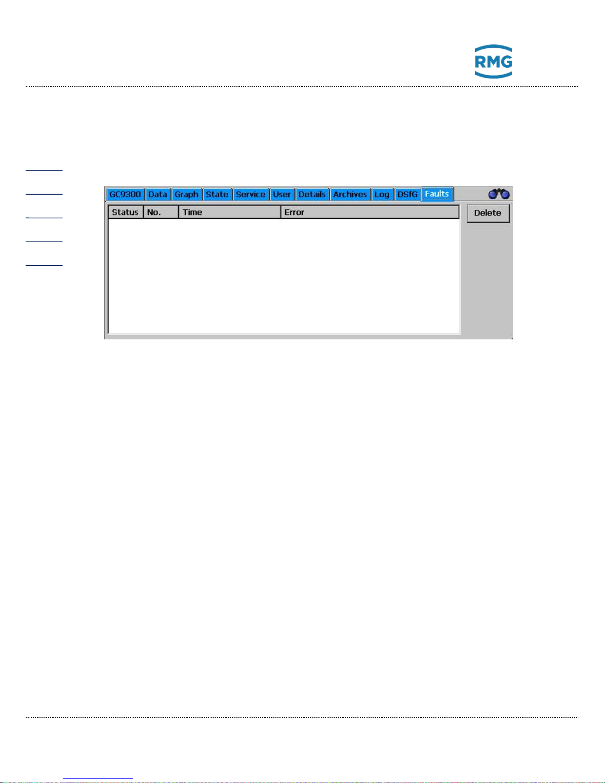
5 Operation
Manual GC 9300 EN14 July, 24th 2018
50
The individual DSfG archives can be deleted stream-by-stream on the “DSfG Delete” screen.
5.1.14 Errors: Display of error messages with date and time
All recently occurring and unacknowledged errors are displayed. Error messages
that are no longer present (green) can be deleted here. Errors with a red background are alarms (A), which means the custody transfer measurement is faulty;
errors with a yellow background are warnings (W), which means the custody transfer measurement has not been affected; notices (N) with a violet background are
information that is unrelated to errors.
The tab is displayed in the color of the error with the highest priority with the display of a different screen:
• Green: no
• Yellow: warning
• Red: alarm
5.2 Operation examples
5.2.1 Enter code number
When changing a large number of parameters, you must first enter the user code.
The default setting is 99999999. Proceed as follows:
I. Open the "Details" screen and scroll down in the window on the left until
"User" appears.
II. Click on the word "User", then on "Codeword" in the window on the right.
III. Enter the user code using the displayed keyboard.
IV. Confirm your input by clicking the "OK" button.
Page 55

5 Operation
Manual GC 9300 EN14 July, 24th 2018
51
V. Click the "Apply" button.
VI. Click the "Back" button to exit the parameterization window.
5.2.2 Change operating mode
To change the operating mode, you must first enter the user code. Stay on the
"Details" screen and proceed as follows:
I. Scroll up to the top of the window on the left.
II. Click on "GC9300 Mode".
III. Click on "Operating Mode" in the window on the right.
IV. Select the desired operating mode in the selection field.
V. Click the "Apply" button.
VI. Click the "Back" button to exit the parameterization window.
The following operating modes are available:
AUTORUN Normal analysis operation. One analysis is performed after
another, interrupted by automatic calibration.
STOP Measurement and calibration operation are disabled.
BASIC-CAL Basic calibration for startup and for RMG service. Basic cali-
bration may not be carried out during normal analysis operation.
NORM-CAL Manual calibration, which can be started at any time and has
the same effect as automatic calibration and also takes 30
minutes. AUTORUN is activated automatically after calibration.
REF-GAS Reference gas analysis, i.e. the reference input for the analy-
sis of test gas or a gas sample is connected. The PGC remains in this mode until it is changed again or the maximimum
of reference gas analysis are done.
After the operating mode is changed, the analysis or calibration currently being
performed is ended and switchover takes place directly afterwards.
Page 56

5 Operation
Manual GC 9300 EN14 July, 24th 2018
52
5.2.3 Program current output
I. To change the operating mode, you must first enter the user code. Stay on
the "Details" screen and proceed as follows:
II. On the "Details" screen, navigate to the measured value that you wish to
output via the current output.
III. In the window on the right, click on the name of the measured value to read
the Modbus address on the parameterization screen. Click "Back" to exit
the parameterization screen.
IV. In the window on the left, scroll to "Inputs and Outputs" and click on it.
V. Scroll down and select one of the four current outputs.
VI. In the window on the right, click on "Operating Mode" and select the desired
operating mode of the current output, e.g. 4-20 mA.
VII. In the window on the right, click on "Select" and enter the Modbus address
of the measured value to be output under "Select" on the parameterization
screen.
VIII. Finally, enter the limits. "Phys. Min. Value" is the measured value for which
the minimum current (0 or 4 mA) is to be output, while "Phys. Max. Value" is
the measured value for the maximum current (20 mA).
IX. The limit value violation should be set to "WARNING" provided the current
output is not being used for custody transfer.
5.2.4 Read values for maintenance log entry
The following values must be read out for the entry in the Maintenance Book:
I. Carrier gas pressure
II. Measuring gas pressure
III. Column temperature
IV. Column pressure
These values can be found on the "Details" screen:
I. In the window on the left, select "Measuring Element/Pressure of Gas for
Analysis". The measuring gas pressure is displayed on the right in the
first line.
II. In the window on the left, select "Measuring Element/Carrier Gas-I". The
carrier gas pressure is displayed on the right in the first line.
Page 57

5 Operation
Manual GC 9300 EN14 July, 24th 2018
53
III. In the window on the left, select "Measuring Element/Channel-I". The
pressure and temperature for column 1 are displayed in the window on
the right.
IV. In "Measuring Element/Channel-2" and "Measuring Element/Channel-3"
you can find the values for other columns.
Page 58
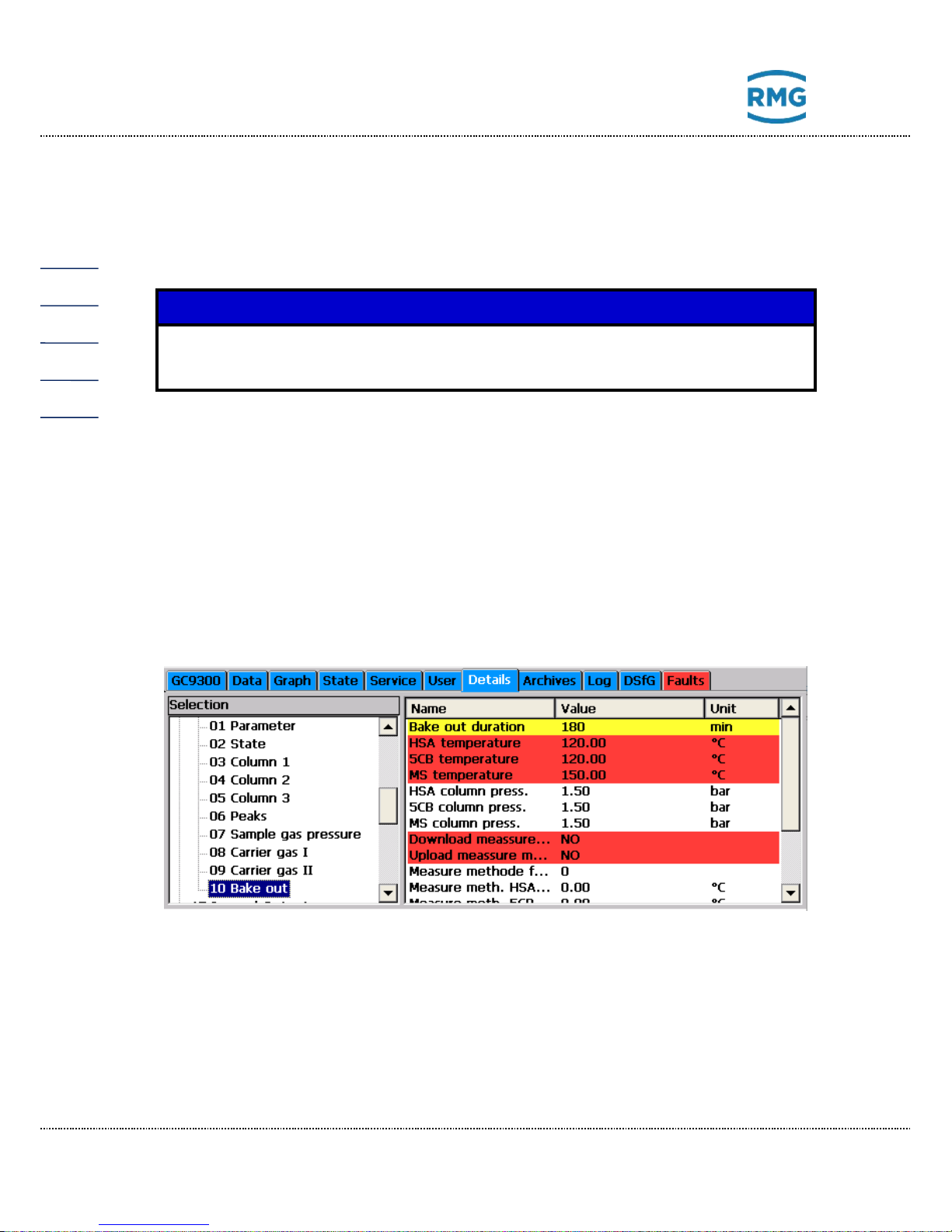
5 Operation
Manual GC 9300 EN14 July, 24th 2018
54
5.3 Bake-out
After a longer service interval or if there is a possibility that impurities from undefined gas mixtures may have entered the measuring element, it is recommended
that the measuring element is baked-out in order to remove these impurities.
Note
If necessary, consult RMG's service department before starting a heating
process.
5.3.1 Bake-out process
As of version V1.610-081, there is a new chapter 14.10 Bake-out under the chapter 14 measurement element.
The duration of the heating process can be entered here. This value is below the
user code word and can be between 180 minutes and 1080 minutes. By default,
this value is set to 180 minutes. The following figure shows the matrix from the
user's point of view.
In the chapter 14.10 Bake-out there are further matrix elements which are not visible in the user profile USER. These additional matrix elements are only visible to
the service.
Before a heating process can be started, the current measuring method from the
measuring element must be saved in the GC9300 controller. This can be done
using the matrix element Upload measurement method in chapter 14.10 Bake-out.
Page 59
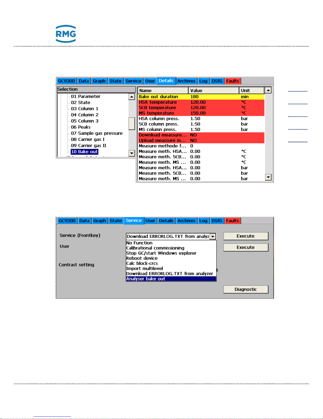
5 Operation
Manual GC 9300 EN14 July, 24th 2018
55
The following figure shows the matrix from a developer's point of view.
The service functions Bake-out the measuring element can be started in the service dialog. The calibration switch must be open in order to perform a service function.
To start the bake-out process, a number of prerequisites must be met:
• The parameters of the measurement method for the connected measuring
element must be stored in the GC9300 controller. (Matrix element: Upload
measurement method)
• The measuring element must be equipped with the column arrangement
HSA - 5CB - MS.
• The operating mode must be set to STOP.
• The carrier gas pressure must be correct. (For PGC9304 carrier gas 1 and -2.)
• The calibration switch must be open in order to start the service function.
Page 60
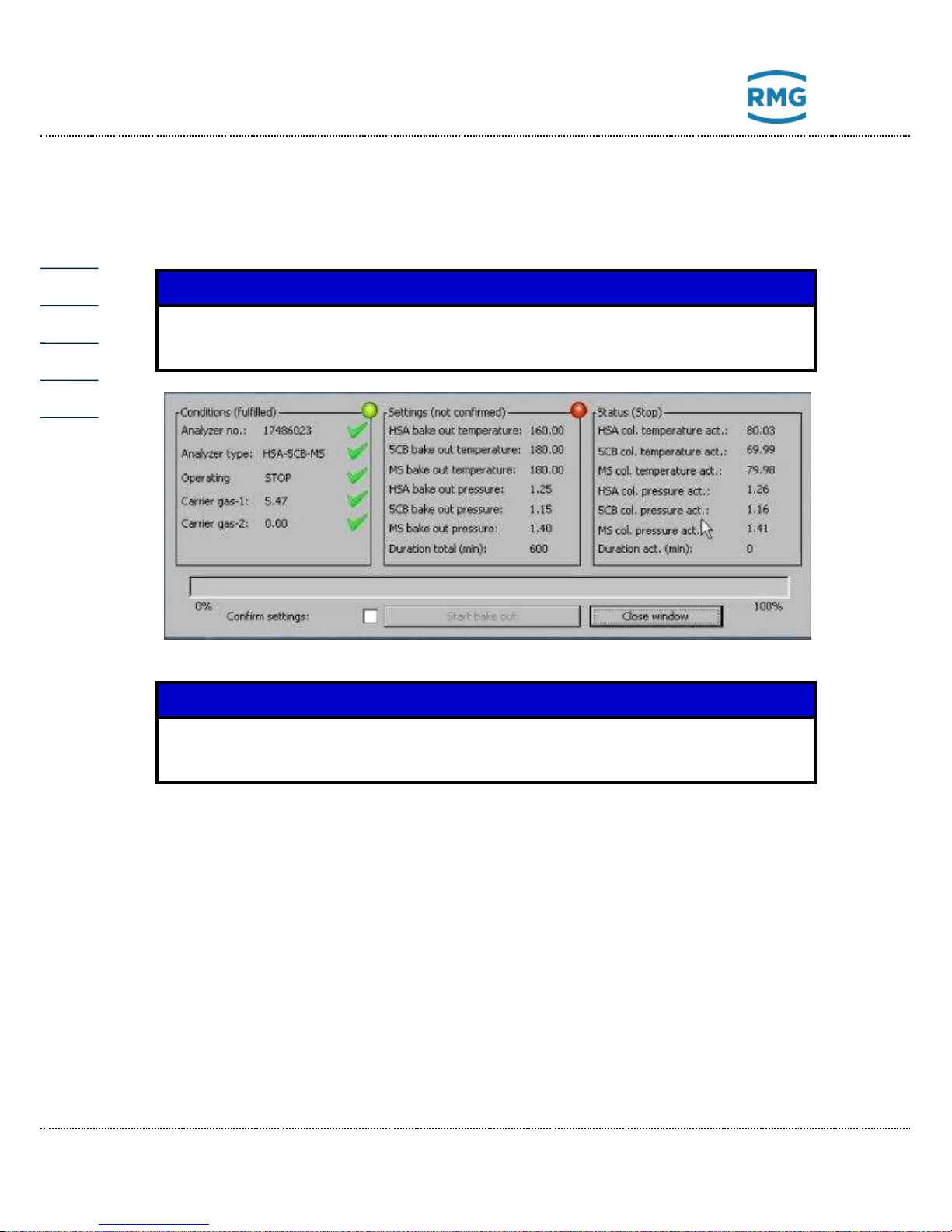
5 Operation
Manual GC 9300 EN14 July, 24th 2018
56
In addition, the settings of the heating procedure must be confirmed:
• column temperatures
• column pressures
• Total duration of the bake-out process
Remark
The following 5 pictures are temporary in German, only. They will be replaced soon.
Note
After the bake-out process has been started, the dialog can no longer be exited.
During the bake-out process, this dialog box contains status indicators that allow
for proper monitoring of the process:
• Current column temperatures
• Current column pressures
• Remaining time of the heating process
• Progress bar
• Status display ("Bake out", "Cool down" and "Equilibrate")
The heating process starts as soon as "Start bake-out process" has been
confirmed twice.
Page 61
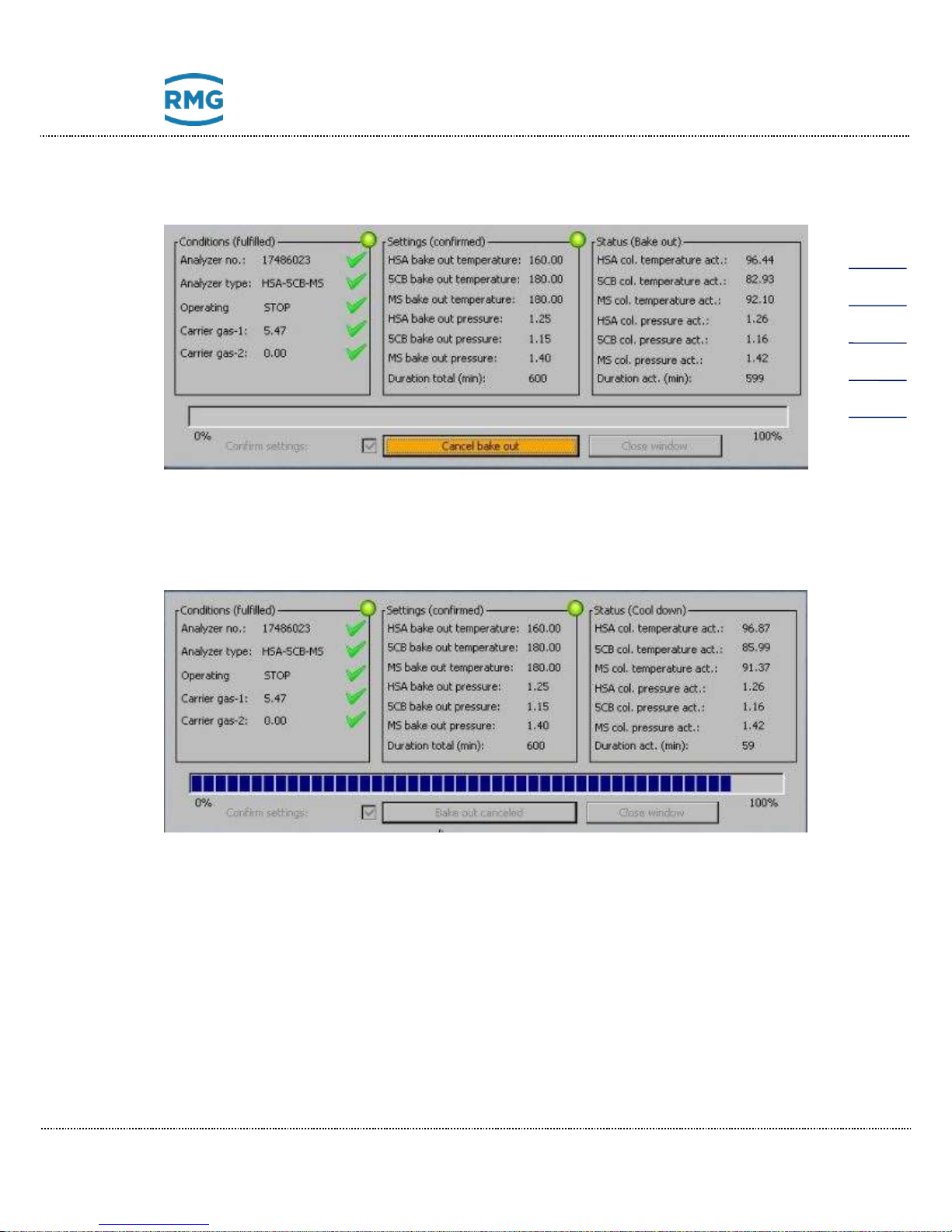
5 Operation
Manual GC 9300 EN14 July, 24th 2018
57
The orange button can be used to stop the heating process. To abort the bake-out
process, "Abort Bake-out" must be confirmed twice.
After termination of the heating process, cooling is started immediately. Now no
more actions and interventions in the cooling process are possible and the cooling
time (always 1 hour) has to be waited.
After cooling has been completed, the dialog box can be left again, regardless of
whether the heating process was interrupted early or whether the heating process
was successfully completed.
Page 62
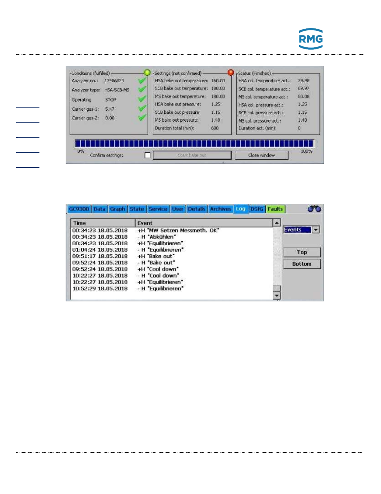
5 Operation
Manual GC 9300 EN14 July, 24th 2018
58
All actions of the heating process were logged into the event log (the timestamps
do not correspond to a real process).
Page 63
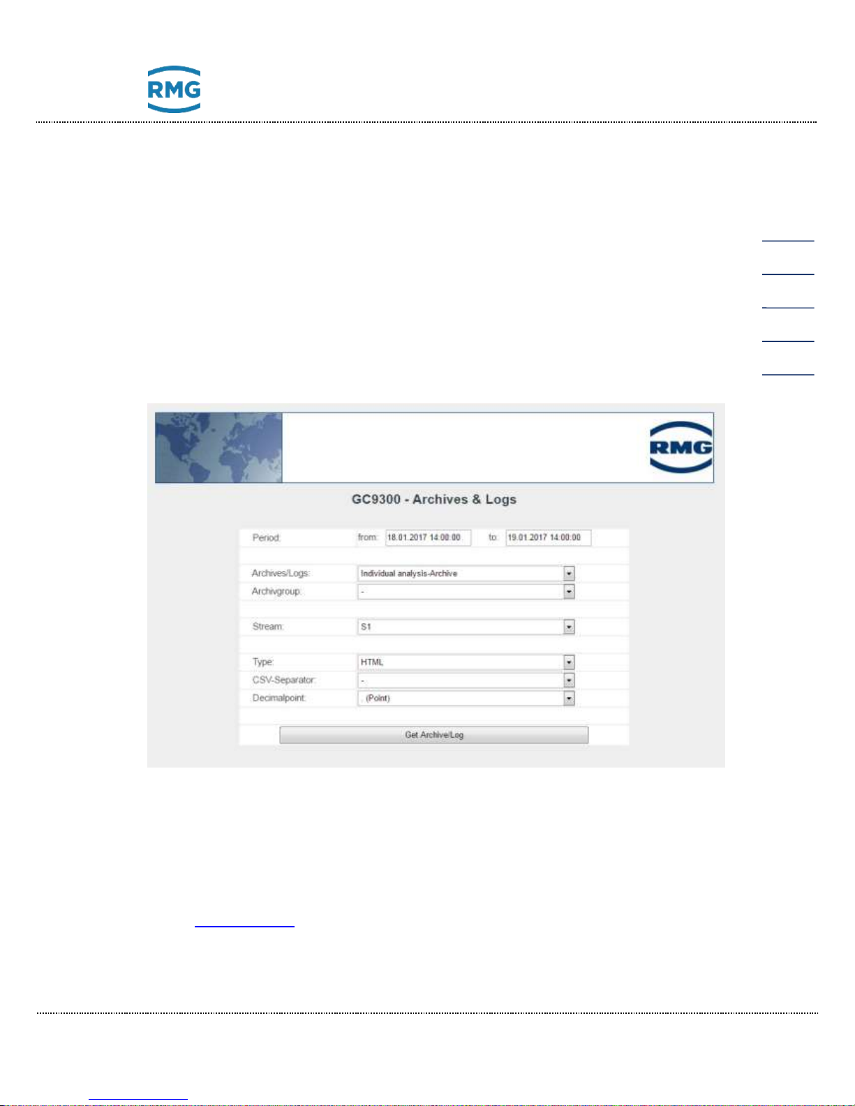
5 Operation
Manual GC 9300 EN14 July, 24th 2018
59
5.4 View and read archive via internet browser
If there is a TCP/IP connection between a PC and the analytical computer, the
archives can be read out with any Internet Browser and the archive content displayed. The archive content can be saved in the file formats html and csv. The
abbreviation "csv" stands for "character-separated values", a format that can be
read by MS Excel.
To get access to the archive data you have to enter a user name and a password.
The user name is always “gcuser” and the password can be set under
“22: Archives, Storage/Web Archive Password”.
Data is read out and viewed from the following window:
5.5 Operation with RMGViewGC
You may find all required information in the manual of RMGViewGC. This manual
can be downloaded from the RMG internet homepage:
www.rmg.com
Reliable Measurement of Gas
Page 64
5 Operation
Manual GC 9300 EN14 July, 24th 2018
60
5.6 Error messages
Error messages are categorized as follows:
A Alarms Custody transfer measurement faults
W Warnings Non-custody transfer function faults
H Hints Messages without faults
Alarm numbers
Internally
DSfG
Type
English
Explanation
1
7001
E
Config file fault
Conflict in parameter assignment/software
2
7002
E
Load signature key
Signature key is loaded
3
424 E ADC out of Range
A/D converter collective fault message for current inputs 1 through 8
8
407 E Reboot GC9300
Temporary power failure
9
407 E Reboot GC9300 (Bios)
Bios started an automatically reboot
10
7010
E
T1 open circuit
Open circuit room temperature measurement
11
7011
E
T2 open circuit
Open circuit room temperature measurement 2
12
7012
E
Temp.-1 alarm limits
Room temperature measurement error
13
7013
E
Temp.-2 alarm limits
Room temperature measurement 2 error
14
621 E Outp current-1 alarm limits
Current output 1: Measured value outside of
limits
15
622 E Outp current-2 alarm limits
Current output 2: Measured value outside of
limits
16
623 E Outp current-3 alarm limits
Current output 3: Measured value outside of
limits
17
624 E Outp current-4 alarm limits
Current output 4: Measured value outside of
limits
20
7020
E
ISO conditions
Input variables for ISO 6976 outside of permitted limits
21
7021
E
GPA conditions
Input variables for GPA 2172-96 outside of
permitted limits
30
7030
E
Nitrogen Min/Max
Ana. & Cal.: Nitrogen content outside of user
limits
31
7031
E
Methane Min/Max
Ana. & Cal.: Methane content outside of user
limits
32
7032
E
Carbon Dioxide Min/Max
Ana. & Cal.: CO2 content outside of user limits
33
7033
E
Ethane Min/Max
Ana. & Cal.: Ethane content outside of user
limits
34
7034
E
Propane Min/Max
Ana. & Cal.: Propane content outside of user
limits
35
7035
E
iso-Butane Min/Max
Ana. & Cal.: i-Butane content outside of user
Page 65
5 Operation
Manual GC 9300 EN14 July, 24th 2018
61
limits
36
7036
E
n-Butane Min/Max
Ana. & Cal.: n-Butane content outside of user
limits
37
7037
E
neo-Pentane Min/Max
Ana. & Cal.: Neopentane content outside of
user limits
38
7038
E
iso-Pentane Min/Max
Ana. & Cal.: i-Pentane content outside of user
limits
39
7039
E
n-Pentane Min/Max
Ana. & Cal.: n-Pentane content outside of user
limits
40
7040
E
C6+ Min/Max
Ana. & Cal.: C6+ content outside of user limits
41
7041
E
n-Hexane Min/Max
Ana. & Cal.: n-Hexane content outside of user
limits
42
7042
E
n-Heptane Min/Max
Ana. & Cal.: n-Heptane content outside of user
limits
43
7043
E
n-Octane Min/Max
Ana. & Cal.: n-Octane content outside of user
limits
44
7044
E
n-Nonane Min/Max
Ana. & Cal.: n-Nonane content outside of user
limits
45
7045
E
Oxygen Min/Max
Ana. & Cal.: Oxygen content outside of user
limits
46
7046
E
Helium Min/Max
Ana. & Cal.: Helium content outside of user
limits
47
7047
E
Hydrogen Min/Max
Ana. & Cal.: Hydrogen content outside of user
limits
48
7048
E
Argon Min/Max
Ana. & Cal.: Argon content outside of user limits
49
7049
E
Reserve Min/Max
(reserve for future functions)
50
7050
E
Gas analyzer TO
Measuring element no longer responding
52
7052
E
Runtime exceeded
Specified maximum analysis time exceeded
53
7053
E
Wrong analyzer unit
Incorrect measuring element connected
60
7060
E
Wago AO1 alarm limits
Alarm limits for Wago analog output 1 violated
61
7061
E
Wago AO2 alarm limits
Alarm limits for Wago analog output 2 violated
62
7062
E
Wago AO3 alarm limits
Alarm limits for Wago analog output 3 violated
63
7063
E
Wago AO4 alarm limits
Alarm limits for Wago analog output 4 violated
64
7064
E
Wago AO5 alarm limits
Alarm limits for Wago analog output 5 violated
65
7065
E
Wago AO6 alarm limits
Alarm limits for Wago analog output 6 violated
66
7066
E
Wago AO7 alarm limits
Alarm limits for Wago analog output 7 violated
67
7067
E
Wago AO8 alarm limits
Alarm limits for Wago analog output 8 violated
68
7068
E
Wago AO9 alarm limits
Alarm limits for Wago analog output 9 violated
69
7069
E
Wago AO10 alarm limits
Alarm limits for Wago analog output 10 violated
70
7070
E
Wago AO11 alarm limits
Alarm limits for Wago analog output 11 violated
71
7071
E
Wago AO12 alarm limits
Alarm limits for Wago analog output 12 violated
72
7072
E
Wago AO13 alarm limits
Alarm limits for Wago analog output 13 violated
73
7073
E
Wago AO14 alarm limits
Alarm limits for Wago analog output 14 violated
74
7074
E
Wago AO15 alarm limits
Alarm limits for Wago analog output 15 violated
Page 66
5 Operation
Manual GC 9300 EN14 July, 24th 2018
62
75
7075
E
Wago AO16 alarm limits
Alarm limits for Wago analog output 16 violated
80
7080
E
Nitrogen §Min/Max
Analysis: Nitrogen content outside of permitted
limits
81
7081
E
Methane §Min/Max
Analysis: Methane content outside of permitted
limits
82
7082
E
Carbon Dioxide §Min/Max
Analysis: CO2 content outside of permitted
limits
83
7083
E
Ethane §Min/Max
Analysis: Ethane content outside of permitted
limits
84
7084
E
Propane §Min/Max
Analysis: Propane content outside of permitted
limits
85
7085
E
iso-Butane §Min/Max
Analysis: i-Butane content outside of permitted
limits
86
7086
E
n-Butane §Min/Max
Analysis: n-Butane content outside of permitted
limits
87
7087
E
neo-Pentane §Min/Max
Analysis: Neopentane content outside of permitted limits
88
7088
E
iso-Pentane §Min/Max
Analysis: i-Pentane content outside of permitted limits
89
7089
E
n-Pentane §Min/Max
Analysis: n-Pentane content outside of permitted limits
90
7090
E
C6+ §Min/Max
Analysis: C6+ content outside of permitted limits
91
7091
E
n-Hexane §Min/Max
Analysis: n-Hexane content outside of permitted limits
92
7092
E
n-Heptane §Min/Max
Analysis: n-Heptane content outside of permitted limits
93
7093
E
n-Octane §Min/Max
Analysis: n-Octane content outside of permitted
limits
94
7094
E
n-Nonane §Min/Max
Analysis: n-Nonane content outside of permitted limits
95
7095
E
Oxygen §Min/Max
Analysis: Oxygen content outside of permitted
limits
96
7096
E
Helium §Min/Max
Analysis: Helium content outside of permitted
limits
97
7097
E
Hydrogen §Min/Max
Analysis: Hydrogen content outside of permitted limits
98
7098
E
Argon §Min/Max
Analysis: Argon content outside of permitted
limits
99
7099
E
Reserve §Min/Max
(reserve for future functions)
100
609 E Cal: retentions time
Calibration: At least one retention time outside
of permitted limits
101
610 E Response factor
Calibration: At least one response factor outside
of permitted limits
Page 67
5 Operation
Manual GC 9300 EN14 July, 24th 2018
63
102
608 E Cal: unnorm. Sum
Calibration: Un-normalized sum outside of permitted limits
103
7103
E
Cal: total area
Calibration: Total area outside of permitted
limits
104
7104
E
Cal: Concentration
Calibration: Collective message for limit value
violation of components
105
7105
E
Cal: Hs limit
Calibration: Superior calorific value outside of
permitted limits
106
7106
E
Cal: rho limit
Calibration: Standard density outside of permitted limits
107
7107
E
Cal: CO2 limit
Calibration: CO2 content outside of permitted
limits
120
7120
E
Ana: retentions time
Analysis: At least one retention time outside of
permitted limits
121
7121
E
Ana: unnorm. Sum
Analysis: Un-normalized sum outside of permitted limits
122
7122
E
Ana: Concentration
Analysis: Collective message for limit value violation of components
123
7123
E
Ana: Hs min/max
Analysis: Superior calorific value outside of
permitted limits
124
7124
E
Ana: Ws min/max
Analysis: Standard density outside of permitted
limits
125
7125
E
Ana: Mz min/max
Analysis: Methane number outside of permitted
limits
126
7126
E
Ana: d min/max
Analysis: Relative density outside of permitted
limits
127
7127
E
Ana: rho min/max
Analysis: Standard density outside of permitted
limits
130
7130
E
Pres. meas. gas at injection
Measuring gas pressure outside of permitted
limits
131
7131
E
Pres. carrier gas -I
Carrier gas pressure 1 (helium) outside of permitted limits
132
7132
E
Pres. carrier gas -II
Carrier gas pressure 2 (argon) outside of permitted limits
133
7133
E
No ana. start bec. of pres.
meas. gas
No start of analysis because measuring gas
pressure outside of permitted limits
150
7150
W
Cal: Concentration
Calibration: Collective message for limit value
violation of components
151
7151
W
Ana: Concentration
Analysis: Collective message for limit value violation of components
152
7152
W
Temp.-1 warning limits
Room temperature measurement error
153
7153
W
Temp.-2 warning limits
(reserve for future functions)
154
7154
W
outp current-1 warning
limits
Current output 1: Measured value outside of
limits
Page 68
5 Operation
Manual GC 9300 EN14 July, 24th 2018
64
155
7155
W
outp current-2 warning
limits
Current output 2: Measured value outside of
limits
156
7156
W
outp current-3 warning
limits
Current output 3: Measured value outside of
limits
157
7157
W
outp current-4 warning
limits
Current output 4: Measured value outside of
limits
158
7158
W
#DiWarnText_0
Warning for digital input 1, text programmable
159
7159
W
#DiWarnText_1
Warning for digital input 2, text programmable
160
7160
W
#DiWarnText_2
Warning for digital input 3, text programmable
161
7161
W
#DiWarnText_3
Warning for digital input 4, text programmable
162
7162
W
#DiWarnText_4
Warning for digital input 5, text programmable
163
7163
W
#DiWarnText_5
Warning for digital input 6, text programmable
164
7164
W
#DiWarnText_6
Warning for digital input 7, text programmable
165
7165
W
#DiWarnText_7
Warning for digital input 8, text programmable
166
7166
W
#DiWarnText_8
Warning for digital input 9, text programmable
167
7167
W
#DiWarnText_9
Warning for digital input 10, text programmable
168
7168
W
#DiWarnText_10
Warning for digital input 11, text programmable
169
7169
W
#DiWarnText_11
Warning for digital input 12, text programmable
170
7170
W
#DiWarnText_12
Warning for digital input 13, text programmable
171
7171
W
#DiWarnText_13
Warning for digital input 14, text programmable
172
7172
W
#DiWarnText_14
Warning for digital input 15, text programmable
173
7173
W
#DiWarnText_15
Warning for digital input 16, text programmable
174
7174
W
#DiWarnText_16
Warning for digital input 17, text programmable
175
7175
W
#DiWarnText_17
Warning for digital input 18, text programmable
176
7176
W
#DiWarnText_18
Warning for digital input 19, text programmable
177
7177
W
#DiWarnText_19
Warning for digital input 20, text programmable
179 0 W
Limit H2S-Sum
Hydrogen sulfide value (analog input) above
permitted limit
180
7180
W
Ana: Nitrogen §Min/Max
Analysis: Nitrogen content outside of permitted
limits
181
7181
W
Ana: Methane §Min/Max
Analysis: Methane content outside of permitted
limits
182
7182
W
Ana: Carbon Dioxide
§Min/Max
Analysis: CO2 content outside of permitted
limits
183
7183
W
Ana: Ethane §Min/Max
Analysis: Ethane content outside of permitted
limits
184
7184
W
Ana: Propane §Min/Max
Analysis: Propane content outside of permitted
limits
185
7185
W
Ana: iso-Butane §Min/Max
Analysis: i-Butane content outside of permitted
limits
186
7186
W
Ana: n-Butane §Min/Max
Analysis: n-Butane content outside of permitted
limits
187
7187
W
Ana: neo-Pentane
§Min/Max
Analysis: Neopentane content outside of permitted limits
Page 69
5 Operation
Manual GC 9300 EN14 July, 24th 2018
65
188
7188
W
Ana: iso-Pentane
§Min/Max
Analysis: i-Pentane content outside of permitted limits
189
7189
W
Ana: n-Pentane §Min/Max
Analysis: n-Pentane content outside of permitted limits
190
7190
W
Ana: C6+ §Min/Max
Analysis: C6+ content outside of permitted limits
191
7191
W
Ana: n-Hexane §Min/Max
Analysis: n-Hexane content outside of permitted limits
192
7192
W
Ana: n-Heptane §Min/Max
Analysis: n-Heptane content outside of permitted limits
193
7193
W
Ana: n-Octane §Min/Max
Analysis: n-Octane content outside of permitted
limits
194
7194
W
Ana: n-Nonane §Min/Max
Analysis: n-Nonane content outside of permitted limits
195
7195
W
Ana: Oxygen §Min/Max
Analysis: Oxygen content outside of permitted
limits
196
7196
W
Ana: Helium §Min/Max
Analysis: Helium content outside of permitted
limits
197
7197
W
Ana: Hydrogen §Min/Max
Analysis: Hydrogen content outside of permitted limits
198
7198
W
Ana: Argon §Min/Max
Analysis: Argon content outside of permitted
limits
199
7199
W
Ana: Reserve §Min/Max
(reserve for future functions)
200
7200
W
Pres. meas. gas
Measuring gas pressure outside of permitted
limits
201
7201
W
Gas analyzer TO
Measuring element not responding
203
7203
W
Too many peaks
Too many peaks in the chromatogram
204
7204
W
Wago AO1 warning limits
Warning limits for Wago analog output 1 violated
205
7205
W
Wago AO2 warning limits
Warning limits for Wago analog output 2 violated
206
7206
W
Wago AO3 warning limits
Warning limits for Wago analog output 3 violated
207
7207
W
Wago AO4 warning limits
Warning limits for Wago analog output 4 violated
208
7208
W
Wago AO5 warning limits
Warning limits for Wago analog output 5 violated
209
7209
W
Wago AO6 warning limits
Warning limits for Wago analog output 6 violated
210
7210
W
Wago AO7 warning limits
Warning limits for Wago analog output 7 violated
211
7211
W
Wago AO8 warning limits
Warning limits for Wago analog output 8 violated
212
7212
W
Wago AO9 warning limits
Warning limits for Wago analog output 9 violated
213
7213
W
Wago AO10 warning limits
Warning limits for Wago analog output 10 vio-
Page 70
5 Operation
Manual GC 9300 EN14 July, 24th 2018
66
lated
214
7214
W
Wago AO11 warning limits
Warning limits for Wago analog output 11 violated
215
7215
W
Wago AO12 warning limits
Warning limits for Wago analog output 12 violated
216
7216
W
Wago AO13 warning limits
Warning limits for Wago analog output 13 violated
217
7217
W
Wago AO14 warning limits
Warning limits for Wago analog output 14 violated
218
7218
W
Wago AO15 warning limits
Warning limits for Wago analog output 15 violated
219
7219
W
Wago AO16 warning limits
Warning limits for Wago analog output 16 violated
220
7220
H
MZ Input values
Input values for methane number calculation
incorrect
221
7221
H
Valve fixed
Mode with fixed valves (for service only) is set
222 0 H
Test mode
PGC runs with recorded data; no analysis
223
7223
H
Cal: Set values
Sum of components in calibration gas not 100%
224
7224
H
Printer not ready
Printer is not ready
225
7225
H
EVars CRC
New checksum (CRC) for custody transfer parameters
227
7227
H
Testmode digital outputs
New checksum (CRC) for secondary parameters
228
7228
H
Calib. val. ferro(CRC)
Test mode for the digital outputs is active
229
7229
H
Calib. val. ferro(version)
Monitoring of the calibration values for inputs
and outputs
230
800 H Calibration lock
Monitoring of the version number for the structure of the inputs and outputs
231
801 H Codeword
Calibration switch open
232
810 H Old Date & Time
Code word entered
233
811 H New Date & Time
Last time before the change
234
802 H Revision
First time after the change
235
7235
H
Write Simufile
Calibration gas or test gas is measured
236
7236
H
Calibrational commissioning
Simulation files are written on SD card
237
7237
H
Ext. test gas
A calibrational commissioning procedure is running
238
7238
H
Waiting time until start
Gas quality measurement of external test gas
240
7240
H
Multilevel import ok
Import of multilevel coefficients successful
241
7241
H
Multilevel import not ok
Import of multilevel coefficients not successful
242
7242
H
Analyser Initializing
Measuring element is presently initializing
243
7243
H
Analyser Flushing
Measuring element is presently flushing
247
760 H Analyser calibrating
Measuring element is presently calibrating
250
7250
H
Chromatogram (FTP)
Error with getting the chromatogram from the
measuring element
Page 71
5 Operation
Manual GC 9300 EN14 July, 24th 2018
67
251
7251
H
FlushChromatogram (FTP)
Error with getting the first chromatogram after
flushing
252
7252
H
Write chromatogram
Error with writing the chromatogram on the SD
card
253
7253
H
Write flushchrom
Error with writing the first chromatogram after
flushing on the SD card
260
7260
H
Bake out
Bake out procedure is running
261
7261
H
Cool down
Cooling down after bake out
262
7262
H
Equilibrieren
Time after bake out until measuring element is
stable again
263
7263
H
Set meas. methode nok
Setting of the measuring method parameters in
the measuring element after bake out failed
264
7264
H
Set meas. methode ok
Setting of the measuring method parameters in
the measuring element after bake out successful
270
7270
H
Parameterlog disabled
No logging of parameter changes
271 0 H
Old time
Old time (after change of the time)
272 0 H
New time
New time (after change of the time)
300
7300
W
Curr. input-1 warning limits
Warning limits for current input 1 violated
301
7301
W
Curr. input-2 warning limits
Warning limits for current input 2 violated
302
7302
W
Curr. input-3 warning limits
Warning limits for current input 3 violated
303
7303
W
Curr. input-4 warning limits
Warning limits for current input 4 violated
304
7304
W
Curr. input-5 warning limits
Warning limits for current input 5 violated
305
7305
W
Curr. input-6 warning limits
Warning limits for current input 6 violated
306
7306
W
Curr. input-7 warning limits
Warning limits for current input 7 violated
307
7307
W
Curr. input-8 warning limits
Warning limits for current input 8 violated
308
7308
W
Abort bake out -> set
meas. methode
Bake out aborted and measuring method loaded
310
7310
W
Wago AI1 warning limits
Warning limits for Wago analog input 1 violated
311
7311
W
Wago AI2 warning limits
Warning limits for Wago analog input 2 violated
312
7312
W
Wago AI3 warning limits
Warning limits for Wago analog input 3 violated
313
7313
W
Wago AI4 warning limits
Warning limits for Wago analog input 4 violated
314
7314
W
Wago AI5 warning limits
Warning limits for Wago analog input 5 violated
315
7315
W
Wago AI6 warning limits
Warning limits for Wago analog input 6 violated
316
7316
W
Wago AI7 warning limits
Warning limits for Wago analog input 7 violated
317
7317
W
Wago AI8 warning limits
Warning limits for Wago analog input 8 violated
318
7318
W
Wago AI9 warning limits
Warning limits for Wago analog input 9 violated
319
7319
W
Wago AI10 warning limits
Warning limits for Wago analog input 10 violated
320
7320
W
Wago AI11 warning limits
Warning limits for Wago analog input 11 violated
321
7321
W
Wago AI12 warning limits
Warning limits for Wago analog input 12 violated
Page 72
5 Operation
Manual GC 9300 EN14 July, 24th 2018
68
322
7322
W
Wago AI13 warning limits
Warning limits for Wago analog input 13 violated
323
7323
W
Wago AI14 warning limits
Warning limits for Wago analog input 14 violated
324
7324
W
Wago AI15 warning limits
Warning limits for Wago analog input 15 violated
325
7325
W
Wago AI16 warning limits
Warning limits for Wago analog input 16 violated
330
7330
W
Multistream parameter
Error with multistream parametrization
331
7331
W
Can't read Dil-Switch
Reading of the Dil switch settings failed
332
7332
W
Explorer running!
Windows Explorer is active
333
7333
W
Saving display calibration
Calibration of the touchscreens has not been
saved
334
7334
W
Software-reboot analyzer
Reboot of the measuring element by the controller
340
7340
W
Nitrogen Min/Max
Ana. & Cal.: Nitrogen content outside of user
limits
341
7341
W
Methane Min/Max
Ana. & Cal.: Methane content outside of user
limits
342
7342
W
Carbon Dioxide Min/Max
Ana. & Cal.: CO2 content outside of user limits
343
7343
W
Ethane Min/Max
Ana. & Cal.: Ethane content outside of user
limits
344
7344
W
Propane Min/Max
Ana. & Cal.: Propane content outside of user
limits
345
7345
W
iso-Butane Min/Max
Ana. & Cal.: i-Butane content outside of user
limits
346
7346
W
n-Butane Min/Max
Ana. & Cal.: n-Butane content outside of user
limits
347
7347
W
neo-Pentane Min/Max
Ana. & Cal.: Neopentane content outside of
user limits
348
7348
W
iso-Pentane Min/Max
Ana. & Cal.: i-Pentane content outside of user
limits
349
7349
W
n-Pentane Min/Max
Ana. & Cal.: n-Pentane content outside of user
limits
350
7350
W
C6+ Min/Max
Ana. & Cal.: C6+ content outside of user limits
351
7351
W
n-Hexane Min/Max
Ana. & Cal.: n-Hexane content outside of user
limits
352
7352
W
n-Heptane Min/Max
Ana. & Cal.: n-Heptane content outside of user
limits
353
7353
W
n-Octane Min/Max
Ana. & Cal.: n-Octane content outside of user
limits
354
7354
W
n-Nonane Min/Max
Ana. & Cal.: n-Nonane content outside of user
limits
355
7355
W
Oxygen Min/Max
Ana. & Cal.: Oxygen content outside of user
limits
356
7356
W
Helium Min/Max
Ana. & Cal.: Helium content outside of user
Page 73
5 Operation
Manual GC 9300 EN14 July, 24th 2018
69
limits
357
7357
W
Hydrogen Min/Max
Ana. & Cal.: Hydrogen content outside of user
limits
358
7358
W
Argon Min/Max
Ana. & Cal.: Argon content outside of user limits
359
7359
W
Reserve Min/Max
(reserve for future functions)
Some messages are listed as both alarms and warnings.
− For the current outputs, you can specify whether they are to be used for custody
transfer (alarm) or not (warning).
− For the limit values there are both warning limits (can be set freely via user
code) and alarm limits (can only be set via calibration switch).
Page 74

6 Technical data
Manual GC 9300 EN14 July, 24th 2018
70
6 Technical data
Housing
19“ slot
Dimensions W x H x D = 213 x 128.4 x 310 mm (42 DU / 3 HU)
Ambient temperature -20 to 55 °C
Power
Power supply 24 V/DC -10%/+15%
Power requirement 25 W
Control panel
Control buttons 1 button (HOME)
Display LCD touchscreen
640 x 240 dots
256 colors
Hardware
Embedded PC CPU ARM1176
Display 533 MHz
128 MB RAM
64 MB Flash
Memory
SD card 4 GB
Operating system
Windows CE 6.0
Digital inputs
Number 20
U
max
5 V
I
max
13 mA
f
max
10 Hz
Surge protection 6.8 V
Page 75

6 Technical data
Manual GC 9300 EN14 July, 24th 2018
71
Digital outputs
Number 12
U
max
24 V
I
max
100 mA
P
max
100 mW
Surge protection 33 V
Current inputs
Number 8
Resolution 20-bit
U
max
2.5 V
Ri 250 ohms
Surge protection 6.8 V
Current outputs
Number 4
Resolution 12-bit
Load 700 ohms
Surge protection 33 V
Data interfaces
Ethernet (2x)
LAN 1 RMG network, measuring element connection
DHCP server, DHCP client or fixed IP address
LAN 2 Operator network
DHCP client or fixed IP address
USB (2x)
Front For mouse, ext. hard disk or keyboard
Rear panel For connection of a PC
Serial (7x)
COM 1 RS 232 / RS 485, configurable by jumpers
COM 2 RS 232
COM 3 RS 232 / RS 485, configurable by jumpers
COM 4 RS 232 / RS 485, configurable by jumpers
COM 5 RS 232
COM 6 RS 232 / RS 485, configurable by jumpers
COM 7 RS 232 / RS 485, configurable by jumpers
Page 76

Appendix
Manual GC 9300 EN14 July, 24th 2018
72
Appendix
Appendix A: List of parameters
The "Parameter list" is in a separate part of the manual called:
PGC9300_AC_Parameter_en_12
This section of the manual can be accessed and downloaded – if required – from the
homepage:
www.rmg.com
Page 77

Appendix
Manual GC 9300 EN14 July, 24th 2018
73
Page 78

Contact
Manual GC 9300 EN14 July, 24th 2018
Subject to technical modifications
For further information
If you would like to learn more
about the products and solutions
from RMG, please visit our website:
www.rmg.com
or your local support office
or contact your local sales representative
RMG Messtechnik GmbH
Otto-Hahn-Straße 5
35510 Butzbach, Germany
Phone: +49 (0) 6033 897 – 0
Fax: +49 (0) 6033 897 – 130
Email: [email protected]
 Loading...