

Page 1
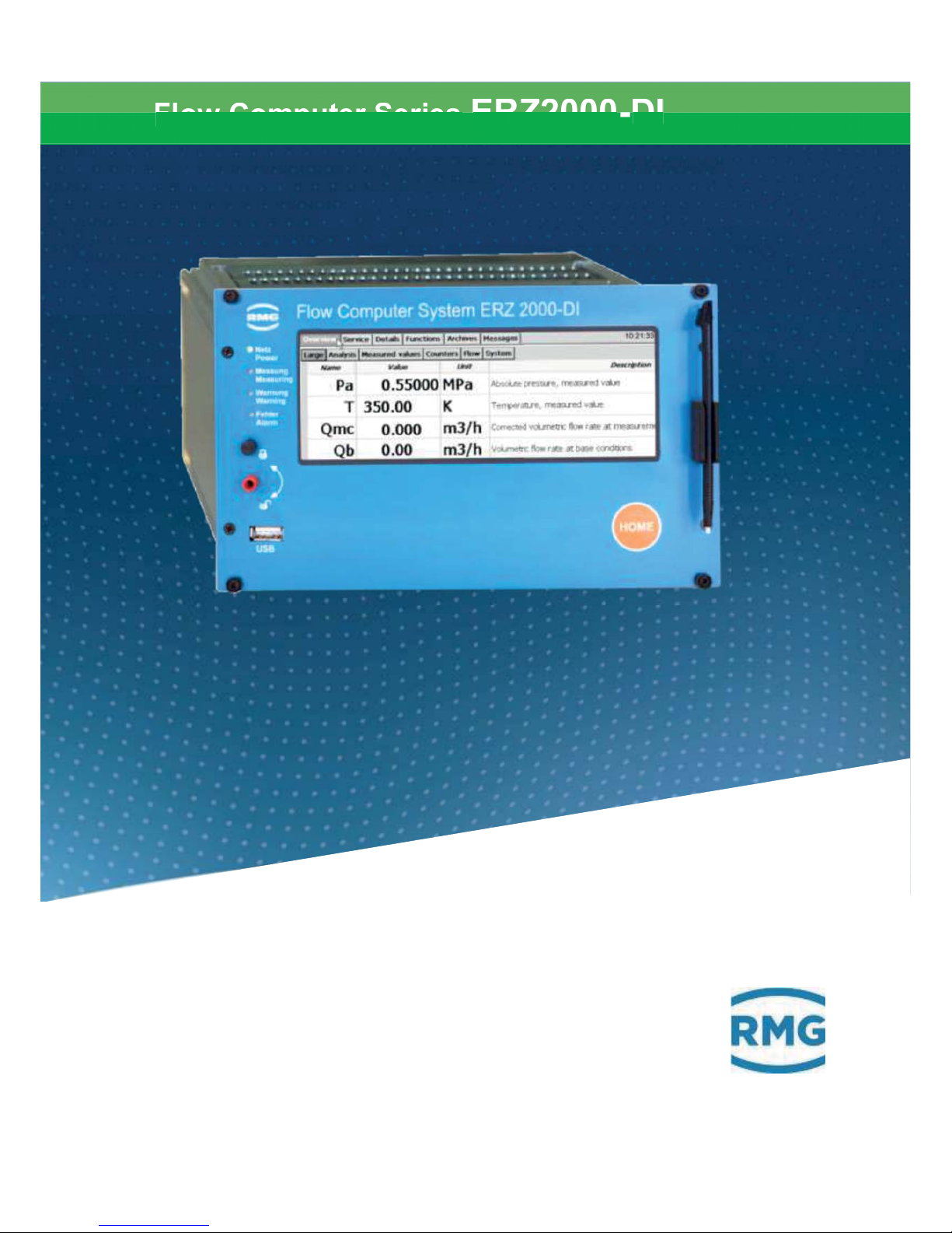
Flow Computer Series ERZ2000-DI
Computer Series
Issued: 2017, DECEMBER 15th
Version:
1.2
Firmware version: 1.0
Reliable Measurement of Gas
OPERATING MANUAL
Page 2
Manual ERZ2000-DI · EN1.2 · 2017, December 21st
Manufacturer
Contact our customer service department
for technical information.
Address
RMG Messtechnik GmbH
Otto-Hahn-Straße 5
D-35510 Butzbach (Germany)
Main office
+49 6033 897 – 0
Service
+49 6033 897 – 127
Spare parts
+49 6033 897 – 173
Fax
+49 6033 897 – 130
Email
Translation of the
original document
The manual ERZ2000DI_manual_en_1_2 of
2017, December 21
st
for the flow computer
ERZ2000
-DI is the document
translated first from the
German original version. Anyhow, this document may
serve as reference for translations into other languages. Please use in case of any uncertainties the
German version as main reference.
Note
Unfortunately, paper is not updated automatically,
whereas technical development continuously advances. Therefore, we reserve the right to make technical changes in regard to the representations and
specifications of this operating manual. The latest version of this manual (and other devices) can be downloaded at your convenience from our Internet page:
www.rmg.com.
Created
2017, December 21st
1. Revised
Document version and
language
Document
version
ERZ2000DI_manual_en_1_2
2017, December 21st
Language
EN
Page 3

TABLE OF CONTENTS
Manual ERZ2000-DI · EN1.2 · 2017, December 21st
TABLE OF CONTENTS
1 ABOUT THIS MANUAL ..................... 1
1.1 Structure of the manual .............................................................................. 1
1.2 Purpose of the manual ................................................................................ 2
1.2.1 Abbreviations ......................................................................................................... 2
1.2.2 Structure of notices ................................................................................................ 4
1.2.3 Working with the device ......................................................................................... 5
1.2.4 Risk assessment and minimization ........................................................................ 9
1.2.5 Applicability of the manual ................................................................................... 10
1.2.6 Transport .............................................................................................................. 11
1.2.7 Scope of delivery .................................................................................................. 11
1.2.8 Disposal of packaging material ............................................................................ 12
1.2.9 Storage ................................................................................................................. 12
1.3 Function...................................................................................................... 13
1.4 Overview ..................................................................................................... 14
1.5 Areas of application .................................................................................. 15
1.5.1 Use in gas measurement technology ................................................................... 15
1.5.2 Seal diagram for devices with MID approval ........................................................ 17
1.5.3 Signature, software and hardware data ............................................................... 18
2 INTRODUCTION .............................. 19
2.1 Operation .................................................................................................... 19
2.1.1 Front panel ........................................................................................................... 19
2.1.2 Operation on the touch screen ............................................................................. 20
2.1.3 Remote control / parameterization ....................................................................... 20
2.1.4 Operation on the home page ............................................................................... 27
2.2 Adjustment of the ERZ2000-DI via wizard ............................................... 28
2.3 Browser home page and coordinate system ........................................... 32
2.3.1 Large representation in the display ...................................................................... 32
2.3.2 Further specifications in the home page .............................................................. 34
2.3.3 Display ................................................................................................................. 41
2.4 Access protection for data and settings.................................................. 46
2.5 Language setting ....................................................................................... 50
2.6 Screen saver .............................................................................................. 50
2.7 Display screen ........................................................................................... 50
2.7.1 Overview .............................................................................................................. 52
2.7.2 Service ................................................................................................................. 55
2.7.3 Details .................................................................................................................. 56
2.7.4 Functions .............................................................................................................. 57
Page 4

TABLE OF CONTENTS
Manual ERZ2000-DI · EN1.2 · 2017, December 21st
2.7.5 Archive ................................................................................................................. 66
2.7.6 Alarm, warning message ...................................................................................... 70
2.7.7 Highest load display ............................................................................................. 72
2.8 Time system ............................................................................................... 72
2.8.1 IB Time, date ........................................................................................................ 72
2.8.2 IC Time synchronization ....................................................................................... 72
3 ELECTRICAL CONNECTIONS ....... 73
3.1.1 Equipment variants .............................................................................................. 73
3.1.2 Terminal assignment ............................................................................................ 76
3.1.3 Data interfaces ..................................................................................................... 79
3.1.4 Pin assignment and usage recommendation of the interfaces ............................ 80
3.1.5 External modem connection ................................................................................. 81
3.1.6 Connections ......................................................................................................... 84
3.1.7 Assignment of "physical values" .......................................................................... 87
3.1.8 Software and hardware identification ................................................................... 88
4 TRANSMITTERS ............................. 90
4.1 Flow meters ................................................................................................ 90
4.1.1 Turbine wheel gas meters .................................................................................... 90
4.1.2 Ultrasonic gas meters .......................................................................................... 92
5 SPECIAL COORDINATES .............. 94
5.1.1 KI Hourly amounts ................................................................................................ 94
5.2 Documentation ........................................................................................... 96
5.2.1 Matrix ................................................................................................................... 96
5.2.2 Document creation ............................................................................................... 97
5.2.3 Documentation ..................................................................................................... 98
5.3 Parameterization ........................................................................................ 99
5.3.1 Parameterizing data ............................................................................................. 99
5.3.2 Calibration data .................................................................................................. 100
5.3.3 Changes ............................................................................................................. 101
5.3.4 Save and load .................................................................................................... 102
5.4 Other ......................................................................................................... 103
5.4.1 Error display ....................................................................................................... 103
5.4.2 Freeze values ..................................................................................................... 104
5.4.3 Interface variables .............................................................................................. 105
5.4.4 Log book ............................................................................................................ 106
5.4.5 Binary code check .............................................................................................. 106
5.4.6 TSV export ......................................................................................................... 107
5.4.7 Exceptions .......................................................................................................... 108
6 ERRORS ........................................ 108
Page 5

TABLE OF CONTENTS
Manual ERZ2000-DI · EN1.2 · 2017, December 21st
6.1 Error settings ........................................................................................... 108
6.1.1 YL error messages ............................................................................................. 108
6.2 Error list .................................................................................................... 109
APPENDIX ......................................... 116
A) Updating software ................................................................................... 116
A.1 Advance information .......................................................................................... 116
A.2 Software identification ........................................................................................ 116
A.3 Updating software .............................................................................................. 117
A.4 Installing BIOS ................................................................................................... 119
A.5 Activation after software update ......................................................................... 122
B) Meters in the browser view ..................................................................... 123
C) Archive assignment, depth and identification ...................................... 126
C.1 Archive groups ................................................................................................... 126
.C.1.1 JN Freely programmable archive ....................................................................... 129
C.2 Archive depth ..................................................................................................... 130
D) Optional Ex input card ............................................................................ 131
D.1 Instructions for the installer ................................................................................ 131
E) Service functions ..................................................................................... 133
CERTIFICATES .................................. 135
Page 6

Page 7

1 ABOUT THIS MANUAL
Manual ERZ2000-DI · EN1.2 · 2017, December 21st
1
1 About this manual
1.1 Structure of the manual
The first chapter of this manual essentially comprises four parts. Safety-relevant
general specifications are provided in the first part. They must be observed for
safe operation. The symbols used in the manual and the structure of notices are
presented, and a risk assessment are also provided. The second part describes
the function before the basic overview of the configuration is presented in the third
part. The fourth part describes different device types that are used for various applications. In general, the device comes pre-configured and sealed for the previously intended application. For this reason, the fourth part also includes the complete seal diagram. This fourth area also includes signed data that the ERZ2000DI can be sent as a final sub-section.
The second chapter covers the operation of the ERZ2000-DI. Complete operation
is possible via the touchscreen of the device; the various screens and their functions are presented. Operation of the ERZ2000-DI via a browser is convenient after connection to a PC.
The electrical connections and their configuration are presented in the third chapter. The chapter also outlines how inspections and corrections can be carried out,
when applicable.
There is additional information in the fourth chapter about turbines and ultrasonic
gas flow meters for the transmitters.
The ERZ2000-DI stores a wide range of information, such as supporting documentation for data and registries and the collective parameterization. It is provided in
the fifth chapter.
The sixth chapter provides a list of errors and error annotations.
The appendix contains the description of a software update. It also provides further details about the archives. Connection and operation of the optional Ex input
card are defined here.
The manual is concluded with a summary of the current approvals.
Page 8
1 ABOUT THIS MANUAL
Manual ERZ2000-DI · EN1.2 · 2017, December 21st
2
1.2 Purpose of the manual
This manual provides information that is necessary for fault-free and safe operation.
The ERZ2000-DI was designed and produced according to the state of the art and
generally recognized safety standards and directives. However, its use can entail
dangers that are avoidable by complying with this manual. The device must only
be used as intended and in technically sound condition.
Caution
Unintended use voids all warranty claims and the flow computer ERZ2000DI can also lose its
approvals.
1.2.1 Abbreviations
The following abbreviations are used:
MessEG
Measurement and Calibration Act
Law on the marketing and provision of measuring devices in the
market, their use and calibration, valid since 1/1/2015
MessEV
Measurement and Calibration Regulation
Regulation on the marketing and provision of measuring devices
in the market and on their use and calibration; 12/11/2014
MID
Measurement Instruments Directive
PTB
Physikalisch-Technische Bundesanstalt
[German National Test Authority]
DSfG
Digitale Schnittstelle für Gasmessgeräte
[digital interface for gas measuring devices]
TCP/IP
Transmission Control Protocol/Internet Protocol
Family of network protocols (internet protocol family)
IP (address)
Devices are assigned an address based on the internet protocol
(IP). This makes these devices addressable and reachable in the
internet.
LAN
LAN (Local Area Network) is a local network, a computer network.
Page 9
1 ABOUT THIS MANUAL
Manual ERZ2000-DI · EN1.2 · 2017, December 21st
3
ETH1 / ETH 2
Ethernet interface 2 /2
Ethernet technology enables a data exchange between the connected devices in the local network.
SNTP
(Simple) Standard (NPT = Network Time Protocol) for synchronization of clocks in computer systems
SNR
Signal to Noise Ratio
SoS (VoS)
Speed (Velocity) of Sound
TD
Transducer (ultrasonic transmitter and receiver)
USM (USZ)
Ultrasonic gas meter
Vo
Digital interface, original meter of an encoder (ENCO)
HART
Highway Addressable Remote Transducer Protocol
Standardized digital communication superimposes on the 4..20 mA
analogue signal for data exchange with transmitting devices
The following registered trademarks are used in the text:
Windows, Windows
®
, Windows CE, Explorer ( ), Firefox ( ),
Page 10
1 ABOUT THIS MANUAL
Manual ERZ2000-DI · EN1.2 · 2017, December 21st
4
1.2.2 Structure of notices
The following notices are used:
Danger
This warning notice informs you of imminently threatening dangers that
can arise due to misuse/operator error. If these situations are not avoided,
death or severe injuries can occur.
warning
This warning notice informs you of potentially dangerous situations that
can arise due to misuse/operator error. If these situations are not avoided,
minor injuries can occur.
Caution
This notice informs you of potentially dangerous situations that can arise
due to misuse/operator error. If these situations are not avoided, damage
to the device or nearby property can occur.
Note
This notice provides you with helpful tips to make your work easier. This
notice also provides you with further information about the device or the
work process in order to prevent operator error.
Page 11
1 ABOUT THIS MANUAL
Manual ERZ2000-DI · EN1.2 · 2017, December 21st
5
1.2.3 Working with the device
1.2.3.1 Safety instructions
Danger
All of the following safety notices must be observed!
Disregard of the safety notices can result in danger to the life and limb or environmental and property damage.
Bear in mind that the safety warnings in this manual and on the device cannot
cover all potential dangerous situations, because the interaction of various conditions can be impossible to foresee. Merely following the instructions may not suffice for correct operation. Always remain attentive and consider potential consequences.
x Read this operating manual and especially the following safety notices care-
fully before working with the device for the first time.
x The operating manual provides a warning of residual risks for users and
third parties working in the area of influence of the device, as well as for
damage to devices or possible costs due to the damage of other property.
The safety instructions used in this manual do not refer to unavoidable residual risks.
x Only operate the device in fault-free condition and in observance of the op-
erating manual.
x Compliance with local statutory accident prevention, installation and assem-
bly regulations is also mandatory.
Caution
All notices in the manual must be observed.
Use of the flow computer ERZ2000
-
DI is only permitted in accordance with
the
specifications in the operating manual.
RMG assumes no liability for damages arising due to disregard of the operating manual.
Danger
Service and maintenance tasks or repairs that are not described in the operating manual must not be carried out without prior consultation with the
manufacturer.
Page 12

1 ABOUT THIS MANUAL
Manual ERZ2000-DI · EN1.2 · 2017, December 21st
6
Note
The flow computer ERZ2000-DI is approved for officially certified operation. For this purpose, it is sealed before deliver and settings specified by
the approval authority are locked.
These seals, software or hardware locks must not be damaged, destroyed
or removed!
In this case, the ERZ2000
-DI loses its official certification!
The ERZ2000-DI can only be approved for officially certified operation after a renewed inspection by an officially recognized inspection authority
or calibration officials and an additional inspection of additional settings
in the factory.
The calibration official must re-apply the seals after the renewed locking.
Observe the following, in particular:
x changes to the flow computer ERZ2000-DI, e.g. from ERZ2004-DI to
ERZ2104-DI (see chapter 1.5 Areas of application) are not permitted.
x The technical specifications must be observed and followed for safe opera-
tion. Performance limits must not be exceeded (chapter 3 Electrical connec-
tions).
x For safe operation, the flow computer ERZ2000-DI must only be used in the
scope of the intended use (chapter1.5 Areas of application)
x The flow computer ERZ2000-DI complies with current standards and regu-
lations. However, danger can arise with misuse.
1.2.3.2 Dangers during commissioning
Initial commissioning
The initial commissioning must only be carried out by
qualified personnel or RMG service personnel.
Page 13
1 ABOUT THIS MANUAL
Manual ERZ2000-DI · EN1.2 · 2017, December 21st
7
Note
In accordance with Article 15 of the German Ordinance on Industrial
Safety and Health (BetrSichV), Article 5 of German Social Accident Insurance
(DGUV) REGULATION 3 "Electrical systems and equipment” and
generally recognized good engineering practices, particularly the VDE
standards VDE 0100
-100 "Construction of low-
voltage systems” and VDE
0165 "Electrical explosion protection”, an inspection of t
he measuring
system must be carried out before the device is commissioned. Maybe
that similar local laws and rules have to followed instead of the German
ones.
An acceptance test certificate must be created during the commissioning.
This, the operating manual and the CE Declaration of Conformity must be
stored so that they are always readily available. In the process, the entire
documentation, including the conformity declarations and certificates
must be checked for completeness.
All sharp edges on the dev
ice were removed, insofar as possible. How-
ever, suitable personal protective equipment provided by the operator
must be worn during all work.
The flow computer ERZ2000-DI is not approved or designed for use in explosionprone areas. Installation must only take place in safe rooms. The ERZ2000-DI is
intended for installation in a control cabinet in an electronics room.
If the device as specified in the operating manual, adequate explosion protection
for other connected devices may not be provided.
Inadequately qualified persons working on the equipment are unable to correctly
estimate dangers. Explosions can be triggered. Only work on the equipment if you
have the appropriate qualifications.
Components can be damaged if you do not use suitable tools and materials. Only
use tools that are recommended for the respective work in the operating manual.
Mechanical installation
Mechanical installation must only be performed by appropriately qualified technicians.
Electrical installation
Installation on electrical components must only be carried
out by qualified electricians.
Mechanical and/or electrical installation
These qualified personnel require training specifically for
work in explosion
-
prone areas. Qualified personnel are
persons who have training / education in accordance with
DIN VDE 0105, IEC 364 or comparable standards.
Page 14
1 ABOUT THIS MANUAL
Manual ERZ2000-DI · EN1.2 · 2017, December 21st
8
Caution
In general, the replacement of a flow computer ERZ2000-DI must only
be carried out by RMG Service.
1.2.3.3 Dangers during maintenance and repair
Operating personnel
The operating personnel use and operate the device in
the scope of the intended use.
Maintenance personnel
Work on the device must only be carried out by qualified
personnel who can carry out the respective tasks on the
basis of their technical training, experience and familiarity
with the applicable standards and requirements. These
qualified personnel are familiar with the applicable statutory regulations for accident prevention and can independently recognize and avoid potential dangers.
Maintenance and cleaning
Maintenance and cleaning must only be performed by appropriately qualified technicians.
Danger
Inadequately qualified persons working on the equipment are unable to
correctly estimate dangers. Explosions can be triggered if impermissible
current or voltage values are transferred in the explosion-protected area.
Caution
The device can be damaged if it is not cleaned as specified in the operating manual. Clean the device with
a lightly moistened cloth only.
Danger
The flow computer ERZ2000-DI must only be used as intended! (chapter
1.5
Areas of application).
Page 15
1 ABOUT THIS MANUAL
Manual ERZ2000-DI · EN1.2 · 2017, December 21st
9
1.2.3.4 Qualification of personnel
Note
In general, the following is recommended for all persons working with or
on the flow computer ERZ2000
-DI:
x
Training / education for work in explosion-prone areas.
x
The capacity to be able to correctly estimate dangers and risks when
working with the flow computer ERZ2000-
DI and all connected devices.
x Training / education by RMG for work with gas measuring devices.
x
Education / instruction in all national standards and directives to be
complied with for the work to be carried out on the flow computer
ERZ2000-DI.
1.2.4 Risk assessment and minimization
According to assessment by qualified employees of RMG, the flow computer
ERZ2000-DI is subject to risks during its use. Risks can arise, for instance, during
use outside of the permissible temperature range. Impermissible current and voltage values can trigger explosions in explosion-prone areas. Naturally, work must
only be carried out by trained personnel (see chapter 1.2.3.4 Qualification of per-
sonnel), who are also trained to recognize suitable tools and use them exclusively.
These risks were summarized alongside development and measures were taken
to minimize these risks.
Measures for risk minimization:
- The maximum permissible temperature range is specified on the type plate
of the flow computer ERZ2000-DI. Operation of the device is only permitted
within these specified ranges.
Page 16
1 ABOUT THIS MANUAL
Manual ERZ2000-DI · EN1.2 · 2017, December 21st
10
Danger
- The wiring from and installation of the flow computer ERZ2000-DI in
explosion-
prone areas must only be carried out by trained person-
nel in accordance with EN60079-
14 and in observance of national
regulations.
- Qualified persons must satisfy the definitions
in accordance with
DIN EN 0105 or IEC 364 or directly comparable standards.
-
Only trained and instructed personnel are permitted. Work on the
measuring system must only be carried out from qualified persons
and inspected by responsible qualified supervisors.
-
Qualified persons have been authorized by the person responsible
for safety of personnel to carrying out such work on the basis of
their training, experience or instruction and familiarity with applica-
ble standards, provisions, accident prevention regula
tions and system conditions. It is essential that these persons are able to recognize and avoid potential dangers in good time.
1.2.5 Applicability of the manual
This manual describes the flow computer ERZ2000-DI. The ERZ2000-DI is only
part of a complete system. The manuals of the other components of the system
must be observed. If you find contradictory instructions, contact RMG and/or the
manufacturers of the other components.
Caution
Ensure that the power data of the current connection matches the specifications on the type plate. Observe any applicable national regulations in
the country of use. Use cable that is appropriate for the cable fittings.
1.2.5.1 Danger during operation
Observe the specifications of the system manufacturer and/or system operator.
Page 17
1 ABOUT THIS MANUAL
Manual ERZ2000-DI · EN1.2 · 2017, December 21st
11
1.2.5.2 Dangers of operation in Ex areas
Danger
x
The flow computer ERZ2000-DI must be used exclusively in fault-free
and complete, original condition. If you make technical changes to the
device, safe operation can no longer be guaranteed.
x
Ensure that the appropriate explosion protection is provided for the
connection of all sensors or other devices that are used in explosion
-
prone areas!
x
If they are intrinsically safe devices, galvanic isolation must be provided with connection of these devices!
1.2.5.3 Responsibility of the operator
As the operator, you must ensure that only adequately qualified personnel work on
the device. Ensure that all employees who work with the device have read and understood this manual. You are also obligated to train personnel regularly and inform them of the dangers. Ensure that all work on the device is carried out exclusively by qualified persons and inspected by responsible qualified supervisors. The
responsibilities for installation, operation, fault rectification, maintenance and
cleaning must be clearly regulated. Instruct your personnel with regard to the risks
involved with working with the device.
1.2.6 Transport
The device is packaged specific to the transport requirements for each customer.
Ensure safe packaging that absorbs light impact and vibrations is used for any further transport. Nevertheless, inform the transport company that all types of impact
and vibrations should be avoided during transport.
1.2.7 Scope of delivery
The scope of delivery can differ depending on the optional orders. The following is
"normally” included in the scope of delivery:
Part
Quantity
ERZ2000-DI
1
Manual
1
Page 18
1 ABOUT THIS MANUAL
Manual ERZ2000-DI · EN1.2 · 2017, December 21st
12
1.2.8 Disposal of packaging material
Dispose of the material in an environmentally friendly manner in accordance with
national standards and directives.
1.2.9 Storage
Avoid extended periods of storage. After storage, inspect the device for damage
and test for correct function. Contact the RMG service department to arrange for
inspection of the device after a storage period of longer than one year. For this
purpose, send the device to RMG.
Caution
Hazard due to damage during storage.
If the device is stored for a period of more than one year, deficient repack-
ing or securing of the device can result in damage to the device from dirt
or moisture.
Page 19
1 ABOUT THIS MANUAL
Manual ERZ2000-DI · EN1.2 · 2017, December 21st
13
1.3 Function
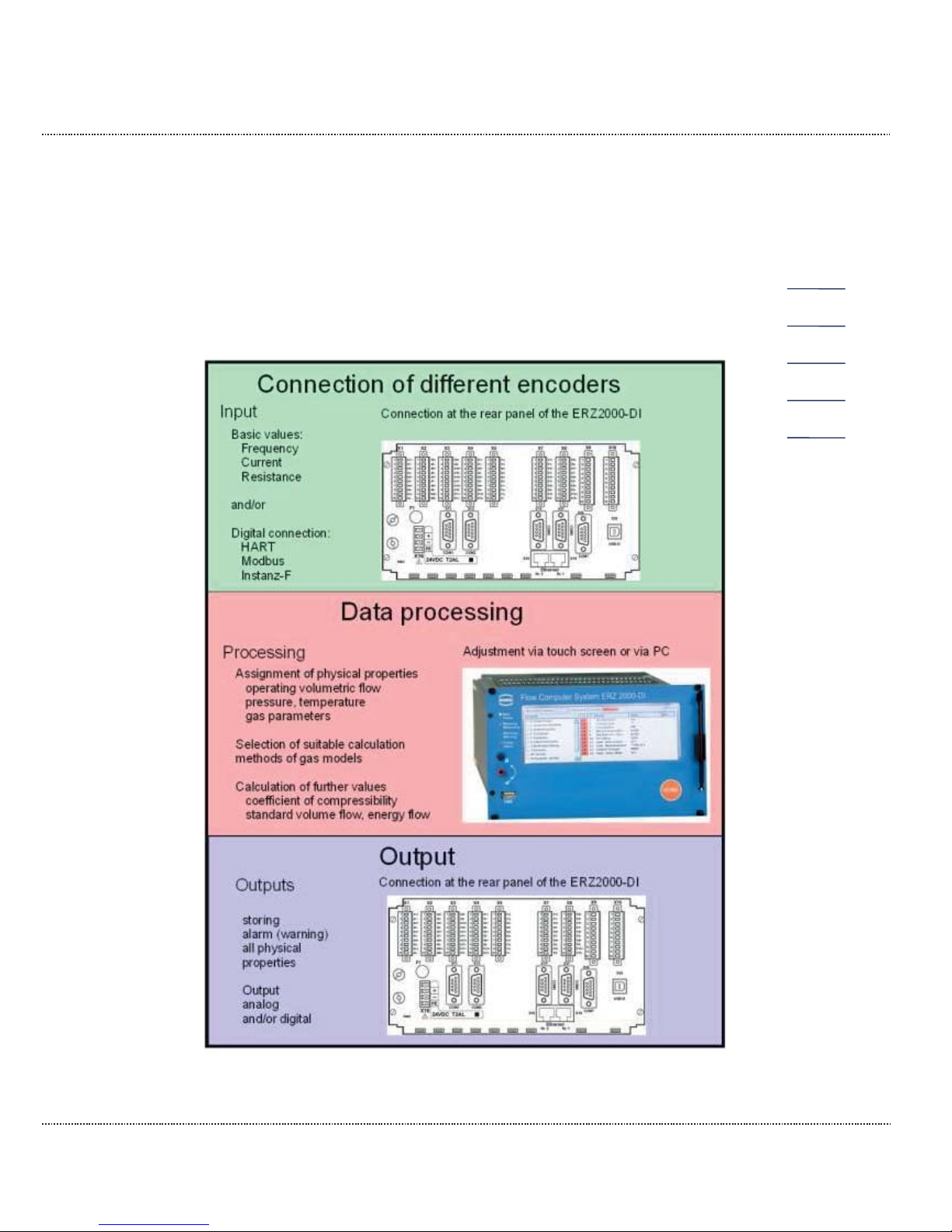
The flow computer ERZ2000-DI is designed to operate various sensors, particularly flow rate and gas analysis sensors, evaluate their signals or adopt and determine resulting operating and nominal volume flows. The resulting calculation variables can be represented in a graph and checked via alarm output, etc. The
ERZ2000-DI corresponds to the standards, directives and specifications listed in
chapter 1.5 Areas of application. Figure 1 explains the functional principle.
Figure 1: Functional principle
Page 20

1 ABOUT THIS MANUAL
Manual ERZ2000-DI · EN1.2 · 2017, December 21st
14
The ERZ2000-DI records analogue and digital values, such as frequencies, resistances, etc. Then these are assigned to physical variables, such as operating
volume flow or temperature. Further processing of these values takes place in the
ERZ2000-DI, where, for example, gas characteristics and standard volume flow
are calculated from these basic values. At the same time, a continuous check
guarantees that all necessary values are constantly available. An alarm or warning
message is triggered of adjustable limit values are exceeded or undercut.
The third task of the ERZ2000-DI is data storage and output, which can take place
in analogue and digital form. An alarm or a warning is also triggered if there is a
fault in the data recording.
1.4 Overview
The ERZ2000-DI, therefore, is an advancement of the ERZ2000 as a half 19"
slide-in module (half 19" width). Enhancements include a live browser (chapter 2.3
Browser home page and coordinate system) which enables permanent control of
the measurement data recording and reimbursement. A further enhancement is
the adjustment of the flow computer ERZ2000-DI and the parameterization of the
connected transmitters via a wizard on a PC. This wizard is not a separate PC program, and is executed directly in the browser.
The ERZ2000-DI system has a configuration consisting of 2 function groups. The
first function group provides the quick measurement recording, all inputs and outputs, all interfaces and manual operation via the front panel or via the wizard. The
internal calculations and converter functions are processed by the second assembly, the computing unit.
The working memory contains the variables, fields, buffers, etc. necessary for the
processing of the system software, as well as the (variable) device parameters of
all function assemblies. The device parameters are saved with a checksum that is
checked automatically each time the device is restarted.
The program memory contains the operating program of the device. A CRC checksum is calculated via the source and stored as a reference value. The correctness
of the checksum can be checked for the software ID in the coordinates of the
menu IE Software ID with the specifications on the type plate (chapter "2.7.3 Details" and chapter "2.7.4 Functions" – type plate).
Page 21
1 ABOUT THIS MANUAL
Manual ERZ2000-DI · EN1.2 · 2017, December 21st
15
1.5 Areas of application
The essential area of application is the recording and metering of flow rates
for custody transfer in natural gas flow measurement technology.
The device can be delivered in two different versions of the software, each with a
separate approval as:
x Status flow computer for natural gas (ERZ2004-DI)
x Calorific value flow computer for natural gas (ERZ2104-DI)
Both variants can access the following for the K coefficient calculation:
k = constant, ideal gas, GERG88 S set A, GERG 88 S set B,
GERG 88 S set C, AGA NX 19 L, AGA NX 19 H, AGA 8 Gross Meth. 1,
AGA 8 Gross Meth. 2, GOST 30319.2, AGA 8 (1985),
AGA 8 92DC + AGA 10, AGA 8 (2017), GERG 2004, GERG 2008,
AGA 8 92DC + ISO20765-1, GOST 8.662-2009, GOST 30319.3
The ERZ2000-DI diction is superordinate and applies for both variables in the following text.
The special factory setting and sealing (see chapter 1.5.2 Seal diagram for de-
vices with MID approval) is used for operation in custody transfer. In the process,
the function of the device must conform to the approval identified on the type plate.
Therefore, a subsequent modification of the device type is blocked.
Note
Modification of the device type is only possible under the supervision and
control of an officially recognized inspection authority or calibration official. Then the necessary seals are also applied after the modification.
1.5.1 Use in gas measurement technology
The ERZ2000-DI is not intended for use in explosion-prone areas. However, it can
operate sensors and other devices in explosion-prone areas.
Only operate the ERZ2000-DI in fault-free and complete condition.
If you make technical changes to the device, safe operation can no longer be
guaranteed.
Page 22
1 ABOUT THIS MANUAL
Manual ERZ2000-DI · EN1.2 · 2017, December 21st
16
Danger
x
Only use the ERZ2000-DI in its original condition.
x
When connecting sensors and other devices in explosion-
prone areas,
ensure that the appropriate explosion protection is provided for these
components. The specified maximum values in the certificates
issued
for these components must be observed.
x
They are intrinsically safe devices for which galvanic isolation must be
provided with connection of these devices.
x
Life-
threatening danger due to incorrect earthing. If the device is not
earthed correctly, so
that electrostatic charges can trigger the formation
of sparks, there is a risk of explosion.
Note
The ERZ2000-DI system is approved in different variants for custodytransfer application for gas measurement technology in Germany and
other countries.
The following EU type examination certificates are available for Germany
(see
Appendix Approvals:
ERZ2004
-DI MID Approval / Status flow computer
ERZ2104
-DI MessEV / Calorific value flow computer
ERZ2000-DI MessEV / Maximum load display and registering device
The respective applicable approval (approval symbol) is specified on the type plate
(chapter "2.7.4 Functions" – "Type plate"). The corresponding seal diagrams can
be found in this manual or the approval (chapter 1.5.2 Seal diagram).
If a pressure or temperature transmitter for the ERZ2004-DI or ERZ2104-DI types
approved in accordance with MID, it must be secured as follows:
− The main plate is provided with a sealing label.
− Access to the calibration switch, which is set to "write protect" during normal op-
eration, is secured by connecting the removable cover of the electronic housing
with sealing marks with the stationary parts of the housing.
Page 23
1 ABOUT THIS MANUAL
Manual ERZ2000-DI · EN1.2 · 2017, December 21st
17
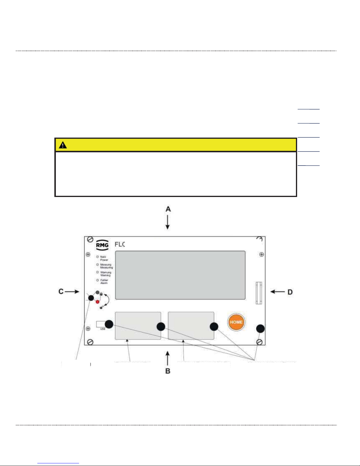
1.5.2 Seal diagram for devices with MID approval
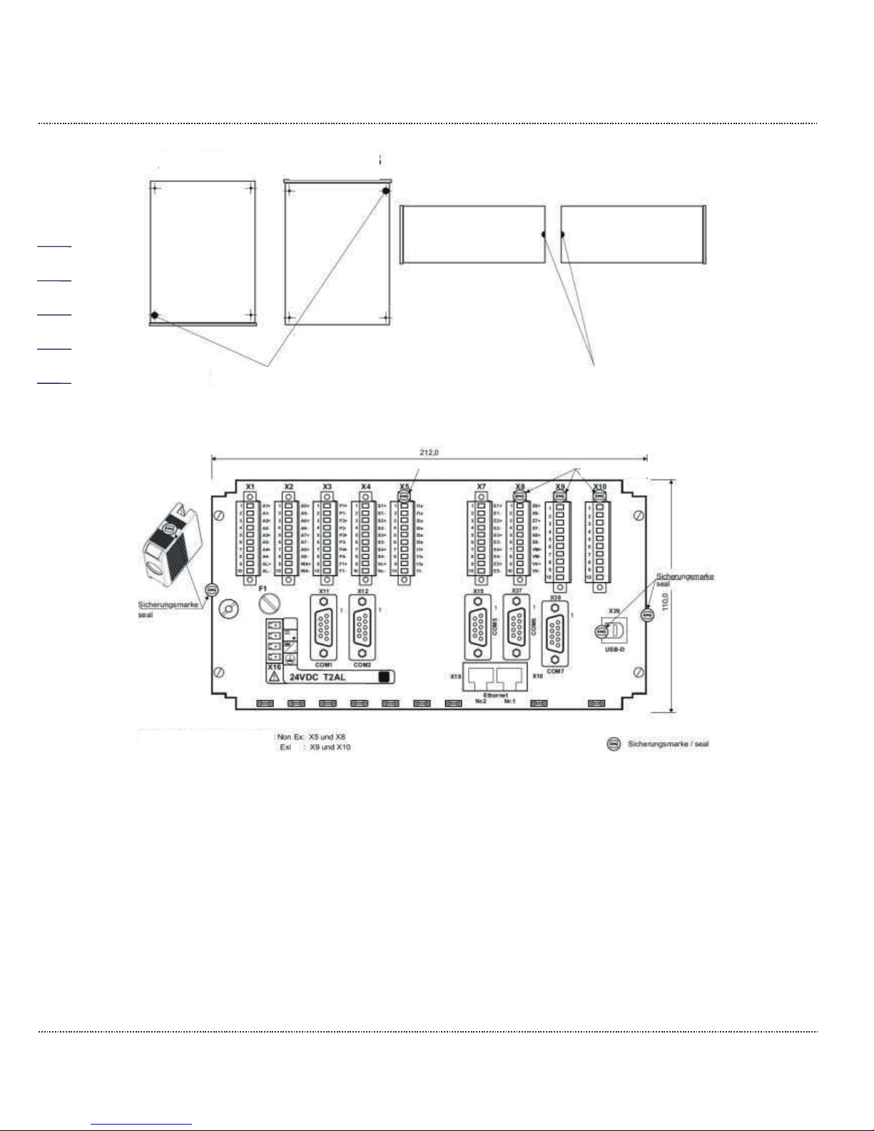
The ERZ2000-DI leaves the company with a setting agreed upon with the customer, which is protected from "significant" modifications by seals and metrological
sealing, or it leaves the factory without seals. In the latter case, a calibration official
must provide the device with seals according to the desired settings in accordance
with the seal diagram. The metrological seals must also be applied, as specified in
the seal diagram. Figure 2: Seal diagram - front and Figure 4: Seal diagram - rear
show the specified positions of the seals.
Caution
The ERZ2000-DI must only be used for custody transfer with unbroken
seal. Removal or damage to seals normally entails considerable expenses!
Re
-application of seals must only be carried out by an officially recog-
nized inspection authority or calibration o
fficials!
Figure 2: Seal diagram - front
FLOW COMPUTER SYSTEM ERZ 2000-DI
Type plate for:
ERZ2004
-DI/
ERZ2104-DI
Optional type plate
for maximum load
Metrological seal
Seal
Frontal view
Page 24
1 ABOUT THIS MANUAL
Manual ERZ2000-DI · EN1.2 · 2017, December 21st
18
Figure 3: Seal diagram - sides A, B, C, D
Figure 4: Seal diagram - rear
1.5.3 Signature, software and hardware data
The ERZ2000-DI offers the option of marking recorded data with an accompanying
signature. In doing so, the recipient receives the message and signature. They can
verify from the message and signature that the data is unchanged and originates
from a "secure" source, i.e. from a trustworthy sender or whether this is not the
case.
The signature is described in detail in the wizard (chapter 2.2 Adjustment of the
ERZ2000-DI via wizard).
View A
View B
View D
View C
Metrological seal
Metrological seal
Seal or sealing wire
Seal or sealing wire
Connector housing with seals:
a
a
Page 25
2 INTRODUCTION
Manual ERZ2000-DI · EN1.2 · 2017, December 21st
19
2 Introduction
2.1 Operation
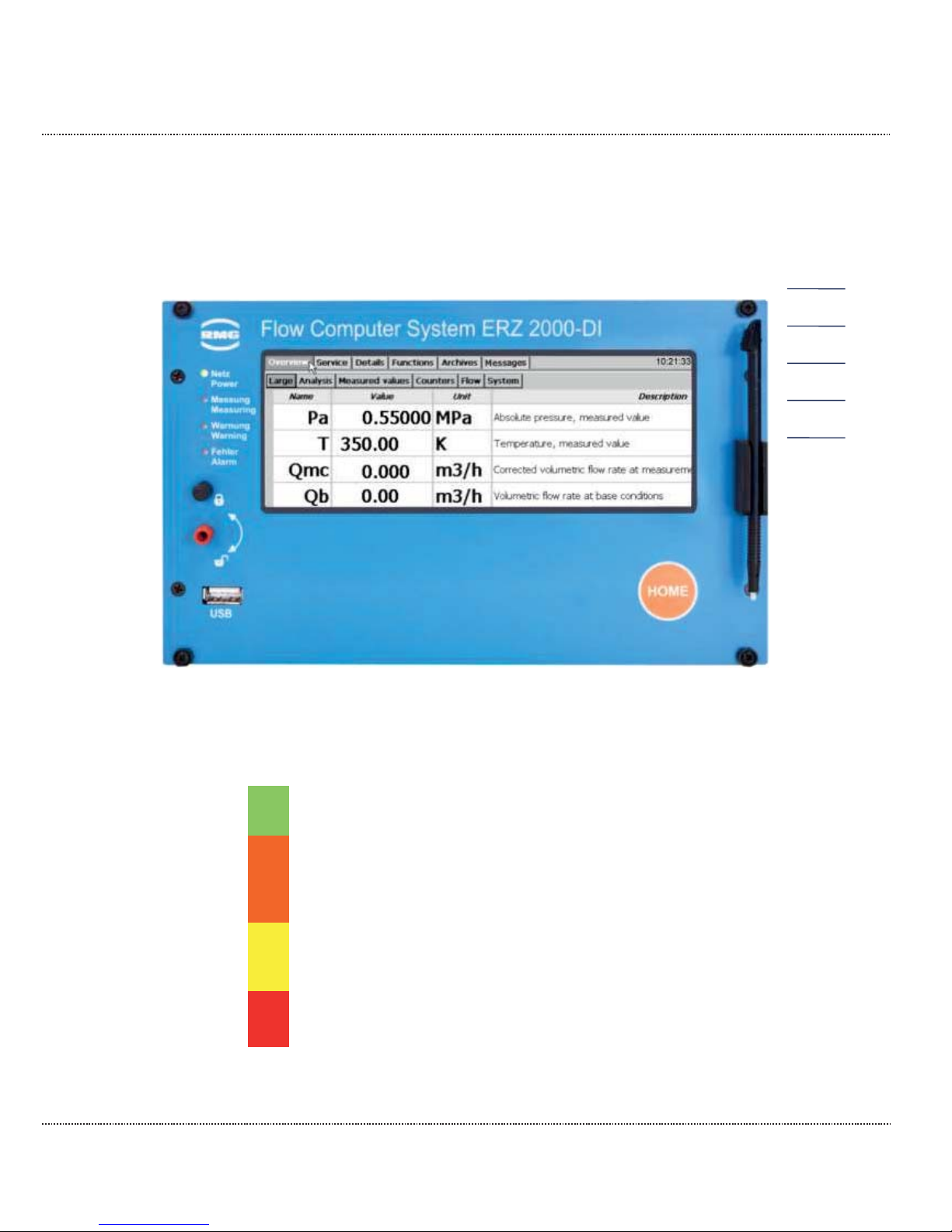
2.1.1 Front panel
Figure 5: Front panel
The following display and operating elements are located on the front panel:
Green LED
(Network)
Continuously illuminated
: Voltage indicator.
Blinking light
: User or calibration lock opened
Orange LED
(measurement)
Continuously illuminated
: Meter is connected and delivers
measurements.
Blinking light
:
Flow rate outside of permissible limits.
O
ff: No flow.
Yellow LED
(warning)
Blinking light
: There is currently a fault
(warning) in
non-custody-transfer functions
Continuously
illuminated: A warning is pending
Red LED
(error)
Blinking light: There is currently a fault in
custody-transfer functions (alarm)
Continuously illuminated: An alarm is pending
Page 26
2 INTRODUCTION
Manual ERZ2000-DI · EN1.2 · 2017, December 21st
20
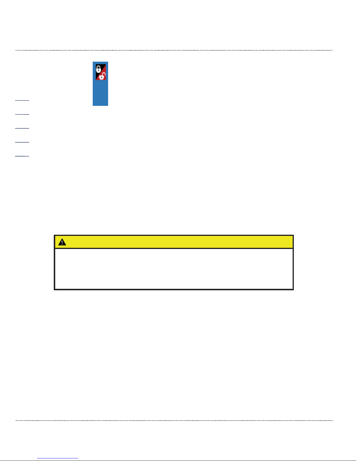
Custody
transfer
switch
Sealable rotary switch,
when the limit stop in the clockwise direction is
reached, the custody transfer lock is open,
when the limit stop in the counterclockwise direction is
reached, the custody transfer lock is closed
USB interface
For connection of USB components (e.g. a mouse), this interface is sealed in custody transfer mode and cannot be used.
Home button
To jump to the startup/message screen (alternating)
Touch screen
Display and control panel.
2.1.2 Operation on the touch screen
The touch screen enables operation via a graphic and largely self-explanatory
user interface. You jump back to the home screen from any place in the menu with
the "home" button. Pressing the button again jumps to the "Message"
screen/menu.
Caution
Operate the touch screen directly with your finger or use the supplied
plastic stylus.
Never use hard or sharp objects such as screwdrivers or pens (otherwise,
there is a risk that
the foil of the touch screen is scratched or torn).
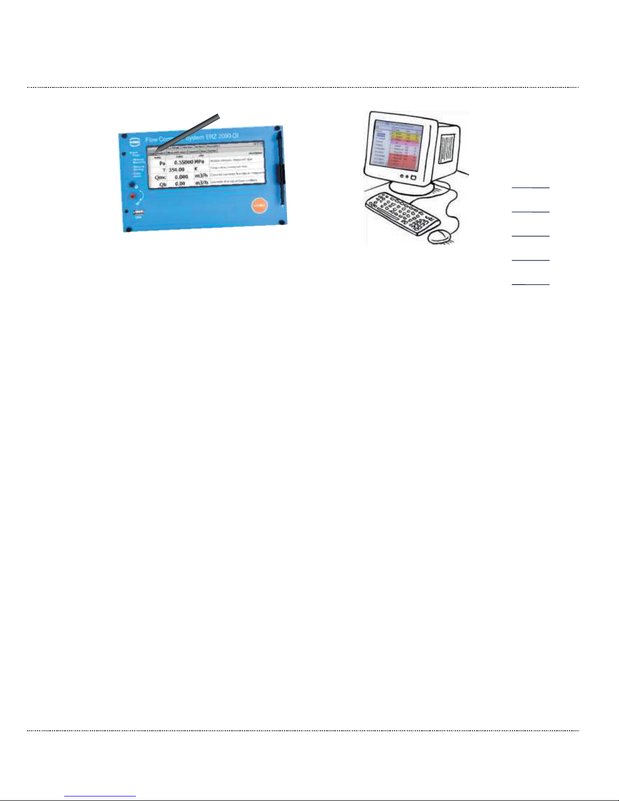
2.1.3 Remote control / parameterization
In addition to operation via the front panel, the touchscreen provides an additional
convenient option to operate or parameterize the device either locally or remotely
with a PC or notebook.
Page 27
2 INTRODUCTION
Manual ERZ2000-DI · EN1.2 · 2017, December 21st
21
Figure 6: Operation of the ERZ2000-DI
Very simple adjustment takes place with the browser available on the PC (e.g. Internet Explorer, Firefox, etc.), which essentially corresponds to operation of the
touchscreen. In addition, display on the PC enables the startup of a wizard directly
in the browser for convenient commissioning. The local connection is established
via a standard network cable (LAN cable).
Operation of the ERZ2000-DI via the browser is the recommended adjustment and
operation possibility and, therefore, is given priority below. Operation with the
browser generally offers expanded display options. Furthermore, display on the
touchscreen is identical to display on the browser; small differences are purely visual in nature and do not limit the adjustment options for the ERZ2000-DI via the
web browser.
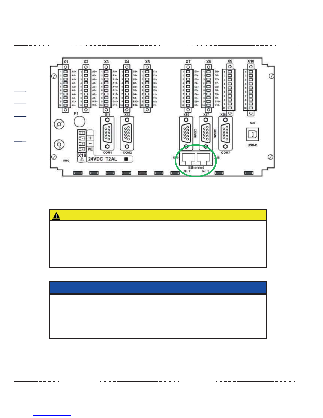
The LAN cable connects one of the 2 connection ports (Ethernet 1 or 2) on the rear
side of the ERZ2000-DI (see Figure 7: Rear side of the ERZ2000-DI and Ethernet
interfaces) with the local network of the PC.
Page 28
2 INTRODUCTION
Manual ERZ2000-DI · EN1.2 · 2017, December 21st
22
Figure 7: Rear side of the ERZ2000-DI and Ethernet interfaces
Caution
Then the ERZ2000-DI can only be integrated into an existing network if the
network permits integration of third
-party devices.
Protected company networks may prohibit this access.
Contact your IT department to discuss how you can integrate the
ERZ2000
-DI into your company network.
Note
The ERZ2000
-D has – as shown in Figure 7: Rear side of the ERZ2000-
DI
and
Ethernet interfaces –
two Ethernet interfaces. Two separate accesses
are also possible via these interfaces. With simultaneous use of the
ERZ2000
-DI by two users, no
connection (bridge) is established between
th
e (normally) two different networks.
In order to ensure that the network connections functions correctly, the correct
TCP/IP address of the ERZ2000-DI must be entered in the browser. This TCP/IP
Page 29
2 INTRODUCTION
Manual ERZ2000-DI · EN1.2 · 2017, December 21st
23
address can be read on the ERZ2000-DI. For this purpose, proceed as follows after
starting up the device:
Select the following with the stylus:
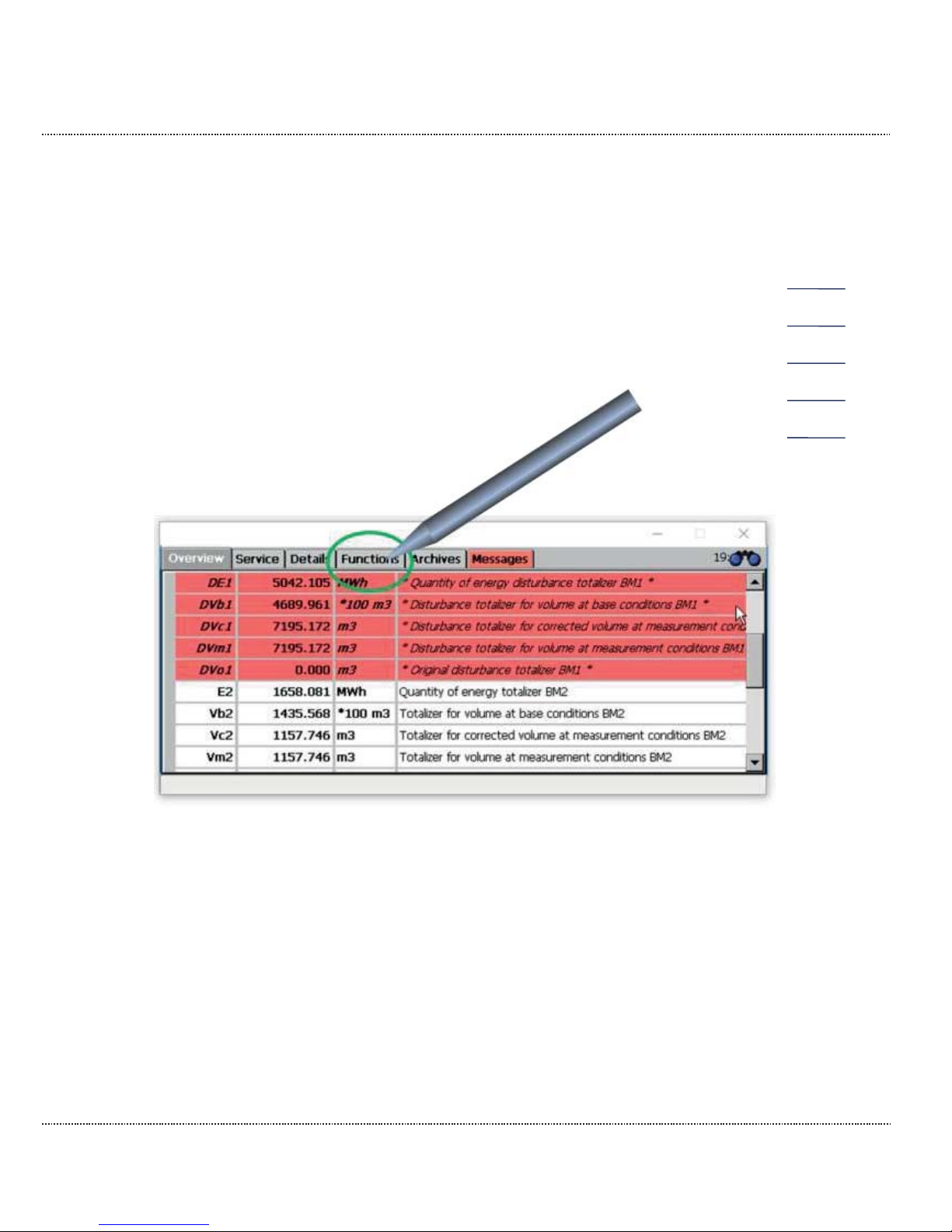
1. The ERZ2000-DI logs in after start-up with the following screen. Select the
"Functions" tab in the upper part of the display.
Figure 8: ERZ2000-DI Start page
Page 30
2 INTRODUCTION
Manual ERZ2000-DI · EN1.2 · 2017, December 21st
24
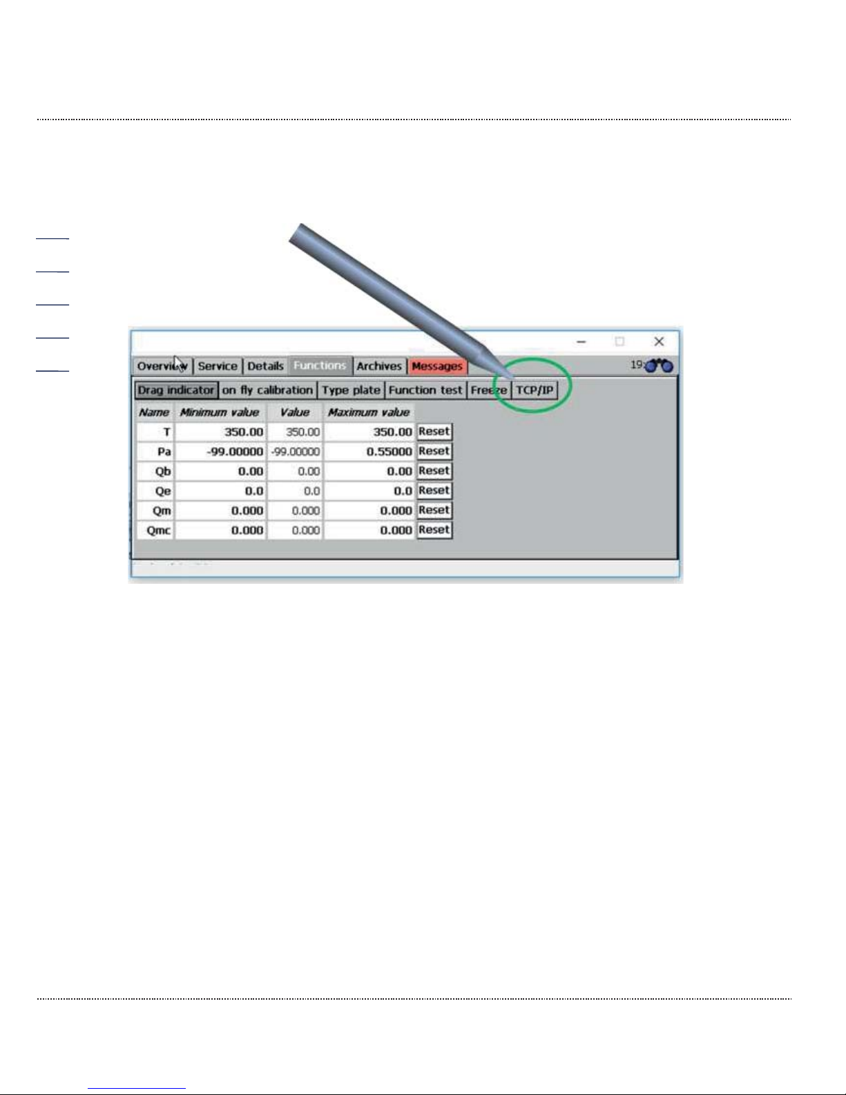
2. Then select the TCP/IP tab.
Figure 9: Functions menu
Page 31
2 INTRODUCTION
Manual ERZ2000-DI · EN1.2 · 2017, December 21st
25
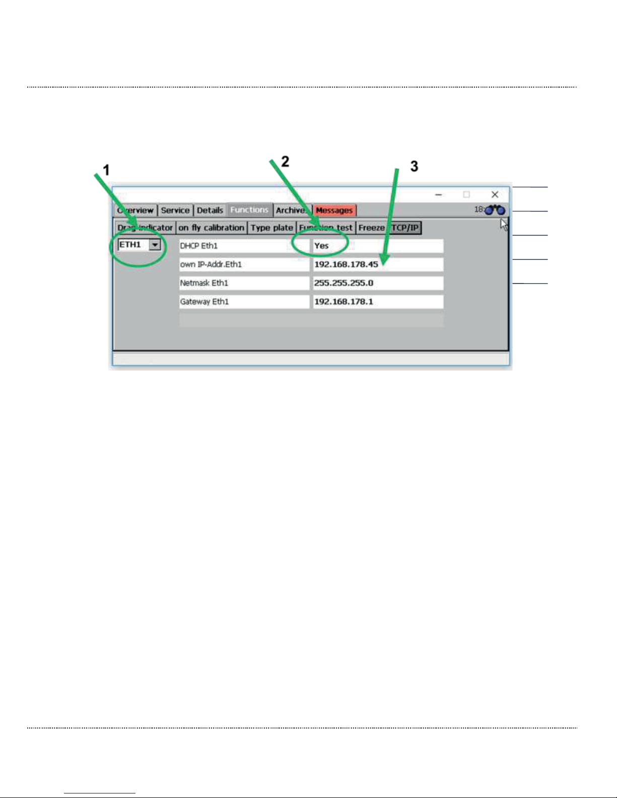
3. After activation, the screen below appears.
Figure 10: TCP/IP menu
1 Check whether you are working with interface 1 (ETH1) or 2 (ETH2)
and adjust this setting in the selection menu (please activate) accordingly.
2 Check the DHCP setting of the interface.
If a DHCP server is available in the network, the IP address is assigned automatically when "yes" is activated. When the setting is
"no", the IP address must be entered manually.
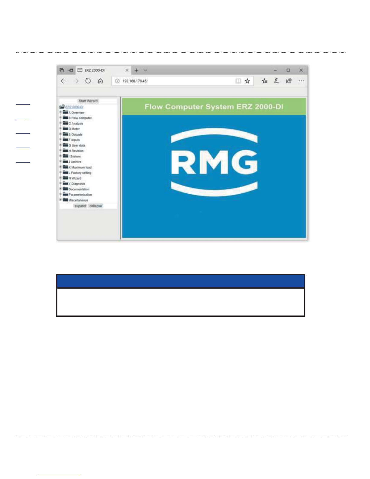
3 Normally, you should be able to see the IP address now.
If the TCP/IP address in the browser is entered, the following home page of the
ERZ2000-DI appears.
Page 32
2 INTRODUCTION
Manual ERZ2000-DI · EN1.2 · 2017, December 21st
26
Figure 11: Home page after entry of the TCP/IP address
Note
If you work with Microsoft Internet Explorer – before the wizard can be
started for simplified operation
– the compatibility status of the web
browser must be checked and adjusted as necessary.
If you are using Microsoft Internet Explorer, the compatibility view can be adjusted
under "Extras" in the web browser. In this menu you may find the submenu “Ad-
justment of the compatibility view”. The field “Show intranet sites in compatibility
view” must be activated in this menu.
Page 33
2 INTRODUCTION
Manual ERZ2000-DI · EN1.2 · 2017, December 21st
27
2.1.4 Operation on the home page
The home page can be operated with a mouse and keyboard in the accustomed
manner. Operations are equivalent to those on the touchscreen of the
ERZ2000-DI and are adopted accordingly. For instance, the TCP/IP addresses
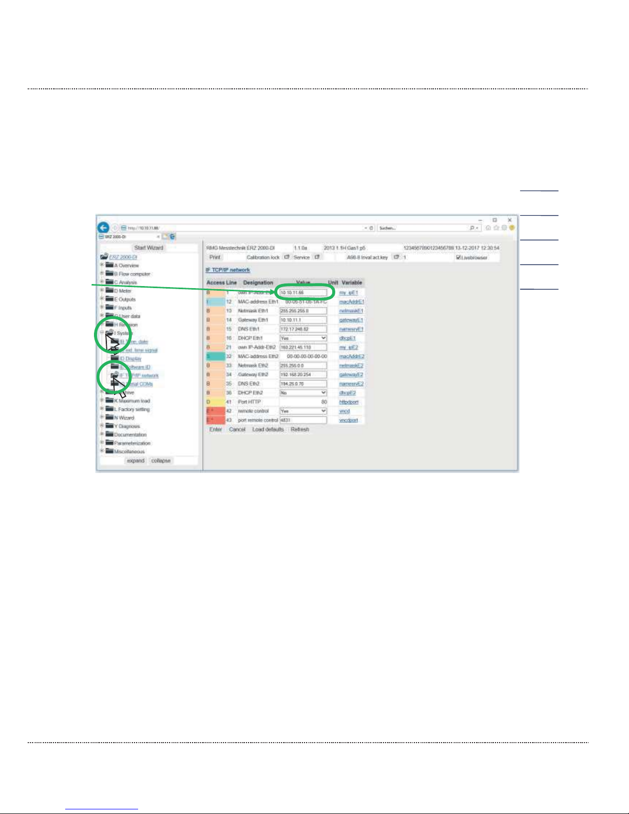
can be queried here. The IP address is displayed in the "Details" menus in
Figure 12: IF TCP/IP network menu.
Figure 12: IF TCP/IP network menu
1. Activate the menu I System on the home page with the mouse
2. Activate the menu IF TCP/IP network with the mouse
3. The TCP/IP address can be read in the field with the green frame
3
2
1
Page 34
2 INTRODUCTION
Manual ERZ2000-DI · EN1.2 · 2017, December 21st
28
2.2 Adjustment of the ERZ2000-DI via wizard
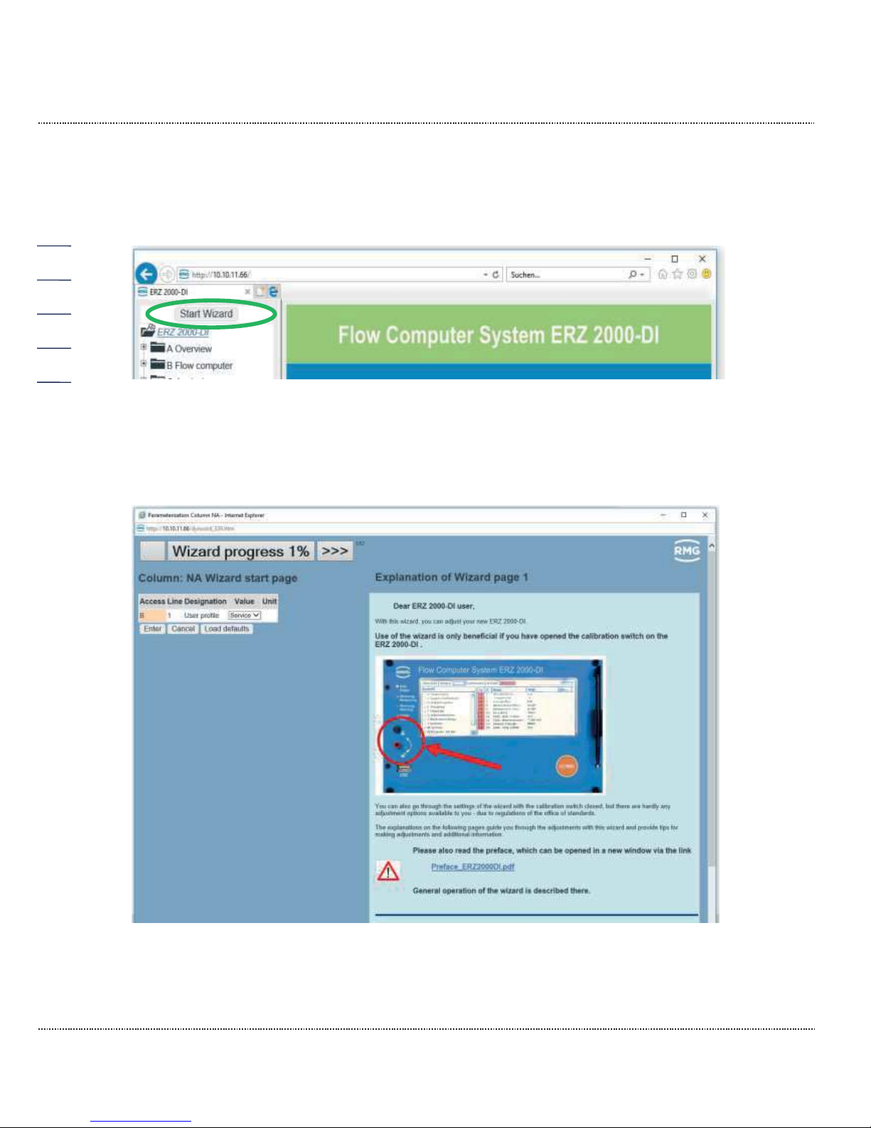
Adjustment of the ERZ2000-DI preferably takes place using a wizard. For this purpose, it must be activated on the home page:
Figure 13: Starting the wizard
After activation of the "Start wizard" field circled in green, the settings tool of the
ERZ2000-DI appears.
Figure 14: Wizard home page
Page 35
2 INTRODUCTION
Manual ERZ2000-DI · EN1.2 · 2017, December 21st
29
The wizard is a component of the ERZ2000-DI and stored internally. This also applies for all documents and images integrated in the wizard. They are not listed here
again. The wizard and all integrated documents and images, therefore, are an essential part of the documentation.
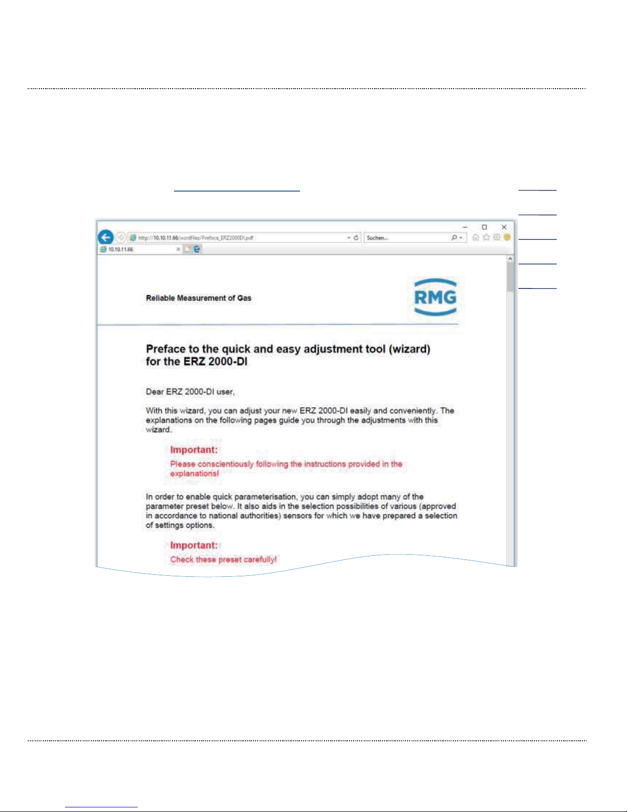
The document: Preface_ERZ2000DI.pdf is integrated on the first wizard screen, and
can be opened by clicking on the left part of this home page.
Figure 15: Preface to the wizard
This preface provides general information for use of the wizard and should absolutely be read prior to making any further settings in the wizard, which is why it is
marked with an Attention symbol. This information is also helpful for a better understanding and use of the remainder of the manual.
The home page requires 2 essential settings. Firstly, access authorization must be
specified (see chapter 2.4 Access protection for data and settings).
Page 36
2 INTRODUCTION
Manual ERZ2000-DI · EN1.2 · 2017, December 21st
30
Caution
Simplified adjustment with the wizard is basically only possible with an
open calibration switch of
the ERZ2000-DI.
However, the notice on
removal of seals (chapter 1.5.2 Seal diagram for
devices with MID approval
) must be observed!
If the calibration switch is closed - for legal custody-transfer purposes - almost no
settings are possible on the wizard screens.
Secondly, the user profile must be specified. "User" should be selected for as an
"ordinary" user of the flow computer; "Service" can also be selected for internal
settings.
All settings options that are necessary for parameterization are available to a
"User". Then the simplified adjustment of the ERZ2000-DI with the help of the wizard is also enabled.
Note
Recommendation:
Please choose
User as a user profile!
The wizard (and the ERZ2000-DI) displays only the parameters that are relevant according to the intended use for the
selected device type. Com-
plete settings menus and/or individual parameters are hidden (in the wizard and coordinate system of the ERZ2000
-DI).
The wizard should be used in the specified sequence. In this case, unnecessary additional settings options are hidden on the subsequent pages after settings have been changed. If, for instance, the GERG 88 S is selected
for state equation of the gas composition, only the relevant input values
for this calculation are required as entries. Portions of gas components
such as methane or other types are no longer displayed or queried.
Scrolling past, forwards or backwards can result in unnecessary entries or
corrections if these settings have not been carried out (yet).
The settings that are initiated with the recommendation button are also
made on the basis of entries which were already made
–
then they are only
permitted/logical if the sequence has been observed.
Page 37

2 INTRODUCTION
Manual ERZ2000-DI · EN1.2 · 2017, December 21st
31
The "Service” setting always shows all settings menus and settings possibilities,
regardless of settings already made by the user. These settings options can be edited on the following wizard screens in the "Service" setting, although they are entirely unnecessary for the overall settings of the ERZ2000-DI.
Refer to the wizard for all additional settings here. The selection of all permissible
transmitters that can normally be integrated easily with a pre-assignment of all relevant parameters by clicking the mouse.
Page 38
2 INTRODUCTION
Manual ERZ2000-DI · EN1.2 · 2017, December 21st
32
2.3 Browser home page and coordinate system
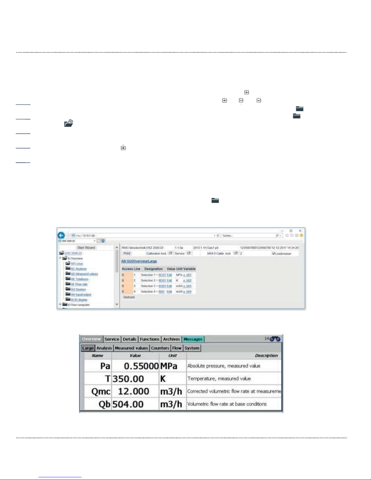
Links in the home page there is a tree structure that is comparable to Windows Explorer. The relevant menu is opened by clicking on one of the : measurements,
components, ... In the process, a symbol change from to or (bottom
menu item) takes place and various sub-menus can be selected by clicking on ,
such as overviews, reassessment, gas properties, etc. A symbol change from
to also takes place here. Then you see the content of the selected menu, see
Figure 16: "Overviews .
Click on the first, top , then the menu "A Overview" in which various sub-items are
listed in the menu tree appears.
2.3.1 Large representation in the display
The first sub-item "AB Large" ("Click" on the top ) permits the selection of 4
parameters, which are displayed in a large font on the display of the ERZ2000-DI
for better reading at some distance (see Figure 17: Display view)
Figure 16: "Overviews " menu
Figure 17: Display view
,
Page 39
2 INTRODUCTION
Manual ERZ2000-DI · EN1.2 · 2017, December 21st
33
This representation can be activated in the display of the ERZ2000-DI on the
touchscreen:
1. Activation of the "Overview" tab
2. Activation of the "Large" tab
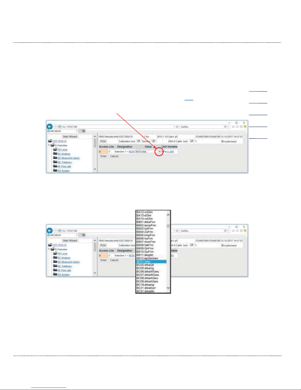
The displayed parameters can be changed by activating edit after the relevant selection. Then you have an additional selection with which the value can be
changed if you click on the
arrow.
Figure 18: Selection of the large representation of parameters
Then a selection appears as shown in Figure 19: Selection of parameters.
Figure 19: Selection of parameters
Any other parameters can be selected here, "entered" and then confirmed with
"continue".
16
Page 40
2 INTRODUCTION
Manual ERZ2000-DI · EN1.2 · 2017, December 21st
34
For assignment of the parameter to the selected value can be accessed by clicking on the term after the selection (BC01 in this case). The coordinate BC01 Absolute pressure is recognizable. This menu can also be reached with selection of the
menu B Reassessment and then BC Absolute pressure is activated on the start
screen. The coordinate BC01 Absolute pressure is in the 1st line.
2.3.2 Further specifications in the home page
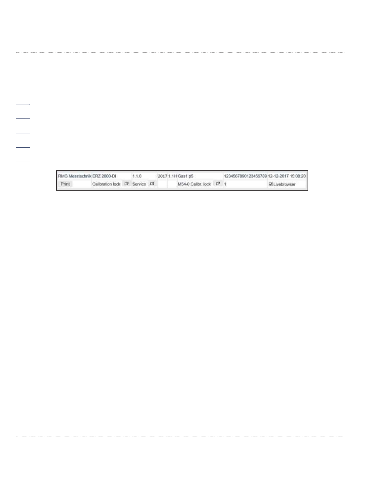
In the right-hand window, the following can also be seen in the upper lines (Figure
20: Top lines in the menu):
Figure 20: Top lines in the menu
Top line:
1. RMG Messtechnik
2. ERZ2000-DI
3. 1.1.0 Firmware version
4. 2017 Year of manufacture of the ERZ2000-DI
5. 1.1H Rail name EL 2
6. Gas1 p5 Measurement point EL 3
7. 1234567890123456789
8. 12-12-2017 Current date
9. 15:08:20 Current time
Page 41
2 INTRODUCTION
Manual ERZ2000-DI · EN1.2 · 2017, December 21st
35
Note
If the live browser is activated (see below);
For field 9: Time
The time must change in the seconds!
A live connection is only provided thereafter.
All
values, not only the values shown in Figure 16: "Overviews " menu
are
updated "online" (continuously
- live).
If the time does not change in seconds, there is no or only a poor connection between the ERZ2000
-
DI and the PC. It may also be due to an "old"
browser or the settings above have not been carried out.
A poor connection can impede or completely block data transmission (e.g.
the reading of archives).
Second line:
1. Print The framed area shows an operable field; the
displayed page is printed.
2. Calibration lock / locked Shows the current access here: "Calibration lock
open"
The menu GA Access rights can be opened by
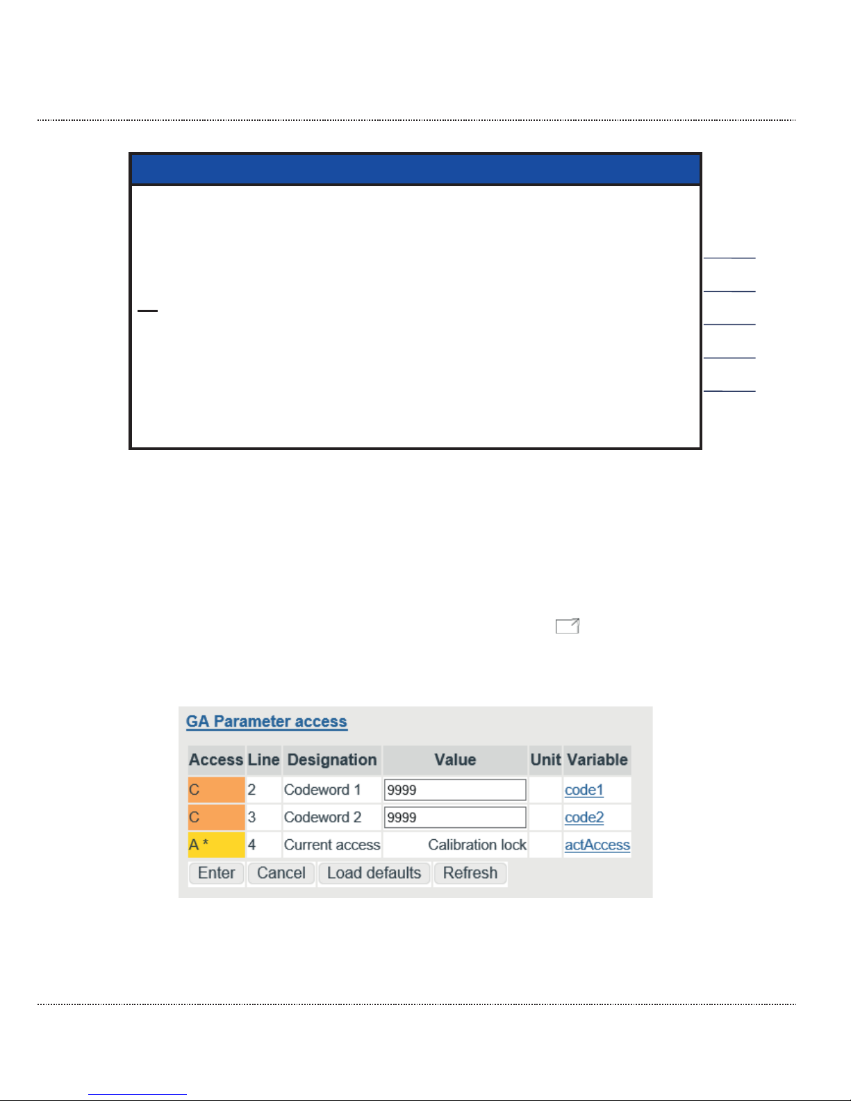
clicking in the adjacent field . The code values are visible and can be changed with the calibration switch open
Figure 21: Access to the device
(For more information, see Chapter 2.4 Access protection for data and settings)
Page 42
2 INTRODUCTION
Manual ERZ2000-DI · EN1.2 · 2017, December 21st
36
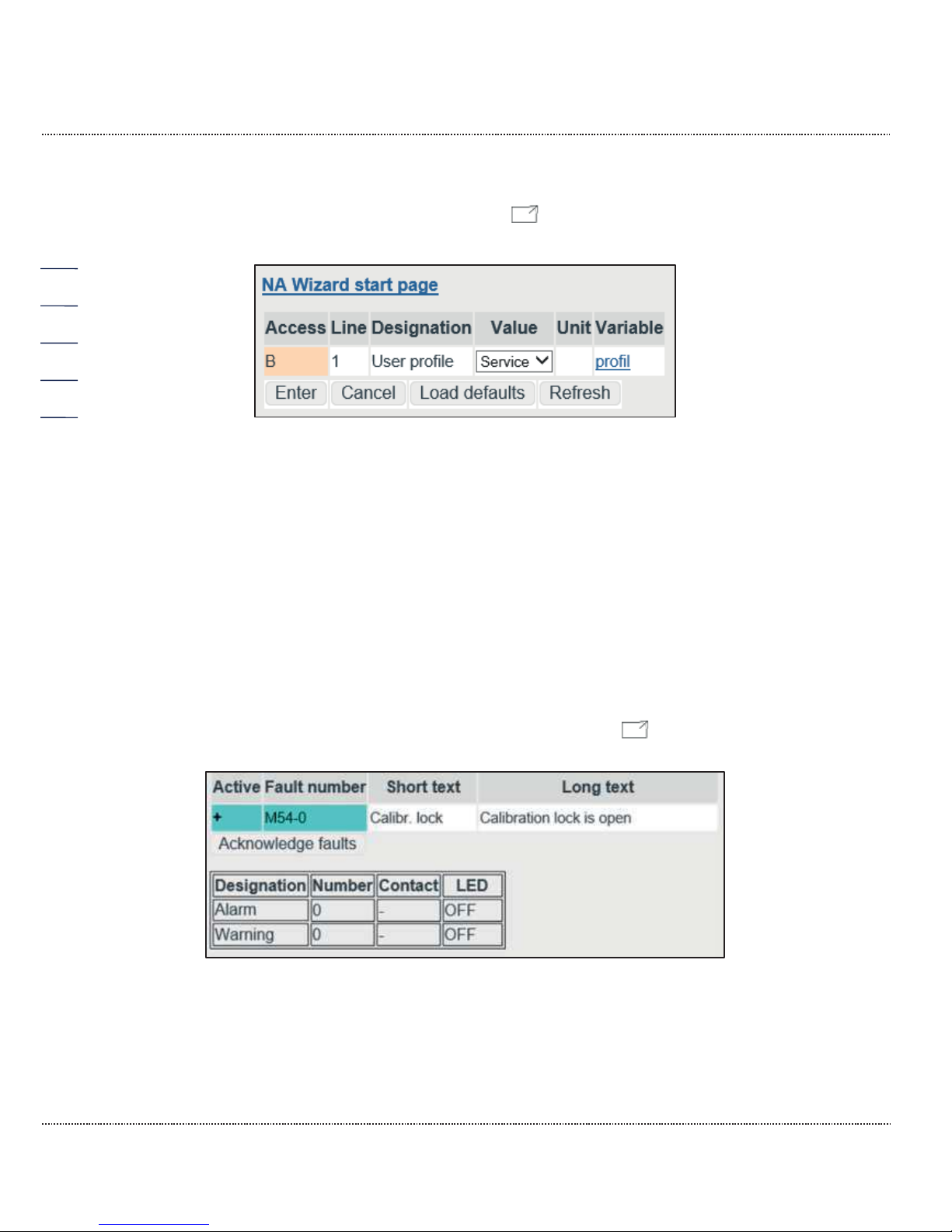
3. Service Shows the user profile. The menu NA Wizard
home page can be opened by clicking in the
adjacent field .
Figure 22: User profile
(For more information, see wizard)
4. " "
5. " "
6. Error display Pending errors are continuously displayed here.
Here: "M54 Calibration lock"
(= Calibration lock is open)
All available messages can be displayed by
clicking in the adjacent field .
Figure 23: Error messages
7. 1 Debug value (internal use)
8. " "
Page 43
2 INTRODUCTION
Manual ERZ2000-DI · EN1.2 · 2017, December 21st
37
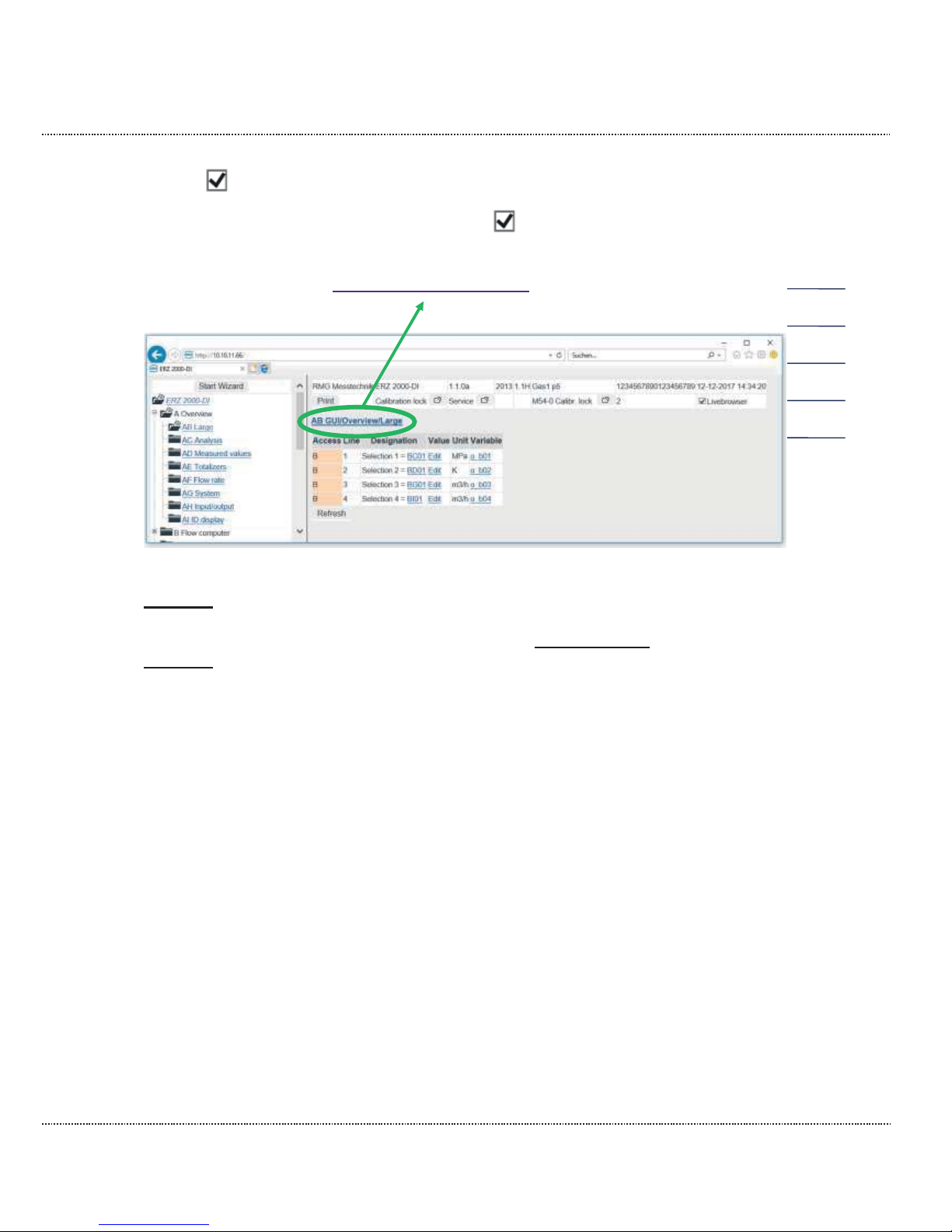
9. Live browser The live browser is activated and all data (such
as time) is updated continuously.
Clicking on deactivates the live browser ().
Furthermore, a heading AB GUI/Overview/Large is shown in Figure 16: "Over-
views " menu:
The selected measurements or parameters are displayed there. Click on this
Heading, then a menu with further explanations for the values on the previous
screen appears. Windows in which additional, in-depth information of the selected
parameter is shown are opened by clicking on the underlined text. Clicking on the
Heading again will bring you back to the initial menu (Figure 16: "Overviews ).
Page 44
2 INTRODUCTION
Manual ERZ2000-DI · EN1.2 · 2017, December 21st
38
The representation of measurements and parameters is shown in other menus.
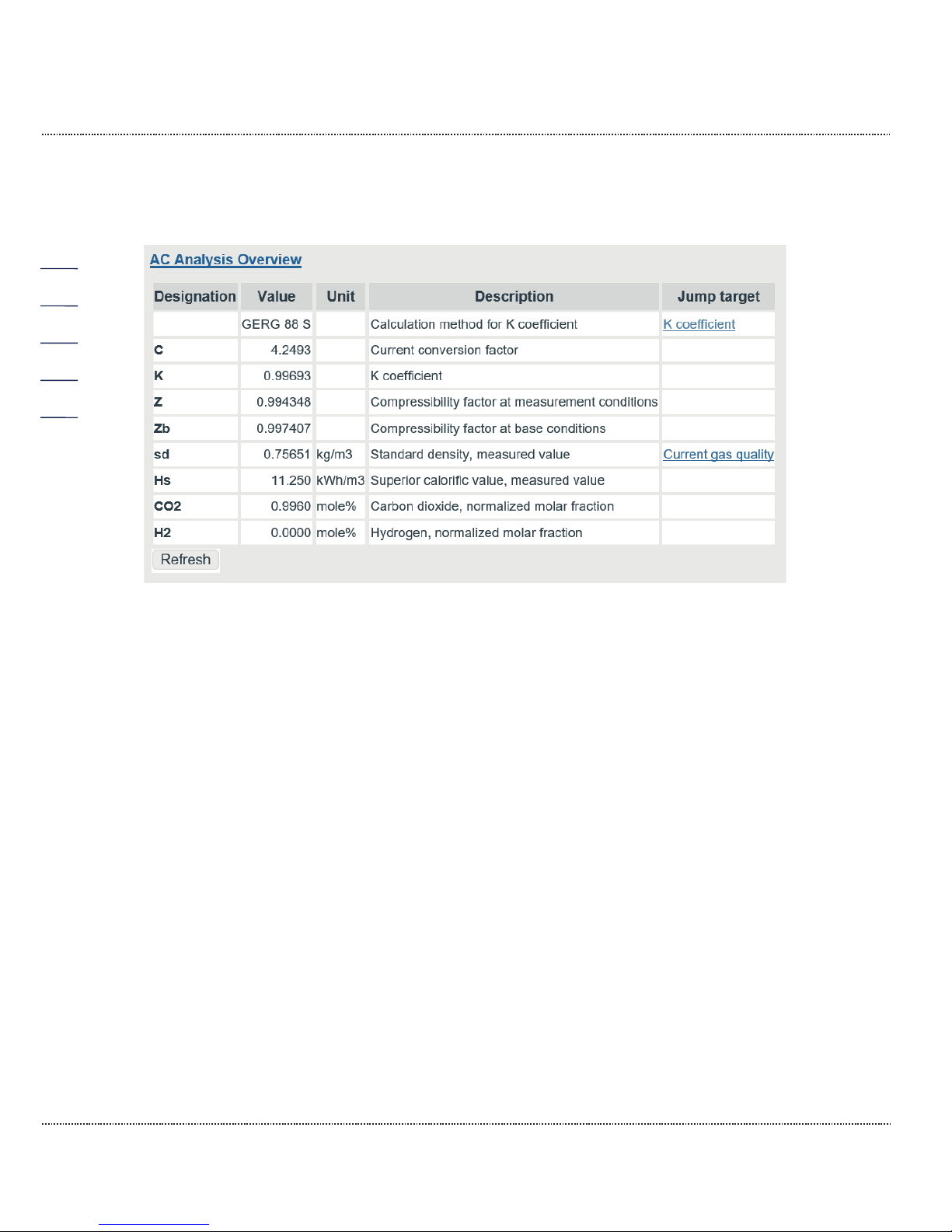
For example, various analytical values are specified in the next menu
AC Analysis Overview.
Figure 24: "AC Analysis Overview " menu
The parameters contain the corresponding live values with a unit (if available) and
the jump target that describes the determination and specification of the respective
value in a menu. By clicking on the parameter under the jump target, the corresponding menu appears; e.g. clicking on the K coefficient opens the sub-menu
"BH Calculation of K (compressibility) coefficient".
Page 45
2 INTRODUCTION
Manual ERZ2000-DI · EN1.2 · 2017, December 21st
39
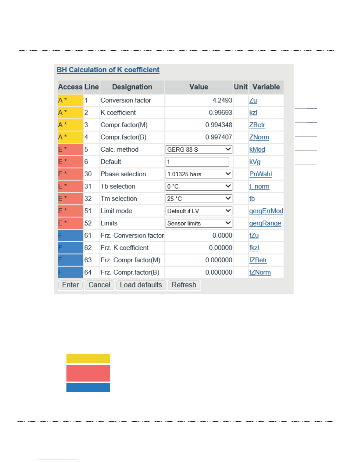
Figure 25: "BH Calculation of K coefficient"
The parameters on the right side belong to different categories, which is indicated
with different colors, identification letters and other symbols in the left part on the
right screen in the relevant line. The most important include:
A
Dark yellow
Display values, change not possible
E
Red
Custody transfer parameter, can be changed with open calibration switch
F
Blue
Freeze parameter
This identification and the color assignment are shown in detail in Chapter 2.3.3
Display.
Page 46
2 INTRODUCTION
Manual ERZ2000-DI · EN1.2 · 2017, December 21st
40
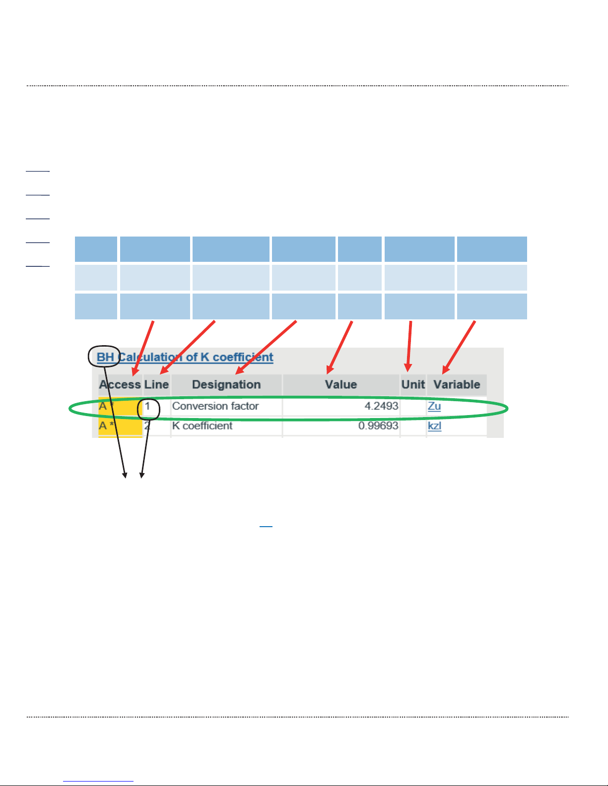
All measurements, calculation values, parameters and functions are arranged in a
coordinate system. There are several tables with columns and lines in this coordinate system. Each table as a (umbrella) term, or a heading, under which all various
points which have a logical connection with the term are summarized line by line;
for example, points such as BH05 Calc. method, BH06 Default, etc. are summarized under the term BH Calculation of K coefficient. These "points" are referred
to as "coordinates" below. These individual coordinates are assigned additional
meanings column-by-column:
Column
1.
2.
3.
4.
5.
6.
Access
column
Line
number
Identification
Alpha-num.
Identification
Numerical
identification
Coordinate
name
Value
Corresponding unit
Variable
Figure 26: Coordinate system
With BH01 Conversion factor, the coordinate is uniquely identified in the green
frame. The "Variable" column is only visible in Developer mode (see Chapter 2.4
Access protection for data and settings), for which the highest access level is re-
quired. The variable identification Zu establishes a unique identification for the
physical variable; this physical identification is assigned to the coordinate BH01
Conversion factor.
If applicable, a coordinate can also be a function, then these designations can also
appear simultaneously.
The coordinates are arranged in a table, a coordinate system in the form of a matrix, in which each column (also identified with menu) is identified with two letters
and each line is identified with a number. Furthermore, columns that belong together are summarized in groups and each group has the same first letters, e.g.
"A" for the measurement columns. Each table as a (umbrella) term, or a heading,
under which all various points which have a logical connection with the term are
summarized line by line; for example, points such as "status coefficient", "calculation type", etc. are summarized under the term "calculation of the compressibility
Page 47
2 INTRODUCTION
Manual ERZ2000-DI · EN1.2 · 2017, December 21st
41
number". Chapters belonging together are summarized under the first letters: AA,
AB, AC, AD... / BA, BB, BC, ... / CA, CB, CC, CD.....
Note
The method of counting takes place with letter / number combinations beginning with
AA = first column
01
= first line
Chapters belonging together are summarized under the first letters: AA,
AB, AC, AD... / BA, BB, BC, ... / CA, CB, CC, CD ...
Only the values that are relevant for the selected device type are displayed. Therefore, complete columns and/or individual coordinates are
hidden in the coordinate system
–
depending on the device type and oper-
ating mode setting.
In addition, there are coordinates (functions) that are intended for service
purposes and for review
, only. Depending on the user profile and the
de-
vice type, therefore, all parameters and data are not always visible.
The columns displayed to the left and the parameters and measurements
displayed to the right depend on the selected user profile. All data is displayed in "Service" mode only; the device is delivered in "User" mode.
2.3.3 Display
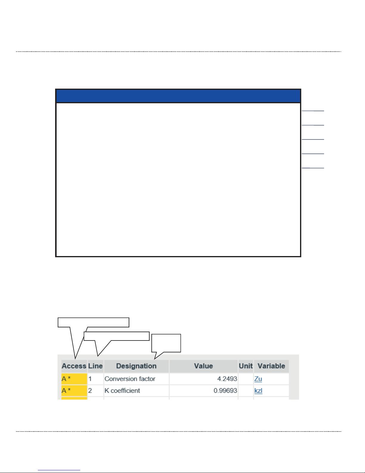
The visibility of coordinates and columns depends on the user profile setting. All
coordinates are only visible in the service setting. Example display:
Figure 27: Parameter display
Access authorization
Coordinate system
Display
text
Page 48
2 INTRODUCTION
Manual ERZ2000-DI · EN1.2 · 2017, December 21st
42
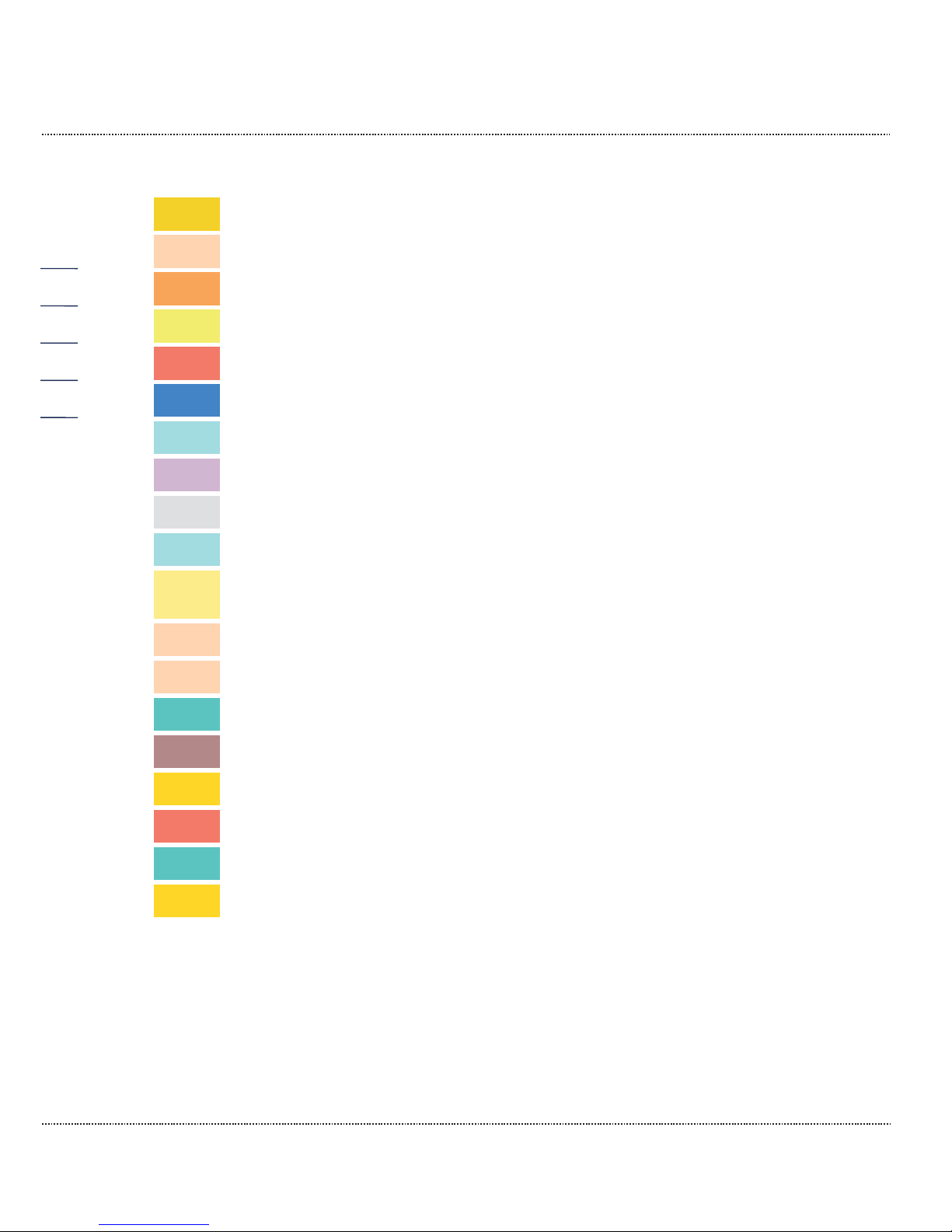
Explanation of symbols in the Access column:
A
Display values, custody transfer, change not possible
B
Parameter under single code word protection
C
Special case: Code word entry/check
D
General displays, display values, non-custody-transfer
E
Parameters protected by official calibration
F
Freeze value, not editable
I
Interface variable – measurement, not editable
J
Interface variable – imported type plate (e.g. hard), not editable
K
Constant, not editable
M
Imported measurement via Modbus, not editable
N
Non-custody-transfer meters, CO2, all disturbance meters, meters
with an undefined billing mode, customer meters
P
Automatically changing input value with simple code word protection
Q
Automatically changing input value without protection
S
Parameter under super user protection
T
Parameter under double code word protection
W
Factory parameter, can only be changed in the factory
X
Automatically changing input value under calibration switch
Y
Automatically changing input value under super user protection
Z
Custody transfer meters Vo, Vm, Vb, E, M
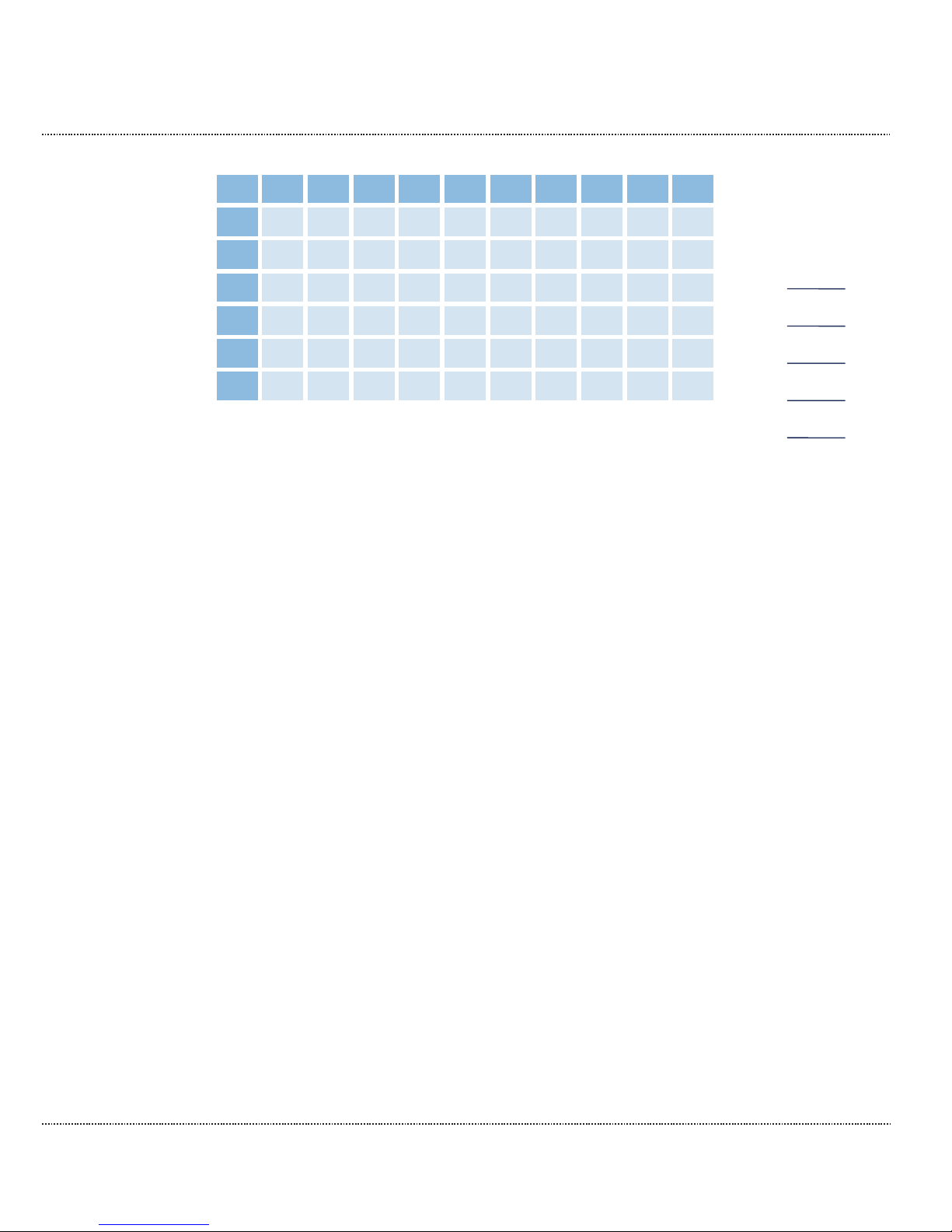
The coordinate system runs horizontally from AA to QX (columns) and vertically
from 1 to 99 (lines) (Table 1: Coordinate system)
Page 49
2 INTRODUCTION
Manual ERZ2000-DI · EN1.2 · 2017, December 21st
43
AA
AB
AC
...
BA
BC
...
...
...
QW
QX
01
02
..
..
98
99
Table 1: Coordinate system
Displayed parameters
Parameters
These behave like constants. Editing changes the value of the respective constant.
Automatically changing values that can be edited
These values behave like changing values. Editing will change the initial value of
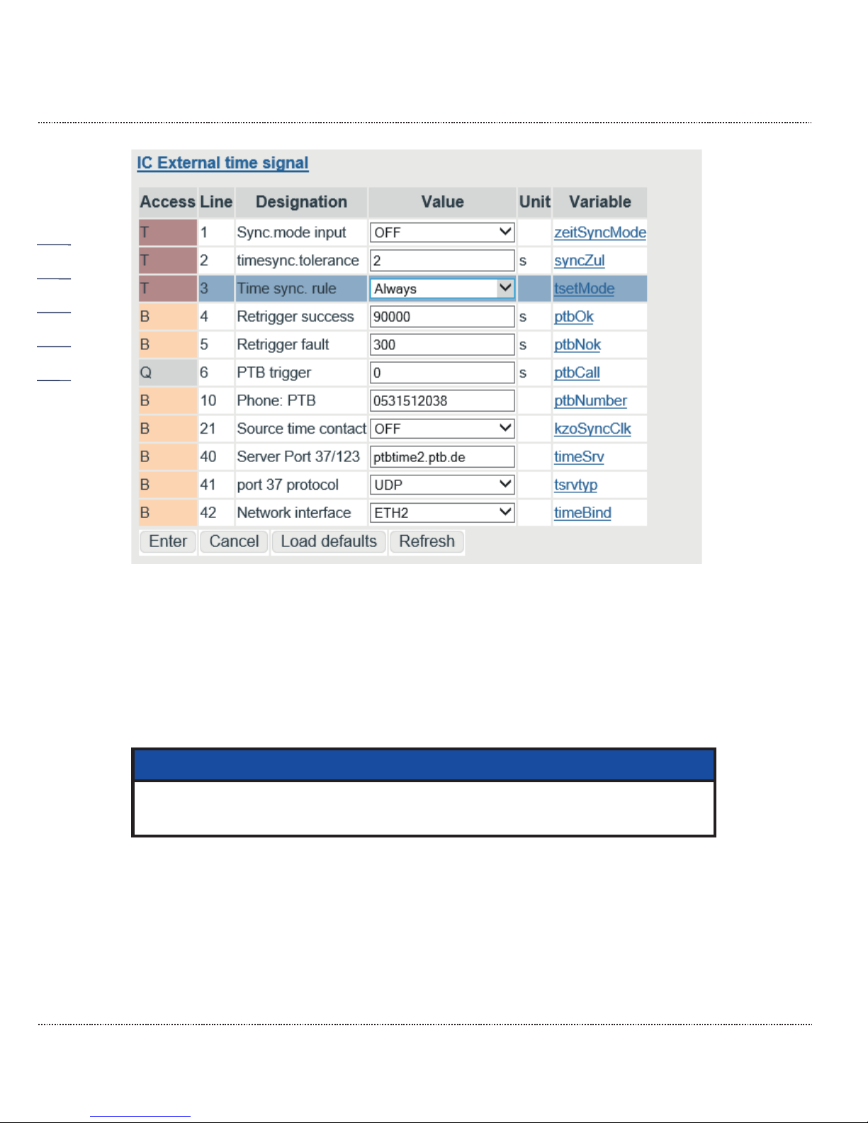
these changing values, e.g. an offset. Example: Remaining time / trigger (IC06) for
viewing the PTB telephone time service. IC06 contains the number of seconds until the next call of the telephone time service of the PTB. This call normally takes
place once per day. The time can be shortened for testing and the call-up can be
triggered prematurely.
Page 50
2 INTRODUCTION
Manual ERZ2000-DI · EN1.2 · 2017, December 21st
44
Figure 28: Automatically changing value "IC06 PTB trigger"
Trigger
These values basically have no function in the basic state. A task is assigned and
initiated with the editing. After completion of the task, the initiator returns to its
basic state.
Click on the white field to change the value and then write the desired value.
Note
Please observe the unit after these fields (e.g. IC06: unit = s [seconds])
and choose suitable entries.
Page 51
2 INTRODUCTION
Manual ERZ2000-DI · EN1.2 · 2017, December 21st
45
Parameter change:
There are different ways to change parameters:
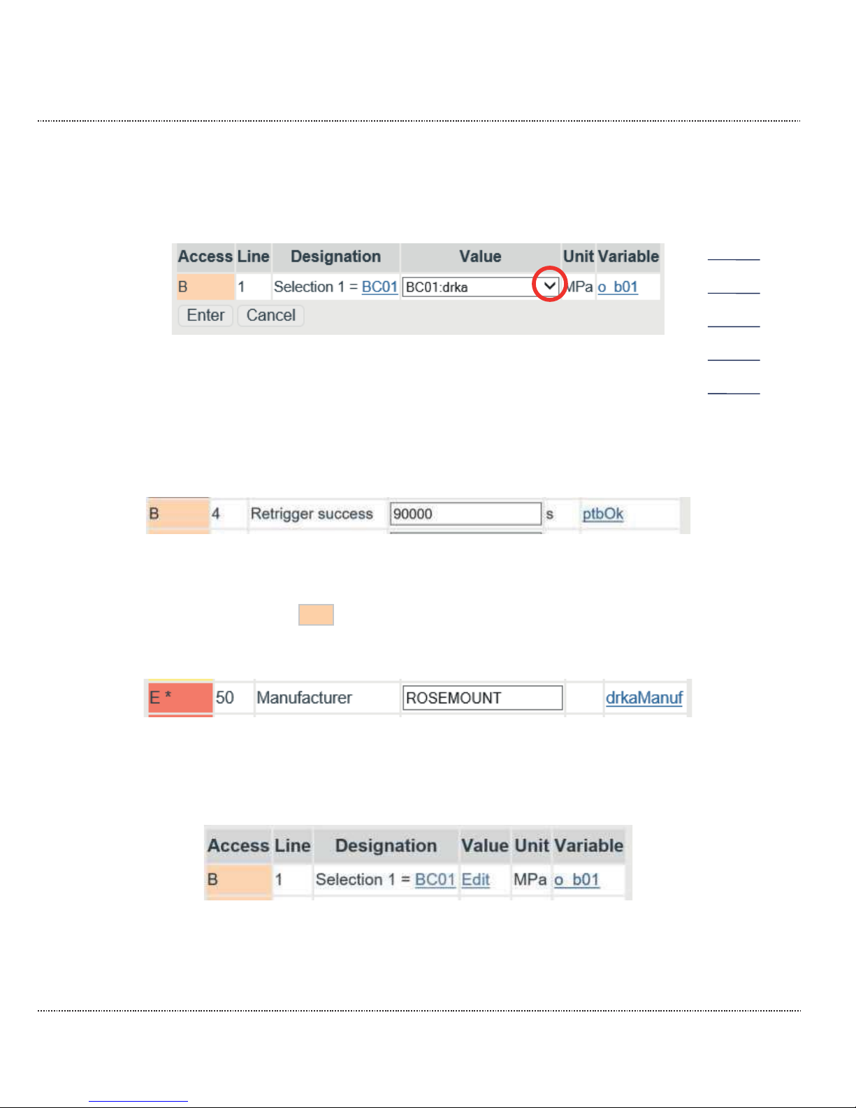
1. Fields with an arrow (e.g. specification of the parameter shown in "large")
Figure 29: "AB Large"
Clicking on the arrow (in the red circle) opens a selection menu (see above). The
desired value can be selected from these specification parameters.
Entries can be made directly in other fields, e.g. IC04 Retrigger success (see
Figure 28: Automatically changing value "IC06 PTB trigger"):
Figure 30: Entry in fields (numbers)
The desired time after which a re-login takes place is entered directly in the field
(with the example 90000 s ൎ 1 day), the assigned unit ( [s] ) was already assigned. Other fields contain additional information that can also be entered directly
(in Figure 31: Entry in fields (text) the manufacturer "Rosemount" is entered).
Figure 31: Entry in fields (text)
A final possibility is fields that can be activated (Figure 32: Activation of value
fields).
Figure 32: Activation of value fields
By clicking on the value: "edit", a sub-menu appears in which the variable BC01
Absolute pressure can be changed.
Page 52
2 INTRODUCTION
Manual ERZ2000-DI · EN1.2 · 2017, December 21st
46
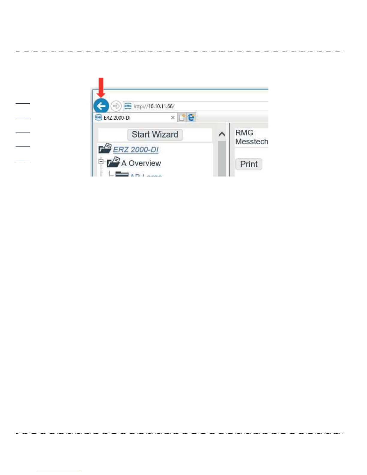
With the back arrow of Explorer
Figure 33: Back to the main menu
you return to the previous menu.
In order to familiarize yourself with the settings options and the type of setting, we
recommend testing the settings options in the various "menus" in this display with
the mouse. In order to avoid unnecessary "resetting", only save new settings if you
actually need them.
2.4 Access protection for data and settings
The ERZ2000-DI permits the entry and adjustment of all editable values. A de-
scription is provided in chapter 2.3.3 Display. All editable values are access-pro-
tected, which prevents arbitrary changes. This access protection has different hier-
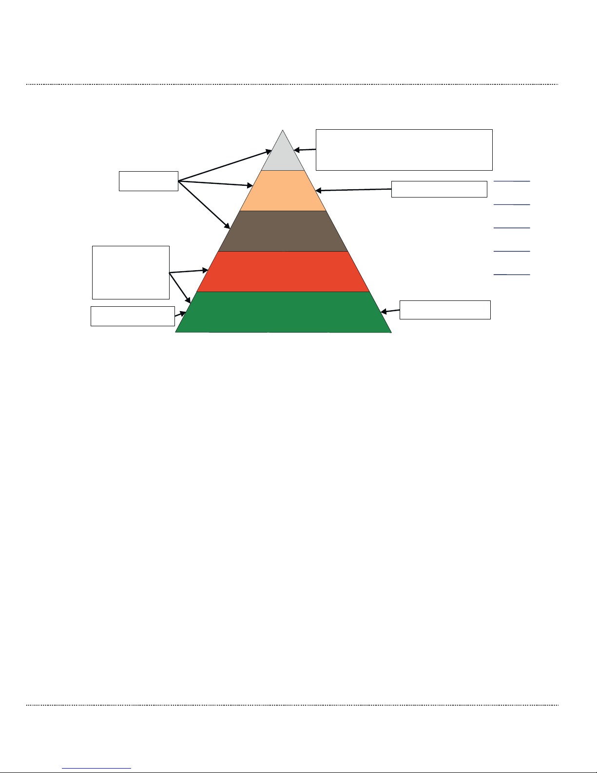
archies that are illustrated in the following figure:
Page 53
2 INTRODUCTION
Manual ERZ2000-DI · EN1.2 · 2017, December 21st
47
Figure 34: Hierarchy of access protection
The lowest protection level applies with a closed calibration switch and without entry of a protection code. With entry of the first protection code, you reach the next
protection level and entry of the second protection enables access to the third protection level.
These levels must be activated or deactivated by the user in order to make
changes.
The next protection level is subject to calibration protection and must only be
opened by authorized persons. The factory settings are also made in this level.
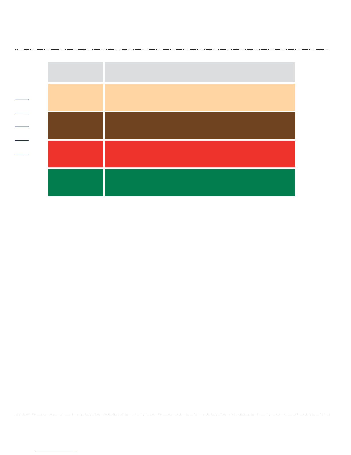
There is also a super user protection for the highest level. With higher protection
level, all lower protection levels are open. The following Table 2: Access rights ex-
plains the access rights for the different protection levels.
Super user
Calibration lock
Double code
Single code
closed
Operater
Access protection
User
Official
accepted
certifying body
certifyer
Without protection, can be used when
closed. Calibration switch and closed
code word must be activated.
Lowest protection
Highest protection
Factory setting
Page 54
2 INTRODUCTION
Manual ERZ2000-DI · EN1.2 · 2017, December 21st
48
Closed
Without influence on measurement and measurement accuracy,
e.g. operating point testing resolution
Single code
Without influence on measurement and measurement accuracy,
e.g. specification values, warning limits, plausibility, comparisons, user protocols
Double code
Adaptation of gas property tables, has influence on measurement, but is then permitted and desired. Permission takes place
with enabling of an operating mode protected by calibration lock.
Calibration
lock
With influence on measurement and measurement accuracy.
e.g. alarm limits, coefficients, operating modes (especially also
operating modes allowing permission),
Super user
With considerable influence on measurement and measurement
accuracy.
e.g. calibration values, equipment, enabling of functions, ..
Table 2: Access rights
Access rights can be changed in the menu "GA Access" (Figure 21: Access to the
device).
You can click on the fields after Codeword 1 and Codeword 2 and change the
value of the code words with keyboard entry. If the rotating calibration lock is already open, the currently set code word can be read under the code words. The
factory setting for both is "9999". This value must be entered (with calibration
turned back and closed) and activated with "enter". The field GA04 Current ac-
cess displays "single code". If Code word 2 is activated with the same code =
"9999" with the same procedure, then GA04 Current access displays "double
code". Separation between supplier and purchaser is possible with 2 different code
words.
The calibration lock on the front panel is opened by turning it clockwise and GA04
Current access displays "super user".
Without prior activation of Code words 1 and 2, GA04 Current access is "calibration lock".
Change of the code word
In "super user" access protection, the code word can also be changed. In the
menu "GA Access", the code words are read as encrypted numbers. If a new word
is entered for the code word (series of numbers), it is activated with "enter" (adopt)
for further activation of the access protection.
Page 55
2 INTRODUCTION
Manual ERZ2000-DI · EN1.2 · 2017, December 21st
49
Deactivation of the access protection
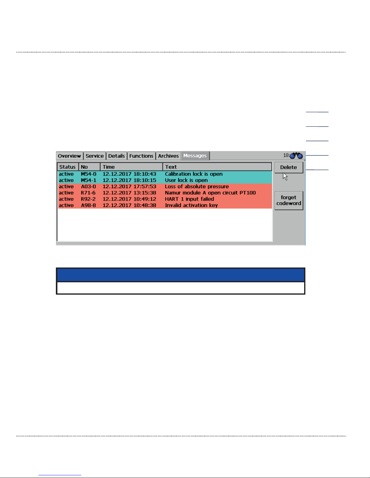
The access protection can be deactivated with the touchscreen of the ERZ2000-DI
(see Figure 35: Deactivation of the access protection) and with the browser (see
Figure 23: Error messages). The button "Forget code word" becomes visible in the
touchscreen display after clicking on the "Message" tab to the right (Figure 35: De-
activation of the access protection). By clicking on the button, "single code" and
"double code" are closed. The text on Figure 23: Error messages describes how to
activate the error message. The "single code" and "double code" access are also
closed here by clicking on the "Acknowledge faults" button. The calibration lock is
closed by turning it counterclockwise.
Figure 35: Deactivation of the access protection
Note
Normally, the calibration is now sealed by a calibration official.
In order to finish the adjustment of the access authorization and the user profile,
the user profile must be entered in the menu NA Wizard. This is carried out most
easily by opening the wizard (see above).
Page 56
2 INTRODUCTION
Manual ERZ2000-DI · EN1.2 · 2017, December 21st
50
2.5 Language setting
The ERZ2000-DI is normally pre-configured, and the ordered language is set. The
wizard also starts automatically in the pre-configured language.
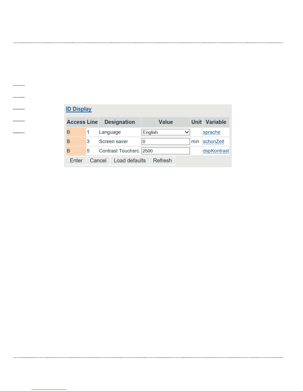
However, it may be necessary to change the language. This takes place in the
menu ID Display, see Figure 36: ID Display menu.
Figure 36: ID Display menu
First, select the language in the coordinate ID01 Language; "German" and "English" are available selections. After a change of the language and an update, all
texts and instructions of the ERZ2000-DI and the wizard language are changed.
2.6 Screen saver
The time after which the screen switches off following a period of inactivity is entered in the coordinate ID03 Screen saver. The coordinate ID05 EE05 Contrast
Touchscr. control the resolution of the display; the brightness of the screen can
be adjusted from 1000 to 4000 with a presetting of 2500.
2.7 Display screen
Representations of the touch screen of the ERZ2000-DI are shown below. For this
purpose, supplementary explanations of the figures on the browser are provided, if
applicable. After the power is connected to the ERZ2000-DI, it displays the home
screen, which is visible in Figure 37: Start screen.
Page 57
2 INTRODUCTION
Manual ERZ2000-DI · EN1.2 · 2017, December 21st
51
Figure 37: Start screen
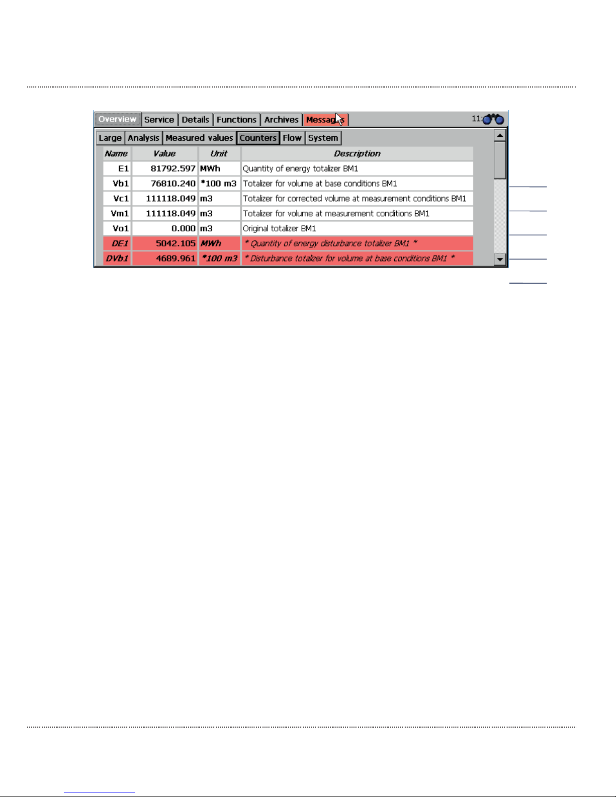
The home screen appears after each restart of the device or after pressing the
"HOME" key. This home screen shows the active meters, which are framed in italics with " * " according to calibration authority specifications. The other meters become visible with vertical scrolling (right).
Pressing the right tab in the upper area of the screen takes you to further display
screens. The display screens are arranged like tabs. They represent the top level
of the operating menu and are accessible via the buttons on the upper bar. The
following display pages, "menus" are available, where the following sections are
displayed.
Overview Home screen with the meters
(and important measurements)
Service Service functions
Details List of all measurements and parameters of the
ERZ2000-DI
Functions Displays and functions for test and calibration
Archives Archive entries
Messages Color event and error messages
(alarms, warnings and notices)
Changes/settings can be made in some of the display screens. To change this parameter, go to the appropriate field or the appropriate line and the input fields ap-
pear, as shown in the example in Figure 38: Input field:
Page 58
2 INTRODUCTION
Manual ERZ2000-DI · EN1.2 · 2017, December 21st
52
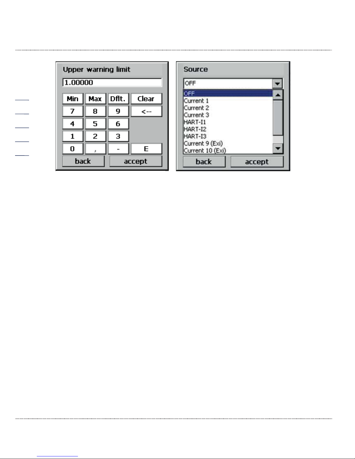
Figure 38: Input field
The left field is provided for entry of the numerical values; the right field is provided
to select a mode. The new numerical value and/or the new mode is adopted with
"accept".
2.7.1 Overview
Scroll to the top in the overview or tap on the "Overview" menu item again; six selection fields which can be used to switch to other tables, e.g. display screens, appear in the upper line.
2.7.1.1 Large
The "Large" display was already described above. This can be used to display 4
specific parameters in an extra-large font in order to enable a reading from a
greater distance.
Page 59

2 INTRODUCTION
Manual ERZ2000-DI · EN1.2 · 2017, December 21st
53
2.7.1.2 Analysis
Figure 39: Overview -> Analysis sub-menu
The calculation process and corresponding input and result values are displayed
in this menu. The calculation process of the compressibility number is specified in
the first line – GERG 88S in this case.
In addition to further gas-specific parameters, the data for the gas composition that
varies depending on the selected calculation process is provided here.
The calculation process can be changed on the BH Calculation of K coefficient
wizard screen. This is equally possible in the corresponding menu.
2.7.1.3 Measurements
Figure 40: Overview -> Measurements sub-menu
The pressure and temperature measurements are shown in this display.
Page 60
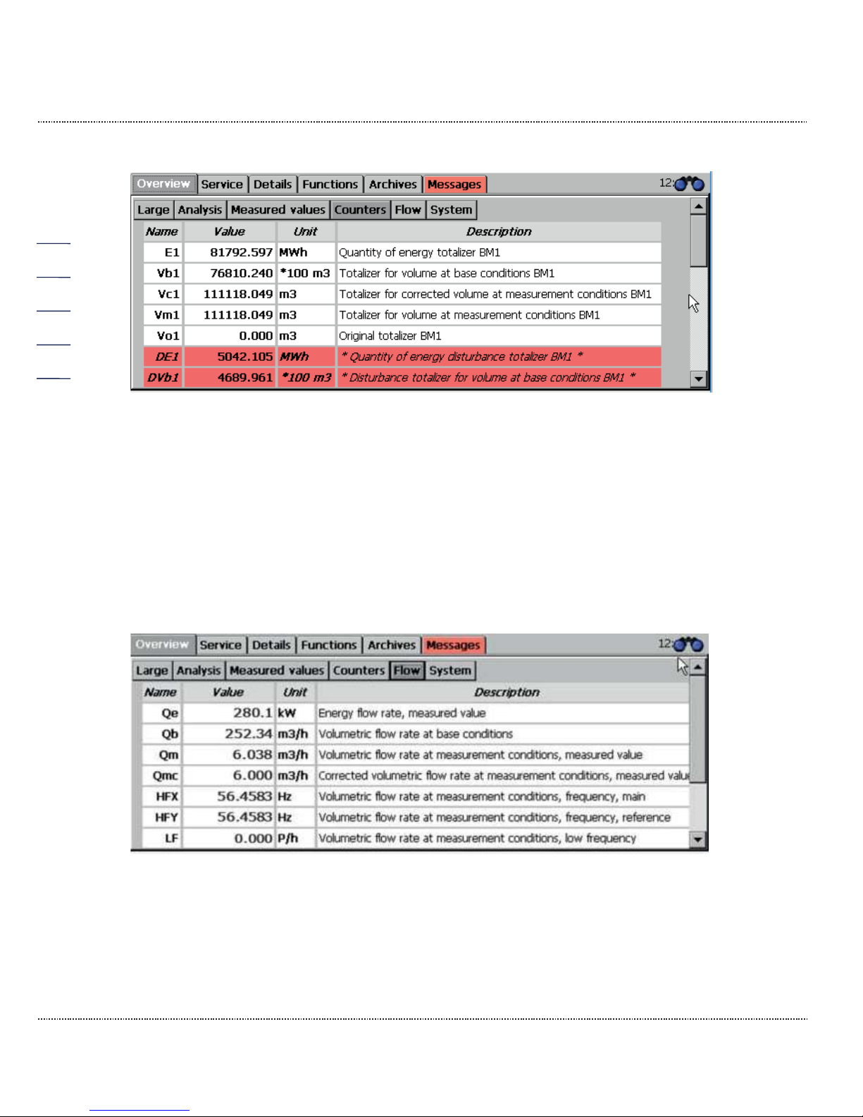
2 INTRODUCTION
Manual ERZ2000-DI · EN1.2 · 2017, December 21st
54
2.7.1.4 Counters
Figure 41: Overview -> Meters sub-menu
This menu shows the various meters for the two calculation modes, a color underline assigns different times or other classifications to the meters.
The appendix B) Totalizer in the browser view shows how the meters are handled
in the browser display.
2.7.1.5 Flow rate
Figure 42: Overview -> Flow rate sub-menu
This menu shows different flow rates, such as energy flow, nominal volume flow
and operating volume flow or the measurement current.
Page 61
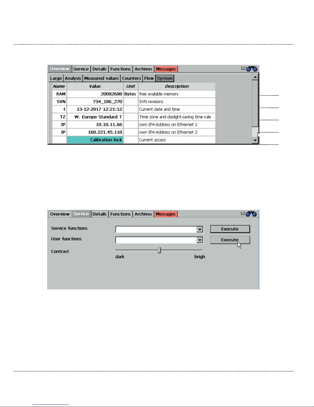
2 INTRODUCTION
Manual ERZ2000-DI · EN1.2 · 2017, December 21st
55
2.7.1.6 System
Figure 43: Overview -> System sub-menu
Various general values are displayed here, including the IP addresses with which
you can actuate the device if it is connected to the PC, a PLC, etc. via Ethernet.
2.7.2 Service
Figure 44: Service menu
The available settings in "Service functions" are reserved for the service department and a calibration official and/or an officially recognized inspection authority.
These functions are described in the appendix E) Service functions.
If a blur occurs on contact of the stylus with the touchscreen, calibration can take
place in the "Calibrate stylus" menu item under "User functions". Then this is initiated after selection of "Execute".
Page 62
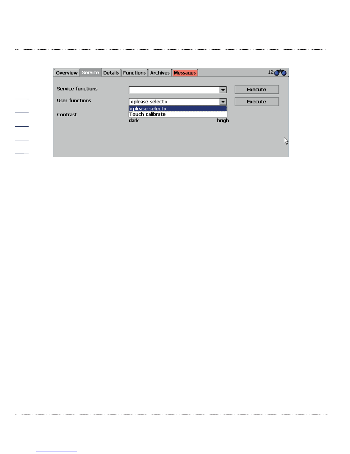
2 INTRODUCTION
Manual ERZ2000-DI · EN1.2 · 2017, December 21st
56
Figure 45: "Calibrate stylus" service menu / sub-program
After the function starts a series of crosses that must be touched in the center is
displayed. After this takes place touching the touchscreen again returns to the previous screen.
This calibration can take place at any time. The contrast can also be changed in
the service menu at any time. The stylus calibration can also be activated by
pressing the home button on the overview page and drawing a line covering about
1/3 of the screen width. Then the stylus calibration opens automatically.
2.7.3 Details
A list of all measurements, computed values, calculated variables, parameters,
functions and operating modes is provided here. The data is shown in a structure
like in the display with an internet browser; as viewed from the left, you see the superordinate menu tree, which can be opened by "clicking" with the stylus on the
touchscreen or by clicking with the right mouse pointer in the PC display for the
sub-menus. Figure 46: Details menu shows the screen.
Page 63
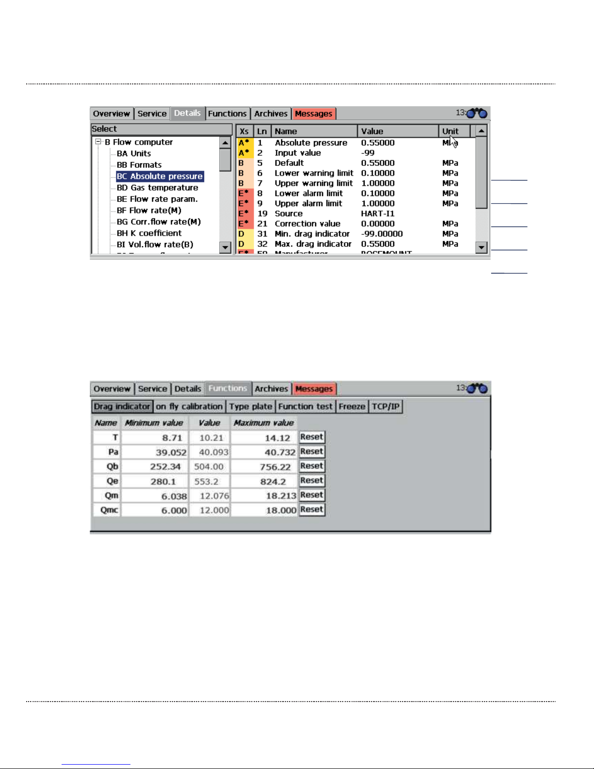
2 INTRODUCTION
Manual ERZ2000-DI · EN1.2 · 2017, December 21st
57
Figure 46: Details menu
Chapter 2.1.3 Remote control / parameterization explains how parameters can be
changed.
2.7.4 Functions
Figure 47: "Drag pointer" sub-menu under "Functions"
The "Functions" menu opens 6 additional display views, which are presented below. The drag pointer function is displayed first.
Page 64
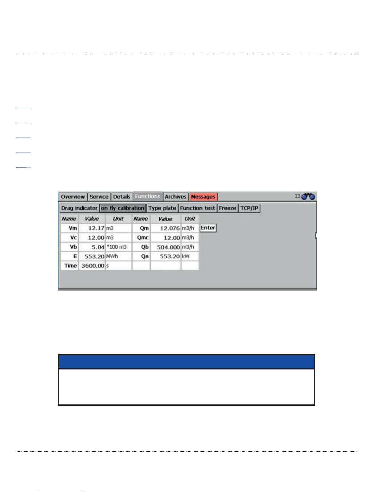
2 INTRODUCTION
Manual ERZ2000-DI · EN1.2 · 2017, December 21st
58
2.7.4.1 Drag pointer
The absolute minimum and maximum values for the measurements since the last
restart or since the last resetting of the drag pointer are shown here. The function
can be used for different measurement variables and is specified, for example,
with the BC Absolute pressure in the coordinates BC31 Min. drag pointer. and
BC32 Max. drag pointer. With other measurement variables, where this function
can also be used, the settings are also in lines 31 and 32. These values specified
for the "drag pointer" are deleted with "Reset" and then the set to the current
measurement. The display is shown in Figure 47: "Drag pointer" sub-menu under
"Functions". The drag pointers can also be reset globally in the LE Erasing proce-
dure menu.
2.7.4.2 On-the-fly calibration
Figure 48: "On-the-fly calibration" sub-menu under "Functions"
Meters that can be started like a stopwatch at 0 are shown in this screen. It is
started with "Enter" – to the right of the values. The meters then run until "En-
ter" is pressed again. Pressing "Enter" again resets the meters to 0 and initiates a
restart.
Note
Tip:
When the time marks: 36 s, 360 s and 3600 s are reached, the meter values
of meter and flow can be compares most easily *
1
.
2.7.4.3 Type plate
*1 Frequency conversion (unit Hz = 1/s) to volume flow (unit V = m³/h) the factor is set to 3600;
rounding, which occurs with other time marks is omitted here.
Page 65
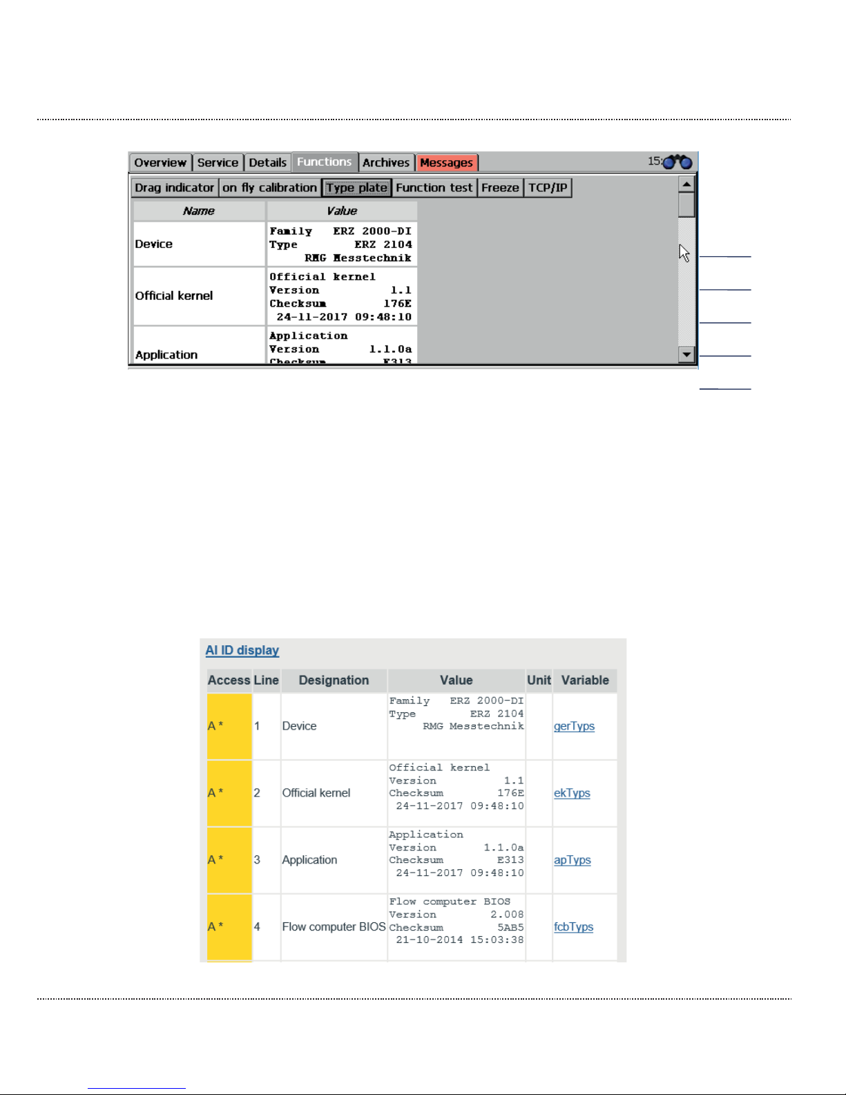
2 INTRODUCTION
Manual ERZ2000-DI · EN1.2 · 2017, December 21st
59
Figure 49: "Type plate" sub-menu under "Functions"
The type plate of the device is displayed in the "Type plate" submenu. This included further data, e.g. about the electronics (calibration kernel, Bios, WinCE kernel), about the meters and their settings (dimensions, pulse value), about the type
of gas (composition, velocity of sound) and the environmental and standard conditions (pressure, temperature).
Only the type plate data is displayed here; there is no input possibility in the type
plate display. Entry of the values takes place by entering the parameters of the rel-
evant transmitter devices (chapter "4 Transmitters")
The type plate can also be viewed in the browser under the menu AI ID display.
…
Page 66
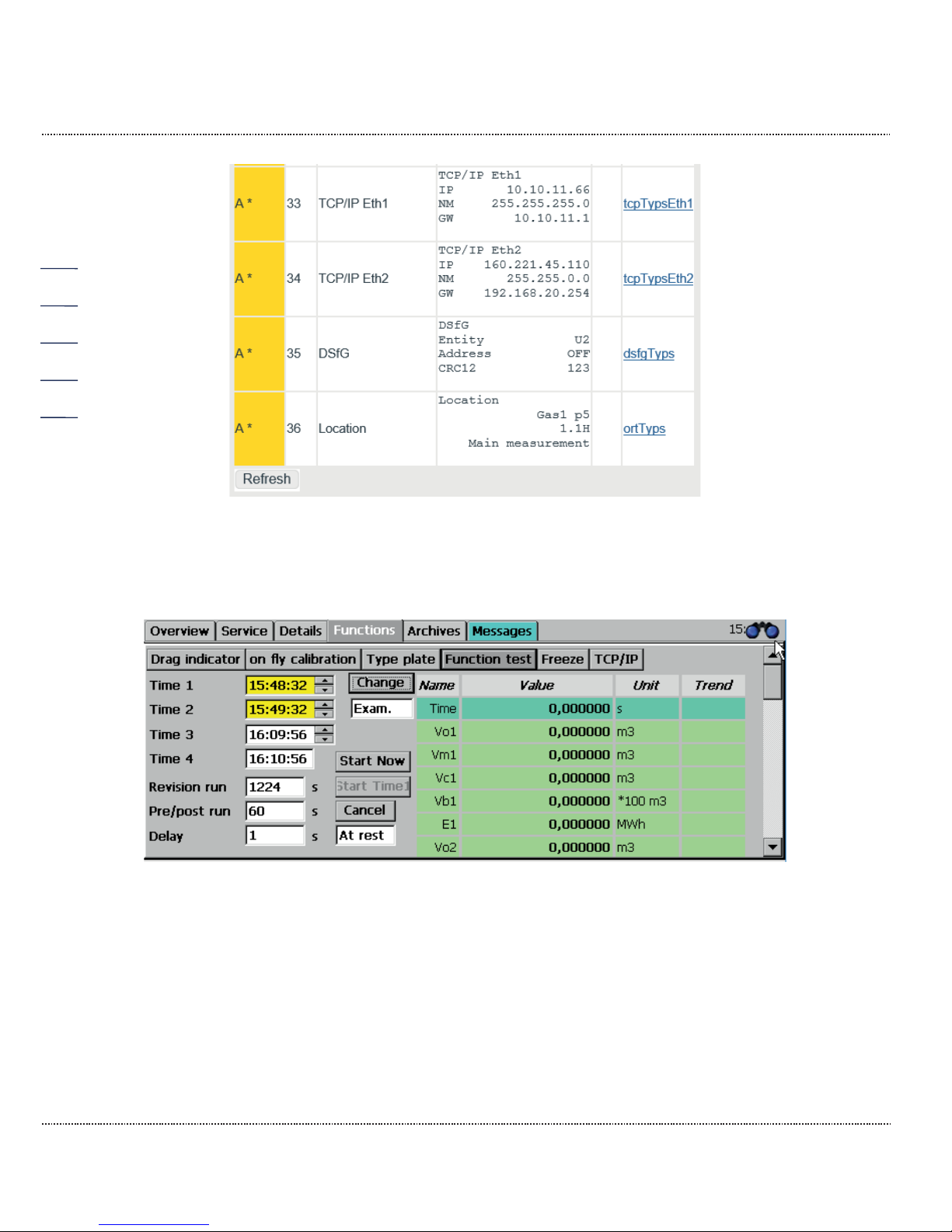
2 INTRODUCTION
Manual ERZ2000-DI · EN1.2 · 2017, December 21st
60
Figure 50: AI Type plate menu
2.7.4.4 Functional test
Figure 51: "Functional test" sub-menu under "Functions"
The quantities and measurements are recorded and displayed for a defined length
of time in the functional test. The functional test is divided into a run-up, the actual
test and an after-run.
Page 67
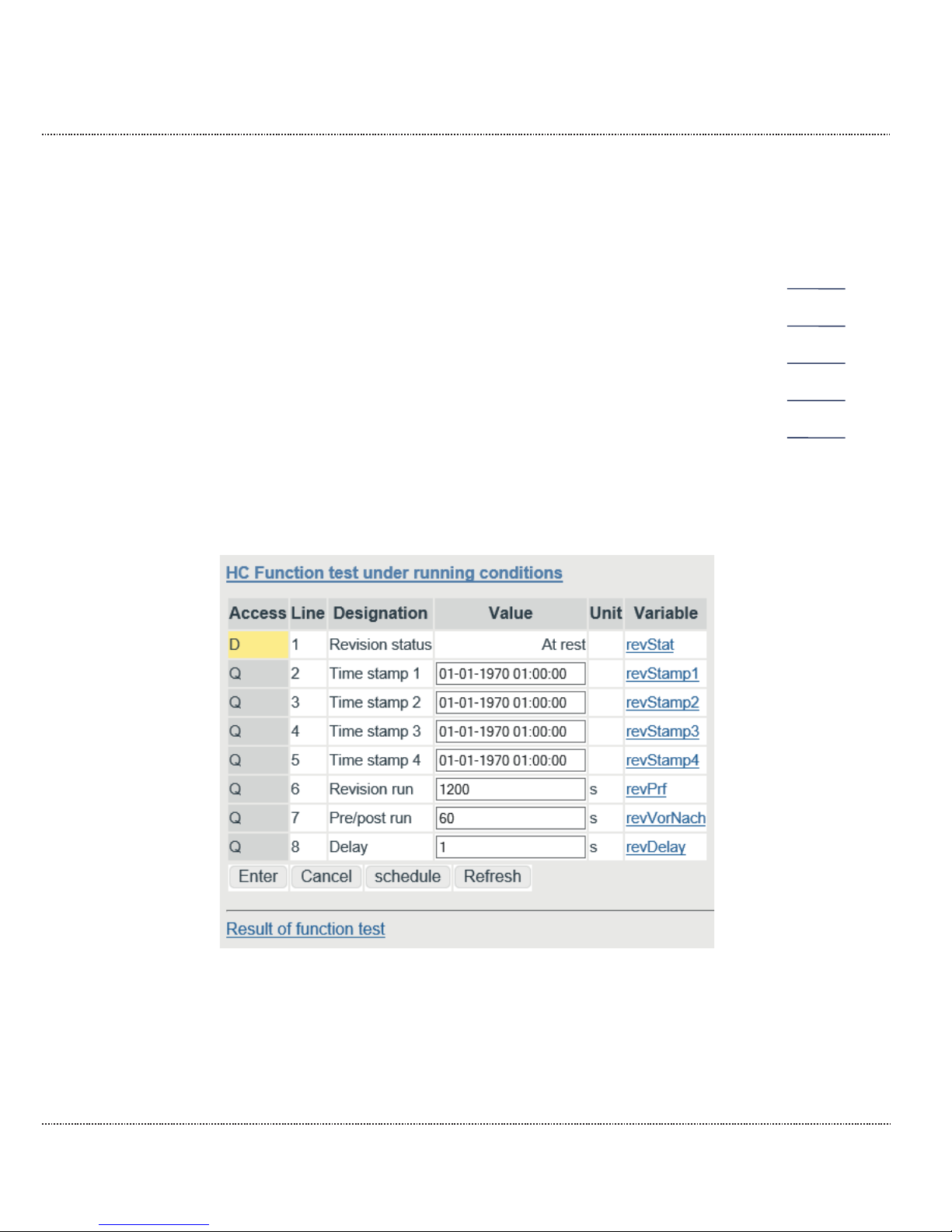
2 INTRODUCTION
Manual ERZ2000-DI · EN1.2 · 2017, December 21st
61
Functional test process:
1. Enter four times for the three sections of the functional test.
2. Click on the "Start Time1" button. Then the functional test is run according to
the four times. Times that have already elapsed are highlighted green. Blinking
green times indicate the functional test progress.
3. Alternatively, you can press the "Start now" button. Time 1 is set to the current
time and the test starts immediately with the run-up time. Run-up, after-run and
test times proceed according to the specifications. The time progress is also
displayed here in green and blinking green.
4. If the testing is finished, the 4 time fields are highlighted yellow.
5. The result can be read in the green highlighted table to the right. You can
switch back and forth between the tables for run-up, test and after-run with
"Change".
Alternatively, the times for test time, run-up and after-run, as well as a delay time
can be entered. The results of the functional test are also saved in archive groups
17 to 20.
Figure 52: HC Function test menu
In order to receive logical values with appropriate resolution, an adequate test time
must be provided. A few minutes are sufficient for the volume detection via the HF
inputs, because synchronization of the test function with the recording of the volume frequency takes place. For "slow" inputs, such as interfaces with ENCO or ultrasonic gas meters, the test time must be sufficiently long to minimize resolution
Page 68

2 INTRODUCTION
Manual ERZ2000-DI · EN1.2 · 2017, December 21st
62
error (e.g. 1200 seconds = 20 minutes). This also applies for the "On-the-fly calibration" function.
The coordinates of the menu in detail:
HC01 Revision Status Shows the current status of the function
(stationary / running)
HC02 Time stamp 1 Parameter for starting the test process (run-up start)
HC03 Time stamp 2 Parameter for stopping the run-up and starting the ac-
tual test
HC04 Time stamp 3 Parameter for stopping the test and starting the after-
run
HC05 Time stamp 4 Parameter for stopping the after-run and the function
HC06 Revision run Parameter for a relative specification of the test time,
corresponding to the time between Time stamp 3 and 4
HC07 Pre/post run Parameter for a relative specification of the run-up and
after-run time, corresponding to the time between Time
stamp 1 and 2 or 3 and 4
HC08 Delay Parameter for a wait time before the start with Time
stamp 1
There are multiple processes for using the Functional testing function.
Use of the time stamp with manual entry.
If the 4 time stamps are entered, activate the "Start Time1" button. Then the function starts automatically when the times are reached and stops after the 4th time
stamp has elapsed. The test time, the time for run-up/after-run and the delay are
calculated and adopted from these times.
There is also a very simple option for activating a functional test directly by clicking
on the "Start now" button. For this purpose, the test time and run-up/after-run must
be specified beforehand.
Parameterization of the time stamp with entry by means of remote operation
via the browser.
For this purpose, click on the "schedule" button under the table. The 4 time
stamps are calculated from the PC time (not the flow computer time!) and the values for test time, run-up/after-run and delay. The function starts automatically
when the times are reached and stops after the 4th time stamp has elapsed.
The result of an elapsed function test can be viewed in the browser. For this purpose, click on the "Result of function test" button under the table in the menu HC
Functional test under running conditions (Figure 52: HC Function test menu)
Page 69
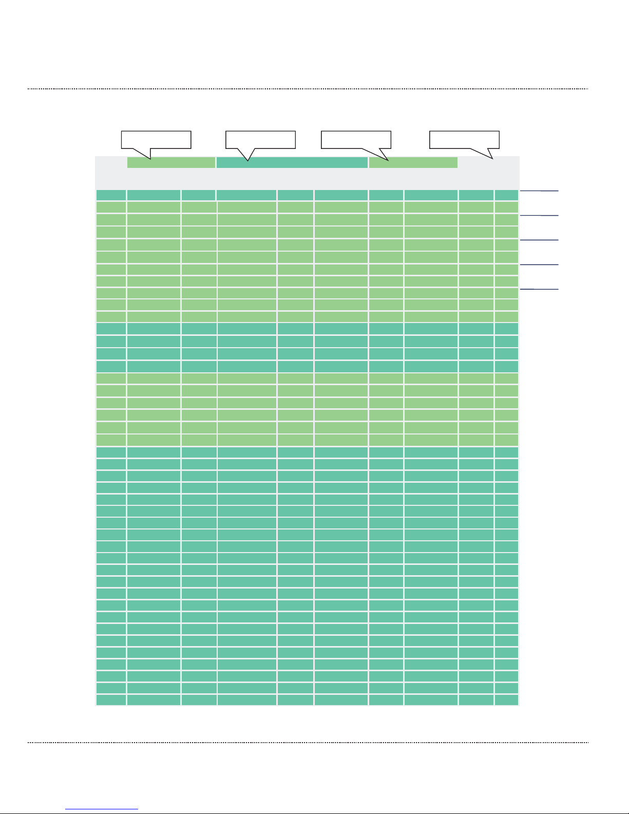
2 INTRODUCTION
Manual ERZ2000-DI · EN1.2 · 2017, December 21st
63
Functional test under running conditions
Pre run
Examination
Post run
Designation
13-12-2017
15:57:41
-
13-12-2017
15:58:41
-
13-12-2017
15:59:57
-
13-12-2017
16:00:57
Unit
Trend
Time
22459.647093
59.996115
22519.643209
75.995960
22595.639168
59.996881
22655.636049
s
Vo1
0.000000
0.000000
0.000000
0.000000
0.000000
0.000000
0.000000
m3
Vm1
111118.048975
0.326637
43045.224940
1.959824
111118.048975
0.326637
111118.048975
m3
Vc1
111118.048975
0.326637
43045.224940
1.959824
111118.048975
0.326637
111118.048975
m3
Vb1
76810.239998
12.228196
1354422.625786
73.369174
76810.239998
12.228196
76810.239998
*100 m3 E1
81792.596735
0.122184
24540.661667
0.733105
81792.596735
0.122184
81792.596735
MWh
Vo2
0.000000
0.000000
0.000000
0.000000
0.000000
0.000000
0.000000
m3
Vm2
1157.746350
0.000000
1157.746350
0.000000
1157.746350
0.000000
1157.746350
m3
Vc2
1157.746350
0.000000
1157.746350
0.000000
1157.746350
0.000000
1157.746350
m3
Vb2
1435.567757
0.000000
1435.567757
0.000000
1435.567757
0.000000
1435.567757
*100 m3
E2
1658.080787
0.000000
1658.080787
0.000000
1658.080787
0.000000
1658.080787
MWh
Qm
117.589
117.589
117.589
m3/h
↑
Qmc
117.589
117.589
117.589
m3/h ↑ Qb
4402.15
4402.15
4402.15
m3/h ↑ Qe
43986.2
43986.3
43986.3
kW
↑
Pa
0.55000
0.55000
0.55000 MPa
T 293.15
293.15
293.15 K
↓
Hs 11.250
11.250
11.250
kWh/m3
sd
0.75651
0.75651
0.75651
kg/m3 ↑ C 5.0577
5.0577
5.0577
↑
K
1.00000
1.00000
1.00000
↓
CO2 0.0000
0.0000
0.0000
mole% H2 0.0000
0.0000
0.0000
mole%
N2 0.0000
0.0000
0.0000
mole%
CH4
100.0000
100.0000
100.0000
mole%
C2H6 0.0000
0.0000
0.0000
mole%
C3H8 0.0000
0.0000
0.0000
mole%
N-C4 0.0000
0.0000
0.0000
mole%
I-C4 0.0000
0.0000
0.0000
mole%
N-C5 0.0000
0.0000
0.0000
mole%
I-C5 0.0000
0.0000
0.0000
mole%
NeoC5 0.0000
0.0000
0.0000
mole%
C6 0.0000
0.0000
0.0000
mole%
C7 0.0000
0.0000
0.0000
mole%
C8 0.0000
0.0000
0.0000
mole%
C9 0.0000
0.0000
0.0000
mole%
C10 0.0000
0.0000
0.0000
mole%
H2S
0.0000
0.0000
0.0000
mole%
H2O 0.0000
0.0000
0.0000
mole%
He 0.0000
0.0000
0.0000
mole%
O2 0.0000
0.0000
0.0000
mole%
CO 0.0000
0.0000
0.0000
mole%
Ar 0.0000
0.0000
0.0000
mole%
Table 3: Explanation of terms Transfer of the volume transmitter
Time stamp 1
Time stamp 2
Time stamp 3
Time stamp 4
Page 70
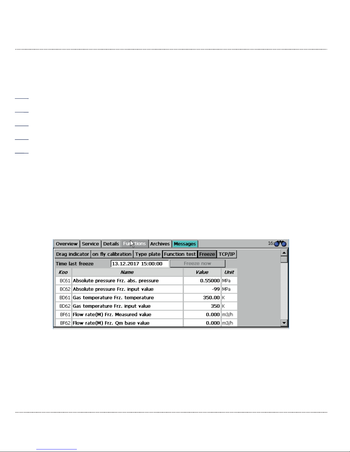
2 INTRODUCTION
Manual ERZ2000-DI · EN1.2 · 2017, December 21st
64
The center row with 3 columns and the test heading (bold) is the result of the function test. The first column displays the initial values, the center column the differences and averages and the third column the stop values. Run-up and after-run
are relevant data depending on the logical test times.
The function test then delivers usable data if the flow computer runs error-free and
does not change during the test of the totalizer status (running / stopped). If this is
not the case, the starting and stopping values are not displayed and the lines with
the totalizer statuses are hidden. If, for instance, only the disturbance totalizer are
running, the stationary main totalizer are stored with the difference = 0. For interface protocols that only send the data in second-long intervals, the test time must
be given more attention (ENCO, DZU). The same also applies for LF inputs.
2.7.4.5 Freeze
The ERZ2000-DI offers the option of temporarily storing current data for later use.
This is referred to as a freeze. The last quantities and measurements are "frozen"
with the freeze function. First, the ERZ2000-DI reports the recording of all data
and the configuration of the table. This can take several seconds, then the data
that was recorded on the specified date and time.
A freeze is most easily activated by pressing the "Freeze now" button.
Figure 53: "Freeze" sub-menu under "Functions"
Figure 54: HA Freeze menu shows the menu HA Freeze under "H Revision".
HA01 shows the time of the last archiving, coordinates HA03 to HA05 can be
used to adjust when and how the freeze function is activated. HA04 defines the
time interval over which the data is recorded and archived. In coordinate HA05
Source freeze cont. the corresponding contact input 1 to 8 must be set if a
"Freeze" should be initiated by a contact pulse.
Page 71
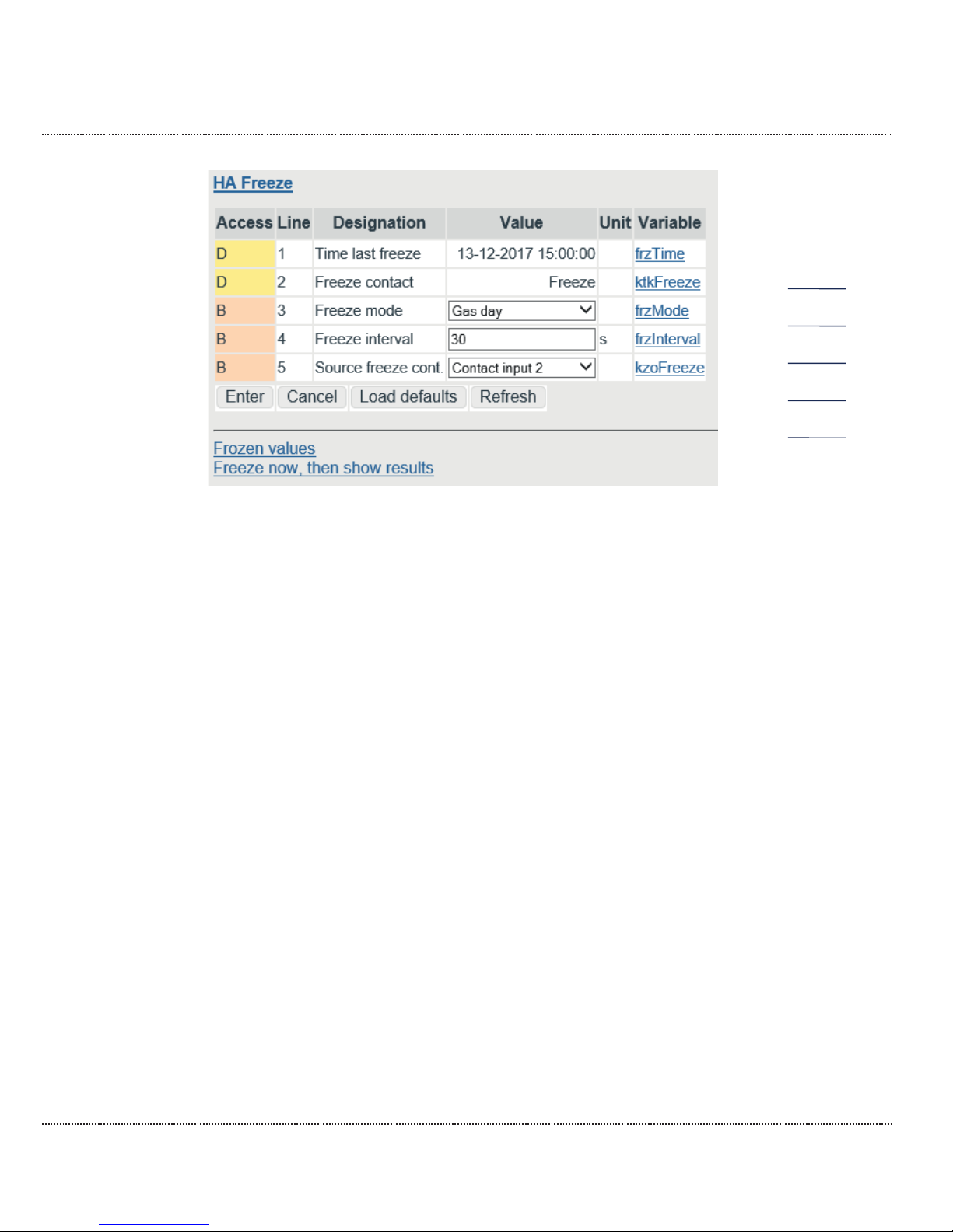
2 INTRODUCTION
Manual ERZ2000-DI · EN1.2 · 2017, December 21st
65
Figure 54: HA Freeze menu
The selection of how frequently the freeze process is initiated (HA03 Freeze
mode) is:
Off No freeze processes are initiated and the freeze dialog is deactivated.
Every second
Freeze in second intervals
Every minute
Freeze in minute intervals at the start of a minute
Every hour
Hourly freezing at the start of an hour
Every day
Daily freeze at the start of the day
Gas day
Freeze is initiated on the specified gas day ("YA27 Gas day")
at the beginning of the specified billing hour. The billing hour
must be specified; day, month and year are specified automatically.
Cyclical
Cyclical freeze in the
specified interval (coordinate "HA04
Freeze interval")
Contact
Initiate freeze via a selectable contact input; e.g. if freeze is initiated with buttons via Contact input 2
Manual
The "Freeze now" button is activated in the freeze dialog.
Every month
Monthly freeze on the 1st day of every month
Page 72
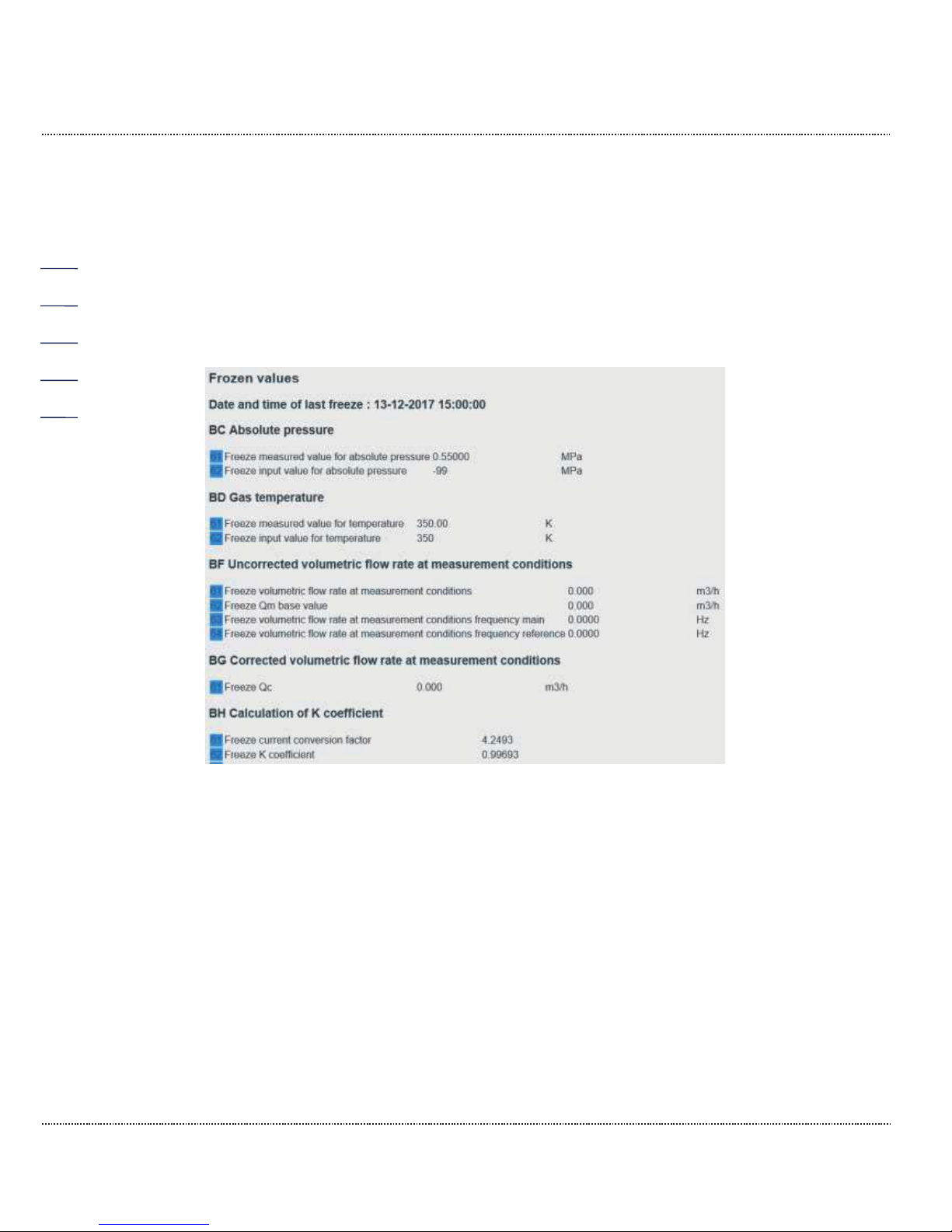
2 INTRODUCTION
Manual ERZ2000-DI · EN1.2 · 2017, December 21st
66
Gas month
The freeze is initiated in the specified month (coordinate "YA28
Gas month") at the beginning of the specified billing hour and
specified day (coordinate "YA27 Gas day").
The billing hour and day must be specified; month and year
are specified automatically.
The freeze results can be displayed in the browser (function under the menu
HZ Freeze). They are stored in the blue fields.
Figure 55: Display of the last freeze values
2.7.5 Archive
The archive entries of all archive groups can be viewed in this screen. The entries
are numbered from "Start" to "End", where the initial value is set to 1. If the index
has reached the maximum buffer depth, the oldest entry is overwritten when a new
data record is generated starting at this point. Then the start index increases by 1
each time.
Page 73
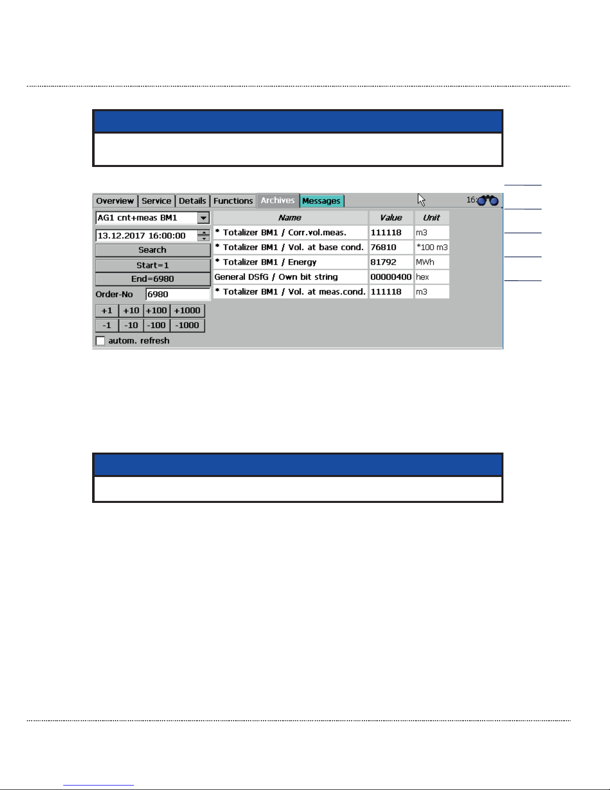
2 INTRODUCTION
Manual ERZ2000-DI · EN1.2 · 2017, December 21st
67
Note
Only display is possible on the device; the archive content can also be exported in the Excel-compatible tsv format with the internet browser.
Figure 56: "Archive"
Call-up of archive data
The desired archive group (AG) is selected at the top left. A search time can be
entered in the field below it. After pressing "Search", the entry is displayed to the
right with this date and time.
Note
If no entry exists with this time, the next newest data record is displayed.
Two fields for jumping to the oldest or newest entry are included. The indenture
number indicates the current position, i.e. the index of the displayed entry. Jumps
of ±1, ±10, ±100 and ±1000 positions can be made with the fields below.
The display can be automated so that the last stored value is always displayed.
For this purpose, the last data record (end) must be selected first, then the function "Autom. refresh" must be activated. If the newest data record is not displayed,
the check box is deactivated and meaningless. "End" must be actuated before the
automation is reactivated. The actualization process is displayed with a blinking of
the background color of the check box. In the process, color-coding differentiates
between updating and updating and display of a new data record.
The values in the table can have different background colors:
Page 74

2 INTRODUCTION
Manual ERZ2000-DI · EN1.2 · 2017, December 21st
68
White
Error-free measurement
Gray
Meter/measurement has stopped
Blue
Substitute value
Green
Fixed value
It is possible to freely define a special archive. The content and recording
cycle can be selected arbitrarily by the user. The complete scope of all
measurements and values are available via a selection menu for the storage
of data, comparable to the selection for the current outputs (Figure 57: Free
programmable archive menu).
Parameterization of the archive content takes place under JN Free programmable archive. For selection of content, the appropriate coordinate to be archived
must be selected under "Name" under JN10 Assign. Channel 1. Any other arbitrary value can be assigned via a selection menu. Up to 20 coordinates can be assigned in this manner. Entry for the user code is suitable for access.
The ERZ2000-DI writes the result-controlled (e.g. with incoming and outgoing errors or with full hours or .. ) meter statuses, measurements and messages in its archive. For this purpose, there are different archives, e.g. for main meters, disturbance meters or special measurements. It also determines the highest values from
the measurements, which are displayed and written to the appropriate archive
groups.
The time grids are adjustable with the coordinate "JN01 Record cycle":
Off, every minute, every 2nd minute, every 3rd minute, every 4th minute, every 5th
minute, every 6th minute, every 10th minute, every 12th minute, every 15th minute, every 20th minute, on minute 30, every hour, every day, gas day, every
month, gas month, on ever freeze cycle and on every change of the gas composition.
The archive depth is 8192 entries.
Page 75
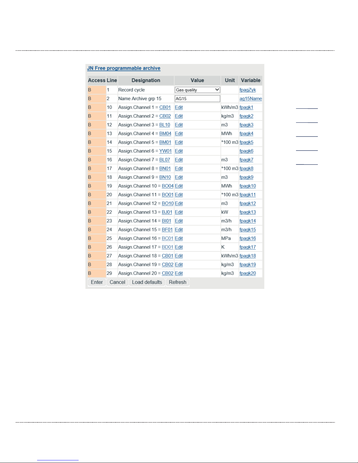
2 INTRODUCTION
Manual ERZ2000-DI · EN1.2 · 2017, December 21st
69
Figure 57: Free programmable archive menu
Deletion of archives, log books, change buffer, etc.
In the menu L Factory setting, sub-menu LE Erasing procedures (Figure 58:
Menu LE Erasing procedures), archives, log books, etc. can be deleted. As a Su-
per user (see chapter 2.4 Access protection for data and settings) the coordinates
LE10 Clear log, LE11 Clear changes, LE12 Clear archive (DSfG archive of the
flow computer and registry entry, as well as the DSfG log book), LE13 Hour/day
reset (DSfG Archive for the highest load), LE14 Drag indic. reset (max and min
values of all drag pointers, values are set to the current values) and LE16 Clear
exceptions are activated.
Page 76
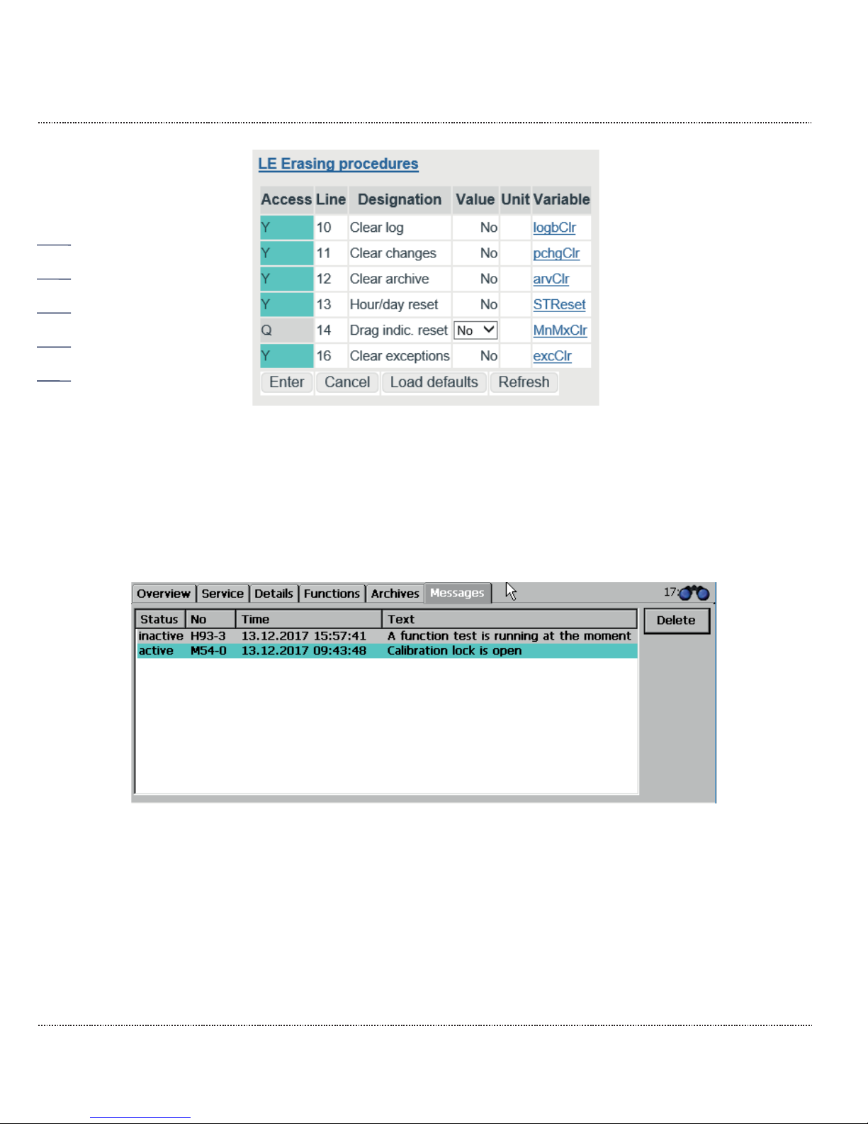
2 INTRODUCTION
Manual ERZ2000-DI · EN1.2 · 2017, December 21st
70
Figure 58: Menu LE Erasing procedures
Further details about the archive are provided in the appendix C) Archive assignment, depth and identification.
2.7.6 Alarm, warning message
Figure 59: "Messages"
All messages that have taken place since the last deletion are displayed in different colors in this field:
Page 77

2 INTRODUCTION
Manual ERZ2000-DI · EN1.2 · 2017, December 21st
71
Red
Pending alarms, i.e. faults of the custody transfer functions that result in counting in the disturbance meters. General alarms are identified with "A"; internal computer errors are identified with "R".
Yellow
Current warnings, identified with "W", that refer to an error of a
non-custody-transfer function. The main meters continue to run.
Light
blue
Notices ("H") of implausible parameterization or potentially faulty
operating statuses.
Turquoise
Messages ("M") normal operating statuses, e.g. "User lock is
open".
Gray
Alarms or warnings that are temporary, have not been acknowledged, but are no longer present.
LED status:
blinking /
continuously
illuminated
Warning and alarm messages are displayed by a yellow
(warning) and a red (alarm) LED on the front side of the device. The blinking LED indicates an active message. If a
continuous light is present, the warning (alarm) is no longer
present, but the message
has not been deleted yet.
If multiple messages are pending simultaneously, the
blinking status has priority.
Relay closes
The warning relay and/or alarm relay closes in parallel.
If single-value and double-value messages are differentiated between; a singlevalue message appears and then is pending permanently, the two-value message
is always present, but with interruptions. There is only one status for single-value
messages: "Message is active"; the active status for these messages remains in
effect until acknowledgment. The warning or alarm relay is energized if a (or multiple) message(s) occurs (occur) and reset if no messages are present. The relays
remain active for single-value messages until acknowledgment.
All messages that have not been acknowledged are shown in the display. With
"Delete", the no longer pending alarms and warnings and all other messages are
deleted from this display. With "Delete", the relevant LEDs are also deactivated, if
no alarm or warning is pending. However, the deleted messages are stored in the
log book (archive group 21). If no events are pending, the following text appears:
"no errors".
The "Message" tab is displayed in the color of the message having the highest
value if you are in other menus / screens.
Warning and alarm messages can be acknowledged in the Miscellaneous menu,
Error display sub-menu with the button under the error list.
Page 78

2 INTRODUCTION
Manual ERZ2000-DI · EN1.2 · 2017, December 21st
72
2.7.7 Highest load display
The highest load displays and archives have a dedicated approval and are described in a separate manual.
2.8 Time system
General displays and parameters and all displays and parameters that are required for receiving the time signal are located in the menus IB Time, date and IC
External time signal. The time system consists of a battery-buffered, quartz-controlled real-time clock module (RTC). This provides the basic time for the
ERZ2000-DI.
2.8.1 IB Time, date
The settings for the time and date specifications are made in the wizard and are
described there.
2.8.2 IC External time signal
The settings for the time synchronization are made in the wizard and are described there.
Page 79

3 ELECTRICAL CONNECTIONS
Manual ERZ2000-DI · EN1.2 · 2017, December 21st
73
3 Electrical connections
3.1.1 Equipment variants
The assignment of the connection terminals of the ERZ2000-DI is essentially
specified by the compact configuration. However, there are reserves, because a
different definition of the terminal assignment is necessary depending on additionally installed extension modules. The positions of the extension cards and assignments for the plug strips are specified in the additional data sheet for the device.
The unoccupied slots can be optionally equipped with the following extension
cards:
1. Ex isolation card
for volume (measurement and comparison), Vo, p and T
with 4..20mA or HART
2. HART card
for 3 transmitters
The modules that are used are recognized automatically by the ERZ2000-DI. The
menu LB Module assembly shows the modules recognized by the system and inserted. Therefore, the menu is provided as information for automatic recognition or
troubleshooting. This information is important for the assembly of device combina-
tions in the factory or for equipping modules at a later time. Figure 60: Menu LB
Module assembly shows the equipment for the ERZ2000-DI that is in use. (This in-
cludes a COM 6 / COM 7 card for additional interfaces and a Hard card for digital
communication with pressure and temperature sensors.)
Page 80
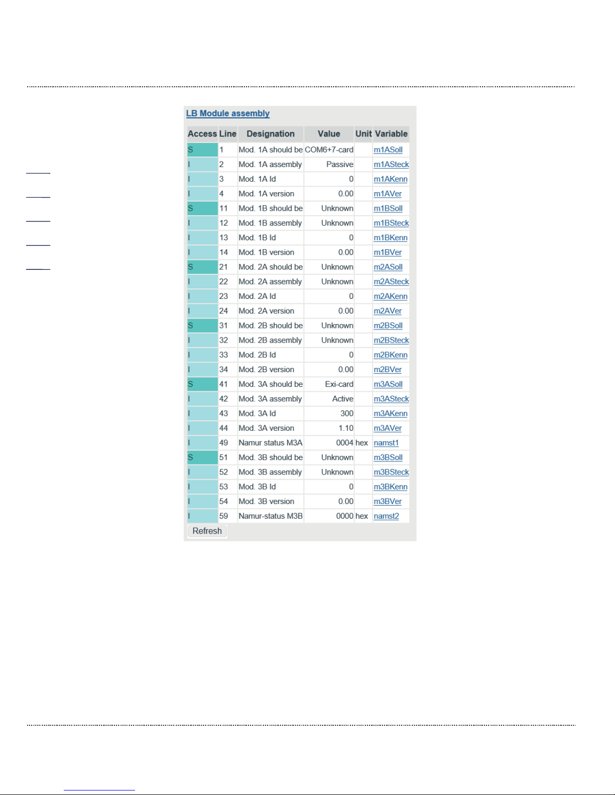
3 ELECTRICAL CONNECTIONS
Manual ERZ2000-DI · EN1.2 · 2017, December 21st
74
Figure 60: Menu LB Module assembly
Device rear wall
Since the ERZ2000-DI has a universal configuration, there are more connection
terminals that required by the typical device (e.g. a status flow computer). There is
a standard assignment of terminals that always use the first pins in consideration
of numbering. Additional pins are reserves and/or can be assigned by means of
software. Therefore, it is also possible to connect the pressure transducer to one
of the free reserve inputs and select it by means of software.
Page 81
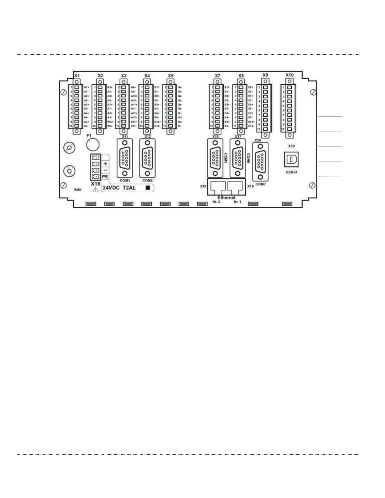
3 ELECTRICAL CONNECTIONS
Manual ERZ2000-DI · EN1.2 · 2017, December 21st
75
Figure 61: Rear wall of the ERZ2000-DI
Page 82

3 ELECTRICAL CONNECTIONS
Manual ERZ2000-DI · EN1.2 · 2017, December 21st
76
3.1.2 Terminal assignment
Connection of supply voltage:
Figure 61: Rear wall of the ERZ2000-DI (bottom left)
X 16
24 V DC
–10% / +15%
Fuse F1 = 2 A
1.0 A
Typical power consumption
(depending on equipment)
24 W
Max. output
ERZ2000-DI without external Ex- separator stage Ex1-NAMUR-2 / V1 or V2
X 1 Terminal 1 Transistor output 1 +
Terminal 2 Transistor output 1 Terminal 3 Transistor output 2 +
Terminal 4 Transistor output 2 Terminal 5 Transistor output 3 +
Terminal 6 Transistor output 3 Terminal 7 Transistor output 4 +
Terminal 8 Transistor output 4 Terminal 9 Alarm contact + semiconductor rel. poled, NC
Terminal 10 Alarm contact – semiconductor rel. poled, NC
X 2 Terminal 1 Transistor output 5 +
Terminal 2 Transistor output 5 Terminal 3 Transistor output 6 +
Terminal 4 Transistor output 6 Terminal 5 Transistor output 7 +
Terminal 6 Transistor output 7 Terminal 7 Frequency output + (higher prio) or transistor output 8 +
Terminal 8 Frequency output - (higher prio) or transistor output 8 Terminal 9 Transistor output Warning message +
Terminal 10 Transistor output Warning message -
X 3 Terminal 1 Pulse output 1 + Dispatcher or meter pulse
Terminal 2 Pulse output 1 - Dispatcher or meter pulse
Terminal 3 Pulse output 2 + Dispatcher or meter pulse
Terminal 4 Pulse output 2 - Dispatcher or meter pulse
Terminal 5 Pulse output 3 + Dispatcher or meter pulse
Terminal 6 Pulse output 3 - Dispatcher or meter pulse
Terminal 7 Pulse output 4 + Dispatcher or meter pulse
Terminal 8 Pulse output 4 - Dispatcher or meter pulse
Terminal 9 Reserve 2nd input for Vo with external separator stage +
Terminal 10 Reserve 2nd input for Vo with external separator stage -
Page 83
3 ELECTRICAL CONNECTIONS
Manual ERZ2000-DI · EN1.2 · 2017, December 21st
77
X 4 Terminal 1 Current output 1 +
Terminal 2 Current output 1 Terminal 3 Current output 2 +
Terminal 4 Current output 2 Terminal 5 Current output 3 +
Terminal 6 Current output 3 Terminal 7 Current output 4 +
Terminal 8 Current output 4 Terminal 9 Input for Vo with external separator stage +
Terminal 10 Input for Vo with external separator stage -
X 5 Terminal 1 Current input 1 active or passive
Terminal 2 Current input 1, active or passive
Terminal 3 Current input 2, active or passive
Terminal 4 Current input 2, active or passive
Terminal 5 Current input 3, active or passive
Terminal 6 Current input 3, active or passive
Terminal 7 PT 100 # 1 supply ++ standard connection
Terminal 8 PT 100 # 1 sense + standard connection
Terminal 9 PT 100 # 1 sense - standard connection
Terminal 10 PT 100 # 1 supply - - standard connection
X 7 Terminal 1 Signal input 1 + , assignment takes place with software
Terminal 2 Signal input 1 - , assignment takes place with software
Terminal 3 Signal input 2 + , assignment takes place with software
Terminal 4 Signal input 2 - , assignment takes place with software
Terminal 5 Signal input 3 + , assignment takes place with software
Terminal 6 Signal input 3 - , assignment takes place with software
Terminal 7 Signal input 4 + , assignment takes place with software
Terminal 8 Signal input 4 - , assignment takes place with software
Terminal 9 Signal input 5 + , assignment takes place with software
Terminal 10 Signal input 5 - , assignment takes place with software
X 8 Terminal 1 Signal input 6 + , assignment takes place with software
Terminal 2 Signal input 6 - assignment takes place with software
Terminal 3 Signal input. 7 + reserve for 2nd vol. input measuring channel
Terminal 4 Signal input 7 - reserve for 2nd vol. input measuring channel
Terminal 5 Signal input 8 + reserve for 2nd vol. input comparison channel
Terminal 6 Signal input 8 - reserve for 2nd vol. input comparison channel
Terminal 7 Volume input measuring channel (HFX) + (external isolation)
Terminal 8 Volume input measuring channel (HFX) - (external isolation)
Terminal 9 Volume input comparison channel (HFY) + (ext. isolation)
Terminal 10 Volume input comparison channel (HFY) - (ext. isolation)
Page 84
3 ELECTRICAL CONNECTIONS
Manual ERZ2000-DI · EN1.2 · 2017, December 21st
78
ERZ2004/2104-DI; X 9 and X 10 are optionally assigned
X 9 Terminal 1 Ex-option enco + (Vo)
Terminal 2 Ex-option enco - (Vo)
Terminal 3 Ex-option Vm measuring channel (HFX) +
Terminal 4 Ex-option Vm measuring channel (HFX) Terminal 5 Ex-option Vm comparison channel (HFY) +
Terminal 6 Ex-option Vm comparison channel (HFX) Terminal 7 Ex-option pressure measurement - transmitter (opt. HART)
Terminal 8 Ex-option pressure measurement + transmitter (opt. HART)
Terminal 9 Ex-option temp. - transmitter (opt. HART) for PT 100 s. X 10
Terminal 10 Ex-option temp. + transmitter (opt. HART) for PT 100 s. X 10
X 10 Terminal 1 reserve / free
Terminal 2 reserve / free
Terminal 3 reserve / free
Terminal 4 reserve / free
Terminal 5 reserve / free
Terminal 6 reserve / free
Terminal 7 Ex-option PT 100 supply ++
Terminal 8 Ex-option PT 100 sense +
Terminal 9 Ex-option PT 100 sense Terminal 10 Ex-option PT 100 supply - -
Note
With use of the internal Ex isolation stage:
A mixture of inputs is possible with respect to Ex protection, which means
an individual signal can also be used with an external isolation stage or
with a
pressure-proof encapsulated
ignition protection type, in combina-
tion with
Ex intrinsically safe protection type.
Example:
The volume inputs for measuring and comparison channels and the original ENCO
meter are operated on X 9 via the internal Ex card, the pressure transducer is operated as a 4..20 mA transmitter and the temperature probe is operated as PT 100
4-wire connection with pressure-proof encapsulation ignition pressure type and
connected to X 5.
Other possible mixtures are feasible.
The number of connection possibilities increases if the optional Ex input card is
used. This input card enables galvanic isolation of MSR signals, such as 20 mA
Page 85
3 ELECTRICAL CONNECTIONS
Manual ERZ2000-DI · EN1.2 · 2017, December 21st
79
current loops or the adjustment and/or standardization of signals. Intrinsically safe
field devices can be operated within explosion-prone areas with the isolation.
For further information, refer to appendix D) Optional Ex input card.
3.1.3 Data interfaces
The digital data interfaces are also provided on the basic assembly. These interfaces can be used as:
x Service interface
x Modbus for external data transmission
x Ethernet TCP/IP network connections
x Connection for an external modem (DSfG-B)
x Serial data interfaces
Interface characteristics
Recommendation / possible use
X 11
COM 1
Interface
Modbus RTU / ASCII
X 12
COM 2
Interface
X 15
COM 5
Interface
External modem, PTB time call-up
X 37
COM 6
Interface
Modbus master for reading the gas
composition and volume
(F-
instance)
X 38
COM 7
Interface
X 18
Ethernet 1
Network connection
Multi-session capability: Modbus IP,
http Single-Session (selectable interface): Remote operation, DSfG
-B-
IP,
SNTP, TIME
X 19
Ethernet 2
Network connection
Page 86
3 ELECTRICAL CONNECTIONS
Manual ERZ2000-DI · EN1.2 · 2017, December 21st
80
3.1.4 Pin assignment and usage recommendation of the inter-
faces
COM 1: Pin assignment
Pin
Mode: RS 232
Mode: RS 422
Mode: RS 485
1
+U (+5V DC)
+U (+5V DC)
+U (+5V DC)
2
RxD
TxD-A
3 TxD
R/TA A Data
4 RxD-A
5
GND
GND
SGND Signal Ground
6 TxD-B
7
8 RxD-B
R/TN B Data
9
Use
Switchable from RS 232 to RS 422 or RS 485, can be optionally assigned with different protocols, MODBUS protocol and IGM (for ultrasonic meters) available.
Optionally, MODBUS ASCII / RTU can be offered as Modbus standard driver for
RS 232 or RS 485 interfaces.
The operating mode for the COM 1 interface is adjusted in the wizard in the menu
IG Serial interfaces with the coordinate IG03 COM 1 operating mode.
COM 2: Pin assignment
Pin
Mode RS 232
1
2
RxD
3
TxD
4
5
GND
6 7
8 9
The operating mode for the COM 2 interface is adjusted in the wizard.
Page 87
3 ELECTRICAL CONNECTIONS
Manual ERZ2000-DI · EN1.2 · 2017, December 21st
81
COM 5 (modem): Pin assignment
Pin
Mode: RS 232
1
DCD
2
RxD
3
TxD
4
DTR
5
GND
6
DSR
7
RTS
8
CTS
9
RI
Use
RS 232 with handshake plus DCD (data carrier detect) plus RI (ring indicator). Usable for MODEM (DFÜ).
With connection of a modem, the COM 5 operating mode "Modem" must be selected in the wizard.
3.1.5 External modem connection
The COM 5 interface is used for connection.
Example for a setting
The following setup must be made in the menu GD DSFG instance remote data
transmission:
GD13 Modem init. string ate0s0=1
GD14 Dial prefix atx3dt
Page 88
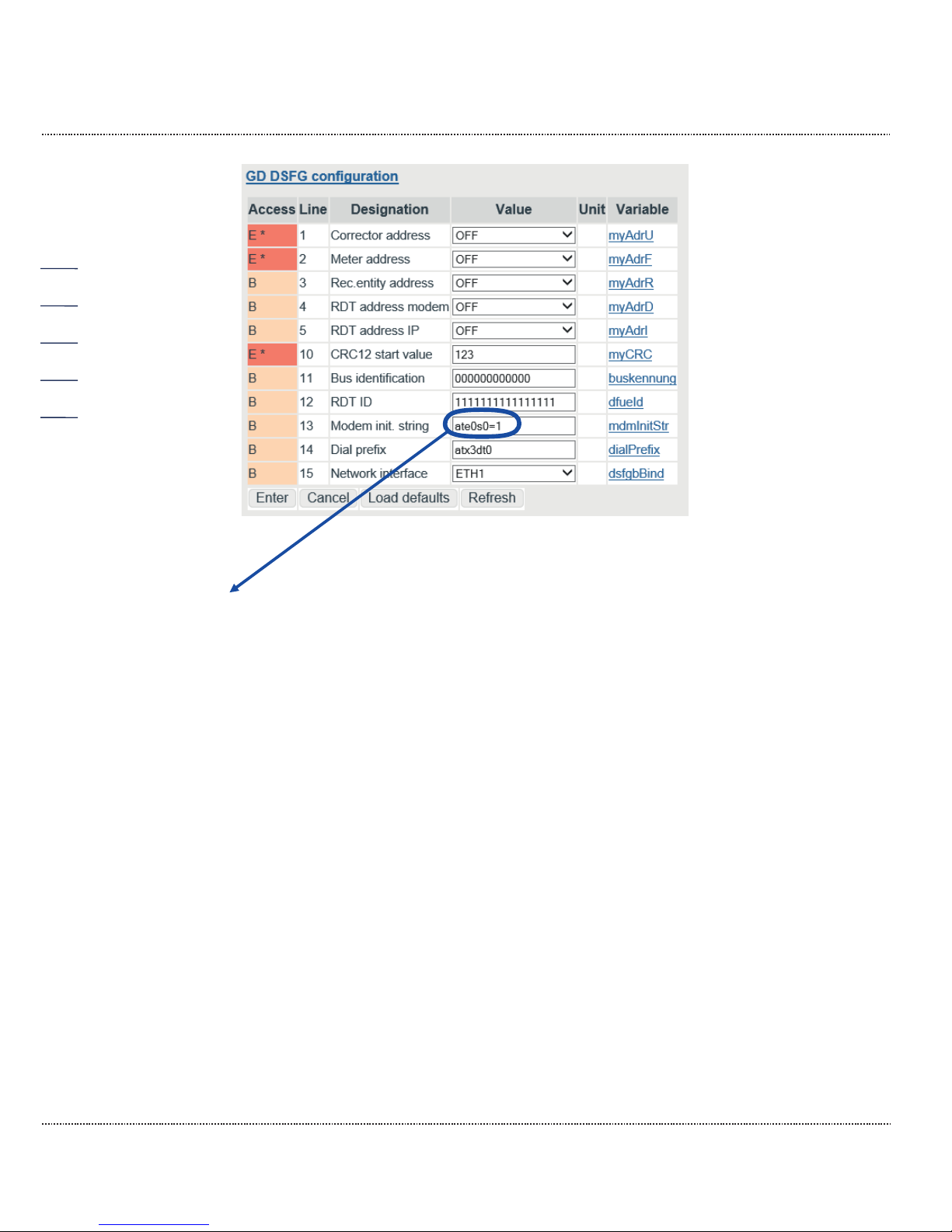
3 ELECTRICAL CONNECTIONS
Manual ERZ2000-DI · EN1.2 · 2017, December 21st
82
Figure 62: DSfG setting
Meaning:
at Prefix of a command line
e0 Echo function deactivated
s0=1 Set register 0 to 1, which means the number of alert characters after
which the modem answers and establishes the connection, should be 1.
x3 Response setting:
Hayes Smartmode 300 compatible answers / blind dialing (extension)
plus all CONNECT answers
plus recognition of busy symbols
dt sound selection process (dp = pulse selection process)
Depending on the modem, there may be other commands, which are covered in
the manufacturer's manual.
Additional settings in the menu IG Serial interfaces:
Page 89
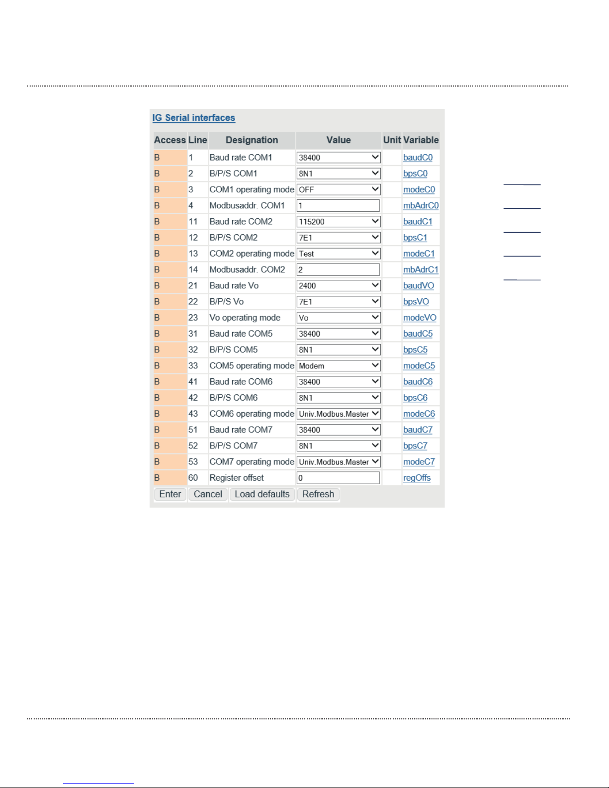
3 ELECTRICAL CONNECTIONS
Manual ERZ2000-DI · EN1.2 · 2017, December 21st
83
Figure 63: Menu: IG Serial interfaces
The parameters for operation of the serial interfaces (also DSfG-B and Modbus)
are adjusted in this menu IG Serial interfaces.
The coordinate IG23 is an internal interface that can be used for the original Vo
totalizer of an encoder (ENCO).
The register offset for the Modbus register is adjusted in IG60. The Modbus address for COM 1 can be entered with IG04 (IG14 for COM 2).
With IG33, COM 5 can be configured for modem connection for "Modem" or "Dedicated line" (with external modem), e.g. DFÜ for DSfG-B.
Page 90

3 ELECTRICAL CONNECTIONS
Manual ERZ2000-DI · EN1.2 · 2017, December 21st
84
3.1.6 Connections
3.1.6.1 Input characteristics
2-channel HF volume flow input with pulse metering and frequency measurement
The appropriate frequency input must be selected in this menu; Inputs 5, 6, 7 and
8 offer higher resolution.
Channel 1: Volume measuring channel HF input
Measuring range
0.10 Hz to 6.0 kHz
Accuracy
0.01 Hz
U hys
1.0 V
U trg
3.0 V
Overvoltage protection
6.8 V with external module
18.0 V with internal module (galvanically isolated)
Channel 2: Volume comparison channel HF input
Same data as for Channel 1
2-channel LF volume flow input with pulse metering and frequency measure-
ment
Channel 1: Volume measuring channel LF input
Measuring range
0.00 Hz to 6.0 kHz
Accuracy
0.01 Hz
U hys
1.0 V
U trg
3.0 V
Overvoltage protection
6.8 V with external module
18.0 V with internal module (galvanically isolated)
Channel 2: Volume comparison channel LF input
Same data as for Channel 1
Volume input for digitally operating Vo totalizer
Data transmission between the gas volume meter and flow computer take place
unidirectionally and reactionless via a shielded, twisted pair of wires from the meter to the flow computer. The electrical characteristic data conforms to DIN 19234
(NAMUR).
Page 91

3 ELECTRICAL CONNECTIONS
Manual ERZ2000-DI · EN1.2 · 2017, December 21st
85
Up to 5 analogue inputs, including a pressure measurement input for analog
signals and for HARD protocol
Current measurement
Range
0/4 to 25 mA
Resolution
20 bit
U max
2.5 V
Ri
250 Ω
Tk
< 15 ppm
Measuring time
50 ms
Overvoltage protection
6.8 V
Calibration of current inputs takes place at the factory, but correction can take
place with the adjustment of the input variables pressure, temperature, etc.
HART protocol connection SMART transmitter (optional)
Two-wire system
Communication
Simultaneously analog and digital
Protocol
HART master
Inputs
3 (optionally 6)
With EX isolation card
(optional)
+ 2 inputs
Distribution of inputs
1 x pressure (reserved)
1 x temperature (reserved)
Remainder -> Free availability
Up to 2 resistor inputs, a temperature measuring input for resistance measurement
Resistance measurement
Type
PT 100 four-wire
Range
-20°C to +60°C
Resolution
0.01°C
Accuracy
0.05°C
Measuring time
50 ms
8 signal inputs for H/L gas switching, travel direction reversal and external
freeze
Page 92

3 ELECTRICAL CONNECTIONS
Manual ERZ2000-DI · EN1.2 · 2017, December 21st
86
Digital status inputs
All inputs are galvanically isolated from the computer, but not from each other. The
following can be used as signal transmitters: contact, open collector / drain, active
push / pull
-U max
5 V
-I max
13 mA
f max
10 Hz
Overvoltage protection
6.8 V
3.1.6.2 Output characteristics
Current outputs
Quantity
4
Range
0-20 mA or 4-20 mA
Resolution
12 bit
Ohmic resistance
700 Ω
Overvoltage protection
from 33 V, galvanically isolated
Signal outputs
Quantity
8
U max
24 V DC
P max
150 mW
Ic max
100 mA
UCEsat
1.2V or Ron = 50 Ohm
F max
400 Hz
Overvoltage protection
33 V, galvanically isolated
Pulse outputs
Quantity
4
tmin off
16 ms
tmax off
230 ms
tmin on
16 ms
tmax on
230 ms
Ic
100 mA
UCEsat
1.2V
F max
400 Hz
Overvoltage protection
33 V, galvanically isolated
Page 93

3 ELECTRICAL CONNECTIONS
Manual ERZ2000-DI · EN1.2 · 2017, December 21st
87
Alarm and warning status outputs
U max
24 V DC
I max
100 mA
P max
100 mW
RDSon
<= 50 Ohm
Photomos relay
Ic
100 mA
Ron
50 Ohm
Overvoltage protection
33 V, galvanically isolated
3.1.7 Assignment of "physical values"
The assignment of inputs and outputs to "physical values" takes place in the
wizard.
Page 94
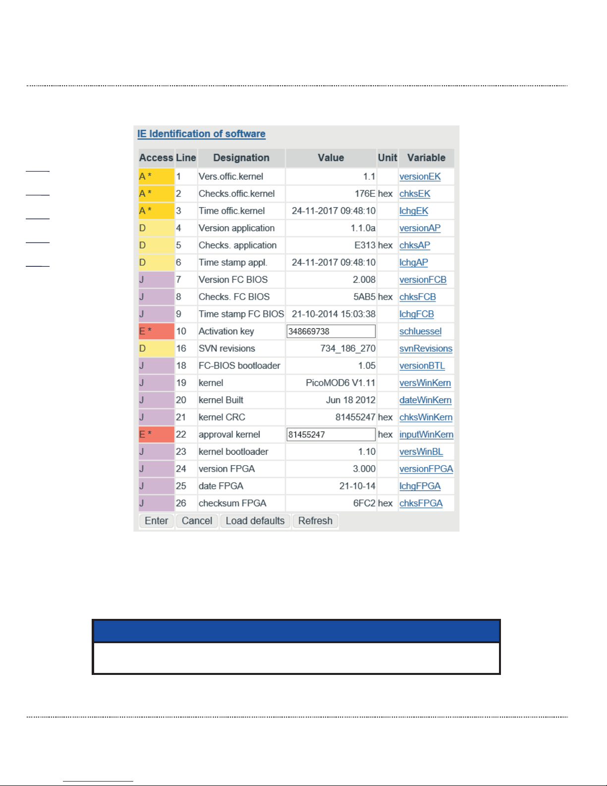
3 ELECTRICAL CONNECTIONS
Manual ERZ2000-DI · EN1.2 · 2017, December 21st
88
3.1.8 Software and hardware identification
Figure 64: Menu IE Software identification
There is an additional microcontroller on the base circuit board for control of the
FPGA and basic measuring functions whose program is monitored with a check
number.
Note
This check number is a component of the custody transfer approval.
Page 95

3 ELECTRICAL CONNECTIONS
Manual ERZ2000-DI · EN1.2 · 2017, December 21st
89
The check number must be entered in coordinate IE10 Activation key. The Activation key can be found in the approval documents under "Identification".
The kernel has a Target check, which can also be found in the approval documentation and must be entered. This appropriate actual check number is calculated by the ERZ2000-DI with the WinCE operating system and displayed in IE 21.
These check numbers are compared with each other continuously. If there is a de-
viation, the ERZ2000-DI issues an alarm with the message "A57-7 WinCE kernel
CRC false".
Figure 65: Menu LD Identification of hardware
Manufacturer-independent identification numbers for measuring devices (Object
Identification System) are provided in coordinate LD14 OBIS-ID. The OBIS-ID
consists of 4 groups of 4 numbers each. The groups are separated by a blank
space for easier legibility.
SHHH BBFF FFFF FFFF
S: Column (7 = gas)
HHH: Manufacturer (061 = RMG)
BB: Year of manufacture (2-digit, e.g. 13=2013)
FFFFFFFFFF: Serial number (10-digit, only numbers)
The OBIS-ID cannot be edited directly and is generated automatically from the existing coordinates LD02 Year of construct. and LD03 Factory number. Since the
serial number in the ERZ2000-DI is a 20-character-long text field that is already
used, there is generally a combination of numbers and letters in the field. The
number may also be structured, e.g. "RMG-123/456/789". The software ignores all
non-numerical characters when generating the number and the numbers are left in
order. If the remainder number has less than 10 digits, leading zeros are shown. If
the number has more than 10 digits, the highest-order are truncated.
Page 96
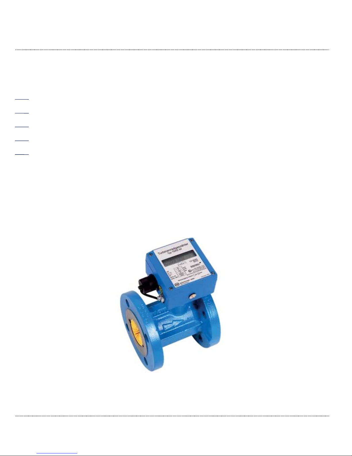
4 TRANSMITTERS
Manual ERZ2000-DI · EN1.2 · 2017, December 21st
90
4 Transmitters
Various transmitters with various connections and communications can be connected to the ERZ2000-DI and bus connections. This normally takes place via the
wizard and supports pre-settings that often only have to be acknowledged.
4.1 Flow meters
Basically, the ERZ2000-DI can work with all flow measuring devices that are used
in the flow measurement of gas.
4.1.1 Turbine wheel gas meters
The operating method of turbine wheel gas meters is based on the measurement
of gas speed with a turbine wheel. In the process, the speed of the turbine (approximately) within the measuring range (Q
min - Qmax) is proportional to the mean
gas speed and thus the flow rate. The number of rotations, therefore, is a measurement for the gas volume flowing through.
Figure 66: RMG turbine wheel gas meter TERZ94
Page 97

4 TRANSMITTERS
Manual ERZ2000-DI · EN1.2 · 2017, December 21st
91
Figure 67: RMG turbine gas wheel meter sectional drawing
The rotational movement of the turbine wheel is transferred after reduction to the
meter head in which the frequency is normally scanned redundantly with two sensors and transmitted as a LF signal. The meter can be optionally equipped with an
encoder that can also transmit flow information.
In principle, the further processing of low-frequency pulses independently of the
measuring principle, can also be handled in a comparable manner by rotary piston
gas meters, vortex meters or other flow measuring devices with a frequency output.
Page 98
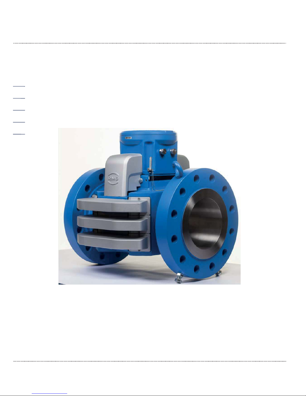
4 TRANSMITTERS
Manual ERZ2000-DI · EN1.2 · 2017, December 21st
92
4.1.2 Ultrasonic gas meters
Ultrasonic gas meters use the physical principle for volume flow detection that an
ultrasonic pulse in the flow direction (with the flow) spreads faster than the opposite. With run-time measurement of ultrasonic pulses between appropriately arranged ultrasonic transducers, a flow speed and thus the flow rate can be determined. To achieve greater accuracy, multiple ultrasonic transducer pairs are nor-
mally used over multiple measuring paths. Figure 68: RMG ultrasonic gas meter
USM-GT400 shows an ultrasonic gas meter from RMG and Figure 69: Measuring
path arrangement USM-GT400 shows the basic arrangement of ultrasonic trans-
ducers with the measuring path.
Figure 68: RMG ultrasonic gas meter USM-GT400
Page 99
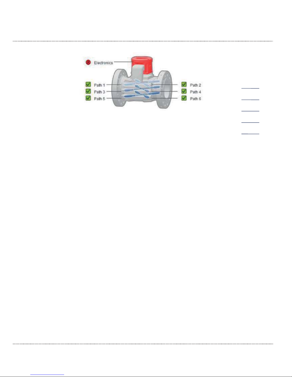
4 TRANSMITTERS
Manual ERZ2000-DI · EN1.2 · 2017, December 21st
93
Figure 69: Measuring path arrangement USM-GT400
Page 100
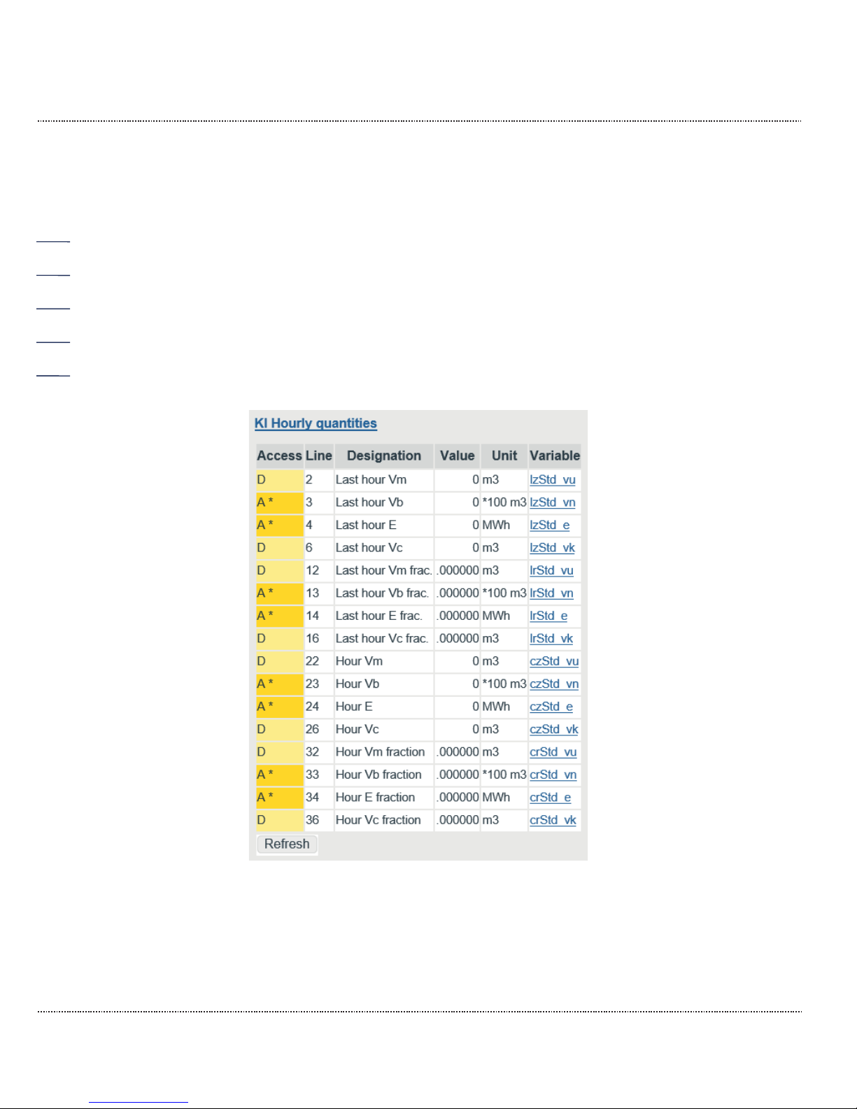
5 SPECIAL COORDINATES
Manual ERZ2000-DI · EN1.2 · 2017, December 21st
94
5 Special coordinates
Interim results of the highest load determination are shown in the hourly and daily
amount menus. In case of faults, they behave as defined by the approval authorities. For a user who intends to base billing on these figures, the values cannot be
used in case of a malfunction or are at least misleading.
Additional menus shown here include Documentation, Parameterization, Parameter aids, and Miscellaneous.
5.1.1 KI Hourly quantities
Figure 70: Menu KI Hourly amounts
Menus KI Hourly quantities and KJ Daily quantities are purely visualization
menus. The amounts of the last hour KI02...KI16 are represented in the
Documentation / Documentation / Modbus Register 1400...1428.
 Loading...