


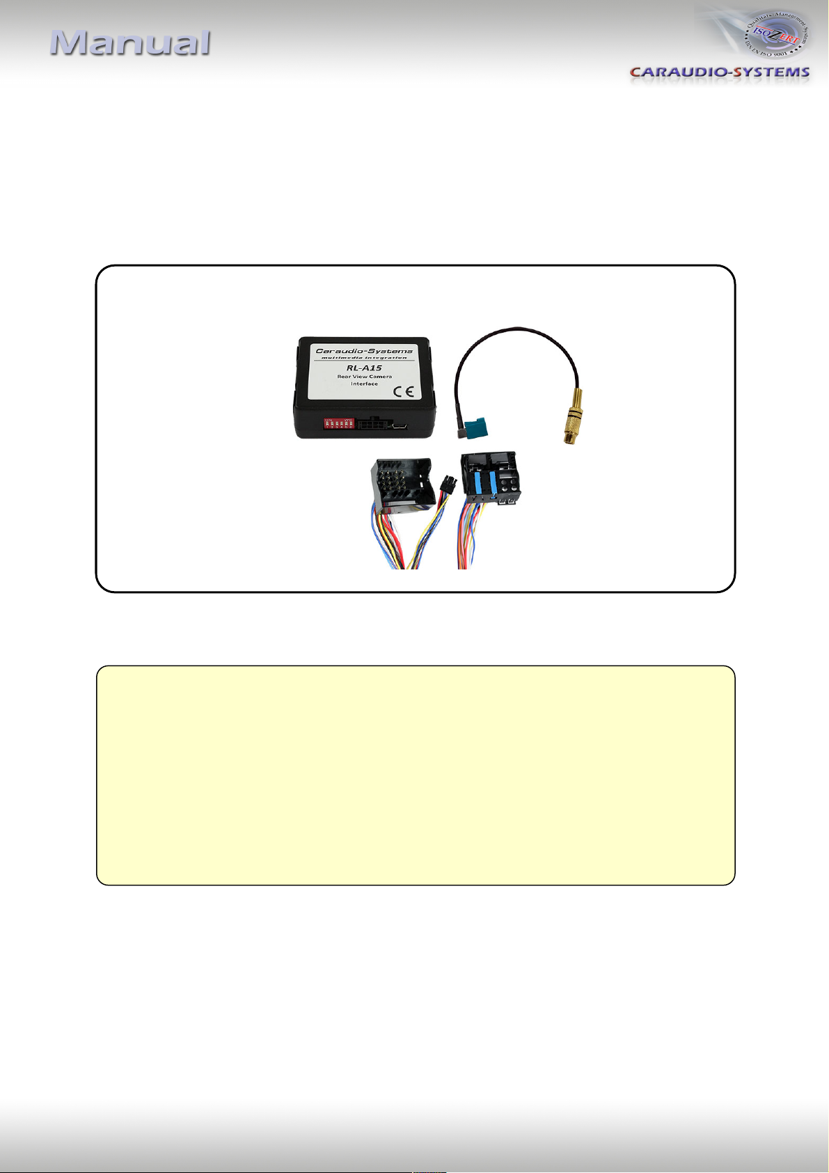
r.LiNK-Interface
RL-A15
Rear view camera input
compatible with Mercedes Vito
Audio15 system
Version 19.08.2020 RL-A15

Page
1
"
Contents
1. Prior to installation
1.1. Delivery contents
1.2. Check compatibility of vehicle and accessories
1.3. Setting the Dip-switches of the CAN-Box RLC-TV515
1.4. Pin-assignments
2. Connection schema
3. Installation
3.1. Interconnecting CAN-box, harness and factory navigation monitor
3.2. Connection to rear-view camera
4. Coding of the rear-view camera
4.1. Rear-view camera coding
4.2. Rear-view camera decoding
5. Speed related rear view camera shut down
6. Specifications
7. Technical support
Legal Information
By law, watching moving pictures while driving is prohibited, the driver must not be
distracted. We do not accept any liability for material damage or personal injury resulting,
directly or indirectly, from installation or operation of this product. This product should only
be used while standing or to display fixed menus or rear-view-camera video when the
vehicle is moving, for example the MP3 menu for DVD upgrades.
Changes/updates of the vehicle’s software can cause malfunctions of the interface. We
offer free software-updates for our interfaces for one year after purchase. To receive a free
update, the interface must be sent in at own cost. Labor cost for and other expenses
involved with the software-updates will not be refunded.
Version 19.08.2020 RL-A15
Page
2
"
CAN-box RLC-TV515
HW_____ SW_____
Take down the SW-version and HW-version of the interface boxes, and store this
manual for support purposes.
Adapter
CAB-TVAS20A
Requirements
Vehicle Mercedes Vito (W447)
Navigation Audio15
Limitations
After-market rear-view Only compatible with NTSC-cameras.
camera
Harness
TV-NTG2
1. Prior to installation
Read the manual prior to installation. Technical knowledge is necessary for installation. The
place of installation must be free of moisture and away from heat sources.
1.1. Delivery contents
1.2. Check compatibility of vehicle and accessories
Version 19.08.2020 RL-A15

Page
3
"
Vehicle/ navigation
Dip 1
Dip 2
Dip 3
Dip 4
Dip 5
Dip 6
Camera coding
ON
OFF
OFF
OFF
OFF
ON
Camera decoding
OFF
OFF
OFF
OFF
OFF
ON
1.3. Setting the dip switches of the CAN-box RLC-TV515
Note: Dip switch functions of the RLC-TV515
Dip 1 – Camera coding
Dip 2 – Speed related rear view camera shut down
Dip 3 – no function
Dip 4 – no function
Dip 5 – CAN-bus termination resistor on the vehicle side
Dip 6 – CAN-bus termination resistor on the head-unit side
Version 19.08.2020 RL-A15

Page
4
"
Cable colour
Pin-No.
Assignment
● Yellow
Pin 4
CAN-HIGH – connection to the head-unit
● Blue
Pin 3
CAN-LOW – connection to the head-unit
●● Yellow/Black
Pin 8
CAN-HIGH – connection to the vehicle
●● Blue/Black
Pin 7
CAN-LOW – connection to the vehicle
● Red
Pin 1
+12V permanent
● Black
Pin 5
Ground
● Green
Pin 6
No function
● White
Pin 2
+12V rear view camera (max. 400mA)
Assignment
Pin No.
+12V battery
Pin 15
Ground
Pin 12
CAN-low
Pin 9
CAN-high
Pin 11
1.4. Pin-assignments
Pin-assignment factory connector
No liability for vehicle wire colors and pin definition! Possible changes by the vehicle
manufacturer. The given information must be verified by the installer.
Pin-assignment of the CAN-Box RLC-TV515 (Molex 8pin)
Version 19.08.2020 RL-A15

Page
5
"
!"#$%&'($ )*+ ,
-./0123 4 3
56'78+(9 &$:'8$
;$<=(8$ <'%"$>>
?'%"$>>
120@1AB
@+ &6"(#=+"
C4B 2)(':$%'
+6#D6#
E:',F) G H H:IJ
-$'% >=7$ +&
<$'7 +"=#
Rea r view
camera
/IK012ILB H I
2. Connection schema
Version 19.08.2020 RL-A15

Page
6
"
Interface )bo x
RLC-TV5 1 5
Quadloc k female
vehicle harness
Harness
TV-NTG2
Rear side of
head onit
1
2
3
4
2
1
3. Installation
Switch off ignition and disconnect the vehicle’s battery! If according to factory rules
disconnecting the battery has to be avoided, it is usually sufficient to put the vehicle in
sleep-mode. In case the sleep-mode does not show success, disconnect the battery with a
resistor lead.
Place of installation is on rear of the head unit.
3.1. Interconnecting CAN-Box, harness and factory head unit
Connect female 8pin Molex connector of harness TV-NTG2 to male 8pin Molex
connector of CAN-box RLC-TV515.
Remove the female Quadlock connector of the vehicle harness from the rear of the
head unit and connect it to the male Quadlock connector of harness TV-NTG2.
Version 19.08.2020 RL-A15

Page
7
"
Rear side of
head onit
Rea r view
camera
CAB-TVAS2 0 A
Harness
TV-NTG2
+12 V;camera
output
(max.; 4 0 0 mA)
1
2
3
2
1
3 3 4
Remove the 12pin Quadlock plug inserts from the female Quadlock connector of the
vehicle harness and insert them into the female Quadlock connector of harness
TV-NTG2 at the same position.
Connect female Quadlock connector of harness TV-NTG2 to the male Quadlock
connector of the head unit.
Note: The loose green cable is not required and must be isolated.
3.2. Connections to rear-view camera
Connect the video RCA of the rear-view camera to the female RCA connector of
adapter CAB-TVAS20A.
Connect the Fakra socket of adapter CAB-TVAS20A to the green Fakra connector on
the rear of the head unit.
Connect the white cable of harness TV-NTG2 to the camera power supply (+12V,
max 400mA). The white cable gets power when reverse gear is engaged. By leaving
the rear camera level the power is switch off again
Note: Only compatible with NTSC-cameras.
Version 19.08.2020 RL-A15

Page
8
"
Dip 1
Dip 2
Dip 3
Dip 4
Dip 5
Dip 6
ON
ON
OFF
OFF
OFF
ON
LED
Status
Explication
Blue
Lights
CAN bus communication OK
Flashes
CAN bus search
Red
Lights
Rear-view camera is coded
Off
Rear-view camera is not coded
4. Coding of the rear-view camera
4.1. Rear-view camera coding
1. Set DIP switch „1“ and “6“ to „ON“ (DIP 2,3,4,5 = OFF)
2. Turn ignition on (ignition position 2, Note: Do not start engine)
3. Wait until the Audio15 device has booted
4. Insert reverse gear („Diag“ appears on the screen and after a short time, the Audio15
device goes off)
5. Turn on the Audio15 device manually (press ON button)
6. The coding process is now complete
Note: When after the coding process the camera function is still not activated (red
LED on the interface remains off), then additionally the ignition must be switched off
and the vehicle must be locked for approx. 5 min.
4.2. Rear-view camera decoding
1. Set DIP switch “6“ to „ON“, “1” to OFF (DIP 1,2,3,4,5 = OFF)
2. Turn ignition on (ignition position 2, Note: Do not start engine)
3. Wait until the Audio15 device has booted
4. Insert reverse gear („Diag“ appears on the screen and after a short time, the Audio15
device goes off)
5. Turn on the Audio15 device manually (press ON button)
6. The decoding process is now complete
LED information:
Note: After the first use on a vehicle, the RL-A15 interface is personalized to this vehicle and
can be used unlimited times to code or reverse coding on this vehicle.
5. Speed related rear view camera shut down
Dip 2 switch „ON“*: Rear view camera automatically switches off at 20 km/h
Dip 2 switch „OFF“: Rear view camera switch off when reverse gear is disengaged
*Note: Rear view camera can also be manually switched off via the Audio15 system
Version 19.08.2020 RL-A15

Page
9
"
6. Specifications
Operation voltage 10.5 – 14.8V
Stand-by power drain <2mA
Operation power drain ~60mA
Power consumption ~0,08W
Temperature range -30°C to +80°C
Weight 44g
Measurements (box only) W x H x D 70 x 20 x 47 mm/ 76 x 27 x 54 mm
7. Technical support
Caraudio-Systems Vertriebs GmbH
manufacturer/distribution
In den Fuchslöchern 3
D-67240 Bobenheim-Roxheim
Legal disclaimer: Mentioned company and trademarks, as well as product names/codes are registered
trademarks ® of their corresponding legal owners.
email support@caraudio-systems.de
Version 19.08.2020 RL-A15
 Loading...