


Monitoring
F110 User Guide

Copyright Notice
©2010 RLE Technologies. All rights reserved. No part of this publication may be reproduced or
distributed in any form or by any means, or stored in a database or retrieval system, without the
prior written permission of RLE Technologies.
Trademark Notices
RLE is a registered trademark and Falcon, Raptor, and SeaHawk are trademarks of RLE
Technologies. All other trademarks or registered trademarks are the property of their respective
companies.
Revision History
Part number 11056
Rev. No. Date
2.0 June 2010
Note: As necessary, blank pages are added to make the page count even.
rletech.com 2 970.484.6510

Product Registration
Product registration helps RLE Technologies inform owners of:
• Product upgrades
• Firmware enhancements
• New products and technologies
• Special offers available only to registered users
Access and submit Product Registration information from the F110 Configuration Menu.
Any information provided to RLE Technologies through the registration form will be regarded as
confidential. RLE will not sell or distribute any of the information to third parties. To read our
Privacy Policy, please visit our website: www.rletech.com.
Technical Support
Personal assistance is available Monday through Friday, from 8:00 a.m. to 5:00 p.m. MST.
A request for assistance may be sent to support@rletech.com.
Otherwise, please call us directly at: (970) 484-6510, and press “2” for technical support.
The following information is located on the bottom of each F110 unit. Please have this information
available whenever a technical support call is placed:
Product Model Number
Product Serial Number
Product Manufacture Date
970.484.6510 3 rletech.com

Notes:
rletech.com 4 970.484.6510

Contents
1 System Overview . . . . . . . . . . . . . . . . . . . . . . . . . . . . . . . . . . . . . . . . . . . . . . . . 11
Product Description. . . . . . . . . . . . . . . . . . . . . . . . . . . . . . . . . . . . . . . . . . . . . . . . . . . . . . . . . . . . . 11
Front Panel Indicators and Controls . . . . . . . . . . . . . . . . . . . . . . . . . . . . . . . . . . . . . . . . . . . . . . . . 12
Terminal Block Designations. . . . . . . . . . . . . . . . . . . . . . . . . . . . . . . . . . . . . . . . . . . . . . . . . . . . . . 13
2 Getting Started . . . . . . . . . . . . . . . . . . . . . . . . . . . . . . . . . . . . . . . . . . . . . . . . . . 15
Installation . . . . . . . . . . . . . . . . . . . . . . . . . . . . . . . . . . . . . . . . . . . . . . . . . . . . . . . . . . . . . . . . . . . . 15
Communication . . . . . . . . . . . . . . . . . . . . . . . . . . . . . . . . . . . . . . . . . . . . . . . . . . . . . . . . . . . . . . . . 15
Search . . . . . . . . . . . . . . . . . . . . . . . . . . . . . . . . . . . . . . . . . . . . . . . . . . . . . . . . . . . . . . . . . . 16
Set IP . . . . . . . . . . . . . . . . . . . . . . . . . . . . . . . . . . . . . . . . . . . . . . . . . . . . . . . . . . . . . . . . . . . 16
IP Address Assignment for Static Only Networks . . . . . . . . . . . . . . . . . . . . . . . . . . . . . . . . . 16
Settings . . . . . . . . . . . . . . . . . . . . . . . . . . . . . . . . . . . . . . . . . . . . . . . . . . . . . . . . . . . . . . . . . 16
Web . . . . . . . . . . . . . . . . . . . . . . . . . . . . . . . . . . . . . . . . . . . . . . . . . . . . . . . . . . . . . . . . . . . . 16
Update . . . . . . . . . . . . . . . . . . . . . . . . . . . . . . . . . . . . . . . . . . . . . . . . . . . . . . . . . . . . . . . . . . 17
F110 Wiring. . . . . . . . . . . . . . . . . . . . . . . . . . . . . . . . . . . . . . . . . . . . . . . . . . . . . . . . . . . . . . . . . . . 17
Power Supply . . . . . . . . . . . . . . . . . . . . . . . . . . . . . . . . . . . . . . . . . . . . . . . . . . . . . . . . . . . . . 17
RJ45 Ethernet Connection . . . . . . . . . . . . . . . . . . . . . . . . . . . . . . . . . . . . . . . . . . . . . . . . . . . 18
3 F110 Web Interface . . . . . . . . . . . . . . . . . . . . . . . . . . . . . . . . . . . . . . . . . . . . . . . 19
F110 Web Interface Overview. . . . . . . . . . . . . . . . . . . . . . . . . . . . . . . . . . . . . . . . . . . . . . . . . . . . . 19
Status Screen . . . . . . . . . . . . . . . . . . . . . . . . . . . . . . . . . . . . . . . . . . . . . . . . . . . . . . . . . . . . . . . . . 19
Settings Screen. . . . . . . . . . . . . . . . . . . . . . . . . . . . . . . . . . . . . . . . . . . . . . . . . . . . . . . . . . . . . . . . 20
Network . . . . . . . . . . . . . . . . . . . . . . . . . . . . . . . . . . . . . . . . . . . . . . . . . . . . . . . . . . . . . . . . . 21
Email . . . . . . . . . . . . . . . . . . . . . . . . . . . . . . . . . . . . . . . . . . . . . . . . . . . . . . . . . . . . . . . . . . . 22
SNMP. . . . . . . . . . . . . . . . . . . . . . . . . . . . . . . . . . . . . . . . . . . . . . . . . . . . . . . . . . . . . . . . . . . 23
Channel 2, Channel 3 and Channel 4 . . . . . . . . . . . . . . . . . . . . . . . . . . . . . . . . . . . . . . . . . . 24
External Temperature/Humidity . . . . . . . . . . . . . . . . . . . . . . . . . . . . . . . . . . . . . . . . . . . . 24
Switched Sensor Alarm Configuration . . . . . . . . . . . . . . . . . . . . . . . . . . . . . . . . . . . . . . . . . . 25
Security . . . . . . . . . . . . . . . . . . . . . . . . . . . . . . . . . . . . . . . . . . . . . . . . . . . . . . . . . . . . . . . . . 25
Advanced . . . . . . . . . . . . . . . . . . . . . . . . . . . . . . . . . . . . . . . . . . . . . . . . . . . . . . . . . . . . . . . . 26
Reset Defaults . . . . . . . . . . . . . . . . . . . . . . . . . . . . . . . . . . . . . . . . . . . . . . . . . . . . . . . . . . . . 27
Help Screen . . . . . . . . . . . . . . . . . . . . . . . . . . . . . . . . . . . . . . . . . . . . . . . . . . . . . . . . . . . . . . 28
About Screen . . . . . . . . . . . . . . . . . . . . . . . . . . . . . . . . . . . . . . . . . . . . . . . . . . . . . . . . . . . . . 28
A Modbus Configuration Via Telnet . . . . . . . . . . . . . . . . . . . . . . . . . . . . . . . . . . . 29
F110 Modbus Capabilities. . . . . . . . . . . . . . . . . . . . . . . . . . . . . . . . . . . . . . . . . . . . . . . . . . . . . . . . 29
Telnet Configuration . . . . . . . . . . . . . . . . . . . . . . . . . . . . . . . . . . . . . . . . . . . . . . . . . . . . . . . . . . . . 29
B Modbus Registers . . . . . . . . . . . . . . . . . . . . . . . . . . . . . . . . . . . . . . . . . . . . . . . . 31
C Technical Specifications . . . . . . . . . . . . . . . . . . . . . . . . . . . . . . . . . . . . . . . . . . 35
rletech.com 5 970.484.6510

Notes:
970.484.6510 6 rletech.com

Figures
1 System Overview . . . . . . . . . . . . . . . . . . . . . . . . . . . . . . . . . . . . . . . . . . . . . . . . 11
Figure 1.1 F110 Font Panel Indicators and Controls . . . . . . . . . . . . . . . . . . . . . . . . . . . 12
Figure 1.2 F110 Terminal Block Designations . . . . . . . . . . . . . . . . . . . . . . . . . . . . . . . . 13
2 Getting Started . . . . . . . . . . . . . . . . . . . . . . . . . . . . . . . . . . . . . . . . . . . . . . . . . . 15
Figure 2.1 Device Discovery Utility . . . . . . . . . . . . . . . . . . . . . . . . . . . . . . . . . . . . . . . . . 15
Figure 2.2 IP Pop-up Box . . . . . . . . . . . . . . . . . . . . . . . . . . . . . . . . . . . . . . . . . . . . . . . . 16
Figure 2.3 5VDC Power Supply Connection. . . . . . . . . . . . . . . . . . . . . . . . . . . . . . . . . . 17
Figure 2.4 Physical Connection . . . . . . . . . . . . . . . . . . . . . . . . . . . . . . . . . . . . . . . . . . . 18
Figure 2.5 F110 Ethernet Connection to a PC on a Subnet . . . . . . . . . . . . . . . . . . . . . . 18
3 F110 Web Interface . . . . . . . . . . . . . . . . . . . . . . . . . . . . . . . . . . . . . . . . . . . . . . 19
Figure 3.1 F110 Status Screen. . . . . . . . . . . . . . . . . . . . . . . . . . . . . . . . . . . . . . . . . . . . 19
Figure 3.2 Authentication Security Prompt (no Username or Password) . . . . . . . . . . . . 20
Figure 3.3 Network Settings . . . . . . . . . . . . . . . . . . . . . . . . . . . . . . . . . . . . . . . . . . . . . . 21
Figure 3.4 Email Settings . . . . . . . . . . . . . . . . . . . . . . . . . . . . . . . . . . . . . . . . . . . . . . . . 22
Figure 3.5 SNMP Settings . . . . . . . . . . . . . . . . . . . . . . . . . . . . . . . . . . . . . . . . . . . . . . . 23
Figure 3.6 Sensor Settings . . . . . . . . . . . . . . . . . . . . . . . . . . . . . . . . . . . . . . . . . . . . . . . 25
Figure 3.7 Security Settings . . . . . . . . . . . . . . . . . . . . . . . . . . . . . . . . . . . . . . . . . . . . . . 26
Figure 3.8 Advanced Settings. . . . . . . . . . . . . . . . . . . . . . . . . . . . . . . . . . . . . . . . . . . . . 26
Figure 3.9 Restore Defaults Prompt . . . . . . . . . . . . . . . . . . . . . . . . . . . . . . . . . . . . . . . . 27
Figure 3.10 Help Screen . . . . . . . . . . . . . . . . . . . . . . . . . . . . . . . . . . . . . . . . . . . . . . . . . . 28
Figure 3.11 About Screen . . . . . . . . . . . . . . . . . . . . . . . . . . . . . . . . . . . . . . . . . . . . . . . . . 28
A Modbus Configuration Via Telnet . . . . . . . . . . . . . . . . . . . . . . . . . . . . . . . . . . . 29
Figure A.1 Telnet Connection . . . . . . . . . . . . . . . . . . . . . . . . . . . . . . . . . . . . . . . . . . . . 29
rletech.com 7 970.484.6510

Notes:
rletech.com 8 970.484.6510

Tables
B Modbus Registers . . . . . . . . . . . . . . . . . . . . . . . . . . . . . . . . . . . . . . . . . . . . . . . 31
Table B.1 Read Output Registers . . . . . . . . . . . . . . . . . . . . . . . . . . . . . . . . . . . . . . . . . 31
Table B.2 Family Code (Register 40002, 40009, 40016, 40023: FC) . . . . . . . . . . . . . . 32
Table B.3 Status Flags (Register 40003: SS) . . . . . . . . . . . . . . . . . . . . . . . . . . . . . . . . 32
Table B.4 Status Flags (Register 40004: SC) . . . . . . . . . . . . . . . . . . . . . . . . . . . . . . . . 33
Table B.5 Status Flags (Register 40005: AS) . . . . . . . . . . . . . . . . . . . . . . . . . . . . . . . . 33
C Technical Specifications . . . . . . . . . . . . . . . . . . . . . . . . . . . . . . . . . . . . . . . . . 35
Table C.1 Technical Specifications . . . . . . . . . . . . . . . . . . . . . . . . . . . . . . . . . . . . . . . . 35
rletech.com 9 970.484.6510

Notes:
970.484.6510 10 rletech.com

1.1. Product Description
The F110 Monitoring System is a comprehensive system which provides equipment protection
by monitoring critical operating parameters in enterprises, remote network facilities,
communication rooms, and critical support systems. The F110 is a stand alone system. It
operates via embedded “firmware” that handles all data collection, alarm reporting, and
multiple concurrent communication mediums.
C HAPTER
CHAPTER 0SYSTEM OVERVIEW
The F110 is designed specifically to monitor any combination of 3 digital temperature/humidity
sensors or 3 digital temperature only sensors and up to 8 dry contact sensors (signal quality
contacts) that can be distributed at locations spanning up to 100 feet (30m).
Additionally, the F110 allows alert notifications to be sent via email to devices like computers,
phones, pagers and PDAs. Users can set up thresholds for temperatures and humidity as well as
configure monitoring of Normally Open (N/O) or Normally Closed (N/C) inputs. Status of
attached sensors for power, smoke/fire, motion, air flow and more is viewed in real-time.
Because each F110 is SNMP enabled, it can easily be monitored by network management
software. The F110 can easily be integrated with Building Management Systems (BMS) via the
Modbus protocol.
www.rletech.com 11 970.484.6510

1 System Overview
1.2. Front Panel Indicators and Controls
Figure 1.1
F110 Font Panel Indicators and Controls
Power LED – Green (On) if power is on.
Network Link – Green (On) if a network connection is found.
Network Activity LED – Green (On) if network communication is occurring.
Front Panel
Power 5VDC wall adapter input (center +)
Network RJ45 1-/1--BaseT Ethernet connector
2 RJ11 External Environment Sensor input
3 RJ11 External Environment Sensor input
4 RJ11 External Environment Sensor input
www.rletech.com 12 970.484.6510

1.3. Terminal Block Designations
1 System Overview
Figure 1.2
Rear Panel
Switch Sensor Port 1 Digital Input 1
Switch Sensor Port 2 Digital Input 2
Switch Sensor Port 3 Digital Input 3
Switch Sensor Port 4 Digital Input 4
Switch Sensor Port 5 Digital Input 5
Switch Sensor Port 6 Digital Input 6
Switch Sensor Port 7 Digital Input 7
Switch Sensor Port 8 Digital Input 8
F110 Terminal Block Designations
www.rletech.com 13 970.484.6510

1 System Overview
Notes:
www.rletech.com 14 970.484.6510
2.1. Installation
The F110 comes in a 4.5”W x 1.25”H x 2.5”D desktop enclosure. Mount or place the unit in the
desired location. A 19 inch (.48m) rack mount enclosure is available from RLE.
C HAPTER
CHAPTER 0GETTING STARTED
2.2. Communication
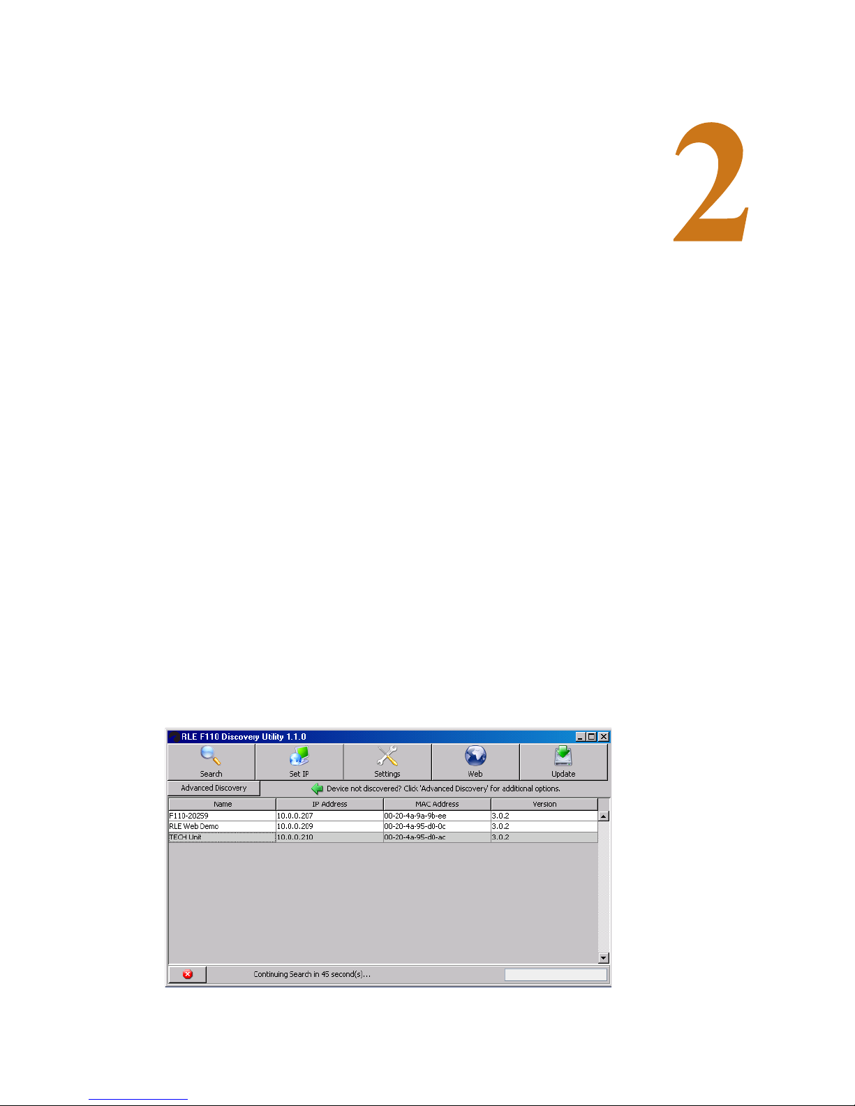
The F110 default is configured with a DHCP IP Address. The RLE Device Discovery Utility
scans the network and locates all F110 devices connected to the network. This provides an
efficient way to manage large numbers of F110 devices from a single host system.
Note The default DHCP name on the F110 is 'F110 -<5 digit number>'. This 5 digit number will be the
serial number located on the bottom of the F110.
The Device Discovery Utility is available on your RLE Product User Guide CD, included with
your F110. It is also available for download on the Documentation/Files section of the F110
webpage at www.rletech.com. Install and run the Device Discovery Utility.
Figure 2.1
www.rletech.com 15 970.484.6510
Device Discovery Utility

2 Getting Started
Note If the Device Discovery Utility can not find the F110, reset the unit by unplugging the power
2.2.1 Search
Select the Search button to scan the network for the F110 hardware devices. If an F110 is
physically attached to your network anywhere it will be located in this scan.
adapter and then plugging it back in. Also, make sure that UDP port “30718” is not restricted on
your network by a router, switch, network firewall or software firewall.
2.2.2 Set IP
Select the Set IP button to enter a static IP address, gateway IP address and subnet mask for the
selected F110. To configure a dynamic IP address, set the IP to 0.0.0.0. When configured for a
dynamic IP address, F110 will attempt to obtain an IP address automatically via DHCP.
Figure 2.2
IP Pop-up Box
2.2.3 IP Address Assignment for Static Only Networks
If the network is not configured for DHCP, a static IP address will need to be set before the
F110 can be accessed. After discovering the unit, it will be displayed with an IP address. Click
the Set IP button to assign a static IP address only. After the F110 reboots (i.e,. it takes about 4
seconds) with the new IP address, select the Search button on the Device Discovery Utility.
Next, select the F110 that was just assigned a static IP and then select the Set IP button. Finally,
fill in the gateway IP address and subnet mask for the selected ID Box.
2.2.4 Settings
Click the Settings button to open the Settings Applet on the web browser interface for the
selected device. The Settings Applet can then be used to configure that specific F110.
2.2.5 Web
Click the Web button to open the web browser interface for the selected F110. This is useful for
viewing the current sensor status.
www.rletech.com 16 970.484.6510

2.2.6 Update
WARNING
Click the Update button to update the firmware installed on the selected F110. Updated
firmware files provided by RLE, add new features and enhance the web browser interface.
These firmware updates are available from RLE if firmware replacement is necessary.
Note When obtaining the F110 Firmware Update file from the RLE Technologies website, be sure to
save the file instead of opening it from a web browser. After receiving the file, right-click the
F110 Firmware Update file and select “Properties.” If the F110 Firmware Update file has a “.zip”
extension, replace “.zip” with “.upd” before uploading the file with the Device Discovery Utility.
2.3. F110 Wiring
RLE recommends an 18AWG stranded copper wire for connection from each monitored point
to the terminal block (TB) connection on the F110 (8 Switched Sensors inputs only). RLE
recommends no more than 200 feet (60.9m) of wire at this specification. If longer runs are
needed, please contact RLE for application guidance.
2.3.1 Power Supply
2 Getting Started
Plug the wall adapter into the connection labeled Power. The wall adapter has a 6 foot
(18.82m) power cord. RLE recommends powering the F110 from a UPS supply to allow the
F110 to send alarm notification during a power outage.
Figure 2.3
NEVER connect main power to the sensors or sensor cables.
5VDC Power Supply Connection
www.rletech.com 17 970.484.6510
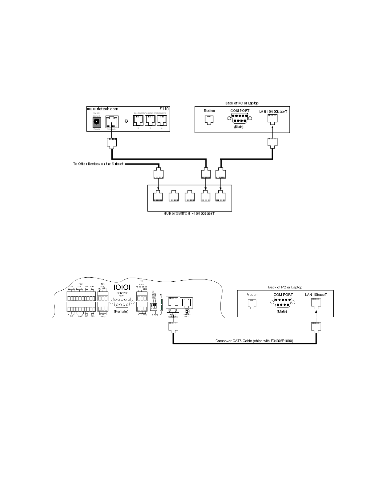
2 Getting Started
2.3.2 RJ45 Ethernet Connection
The F110 has an internal 10/100BaseT Ethernet port used to configure and monitor the F110.
The Ethernet port supports Web browser access, email (SMTP), Modbus, and SNMP. The
following figures show the physical connection.
Figure 2.4
Physical Connection
Figure 2.5 shows a typical F110 connection on a subnet using a hub or switch and straight
through Network Patch cables.
Figure 2.5
F110 Ethernet Connection to a PC on a Subnet
www.rletech.com 18 970.484.6510

CHAPTER 0F110 WEB INTERFACE
3.1. F110 Web Interface Overview
The F110’s Web interface provides a convenient way to check the F110’s status and
reconfigure basic settings from any internet enabled computer. Enter the IP address of the F110
into your web browser’s address bar. The F110 Main Page will appear.
C HAPTER
3.2. Status Screen
Figure 3.1
F110 Status Screen
The Falcon F110 Status Screen is available through the built-in web server and shows the
current status of the attached sensors. If high and low alert thresholds are defined for the
temperature or temperature/humidity sensors, the status icon above the sensor label changes
www.rletech.com 19 970.484.6510

3 F110 Web Interface
color based upon where the temperature or humidity is in relation to the established high and
low thresholds.
If the temperature or humidity is between the high and low thresholds and more than five (5)
degrees from either threshold, the status icon will be green. If it is within five (5) degrees of the
high threshold, the status icon will be yellow. If it is within five (5) degrees of the low threshold,
the status icon will be blue. If the high or low threshold is exceeded, the status icon will be red.
If no thresholds are currently defined, the status icon will be gray.
The Status screen also displays the current status of any switch sensors connected to the F110.
If the status icon above the switch sensor is red, then that switch sensor is currently in an alarm
state. Below the status icon and switch sensor label, the current switch sensor state will be
displayed. If you are unsure as to which state (i.e. open or closed) to set for the switch sensor
alarm state and the switch sensor is not currently in an alarm state, set the alarm state to be the
opposite of what is displayed here. Refer to the manual of each sensor for information on the
normal state (open or closed) of the switch sensor in use.
Below the DHCP Name and time display are a number of radio buttons and form fields that
allow the display of the F110 web server interface to be modified. Changing the Display radio
buttons will toggle how inactive sensors are displayed, modifying the Update Every form field
will adjust the refresh time of the F110 web server interface and selecting the Celsius radio
button instead of the Fahrenheit radio button will display sensor values in Celsius.
3.3. Settings Screen
The F110 Settings Screen is used to modify the F110 configuration. Here users can configure
Network, Email, SNMP, Alert Threshold, Security, and Advanced settings. When settings are
modified and saved, the F110 will automatically reset and start with the new configuration.
Note After you make a field change, click on Accept Changes at the bottom of the screen, then click
on Save Settings on the left hand column.
You will see an authentication security prompt appear once accessing the Settings Menu.
Default from RLE, there is no USER name and NO password assigned to the unit. A password
can be assign to the unit later during the configuration. There is no USER name assigned to the
unit, at this time.
Figure 3.2
www.rletech.com 20 970.484.6510
Authentication Security Prompt (no Username or Password)

3 F110 Web Interface
Note There is no user name or no password from RLE. Password can be assigned to the unit later in
the configuration menu. There is no user name that can be configured at this time.
3.3.1 Network
The Network tab stores settings to control how the F110 appears on the local network.
Modifying the DHCP name will change how the F110 reports to the DHCP server when
attempting to obtain a dynamic IP address. This label must be unique, so when assigning the
DHCP Name ensure that duplicate labels do not appear on the network.
To set a static IP address, uncheck the Use DHCP checkbox and enter the Static IP, Gateway
IP, and Subnet Mask.
If you wish to use a DNS name instead of an IP address for the Mail Server Address on the
Email tab, enter the IP address of your DNS Server in the DNS Server IP field.
Note In most cases, the DNS Server IP address is the same as the IP address entered into the
“Gateway IP” field. If this does not work, please contact your network administrator for
assistance.
Figure 3.3
Note If using SNMP monitoring software to monitor the F110, it is recommended that a static IP
address be assigned to the device to ensure that the software can find the unit. The IP address
assigned must also be excluded from DHCP assignment to ensure that the IP address of the
F110 is NOT given to another device on your network. Please contact your Network
Administrator for assistance.
www.rletech.com 21 970.484.6510
Network Settings

3 F110 Web Interface
3.3.2 Email
The Email tab stores settings for the F110 to send Email Alert Notifications when alert
thresholds are exceeded. In order to enable email alerting from the F110's web server interface,
your mail server must have SMTP Relay enabled for either your network or the IP address of
the F110. Contact your Email Administrator if you need assistance.
Enter the mail server address for the mail server you are using in the Mail Server Address
field. The address can be entered as either the IP address or the DNS name of your mail server.
If you wish to use a DNS name for the Mail Server Address field, you must assign a Static IP
address, Gateway IP address, DNS Server IP address, and Subnet Mask on the Network tab.
In the Email Recipients fields, you can enter a single/regular email address, distribution list
email address or mobile phone, pager or PDA email address (using Email-To-SMS) for email
alert when alert thresholds are exceeded. Only one address may be entered.
The Return Address (From) field MUST contain an email address for an active account on the
mail server specified in the Mail Server Address field. For example, if 'mail.rletech.com' is
entered in the Mail Server Address field, the Return Address (From) field must contain an
email address with the 'mail.rletech.com' domain. Contact your email administrator if you
require additional assistance.
The F110 can also do authenticated SMTP (ESMTP). Enter your user name and password in
the fields and select the check box for Enable Authentication. You MUST save your settings
before sending a test email. Refer to xrefpg. X for Trace output, to view mail transfer
information between the F110 and mail server for troubleshooting.
Note You must save your settings before sending a test email.
Figure 3.4
www.rletech.com 22 970.484.6510
Email Settings

3 F110 Web Interface
Note Many email servers block SMTP email by default. To use SMTP email with the F110, be sure
the F110 IP address is added to the list of allowed SMTP relay hosts on the email server you
are using for email.
Note After you make a field change, click on Accept Changes at the bottom of the screen, after
verifying the settings are ok, click on the Save Settings tab located on the left hand column.
3.3.3 SNMP
The SNMP tab stores settings allowing the F110 to respond to SNMP Query requests from
network monitoring applications. Enter the 'Community Name' to use for accessing the SNMP
data via SNMP Query for the F110 sensors. If the SNMP feature of the F110 is used, F110 MIB
files are available for download on the Documentation/Files section of the F110 webpage at
www.rletech.com, or by contacting RLE via support@rletech.com.
The F110 can also send SNMP Traps in response to alerts. Enter up to three (3) IP addresses on
the SNMP tab and F110 will send SNMP Traps to these systems for processing by network
monitoring applications.
Figure 3.5
Note After you make a field change, click on Accept Changes at the bottom of the screen, after
verifying the settings are ok, click on the Save Settings tab located on the left hand column.
www.rletech.com 23 970.484.6510
SNMP Settings

3 F110 Web Interface
3.3.4 Channel 2, Channel 3 and Channel 4
The Channel 2, Channel 3 and Channel 4 tabs are used to configure sensor labels and to set
temperature thresholds, temperature/humidity thresholds and/or alarm states for the sensors
connected to sensor channels 2, 3 and 4 on the front of the F110. Sensor labels can be up to 14
characters in length.
Depending on whether an external temperature / humidity sensor, external temperature sensor
or any additional external sensor is plugged into the sensor channel, configuration of each
specific channel may vary.
3.3.4.1 External Temperature/Humidity
High and low thresholds can be defined for each temperature/humidity sensor. If the current
temperature and/or humidity rises above the high threshold or falls below the low threshold, an
alert will be generated. When the temperature and/or humidity returns to a normal state, the alert
will clear and a follow-up notification will be sent.
The temperature/humidity sensors can be calibrated, if necessary, by entering correction values
in the Adjust field for each temperature/humidity sensor. Temperature corrections entered here
can only be entered in degrees Celsius (i.e. °Celsius = [5/9]*[°Fahrenheit-32]). Humidity
corrections are entered in percent (%) Relative Humidity. To adjust the temperature and/or
humidity down, enter a minus (-) sign before the value (i.e. -5). All temperature alert thresholds
must be entered in degrees Fahrenheit and all humidity alert thresholds must be entered in
percent (%) Relative Humidity.
Field Temperature Units
High Fahrenheit
Low Fahrenheit
Adjust Celsius
www.rletech.com 24 970.484.6510

3 F110 Web Interface
Figure 3.6
Sensor Settings
3.3.5 Switched Sensor Alarm Configuration
The Channel 1 tab is used to configure sensor labels and alarm states (normally open or closed)
for the eight (8) switch sensor ports (dry contact inputs) on the back of the F110 unit. Sensor
labels can be up to 15 characters in length.
Alert Thresholds for switch sensors connected to the eight (8) sensor ports on the back of the
F110 are set by specifying either CLOSED or OPEN. Please refer to the documentation
received with any sensor purchased to determine the 'normal' state (open or closed) for that
specific sensor type. Next, select the opposite state (i.e. not normal) to configure the F110 for
its alarm state, which will cause it to send an alert when the alarm condition exists.
3.3.6 Security
The Security tab is used to configure password security for access to the F110 Settings Screen.
Passwords can ONLY contain the alphanumeric characters “0-9”,”'a-z” and “A-Z”. Spaces,
symbols, and punctuation are not supported. Be sure to record the password entered here in a
secure location.
www.rletech.com 25 970.484.6510
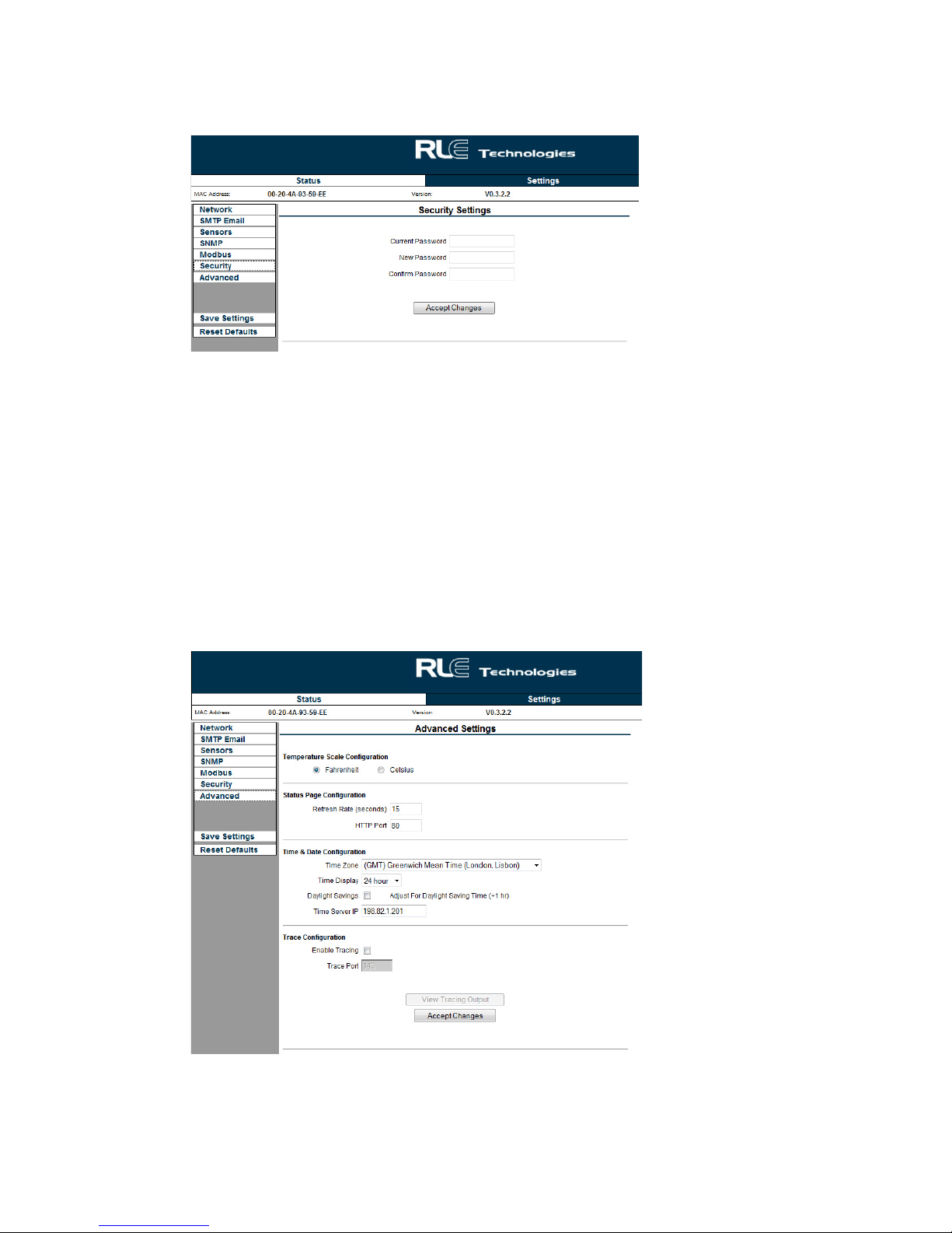
3 F110 Web Interface
Figure 3.7
Security Settings
3.3.7 Advanced
The Advanced tab is used to configure the Temperature Scale Configuration, Time & Date
Configuration by connecting to a NTP server and provides a Trace Configuration for
diagnostics when communicating to other equipment. If you wish to modify the time display on
the Status screen to the local time zone, use the drop down box to select your local time zone,
check the Daylight Savings Time checkbox if applicable and click Save Settings. The Time
Server IP field can be used to manually enter a specific time server to use for the time display if
access to the Internet is restricted or not available and a time server is available for use on the
local network.
Figure 3.8
www.rletech.com 26 970.484.6510
Advanced Settings
3 F110 Web Interface
Temperature Scale Conversion: You can select how the F110 displays the Temperature
output on the Status page, either being Fahrenheit or Celsius.
Time & Date Configuration: Enter an IP address of a NTP server for the F110 to synchronize
with for displaying current date and time information.
Trace Configuration: This feature enable you to open a secondary window to view
communication between the F110 and other devices, such as a Mail Server, Modus Master and
SNMP manager. This feature aids in troubleshooting if communication is not being made. To
use Tracing Output, click on the enable tracing box, save your settings. Go back to the
Advanced screen after the changes have been made and left click the View Tracing Output
button.
Note If Daylight Savings Time is used in your location, be sure to toggle the “Daylight Savings Time'”
checkbox when Daylight Savings Time is not being observed.
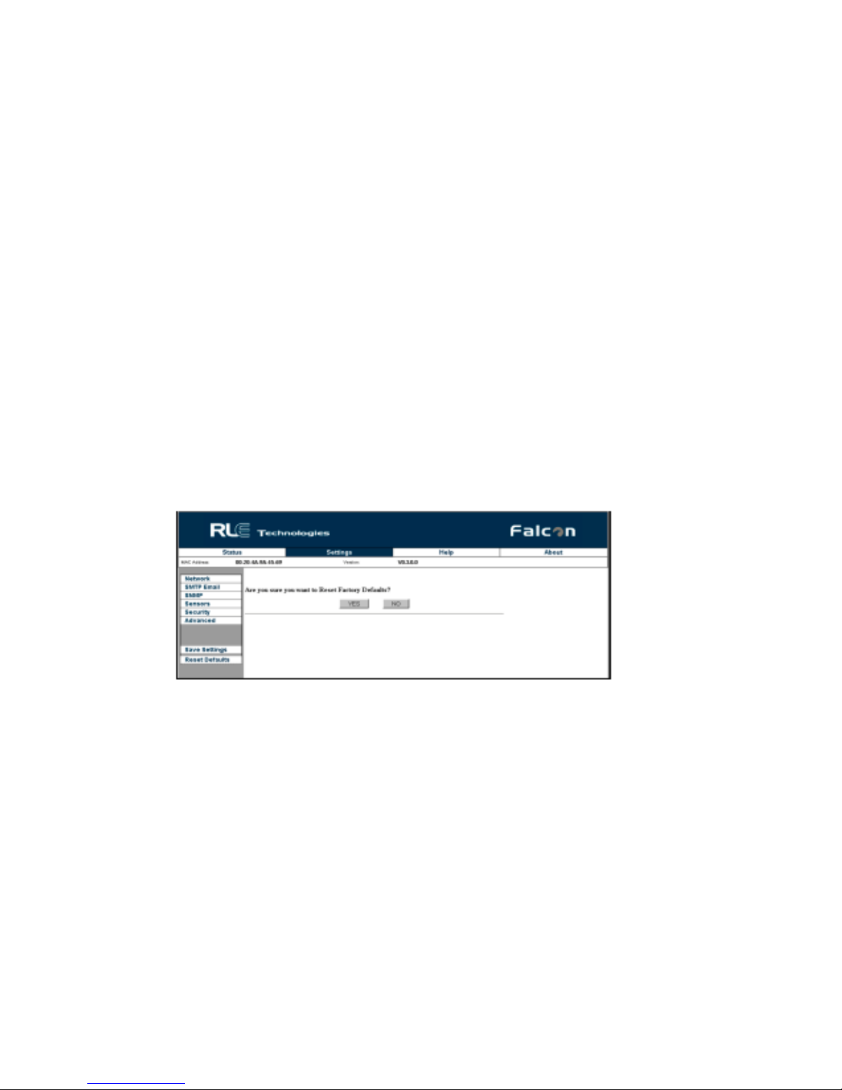
3.3.8 Reset Defaults
The Reset Factory Defaults button will reset the F110 to its default factory configuration,
clearing any configuration changes made to the F110. Use this as a LAST resort if you are
experiencing difficulties configuring the F110. You will have to rediscover the F110 once
submitting. Write down the F110 MAC address before resetting to factory defaults.
Figure 3.9
www.rletech.com 27 970.484.6510
Restore Defaults Prompt

3 F110 Web Interface
3.3.9 Help Screen
The Help screen displays the current firmware on the F110 unit. There are hyperlinks available
for contacting RLE Technologies, RLE Technical Support, and Web Site link for viewing other
RLE products and information.
Figure 3.10
Help Screen
3.3.10 About Screen
The About screen also displays current information and provides links and information for
contacting RLE Technologies.
Figure 3.11
About Screen
www.rletech.com 28 970.484.6510
CHAPTER 0MODBUS CONFIGURATION VIA TELNET
A.1. F110 Modbus Capabilities
By default, the F110 is enabled to listen on TCP port 502 for Modbus requests. The Modbus
module can be enabled or disabled, the TCP port can be changed, and a list of IP addresses can
be specified and used to either allow or deny Modbus requests.
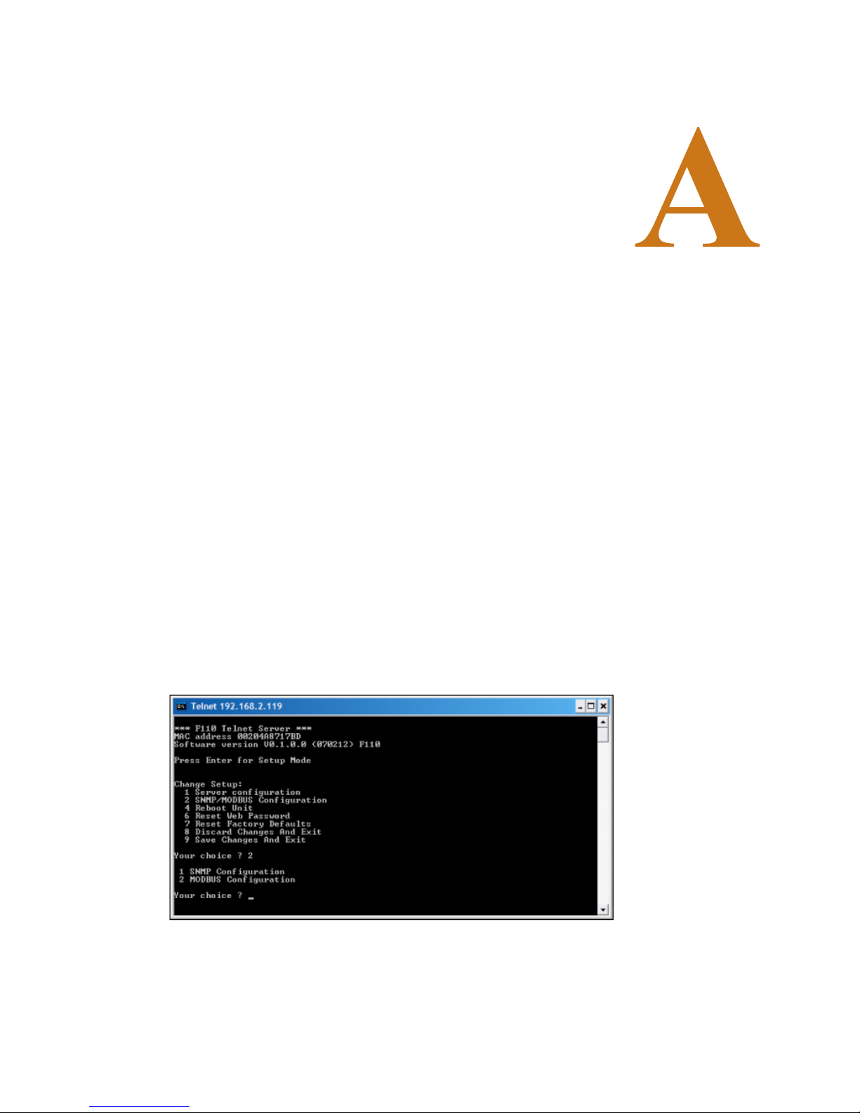
A.2. Telnet Configuration
A PPENDIX
Modbus can be configured through the F110 Telnet interface. To open the Telnet interface, type
the following on the command line being sure to replace <IP Address> with the IP address of
the F110:
telnet <IP Address> 9999
Press Enter when prompted to enter Setup Mode. If Enter is not pressed within three (3)
seconds, the connection will be closed automatically.
Figure A.1
Enter 2 and press Enter to select the SNMP/MODBUS Configuration option. At the next
prompt, enter 2 and press Enter to select the MODBUS Configuration option. Follow the
prompts below to configure Modbus on the F110.
www.rletech.com 29 970.484.6510
Telnet Connection

A Modbus Configuration Via Telnet
Enable MODBUS? (N)?
Enter Y to enable Modbus and N to disable it. When Modbus is disabled, the F110 will not
actively listen on the Modbus TCP port for Modbus requests.
MODBUS Port: (502)
By default, the F110 listens for Modbus requests on TCP port 502. This port can be changed to
any valid TCP port number although it is recommended to leave it set for port 502 to ensure
compatibility with other Modbus devices on the network.
Should IP List Allow or Deny Connections (0=Allow, 1=Deny):
The F110 is configured by default to deny connections from any IP addresses listed in the
Modbus IP list. When all IP addresses in this list are set to default (0.0.0.0) the F110 will deny
connections from no devices. In other words, by default the F110 allows connections from all IP
addresses. This can be modified if desired so that the F110 will only allow connections from IP
addresses appearing in the IP list. Selecting “0=Allow” will only allow connections from the IP
addresses provided in the list and deny connections from all other addresses. Selecting
“1=Deny” will deny connections from all address in the list but accept from all other addresses.
Enter IP addresses for MODBUS Security:
Up to three (3) IP addresses can be specified and added to the Modbus IP list. This list can be
used to either allow or deny connections if the IP address that the request originated from
matches an IP address in the list. To configure IP addresses, enter each IP address when
prompted or enter 0.0.0.0 to leave blank.
Save Changes And Exit
When configuration changes are complete, press 9 and Enter to save the changes and exit. The
F110 will reboot and apply the new settings.
www.rletech.com 30 970.484.6510

A PPENDIX
CHAPTER 0MODBUS REGISTERS
Table B.1
Read Output Registers
Register Name Description Units Range
40002 FC Family Code (8 Switch Sensors) None 0-65535
40003 SS Switch Status (8 Switch Sensors) None 0-65535
40004 SC Current Alarm Setting (8 Switch Sensors) None 0-65535
40005 AS Current Alarm State (8 Switch Sensors) None 0-65535
40009 FC Family Code (External Sensor 1) None 0-65535
40010 TC Current Temperature (External Sensor 1) Celsius x100 0-65535
40011 TH High Temperature (External Sensor 1) Celsius x100 0-65535
40012 TL Low Temperature (External Sensor 1) Celsius x100 0-65535
40013 HC Current Humidity (External Sensor 1) % Relative Humidity 0-65535
40014 HH High Humidity (External Sensor 1) % Relative Humidity 0-65535
40015 HL Low Humidity (External Sensor 1) % Relative Humidity 0-65535
40016 FC Family Code (External Sensor 2) None 0-65535
40017 TC Current Temperature (External Sensor 2) Celsius x100 0-65535
40018 TH High Temperature (External Sensor 2) Celsius x100 0-65535
40019 TL Low Temperature (External Sensor 2) Celsius x100 0-65535
40020 HC Current Humidity (External Sensor 2) % Relative Humidity 0-65535
40021 HH High Humidity (External Sensor 2) % Relative Humidity 0-65535
40022 HL Low Humidity (External Sensor 2) % Relative Humidity 0-65535
40023 FC Family Code (External Sensor 3) None 0-65535
40024 TC Current Temperature (External Sensor 3) Celsius x100 0-65535
40025 TH High Temperature (External Sensor 3) Celsius x100 0-65535
www.rletech.com 31 970.484.6510

B Modbus Registers
Table B.1
Read Output Registers (continued)
Register Name Description Units Range
40026 TL Low Temperature (External Sensor 3) Celsius x100 0-65535
40027 HC Current Humidity (External Sensor 3) % Relative Humidity 0-65535
40028 HH High Humidity (External Sensor 3) % Relative Humidity 0-65535
40029 HL Low Humidity (External Sensor 3) % Relative Humidity 0-65535
40038 TC Current Temperature (External Sensor 1) Fahrenheit x100 0-65535
40039 TH High Temperature (External Sensor 1) Fahrenheit x100 0-65535
40040 TL Low Temperature (External Sensor 1) Fahrenheit x100 0-65535
40045 TC Current Temperature (External Sensor 2) Fahrenheit x100 0-65535
40046 TH High Temperature (External Sensor 2) Fahrenheit x100 0-65535
40047 TL Low Temperature (External Sensor 2) Fahrenheit x100 0-65535
40052 TC Current Temperature (External Sensor 3) Fahrenheit x100 0-65535
40053 TH High Temperature (External Sensor 3) Fahrenheit x100 0-65535
40054 TL Low Temperature (External Sensor 3) Fahrenheit x100 0-65535
Table B.2
Family Code (Register 40002, 40009, 40016, 40023: FC)
Hexadecimal
Value
Decimal Value Description
0x29 41 8 Switch Sensor
0x10 16 Temperature Sensor
0x26 38 Temperature and Humidity Sensor
0x00 00 No Sensor
Table B.3
Status Flags (Register 40003: SS)
Bit Status Flag
00 Switch Sensor 1 Status; 1 = On, 0 = Off
01 Switch Sensor 2 Status; 1 = On, 0 = Off
02 Switch Sensor 3 Status; 1 = On, 0 = Off
03 Switch Sensor 4 Status; 1 = On, 0 = Off
04 Switch Sensor 5 Status; 1 = On, 0 = Off
05 Switch Sensor 6 Status; 1 = On, 0 = Off
06 Switch Sensor 7 Status; 1 = On, 0 = Off
www.rletech.com 32 970.484.6510

B Modbus Registers
Table B.3
Status Flags (Register 40003: SS) (continued)
Bit Status Flag
07 Switch Sensor 8 Status; 1 = On, 0 = Off
08-15 Spare
Table B.4
Status Flags (Register 40004: SC)
Bit Status Flag
00 Switch Sensor 1 Alarm On: 1 = Closed, 0 = Open
01 Switch Sensor 2 Alarm On: 1 = Closed, 0 = Open
02 Switch Sensor 3 Alarm On: 1 = Closed, 0 = Open
03 Switch Sensor 4 Alarm On: 1 = Closed, 0 = Open
04 Switch Sensor 5 Alarm On: 1 = Closed, 0 = Open
05 Switch Sensor 6 Alarm On: 1 = Closed, 0 = Open
06 Switch Sensor 7 Alarm On: 1 = Closed, 0 = Open
07 Switch Sensor 8 Alarm On: 1 = Closed, 0 = Open
08-15 Spare
Table B.5
Status Flags (Register 40005: AS)
Bit Status Flag
00 Switch Sensor 1 Alarm State; 1 = Alarm, 0 = Normal
01 Switch Sensor 2 Alarm State; 1 = Alarm, 0 = Normal
02 Switch Sensor 3 Alarm State; 1 = Alarm, 0 = Normal
03 Switch Sensor 4 Alarm State; 1 = Alarm, 0 = Normal
04 Switch Sensor 5 Alarm State; 1 = Alarm, 0 = Normal
05 Switch Sensor 6 Alarm State; 1 = Alarm, 0 = Normal
06 Switch Sensor 7 Alarm State; 1 = Alarm, 0 = Normal
07 Switch Sensor 8 Alarm State; 1 = Alarm, 0 = Normal
08-15 Spare
www.rletech.com 33 970.484.6510

B Modbus Registers
Notes:
www.rletech.com 34 970.484.6510

A PPENDIX
CHAPTER 0TECHNICAL SPECIFICATIONS
Table C.1
Technical Specifications
Power 5VDC @ 800mA max.; wall adaptor included
Wall Adapter Input 110/240VAC 50/60Hz
Inputs
Temperature/Humidity 3 Digital temperature or digital temperature/humidity sensor
inputs; plug-and-play; configurable alarm points
Digital (Dry Contact) 8 Digital alarm points (configurable) / Dry contacts (gold/Au clad)
Input Cable Length 25ft (7.62m) standard; maximum length up to 100ft (30.48m)
Communications Ports
Ethernet 10/100 BaseT, RJ45 connector; DHCP enabled (default); Static
IP-addressable
Protocols
TCP/IP; NTP IPv4.0
HTTP/HTML; Telnet 1.1/4.0
SNMP V1; NMS manageable with Get, and Traps; V2c- Traps or
Informs
SMTP (Email) Slave; RTU Mode; Supports function codes 03, 04, 06 and 16
Modbus (TCP/IP) Modbus slave; TCP/IP transmission protocol
Alarm Notification
Email 1 Email field (for one or multiple recipients); email sent on alarm;
SNMP Traps 1 Community string with up to 3 manager IP addresses
Login Security
Web Browser Access 1 Universal web password for administrator access
Front Panel Interface
LED Indicators Power: 1 green; Network Link: 1 green;
www.rletech.com 35 970.484.6510
alarms notify email recipients; regular email, distribution list, or
email-to-SMS accepted
Network Activity: 1 amber

C Technical Specifications
Table C.1
Technical Specifications (continued)
Operating Environment
Temperature -40°F to 185°F (-40°C to 85°C)
Humidity 5% to 85% RH, non-condensing
Altitude 15,000ft (4,572m) max.
Storage Environment -40°F to 185°F (-40°C to 85°C)
Dimensions
Box Enclosure 4.56"W x 1.25"H x 2.25"D
(115.8mmW x 31.75mmH x 57.15mmD)
Rack Mount – Optional 19.0"W x 1.75"H x 3.75"D
(482.6mmW x 44.45mmH x 95.25mmD)
Weight
Box Enclosure 10 oz. (283g))
Rack Mount – Optional 20 oz. (567g))
Mounting Rack mount (brackets required): F110-RMB rack mount brackets
(not included)
Temperature Sensor – Optional F110-TS (optional); includes 25ft (7.62m) leader cable with
RJ-11 connector (100ft/30.48m distance max.)
Range: -67°F to 127°F (-55°C to 52°C)
Temperature/Humidity Sensor – Optional F110-THS (optional); includes 25ft (7.62m) leader cable with
RJ-11 connector (100ft/30.48m distance max.)
Range: -67°F to 127°F (-55°C to 52°C)
Certifications CE; UL STD 17DU E248122; EN STD 5502; ICES-003 Issue 4;
FCC 47 CFR Part 15; VCCI; AS/NZS CISPR 22; EN 61326
www.rletech.com 36 970.484.6510
 Loading...