

Page 1

Integration
Protocol
Converter
User Guide
Version 2.4
Firmware Version 5.3.19
Page 2
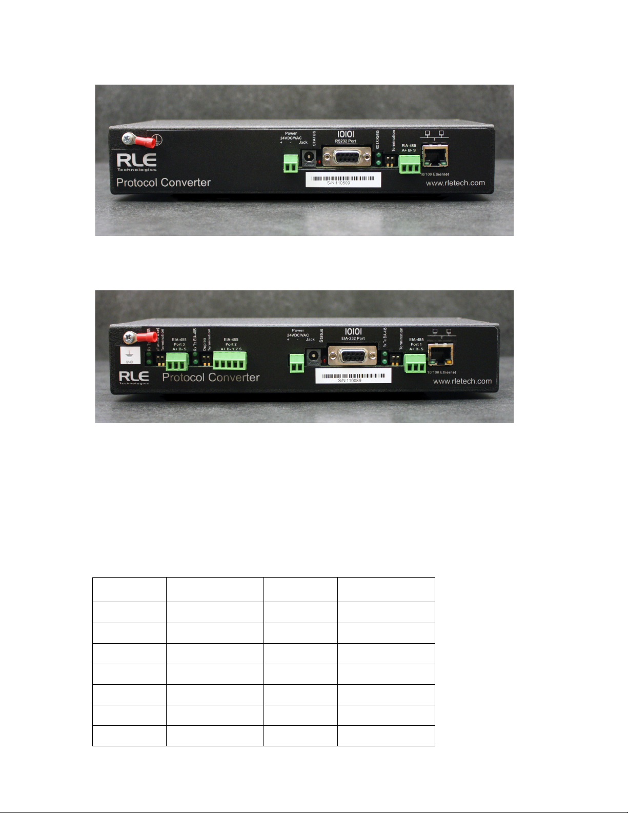
Figure 1.1
Protocol Converter (FDS-PC)
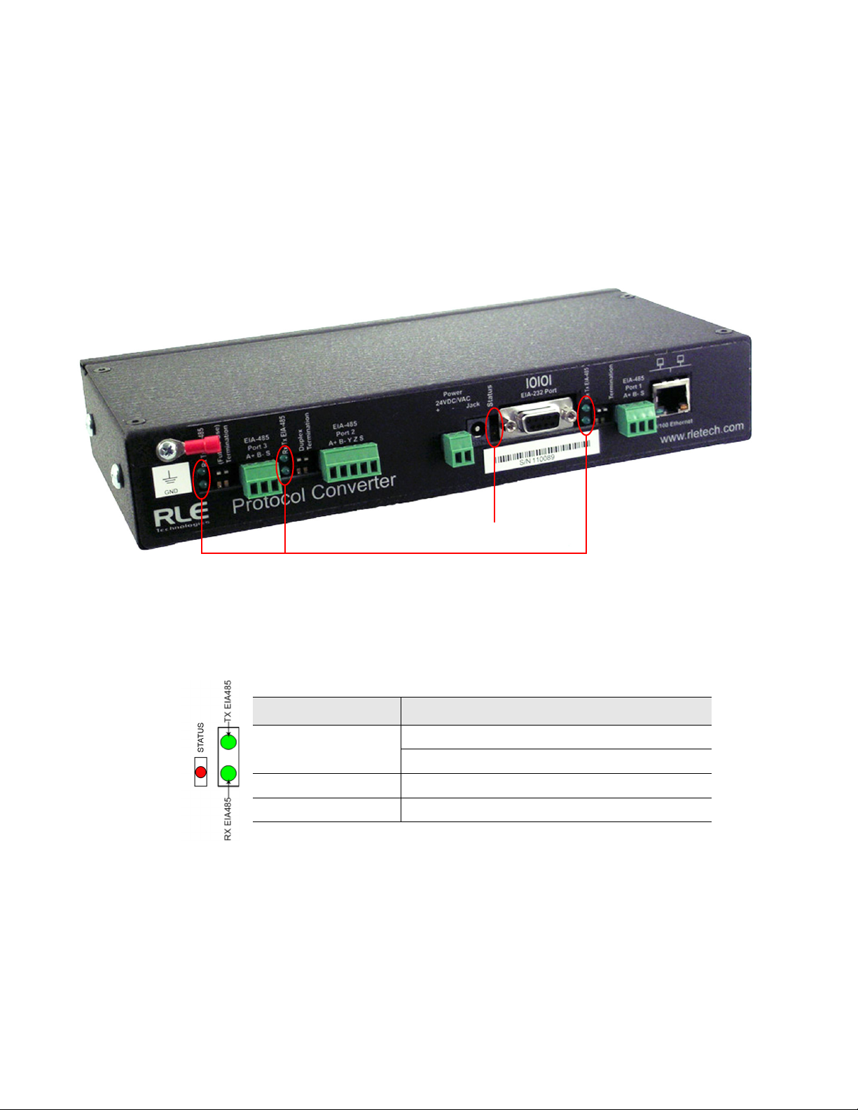
Figure 1.2
Dual Port Protocol Converter (FDS-PC-DP)
Copyright and Trademark Notices
© Raymond & Lae Engineering, Inc. 2011. All rights reserved. RLE® is a registered trademark and
Seahawk™, Falcon™, and Raptor™ are trademarks of Raymond & Lae Engineering, Inc. The
products sold by Raymond & Lae Engineering, Inc. are subject to the limited warranty, limited liability,
and other terms and conditions of sale set forth at http://rletech.com.
Revision History
Rev. No. Date Rev. No. Date
1.0 June 2010 2.4 October 2014
1.1 August 2010
1.2 May 2011
2.0 November 2013
2.1 February 2014
2.2 February 2014
2.3 June 2014
2 Protocol Converter User Guide 800.518.1519
Page 3

Product Registration
Product registration helps RLE Technologies inform owners of:
• Product upgrades
• New products and technologies
• Special offers available only to registered users
Submit registration information on our website: www.rletech.com.
Any information provided to RLE Technologies through the registration form will be regarded as
confidential. RLE will not sell or distribute any of the information to third parties. To read our privacy
policy, please visit our website: www.rletech.com.
Technical Support
Personal assistance is available Monday through Friday, from 8:00 a.m. to 5:00 p.m. Mountain Time.
A request for assistance may be sent to support@rletech.com.
Otherwise, please call us directly at: 800.518.1519, and press “2” for technical support.
The following information is located on the bottom of each Protocol Converter unit. Please have this
information available whenever a technical support call is placed:
Product Model Number
Product Serial Number
Product Manufacture Date
rletech.com Protocol Converter User Guide 3
Page 4

RLE Product Warranty
Seller warrants to the Ultimate Purchaser (the purchaser who buys for use and not for resale) that all
products furnished under this order and which are manufactured by Seller will conform to final
specifications, drawings, samples and other written descriptions approved in writing by Seller, and will be
free from defects in materials and workmanship. These warranties shall remain in effect for a period of
twelve (12) months after shipment. If the Seller installs the equipment or supplies technical direction of
installation by contract, said one year shall run from the completion of installation, provided installation is not
unreasonably delayed by Ultimate Purchaser. Parts replaced or repaired in the warranty period shall carry
the unexpired portion of the original warranty. A unit placed with the purchaser on consignment and then
later purchased will be warranted for twelve (12) months from the time the Seller receives notification of the
Purchaser's intent to purchase said consigned item. The foregoing is in its entirety is subject to the provision
that in no case will the total warranty period extend beyond 18 months from date Seller ships equipment
from point of manufacture.
Products are NOT life and safety certified. In no event shall the Seller be liable for loss, damage, or expense
directly or indirectly arising from the use of the units, or from any other cause, except as expressly stated in
this warranty. Seller makes no warranties, express or implied, including any warranty as to merchantability
or fitness for a particular purpose or use. Seller is not liable for and Purchaser waives any right of action it
has or may have against Seller for any consequential or special damages arising out of any breach of
warranty, and for any damages Purchaser may claim for damage to any property or injury or death to any
person arising out of its purchase or the use, operation, or maintenance of the product. Seller will not be
liable for any labor subcontracted or performed by Purchaser for preparation of warranted item for return to
Seller's factory or for preparation work for field repair or replacement. Invoicing of Seller for labor either
performed or subcontracted by Purchaser will not be considered as a liability by the Seller.
The liability of Seller hereunder is limited to replacing or repairing at Seller's factory or on the job site at
Seller's option, any part or parts which have been returned to the Seller and which are defective or do not
conform to such specifications, drawings or other written descriptions; provided that such part or parts are
returned by the Ultimate Purchaser within ninety (90) days after such defect is discovered. The Seller shall
have the sole right to determine if the parts are to be repaired at the job site or whether they are to be
returned to the factory for repair or replacement. All items returned to Seller for repair or replacement must
be sent freight, prepaid to its factory. Purchaser must obtain Seller's Return Goods Authorization prior to
returning items. The above conditions must be met if warranty is to be valid. Seller will not be liable for any
damage done by unauthorized repair work, unauthorized replacement parts, from any misapplication of the
item, or for damage due to accident, abuse, or act of God.
This warranty shall be exclusive of any and all other warranties express or implied and may be modified only
by writing signed by any officer of the Seller. This warranty shall extend to the Ultimate Purchaser but to no
one else. Accessories supplied by Seller but manufactured by others carry any warranty the manufacturers
have made to Seller and which can be passed on to the Ultimate Purchaser.
Seller makes no warranty with respect to whether the products sold hereunder infringe any patent, U.S. or
foreign, and Purchaser represents that any specially ordered products do not infringe any patent. Purchaser
agrees to indemnify and hold Seller harmless from any liability by virtue of any patent claims where
Purchaser has ordered a product conforming to Purchaser's specifications, or conforming to Purchaser's
specific design.
Purchaser has not relied and shall not rely on any oral representation regarding the Product sold hereunder
and any oral representation shall not bind Seller and shall not be part of any warranty.
4 Protocol Converter User Guide 800.518.1519
Page 5

Contents
1 Product Overview . . . . . . . . . . . . . . . . . . . . . . . . . . . . . . . . . . . . . . . . . . . . . . . . . . . 11
Introduction . . . . . . . . . . . . . . . . . . . . . . . . . . . . . . . . . . . . . . . . . . . . . . . . . . . . . . . . . . . . . . . . . . . . . . 11
Product Description. . . . . . . . . . . . . . . . . . . . . . . . . . . . . . . . . . . . . . . . . . . . . . . . . . . . . . . . . . . . . . . . 11
Rear Panel Indicators. . . . . . . . . . . . . . . . . . . . . . . . . . . . . . . . . . . . . . . . . . . . . . . . . . . . . . . . . . 12
Terminal Block Designations . . . . . . . . . . . . . . . . . . . . . . . . . . . . . . . . . . . . . . . . . . . . . . . . . . . . 13
SW1 Switch Settings . . . . . . . . . . . . . . . . . . . . . . . . . . . . . . . . . . . . . . . . . . . . . . . . . . . . . . . . . . 14
2 Installation . . . . . . . . . . . . . . . . . . . . . . . . . . . . . . . . . . . . . . . . . . . . . . . . . . . . . . . .15
Register the Protocol Converter . . . . . . . . . . . . . . . . . . . . . . . . . . . . . . . . . . . . . . . . . . . . . . . . . . . . . . 15
Mount the Protocol Converter . . . . . . . . . . . . . . . . . . . . . . . . . . . . . . . . . . . . . . . . . . . . . . . . . . . . . . . . 15
Wire the Protocol Converter . . . . . . . . . . . . . . . . . . . . . . . . . . . . . . . . . . . . . . . . . . . . . . . . . . . . . . . . . 16
Power Supply & Ground Connections . . . . . . . . . . . . . . . . . . . . . . . . . . . . . . . . . . . . . . . . . . . . . 16
RJ45 Ethernet Connection . . . . . . . . . . . . . . . . . . . . . . . . . . . . . . . . . . . . . . . . . . . . . . . . . . . . . . 17
EIA-232 COM Connection . . . . . . . . . . . . . . . . . . . . . . . . . . . . . . . . . . . . . . . . . . . . . . . . . . . . . . 18
Modbus EIA-485 Connections . . . . . . . . . . . . . . . . . . . . . . . . . . . . . . . . . . . . . . . . . . . . . . . . . . . 19
3 Configuration . . . . . . . . . . . . . . . . . . . . . . . . . . . . . . . . . . . . . . . . . . . . . . . . . . . . . . 21
Configure Communications. . . . . . . . . . . . . . . . . . . . . . . . . . . . . . . . . . . . . . . . . . . . . . . . . . . . . . . . . . 21
Set the IP Address Using a Web Browser . . . . . . . . . . . . . . . . . . . . . . . . . . . . . . . . . . . . . . . . . . 22
Set the IP Address Using an EIA-232 Connection. . . . . . . . . . . . . . . . . . . . . . . . . . . . . . . . . . . . 24
Log In to the Protocol Converter . . . . . . . . . . . . . . . . . . . . . . . . . . . . . . . . . . . . . . . . . . . . . . . . . . . . . . 25
Configure Network and Web Properties . . . . . . . . . . . . . . . . . . . . . . . . . . . . . . . . . . . . . . . . . . . . . . . . 27
Set and Synchronize the Clock . . . . . . . . . . . . . . . . . . . . . . . . . . . . . . . . . . . . . . . . . . . . . . . . . . . . . . . 29
Network Time Protocol (NTP) . . . . . . . . . . . . . . . . . . . . . . . . . . . . . . . . . . . . . . . . . . . . . . . . . . . 30
Configure Slave Devices. . . . . . . . . . . . . . . . . . . . . . . . . . . . . . . . . . . . . . . . . . . . . . . . . . . . . . . . . . . . 31
Configure Device Registers . . . . . . . . . . . . . . . . . . . . . . . . . . . . . . . . . . . . . . . . . . . . . . . . . . . . . . . . . 33
Enable Write Operations to Devices . . . . . . . . . . . . . . . . . . . . . . . . . . . . . . . . . . . . . . . . . . . . . . 33
Register Configuration Web Pages . . . . . . . . . . . . . . . . . . . . . . . . . . . . . . . . . . . . . . . . . . . . . . . 34
Modbus Register Configuration . . . . . . . . . . . . . . . . . . . . . . . . . . . . . . . . . . . . . . . . . . . . . . . . . . 35
SNMP Register Configuration . . . . . . . . . . . . . . . . . . . . . . . . . . . . . . . . . . . . . . . . . . . . . . . . . . . 39
BACnet Register Configuration . . . . . . . . . . . . . . . . . . . . . . . . . . . . . . . . . . . . . . . . . . . . . . . . . . 42
Delete All Registers . . . . . . . . . . . . . . . . . . . . . . . . . . . . . . . . . . . . . . . . . . . . . . . . . . . . . . . . . . . 45
Set Communication Protocol Options . . . . . . . . . . . . . . . . . . . . . . . . . . . . . . . . . . . . . . . . . . . . . . . . . . 46
Modbus/EIA-485 Port Configuration . . . . . . . . . . . . . . . . . . . . . . . . . . . . . . . . . . . . . . . . . . . . . . 46
BACnet Server Configuration. . . . . . . . . . . . . . . . . . . . . . . . . . . . . . . . . . . . . . . . . . . . . . . . . . . . 48
SNMP. . . . . . . . . . . . . . . . . . . . . . . . . . . . . . . . . . . . . . . . . . . . . . . . . . . . . . . . . . . . . . . . . . . . . . 50
SMTP (Email). . . . . . . . . . . . . . . . . . . . . . . . . . . . . . . . . . . . . . . . . . . . . . . . . . . . . . . . . . . . . . . . 51
4 Modbus Communications . . . . . . . . . . . . . . . . . . . . . . . . . . . . . . . . . . . . . . . . . . . .53
Implementation Basics . . . . . . . . . . . . . . . . . . . . . . . . . . . . . . . . . . . . . . . . . . . . . . . . . . . . . . . . . . . . . 53
Modes of Transmission . . . . . . . . . . . . . . . . . . . . . . . . . . . . . . . . . . . . . . . . . . . . . . . . . . . . . . . . 53
Slave Address Field. . . . . . . . . . . . . . . . . . . . . . . . . . . . . . . . . . . . . . . . . . . . . . . . . . . . . . . . 53
Function Field . . . . . . . . . . . . . . . . . . . . . . . . . . . . . . . . . . . . . . . . . . . . . . . . . . . . . . . . . . . . 54
Data Field . . . . . . . . . . . . . . . . . . . . . . . . . . . . . . . . . . . . . . . . . . . . . . . . . . . . . . . . . . . . . . . 54
Error Check (Checksum) Field . . . . . . . . . . . . . . . . . . . . . . . . . . . . . . . . . . . . . . . . . . . . . . . 54
Exception Responses . . . . . . . . . . . . . . . . . . . . . . . . . . . . . . . . . . . . . . . . . . . . . . . . . . . . . . . . . 54
Packet Communications for the Protocol Converter . . . . . . . . . . . . . . . . . . . . . . . . . . . . . . . . . . . . . . . 54
rletech.com Protocol Converter User Guide 5
Page 6

Function 03: Read Output Registers . . . . . . . . . . . . . . . . . . . . . . . . . . . . . . . . . . . . . . . . . . . . . . 54
RTU Framing . . . . . . . . . . . . . . . . . . . . . . . . . . . . . . . . . . . . . . . . . . . . . . . . . . . . . . . . . . . . . . . . . . . . . 55
A Load Firmware & Configuration Files. . . . . . . . . . . . . . . . . . . . . . . . . . . . . . . . . . . 57
Load Flash Firmware Using MIME . . . . . . . . . . . . . . . . . . . . . . . . . . . . . . . . . . . . . . . . . . . . . . . . . . . . 57
Load Flash Firmware Using TFTP. . . . . . . . . . . . . . . . . . . . . . . . . . . . . . . . . . . . . . . . . . . . . . . . . . . . . 59
Save a Configuration (.cfg) File . . . . . . . . . . . . . . . . . . . . . . . . . . . . . . . . . . . . . . . . . . . . . . . . . . . . . . . 61
Load a Configuration (.cfg) File . . . . . . . . . . . . . . . . . . . . . . . . . . . . . . . . . . . . . . . . . . . . . . . . . . . . . . . 62
Save a Device Configuration (.xml) File . . . . . . . . . . . . . . . . . . . . . . . . . . . . . . . . . . . . . . . . . . . . . . . . 63
Load a Device Configuration (.xml) File. . . . . . . . . . . . . . . . . . . . . . . . . . . . . . . . . . . . . . . . . . . . . . . . . 64
B Troubleshooting . . . . . . . . . . . . . . . . . . . . . . . . . . . . . . . . . . . . . . . . . . . . . . . . . . . . 67
C Technical Specifications . . . . . . . . . . . . . . . . . . . . . . . . . . . . . . . . . . . . . . . . . . . . . 69
6 Protocol Converter User Guide 800.518.1519
Page 7

Figures
Figure 1.1 Protocol Converter (FDS-PC) . . . . . . . . . . . . . . . . . . . . . . . . . . . . . . . . . . . . . . . 2
Figure 1.2 Dual Port Protocol Converter (FDS-PC-DP) . . . . . . . . . . . . . . . . . . . . . . . . . . . . 2
1 Product Overview . . . . . . . . . . . . . . . . . . . . . . . . . . . . . . . . . . . . . . . . . . . . . . . . . . . 11
Figure 1.1 Protocol Converter Indicators . . . . . . . . . . . . . . . . . . . . . . . . . . . . . . . . . . . . . . 12
Figure 1.2 Locations of Terminals . . . . . . . . . . . . . . . . . . . . . . . . . . . . . . . . . . . . . . . . . . . 13
2 Installation . . . . . . . . . . . . . . . . . . . . . . . . . . . . . . . . . . . . . . . . . . . . . . . . . . . . . . . .15
Figure 2.1 Protocol Converter with Mounting Brackets . . . . . . . . . . . . . . . . . . . . . . . . . . . 15
Figure 2.2 24VDC Power Supply Connection . . . . . . . . . . . . . . . . . . . . . . . . . . . . . . . . . . 16
Figure 2.3 Protocol Converter Ethernet Connection to a PC Using a Crossover Cable. . . 17
Figure 2.4 Protocol Converter Ethernet Connection to a PC on a Subnet . . . . . . . . . . . . . 17
Figure 2.5 EIA-232 COM Connection. . . . . . . . . . . . . . . . . . . . . . . . . . . . . . . . . . . . . . . . . 18
Figure 2.6 EIA-485 Connection, 2-wire . . . . . . . . . . . . . . . . . . . . . . . . . . . . . . . . . . . . . . . 19
Figure 2.7 EIA-485 Connection, 4-wire . . . . . . . . . . . . . . . . . . . . . . . . . . . . . . . . . . . . . . . 19
3 Configuration . . . . . . . . . . . . . . . . . . . . . . . . . . . . . . . . . . . . . . . . . . . . . . . . . . . . . . 21
Figure 3.1 Protocol Converter Login Screen . . . . . . . . . . . . . . . . . . . . . . . . . . . . . . . . . . . 22
Figure 3.2 Protocol Converter Login Screen . . . . . . . . . . . . . . . . . . . . . . . . . . . . . . . . . . . 23
Figure 3.3 Change the IP Address Through the Web Interface . . . . . . . . . . . . . . . . . . . . . 23
Figure 3.4 Protocol Converter Login Screen . . . . . . . . . . . . . . . . . . . . . . . . . . . . . . . . . . . 25
Figure 3.5 Protocol Converter Devices (Home) Page . . . . . . . . . . . . . . . . . . . . . . . . . . . . 25
Figure 3.6 Protocol Converter Color Codes . . . . . . . . . . . . . . . . . . . . . . . . . . . . . . . . . . . . 26
Figure 3.7 Register Status Example. . . . . . . . . . . . . . . . . . . . . . . . . . . . . . . . . . . . . . . . . . 26
Figure 3.8 Network and Web Configuration Screen. . . . . . . . . . . . . . . . . . . . . . . . . . . . . . 27
Figure 3.9 Clock Configuration Page . . . . . . . . . . . . . . . . . . . . . . . . . . . . . . . . . . . . . . . . . 29
Figure 3.10 Network Time Protocol (NTP) Configuration. . . . . . . . . . . . . . . . . . . . . . . . . . . 30
Figure 3.11 Device Configuration Screen . . . . . . . . . . . . . . . . . . . . . . . . . . . . . . . . . . . . . . 31
Figure 3.12 Register Configuration Page . . . . . . . . . . . . . . . . . . . . . . . . . . . . . . . . . . . . . . . 34
Figure 3.13 Modbus Register Configuration. . . . . . . . . . . . . . . . . . . . . . . . . . . . . . . . . . . . . 35
Figure 3.14 Register Configuration Navigation. . . . . . . . . . . . . . . . . . . . . . . . . . . . . . . . . . . 37
Figure 3.15 Modbus Manual Preset Single Register Link . . . . . . . . . . . . . . . . . . . . . . . . . . 38
Figure 3.16 Modbus Preset Single Register Webpage . . . . . . . . . . . . . . . . . . . . . . . . . . . . 38
Figure 3.17 SNMP Register Configuration . . . . . . . . . . . . . . . . . . . . . . . . . . . . . . . . . . . . . . 39
Figure 3.18 Register Configuration Navigation. . . . . . . . . . . . . . . . . . . . . . . . . . . . . . . . . . . 41
Figure 3.19 SNMP Set Register Link . . . . . . . . . . . . . . . . . . . . . . . . . . . . . . . . . . . . . . . . . . 41
Figure 3.20 SNMP New Value Field. . . . . . . . . . . . . . . . . . . . . . . . . . . . . . . . . . . . . . . . . . . 41
Figure 3.21 BACnet Register Configuration . . . . . . . . . . . . . . . . . . . . . . . . . . . . . . . . . . . . . 42
Figure 3.22 Register Configuration Navigation. . . . . . . . . . . . . . . . . . . . . . . . . . . . . . . . . . . 44
Figure 3.23 BACnet Write Value Link. . . . . . . . . . . . . . . . . . . . . . . . . . . . . . . . . . . . . . . . . . 44
Figure 3.24 BACnet Analog Value Write Field . . . . . . . . . . . . . . . . . . . . . . . . . . . . . . . . . . . 44
Figure 3.25 System Page—Delete All Registers . . . . . . . . . . . . . . . . . . . . . . . . . . . . . . . . . 45
Figure 3.26 EIA-485/Modbus/BACnet-MSTP Ports Configuration . . . . . . . . . . . . . . . . . . . . 46
Figure 3.27 BACnet Server Configuration . . . . . . . . . . . . . . . . . . . . . . . . . . . . . . . . . . . . . . 48
rletech.com Protocol Converter User Guide 7
Page 8

Figure 3.28 BACnet PICS Information . . . . . . . . . . . . . . . . . . . . . . . . . . . . . . . . . . . . . . . . . 49
Figure 3.29 SNMP Server Configuration . . . . . . . . . . . . . . . . . . . . . . . . . . . . . . . . . . . . . . . 50
Figure 3.30 SMTP Configuration . . . . . . . . . . . . . . . . . . . . . . . . . . . . . . . . . . . . . . . . . . . . . 51
4 Modbus Communications . . . . . . . . . . . . . . . . . . . . . . . . . . . . . . . . . . . . . . . . . . . . 53
A Load Firmware & Configuration Files . . . . . . . . . . . . . . . . . . . . . . . . . . . . . . . . . . 57
Figure A.1 System Page—Load Flash Firmware . . . . . . . . . . . . . . . . . . . . . . . . . . . . . . . . . 58
Figure A.2 Firmware Load Messages . . . . . . . . . . . . . . . . . . . . . . . . . . . . . . . . . . . . . . . . . 58
Figure A.3 Identity Link Showing Current Firmware Version . . . . . . . . . . . . . . . . . . . . . . . . 58
Figure A.4 System Page . . . . . . . . . . . . . . . . . . . . . . . . . . . . . . . . . . . . . . . . . . . . . . . . . . . 59
Figure A.5 Bootloader Page . . . . . . . . . . . . . . . . . . . . . . . . . . . . . . . . . . . . . . . . . . . . . . . . 59
Figure A.6 System Page—Download Configuration File . . . . . . . . . . . . . . . . . . . . . . . . . . 61
Figure A.7 Example Download .cfg . . . . . . . . . . . . . . . . . . . . . . . . . . . . . . . . . . . . . . . . . . 61
Figure A.8 System Page. . . . . . . . . . . . . . . . . . . . . . . . . . . . . . . . . . . . . . . . . . . . . . . . . . . 62
Figure A.9 Device Configuration Link in Top Bar . . . . . . . . . . . . . . . . . . . . . . . . . . . . . . . . . 63
Figure A.10Device Configuration Webpage . . . . . . . . . . . . . . . . . . . . . . . . . . . . . . . . . . . . . 63
Figure A.11Device Configuration Link . . . . . . . . . . . . . . . . . . . . . . . . . . . . . . . . . . . . . . . . . . 64
Figure A.12Device Configuration Web Page . . . . . . . . . . . . . . . . . . . . . . . . . . . . . . . . . . . . 64
Figure A.13XML Upload Dialog . . . . . . . . . . . . . . . . . . . . . . . . . . . . . . . . . . . . . . . . . . . . . . . 64
Figure A.14Preset/Delete Link on Device Configuration Webpage . . . . . . . . . . . . . . . . . . . 65
Figure A.15Preset/Delete Dialog . . . . . . . . . . . . . . . . . . . . . . . . . . . . . . . . . . . . . . . . . . . . . . 65
Figure A.16Drop-Down for Preset/Delete Dialog . . . . . . . . . . . . . . . . . . . . . . . . . . . . . . . . . 65
B Troubleshooting . . . . . . . . . . . . . . . . . . . . . . . . . . . . . . . . . . . . . . . . . . . . . . . . . . . 67
C Technical Specifications . . . . . . . . . . . . . . . . . . . . . . . . . . . . . . . . . . . . . . . . . . . . . 69
8 Protocol Converter User Guide 800.518.1519
Page 9

Tables
1 Product Overview . . . . . . . . . . . . . . . . . . . . . . . . . . . . . . . . . . . . . . . . . . . . . . . . . . 11
Table 1.1 LED Indicator Descriptions . . . . . . . . . . . . . . . . . . . . . . . . . . . . . . . . . . . . . . . . 12
Table 1.2 Terminal Block Designations. . . . . . . . . . . . . . . . . . . . . . . . . . . . . . . . . . . . . . . 13
Table 1.3 Status Indicator Descriptions . . . . . . . . . . . . . . . . . . . . . . . . . . . . . . . . . . . . . . 14
2 Installation . . . . . . . . . . . . . . . . . . . . . . . . . . . . . . . . . . . . . . . . . . . . . . . . . . . . . . . . 15
3 Configuration. . . . . . . . . . . . . . . . . . . . . . . . . . . . . . . . . . . . . . . . . . . . . . . . . . . . . . 21
Table 3.1 Network and Web Configuration Fields. . . . . . . . . . . . . . . . . . . . . . . . . . . . . . . 27
Table 3.2 Clock Fields. . . . . . . . . . . . . . . . . . . . . . . . . . . . . . . . . . . . . . . . . . . . . . . . . . . . 29
Table 3.3 NTP (Network Time Protocol) Fields. . . . . . . . . . . . . . . . . . . . . . . . . . . . . . . . . 30
Table 3.4 Device Configuration Fields . . . . . . . . . . . . . . . . . . . . . . . . . . . . . . . . . . . . . . . 31
Table 3.5 Modbus Register Configuration Page Options . . . . . . . . . . . . . . . . . . . . . . . . . 35
Table 3.6 SNMP Register Configuration Options . . . . . . . . . . . . . . . . . . . . . . . . . . . . . . . 39
Table 3.7 BACnet Register Configuration Options . . . . . . . . . . . . . . . . . . . . . . . . . . . . . . 42
Table 3.8 EIA-485/Modbus/BACnet-MSTP Ports Configuration Options . . . . . . . . . . . . . 46
Table 3.9 BACnet Server Configuration Options. . . . . . . . . . . . . . . . . . . . . . . . . . . . . . . . 48
Table 3.10 SNMP Configuration Options . . . . . . . . . . . . . . . . . . . . . . . . . . . . . . . . . . . . . . 50
Table 3.11 SMTP Configuration Options . . . . . . . . . . . . . . . . . . . . . . . . . . . . . . . . . . . . . . 51
4 Modbus Communications . . . . . . . . . . . . . . . . . . . . . . . . . . . . . . . . . . . . . . . . . . . 53
Table 4.1 Exception Codes . . . . . . . . . . . . . . . . . . . . . . . . . . . . . . . . . . . . . . . . . . . . . . . . 54
Table 4.2 Read Output Registers Packet Structure . . . . . . . . . . . . . . . . . . . . . . . . . . . . . 55
Table 4.3 Output Registers . . . . . . . . . . . . . . . . . . . . . . . . . . . . . . . . . . . . . . . . . . . . . . . . 55
Table 4.4 Response Sample. . . . . . . . . . . . . . . . . . . . . . . . . . . . . . . . . . . . . . . . . . . . . . . 55
A Load Firmware & Configuration Files . . . . . . . . . . . . . . . . . . . . . . . . . . . . . . . . . . 57
B Troubleshooting . . . . . . . . . . . . . . . . . . . . . . . . . . . . . . . . . . . . . . . . . . . . . . . . . . . 67
Table B.1 Troubleshooting the Protocol Converter . . . . . . . . . . . . . . . . . . . . . . . . . . . . . . 67
C Technical Specifications . . . . . . . . . . . . . . . . . . . . . . . . . . . . . . . . . . . . . . . . . . . . 69
Table C.1 Technical Specifications . . . . . . . . . . . . . . . . . . . . . . . . . . . . . . . . . . . . . . . . . . 69
rletech.com Protocol Converter User Guide 9
Page 10

10 Protocol Converter User Guide 800.518.1519
Page 11

1.1. Introduction
This manual describes how to install the Raptor™ Protocol Converter and configure it to
communicate using the Modbus, BACnet, and SNMP protocols.
C HAPTER
CHAPTER 0PRODUCT OVERVIEW
IMPORTANT Basic configuration to install the hardware and connect the Protocol Converter to the network
is available from RLE. However, the Protocol Converter is an advanced product, and you must
have in-depth knowledge of the Modbus, BACnet, and SNMP protocols to complete the
configuration.
1.2. Product Description
TheProtocol Converter receives one or more protocol types and outputs up to three protocol
types. The Protocol Converter can receive data from slave devices using Modbus RTU,
Modbus TCP/IP, BACnet/IP, or SNMP (integer data). The Protocol Converter can then be
polled by a master unit via SNMP, Modbus RTU, Modbus TCP/IP, or BACnet/IP. In addition,
the Dual Port Protocol Converter can be configured as a slave (Note: only as a slave) and
polled by a master unit via BACnet MS/TP.
There are two versions of the Protocol Converter: the “standard” version, and the “dual port”
version, which contains two additional EIA-485 ports for expanded connectivity and
communication.
rletech.com Protocol Converter User Guide 11
Page 12
1 Product Overview
Status indicator
Data transmit/receive indicators (two on the left available with
Dual Port Protocol Converter only)
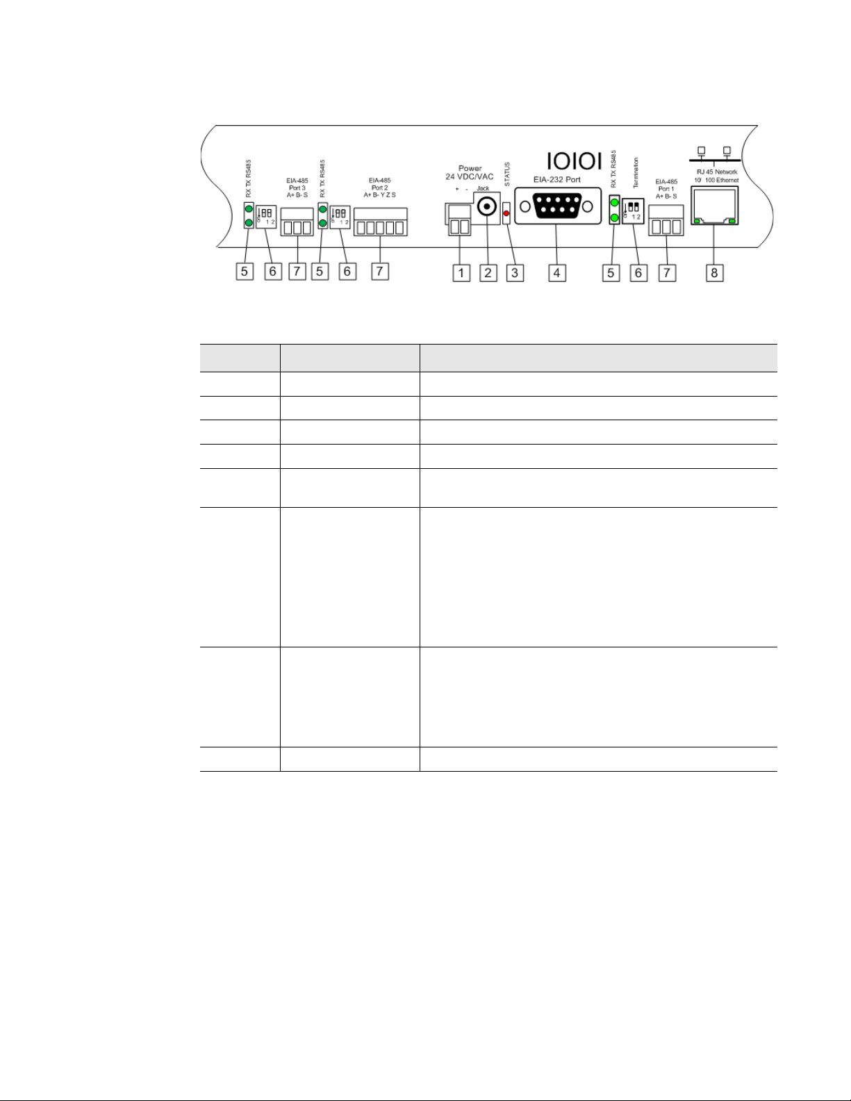
1.2.1 Rear Panel Indicators
The back of the Protocol Converter has the following indicators:
♦ Two indicators to show when data is being transmitted and received through the EIA-485
port (the Dual Port Protocol Converter contains three EIA-485 ports and three sets of
transmit-receive indicators). When data is either being transmitted or received, the status
lights will blink. If no information is being communicated, the lights are off.
♦ One status indicator to show when the Protocol Converter is booting up or has an alarm
condition. If neither of these is occurring, the light is off.
Figure 1.1
Protocol Converter Indicators
Status Indicator
Status LED Flashing red: Boot-up sequence
Solid red: Alarm condition
EIA-485 TX Flashing: Data is being transmitted.
EIA-485 RX Flashing: Data is being received.
Table 1.1
LED Indicator Descriptions
12 Protocol Converter User Guide 800.518.1519
Page 13
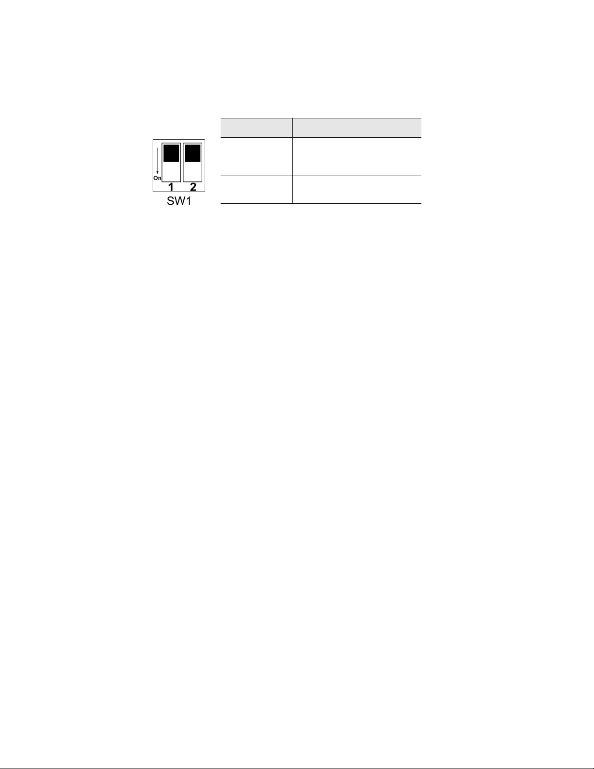
1.2.2 Terminal Block Designations
1 Product Overview
Figure 1.2
Item No. Item Description
Table 1.2
Locations of Terminals
1
2
3
4
5
6
7
8
Power 24 VDC/VAC Power terminal block
Jack Power connector for wall wart adapter
Status Status LED
EIA-232 Port DB9 female connector
RX TX EIA-485 LED Receive/Transmit status LED. Dual Port Protocol
EIA-485 Termination
switch
EIA-485 port Dual Port Protocol Converter contains two additional
RJ45 Ethernet port 10/100 BaseT connector
Terminal Block Designations
Converter contains two additional sets of LEDs.
Dual Port Protocol Converter contains two additional
sets of switches; EIA-485 Port 2, the 5-pin port, can be
configured as a 2-wire (half-duplex) or 4-wire (fullduplex) connection.
Ports 1 and 3: Switch 1 - unused; Switch 2 - On = 100
Ohm termination
Port 2: Switch 1 -Duplex (On = 4-wire; Off = 2-wire);
Switch 2 - On = 100 Ohm termination
EIA-485 ports. Port 2 (the middle port) can be
configured as a 2-wire or 4-wire connection. In addition
to all other supported protocols, Port 3 (the left most
port) of the Dual Port Protocol Converter is BACnet MS/
TP capable (Slave only).
rletech.com Protocol Converter User Guide 13
Page 14
1 Product Overview
1.2.3 SW1 Switch Settings
Switch Setting
SW1-1 Dual Port Protocol
Converter only: Duplex
(On = 4-wire; Off = 2-wire)
SW1-2 EIA-485 Termination
(On=100 Ohm termination)
Table 1.3
Status Indicator Descriptions
14 Protocol Converter User Guide 800.518.1519
Page 15
CHAPTER 0INSTALLATION
2.1. Register the Protocol Converter
Go to http://www.rletech.com/ and enter the requested information in the Product Registration
form. Submit the form to register your product.
C HAPTER
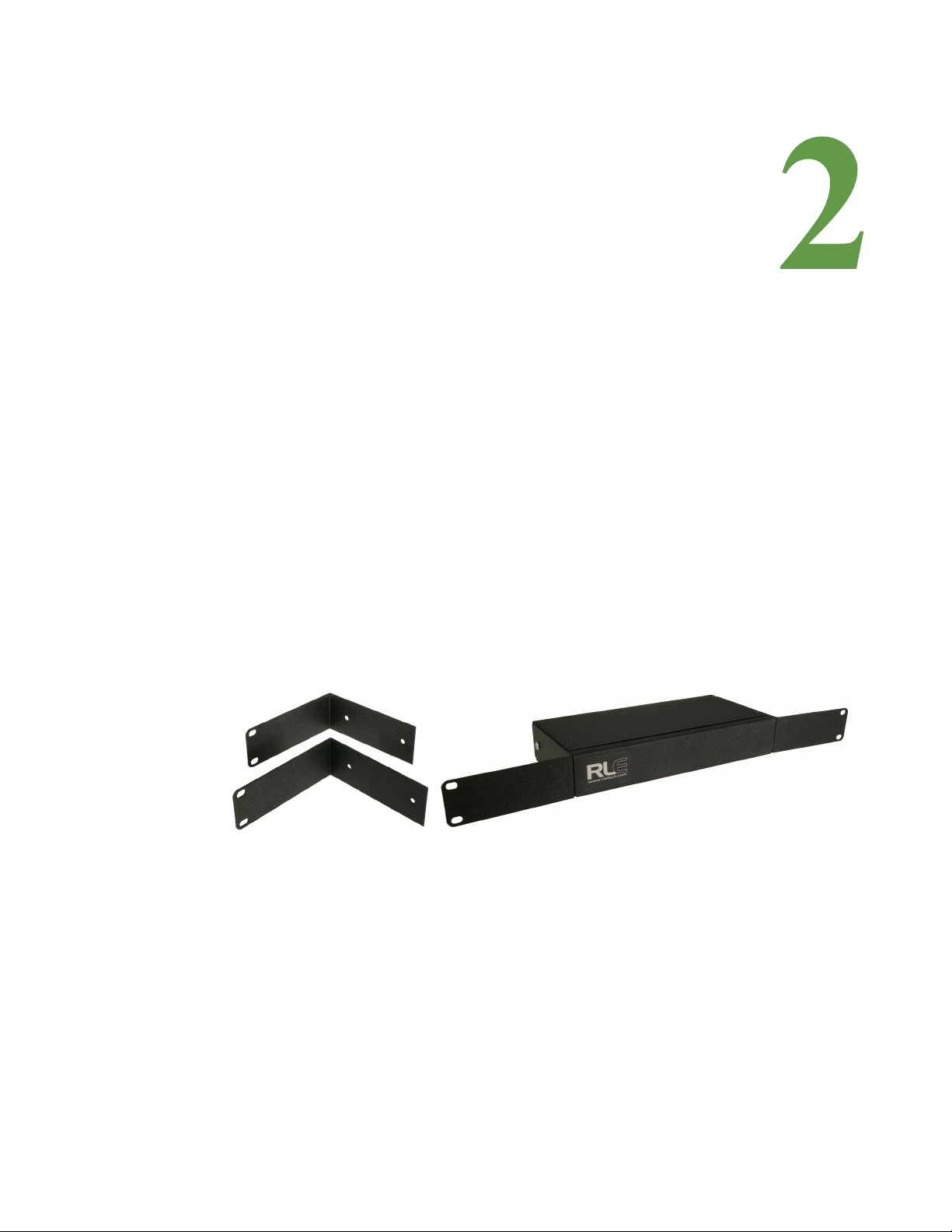
2.2. Mount the Protocol Converter
The Protocol Converter comes with mounting brackets to allow the unit to be installed in a
19-inch (0.48m) rack.
1 Using the screws provided, attach the mounting brackets to the sides of the device.
Figure 2.1
NOTE The brackets can be reversed so the other side of the Protocol Converter is facing outward.
2
Install the Protocol Converter in the rack.
3 Use the proper anchoring method to mount the Protocol Converter securely in the rack.
Protocol Converter with Mounting Brackets
rletech.com Protocol Converter User Guide 15
Page 16
2 Installation
2.3. Wire the Protocol Converter
If you plan to use the EIA-485 port for Modbus RTU communication, RLE Technologies
recommends an 18 AWG shielded, twisted-pair stranded copper wire for the connection. RLE
recommends no more than 2,000 feet (609.6m) of wire at this specification. If longer runs are
needed, contact RLE Technologies for application guidance.
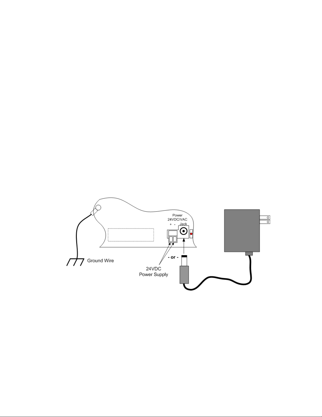
2.3.1 Power Supply & Ground Connections
To provide power and ground connections to the Protocol Converter:
1 Connect an 18 AWG ground wire from the ground terminal to a suitable earth ground.
2 Connect power to the Protocol Converter in one of two ways, as shown in Figure 2.2:
a Plug the wall adapter (provided) into the power jack on the Protocol Converter and into a
UPS outlet.
b Connect a dedicated 24VDC power supply to the + and - terminals to the left of the
power jack.
IMPORTANT RLE Technologies recommends powering the Protocol Converter from a UPS (uninterruptible
power supply) so the Protocol Converter can send alarm notifications during a power outage.
Figure 2.2
24VDC Power Supply Connection
16 Protocol Converter User Guide 800.518.1519
Page 17
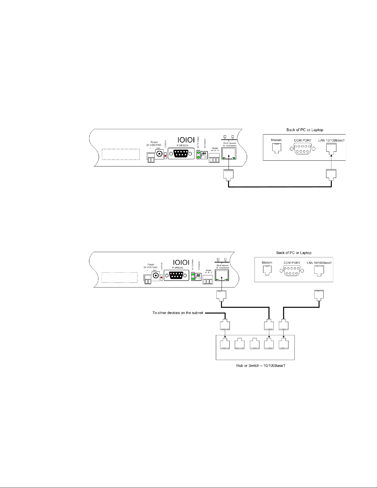
2.3.2 RJ45 Ethernet Connection
The Protocol Converter has an internal 10/100BaseT Ethernet port used to configure the
Protocol Converter. The Ethernet port supports Web browser access, BACnet, Modbus,
SNMP, and SMTP (email).
Direct Connection
To make a direct connection between the Protocol Converter and a computer or laptop using
the crossover cable - the blue cable with yellow connectors provided with the device.
2 Installation
Figure 2.3
Protocol Converter Ethernet Connection to a PC Using a Crossover Cable
Subnet Connection
To connect the Protocol Converter on a subnet using a hub or switch and straight-through
CAT5 cables, see Figure 2.4.
Figure 2.4
rletech.com Protocol Converter User Guide 17
Protocol Converter Ethernet Connection to a PC on a Subnet
Page 18
2 Installation
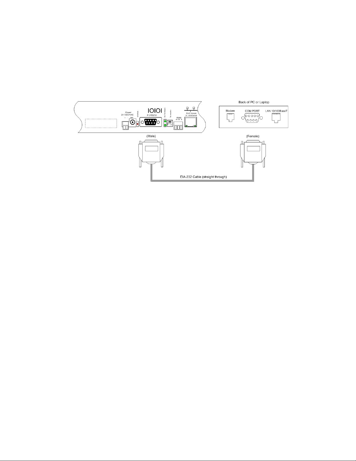
2.3.3 EIA-232 COM Connection
The EIA-232 port can be connected to a PC for IP configuration, firmware downloads, and
troubleshooting.
NOTE The EIA-232 is typically only used as a temporary connection.
Connect the straight through, 9-pin, serial cable as shown.
Figure 2.5
EIA-232 COM Connection
18 Protocol Converter User Guide 800.518.1519
Page 19
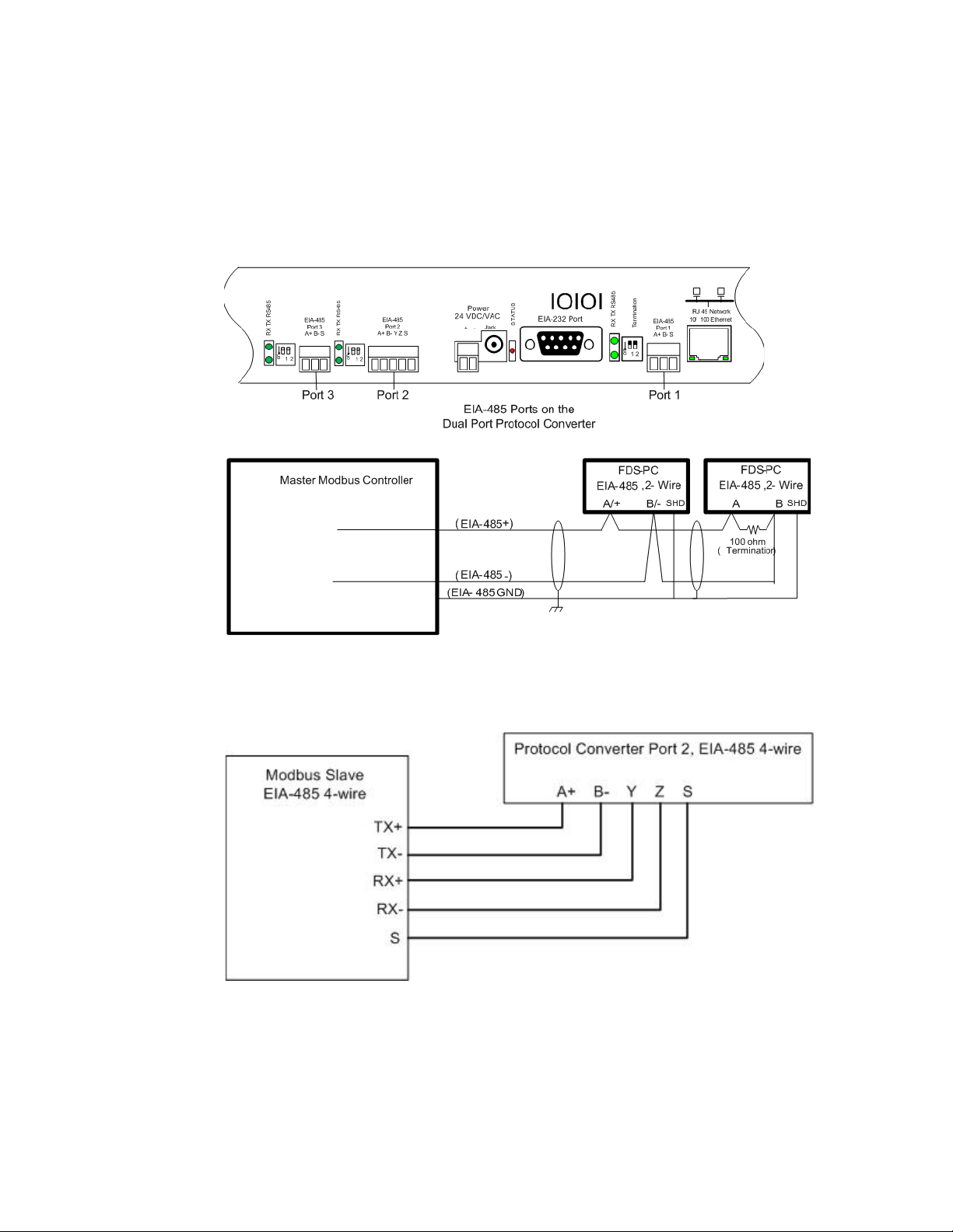
2.3.4 Modbus EIA-485 Connections
The Protocol Converter can function as a Modbus Slave or Modbus Master over an EIA-485
hardware connection. The Dual Port Protocol Converter contains three EIA-485 ports, and
EIA-485 Port 2 can be configured as either a 2-wire or 4-wire connection by wiring the port
appropriately and turning on the Duplex DIP switch. See Table 1.2 and Table 1.3 on page 14
for information about configuring this port.
2 Installation
Figure 2.6
Figure 2.7
EIA-485 Connection, 2-wire
EIA-485 Connection, 4-wire
rletech.com Protocol Converter User Guide 19
Page 20

2 Installation
20 Protocol Converter User Guide 800.518.1519
Page 21

C HAPTER
CHAPTER 0CONFIGURATION
The Protocol Converter allows you to view and configure slave devices and slave registers
over the Web. To access the Web interface, you must first set up the Protocol Converter to
communicate over the Internet. To set the IP address, see “Configure Communications” on
page 21.
Follow the order of the sections in this chapter to completely configure the slave devices,
registers, and the Protocol Converter.
3.1. Configure Communications
The Protocol Converter will not communicate over a user’s network the first time it is
connected to the network. At the factory, the Protocol Converter is set with a default IP
address of 10.0.0.188 and Subnet Mask: 255.255.255.0.
You must change this default address to an IP address that corresponds with your network
before the Protocol Converter can communicate over the network. Use one of these vehicles to
change the IP address:
♦ A Web browser
♦ The EIA-232 interface
rletech.com Protocol Converter User Guide 21
Page 22

3 Configuration
WARNING
3.1.1 Set the IP Address Using a Web Browser
Unless you are familiar with setting the IP address, consult your IT department
before attempting this procedure.
To use a Web browser to set the Protocol Converter's IP address:
1 Plug a crossover network cable into the laptop or workstation that will be used to configure
the Protocol Converter.
2 Write down the computer's current IP address and Subnet Mask.
IMPORTANT You will need to change the computer's IP address and Subnet Mask back to the original
settings after changing the IP address and Subnet Mask for the Protocol Converter.
3
Change the IP address and Subnet Mask of the computer from its existing address to one
that will allow it to communicate with the Protocol Converter, such as 10.0.0.180.
NOTE It may be beneficial to set the IP address to one that is one number different from the Protocol
Converter's IP address. Consult the computer's manual or your IT department before
attempting this procedure.
4
Connect the other end of the network cable to the Ethernet port on the back of the Protocol
Converter.
5 Access the Protocol Converter through a Web browser by typing the IP address
(10.0.0.188) into the location bar.
6 When prompted, enter the Protocol Converter user name (fds). There is no default
password; leave this field blank.
Figure 3.1
Protocol Converter Login Screen
Once you enter the correct user name, the Home page displays.
22 Protocol Converter User Guide 800.518.1519
Page 23

3 Configuration
7 Select the Configuration link from the top bar, then select the Network and Web link from
the Configuration menu.
Figure 3.2
8
On the Network and Web page, change the IP address, Subnet Mask (Net Mask), and
Protocol Converter Login Screen
Default Gateway (Def Route) to one provided by your network administrator.
Figure 3.3
9
Press the Submit Changes button.
Change the IP Address Through the Web Interface
The Protocol Converter saves the new IP address, Subnet Mask, and default Gateway and
then reboots.
10Change the IP address of the computer back to its original IP address.
11If the computer was configured as DHCP (the network domain controller assigns an IP
address) return it to this state. This procedure might require assistance from your IT
department, or you might need to consult the computer's manual.
The computer and the Protocol Converter are both configured to communicate on the
network. Both should be accessible via the network.
12Connect the computer and the Protocol Converter to the network.
13From the computer's Web browser, type the new IP address of the Protocol Converter.
Enter the user name and password as stated in step 8 to verify network access to the
Protocol Converter.
rletech.com Protocol Converter User Guide 23
Page 24

3 Configuration
3.1.2 Set the IP Address Using an EIA-232 Connection
To use the EIA-232 interface to set the Protocol Converter’s IP address:
1 Connect the EIA-232 port on the Protocol Converter to a terminal or PC running terminal
emulation software (HyperTerminal) with a 9-pin, male-female, straight-through serial
cable.
2 Set the appropriate communication port to 9600 baud, no parity, 8 data bits, 1 stop bit,
(9600/N/8/1), and no software or hardware flow command.
3 Once the terminal emulation software starts, press Enter on the keyboard.
The Protocol Converter’s boot prompt appears, (FDS_PC>).
NOTE If the Protocol Converter’s boot prompt does not appear, check the communication settings
and make sure the unit is powered on.
4
From the boot prompt, type IP, one space, and the new IP address for the Protocol
Converter, then press Enter.
Example:
IP 192.168.103.211
The Protocol Converter reboots after the IP address is changed.
5 If you need to change the subnet mask: From the boot prompt type NM, one space, and the
new Subnet Mask address for the FDS-PC, then press Enter.
Example:
NM 255.255.255.0
The Protocol Converter reboots after the Subnet Mask is changed.
6 If you need to change the default gateway: From the boot prompt, type DG, one space, and
the Default Gateway address for the Protocol Converter, then press Enter.
Example:
DG 192.168.103.1
The Protocol Converter reboots after the Default Gateway is changed.
The Protocol Converter IP address is now set, and it can be accessed through a Web
browser using the new IP address. The default username is fds. There is no password; leave
that field blank.
24 Protocol Converter User Guide 800.518.1519
Page 25

3.2. Log In to the Protocol Converter
Once the IP address for the Protocol Converter has been set as described in 3.1., “Configure
Communications” on page 21, you can log in to the Protocol Converter:
Open a Web browser and type the Protocol Converter’s IP address (default is 10.0.0.188) into
the location bar.
When prompted, enter the Protocol Converter user name (default is fds).
3 Configuration
Figure 3.4
NOTE There is no default password; if you have not set a password, leave this field blank.
Protocol Converter Login Screen
Once you enter the correct user name (and password), the Devices page displays.
The Devices page of a fully configured Protocol Converter is shown below. The table on this
page displays a list of configured slave devices and their status.
Figure 3.5
rletech.com Protocol Converter User Guide 25
Protocol Converter Devices (Home) Page
Page 26

3 Configuration
Each device’s status is color coded.
Figure 3.6
Note: The color codes are also available in the Help section of the Protocol Converter interface.
Protocol Converter Color Codes
Click on an individual device number to view individual information being polled from that
device to the Protocol Converter.
Figure 3.7
Register Status Example
Visit the RLE website for additional documentation and troubleshooting information - click on
the RLE Technologies link on the bottom right corner of the web interface.
26 Protocol Converter User Guide 800.518.1519
Page 27

3.3. Configure Network and Web Properties
Use the Configuration section of the Protocol Converter’s web interface to configure basic
device functionality. The Network and Web link displays the MAC address and allows you to
fill in the IP Address, Net Mask, Default Router (Default Gateway), Passwords, and Refresh
rate.
In the user interface, go to Configuration>Network and Web. Edit the fields appropriately.
3 Configuration
Figure 3.8
Option Description
IP Address The Protocol Converter is configured at the factory with a default IP
Net (Subnet)
Mask
Def (Default)
Route
Web
Password
Read Only
Table 3.1
Network and Web Configuration Screen
Address of 10.0.0.188. If you’d like to change the IP address, do so here.
Default: 10.0.0.188
The Protocol Converter is configured at the factory with a default Subnet
Mask of 255.255.255.0. Edit this field as necessary.
Default: 255.255.255.0
The Protocol Converter is configured at the factory with a default Gateway
Route of 10.0.0.1. Edit this field as directed by your IT department.
Default: 10.0.0.1
The Protocol Converter can be configured with two passwords - the read
only password allows users to access the web interface but not to edit any
of the configurable settings.
Specify an alphanumeric value up to 16 characters.
Network and Web Configuration Fields
rletech.com Protocol Converter User Guide 27
Page 28

3 Configuration
Option Description
Web
Password
Read/Write
Web Refresh
Rate
Table 3.1
Network and Web Configuration Fields (continued)
The Protocol Converter can be configured with two passwords - the read/
write password allows users to access the web interface and to edit all
settings.
Specify an alphanumeric value up to 16 characters.
This integer value represents how long the system waits until it updates
the Web interface with current data. To change the rate, click in the field
and type the desired amount of time (in seconds). The default refresh rate
is set to 0, which means the Protocol Converter will not refresh at all. If you
want the system to automatically refresh, set the refresh rate to a positive
number greater than 0. The minimum recommended refresh rate is five
seconds. A slower rate could cause errors that prevent the system
from functioning properly.
28 Protocol Converter User Guide 800.518.1519
Page 29

3.4. Set and Synchronize the Clock
When you’re configuring the Protocol Converter, be sure to set and synchronize the Protocol
Converter’s clock. This ensures all time-stamped events are accurate. Do this on the
Configuration>Clock screen.
3 Configuration
Figure 3.9
Option Description
Date Enter the date in mm/dd/yy format.
Time Enter the time in hh:mm:ss format (24-hour clock).
Table 3.2
Clock Configuration Page
Clock Fields
rletech.com Protocol Converter User Guide 29
Page 30

3 Configuration
3.4.1 Network Time Protocol (NTP)
Network Time Protocol (NTP) is used to synchronize clocks of computer systems. NTP
synchronizes the time of a computer or device (the Protocol Converter) to another computer or
referenced time source. NTP maintains a high level of accuracy and reliability in time stamped
events. NTP is found on the Configuration>Network Time Protocol screen.
Figure 3.10
Option Description
Network Time (NTP)
Server
Update Interval
Select Time Zone
Daylight Savings
Time
DST Begin Date
DST End Date
Table 3.3
Network Time Protocol (NTP) Configuration
The IP address or hostname of the Network Time Protocol Server
with which the Protocol Converter will synchronize. Public NTP
Servers include us.pool.ntp.org and time.nist.gov.
Default setting: blank
This designates how often you’d like the Protocol Converter to
access and synchronize with the NTP server.
This can be set from 5 to 1440 minutes. Enter 0 to disable this
feature.
Default setting: 0 (disabled)
Select the time zone in which the Protocol Converter resides.
Select the time at which Daylight Savings Time goes into effect in
your time zone. Typically, this is 2:00 A.M.
Enter the day Daylight Savings Time begins at your location.
Enter the day Daylight Savings Time ends at your location.
NTP (Network Time Protocol) Fields
30 Protocol Converter User Guide 800.518.1519
Page 31

3.5. Configure Slave Devices
Once the basic functionality of the Protocol Converter has been configured, you’re ready to
configure slave devices. You can configure up to 32 slave devices to the Protocol Converter.
1 From the top navigation bar on the Protocol Converter’s home page, click the Device
Configuration link.
The Device Configuration page is divided into four subpages - eight slave devices can be
configured on each page. These slave devices can be configured for Modbus RTU/485,
Modbus TCP, SNMP V1, BACnet/IP, SNMP-RFC1628, or SNMP V2C.
3 Configuration
Figure 3.11
2
To configure a slave device, enter the appropriate information for the communication
Device Configuration Screen
protocol used by that device. Only the applicable fields for each communications protocol
will appear. Configurable fields include:
Option Description
Access Mode Use the drop-down to select Modbus-RTU/485, Modbus
TCP, SNMP V1, BACnet/IP, SNMP-RFC-1628, or SNMP
V2.
Note: RFC-1628 access mode is available for BACnet/IP
only.
EIA-485 Port Select the appropriate port.
Modbus/TCP Poll Rate Select the number of packets per second - 10, 5, or 1.
Table 3.4
rletech.com Protocol Converter User Guide 31
Device Configuration Fields
Page 32

3 Configuration
Option Description
Modbus Slave Address /
Unit Identifier
IP Address Enter the IP address of the device being polled for Modbus
Device Name Enter a descriptive label to identify the slave device you are
Modbus Bulk Poll Enabled,
Start Reg & Num Regs
SNMP Community This value defines the community/string used to obtain
BACnet Device Instance,
dnet & dadr
A numeric value that indicates the slave address for
Modbus communications.
Type an integer ranging from 1 to 254.
If Modbus communications will not be used, leave this
value at 0.
TCP, SNMP, or BACnet/IP slave data.
polling. This label can contain up to 30 characters.
If you’re using Modbus and would like to poll multiple
registers at one time, check this box.
Start Reg: The number of the register where bulk polling
begins.
Num Reg: The number of registers that are polled in the
bulk polling event.
data. This value is alphanumeric and MUST match the
comm string in the slave unit - for example, public or
rletech.
Enter the number or Device ID number assigned to the
slave unit - for example 500. This number MUST match the
device ID of the slave unit.
If you’re using a BACnet routed device, you’ll need to enter
some additional information:
dnet: Enter the destination BACnet network (1-65535).
dadr: This is the BACnet destination address (MSTP).
If you have a MS/TP routed device, enter a decimal
number from 1-254.
If you have an IEEE802.3 routed device, enter a MAC
address in hex (for example, 00:90:5b:01:02:0c)
Table 3.4
3 Repeat this process for each slave device you want to configure.
4 If desired, use the Download XML link located in each device configuration box to save the
Device Configuration Fields (continued)
device configuration and copy it to another device. Use the Upload XML link to upload the
configuration to another device. See “Save a Device Configuration (.xml) File” on page 63
and “Load a Device Configuration (.xml) File” on page 64 for details.
32 Protocol Converter User Guide 800.518.1519
Page 33

3.6. Configure Device Registers
Once the desired slave devices have been configured on the Protocol Converter, you can
program registers to those slave devices for the proper information to be polled. First, you can
select whether or not to enable write operations to the slave devices, then you can program the
registers.
NOTE You can also delete the Protocol Converter’s entire register set. Make sure to consider this
operation carefully before carrying it out.
3.6.1 Enable Write Operations to Devices
To enable the ability to write values to Modbus, SNMP, and BACnet device registers:
1 Click the Configuration link in the menu bar. From the Configuration menu, click the
EIA-485/Modbus/BACnet-MSTP Ports link.
3 Configuration
2 In the top section of the EIA-485/Modbus/BACnet-MSTP Ports page, select Yes to enable
the Device Write option:
The write operations are generated via Modbus preset single-register commands, SNMP
sets, and BACnet write-property operations. Refer to the following sections on configuring
Modbus, SNMP, and BACnet registers for more information about generating write
operations through the Protocol Converter’s user interface.
rletech.com Protocol Converter User Guide 33
Page 34

3 Configuration
3.6.2 Register Configuration Web Pages
Access the Register Configuration page by clicking on the Registers link in the menu bar.
1 Click on the register number to configure individual registers.
Figure 3.12
Register Configuration Page
The configuration page for that register displays. Notice that the Unit number corresponds
to the Device number listed on the Register Link page.
2 Enter the necessary information for the register type you are configuring. See Sections 3.6.3
to 3.6.5 for more information.
3 Click Submit.
The Protocol Converter updates the information and displays the information that applies to
that unit (Modbus, SNMP, or BACnet).
34 Protocol Converter User Guide 800.518.1519
Page 35

3.6.3 Modbus Register Configuration
If you are configuring a Modbus device, the register configuration page looks like this:
3 Configuration
Figure 3.13
1
Type an appropriate value in each field, or choose the value from the drop-down.
Option Description
Unit This is the unit number of the register you’re configuring.
Modbus Register The Modbus register to be polled by the Protocol Converter
Register Type The register type. Choose Unsigned Integer, Signed
Table 3.5
rletech.com Protocol Converter User Guide 35
Modbus Register Configuration
to that specific slave. The Protocol Converter can poll Coil
registers (1x,) Status registers (2x), Input registers (3x),
and Holding registers (4x). Type a value in the range of
0000 to 49999 or 410000 to 465535.
integer, Long, Float, Alarm Bit / ON=ALARM, Alarm Bit /
OFF=ALARM, Status Bit, Coil Status, Input Status, or
Int64.
Modbus Register Configuration Page Options
Page 36

3 Configuration
Option Description
Bitflag The proper bit flag to be used for this particular register.
Choose values from :00 to :15.
Modbus Word Order Determines the way the register is read by the Protocol
Converter. Choose from Big-Endian (Left to Right) or LittleEndian (Right to Left).
Gain The gain value of the raw data being received. Set this
value only if necessary.
Offset The offset value to the calculated reading for the register.
Set this value only if necessary.
Label Designate a name (label) for the register being configured.
Labels can be up to 30 alphanumeric characters in length.
HTML Display This option allows you to choose how the value is
displayed on the register page. Choose from Integer (whole
number) or Float (a number plus a decimal).
Threshold 1 Indicates the value that, when reached or exceeded,
causes the Protocol Converter to trigger an alarm.
Specify if the alarm should occur when the reading is less
than (<), Equal to (=) or greater than (>) the specified
threshold value.
Threshold 2 Indicates the value that, when reached or exceeded,
causes the Protocol Converter to trigger an alarm.
Specify if the alarm should occur when the reading is less
than (<), Equal to (=) or greater than (>) the specified
threshold value.
Alarm Delay The amount of time, in seconds, that passes between the
time an alarm condition occurs and the time the Protocol
Converter issues an alert.
The default value of 0 indicates no delay.
Offline Delay The amount of time, in seconds, that elapses before the
Protocol Converter considers the register to be stalled or
offline.
The default value of 0 indicates no delay.
Current Age Indicates the amount of time, in seconds, since the
Protocol Converter last received an updated value.
Local Modbus Int Register The Modbus Integer data (whole number) used by a master
device polling the Protocol Converter.
Local Modbus Float
Register
Table 3.5
36 Protocol Converter User Guide 800.518.1519
Modbus Register Configuration Page Options
The Modbus Float data (number with decimal) used by a
master device polling the Protocol Converter.
Page 37

3 Configuration
Option Description
BACnet Instance The number used by a BACnet master for polling data from
the Protocol Converter.
Possible values include Analog Instance (AI) or Binary
Instance (BI).
BACnet Engineering Units In the BACnet ASHRAE standard, numbers correlate with
units of measure. Refer to the BACnet ASHRAE standard
for more information.
BACnet COV Client
(COV - Change of Value)
BACnet COV SPID Enter the Subscriber Process Identifier.
BACnet COV Increment Amount that the present value of a point needs to change
BACnet COV Period Interval, in seconds, between polling operations.
SNMP register/Table OIDs The OID (object identifier) being polled from the SNMP
The IP address of the BACnet master that is polling the
FDS-PC.
You’ll also need to designate if it should be Confirmed or
Unconfirmed.
Confirmed: When a change of value is sent to the device, it
will look for an acknowledgement of the change to be sent
in response. If no acknowledgement is received, the
change will be sent again. This cycle will repeat until an
acknowledgement is received.
Unconfirmed: A change of value is sent, and the device
doesn’t look for an acknowledgement.
Select the Confirmed or Unconfirmed radio button to
indicate your preference.
before the change of value message is initiated to the
BACnet master.
software. The Protocol Converter displays the OIDs used
for Integer data, Float data, and the Label assigned.
SNMP Modbus Device
Register/Table OIDs
Table 3.5
2 Click Submit Changes located in the upper left hand corner of the web page.
3 Once the changes have been accepted, click the Next>> link in the bottom navigation bar to
Modbus Register Configuration Page Options
Formatted to
BASE.DEVICENUMBER.REGISTERNUMBER where
BASE is the OID for this table, DEVICENUMBER is the
device’s number in the Protocol Converter (1-32) and the
REGISTERNUMBER reflects the appropriate device point
address.
configure the next register.
You can also click the First, <<Prev, Last, or End links to go to those locations in the list of
registers.
Figure 3.14
rletech.com Protocol Converter User Guide 37
Register Configuration Navigation
Page 38

3 Configuration
4 Write a specific value to a Modbus register by clicking the Manual Preset Single Register
link on the individual register pages. This option is only available for writeable Modbus
registers (40001 and above).
Figure 3.15
Modbus Manual Preset Single Register Link
When you click this link, the Modbus Preset Single Register webpage displays.
Figure 3.16
5
Enter the new value for the register in the New Value box and click the Submit Changes
Modbus Preset Single Register Webpage
button.
Click the Return link to go back to the register configuration page.
38 Protocol Converter User Guide 800.518.1519
Page 39

3.6.4 SNMP Register Configuration
If you are configuring an SNMP device, the register configuration page looks like this:
3 Configuration
Figure 3.17
1
Type an appropriate value in each field, or choose the value from the drop-down.
Option Description
SNMP Get OID The OID (object identifier) the Protocol Converter uses to
OID Type The object identifier type. Currently, the Protocol Converter
Gain The gain value of the raw data being received (set only if
Offset The offset value of the calculated reading to the register.
Label Designate a name (label) for the register being configured.
HTML Display This option allows you to choose how the value is
Table 3.6
SNMP Register Configuration
gather the correct integer data from the SNMP device
being polled.
can poll Integer data.
necessary).
Labels can contain up to 30 alphanumeric characters.
displayed on the register page. Choose from Integer (whole
number) or Float (number plus decimal).
SNMP Register Configuration Options
rletech.com Protocol Converter User Guide 39
Page 40

3 Configuration
Option Description
Threshold 1 Indicates the value that, when reached or exceeded,
causes the Protocol Converter to trigger an alarm.
Specify if the alarm should occur when the reading is less
than (<), Equal to (=) or greater than (>) the specified
threshold value.
Threshold 2 Indicates the value that, when reached or exceeded,
causes the Protocol Converter to trigger an alarm.
Specify if the alarm should occur when the reading is less
than (<), Equal to (=) or greater than (>) the specified
threshold value.
Alarm Delay The amount of time, in seconds, that passes between the
time an alarm condition occurs and the time the Protocol
Converter issues an alarm.
The default value of 0 indicates no delay.
Offline Delay The amount of time, in seconds, that elapses before the
Protocol Converter considers the register to be stalled or
offline.
The default value of 0 indicates no delay.
Current Age Indicates the amount of time, in seconds, since the
Protocol Converter last received an updated value.
Local Modbus Int Register The Modbus Integer data (whole number) used by a master
device polling the Protocol Converter.
Local Modbus Float Register The Modbus Float data (number with decimal) used by a
master device polling the Protocol Converter.
BACnet Instance The number used by a BACnet master for polling data from
the Protocol Converter.
Possible values include Analog Instance (AI) or Binary
Instance (BI).
SNMP register/Table OIDs The OID (Object Identifier) being polled from a SNMP
software. The Protocol Converter displays the OIDs used
for Integer data, Float data and the Label assigned.
SNMP modbus Device
Register/Table OID
Formatted to
BASE.DEVICENUMBER.REGISTERNUMBER where
BASE is the OID for this table, DEVICENUMBER is the
device’s number in the Protocol Converter (1-32) and the
REGISTERNUMBER reflects the appropriate device point
address.
Table 3.6
SNMP Register Configuration Options
2 Click Submit Changes located in the upper left hand corner of the web page.
3 Once the changes have been accepted, click on Next>> link at the bottom of the page.
40 Protocol Converter User Guide 800.518.1519
Page 41

3 Configuration
You can also click the First, <<Prev, Last, or End links to go to those locations in the list of
registers.
Figure 3.18
4
Write a specific value to an SNMP register by clicking the SNMP Set Register link on the
Register Configuration Navigation
individual register pages.
Figure 3.19
SNMP Set Register Link
When you click this link, the SNMP Set Register webpage displays.
Figure 3.20
5
Enter the new value for the register in the New Value box and click the Submit Changes
SNMP New Value Field
button.
Click the Return link to go back to the register configuration page.
rletech.com Protocol Converter User Guide 41
Page 42

3 Configuration
3.6.5 BACnet Register Configuration
If you are configuring a BACnet device, the register configuration page looks like this:
Figure 3.21
1
Type an appropriate value in each field, or choose the value from the drop-down.
Option Description
BACnet Instance The Instance number used by the Protocol Converter to
Instance Type Select the type of BACnet instance from the drop-down
Gain The gain value of the raw data being received if needed.
Offset The offset value of the calculated reading to the register.
Label Designate a name (label) for the register being configured.
Table 3.7
BACnet Register Configuration
poll the desired data from that BACnet device.
menu. Choose Analog Input (AI), Analog Output (AO),
Analog Value (AV), Binary Input (BI), Binary Output (BO),
Binary Value (BV), Multistate Input (MI), Multistate Output
(MO), or Multistate Value (MSV).
Calculate as follows: (Sensor High Range Value - Sensor
Low Range Value) / 4
Calculate as follows: Sensor Low Range Value - Gain
Labels can contain up to 30 alphanumeric characters.
BACnet Register Configuration Options
42 Protocol Converter User Guide 800.518.1519
Page 43

3 Configuration
Option Description
HTML Display This option allows you to choose how the value is
displayed on the register page. Choose from Integer (whole
number) or Float (a number plus a decimal).
Threshold 1 Indicates the value that, when reached or exceeded,
causes the Protocol Converter to trigger an alarm.
Specify if the alarm should occur when the reading is less
than (<), Equal to (=) or greater than (>) the specified
threshold value.
Threshold 2 Indicates the value that, when reached or exceeded,
causes the Protocol Converter to trigger an alarm.
Specify if the alarm should occur when the reading is less
than (<), Equal to (=) or greater than (>) the specified
threshold value.
Alarm Delay The amount of time, in seconds, that passes between the
time an alarm condition occurs and the time the Protocol
Converter issues an alert.
The default value of 0 indicates no delay.
Offline Delay The amount of time, in seconds, that elapses before the
Protocol Converter considers the register to be stalled or
offline.
The default value of 0 indicates no delay.
Current Age Indicates the amount of time, in seconds, since the
Protocol Converter last received an updated value.
Local Modbus Int Register The Modbus Integer data (whole number) used by a master
device polling the Protocol Converter.
Local Modbus Float Register The Modbus Float data (number with decimal) used by a
master device polling the Protocol Converter.
BACnet Instance The number used by a BACnet master for polling data from
the Protocol Converter.
Possible values include Analog Instance (AI) or Binary
Instance (BI).
SNMP Register/Table OID The OID (Object Identifier) being polled from a SNMP
software. The Protocol Converter displays the OIDs used
for Integer data, Float data and the Label assigned.
SNMP Modbus Device
Register/Table OID
Formatted to
BASE.DEVICENUMBER.REGISTERNUMBER where
BASE is the OID for this table, DEVICENUMBER is the
device’s number in the Protocol Converter (1-32) and the
REGISTERNUMBER reflects the appropriate device point
address.
Table 3.7
BACnet Register Configuration Options (continued)
2 Click Submit Changes located in the upper left hand corner of the web page.
rletech.com Protocol Converter User Guide 43
Page 44

3 Configuration
3 Once the changes have been accepted, click on Next>> link at the bottom of the page.
You can also click the First, <<Prev, Last, or End links to go to those locations in the list of
registers.
Figure 3.22
4
Write a specific value to a BACnet register by clicking the Write Value link on the
Register Configuration Navigation
individual register pages.
Figure 3.23
BACnet Write Value Link
When you click this link, the BACnet Analog Value Write webpage displays.
Figure 3.24
5
Enter the new value for the register in the New Value box and click the Submit Changes
BACnet Analog Value Write Field
button.
Click the Return link to go back to the register configuration page.
44 Protocol Converter User Guide 800.518.1519
Page 45

3.6.6 Delete All Registers
If you need to reconfigure the Protocol Converter for a new application, you can delete the
entire register set.
3 Configuration
IMPORTANT Consider the Delete All Registers option carefully and use it with caution. You should
use this option only if you need to reconfigure the Protocol Converter for a new
application.
To delete all programmed registers:
1 In the user interface, go to Configuration>System.
The System web page displays.
Figure 3.25
2
Click the Delete All Registers button.
System Page—Delete All Registers
A pop-up displays so you can confirm the delete operation.
3 If you are certain you want to delete all programmed registers, click OK. Otherwise, click
Cancel.
When you click OK, the registers are immediately deleted.
rletech.com Protocol Converter User Guide 45
Page 46

3 Configuration
3.7. Set Communication Protocol Options
Set the Modbus, BACnet, or SNMP protocols as described in the following sections.
3.7.1 Modbus/EIA-485 Port Configuration
To configure the Modbus/EIA-485 port, use the top navigation bar to access the Configuration
screens. Select the EIA-485/Modbus/BACnet-MSTP Ports option and configure the fields
accordingly.
Figure 3.26
Option Description
Modbus/TCP/UDP Slave
Unit Identifier
Offline Startup Delay Amount of time, in minutes, that the Protocol Converter waits
Table 3.8
46 Protocol Converter User Guide 800.518.1519
EIA-485/Modbus/BACnet-MSTP Ports Configuration
Designate the TCP/UDP slave address in the range 1 to 254.
To disable this feature, leave the address set to 0.
before considering any slave device as offline after a power up.
EIA-485/Modbus/BACnet-MSTP Ports Configuration Options
Page 47

Option Description
3 Configuration
Max. EIA-485 Device
Response Time
This setting determines the allowable response time, in
seconds, from devices before the Protocol Converter times out.
Set a value in the range of 0.3 to 9.9 seconds. If the Protocol
Converter times out, an offline alarm will be triggered and the
device’s status color will change on the Protocol Converter’s
home page.
SNMP/BACnet/IP Device
Poll Rate
Modbus/TCP Open
Requests
Determines the rate, in packets per second, at which data is
sent. The drop-down provides selections of 1, 5, or 10.
Define the number of retries the Protocol Converter should
execute.
Device Write Enable Determines whether or not client write operations to the
Protocol Converter are translated, written to the specific server
device or register and then read back by the Protocol Converter
to update the local register data.
The write operations are generated via SNMP Sets, BACnet
Write-Property and Modbus Preset Single Register commands.
Select Yes to enable the Protocol Converter to perform write
operations. Default: Yes.
EIA-485 Port (1, 2, 3)
Function
EIA-485 Port (1, 2, 3)
Baud Rate
EIA-485 Port (1, 2, 3)
The port type for the EIA-485 port. Choose Modbus Slave or
Modbus Master.
Speed of the EIA-485 port. Choose 1200, 2400, 9600 (default),
or 19200. Ports 2 and 3 can also run at 38400 baud.
Select None (default), Even, or Odd for the Parity output.
Parity
EIA-485 Port (1, 2, 3) Stop
Select 1 or 2.
Bits
EIA-485 Slave Address An RTU address in the range 1 to 254. To disable transmission
on the EIA-485 port, leave the value at 0.
BACnet MS/TP Port 3
Number of BACnet masters allowed on the MS/TP network.
Max Master
Table 3.8
EIA-485/Modbus/BACnet-MSTP Ports Configuration Options
rletech.com Protocol Converter User Guide 47
Page 48

3 Configuration
3.7.2 BACnet Server Configuration
From the Configuration page, click the Bacnet link to configure the BACnet Server.
Figure 3.27
BACnet Server Configuration
Enter the following settings for the BACnet server:
Option Description
Device ID A numeric value that uniquely identifies each BACnet
Device on the network.
Device Name Designate a name for the device, up to 40 characters in
length.
Description Ad additional descriptive information about the device as
necessary, up to 40 characters in length.
Table 3.9
48 Protocol Converter User Guide 800.518.1519
BACnet Server Configuration Options
Page 49

3 Configuration
Option Description
UDP Port This is the user datagram protocol port, which is used by
applications to send messages to a device (in this case, the
Protocol Converter).
Enter 0 to specify port 47808 as the UDP port. If another
port is specified by your application, enter a new port
number in this field.
Default setting: 0 (47808)
BACnet-MS/TP Port3 Max
Set the slave address, 1/127. 0 = slave only.
Master
Default setting: 0
BACnet/IP Read-Multiple Enable or disable this feature.
BACnet PICS link This link displays the protocol implementation conformance
statement (PICS). The PICS Web page shows general
BACnet capabilities of the device (for example, available
LAN options). An example of a BACnet PICS page is
shown in Figure 3.28.
Engineering Units Click this link to view a list of the units supported by the
device, coupled with their numerical BACnet identifiers.
BACnet/IP COV Clients This is a list of the BACnet clients that will receive a
notification when the Protocol Converter notes a change of
value (COV).
Configure these addresses on the Registers tab.
BACnet BBMD-BDT This feature is used by some BACnet masters for discovery
on different subnets. Enter information as applicable to
your application.
Table 3.9
BACnet Server Configuration Options (continued)
Figure 3.28
rletech.com Protocol Converter User Guide 49
BACnet PICS Information
Page 50

3 Configuration
3.7.3 SNMP
The SNMP Server configuration page allows you to set the System Name (displayed on the
home page), System Contact, and System Location. You can also set up communities that
allow multiple SNMP systems to access the Protocol Converter.
Note: To set up communities, you must know the IP address of the SNMP Management System and
the Community String. If necessary, contact your Technical Support department to obtain the
IP Address and Community String.
To configure the SNMP server, go to Configuration>SNMP. The SNMP (Server) web page
displays. Configure the fields as necessary.
Figure 3.29
SNMP Server Configuration
Option Description
System Name An alphanumeric name you assign to the Protocol
Converter for SNMP system integration.
System Contact The person or organization responsible for the Protocol
Converter.
System Location An alphanumeric description of the Protocol Converter's
location.
Get Community Name The name or type of password used by the SNMP server
for Get communications.
Set Community Name The name or type of password used for the SNMP server
that is writing to the Protocol Converter.
Trap Community Name The name or type of password used by the SNMP server
for Trap communications.
Trap Destination IP Address Enter up to four IP addresses to indicate where the
Protocol Converter should send Trap messages.
Table 3.10
SNMP Configuration Options
50 Protocol Converter User Guide 800.518.1519
Page 51

3.7.4 SMTP (Email)
Use the SMTP configuration section to set up the Protocol Converter’s communication to
email recipients. The Protocol Converter can send email to up to four recipients. Recipients
can include an exchange server using a distribution list, an email account, or a cell phone. The
Protocol Converter can also communicate via ESMTP (Authenticated) to mail servers
requiring a login name and password.
To access the SMTP configuration pages, go to Configuration>SMTP/DNS. The SMTP web
page displays.
3 Configuration
Figure 3.30
Option Description
Access Type Select None if email is not to be used or to temporarily
Primary DNS The first IP address used to communicate to a DNS server.
Secondary DNS The second IP address used to communicate to a DNS
Mail (SMTP) Server The IP address or host name of the mail server being used
Table 3.11
rletech.com Protocol Converter User Guide 51
SMTP Configuration
disable. Select LAN to enable email notification.
server.
by the Protocol Converter.
SMTP Configuration Options
Page 52

3 Configuration
Option Description
Mail Sender Address The email address used by the Protocol Converter to
communicate to the mail server.
Mail Subject Description to be displayed on the email notification subject
line.
Mail Recipient (1-4) The address for an email account, cell phone, or
distribution list.
SMTP Authentication
SMTP Username
SMTP Password
Table 3.11
SMTP Configuration Options
• None is used for no username or password being
required.
• Plain is used for standard Username and password
authentication.
• Login is used for certain mail servers. Do not use this
unless instructed by your IT department.
If you choose the Login radio button for SMTP Authentication, enter the username in this field.
If you choose the Login radio button for SMTP Authentication, enter the password in this field.
52 Protocol Converter User Guide 800.518.1519
Page 53

CHAPTER 0MODBUS COMMUNICATIONS
This chapter describes the Modbus communication protocol as supported by the Protocol
Converter Wireless System. The content includes details and information on how to configure
the Protocol Converter for communications via Modbus network.
4.1. Implementation Basics
C HAPTER
The Protocol Converter is capable of communicating via the half-duplex EIA-485 serial
communication standard. The Protocol Converter is configured to act as a slave device on a
common network. The EIA-485 medium allows for multiple devices on a multi-drop network.
The Protocol Converter is a slave only device and will never initiate a communications
sequence.
4.1.1 Modes of Transmission
The Modbus protocol uses ASCII and RTU modes of transmission. The Protocol Converter
supports only the RTU mode of transmission, with 8 data bits, no parity and one stop bit.
Every Modbus packet consists of four fields:
♦ Slave Address Field
♦ Function Field
♦ Data Field
♦ Error Check Field (Checksum)
4.1.1.1 Slave Address Field
The slave address field is one byte in length and identifies the slave device involved in the
transaction. A valid address range is between 1 and 254. The slave address is set on the
Modbus Device section of the Configuration page.
rletech.com Protocol Converter User Guide 53
Page 54

Modbus Communications
4.1.1.2 Function Field
The function field is one byte in length and tells the Protocol Converter which function to
perform. The supported functions are 03 (Read 4xxxx output registers).
4.1.1.3 Data Field
The data field of the request is a variable length depending on the function. The data fields for
the Protocol Converter are 16-bit registers, transmitted high order byte first (big-endian)
4.1.1.4 Error Check (Checksum) Field
The checksum field lets the receiving device determine if the packet has transmission errors.
The Protocol Converter RTU mode uses a 16-bit cyclic redundancy check (CRC-16).
4.1.2 Exception Responses
If a Modbus master sends an invalid command to the Protocol Converter or attempts to read an
invalid register, an exception response is generated. The response packet will have the high
order bit of the function code set to one. The data field of the exception response contains the
exception error code.
Table 4.1
Code Name Description
01 Illegal Function The function code is not supported
02 Illegal Data Address Attempt to access an invalid address
03 Illegal Data Value Attempt to set a variable to an invalid value
Exception Codes
4.2. Packet Communications for the Protocol Converter
This section covers the registers with the name and a brief description of each.
4.2.1 Function 03: Read Output Registers
To read the Protocol Converter parameter values, the master must send a Read Output
Registers request packet.
The Read Output Registers request packet specifies a start register and the number of registers
to read. The start register is numbered from zero (40001 = zero, 40002 = one, etc).
54 Protocol Converter User Guide 800.518.1519
Page 55

Modbus Communications
Table 4.2
Read Registers Request Packet Read Registers Response Packet
Slave Address (1 byte) Slave Address (1 byte)
03 (Function code) (1 byte) 03 (Function code) (1 byte)
Start Register (2 bytes) Byte count (1 byte)
# of registers to read (2 bytes) First register (2 bytes)
CRC Checksum (2 bytes) Second register (2 bytes)
Table 4.3
Register
40001 Integer Output Register for Integer data uint16 0-65535
42001 Float Output
Read Output Registers Packet Structure
…
CRC Checksum (2 bytes)
Output Registers
Name Description Units Range
Register for Float data Uint32 0-65535
* two registers need
4.3. RTU Framing
The example below shows a typical Query/Response from an Protocol Converter Wireless
System.
Table 4.4
Slave
Address
02 04 06 00 00 00 00 00 01 B5 A3
Response Sample
Function
Code
Count Bytes
of Data
Register
Data
Msb Lsb
Register
Data
Msb Lsb
Register
Data
Msb Lsb
CRC 16
“Lsb”
Slave address 2 responds to Function Code 4 with six bytes of hexadecimal data and ends with
CRC16 checksum.
Register Values:
40001 = 0000 (hex)
40002 = 0000 (hex)
40003 = 0001 (hex)
CRC 16
“Msb”
rletech.com Protocol Converter User Guide 55
Page 56

Modbus Communications
56 Protocol Converter User Guide 800.518.1519
Page 57

A PPENDIX
CHAPTER 0LOAD FIRMWARE & CONFIGURATION
FILES
You can perform the following firmware and configuration operations for the Protocol
Converter:
♦ Load different firmware to the Protocol Converter. RLE occasionally updates the firmware
to add enhancement or fix errors. Firmware updates are available on the RLE website at
www.rletech.com. Download appropriate firmware to an accessible place to upload to the
Protocol Converter via MIME or TFTP through a LAN connection. Firmware files have a
.bin extension.
♦ Make a backup of your custom configuration or copy the same configuration to several
Protocol Converters rather than having to change the settings manually on each unit. The
configuration settings are contained in a .cfg file.
♦ Make a copy of the configuration for a device so you can copy that configuration to other,
identical devices. The configuration settings for a device are contained in an .xml file.
A.1. Load Flash Firmware Using MIME
To update the firmware for the Protocol Converter using the MIME (multipurpose Internet
mail extensions) standard:
1 Go to the RLE website at http://www.rletech.com.
2 Locate the firmware (a .bin file) for the Protocol Converter. Using the same filename, save
it to a local disk.
IMPORTANT Do not change the name of the firmware file when you save it. Otherwise, the Protocol
Converter will not recognize the file.
3
In the Protocol Converter’s user interface, go to Configuration>System.
rletech.com Protocol Converter User Guide 57
Page 58

A Load Firmware & Configuration Files
The System webpage displays.
Figure A.1
Click the Browse button.
4
5 Locate and choose the firmware file (.bin) that you saved from the RLE website.
6 Click the Upload button.
System Page—Load Flash Firmware
While the firmware file loads, you’ll see the following confirmation message:
Figure A.2
Firmware Load Messages
When the file is loaded, the Protocol Converter reboots itself. The reboot process takes
approximately 60 seconds. After the reboot, the Home page displays.
7 Click the Identity link on the top bar and verify that the new file has been loaded.
Figure A.3
58 Protocol Converter User Guide 800.518.1519
Identity Link Showing Current Firmware Version
Page 59

A Load Firmware & Configuration Files
A.2. Load Flash Firmware Using TFTP
Loading firmware via TFTP (trivial file transfer protocol) requires a TFTP client. It may be
possible to download a free license TFTP client from the internet. Consult your IT department
to determine a compatible client program.
Before updating the firmware, the firmware flash application must be exited and then erased as
follows:
1 Verify that your PC and the Protocol Converter are on the same subnet (LAN) so the TFTP
client can access the Protocol Converter.
2 Go to Configuration>System.
Figure A.4
3
Click the Exit to Bootloader button. Once exited, a bootloader web page displays at the IP
System Page
address of the Protocol Converter.
Figure A.5
4
Click the “Erase Flash” button.
Note To erase the flash, a special username and password are required. The username is fds (all
lowercase), and the password is rle2tech (all lowercase). These cannot be changed.
5
Open your TFTP client. Configure the client as follows:
Bootloader Page
Host = Enter the Protocol Converter’s IP Address
Port = 69
Block Size = 64, 128, 256, 512, or 1024
Note The file must be sent in BINARY (not ASCII).
rletech.com Protocol Converter User Guide 59
Page 60

A Load Firmware & Configuration Files
6 Send or PUT the firmware file to the Protocol Converter. It may take ~10 seconds for the
firmware upload to begin. This will put the new firmware into effect.
7 After one minute, refresh the Protocol Converter webpage. Notice that the Flash
Application field now contains the latest firmware. Click the “Start Application” button to
reboot the unit.
60 Protocol Converter User Guide 800.518.1519
Page 61

A.3. Save a Configuration (.cfg) File
If you would like to make a backup of your custom configuration or copy the same
configuration to several Protocol Converters rather than changing the settings manually on
each unit, save the configuration (.cfg) file. To save the .cfg file:
1 In the user interface, go to Configuration>System. Click the Download Configuration File
.cfg link.
The System webpage displays.
A Load Firmware & Configuration Files
Figure A.6
2
A download window opens so you can save the current system configuration.
Figure A.7
3
Select the Save File radio button and then click the OK button. Select the location and name
System Page—Download Configuration File
Example Download .cfg
for the file (do not change the .cfg extension). Click the Save button.
The file is saved to the location and with the name you specified.
rletech.com Protocol Converter User Guide 61
Page 62

A Load Firmware & Configuration Files
A.4. Load a Configuration (.cfg) File
Once you have saved a configuration file as described in A.3., “Save a Configuration (.cfg)
File” on page 61, you can load that file to the same Protocol Converter or other Protocol
Converters.
To load a configuration file (.cfg) to the Protocol Converter:
1 Ensure that the .cfg file you want to load is on a local drive.
2 On the Protocol Converter interface, go to Configuration>System.
Figure A.8
3
Click the Browse button.
4 Locate and choose the configuration file (.cfg) that you saved.
System Page
The path and name of the configuration file (.cfg) displays in the field to the left of the
Browse button.
5 Click the Upload button.
The configuration file is loaded while the Protocol Converter displays a message
confirming that it is loading the new file. When the file is loaded, the Protocol Converter
reboots itself. The reboot process takes approximately 60 seconds. After the reboot, the
Home page displays.
62 Protocol Converter User Guide 800.518.1519
Page 63

A Load Firmware & Configuration Files
A.5. Save a Device Configuration (.xml) File
When you have a configured a specific device using the Protocol Converter’s interface, you
can save that device configuration and load it to another device of the same type. This
procedure may not work in all cases; some manufacturers use the same register set across
different models of the same type of device, and others do not.
To save a device configuration:
1 Click the Device Configuration link in the top bar.
Figure A.9
The Device Configuration web page displays. Locate the configuration box for the device
2
Device Configuration Link in Top Bar
whose configuration you want to save.
Figure A.10
Device Configuration Webpage
3
Click the Download XML link in that device’s configuration box. Depending on your
browser, take one of the following courses of action:
♦ The contents of the file are opened in a browser window. You must copy and paste the
contents into a text editor (such as Notepad), then save the file with an .xml extension.
♦ A dialog box opens to display the file name that is automatically assigned to the device.
You can choose to open or save the file. Save the file.
When you have saved the .xml file, it can be uploaded to other devices of the same type.
See “Load a Device Configuration (.xml) File” on page 64 for instructions.
rletech.com Protocol Converter User Guide 63
Page 64

A Load Firmware & Configuration Files
A.6. Load a Device Configuration (.xml) File
An .xml file that you have saved using the Protocol Converter’s user interface can be loaded to
another device. This procedure may not work in all cases; some manufacturers use the same
register set across different models of the same type of device, and others do not.
To load an .xml file to a device:
1 Click the Device Configuration link in the top bar.
Figure A.11
2
The Device Configuration web page displays. Locate the configuration box for the device
Device Configuration Link
to which you want to upload a saved .xml file.
Figure A.12
Device Configuration Web Page
3 Click the Upload XML link in that device’s configuration box.
The XML Upload dialog displays in a secondary browser window.
Figure A.13
4 Browse for the .xml file you saved. Select the file, then in the Index Base box, indicate the
XML Upload Dialog
index (register) number you want to start from when the upload occurs.
64 Protocol Converter User Guide 800.518.1519
Page 65

5 Click Upload.
One of three message displays:
♦
XML file upload complete.
♦
XML file cannot be upload - index base was not specified
operation and specify a register number in the Index Base box.
A Load Firmware & Configuration Files
. If this occurs, retry the
File has been uploaded - but type is unknown
♦
6 If you want to revert to the preset registers or delete all registers, or if you attempted to
. Proceed to step 6.
upload an unknown file type to a device, click the Preset/Delete link for that device.
Figure A.14
7
The Preset/Delete dialog displays in a secondary browser window.
Preset/Delete Link on Device Configuration Webpage
Figure A.15
8
Select one of two items from the drop-down:
Figure A.16
Revert to the preset registers or delete all register information as follows:
9
Preset/Delete Dialog
Drop-Down for Preset/Delete Dialog
♦ To revert to the preset values, indicate a Start Index number. This is the number of the
register at which you want to begin the preset operation.
If you choose to preset the register values, the following message displays when the
operation is complete:
8036 registers preset at index 1
♦ If you choose Delete Device/Registers, all device information will be deleted. Use this
option with caution.
rletech.com Protocol Converter User Guide 65
Page 66

A Load Firmware & Configuration Files
You do not need to enter a Start Index number when deleting all registers.
If you choose the delete option, the following message displays when the operation is
complete:
Device and Registers deleted
66 Protocol Converter User Guide 800.518.1519
Page 67

Problem Action
A PPENDIX
CHAPTER 0TROUBLESHOOTING
Control Panel will not Power
Up
Table B.1
Troubleshooting the Protocol Converter
1 Check with a DVM (Digital Volt Meter) for AC or DC
input power on the lower left hand terminal block on the
Protocol Converter. If no voltage is present at terminal
block, check the circuit breaker or power supply that
powers the Protocol Converter.
2 If voltage is present contact RLE Technologies for
further troubleshooting.
rletech.com Protocol Converter User Guide 67
Page 68

B Troubleshooting
Problem Action
Unable to see the web page
Slave units are showing loss
of communication.
1 Verify that the Protocol Converter is powered up and
running. You will see lights on the RJ45 (Ethernet) port
illuminated and flashing. If no lights are illuminated on
the unit, check for power to the unit. If lights are
illuminated and flashing, go to step 2.
2 Connect a serial cable up to the Protocol Converter
console port. Once connect and your terminal emulation
program is running, type ip and then press enter, this will
display the current IP address set to the unit. Verify it is
the correct address. The same can be done for viewing
the Net Mask number by entering nm and then press
enter. For viewing the Default Gateway type dg and then
press enter. Correct any information that is wrong. If the
information is correct, go to step 3.
3 With the serial cable connected and your terminal
emulation program open, you can enter an address to
have the Protocol Converter ping to. Get a known good
address and the type ping <one space> ip address and
then press enter. Example: ping 192.168.1.1, if a ping
response is not established, get with the IT department
and make sure the patch cord being used is good, and
then have the network switch port checked to make sure
it is activated. If a ping response is established, call your
local sales representative or RLE Technologies
technical support department.
1 Check the Device Configuration in the Protocol
Converter and make sure the proper addressing is
assigned.
Table B.1
a Modbus-RTU/485: The device address is set to the
proper RTU address and the 485 communications
line is wired properly.
b Modbus TCP/IP: The Proper device address and IP
address has been assigned. Modbus TCP/IP
communications requires port 502 of that IP address
to be enabled/open. Check with IT to make sure there
is not a firewall or port blocking on port 502.
c SNMP: Check the IP address and community that
was configured on the Protocol Converter for
communication. Port 161 of the IP address is used for
SNMP get data. Check to make sure this port is open.
d BACnet: Check the IP address and device number
configured on the Protocol Converter. The default port
used for BACnet data is port 47808. Check with IT to
make sure this port is open for communication on the
network.
Troubleshooting the Protocol Converter (continued)
68 Protocol Converter User Guide 800.518.1519
Page 69

A PPENDIX
CHAPTER 0TECHNICAL SPECIFICATIONS
Table C.1
Technical Specifications
Power 24VAC @ 600mA max, 50/60Hz, 24VDC @ 600mA max.
Communications Ports
Ethernet 10/100 BASE-T, RJ45 connector; 500VAC RMS isolation
EIA-232 DB9 female connector; 9600 baud; No parity, 8 data bits,
1 stop bit
EIA-485 (Dual Port Protocol
Converter contains 3 EIA-485 ports)
1200, 2400, 9600 or 19200 baud (selectable); Parity: none,
even or odd, 8 data bits, 1 stop bit. Port 2 is configurable for
half-duplex (2-wire) or full-duplex (4-wire)
Protocols
TCP/IP, HTML, TFTP, SNMP V1: V2C MIB-2 compliant; NMS Manageable with Get
Modbus (EIA-485) Modbus Master/Slave; RTU mode; Supports Master codes
01, 02, 03, 04 and Slave code 03
Modus TCP/IP UDP/IP Modbus Master/Slave; TCP/IP transmission protocol
BACnet/IP ASHRAE STD 135-2004 Annex J; Port 3 of Dual Port
Protocol Converter is BACnet MS/TP capable (Slave only)
SMTP (email) Supports Client Authentication (plain and login); compatible
with ESMTP servers
Terminal Emulation VT100 compatible (for configuration and diagnostics only)
Protocols In SNMP, Modbus TCP/IP & RTU, BACnet
Protocols Out SNMP, Modbus TCP/IP & RTU, BACnet; BACnet MS/TP
(Port 3 of Dual Port Protocol Converter only)
Login Security
Web Browser Access (Ethernet) 1 Web password Read Only; 1 Web password Read/Write
Terminal Emulation Access None
Maximum Number of Units/Modules/Nodes 32
rletech.com Protocol Converter User Guide 69
Page 70

C Technical Specifications
Table C.1
Maximum Number of Registers/OIDs/
Technical Specifications (continued)
1,024
Instances
Indicators
Status 1 Red: flashing=boot-up sequence; solid=alarm condition
EIA-485 Transmit and Receive 1 Green Transmit; 1 Green Receive (additional LEDs for
Dual Port Protocol Converter)
Operating Environment
Temperature 32ºF to 122ºF (0ºC to 50ºC)
Humidity 5% to 95% RH (non-condensing)
Altitude 15,000ft (4572m) max.
Storage Temperature –4ºF to 185ºF (–20ºC to 85ºC)
Mounting Desktop or 19" (48.26cm) rack mount
Dimensions 9.8"W x 5.3"D x 1.8"H (248mmW x 135mmD x 46mmH)
Weight 2.32.lb (1.05kg)
Certifications
CE; ETL listed: conforms to UL STD 61010-1, EN STD
61010-1; certified to CSA C22.2 STD NO. 61010-1; RoHS
compliant
70 Protocol Converter User Guide 800.518.1519
 Loading...