

Page 1

Leak Detection
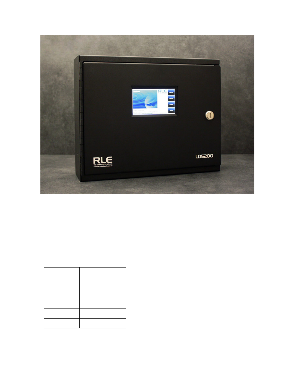
LD5200
User Guide
Version 2.3
Firmware Version 2.2.1
Page 2
Copyright and Trademark Notices
© Raymond & Lae Engineering, Inc. 2012. All rights reserved. RLE® is a registered trademark and
SeaHawk™, Falcon™, and Raptor™ are trademarks of Raymond & Lae Engineering, Inc. The
products sold by Raymond & Lae Engineering, Inc. are subject to the limited warranty, limited liability,
and other terms and conditions of sale set forth at http://rletech.com/assets/tc1-2.pdf.
Revision History
Rev. No. Date
1.0 April 2011
2.0 April 2012
2.1 May 2012
2.2 July 2013
2.3 April 2014
2 LD5200 User Guide 800.518.1519
Page 3

Product Registration
Product registration helps RLE Technologies inform owners of:
• Product upgrades
• Firmware enhancements
• New products and technologies
• Special offers available only to registered users
Submit registration information rletech.com.
Any information provided to RLE Technologies through the registration form will be regarded as
confidential. RLE will not sell or distribute any of the information to third parties.
Technical Support
Personal assistance is available Monday through Friday, from 8:00 a.m. to 5:00 p.m. MST.
A request for assistance may be sent to support@rletech.com
Otherwise, please call us directly at: 800.518.1519, and press “2” for technical support.
The following information is located on the bottom of each LD5200 unit. Please have this information
available whenever a technical support call is placed:
Product Model Number
Product Serial Number
Product Manufacture Date
rletech.com LD5200 User Guide 3
Page 4

RLE Product Warranty
Seller warrants to the Ultimate Purchaser (the purchaser who buys for use and not for resale) that all
products furnished under this order and which are manufactured by Seller will conform to final
specifications, drawings, samples and other written descriptions approved in writing by Seller, and will be
free from defects in materials and workmanship. These warranties shall remain in effect for a period of
twelve (12) months after shipment. If the Seller installs the equipment or supplies technical direction of
installation by contract, said one year shall run from the completion of installation, provided installation is not
unreasonably delayed by Ultimate Purchaser. Parts replaced or repaired in the warranty period shall carry
the unexpired portion of the original warranty. A unit placed with the purchaser on consignment and then
later purchased will be warranted for twelve (12) months from the time the Seller receives notification of the
Purchaser's intent to purchase said consigned item. The foregoing is in its entirety is subject to the provision
that in no case will the total warranty period extend beyond 18 months from date Seller ships equipment
from point of manufacture.
Products are NOT life and safety certified. In no event shall the Seller be liable for loss, damage, or expense
directly or indirectly arising from the use of the units, or from any other cause, except as expressly stated in
this warranty. Seller makes no warranties, express or implied, including any warranty as to merchantability
or fitness for a particular purpose or use. Seller is not liable for and Purchaser waives any right of action it
has or may have against Seller for any consequential or special damages arising out of any breach of
warranty, and for any damages Purchaser may claim for damage to any property or injury or death to any
person arising out of its purchase or the use, operation, or maintenance of the product. Seller will not be
liable for any labor subcontracted or performed by Purchaser for preparation of warranted item for return to
Seller's factory or for preparation work for field repair or replacement. Invoicing of Seller for labor either
performed or subcontracted by Purchaser will not be considered as a liability by the Seller.
The liability of Seller hereunder is limited to replacing or repairing at Seller's factory or on the job site at
Seller's option, any part or parts which have been returned to the Seller and which are defective or do not
conform to such specifications, drawings or other written descriptions; provided that such part or parts are
returned by the Ultimate Purchaser within ninety (90) days after such defect is discovered. The Seller shall
have the sole right to determine if the parts are to be repaired at the job site or whether they are to be
returned to the factory for repair or replacement. All items returned to Seller for repair or replacement must
be sent freight, prepaid to its factory. Purchaser must obtain Seller's Return Goods Authorization prior to
returning items. The above conditions must be met if warranty is to be valid. Seller will not be liable for any
damage done by unauthorized repair work, unauthorized replacement parts, from any misapplication of the
item, or for damage due to accident, abuse, or act of God.
This warranty shall be exclusive of any and all other warranties express or implied and may be modified only
by writing signed by any officer of the Seller. This warranty shall extend to the Ultimate Purchaser but to no
one else. Accessories supplied by Seller but manufactured by others carry any warranty the manufacturers
have made to Seller and which can be passed on to the Ultimate Purchaser.
Seller makes no warranty with respect to whether the products sold hereunder infringe any patent, U.S. or
foreign, and Purchaser represents that any specially ordered products do not infringe any patent. Purchaser
agrees to indemnify and hold Seller harmless from any liability by virtue of any patent claims where
Purchaser has ordered a product conforming to Purchaser's specifications, or conforming to Purchaser's
specific design.
Purchaser has not relied and shall not rely on any oral representation regarding the Product sold hereunder
and any oral representation shall not bind Seller and shall not be part of any warranty.
4 LD5200 User Guide 800.518.1519
Page 5

Contents
1 Product Overview . . . . . . . . . . . . . . . . . . . . . . . . . . . . . . . . . . . . . . . . . . . . . . . . . . . 13
Description . . . . . . . . . . . . . . . . . . . . . . . . . . . . . . . . . . . . . . . . . . . . . . . . . . . . . . . . . . . . . . . . . . . . . . 13
Operation . . . . . . . . . . . . . . . . . . . . . . . . . . . . . . . . . . . . . . . . . . . . . . . . . . . . . . . . . . . . . . . . . . . . . . . 13
Supervised System . . . . . . . . . . . . . . . . . . . . . . . . . . . . . . . . . . . . . . . . . . . . . . . . . . . . . . . . . . . 13
Distance-Read Leak Detection . . . . . . . . . . . . . . . . . . . . . . . . . . . . . . . . . . . . . . . . . . . . . . . . . . 14
User Configuration and Communication . . . . . . . . . . . . . . . . . . . . . . . . . . . . . . . . . . . . . . . . . . . 14
2 Installation . . . . . . . . . . . . . . . . . . . . . . . . . . . . . . . . . . . . . . . . . . . . . . . . . . . . . . . . .15
Prepare for Installation . . . . . . . . . . . . . . . . . . . . . . . . . . . . . . . . . . . . . . . . . . . . . . . . . . . . . . . . . . . . . 15
Mount the LD5200. . . . . . . . . . . . . . . . . . . . . . . . . . . . . . . . . . . . . . . . . . . . . . . . . . . . . . . . . . . . . . . . . 16
Establish Physical Connections . . . . . . . . . . . . . . . . . . . . . . . . . . . . . . . . . . . . . . . . . . . . . . . . . . . . . . 16
TB1: 4-20mA Output . . . . . . . . . . . . . . . . . . . . . . . . . . . . . . . . . . . . . . . . . . . . . . . . . . . . . . . . . . 18
TB2: Sensing Cable Interface . . . . . . . . . . . . . . . . . . . . . . . . . . . . . . . . . . . . . . . . . . . . . . . . . . . 18
TB3: Maintenance Relay . . . . . . . . . . . . . . . . . . . . . . . . . . . . . . . . . . . . . . . . . . . . . . . . . . . . . . . 18
TB4: Two Fault/Leak Relay Outputs . . . . . . . . . . . . . . . . . . . . . . . . . . . . . . . . . . . . . . . . . . . . . . 18
P1: EIA-232 Connector . . . . . . . . . . . . . . . . . . . . . . . . . . . . . . . . . . . . . . . . . . . . . . . . . . . . . . . . 19
SW1: TB5 Port 3 Termination Switch. . . . . . . . . . . . . . . . . . . . . . . . . . . . . . . . . . . . . . . . . . . . . . 19
TB5 and TB6: EIA-485 Modbus Ports . . . . . . . . . . . . . . . . . . . . . . . . . . . . . . . . . . . . . . . . . . . . . 19
SW2: TB6 Port 2 (Bottom Row) Termination Switch . . . . . . . . . . . . . . . . . . . . . . . . . . . . . . . . . . 20
SW3: TB6 Port 1 (Top Row) Termination Switch. . . . . . . . . . . . . . . . . . . . . . . . . . . . . . . . . . . . . 20
P2: RJ45 Network . . . . . . . . . . . . . . . . . . . . . . . . . . . . . . . . . . . . . . . . . . . . . . . . . . . . . . . . . . . . 20
P3: Optional Power Connection . . . . . . . . . . . . . . . . . . . . . . . . . . . . . . . . . . . . . . . . . . . . . . . . . . 20
TB7: Input Power (from Input AC Power Supply). . . . . . . . . . . . . . . . . . . . . . . . . . . . . . . . . . . . . 20
DS1: Status LED . . . . . . . . . . . . . . . . . . . . . . . . . . . . . . . . . . . . . . . . . . . . . . . . . . . . . . . . . . . . . 20
Connect the SeaHawk Sensing Cable . . . . . . . . . . . . . . . . . . . . . . . . . . . . . . . . . . . . . . . . . . . . . . . . . 21
Connect Lengths of Sensing Cable . . . . . . . . . . . . . . . . . . . . . . . . . . . . . . . . . . . . . . . . . . . . . . . 21
Secure Sensing Cable to the Floor . . . . . . . . . . . . . . . . . . . . . . . . . . . . . . . . . . . . . . . . . . . . . . . 21
Apply Power to the LD5200 . . . . . . . . . . . . . . . . . . . . . . . . . . . . . . . . . . . . . . . . . . . . . . . . . . . . . . . . . 22
Configure Communications. . . . . . . . . . . . . . . . . . . . . . . . . . . . . . . . . . . . . . . . . . . . . . . . . . . . . . . . . . 23
Access the Configuration Menu . . . . . . . . . . . . . . . . . . . . . . . . . . . . . . . . . . . . . . . . . . . . . . . . . . 23
Test the System . . . . . . . . . . . . . . . . . . . . . . . . . . . . . . . . . . . . . . . . . . . . . . . . . . . . . . . . . . . . . . . . . . 24
Calibrate Cable Resistance. . . . . . . . . . . . . . . . . . . . . . . . . . . . . . . . . . . . . . . . . . . . . . . . . . . . . . . . . . 25
Configure Security Settings. . . . . . . . . . . . . . . . . . . . . . . . . . . . . . . . . . . . . . . . . . . . . . . . . . . . . . . . . . 27
General Operation. . . . . . . . . . . . . . . . . . . . . . . . . . . . . . . . . . . . . . . . . . . . . . . . . . . . . . . . . . . . . . . . . 27
3 LCD Touch Screen Interface . . . . . . . . . . . . . . . . . . . . . . . . . . . . . . . . . . . . . . . . . . 29
Main Menu . . . . . . . . . . . . . . . . . . . . . . . . . . . . . . . . . . . . . . . . . . . . . . . . . . . . . . . . . . . . . . . . . . . . . . 30
Silence Button . . . . . . . . . . . . . . . . . . . . . . . . . . . . . . . . . . . . . . . . . . . . . . . . . . . . . . . . . . . . . . . . . . . . 30
Alarms Button . . . . . . . . . . . . . . . . . . . . . . . . . . . . . . . . . . . . . . . . . . . . . . . . . . . . . . . . . . . . . . . . . . . . 31
History . . . . . . . . . . . . . . . . . . . . . . . . . . . . . . . . . . . . . . . . . . . . . . . . . . . . . . . . . . . . . . . . . . . . . 32
Status Button. . . . . . . . . . . . . . . . . . . . . . . . . . . . . . . . . . . . . . . . . . . . . . . . . . . . . . . . . . . . . . . . . . . . . 33
System Button . . . . . . . . . . . . . . . . . . . . . . . . . . . . . . . . . . . . . . . . . . . . . . . . . . . . . . . . . . . . . . . 35
Setup Button . . . . . . . . . . . . . . . . . . . . . . . . . . . . . . . . . . . . . . . . . . . . . . . . . . . . . . . . . . . . . . . . . . . . . 36
Leak Settings . . . . . . . . . . . . . . . . . . . . . . . . . . . . . . . . . . . . . . . . . . . . . . . . . . . . . . . . . . . . . . . . 37
Virtual Zone . . . . . . . . . . . . . . . . . . . . . . . . . . . . . . . . . . . . . . . . . . . . . . . . . . . . . . . . . . . . . . . . . 40
Slave Zone . . . . . . . . . . . . . . . . . . . . . . . . . . . . . . . . . . . . . . . . . . . . . . . . . . . . . . . . . . . . . . . . . . 41
4-20mA Output. . . . . . . . . . . . . . . . . . . . . . . . . . . . . . . . . . . . . . . . . . . . . . . . . . . . . . . . . . . . . . . 42
rletech.com LD5200 User Guide 5
Page 6

Preventative Maintenance . . . . . . . . . . . . . . . . . . . . . . . . . . . . . . . . . . . . . . . . . . . . . . . . . . . . . . 43
System Settings . . . . . . . . . . . . . . . . . . . . . . . . . . . . . . . . . . . . . . . . . . . . . . . . . . . . . . . . . . . . . . 44
EIA-485 / Modbus / N2 . . . . . . . . . . . . . . . . . . . . . . . . . . . . . . . . . . . . . . . . . . . . . . . . . . . . . . . . . 45
Bacnet . . . . . . . . . . . . . . . . . . . . . . . . . . . . . . . . . . . . . . . . . . . . . . . . . . . . . . . . . . . . . . . . . . . . . 46
Clear History. . . . . . . . . . . . . . . . . . . . . . . . . . . . . . . . . . . . . . . . . . . . . . . . . . . . . . . . . . . . . . . . . 46
4 Web Interface . . . . . . . . . . . . . . . . . . . . . . . . . . . . . . . . . . . . . . . . . . . . . . . . . . . . . . 47
Home Page . . . . . . . . . . . . . . . . . . . . . . . . . . . . . . . . . . . . . . . . . . . . . . . . . . . . . . . . . . . . . . . . . . . . . . 47
Identity . . . . . . . . . . . . . . . . . . . . . . . . . . . . . . . . . . . . . . . . . . . . . . . . . . . . . . . . . . . . . . . . . . . . . . . . . . 48
Configuration . . . . . . . . . . . . . . . . . . . . . . . . . . . . . . . . . . . . . . . . . . . . . . . . . . . . . . . . . . . . . . . . . . . . . 49
Leak . . . . . . . . . . . . . . . . . . . . . . . . . . . . . . . . . . . . . . . . . . . . . . . . . . . . . . . . . . . . . . . . . . . . . . . 50
Virtual Zone . . . . . . . . . . . . . . . . . . . . . . . . . . . . . . . . . . . . . . . . . . . . . . . . . . . . . . . . . . . . . . . . . 54
Slave Controller . . . . . . . . . . . . . . . . . . . . . . . . . . . . . . . . . . . . . . . . . . . . . . . . . . . . . . . . . . . . . . 55
Slave Zones . . . . . . . . . . . . . . . . . . . . . . . . . . . . . . . . . . . . . . . . . . . . . . . . . . . . . . . . . . . . . . . . . 56
Network/IP . . . . . . . . . . . . . . . . . . . . . . . . . . . . . . . . . . . . . . . . . . . . . . . . . . . . . . . . . . . . . . . . . . 57
Network Statistics . . . . . . . . . . . . . . . . . . . . . . . . . . . . . . . . . . . . . . . . . . . . . . . . . . . . . . . . . . . . . 58
Web . . . . . . . . . . . . . . . . . . . . . . . . . . . . . . . . . . . . . . . . . . . . . . . . . . . . . . . . . . . . . . . . . . . . . . . 59
Map. . . . . . . . . . . . . . . . . . . . . . . . . . . . . . . . . . . . . . . . . . . . . . . . . . . . . . . . . . . . . . . . . . . . . . . . 60
Upload the Map Image. . . . . . . . . . . . . . . . . . . . . . . . . . . . . . . . . . . . . . . . . . . . . . . . . . . . . . 63
Map Reference Points . . . . . . . . . . . . . . . . . . . . . . . . . . . . . . . . . . . . . . . . . . . . . . . . . . . . . . 64
Test the Mapped Coordinates . . . . . . . . . . . . . . . . . . . . . . . . . . . . . . . . . . . . . . . . . . . . . . . . 66
Viewing the Map. . . . . . . . . . . . . . . . . . . . . . . . . . . . . . . . . . . . . . . . . . . . . . . . . . . . . . . . . . . 69
Clock. . . . . . . . . . . . . . . . . . . . . . . . . . . . . . . . . . . . . . . . . . . . . . . . . . . . . . . . . . . . . . . . . . . . . . . 69
NTP . . . . . . . . . . . . . . . . . . . . . . . . . . . . . . . . . . . . . . . . . . . . . . . . . . . . . . . . . . . . . . . . . . . . . . . 70
Email-SMTP/DNS. . . . . . . . . . . . . . . . . . . . . . . . . . . . . . . . . . . . . . . . . . . . . . . . . . . . . . . . . . . . . 72
SNMP/Syslog . . . . . . . . . . . . . . . . . . . . . . . . . . . . . . . . . . . . . . . . . . . . . . . . . . . . . . . . . . . . . . . . 74
EIA-485 Port/Modbus/N2 . . . . . . . . . . . . . . . . . . . . . . . . . . . . . . . . . . . . . . . . . . . . . . . . . . . . . . . 76
Bacnet . . . . . . . . . . . . . . . . . . . . . . . . . . . . . . . . . . . . . . . . . . . . . . . . . . . . . . . . . . . . . . . . . . . . . 78
Alarm Management . . . . . . . . . . . . . . . . . . . . . . . . . . . . . . . . . . . . . . . . . . . . . . . . . . . . . . . . . . . 80
System/Flash Management . . . . . . . . . . . . . . . . . . . . . . . . . . . . . . . . . . . . . . . . . . . . . . . . . . . . . 81
Product Registration . . . . . . . . . . . . . . . . . . . . . . . . . . . . . . . . . . . . . . . . . . . . . . . . . . . . . . . . . . . 81
Historical Data . . . . . . . . . . . . . . . . . . . . . . . . . . . . . . . . . . . . . . . . . . . . . . . . . . . . . . . . . . . . . . . . . . . . 82
Refresh . . . . . . . . . . . . . . . . . . . . . . . . . . . . . . . . . . . . . . . . . . . . . . . . . . . . . . . . . . . . . . . . . . . . . . . . . 84
5 Modbus Communication . . . . . . . . . . . . . . . . . . . . . . . . . . . . . . . . . . . . . . . . . . . . . 85
Comm Port Settings. . . . . . . . . . . . . . . . . . . . . . . . . . . . . . . . . . . . . . . . . . . . . . . . . . . . . . . . . . . . . . . . 85
Leak Detection Modbus Master . . . . . . . . . . . . . . . . . . . . . . . . . . . . . . . . . . . . . . . . . . . . . . . . . . . . . . . 85
Connect Distance Read Panels to the LD5200 . . . . . . . . . . . . . . . . . . . . . . . . . . . . . . . . . . . . . . 85
Implementation Basics. . . . . . . . . . . . . . . . . . . . . . . . . . . . . . . . . . . . . . . . . . . . . . . . . . . . . . . . . . . . . . 86
Modes of Transmission . . . . . . . . . . . . . . . . . . . . . . . . . . . . . . . . . . . . . . . . . . . . . . . . . . . . . . . . 86
Slave Address Field . . . . . . . . . . . . . . . . . . . . . . . . . . . . . . . . . . . . . . . . . . . . . . . . . . . . . . . . 86
Function Field. . . . . . . . . . . . . . . . . . . . . . . . . . . . . . . . . . . . . . . . . . . . . . . . . . . . . . . . . . . . . 86
Data Field. . . . . . . . . . . . . . . . . . . . . . . . . . . . . . . . . . . . . . . . . . . . . . . . . . . . . . . . . . . . . . . . 86
Error Check (Checksum) Field. . . . . . . . . . . . . . . . . . . . . . . . . . . . . . . . . . . . . . . . . . . . . . . . 87
Packet Communications For The LD5200. . . . . . . . . . . . . . . . . . . . . . . . . . . . . . . . . . . . . . . . . . . . . . . 87
Function 03: Read Output Registers . . . . . . . . . . . . . . . . . . . . . . . . . . . . . . . . . . . . . . . . . . . . . . 87
Function 04: Read Input Registers . . . . . . . . . . . . . . . . . . . . . . . . . . . . . . . . . . . . . . . . . . . . . . . . 89
Function 06: Preset Single Register . . . . . . . . . . . . . . . . . . . . . . . . . . . . . . . . . . . . . . . . . . . . . . . 99
Function 16: Preset Multiple Registers . . . . . . . . . . . . . . . . . . . . . . . . . . . . . . . . . . . . . . . . . . . . . 99
RTU Framing . . . . . . . . . . . . . . . . . . . . . . . . . . . . . . . . . . . . . . . . . . . . . . . . . . . . . . . . . . . . . . . . . . . . 100
A Update Firmware . . . . . . . . . . . . . . . . . . . . . . . . . . . . . . . . . . . . . . . . . . . . . . . . . . 101
Update the LD5200 Firmware . . . . . . . . . . . . . . . . . . . . . . . . . . . . . . . . . . . . . . . . . . . . . . . . . . . . . . . 101
B EIA-232 Interface . . . . . . . . . . . . . . . . . . . . . . . . . . . . . . . . . . . . . . . . . . . . . . . . . . 103
Set the IP Address through the EIA-232 Port . . . . . . . . . . . . . . . . . . . . . . . . . . . . . . . . . . . . . . . . . . . 103
Boot Up . . . . . . . . . . . . . . . . . . . . . . . . . . . . . . . . . . . . . . . . . . . . . . . . . . . . . . . . . . . . . . . . . . . . . . . . 104
6 LD5200 User Guide 800.518.1519
Page 7

Main Menu . . . . . . . . . . . . . . . . . . . . . . . . . . . . . . . . . . . . . . . . . . . . . . . . . . . . . . . . . . . . . . . . . . . . . 104
Other Main Menu Functions . . . . . . . . . . . . . . . . . . . . . . . . . . . . . . . . . . . . . . . . . . . . . . . . . . . . . . . . 105
C Preventive Maintenance . . . . . . . . . . . . . . . . . . . . . . . . . . . . . . . . . . . . . . . . . . . . .107
D Troubleshooting . . . . . . . . . . . . . . . . . . . . . . . . . . . . . . . . . . . . . . . . . . . . . . . . . . . 109
Troubleshooting Problems with the LD5200 . . . . . . . . . . . . . . . . . . . . . . . . . . . . . . . . . . . . . . . . . . . . 109
Troubleshooting Sensing Cable . . . . . . . . . . . . . . . . . . . . . . . . . . . . . . . . . . . . . . . . . . . . . . . . . . . . . 112
E 4-20mA Output Testing. . . . . . . . . . . . . . . . . . . . . . . . . . . . . . . . . . . . . . . . . . . . . . 115
F Technical Specifications . . . . . . . . . . . . . . . . . . . . . . . . . . . . . . . . . . . . . . . . . . . . 117
rletech.com LD5200 User Guide 7
Page 8

8 LD5200 User Guide 800.518.1519
Page 9

Figures
1 Product Overview . . . . . . . . . . . . . . . . . . . . . . . . . . . . . . . . . . . . . . . . . . . . . . . . . . . 13
2 Installation . . . . . . . . . . . . . . . . . . . . . . . . . . . . . . . . . . . . . . . . . . . . . . . . . . . . . . . .15
Figure 2.1 LD5200 Wall Mounting Kit. . . . . . . . . . . . . . . . . . . . . . . . . . . . . . . . . . . . . . . . . 16
Figure 2.2 LD5200 Physical Connections and Switches . . . . . . . . . . . . . . . . . . . . . . . . . . 17
Figure 2.3 Cable Connection TB2 . . . . . . . . . . . . . . . . . . . . . . . . . . . . . . . . . . . . . . . . . . . 18
Figure 2.4 SeaHawk Sensing Cable . . . . . . . . . . . . . . . . . . . . . . . . . . . . . . . . . . . . . . . . . 21
Figure 2.5 Secure the Cable . . . . . . . . . . . . . . . . . . . . . . . . . . . . . . . . . . . . . . . . . . . . . . . 22
Figure 2.6 Apply Moisture to the Cable for Testing Purposes . . . . . . . . . . . . . . . . . . . . . . 24
3 LCD Touch Screen Interface . . . . . . . . . . . . . . . . . . . . . . . . . . . . . . . . . . . . . . . . . . 29
4 Web Interface . . . . . . . . . . . . . . . . . . . . . . . . . . . . . . . . . . . . . . . . . . . . . . . . . . . . . . 47
Figure 4.1 LD5200 Web Interface Home Page . . . . . . . . . . . . . . . . . . . . . . . . . . . . . . . . . 47
Figure 4.2 LD5200 Web Interface Home Page with Active Leak Detected Alarm . . . . . . . 48
Figure 4.3 Identity Page . . . . . . . . . . . . . . . . . . . . . . . . . . . . . . . . . . . . . . . . . . . . . . . . . . . 48
Figure 4.4 Configuration Page . . . . . . . . . . . . . . . . . . . . . . . . . . . . . . . . . . . . . . . . . . . . . . 49
Figure 4.5 Leak Configuration Page. . . . . . . . . . . . . . . . . . . . . . . . . . . . . . . . . . . . . . . . . . 50
Figure 4.6 Virtual Zone Configuration Page . . . . . . . . . . . . . . . . . . . . . . . . . . . . . . . . . . . . 54
Figure 4.7 Slave Controller Configuration Page. . . . . . . . . . . . . . . . . . . . . . . . . . . . . . . . . 55
Figure 4.8 Slave Zone Configuration Page, Distance-Read via Modbus . . . . . . . . . . . . . . 56
Figure 4.9 Slave Zone Configuration Page, Zone . . . . . . . . . . . . . . . . . . . . . . . . . . . . . . . 56
Figure 4.10 Network/IP Configuration Page. . . . . . . . . . . . . . . . . . . . . . . . . . . . . . . . . . . . . 57
Figure 4.11 Network Statistics Page . . . . . . . . . . . . . . . . . . . . . . . . . . . . . . . . . . . . . . . . . . 58
Figure 4.12 Web Configuration Page . . . . . . . . . . . . . . . . . . . . . . . . . . . . . . . . . . . . . . . . . . 59
Figure 4.13 Leak Detection Reference Map. . . . . . . . . . . . . . . . . . . . . . . . . . . . . . . . . . . . . 60
Figure 4.14 Map Settings Page . . . . . . . . . . . . . . . . . . . . . . . . . . . . . . . . . . . . . . . . . . . . . . 61
Figure 4.15 Map Configuration Page . . . . . . . . . . . . . . . . . . . . . . . . . . . . . . . . . . . . . . . . . . 64
Figure 4.16 Map Image Upload Message . . . . . . . . . . . . . . . . . . . . . . . . . . . . . . . . . . . . . . 64
Figure 4.17 Map Image Upload Error Message . . . . . . . . . . . . . . . . . . . . . . . . . . . . . . . . . . 64
Figure 4.18 Mapping Crosshairs - Reference Point . . . . . . . . . . . . . . . . . . . . . . . . . . . . . . . 65
Figure 4.19 Map Key . . . . . . . . . . . . . . . . . . . . . . . . . . . . . . . . . . . . . . . . . . . . . . . . . . . . . . 65
Figure 4.20 Graphical Mapping Link . . . . . . . . . . . . . . . . . . . . . . . . . . . . . . . . . . . . . . . . . . 65
Figure 4.21 Mark the Beginning of the Cable Run . . . . . . . . . . . . . . . . . . . . . . . . . . . . . . . . 66
Figure 4.22 Crosshairs Designate the Mapped Coordinate . . . . . . . . . . . . . . . . . . . . . . . . . 66
Figure 4.23 Coordinates Have Been Mapped - Return to the Map Configuration Page . . . 66
Figure 4.24 Click the Map Alarm Test Link to View All Mapped Points in an Alarm State . . 67
Figure 4.25 Map (Image) Buttons on Home Page . . . . . . . . . . . . . . . . . . . . . . . . . . . . . . . . 69
Figure 4.26 Clock Configuration Page . . . . . . . . . . . . . . . . . . . . . . . . . . . . . . . . . . . . . . . . . 69
Figure 4.27 NTP Configuration Page . . . . . . . . . . . . . . . . . . . . . . . . . . . . . . . . . . . . . . . . . . 70
Figure 4.28 Email-SMTP/DNS Configuration Page . . . . . . . . . . . . . . . . . . . . . . . . . . . . . . . 72
Figure 4.29 SNMP/Syslog Page. . . . . . . . . . . . . . . . . . . . . . . . . . . . . . . . . . . . . . . . . . . . . . 74
Figure 4.30 Modbus EIA-485 Page . . . . . . . . . . . . . . . . . . . . . . . . . . . . . . . . . . . . . . . . . . . 76
Figure 4.31 Bacnet Page . . . . . . . . . . . . . . . . . . . . . . . . . . . . . . . . . . . . . . . . . . . . . . . . . . . 79
rletech.com LD5200 User Guide 9
Page 10

Figure 4.32 Alarm Management Page . . . . . . . . . . . . . . . . . . . . . . . . . . . . . . . . . . . . . . . . . 80
Figure 4.33 System/Flash Management Page . . . . . . . . . . . . . . . . . . . . . . . . . . . . . . . . . . . 81
Figure 4.34 Historical Data Page . . . . . . . . . . . . . . . . . . . . . . . . . . . . . . . . . . . . . . . . . . . . . 82
Figure 4.35 Alarm History Text File (.txt) . . . . . . . . . . . . . . . . . . . . . . . . . . . . . . . . . . . . . . . 83
Figure 4.36 Trend Log . . . . . . . . . . . . . . . . . . . . . . . . . . . . . . . . . . . . . . . . . . . . . . . . . . . . . 84
5 Modbus Communication . . . . . . . . . . . . . . . . . . . . . . . . . . . . . . . . . . . . . . . . . . . . . 85
Figure 5.1 LD5200 Connection Diagram . . . . . . . . . . . . . . . . . . . . . . . . . . . . . . . . . . . . . . . 86
A Update Firmware . . . . . . . . . . . . . . . . . . . . . . . . . . . . . . . . . . . . . . . . . . . . . . . . . . 101
Figure A.1 System/Flash Management Page. . . . . . . . . . . . . . . . . . . . . . . . . . . . . . . . . . 101
Figure A.2 Choose the Firmware File. . . . . . . . . . . . . . . . . . . . . . . . . . . . . . . . . . . . . . . . 102
Figure A.3 Firmware Load Message. . . . . . . . . . . . . . . . . . . . . . . . . . . . . . . . . . . . . . . . . 102
B EIA-232 Interface . . . . . . . . . . . . . . . . . . . . . . . . . . . . . . . . . . . . . . . . . . . . . . . . . . 103
Figure B.1 EIA-232 Main Menu Screen . . . . . . . . . . . . . . . . . . . . . . . . . . . . . . . . . . . . . . 104
C Preventive Maintenance . . . . . . . . . . . . . . . . . . . . . . . . . . . . . . . . . . . . . . . . . . . . 107
D Troubleshooting . . . . . . . . . . . . . . . . . . . . . . . . . . . . . . . . . . . . . . . . . . . . . . . . . . 109
E 4-20mA Output Testing . . . . . . . . . . . . . . . . . . . . . . . . . . . . . . . . . . . . . . . . . . . . . 115
Figure E.1 4-20mA Testing. . . . . . . . . . . . . . . . . . . . . . . . . . . . . . . . . . . . . . . . . . . . . . . . 115
F Technical Specifications . . . . . . . . . . . . . . . . . . . . . . . . . . . . . . . . . . . . . . . . . . . . 117
10 LD5200 User Guide 800.518.1519
Page 11

Tables
1 Product Overview . . . . . . . . . . . . . . . . . . . . . . . . . . . . . . . . . . . . . . . . . . . . . . . . . . 13
2 Installation . . . . . . . . . . . . . . . . . . . . . . . . . . . . . . . . . . . . . . . . . . . . . . . . . . . . . . . . 15
3 LCD Touch Screen Interface . . . . . . . . . . . . . . . . . . . . . . . . . . . . . . . . . . . . . . . . . 29
Table 3.1 LCD - Main Buttons. . . . . . . . . . . . . . . . . . . . . . . . . . . . . . . . . . . . . . . . . . . . . . 29
Table 3.2 LCD Main Menu Buttons . . . . . . . . . . . . . . . . . . . . . . . . . . . . . . . . . . . . . . . . . . 30
Table 3.3 LCD Current Alarm Color Codes. . . . . . . . . . . . . . . . . . . . . . . . . . . . . . . . . . . . 31
Table 3.4 LCD Current Alarm Buttons. . . . . . . . . . . . . . . . . . . . . . . . . . . . . . . . . . . . . . . . 31
Table 3.5 LCD Alarm History Color Codes . . . . . . . . . . . . . . . . . . . . . . . . . . . . . . . . . . . . 32
Table 3.6 LCD Alarm History Buttons . . . . . . . . . . . . . . . . . . . . . . . . . . . . . . . . . . . . . . . . 32
Table 3.7 LCD Controller Status Information Fields . . . . . . . . . . . . . . . . . . . . . . . . . . . . . 33
Table 3.8 LCD Controller Status Buttons . . . . . . . . . . . . . . . . . . . . . . . . . . . . . . . . . . . . . 34
Table 3.9 LCD System Status Button Options . . . . . . . . . . . . . . . . . . . . . . . . . . . . . . . . . 35
Table 3.10 LCD Leak Settings - Configurable Options . . . . . . . . . . . . . . . . . . . . . . . . . . . . 37
Table 3.11 LCD Virtual Zone Settings - Configurable Options . . . . . . . . . . . . . . . . . . . . . . 40
Table 3.12 LCD Slave Zones Setup - Configurable Options. . . . . . . . . . . . . . . . . . . . . . . . 41
Table 3.13 LCD 4-20mA Settings - Configurable Options. . . . . . . . . . . . . . . . . . . . . . . . . . 42
Table 3.14 LCD Preventative Maintenance - Configurable Options . . . . . . . . . . . . . . . . . . 43
Table 3.15 LCD System Settings - Configurable Options . . . . . . . . . . . . . . . . . . . . . . . . . . 44
Table 3.16 LCD EIA-485 / Modbus / N2 Setup - Configurable Options . . . . . . . . . . . . . . . 45
Table 3.17 LCD Bacnet Setup - Configurable Options . . . . . . . . . . . . . . . . . . . . . . . . . . . . 46
4 Web Interface. . . . . . . . . . . . . . . . . . . . . . . . . . . . . . . . . . . . . . . . . . . . . . . . . . . . . . 47
Table 4.1 Leak Configuration Options. . . . . . . . . . . . . . . . . . . . . . . . . . . . . . . . . . . . . . . . 51
Table 4.2 Virtual Zone Configuration Options . . . . . . . . . . . . . . . . . . . . . . . . . . . . . . . . . . 54
Table 4.3 Slave Controller Configuration Options. . . . . . . . . . . . . . . . . . . . . . . . . . . . . . . 55
Table 4.4 LDZ/Slave Zone Label Configuration Options. . . . . . . . . . . . . . . . . . . . . . . . . . 56
Table 4.5 Network/IP Configuration Options. . . . . . . . . . . . . . . . . . . . . . . . . . . . . . . . . . . 57
Table 4.6 Web Configuration Options . . . . . . . . . . . . . . . . . . . . . . . . . . . . . . . . . . . . . . . . 59
Table 4.7 Map Settings Options . . . . . . . . . . . . . . . . . . . . . . . . . . . . . . . . . . . . . . . . . . . . 61
Table 4.8 Clock Configuration Options . . . . . . . . . . . . . . . . . . . . . . . . . . . . . . . . . . . . . . . 69
Table 4.9 NTP Configuration Options . . . . . . . . . . . . . . . . . . . . . . . . . . . . . . . . . . . . . . . . 70
Table 4.10 Email-SMTP/DNS Configuration Options . . . . . . . . . . . . . . . . . . . . . . . . . . . . . 72
Table 4.11 SNMP/Syslog Options. . . . . . . . . . . . . . . . . . . . . . . . . . . . . . . . . . . . . . . . . . . . 74
Table 4.12 Modbus/EIA-485 Options . . . . . . . . . . . . . . . . . . . . . . . . . . . . . . . . . . . . . . . . . 76
Table 4.13 Bacnet Options . . . . . . . . . . . . . . . . . . . . . . . . . . . . . . . . . . . . . . . . . . . . . . . . . 79
Table 4.14 Alarm Management Options . . . . . . . . . . . . . . . . . . . . . . . . . . . . . . . . . . . . . . . 80
Table 4.15 System/Flash Management Options . . . . . . . . . . . . . . . . . . . . . . . . . . . . . . . . . 81
Table 4.16 Historical Data Options . . . . . . . . . . . . . . . . . . . . . . . . . . . . . . . . . . . . . . . . . . . 82
Table 4.17 Alarm History Log Description. . . . . . . . . . . . . . . . . . . . . . . . . . . . . . . . . . . . . . 83
5 Modbus Communication . . . . . . . . . . . . . . . . . . . . . . . . . . . . . . . . . . . . . . . . . . . . 85
Table 5.1 Exception Codes . . . . . . . . . . . . . . . . . . . . . . . . . . . . . . . . . . . . . . . . . . . . . . . . 87
rletech.com LD5200 User Guide 11
Page 12

Table 5.2 Read Output Registers Packet Structure . . . . . . . . . . . . . . . . . . . . . . . . . . . . . 87
Table 5.3 Output Registers . . . . . . . . . . . . . . . . . . . . . . . . . . . . . . . . . . . . . . . . . . . . . . . . 88
Table 5.4 Read Input Registers Packet Structure. . . . . . . . . . . . . . . . . . . . . . . . . . . . . . . 89
Table 5.5 Input Registers . . . . . . . . . . . . . . . . . . . . . . . . . . . . . . . . . . . . . . . . . . . . . . . . . 90
Table 5.6 Status Flags (Registers 30010 and 30011). . . . . . . . . . . . . . . . . . . . . . . . . . . . 98
Table 5.7 Status Flags (Register 30013 - 30273) . . . . . . . . . . . . . . . . . . . . . . . . . . . . . . . 98
Table 5.8 Preset Single Register Packet Structure. . . . . . . . . . . . . . . . . . . . . . . . . . . . . . 99
Table 5.9 Preset Multiple Registers Packet Structure. . . . . . . . . . . . . . . . . . . . . . . . . . . . 99
Table 5.10 Query Sample . . . . . . . . . . . . . . . . . . . . . . . . . . . . . . . . . . . . . . . . . . . . . . . . . 100
Table 5.11 Response Sample. . . . . . . . . . . . . . . . . . . . . . . . . . . . . . . . . . . . . . . . . . . . . . 100
A Update Firmware . . . . . . . . . . . . . . . . . . . . . . . . . . . . . . . . . . . . . . . . . . . . . . . . . 101
B EIA-232 Interface . . . . . . . . . . . . . . . . . . . . . . . . . . . . . . . . . . . . . . . . . . . . . . . . . 103
Table B.1 Other Main Menu Functions . . . . . . . . . . . . . . . . . . . . . . . . . . . . . . . . . . . . . . 105
C Preventive Maintenance. . . . . . . . . . . . . . . . . . . . . . . . . . . . . . . . . . . . . . . . . . . . 107
D Troubleshooting . . . . . . . . . . . . . . . . . . . . . . . . . . . . . . . . . . . . . . . . . . . . . . . . . . 109
Table D.1 Troubleshoot Problems with the LD5200 . . . . . . . . . . . . . . . . . . . . . . . . . . . . 109
Table D.2 Troubleshoot Sensing Cable. . . . . . . . . . . . . . . . . . . . . . . . . . . . . . . . . . . . . . 112
E 4-20mA Output Testing . . . . . . . . . . . . . . . . . . . . . . . . . . . . . . . . . . . . . . . . . . . . 115
F Technical Specifications . . . . . . . . . . . . . . . . . . . . . . . . . . . . . . . . . . . . . . . . . . . 117
Table F.1 Technical Specifications . . . . . . . . . . . . . . . . . . . . . . . . . . . . . . . . . . . . . . . . . 117
12 LD5200 User Guide 800.518.1519
Page 13

1.1 Description
The LD5200 is a distance-read leak detection controller. It can operate as a stand-alone device
or connect to multiple RLE leak detection controllers through its Ethernet or EIA-485 ports.
When coupled with up to 10,000 feet (3084m) of RLE’s sensing cable, it reports the presence
of water and other conductive liquids. When a conductive liquid comes in contact with the
sensing cable, the following occurs:
C HAPTER
CHAPTER 0PRODUCT OVERVIEW
♦ An audible alarm sounds.
♦ The distance to the leak is shown on the LD5200’s LCD touch screen and on the LD5200’s
web interface. An integrated reference map within the web interface will also show the
location of the leak.
♦ Notification is sent via email or Modbus/SNMP/BACnet/SMTP to a central control
location, such as a building management system (BMS).
1.2 Operation
1.2.1 Supervised System
The LD5200 is a supervised system - it continually monitors sensing cable, spot detectors, and
connected leak detection controllers for continuity and produces alarms for the following
conditions:
♦ Leak detection
♦ Cable break
♦ Cable contamination
♦ Loss of communications
rletech.com LD5200 User Guide 13
Page 14

1 Product Overview
1.2.2 Distance-Read Leak Detection
When the LD5200’s circuitry measures a current in excess of the user-defined leak threshold,
the unit’s microprocessor computes the distance to the leak. The LD5200 then annunciates the
leak and logs the alarm in its event log. The leak is communicated via email/Modbus/SNMP/
BACnet/SMTP/4-20mA to an equipped monitoring system. The relay output sends
notification to an alarm panel or monitoring system.
1.2.3 User Configuration and Communication
All the functionality needed to operate the LD5200 as a stand-alone device is accessible from
the LCD touch screen. Virtual buttons line the right side of the screen. Press the button for the
task you want to perform, and the screen for that task is displayed. Avoid using a pen or other
sharp object to activate the buttons on the LCD. This will damage the display.
The web-based user interface provides more extensive configuration options and allows users
to create an interactive map - a graphical representation of the monitored environment and
leak detection equipment. This web interface can be used on site or remotely via network
communications.
Digital fault and leak relay outputs and a 4-20mA relay output and allow the LD5200 to
interface with third-party management systems. The LD5200 also provides Modbus outputs
via EIA-485, twisted-pair wire, or TCP/IP, as well as BACnet/IP or BACnet/MSTP, SNMP,
and SMTP outputs.
14 LD5200 User Guide 800.518.1519
Page 15

2.1 Prepare for Installation
To install the LD5200, you’ll need the following supplies:
Included with the LD5200
C HAPTER
CHAPTER 0INSTALLATION
♦ Wall mount kit
♦ Cross-over cable (blue with yellow ends)
♦ 15 foot (4.57m) leader cable
♦ End-of-line terminator (EOL)
Available from RLE, sold separately
♦ SeaHawk Sensing Cable, up to 10,000 feet (3048m) of cable with a resistance of 2.800
ohms per foot, or up to 7,000 feet (2134m) of cable with a resistance of 4.000 ohms per
foot.
♦ Non-sensing cable
♦ J-Clips
Information Required
Consult with your IT administrator to determine the following network settings for the
LD5200:
♦ IP address
♦ Subnet mask
♦ Default gateway
rletech.com LD5200 User Guide 15
Page 16
2 Installation
2.2 Mount the LD5200
The LD5200 is a wall mounted device. Using the wall mount kit (included), mount the device
in a convenient location.
Figure 2.1
Once the unit is mounted on the wall, run conduit to the device to support your cabling needs.
LD5200 Wall Mounting Kit
2.3 Establish Physical Connections
The connectors for the LD5200 are accessible from the inside of the enclosure. Remove the
knock-outs on the bottom and top of the enclosure as necessary to accommodate conduit and
cabling.
The LD5200 is built with two circuit boards:
♦ The display board is mounted on the inside of the LD5200’s door, and is connected to the
main board with a multi-wire connector. The display is a color touch screen that enables
configuration and management from the front panel.
♦ The main board is mounted inside the main compartment of the enclosure. A power supply
and power switch are also mounted in this main compartment.
The connectors on the main board, shown in Figure 2.2, are labeled TB1 through TB7 and P1
through P3. Switches are labeled SW1 through SW3 and the Status LED is labeled DS1. The
image of the board has been rotated to accommodate labels.
16 LD5200 User Guide 800.518.1519
Page 17
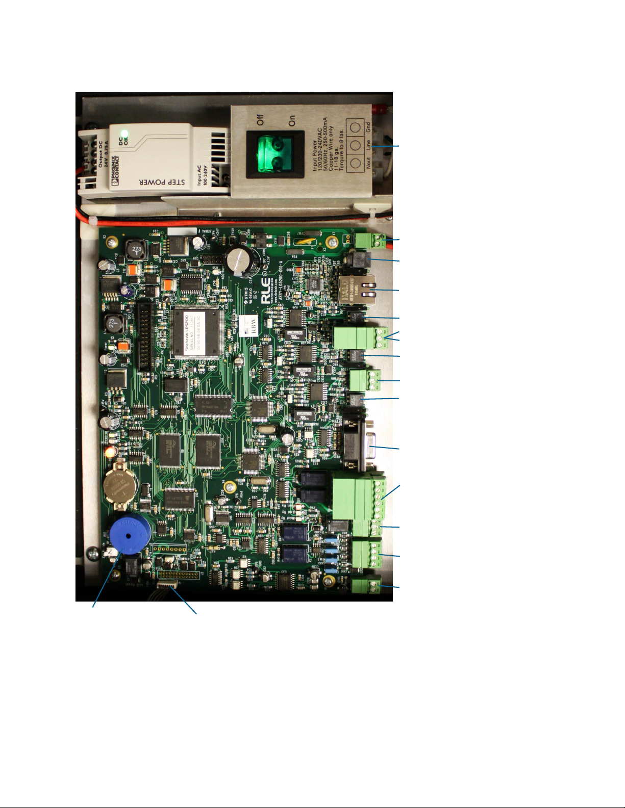
TB4 - (2) Form C Leak Relay Outputs
TB3 - Form C Maintenance Relay
TB1 - 4-20mA Output
TB2 - Cable Interface (W-B-G-R)
P1 - EIA-232 Connector
SW1 - EIA-485 Port 3 Termination
SW2 - EIA-485 Port 2 Termination
SW3 - EIA-485 Port 1 Termination
P2 - Ethernet Jack
TB7 - Input Power
TB5 - EIA-485 Port 3
TB6 Top - EIA-485 Port 1
TB6 Bottom - EIA-485 Port 2
SA1 - Audible Alarm
J4 - LCD Connection
P3 - Optional Power Connection
Power Input Terminal Block
(2) Form C Fault Relay Outputs
and
2 Installation
Figure 2.2
LD5200 Physical Connections and Switches
rletech.com LD5200 User Guide 17
Page 18
2 Installation
2.3.1 TB1: 4-20mA Output
The 4-20mA analog output allows the LD5200 to communicate with a 4-20mA loop powered
output. This connection is provided on TB1. The maximum range (20 mA) can be set to 1000,
2500, or 5000 feet. Connect the 4-20mA wires to TB1 as follows:
TB1-1 4-20mA positive (+)
TB1-2 4-20mA negative (-)
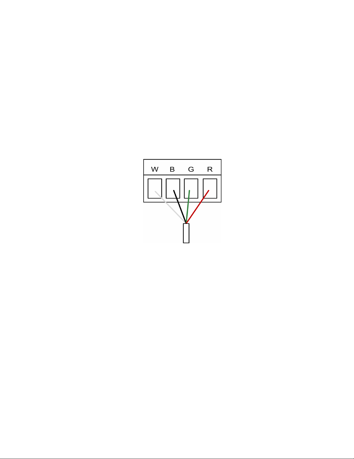
2.3.2 TB2: Sensing Cable Interface
A 15-foot (4.57m) section of non-sensing cable is supplied with each LD5200. The leader
cable connects sensing cable to the LD5200, since sensing cable cannot connect directly to the
unit. Insert its four stripped wires into the appropriate slots in TB2 - from left to right: white,
black, green and red.
TB2-1 White wire
TB2-2 Black wire
TB2-3 Green wire
TB2-4 Red wire
Figure 2.3
NOTE If the terminal connector is removed from the end of the cable, make sure the wires are in the
same order, W - B - G - R, when the connector is reapplied.
For further information regarding sensing cable, refer to “Connect the SeaHawk Sensing
Cable” on page 21.
Cable Connection TB2
2.3.3 TB3: Maintenance Relay
Maintenance reminders can be configured through the LCD or the web interface. This relay
(TB3) is activated once the scheduled maintenance period has lapsed. If you wish, connect this
relay output to a BMS or NMS to monitor regularly scheduled maintenance intervals.
2.3.4 TB4: Two Fault/Leak Relay Outputs
TB4 houses two Form C relay outputs. These relays provide alarm notification when a leak,
cable fault, or cable contamination is detected.
The top row of TB4 (pins 1 - 6) provides a connection to one of the leak alarm relay outputs
and one of the fault relay outputs; the bottom row of TB5 (pins 7 - 12) provides a second set of
contacts for the same leak and fault alarms.
18 LD5200 User Guide 800.518.1519
Page 19

Connect the alarm relay wires to TB4 as follows:
TB4-1 Leak alarm normally open (NO)
TB4-2 Leak alarm common (C)
TB4-3 Leak alarm normally closed (NC)
TB4-4 Fault alarm normally open (NO)
TB4-5 Fault alarm common (C)
TB4-6 Fault alarm normally closed (NC)
TB4-7 Leak alarm normally open (NO)
TB4-8 Leak alarm common (C)
TB4-9 Leak alarm normally closed (NC)
TB4-10 Fault alarm normally open (NO)
TB4-11 Fault alarm common (C)
TB4-12 Fault alarm normally closed (NC)
Both relays (all alarms) can be configured to be latched or unlatched. A latched alarm requires
a manual reset of the system once a leak or cable problem is no longer present; see “Leak” on
page 50 for configuration instructions.
2.3.5 P1: EIA-232 Connector
2 Installation
An EIA-232 connection allows the LD5200 to be connected directly to a terminal or PC. The
EIA-232 uses a baud rate of 9600. The EIA-232 port is set to 8 databits, no parity, and 1 stop
bit (8, N, 1). A straight through cable should be used to connect a terminal or PC to the
LD5200 via the EIA-232 connector. This connection should only be used by advanced users
for specialized operations, including advanced diagnostics, uploading firmware, and
troubleshooting.
2.3.6 SW1: TB5 Port 3 Termination Switch
The switch position numbered 2 on SW1, when switched on (down position), places a
termination resistor across the + and - terminals of the EIA-485 port. This is used when the
TB5 connection on the LD5200 is the last unit on a EIA-485 network. SW1, switch position 1,
is currently inactive.
2.3.7 TB5 and TB6: EIA-485 Modbus Ports
TB5 and TB6 connect to an EIA-485 network. A grounded shield contact is provided for
connection to shielded cable. If the shield contact is used, verify the power connector is
properly grounded and there is no voltage potential between units on the network.The EIA485 ports have a selectable baud rate (9600, 19200, or 38400) and are set to 8 databits, no
parity, and 1 stop bit (8, N, 1). Connect the EIA-485 wires to TB5 and TB6 as follows:
TB5, EIA-485 port 3
TB5-1 A (+)
TB5-2 B (-)
TB5-3 Shield
TB6 (top row) EIA-485 port 1
TB6-1 A (+)
TB6-2 B (-)
TB6-3 Shield
rletech.com LD5200 User Guide 19
Page 20

2 Installation
TB6 (bottom row) EIA-485 port 2
TB6-4 A (+)
TB6-5 B (-)
TB6-6 Shield
2.3.8 SW2: TB6 Port 2 (Bottom Row) Termination Switch
The switch position numbered 2 on SW2, when switched on (down position), places a
termination resistor across the + and - terminals of the EIA-485 port. This is used when the
TB6 (bottom row) connection on the LD5200 is the last unit on a EIA-485 network. SW2,
switch position 1, is currently inactive.
2.3.9 SW3: TB6 Port 1 (Top Row) Termination Switch
The switch position numbered 2 on SW3, when switched on (down position), places a
termination resistor across the + and - terminals of the EIA-485 port. This is used when the
TB6 (top row) connection on the LD5200 is the last unit on a EIA-485 network. SW3, switch
position 1, is currently inactive.
2.3.10 P2: RJ45 Network
This 10/100 BaseT Ethernet connection allows the LD5200 to be connected directly to a local
area network. Use a crossover cable (shipped with the LD5200; blue cable with yellow ends)
for initial connection and configuration. The default settings are as follows:
IP Address: 10.0.0.188
Subnet Mask: 255.255.255.0
Default Gateway: 10.0.0.1
2.3.11 P3: Optional Power Connection
If a mechanical failure causes the provided AC power supply and connections to fail, a wall
adapter can be plugged into P3 and used to power the LD5200. This option is provided for
temporary, emergency situations only, and is not intended as a permanent power solution.
2.3.12 TB7: Input Power (from Input AC Power Supply)
TB7 is a factory-wired two position connector with the following connections (for reference
only):
TB7-1 24VDC positive (+)
TB7-2 24VDC negative (-)
2.3.13 DS1: Status LED
A status LED is located at the top of the main board, and is labeled DS1. Indicators are as
follows:
Green - LD5200 is functioning properly
Red - LD5200 is in an alarm state
Yellow (flashing) - The LD5200’s bootloader is operational
20 LD5200 User Guide 800.518.1519
Page 21
2 Installation
2.4 Connect the SeaHawk Sensing Cable
IMPORTANT To avoid faulty leak detection readings, connect a minimum length of 35 feet (10.7m) of
sensing cable to the LD5200.
The LD5200 is shipped with a 15-foot (4.57m) leader cable. This leader cable was connected
to the LD5200 in Section 2.3.2 on page 18. The following directions will help you connect
sensing cable to the LD5200.
2.4.1 Connect Lengths of Sensing Cable
1 Unscrew the end-of-line (EOL) terminator from the end of the leader cable.
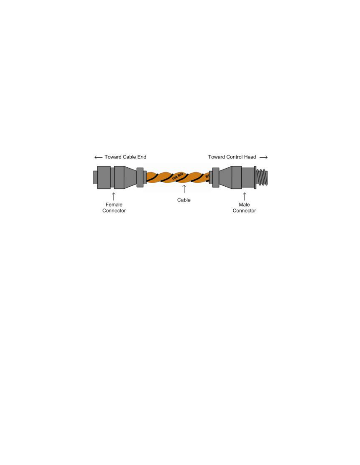
2 Attach the first length of sensing cable to the leader cable. Insert the male connector into the
female connector, and twist the collar on the female side of the connector to secure.
Figure 2.4
3
Route the sensing cable according to your cable layout diagram. Attach additional lengths
SeaHawk Sensing Cable
of sensing cable as necessary.
4 Secure the EOL terminator to the unoccupied end of the last length of sensing cable.
Note If the EOL terminator is not present at the end of the cable run, a cable fault will register.
5
If you are using a reference map, compare it with the actual cable installation. Revise any
discrepancies created through the physical installation of the cable.
2.4.2 Secure Sensing Cable to the Floor
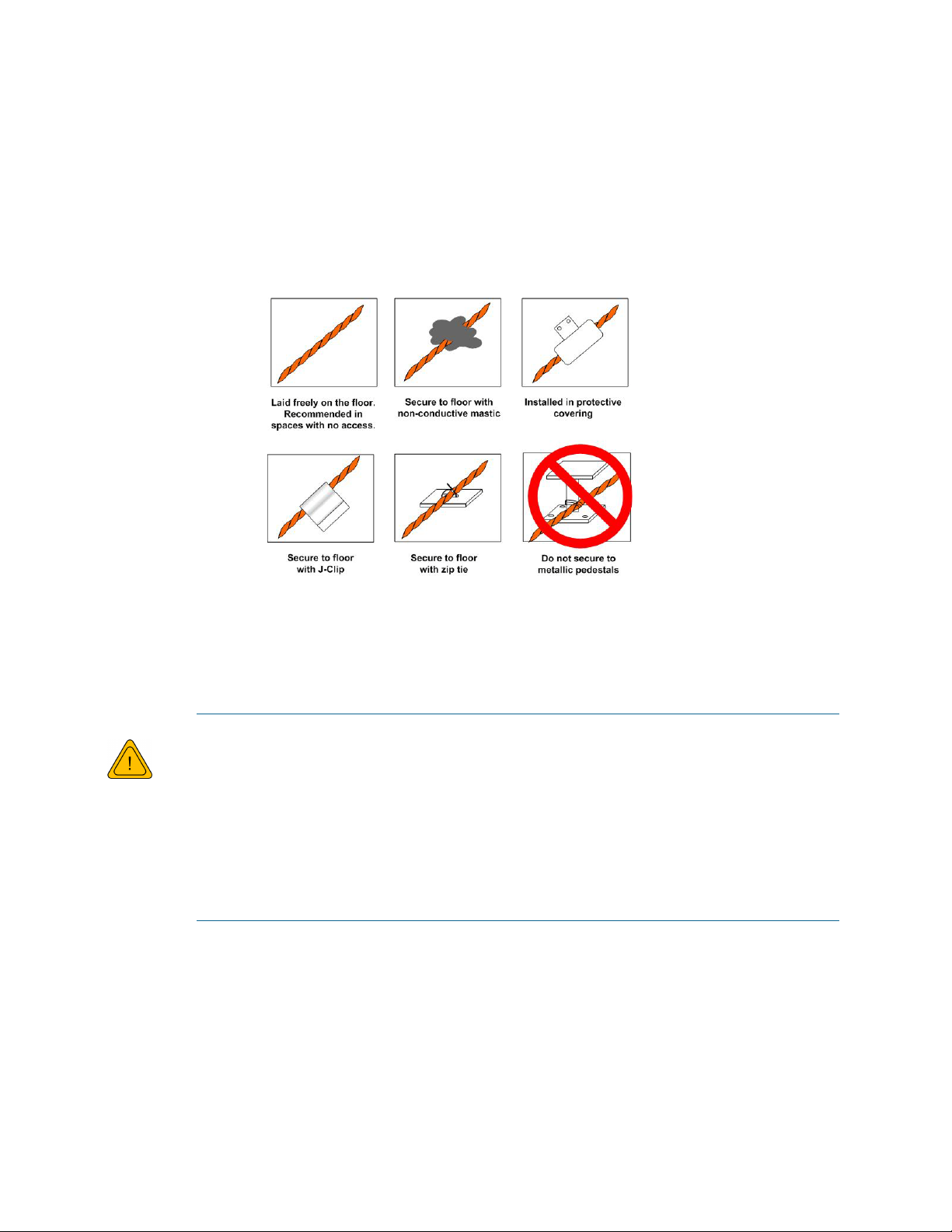
Secure the sensing cable to the floor with either J-clips (RLE part #JC), or one of the other
approved methods shown in Figure 2.5. Available from RLE and designed specifically for use
with sensing cable, J-clips are the manufacturer's recommended installation method.
♦ Do not use conductive materials, such as Fire Block or caulk, on the sensing cable.
♦ To avoid contaminating the cable, clean the entire floor as much as possible. Use isopropyl
alcohol to clean the spots on the floor where J-clips will be placed.
♦ Place one J-clip every 5 to 6 feet (1.52 to 1.83m) along the length of the sensing cable and
one at each turn of the cable. Use more J-clips if a tighter configuration is required.
♦ If the cable is installed over an obstruction, clip the cable on both sides, as close to the
obstruction as possible.
rletech.com LD5200 User Guide 21
Page 22
2 Installation
WARNING
♦ The J-clip’s adhesive backing does not work well on porous concrete floors. RLE
recommends using a drop of silicone or another nonconductive adhesive to help secure the
J-clip to the floor.
IMPORTANT Do not install the cable directly in front of an air conditioner. Allow a minimum of 4 to 6 feet
(1.22 to 1.83m) between the unit and the cable. If the cable is too close to the air conditioning
unit’s air stream, the moisture from the humidifier may cause false leak readings. If the cable
must be installed in front of an air conditioning unit, place the J-clips 3 feet (0.91m) apart.
.
Figure 2.5
Secure the Cable
2.5 Apply Power to the LD5200
A dedicated circuit breaker must be provided within close proximity to the LD5200
and be clearly marked as the disconnecting device for the LD5200 leak detection
controller.
Do not connect 120/230 VAC directly to the unit, or damage will occur to the
circuitry.
Make sure the dedicated circuit breaker is in the off position before connecting the
AC power wires to the LD5200.
1 Engage a certified electrician to run a power supply and necessary conduit to the location of
the LD5200.
2 Remove any necessary knock-outs from the bottom of the enclosure, and route the power
supply into the enclosure, to the power input terminal block. Insert the wires as noted on the
enclosure’s backplate: Neutral - Line - Ground. Ensure all connections are correct and all
screw terminals are tightened and secure.
3 Apply power to the LD5200. The device will boot (initialize).
22 LD5200 User Guide 800.518.1519
Page 23

2 Installation
4 When the LD5200 powers up, diagnostics are performed. The program code is verified.
Once the diagnostics are complete, the LCD displays the Main Menu. No alarm should be
present. If an alarm is present, verify all connections and consult Appendix D,
“Troubleshooting” on page 109.
2.6 Configure Communications
Use the LCD touch screen on the front of the LD5200 to configure communications.
IMPORTANT Consult your IT department before performing these steps. If you intend to change the IP
Address and/or Subnet Mask, obtain appropriate addresses from your IT department.
LD5200 default IP address: 10.0.0.188
LD5200 default subnet mask: 255.255.255.0
LD5200 default gateway: 10.0.0.1
2.6.1 Access the Configuration Menu
1 Push the Setup button on the LD5200’s LCD.
2 You’ll be prompted to enter a password. By default, there is no password on the LD5200.
To continue past the login screen, leave the password field blank and press the Enter button
(
).
You can establish an LCD password through either the LCD interface (“Leak Settings” on
page 37) or the web interface (Chapter 4, “Leak” on page 50).
3 You’ll see the LD5200 Setup Menu. Press the Down button until the System Settings option
is highlighted in blue. Press the Select button to access the System Setup Menu.
4 Push the Down button until the IP address is highlighted. By default, the IP address is
10.0.0.188. Press the Select button to change the IP address.
5 Use the backspace button () to delete the current IP address. Enter the new IP address
for the unit, as provided by your Network Administrator. Press the Enter button to apply the
new IP Address.
6 Scroll down to the Net Mask, and use the same method to edit the Subnet Mask information
as necessary.
rletech.com LD5200 User Guide 23
Page 24

2 Installation
2.7 Test the System
Note If the LD5200 is already connected to a BMS or NMS, notify monitoring personnel before you
begin testing the system.
1 Using a sketch or mechanical drawing of the facility, add the cable routing, connection
points, and any accessories used. Record the distance marker when the cable changes
direction and in between connectors.
The more details you show, the greater the benefit later when you are locating leaks and
troubleshooting the system
2 To verify the LD5200’s accuracy, test three points within the length of sensing cable - one
at the beginning, one in the middle of the length, and another near the end of the length of
cable.
There are a variety of ways to simulate a leak:
♦ Pour a small puddle of water on the
cable while it rests on the floor.
♦ Dunk the cable in a cup of water.
♦ Soak a paper towel or rag and wrap it
loosely around the cable. This is
popular if the cable is used in pipe
applications. Be careful to wrap the
wet cloth loosely around the cable.
Do not put pressure on the cable.
IMPORTANT - To avoid inaccurate
readings, do not grip the cable with
your hand.
Figure 2.6
3 Verify that the LD5200 reports the leaks within a few feet of their actual physical location.
4 Remove the simulated leak source and return the system to its normal operating state.
Apply Moisture to the Cable for Testing Purposes
24 LD5200 User Guide 800.518.1519
Page 25
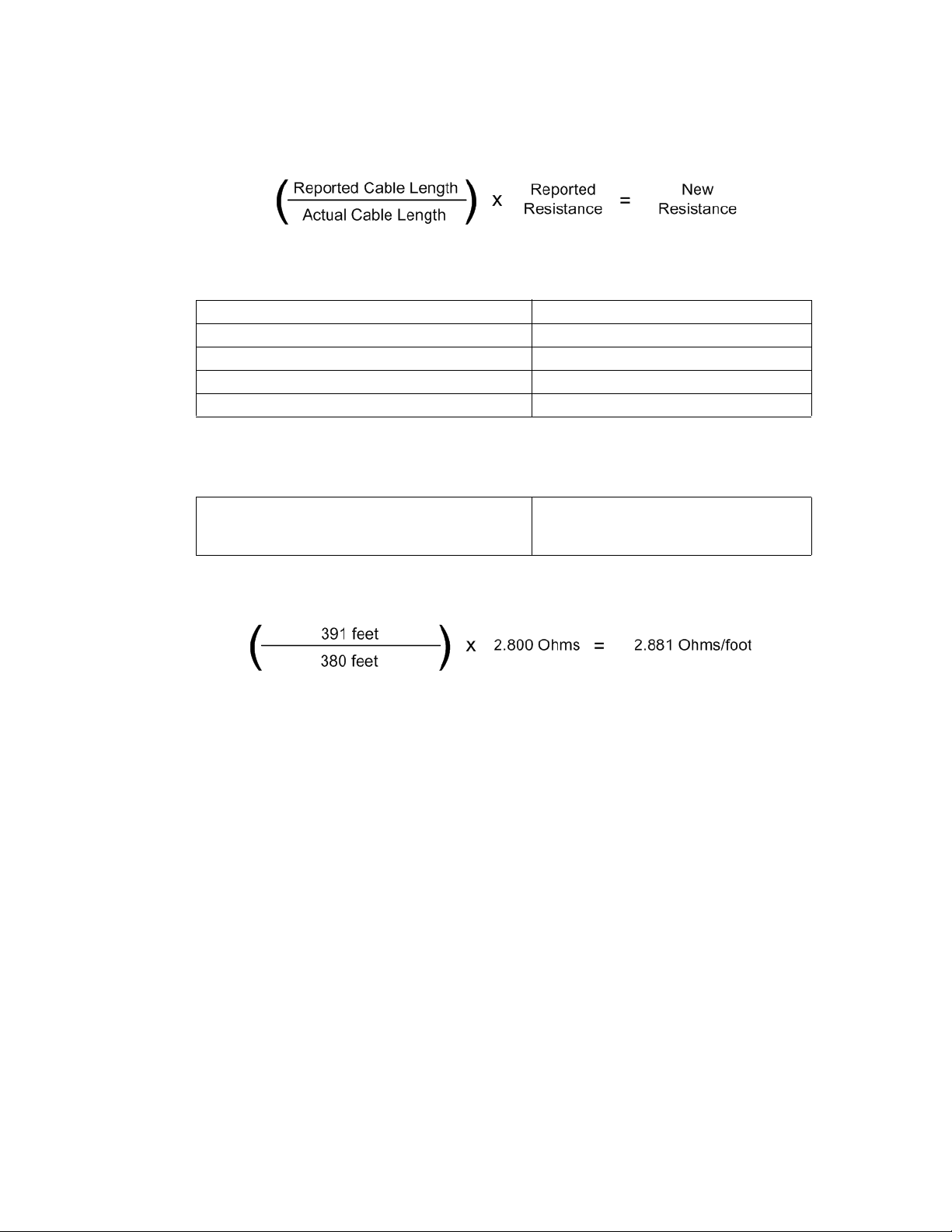
2.8 Calibrate Cable Resistance
Distance-read leak detection systems are resistance-based. RLE’s orange water sensing cable
has a base resistance of 2.8 ohms/foot, while most other sensing cables, including RLE’s green
chemical resistant sensing cable, have a resistance of 4.0 ohms/foot.
The resistance of each length of sensing cable may be slightly more or less than the base
resistance due to manufacturing variances. For this reason, the cable length displayed on the
home page of the web interface and on the status screen of the LCD may be slightly more or
less than the actual length of cable installed.
A system configured using base resistance values will still be very accurate. If you wish to fine
tune the resistance value of your LD5200 system to make it more precise, you may do so. This
will increase the accuracy of the system, and bring the LD5200’s reported installed cable
length value in line with the actual length of cable installed.
1 Ensure the LD5200 has been powered and has all the sensing cable attached to it, with no
alarms present.
2 Gather and record the following data from either the home page of the web interface or the
status page of the LCD:
2 Installation
Cable Length (as reported by the LD5200)
Cable Current
Leg 1 Resistance
Leg 2 Resistance
Record the resistance per foot setting, as reported by the LD5200. This can be found on the
Leak Configuration page of the web interface (Configuration > Leak Settings) or on the
Leak Settings screen of the LCD (Setup > Leak Settings).
Reported Resistance per Foot
3 Note the actual (physical + simulated) length of cable physically connected to the system.
For your reference:
♦ WCCS simulates 50 ft. ♦ XCON simulates 150 ft.
♦ SDZ simulates 50 ft. ♦ Nonsensing cable does not add
any length to a system
Record this sum:
Actual length of cable connected to LD5200
4 Verify the current reading on the cable from your recorded values above. This value must
be less than 15 μA in order to calibrate the system. If the current is higher than 15μA, clean
the cable. Isopropyl alcohol works well to remove any contamination that might have
gotten onto the cable during installation.
rletech.com LD5200 User Guide 25
Page 26
2 Installation
5 To calculate the most accurate resistance value for the system, divide the reported cable
length by the actual cable length, and multiply the quotient by the reported resistance.
For example:
Cable Length (as reported by the LD5200) 391 feet
Cable Current 0 μA
Leg 1 Resistance 1088 Ohms
Leg 2 Resistance 1095 Ohms
Reported Resistance 2.800 Ohms/foot
One 15 foot leader cable (leader cable does not count toward the total length of cable
installed), one weighted cable connector (simulates 50 feet of cable), and one 330 foot
section of cable are connected to the system.
Actual length of cable connected to LD5200
380 feet
0 feet + 50 feet + 330 feet
The actual resistance of the cable installed with this LD5200 is 2.881 ohms per foot.
6 Replace the resistance per foot setting in the LD5200 with this newly calculated value. This
can be edited on the Leak Configuration page of the web interface (Configuration > Leak
Settings) or on the Leak Settings screen of the LCD (Setup > Leak Settings).
When using the web interface, remember to click the Submit Changes button to save the
adjusted resistance value.
In our example, adjusting the resistance value changed the reported cable length from 391
feet to 380 feet. This improves the accuracy of the system because the reported cable length
more closely matches the physical length of cable connected to the system.
26 LD5200 User Guide 800.518.1519
Page 27

2.9 Configure Security Settings
The LD5200 allows users to create a user name for web interface access and set two different
passwords for that user.
The Read Only password allows users to access the LD5200’s web interface and view the
conditions of the system, but does not allow users to make changes to the LD5200’s
configuration.
The Read/Write password provides users with expanded access. This password allows users to
view the conditions of the system and make changes to the LD5200’s configuration.
By default, the LD5200’s username is: ld5200 (case sensitive)
By default, no password is assigned.
To access the web interface, type ld5200 in the User Name field, leave the password field
blank, and press return.
Web interface passwords can only be configured through the web interface. Refer to Chapter
4, “Web” on page 59 for further information.
2 Installation
2.10 General Operation
The LD5200 features both an LCD and a web interface. The LCD is accessible on the front of
the device’s enclosure, and allows users to quickly access, acknowledge, and configure system
settings, alarms, alarm history and device operations. The web interface provides more indepth access to the LD5200, and allows users to accomplish all the same tasks as the LCD,
while addressing some robust, expanded functionality that cannot be utilized through the
LCD.
Both interfaces access the same information and data. If you make changes to the LD5200
through the LCD, the changes will show up on the web interface, and vice versa.
Refer to Chapter 3, “LCD Touch Screen Interface” on page 29 for detailed information
regarding the LCD. Refer to Chapter 4, “Web Interface” on page 47 for detailed information
regarding the web interface.
rletech.com LD5200 User Guide 27
Page 28

2 Installation
28 LD5200 User Guide 800.518.1519
Page 29
C HAPTER
CHAPTER 0LCD TOUCH SCREEN INTERFACE
The LD5200’s LCD touch screen accommodates basic device configuration and operation. All
the functionality you need to operate the LD5200 as a stand-alone device is accessible from the
LCD touch screen.
Virtual buttons line the right side of the screen, and they operate much like mechanical buttons.
Press the button for the task you want to perform, and the screen for that task is displayed.
Avoid using a pen or sharp object to push the buttons - this will damage the LCD.
While button options vary throughout the menus, the most common button structure features
four buttons: Up, Down, Select, and Return. They work as follows:
Button Function
Up Scroll up through the options. The blue highlight indicates
which option you are accessing.
Down Scroll down through the options. The blue highlight indicates
which option you are accessing.
Select Access the blue highlighted option to edit or confirm settings
and data. Press Enter ( ) to submit a value. ( ) is
the backspace. Esc returns to the previous menu.
Return Return to the previous menu.
Table 3.1
LCD - Main Buttons
rletech.com LD5200 User Guide 29
Page 30
3 LCD Touch Screen Interface
LCD - Main Menu
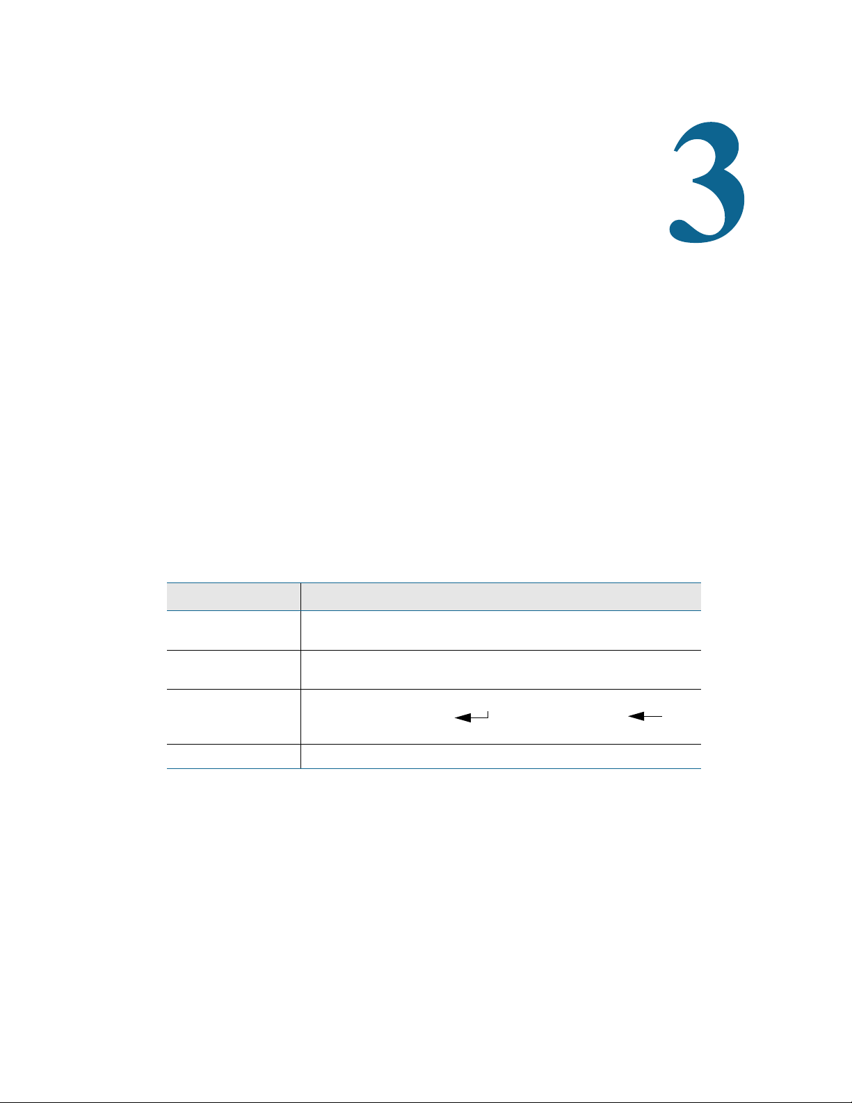
3.1 Main Menu
When the LD5200 powers up,
diagnostics are performed. The boot
ROM and flash program code are
verified. Once the diagnostics are
complete, the LCD displays the Main
Menu.
Any time a screen within the LCD
interface is left idle for more than five
minutes, it will return to this default
display.
The Main Menu features basic system
information including the device
name, current date, time, firmware
version running on the system, and current alarm notification.
Four buttons run down the right side of the LCD and function as follows:
Button Function
Silence Silence the audible
alarm
Alarms List current alarms Display alarm history, acknowledge
Status View status information
for master and all slave
units
Setup Access and configure a
wide variety of system
options
Table 3.2
LCD Main Menu Buttons
3.2 Silence Button
The Silence button silences the audible alarm. Press the button once to silence the alarm.
Additional Options Accessible
Through Sub-Menus
No additional options
alarms.
View network statistics, EIA-485
data, and the leakage trend log for
master and all slave units
Leak settings, virtual zones, slave
zones, 4-20mA output, preventative
maintenance, system settings, EIA485 / Modbus / N2 configuration,
BACnet configuration, and clear
alarm and trend log history
30 LD5200 User Guide 800.518.1519
Page 31

3.3 Alarms Button
LCD - Current Alarms
The Alarms option allows users to
display current alarms and alarm
history.
Alarms are color coded as follows:
Color Description
Red Active alarm - leak detected
Yellow Active alarm - cable break or contamination detected
3 LCD Touch Screen Interface
Orange Active alarm - communications problem - one of the monitored
slave devices is offline
Table 3.3
LCD Current Alarm Color Codes
Four buttons run down the right side of the LCD and function as follows:
Additional Options Accessible
Button Function
Next Advance to the next
page of current alarms
Previous Go back to the previous
page of current alarms
History View alarm history and
acknowledge all
unacknowledged alarms
Return Return to the Current
Alarms page.
Table 3.4
LCD Current Alarm Buttons
Through Sub-Menus
No additional options
No additional options
Access the Alarm History screens.
Return to the Main Menu
rletech.com LD5200 User Guide 31
Page 32

3 LCD Touch Screen Interface
LCD - Alarm History
3.3.1 History
Color Description
Red Unacknowledged alarm
Blue Acknowledged alarm
Push this button to display the alarm
history. The LD5200 logs the last
1024 alarm events.
Alarm history data is color coded
as follows:
Black Alarm condition has returned to normal, or additional
information is provided regarding the LD5200’s functionality
Table 3.5
LCD Alarm History Color Codes
Use the Next, Previous, and Return buttons to navigate through the alarm history.Four buttons
run down the right side of the LCD and function as follows:
Additional Options Accessible
Button Function
Next Advance to the next
page of alarm history
Previous Go back to the previous
page of alarm history
Ack Acknowledge all
unacknowledged alarms
on the current alarm
history page
Return Return to the Current
Alarms page.
Table 3.6
LCD Alarm History Buttons
Through Sub-Menus
No additional options
No additional options
No additional options
No additional options
32 LD5200 User Guide 800.518.1519
Page 33

3.4 Status Button
LCD - Controller Status
The Status button allows you to view
current controller status information.
Most of these values can be adjusted
through the Setup button on the main
page of the LCD. The Status page is
intended for reference only, not
system adjustment.
Attribute Description
Alarm Status If the controller is in an alarm state, details regarding the alarm
are noted in this field. The field is also color coded to indicate
the type of alarm.
3 LCD Touch Screen Interface
Cable Length The length of sensing cable connected to the controller, as
calculated by the LD5200
Cable Current The amount of current running on the sensing cable
Leg 1 Resistance The resistance of Leg 1 is displayed in Ohms.
Leg 2 Resistance The resistance of Leg 2 is displayed in Ohms.
Leak Alarm Delay The amount of time that passes between the time a leak is
detected and the annunciation of the leak alarm.
Contamination
Alarm Delay
Re-alarm
Countdown
Last Alarm Time A record of the last time the system detected an alarm
sysUpTime The amount of time that has passed since the system was last
Table 3.7
LCD Controller Status Information Fields
The amount of time that passes between the time a
contamination is detected and the annunciation of that alarm.
The amount of time remaining until the active alarm is reannunciated.
condition.
reset or powered on.
rletech.com LD5200 User Guide 33
Page 34

3 LCD Touch Screen Interface
This menu features four buttons: Next, Previous, System, and Return:
Button Function
Next If multiple controllers are
Additional Options Accessible
Through Sub-Menus
networked through a
master device, push this
button to view the next
monitored controller.
Previous View the previous
controller in the list of
monitored devices
System View additional system
information
Return Return to the Current
Alarms page.
Table 3.8
LCD Controller Status Buttons
No additional options
Network, EIA-485, Trend, Return
No additional options
34 LD5200 User Guide 800.518.1519
Page 35

3.4.1 System Button
LCD - System Status
View the system status information
for the selected controller. Here you
will find a variety of information for
the device, including the device’s
model number, firmware version,
MAC and IP addresses, subnet mask,
default gateway, and the amount of
time the device has been running
since it last lost power. A majority of
this information is editable through
the Setup button on the LCD’s main
page. This page is intended for
reference.
This option features four buttons: Network, EIA-485, Trend, and Return.
Option Description
3 LCD Touch Screen Interface
Additional Options Accessible
Through Sub-Menus
Network View network statistics
for the selected
controller.
EIA-485 View statistics for the
three EIA-485 ports.
Trend View the leakage trend
log. The log catalogs the
last 365 entries.
Return Return to the Status
page.
Table 3.9
LCD System Status Button Options
Reset: Reset the numerical values
for all monitored fields in the list to
0.
Return: Return to the System page
for the selected controller.
Reset: Reset the numerical values
for all monitored fields in the list to
0.
Return: Return to the System page
for the selected controller.
Next: View the next page of logged
data.
Previous: View the previous page of
logged data.
Return: Return to the System page
for the selected controller.
rletech.com LD5200 User Guide 35
Page 36

3 LCD Touch Screen Interface
LCD - Password Screen
LCD - Setup Menu
3.5 Setup Button
The Setup button provides access to a
wide variety of settings, including:
leak settings, virtual and slave zone
settings, 4-20mA output settings,
preventative maintenance options,
system setting, EIA-485/modbus/N2
settings, and BACnet options. The
clear history buttons are also located
within the Setup options.
The Setup options can be password
protected. By default, there is no
password assigned. The password
screen will pop up even if no
password is applied to the controller.
Press the enter key
through the password screen if no
password has been assigned.
() to pass
Use the buttons on the right side of
the LCD to navigate through the
menus. The blue highlight indicates
which option is selected. Use the
buttons on the right side of the LCD
to navigate through the menus. Press
the Select button to choose the blue
highlighted option.
36 LD5200 User Guide 800.518.1519
Page 37
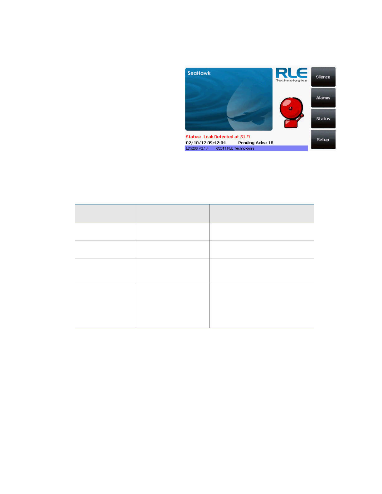
3.5.1 Leak Settings
LCD - Leak Settings
Leak Settings allows you to fine tune
the leak detection options available
on the LD5200. Use the Up, Down,
Select and Return buttons to
navigate through the leak settings
menu.
Option Description
Leak Trip Point The threshold for the amount of water required to trigger a leak
3 LCD Touch Screen Interface
alarm. Adjust this number to adjust the sensitivity of the leak
alarm.
A lower number yields a more sensitive system, so the system
will trigger a leak alarm with less water present.
A higher number produces a less sensitive system, so more
water is required to trigger an alarm.
Enter a value between 25 and 175 microamps.
Default setting: 150uA.
Contamination Trip
Point
Leak Alarm Delay The amount of time that passes between the time a leak is
The threshold for the amount of contamination required to
trigger a cable contamination alarm. Adjust this number to
adjust the sensitivity of the contamination alarm.
A lower number yields a more sensitive system, so the system
will trigger a contamination alarm with less contamination
present.
A higher number produces a less sensitive system, so more
contamination is required to trigger an alarm.
Enter a value between 20 and 175 microamps.
Default setting: 50uA.
detected and the annunciation of the leak alarm. The leak trip
point must be exceeded for the duration of this delay.
Enter a value between 5 and 990 seconds.
Default setting: 20 seconds
Table 3.10
rletech.com LD5200 User Guide 37
LCD Leak Settings - Configurable Options
Page 38

3 LCD Touch Screen Interface
Option Description
Contamination
Alarm Delay
Resistance Per
Foot
The amount of time that passes between the time a
contamination is detected and the annunciation of the
contamination alarm. The contamination trip point must be
exceeded for the duration of this delay.
Enter a value between 5 and 990 seconds.
Default setting: 40 seconds
The resistance per foot of cable determines the LD5200’s
ability to accurately detect the cable length installed and
calculate distances to leaks. Adjust this value to fine-tune the
accuracy of a distance-read leak detection system.
RLE’s orange water sensing cable has a base resistance of
2.800 ohms per foot. Most other sensing cables, including
RLE’s green chemical-resistant sensing cable, have a base
resistance of 4.000 ohms per foot. Consult the sensing cable’s
datasheet for further information.
Refer to “Calibrate Cable Resistance” on page 25 for detailed
resistance calibration.
The resistance value must be entered as a 4-digit number
between 2.000 and 4.250, with one number in the tens place
and three numbers past the decimal point (x.xxx).
Default setting: 2.800 ohms per foot.
Re-Alarm Delay The LD5200 can be set to re-alarm - after a leak or
contamination has been detected, the alarm will be re-sent at a
defined interval until the alarm condition has been resolved.
The re-alarm triggers both the audible alarm and the direct
notification alarm.
The interval is adjustable in whole hour increments. Decimal
values are not allowed. Enter a number from 0 to 24. A 0 in this
field turns off the re-alarm option, so only one alarm notification
will be sent for each alarm.
Default setting: 0 (disabled)
Measurement
Display
Select either feet or meters to calibrate the LD5200 to the
preferred unit of measure. All distance calculations will adjust
accordingly.
Default setting: Feet
Table 3.10
LCD Leak Settings - Configurable Options
38 LD5200 User Guide 800.518.1519
Page 39

3 LCD Touch Screen Interface
Option Description
Latching Alarms A non-latching alarm resets itself once a detected leak or
contamination has been resolved.
A latching alarm must be manually acknowledged before its
annunciation clears, even if the detected leak or cable problem
is no longer present.
Select Yes (latching) or No (non-latching).
Default setting: No (non-latching alarms)
Audible Alarm Select Yes to activate the audible alarm annunciation. Select
No to deactivate the audible alarm annunciation.
Default setting: No (audible alarm disabled)
LCD Password Establish a 4-digit numerical password to restrict access to the
Setup series of menus. Set the value to 0000 to disable
password protection.
Table 3.10
Default setting: 0000 (no password)
LCD Leak Settings - Configurable Options
rletech.com LD5200 User Guide 39
Page 40

3 LCD Touch Screen Interface
LCD - Virtual Zone Settings Menu
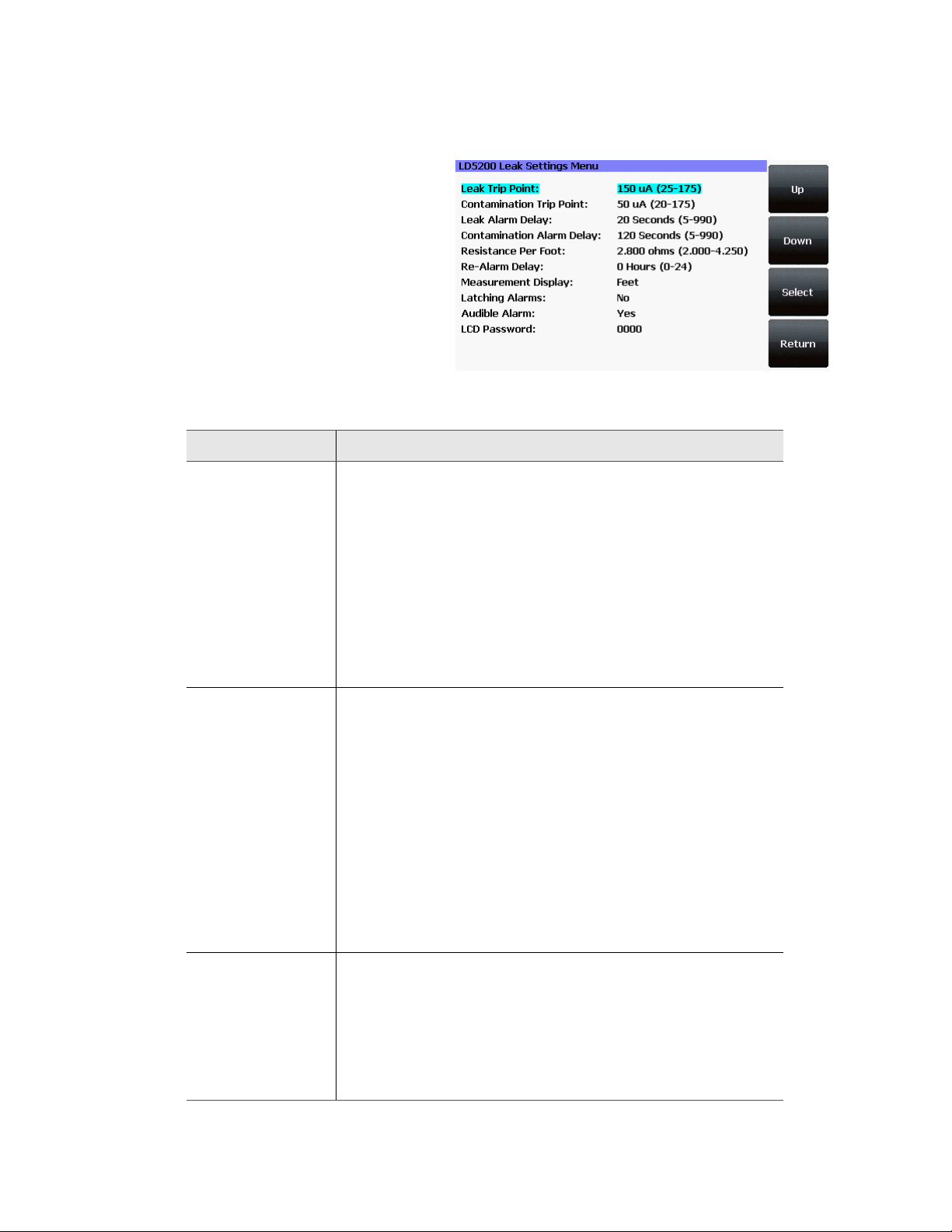
3.5.2 Virtual Zone
A virtual zone is a labeled reference point in a leak detection system. A virtual zone can consist
of a room, a drip pan containing a spot detector under an air handler unit, a combination of
rooms and components, or any other defined area whose identification would help in the
location of leaks.
The LD5200 allows you to establish
up to 32 virtual leak detection zones.
Dividing a leak detection system into
zones helps locate leaks quickly. It
simplifies troubleshooting by
allowing you to isolate different
sections of cable as separately
defined areas. Use the Virtual Zone
Settings page to configure the
LD5200’s virtual zones
Use the Up, Down, Select and Return
buttons to navigate through the
virtual zone menus.
Push the Select button to choose the blue highlighted zone you wish to configure or edit. Use
the LCD keyboard to give the zone a descriptive identifier. Push the Return button and log the
end distance for that particular virtual zone. To delete a virtual zone, select the zone and delete
the text from all fields.
Option Description
# A fixed number, 1 - 32, used to designate the Zone.
Label A descriptive label for the zone, 30 characters or less.
End Distance Record the sensing cable’s distance measurement at the END
of the zone.
Zone 1 starts at 0 feet / meters, and you designate the end
point for Zone 1. Zone 2 starts at zone 1’s ending distance; you
designate where Zone 2 ends. Each subsequent zone begins
where the previous zone ends.
Table 3.11
LCD Virtual Zone Settings - Configurable Options
40 LD5200 User Guide 800.518.1519
Page 41

3.5.3 Slave Zone
LCD - Slave Zone Settings Menu
LCD - Slave Zone Setup Menu - Bacnet
LCD - Slave Zone Setup Menu- Modbus
Slave zones are secondary physical
controllers that report to the LD5200.
Zone controllers and distance-read
controllers can be networked as
slaves to a master LD5200. Up to 128
slave devices can report to one
LD5200.
3 LCD Touch Screen Interface
Option Description
Slave Zone # Non-editable; defined by the blue highlighted device you chose
to configure.
Label Enter a name for the slave controller, 30 characters or less.
Controller Type Designate the slave device as zone or distance read
Comm Type Select a communications type for the slave device:
Comms Disabled
EIA-485 port 1
EIA-485 Port 2
EIA-485 Port 3
Modbus/TCP
Modbus/UDP
Bacnet/IP
Slave ID Designate the Slave ID or Device ID
IP Address Enter the IP Address of the slave device.
V-Zone Label the virtual zones. A device communicating via Modbus
will have editable zone names and end distances. A device
communicating via Bacnet will be read-only - the LD5200 will
obtain the information from the other controller.
Table 3.12
LCD Slave Zones Setup - Configurable Options
rletech.com LD5200 User Guide 41
Page 42

3 LCD Touch Screen Interface
LCD - 4-20mA Output Settings Menu
3.5.4 4-20mA Output
The 4-20mA output only reports up
to 5,000 feet of sensing cable.
Option Description
Leak Alarm Output
Span
Leak Alarm Output
Range
Table 3.13
LCD 4-20mA Settings - Configurable Options
Selectable:
5-19 mA (default)
4-20 mA
Selectable:
1000 (default)
2500
5000
42 LD5200 User Guide 800.518.1519
Page 43

3.5.5 Preventative Maintenance
LCD - Preventative Maintenance Menu
Preventative maintenance keeps a
leak detection system running
efficiently and reliably. Use this
option to program a preventative
maintenance alarm reminder into the
system.
Option Description
PM Alarm every: Select a span of days to elapse between maintenance alarms,
from 30-720 days. Set the value to 0 to disable this option.
3 LCD Touch Screen Interface
Default setting: 0 (disabled)
LCD Acknowledge
Code
Text Designate text to display when the maintenance reminder is
Table 3.14
LCD Preventative Maintenance - Configurable Options
Establish a 4-digit numerical code to acknowledge the
preventative maintenance alarm. Set the value to 0000 if you
don’t wish to have a password.
Default setting: 0000 (no password)
triggered.
Enter up to four lines of text (30 characters per line)
rletech.com LD5200 User Guide 43
Page 44

3 LCD Touch Screen Interface
LCD - System Setup Menu
3.5.6 System Settings
A variety of settings are available to
make your LD5200 easy to identify.
Use this option to edit the system
information.
Option Description
System Name Designate a unique name for the LD5200, up to 30 characters.
Date Adjust the current date, in mm/dd/yy format, if necessary.
Time Adjust the current time, in hh:mm:ss format, if necessary.
IP Address Set the IP address for the LD5200, so it can communicate on
your network. If you do not have an IP address for the device,
obtain one from your IT department.
Default IP address: 10.0.0.188
Def. Route Designate the device’s default route (default gateway). If you
do not have a default route, obtain one from your IT
department.
Default device route: 10.0.0.1
Net Mask Designate the device’s Subnet Mask. Contact your IT
department for further information.
Default subnet mask: 255.255.255.0
MAC Address The MAC address is a unique identifier set by the
manufacturer, and is non-editable.
Table 3.15
LCD System Settings - Configurable Options
44 LD5200 User Guide 800.518.1519
Page 45

3.5.7 EIA-485 / Modbus / N2
LCD - EIA485/Modbus/N2 Setup Menu
If the LD5200 will be
communicating via the EIA-485
port, configure the necessary options
here.
Menu selections are as follows:
Option Description
TCP/UDP UID Set the TCP/UDP unique identifier. this will be a value
between 1 and 254. A value of 0 disables this option.
3 LCD Touch Screen Interface
Alarm Relay Enable or disable the alarm relay.
EIA-485 Port 1 Select Modbus-Slave or Modbus-Master
Port 1 Baud Rate Selectable: 9600, 19200, or 38400
Port 1 Slave Address Set the slave address, 1-254. 0 = disabled.
EIA-485 Port 2 Select Modbus-Slave, Bacnet Ms/Tp Slave, Modbus-
Master, or N2 (fixed, 9600, n,1)
Port 2 Baud Rate Selectable: 9600, 19200, or 38400
Port 2 Slave Address Set the slave address, 1-254. 0 = disabled.
EIA-485 Port 3 Select Modbus-Slave or Modbus-Master
Port 3 Baud Rate Selectable: 9600, 19200, or 38400
Port 3 Slave Address Set the slave address, 1-254. 0 = disabled.
Table 3.16
LCD EIA-485 / Modbus / N2 Setup - Configurable Options
rletech.com LD5200 User Guide 45
Page 46

3 LCD Touch Screen Interface
LCD - Bacnet Setup Menu
3.5.8 Bacnet
The LD5200 can communicate via
BACnet. BACnet allows building
automation and control devices to
communicate, regardless of the
building services they perform.
Use this screen to configure BACnet
options.
Option Description
Device Name Designate a unique name for the LD5200, up to 30 characters.
Device ID Set the device ID, up to 30 characters. 0 = disabled.
Description Enter a description for the device, up to 30 characters.
UDP Port Enter a 0 to specify port 47808 (0xBAC0) as the UDP port. If
Ms/Tp Max Master Represents the number of devices on the EIA-485 string.
Table 3.17
LCD Bacnet Setup - Configurable Options
3.5.9 Clear History
Select this option to clear the Alarm History and Trend Logs.
another port value is specified by your application, enter that
value here.
Default setting: 0
Commonly, the Max Master is set to the same setting as the
BACnet master.
46 LD5200 User Guide 800.518.1519
Page 47

C HAPTER
CHAPTER 3WEB INTERFACE
The LD5200’s LCD accommodates most device control and configuration. For more in-depth
functionality, use the web interface.
To access your LD5200’s web interface, type the device’s IP address into your web browser’s
location bar.
4.1 Home Page
The LD5200’s home page features basic system information, including current alarm status, the
reported length of sensing cable connected to the system, the last time the system went into
alarm, and the running system uptime. The image to the right of the table can be customized,
and can be linked to interactive floor maps.
The row of links inside the blue bar at the top of the page act like tabs, and provide access to a
variety of expanded functionality and configuration options.
Figure 4.1
rletech.com LD5200 User Guide 47
LD5200 Web Interface Home Page
Page 48

4 Web Interface
The home page also provides annunciation for active alarms.
Figure 4.2
LD5200 Web Interface Home Page with Active Leak Detected Alarm
4.2 Identity
The Identity link displays basic LD5200 information, including model number, system name,
contact information, firmware version, and IP address. Most of these values can be adjusted
through the Configuration screens. This page is intended for reference only, not system
adjustment.
Figure 4.3
48 LD5200 User Guide 800.518.1519
Identity Page
Page 49

4.3 Configuration
The Configuration link provides access to a series of sub-menus from which users can adjust
system settings.
4 Web Interface
NOTE
Figure 4.4
Configuration Page
If any of the fields within the sub-menus are edited, be sure to click the Submit
Changes button to save the changes. If you edit the fields and navigate from the
web page without clicking the Submit Changes button, all changes will be lost.
rletech.com LD5200 User Guide 49
Page 50

4 Web Interface
4.3.1 Leak
Use the Leak Configuration page to fine tune system variables, including leak and
contamination thresholds, latching and unlatching alarms, and sensing cable resistance.
Figure 4.5
Leak Configuration Page
50 LD5200 User Guide 800.518.1519
Page 51

4 Web Interface
Option Description
Leak Trip Point The threshold for the amount of water required to trigger a leak
alarm. Adjust this number to adjust the sensitivity of the leak alarm.
A lower number yields a more sensitive system, so the system will
trigger a leak alarm with less water present.
A higher number produces a less sensitive system, so more water
is required to trigger an alarm.
Enter a value between 25 and 175 microamps.
Default setting: 150uA.
Contamination Trip
Point
The threshold for the amount of contamination required to trigger a
cable contamination alarm. Adjust this number to adjust the
sensitivity of the contamination alarm.
A lower number yields a more sensitive system, so the system will
trigger a contamination alarm with less contamination present.
A higher number produces a less sensitive system, so more
contamination is required to trigger an alarm.
Enter a value between 20 and 175 microamps.
Default setting: 50uA.
Leak Alarm Delay The amount of time that passes between the time a leak is detected
and the annunciation of the leak alarm.
The leak trip point must be exceeded for the duration of this delay.
Default setting: 20 seconds
Contamination
Alarm Delay
The amount of time that passes between the time a contamination
is detected and the annunciation of the contamination alarm.
The contamination trip point must be exceeded for the duration of
this delay.
Default setting: 40 seconds
Table 4.1
rletech.com LD5200 User Guide 51
Leak Configuration Options
Page 52

4 Web Interface
Option Description
Resistance Per Foot The resistance per foot (or meter) of cable determines the
LD5200’s ability to accurately detect the cable length installed and
calculate distances to leaks. Adjust this value to fine-tune the
accuracy of a distance-read leak detection system.
RLE’s orange water sensing cable has a base resistance of 2.800
ohms per foot. Most other sensing cables, including RLE’s green
chemical-resistant sensing cable, have a base resistance of 4.000
ohms per foot. Consult the sensing cable’s datasheet for further
information.
Refer to “Calibrate Cable Resistance” on page 25 for detailed
resistance calibration.
The resistance value must be entered as a 4-digit number between
2.000 and 4.250, with one number in the tens place and three
numbers past the decimal point (x.xxx).
Default setting: 2.800 ohms per foot.
Re-Alarm Interval The LD5200 can be set to re-alarm - after a leak or contamination
has been detected, the alarm will be re-sent at a defined interval
until the alarm condition has been resolved. The re-alarm triggers
both the audible alarm and the direct notification alarm.
Enter a number from 0 to 24. A 0 in this field turns off the re-alarm
option, so only one alarm notification will be sent for each alarm.
Default setting: 0 (disabled)
Measurement
Display
Select either feet or meters to calibrate the LD5200 to the preferred
unit of measure. All distance calculations will adjust accordingly.
Default setting: Feet
Latching Alarms A non-latching alarm resets itself once a detected leak or
contamination has been resolved.
A latching alarm must be manually acknowledged before its
annunciation clears, even if the detected leak or cable problem is
no longer present.
Select Yes (latching) or No (non-latching).
Default setting: No (non-latching alarms)
Audible Alarm Select Enabled to activate the audible alarm annunciation. Disable
this option to deactivate the audible alarm annunciation.
Default setting: Disabled
Table 4.1
52 LD5200 User Guide 800.518.1519
Leak Configuration Options (continued)
Page 53

4 Web Interface
Option Description
LCD Password Establish a 4-digit numerical code to access the Setup series of
menus through the LCD. Set the value to 0000 if you don’t wish to
have a password.
Default setting: 0000 (no password)
Length Calibration
Factor
4-20mA Leak Alarm
Output Span
4-20mA Leak Alarm
Output Range
Preventative
Maintenance Alarm
Preventative
Maintenance LCD
Ack Code
Reserved for manufacturer’s use only.
Selectable: 5-19mA or 4-20mA
Default setting: 5-19mA
Selectable:
1000 feet
2500 feet
5000 feet
Default setting: 1000 feet
Preventative maintenance keeps a leak detection system running
efficiently and reliably. Use this option to program a preventative
maintenance alarm reminder into the system.
Select a span of days to elapse between maintenance alarms, from
30-720 days. Set the value to 0 to disable this option.
Default setting: 0 (disabled)
Establish a 4-digit numerical code to acknowledge the preventative
maintenance alarm. Set the value to 0000 if you don’t wish to have
a password.
Default setting: 0000 (no password)
Preventative
Maintenance Text
Table 4.1
Leak Configuration Options (continued)
Designate text to display when the maintenance reminder is
triggered.
Enter up to four lines of text (30 characters per line)
Default setting: blank
Set Cable Relay Button - Use to troubleshoot the controller, this button simulates 8060 ohms
of leak detection cable (approximately 2878 feet of 2.8 ohms/foot cable) for up to 5 minutes.
Push the button and then look at the web interface home page. If the controller is functioning
properly, the cable length will register approximately 2878 feet, and the leg 1 and leg 2
resistance will be approximately 8060 ohms.
rletech.com LD5200 User Guide 53
Page 54
4 Web Interface
4.3.2 Virtual Zone
A virtual zone is a labeled reference point in a leak detection system. A virtual zone can
consist of a room, a drip pan containing a spot detector under an air handler unit, a
combination of rooms and components, or any other defined area whose identification would
help in the location of leaks.
The LD5200 supports up to 32 virtual zones. Dividing a leak detection system into zones helps
locate leaks quickly. It simplifies troubleshooting by allowing you to isolate different sections
of cable as separately defined areas.
Figure 4.6
Option Description
Zone # A fixed number, 1 - 32, used to designate the Zone.
Label Type a descriptive label for the zone, 30 characters or less.
End Distance Record the sensing cable’s distance measurement at the END of
Table 4.2
54 LD5200 User Guide 800.518.1519
Virtual Zone Configuration Page
the zone.
Zone 1 starts at 0 feet / meters, and then you designate the end
point for Zone 1. Zone 2 starts at zone 1’s ending distance; you
designate where Zone 2 ends. Each subsequent zone begins
where the previous zone ends.
Virtual Zone Configuration Options
Page 55

4.3.3 Slave Controller
The LD5200 can act as a Modbus or Bacnet IP master for other RLE leak detection devices.
Up to 127 slave devices can be connected to one LD5200. To configure the LD5200 as a
Modbus master, refer to Chapter 5, “Modbus Communication” on page 85.
4 Web Interface
Figure 4.7
Option Description
Jump to Page Use this drop down menu to access additional devices.
Controller # A fixed number, 1 - 127, used to designate the controller.
Label Type a descriptive label for the controller, 30 characters or less.
Control Type Designate the slave device as distance read or zone
Enable Comm Type Select a communications type for the slave device:
Address/Slave ID/
Device ID
IP Address Enter the IP Address of the slave device
Table 4.3
Slave Controller Configuration Page.
Disabled
EIA-485 Port1
EIA-485 Port2
EIA-485 Port3
Modbus/TCP
Modbus/UDP
Bacnet/IP
Designate the Slave ID or Device ID.
Slave Controller Configuration Options
rletech.com LD5200 User Guide 55
Page 56
4 Web Interface
4.3.4 Slave Zones
If you have designated controllers on the Slave Configuration page, then use this page to label
the slave zone(s). Your available labeling and configuration options will change depending on
the type of device, and how you’re obtaining the information. If you are pulling in data via
BACnet IP, the fields will display but will be read only. If there are no slave devices
configured on the unit, you will be rerouted back to the main Configuration page.
Figure 4.8
Slave Zone Configuration Page, Distance-Read via Modbus
.
Figure 4.9
Option Description
Jump to Unit Use this drop down menu to access additional devices.
Zone # A fixed number used to designate the controller, as configured on
Slave Zone Configuration Page, Zone
the Slave Configuration menu.
Label Type a descriptive label for the controller, 30 characters or less.
End Distance For distance-read systems, the distance reading at the end of that
virtual zone.
Table 4.4
56 LD5200 User Guide 800.518.1519
LDZ/Slave Zone Label Configuration Options
Page 57
4.3.5 Network/IP
The Network/IP page displays the assigned MAC address and allows users to configure
common network information. Editing this information will change the way the web interface
operates. Only change this information if you have been in contact with your network
administrator, and are sure the changes are correct.
4 Web Interface
Figure 4.10
Option Description
MAC Address The MAC address is a unique identifier set by the manufacturer,
IP Address Set the IP address for the LD5200, so it can communicate on your
Net Mask Designate the device’s Subnet Mask. Contact your IT department
Def Route Designate the device’s default route (default gateway). If you do not
Http Port Some ISPs use alternate http ports as an added security measure.
Network/IP Configuration Page
and is non-editable.
network. If you do not have an IP address for the device, obtain one
from your IT department.
Default IP address: 10.0.0.188
for further information.
Default subnet mask: 255.255.255.0
have a default route, obtain one from your IT department.
Default device route: 10.0.0.1
Edit this field in accordance with your ISPs security settings.
Default: 0 = Port 80
Tcp Max Seg Size The LD5200 defaults to 1436 packet size for web page data. Users
may select 536 for limited bandwidth or VPN applications.
Default: 1436
Disable Network
Watchdog
Table 4.5
rletech.com LD5200 User Guide 57
Network/IP Configuration Options
The network watchdog is used to reboot the device if excessive
network traffic or errors are detected.
Default: No
Page 58

4 Web Interface
4.3.6 Network Statistics
The Network Statistics link displays a snapshot of the most recent network information.
Figure 4.11
Network Statistics Page
58 LD5200 User Guide 800.518.1519
Page 59

4.3.7 Web
Use this page to establish passwords and a username for the web interface, and to customize
the web interface’s home page with your own graphics and links.
4 Web Interface
Figure 4.12
Option Description
Web Username Designate a username used to access the web interface.
Web Password Read
Only
Web Password
Read/Write
Web Refresh Rate Decide how often the web page refreshes - checks for new data
Web Configuration Page
Default username: ld5200
Two separate passwords can be configured on the LD5200.
The Read Only password allows users to access the LD5200’s web
interface and view the conditions of the system, but does not allow
users to make changes to the LD5200’s configuration.
Default password: field is left blank (no password required)
The second configurable password on the LD5200 provides users
with expanded access.
The Read/Write password allows users to view the conditions of the
system and make changes to the LD5200’s configuration.
Default password: field is left blank (no password required)
and reloads the web page - when left in an open web browser.
Enter a value from 10 to 999 seconds. If you enter 0, the screen will
not refresh on its own - you’ll have to click the refresh button on
your web browser or press F5 to refresh the screen.
Default setting: 10 seconds
Main Page Image One image appears in the double-lined box on the right side of the
home page. Images are uploaded through the Map page of the web
interface. Select an image from the drop down list of uploaded
images.
Default setting: Seahawk
Table 4.6
rletech.com LD5200 User Guide 59
Web Configuration Options
Page 60

4 Web Interface
4.3.8 Map
The LD5200 allows users to upload up to 10 maps of their facilities and populate them with
leak detection data. This provides users with a real-time view of their facility, including the
physical location and status of their leak detection equipment, and a visual indication of any
active alarms.
Through the mapping process, the LD5200 creates an overlay for an uploaded map image. It
superimposes the locations of your equipment - based on coordinates you designate - over the
top of your map image. Once uploaded and populated, the map is accessible through the
buttons generated on the right side of the LD5200 home page.
Do not attempt to map your facility until your monitoring area is completely assembled - all of
your leak detection equipment is in place, tested, and functional.
You’ll need a map of your facility. You can draw maps yourself, or RLE can create maps from
sketches or mechanical drawings that you provide. When creating your own map and image
file, keep in mind that the image file must be:
♦ 500kb or less in size
♦ 4000 x 4000 pixels or less
♦ A .jpg, .jpeg, .bmp, .gif, or .png formatted file.
Figure 4.13
Leak Detection Reference Map
A .pdf or .vsd image can be uploaded to the LD5200, but .pdf and .vsd files do not support the
interactive mapping overlays. Upload .pdf and .vsd files for visual reference only.
Since the LD5200 never actually edits your map, if you should need to update your map
image, previously designated map points will not need to be reconfigured. As long as you do
not change size of your map, previously mapped coordinates should not need to be adjusted
when you upload a new version of your map.
60 LD5200 User Guide 800.518.1519
Page 61

4 Web Interface
The LD5200 allows users to upload 10 maps, and make all 10 of the maps interactive. Use the
drop down menu on the upper right side of the Map Configuration screen (shown below) to
upload and configure each individual map.
Figure 4.14
Map Settings Page
Option Description
Jump to Map The LD5200 lets users upload and populate up to 10 different
maps. Use this drop down menu to select the appropriate reference
number for the map.
Floor Map Link Text Each map has its own link from the LD5200’s home page. A button
will be created on the right side of the home page. Click this button
to launch a new browser window that displays a full-sized version of
the map and mapped points.
Designate the text that appears on the button that links to this
specific floor map.
Floor Map
Interactive
Select Yes to create an interactive overlay for your image designate mapped location that will show the status of your system.
Select No if you’d like the image to display as a plain image through
the LD5200, without interactive mapping capabilities.
Default setting: No
Table 4.7
Map Settings Options
rletech.com LD5200 User Guide 61
Page 62

4 Web Interface
Option Description
Map Type
Only available on
Map 1
Distance Read - the traditional map overlay, use this option to plot
points and pinpoint a leak’s location with sensing cable.
Master Zone Map - only available for map #1, this option allows
users to view the status of all of their configured physical zones
from one map.
If one of the zones reports an alarm condition, that condition will
appear as an appropriately colored box on the map. Zone 1 will
always represent the LD5200 you’re working with.
In this example, three zones are being monitored and no alarms are
present.
Default setting: Distance Read
Master Zone Map
Links
The zones (colored squares) on the Master Zone Map can be
configured as links. These links can either connect to a map of that
specific slave unit/zone, or can connect directly to the web interface
for the slave unit.
Disabled - No active links within the Master Zone Map.
Maps 2-10 - Link to preloaded image maps, which allows you to drill
down into a graphical overview of the individual units.
Slave Web Page - The LD5200 imports the links from the
information entered on the Slave Controller Configuration page.
This allows the links in the map to link directly to the web interfaces
(when available) for those slave units.
Default setting: Disabled
Zone/Controller Designate the zone or controller with which this map corresponds.
Zone/Controller 1 is reserved for the LD5200 you’re working with.
Map Alarm
Coordinates - Text
Click this link to adjust the mapped points based on their numerical
coordinates. This is helpful if you wish to fine-tune mapped
coordinates.
Table 4.7
Map Settings Options
62 LD5200 User Guide 800.518.1519
Page 63

Option Description
4 Web Interface
Map Alarm
Coordinates Graphical
Map Alarm Test Click this link to view a test map, with all mapped points displayed
User Image File This non-editable field reports the name and size of the image
Delete Image # Use this button to delete the uploaded image.
Image Click the Browse or Choose File button to locate the prepared floor
Table 4.7
Map Settings Options
Use this link to designate mapped points with the uploaded image.
in their alarm state.
currently uploaded.
map on your system.
Acceptable file formats: .jpeg, .jpg, .bmp, .png, and .gif. .pdf and
.vsd files can be uploaded for reference, but cannot support
interactive mapping capabilities.
File size: less than 500kb
Maximum physical size: 4000x4000 pixels
Select the correct file and click the Upload button to load the file
onto the LD5200.
Several options on this page fall above the gray line that separates the image upload section of
the page. If you edit any of the fields above the line, be sure to press the Submit Changes
button to save your edits before you upload an image. If you click the Upload button without
submitting your changes, all your edits will be lost.
4.3.8.1 Upload the Map Image
1 From the Map Configuration page, click the Browse or Choose File button. Depending on
which browser you’re using, this button may have different names.
rletech.com LD5200 User Guide 63
Page 64

4 Web Interface
2 Locate and select the map file you have previously created and saved. Click the Open
button. The path and name of the map file displays in the field next to the Browse button.
Figure 4.15
3
Click the Upload button.
Map Configuration Page
The upload should take about seven seconds. Once the image of the map has uploaded, the
LD5200 displays a message confirming that it has uploaded the new file.
Figure 4.16
Map Image Upload Message
If you receive the following error message, the file did not upload:
Figure 4.17
Map Image Upload Error Message
If the upload fails, return to the Map Configuration page, verify your file’s size and type,
and repeat the upload process.
4.3.8.2 Map Reference Points
Once the map image has been uploaded, make sure you’ve designated it as interactive (clicked
the Yes radio button next to the Floor Map Interactive option), entered the text that you’d like
to see on the link for the map (the Floor Map Link Text field) and clicked the Submit
Changes button to save these edits. Now you’re ready to designate reference points on the
map.
64 LD5200 User Guide 800.518.1519
Page 65

4 Web Interface
Throughout the mapping process, you will use a set of crosshairs to designate the location of
your mapped points. The LD5200 firmware interprets the area directly in the center of the
crosshairs as your reference point. Therefore, the point you’re mapping appears on the map
wherever the center of the crosshairs is located when you click the mouse to designate the
object’s location.
Figure 4.18
Mapping Crosshairs - Reference Point
When mapped, reference points appear on the map as follows:
Point Map Display
Leak detected Red square in the leak’s location.
The square does not appear on the map until
a leak is detected.
Figure 4.19
1
Click the Map Alarm Coordinates - Graphical link on the Map Configuration web page.
Map Key
Figure 4.20
2
The Graphical Mapping link takes you to a view of your map image. This is where you’ll
Graphical Mapping Link
designate the physical locations of your mapped coordinates. In the “Enter a distance” box
rletech.com LD5200 User Guide 65
Page 66

4 Web Interface
at the top of the webpage, type 0 to set the reference point for the beginning of the cable
run.
Figure 4.21
3
As you drag your mouse over the image, note that crosshairs appear. Use these crosshairs to
Mark the Beginning of the Cable Run
pinpoint the location of the first coordinate. Click on the map in the location of the 0 point
of the cable. When you click on the map, the distance and x,y coordinates are stored by the
LD5200 and associated with the distance you entered into the box at the top of the screen.
Once the data has been saved, the map will reload, and the coordinate count at the top of the
screen will increase by 1.
Figure 4.22
4
Enter the next distance to be recorded and click on the map in the corresponding location.
Crosshairs Designate the Mapped Coordinate
Repeat this step for each reference point you wish to add to the map. It is especially
important to click on the map and designate a distance each time the cable changes
direction. When all the points have been mapped, click the Return link at the top of the
page to return to the Map Configuration page.
Figure 4.23
Coordinates Have Been Mapped - Return to the Map Configuration Page
4.3.8.3 Test the Mapped Coordinates
Return to the Map Configuration page and click the Map Alarm Test button. This will launch
a new tab in your browser that displays your map with all your mapped coordinates, along
66 LD5200 User Guide 800.518.1519
Page 67

4 Web Interface
with their distance measurements. This demonstrates what the coordinates will look like when
an alarm condition occurs.
Figure 4.24
Click the Map Alarm Test Link to View All Mapped Points in an Alarm State
rletech.com LD5200 User Guide 67
Page 68

4 Web Interface
If any coordinates need to be adjusted, you can fine tune them through the Map Alarm
Coordinates - Text link on the Map Configuration page. Click this link to display all the
mapped coordinates and the distance readings associated with them.
Edit the x, y, and distance values as necessary. To delete a coordinate, change all its values to
0. Click the Delete All Coordinates button to clear all the fields. Click the Submit Changes
button to save all modifications.
68 LD5200 User Guide 800.518.1519
Page 69
4.3.8.4 Viewing the Map
Once you have given the map a title, the title appears on the Home page as an active button
below the map image. If you have uploaded and titled two images, two buttons appear below
the main map (the map loaded into Image index 1).
4 Web Interface
Figure 4.25
To view an enlargement of an image, click the button for the image you want to enlarge. The
enlarged image displays in a new browser window.
4.3.9 Clock
Use this link to adjust the date and time, as needed. Click the Submit Changes button to save
all modifications.
Figure 4.26
Option Description
Date Adjust the current date, in mm/dd/yy format, if necessary.
Time Adjust the current time, in hh:mm:ss format, if necessary.
Map (Image) Buttons on Home Page
Clock Configuration Page
Day A non-configurable field, the day of the week is generated based on
the date.
Table 4.8
rletech.com LD5200 User Guide 69
Clock Configuration Options
Page 70

4 Web Interface
4.3.10 NTP
NTP, or Network Time Protocol, is used to synchronize clocks of computer systems. NTP
synchronizes the time of a computer or device (the LD5200) with another computer or
referenced time source. NTP maintains a high level or accuracy and reliability in time stamped
events.
Figure 4.27
Option Description
NTP Server The IP address or hostname of the NTP server with which your
Update Interval Designate how often you’d like the LD5200 to access and
Select Time Zone Select the time zone in which this particular LD5200 resides.
Daylight Savings
Time
Table 4.9
NTP Configuration Page
LD5200 will synchronize. Public NTP servers include us.pool.ntp.org
and time.nist.gov
Default setting: blank
synchronize with the NTP server. Enter a 0 to disable this feature.
Default setting: 0 (disabled)
Default setting: Western European (UTC + 0)
Enable or disable Daylight Savings Time, and designate at which
time DST goes into effect in your time zone.
Default setting: Disabled
NTP Configuration Options
70 LD5200 User Guide 800.518.1519
Page 71

Option Description
DST Begin Date Set the day DST begins at your location.
Default setting: Second Sunday - March
DST End Date Set the day DST ends at your location.
Default setting: First Sunday - November
Table 4.9
NTP Configuration Options
4 Web Interface
rletech.com LD5200 User Guide 71
Page 72

4 Web Interface
4.3.11 Email-SMTP/DNS
Configure email and SMTP settings through this page.
Figure 4.28
Option Description
Access Type Select LAN to send alerts through a local network connection. Select
Options -
Email
Contamination
Alarms
Primary DNS Server Enter the IP address for the primary DNS server, as provided by your
Table 4.10
Email-SMTP/DNS Configuration Page
None to disable the email feature.
Default setting: LAN
The LD5200 will send alerts for leak and cable break alarms. Decide
if you’d also like to receive email alerts for contamination alarms. If
so, check this box. If false alarms are often detected on your system,
you may want to disable this function
Default setting: checked (contamination alarms enabled)
internet service provider.
Default setting: 0.0.0.0
Email-SMTP/DNS Configuration Options
72 LD5200 User Guide 800.518.1519
Page 73

Option Description
4 Web Interface
Secondary DNS
Server
Enter the IP address for the secondary DNS server, as provided by
your internet service provider.
Default setting: 0.0.0.0
Smtp Port Alternative port used for SMTP. 0 = Port 25
Default setting: 0 (Port 25)
Mail Sender Address This is email sender address assigned to the LD5200.
Mail Subject Text that appears in the subject line of the email message.
Mail Recipient (1) The email address of the first recipient.
Mail Recipient (2) The email address of the second recipient.
Mail Recipient (3) The email address of the third recipient.
Mail Recipient (4) The email address of the fourth recipient.
Smtp Authentication Used for ESMTP. Use the default setting, unless otherwise directed
by your IT department.
Default setting: None
Smtp Username Used for ESMTP. Use the default setting, unless otherwise directed
by your IT department.
Default setting: Blank
Smtp Password Used for ESMTP. Use the default setting, unless otherwise directed
by your IT department.
Default setting: Blank
View Smtp Log /
View a log of all email messages that have been sent by the LD5200.
Send Test Email
This link provides access to a button that generates and sends a test
email.
Table 4.10
Email-SMTP/DNS Configuration Options
rletech.com LD5200 User Guide 73
Page 74

4 Web Interface
4.3.12 SNMP/Syslog
Use this page to configure the LD5200 for SNMP communications.
Figure 4.29
Option Description
System Name Designate a unique name for the LD5200, up to 30 characters.
System Contact
System Location Enter the address of the LD5200’s physical location.
Table 4.11
74 LD5200 User Guide 800.518.1519
SNMP/Syslog Page
Enter up to four lines of text (30 characters per line)
SNMP/Syslog Options
Page 75

Option Description
4 Web Interface
Select Snmp Trap
Type
Select the appropriate trap type from the drop-down menu. SNMP
V3 is available as a separate LD5200 firmware package. The
distribution of SNMP V3 has geographic restrictions. Contact the
manufacturer for further information regarding SNMP V3.
V1 - Trap
V2C - Trap
V2C - Inform
V3 - Trap (not available on standard unit)
V3 - Inform (not available on standard unit)
Default setting: V1 -Trap
Max Inform Retries The number of times the LD5200 will attempt to resend an
undelivered trap. Enter a number 0 - 999. Enter 0 for an unlimited
number of attempts.
Default setting: 0 (unlimited)
Inform Interval The number of minutes that passes between inform operations.
Enter a number of minutes 1 - 999
Default setting: 1
Modbus Zone Traps Enable or disable this function.
Default setting: Disable
V1/V2C Community Names
Get/Read Default setting: public
Set/Write Default setting: public
Trap Default setting: public
Trap Communities
1 IP Address Identify devices that receive Traps and/or Syslog messages from the
2 IP Address
3 IP Address
4 IP Address
LD5200 and communicate with the LD5200 over the network.
Enter the receiving device’s IP address. Check the appropriate
boxes to designate whether the device will receive Traps and/or
Syslog messages.
Send Test Trap Leak Detected
Use these buttons to send test traps - test your system setup to
ensure all information has been entered correctly.
Send Test Trap Cable Break
Send Test Trap Contamination
Table 4.11
SNMP/Syslog Options
rletech.com LD5200 User Guide 75
Page 76

4 Web Interface
4.3.13 EIA-485 Port/Modbus/N2
If the LD5200 will communicate via the EIA-485 port, configure the necessary options here.
Figure 4.30
Option Description
Modbus/TCP/UDP
Slave Unit Identifier
Enable Alarm Relay
for Modbus Slaves
EIA-485 Port 1
Function
EIA-485 Port 1 Baud
Rate
EIA-485 Port 1 Slave
Address
EIA-485 Port 2
Function
EIA-485 Port 2 Baud
Rate
Table 4.12
Modbus EIA-485 Page
This designator is used for Modbus RTU over an Ethernet
connection.
Set the slave unit identifier, 1-254. 0 = disabled.
Enable or disable this option
Default setting: Disabled
Select Modbus-Slave or Modbus-Master
Selectable: 9600, 19200, or 38400
Set the slave address, 1-254. 0 = disabled
Select Modbus Slave, Bacnet-MS/TP-Slave, Modbus-Master, or N2
(fixed, 9600, 8, n, 1)
Selectable: 9600, 19200, or 38400
Modbus/EIA-485 Options
76 LD5200 User Guide 800.518.1519
Page 77

Option Description
4 Web Interface
EIA-485 Port 2 Slave
Address
EIA-485 Port 3
Function
EIA-485 Port 3 Baud
Rate
EIA-485 Port 3 Slave
Address
Modbus Slave
Register Display Log
Modbus Statistics
Modbus Packet Log
N2 Register Display
Log / Statistics
Table 4.12
Modbus/EIA-485 Options
Set the slave address, 1-254. 0 = disabled
Select Modbus-Slave or Modbus-Master
Selectable: 9600, 19200, or 38400
Set the slave address, 1-254. 0 = disabled
Click these links to display the corresponding data.
rletech.com LD5200 User Guide 77
Page 78

4 Web Interface
4.3.14 Bacnet
The LD5200 can communicate via BACnet. BACnet allows building automation and control
devices to communicate, regardless of the services they perform.
78 LD5200 User Guide 800.518.1519
Page 79

4 Web Interface
Figure 4.31
Bacnet Page
Option Description
BACnet Device
Designate a unique name for the LD5200, up to 30 characters
Name
BACnet Device ID Set the device ID, up to 30 characters. 0 = disabled
BACnet Description Enter a description for the device, up to 30 characters
Bacnet UDP Port Enter a 0 to specify port 47808 (0xBAC0) as the UDP port. If another
port is specified by your application, enter that value here.
Default setting: 0
Bacnet MS/TP Max
Set the slave address, 1-127. 0 = Slave only
Master
Default setting: 0
Register as Foreign
Device at IP
Registration Time-
IP address of the master device with which you’re trying to
communicate. Requires a BBMD for foreign device discovery.
Time, in seconds, for foreign device discovery.
to-Live
Foreign Device
Table #1 & #2
Fixed fields whose content is drawn from the entries in the Register
Foreign Device and Registration T-t-L fields.
Bacnet BBMD-BDT Used by some BACnet masters for discovery on different subnets.
LD5200 IP Address Non-editable, this address is configured through the Network/IP link.
(Primary) #1 IP
Designate the appropriate IP addresses.
Address
#2 IP Address
#3 IP Address
#4 IP Address
Bacnet Alarms Event Notification
Recipient #1 IP
Address
When there is a BACnet alarm, a message will be sent to this
address.
Notification Type Select unconfirmed or confirmed. If you select confirmed, the
recipient will be required to acknowledge the alarm.
Default setting: Unconfirmed
Notification Class A list of devices to be informed if an event enrollment object
determines that a warning or alarm message needs to be sent.
Priority Designate a priority to controls where conflicting control situations
may occur.
Leak Detected
Select analog or binary
Alarms
APDU_Timeout Amount of time (milliseconds) between retransmissions of an APDU
requiring acknowledgement for which no acknowledgement has
been received.
Table 4.13
rletech.com LD5200 User Guide 79
Bacnet Options
Page 80
4 Web Interface
Option Description
Number_of_APDU_
Retries
Send Test Alarms Click this button to test your alarm configuration. Press the submit
Clear Test Alarms Click this button to clear the test alarms once they have been sent
Table 4.13
Bacnet Options
The maximum number of times and APDU is retransmitted.
changes button before clicking this link, or all your BACnet
configuration data will be lost.
and correctly received.
4.3.15 Alarm Management
Use this page to manage and reset current alarms, messages, and alarm history.
Figure 4.32
Option Description
Silence Audible
Alarms
Reset Leak Alarm Resets the current leak alarm and causes the LD5200 to recheck the
Acknowledge
Preventative
Maintenance Alarm
Clear Alarm History View the alarm history through the Historical Data link at the top of
Acknowledge
Unsent Emails
Acknowledge Snmp
Informs
Table 4.14
Alarm Management Page
Click to silence the current audible alarm. This will not turn off the
audible alarm permanently - that option is available on the Leak
page.
current cable conditions. This clears the alarm condition if the cable
registers that the leak threshold is within an accepted range.
The preventative maintenance alarm is configured on the Leak page.
Use this link to acknowledge the alarm once it is activated.
the web interface. Click this button to clear the alarm history of all
previous alarms.
Clears unsent emails so they aren’t sent to recipients. Events are still
logged in the historical data.
Acknowledges SNMP Informs and stops Informs from being sent out
for the current alarm condition.
Alarm Management Options
80 LD5200 User Guide 800.518.1519
Page 81

4.3.16 System/Flash Management
Use this page to update the LD5200’s firmware, the front panel LCD’s firmware, and to
backup the LD5200’s configuration file. Refer to Appendix A, “Update Firmware” on
page 101 for complete firmware update instructions.
4 Web Interface
Figure 4.33
Option Description
Exit to Bootloader Access the bootloader.
LCD Capture Use this button to download a .bmp image of the current front panel
Download LCD
Capture File (.bmp)
LCD Program Update the LCD screen’s firmware.
Download
Configuration File
(.cfg)
Configuration and
Program updates
from your computer
Table 4.15
System/Flash Management Page
LCD screen. This operation takes about 30 seconds, and uses most
of the processing power on the LD5200. For this reason, you will not
be able to perform any other operations on the LD5200 while the
capture executes.
Click this link to view the downloaded LCD capture image in your
web browser.
Save a copy of the LD5200’s configuration file to a local computer.
Always save a copy of the .cfg file before you update the firmware on
the LD5200.
Use this field to update the firmware on the LD5200.
Refer to Appendix A, “Update Firmware” on page 101 for complete
firmware update instructions.
System/Flash Management Options
4.3.17 Product Registration
The Product Registration link routes users to the product registration form at rletech.com.
Complete this form to receive product and firmware updates and support.
rletech.com LD5200 User Guide 81
Page 82
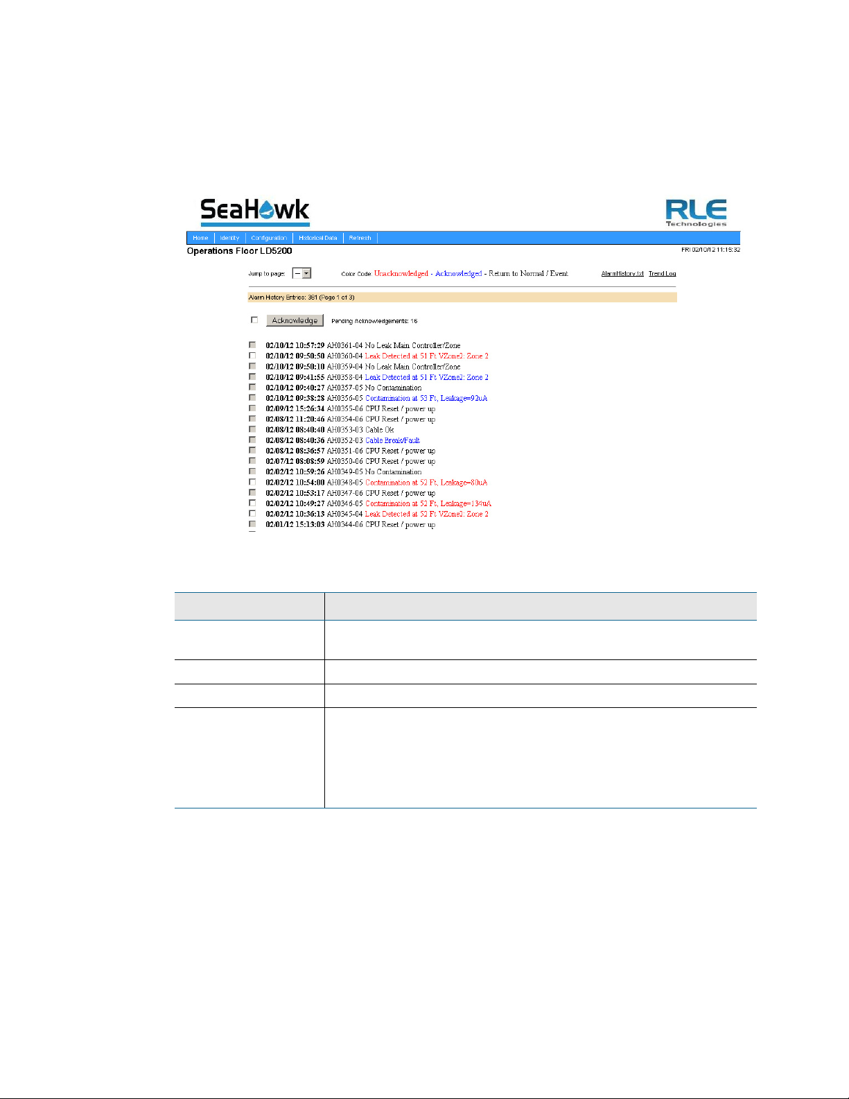
4 Web Interface
4.4 Historical Data
The Historical Data link provides access to logged historical data, including alarm and
trending data.The LD5200’s historical data includes a time-stamped chronology of events and
a trend log that contains occurrences of current leakage.
Figure 4.34
Option Description
Jump to Page Use this drop down menu to access additional pages of historical
AlarmHistory.txt Click this link to download a copy of the alarm history in a .txt format.
Trend Log View trend log data.
Acknowledge Each acknowledgeable alarm event has a checkbox in front of it.
Table 4.16
Historical Data Page
data.
Click individual checkboxes and press the Acknowledge button to
acknowledge selected alarms. If you wish to acknowledge all alarms
on the page, click the checkbox in front of the Acknowledge button
(this will activate all the available checkboxes) and click the
Acknowledge button.
Historical Data Options
Each entry in the alarm history is recorded in the following format:
82 LD5200 User Guide 800.518.1519
Page 83

4 Web Interface
checkbox MM/DD/YY HH:MM:SS. AHxxxx-yy
.
Item Description
checkbox
The selected alarm will be acknowledged once the Acknowledge
button is pressed. Only events with a white checkbox can be
checked and acknowledged. Gray checkboxes are inactive.
date and time
AH
xxxx
yy
Displayed as MM/DD/YY and HH:MM:SS (24 hour format)
Stands for “alarm history”
The log entry number for the alarm/event.
The event code, which indicates the type of event, as follows:
03 – Cable Fault
04 – Leak Detected
05 – Contamination Detected
06 – Reset/Power Up
text
Table 4.17
Alarm History Log Description
Provides details about the current alarm/event.
Alarm history data is also available as a text file (.txt.). Click the AlarmHistory.txt link to
download the data as a text file.
Figure 4.35
rletech.com LD5200 User Guide 83
Alarm History Text File (.txt)
Page 84

4 Web Interface
The Trend Log option provides a trending list of logged current leakage. This data provides
assistance in troubleshooting leaks and inaccurate readings. Click the Trend Log link to access
this information.
Figure 4.36
Trend Log
4.5 Refresh
Click the Refresh link to manually check for status updates. The LD5200 will refresh all its
data, and poll all connected devices for their most recent data. The Refresh link is especially
helpful if the system’s refresh rate is set at a long interval, or when new equipment is
connected to the system. Instead of waiting for the LD5200 to refresh on its own, click the link
to force a system refresh.
To adjust the automatic refresh rate, refer to Figure 4.12, “Web Configuration Page” on
page 59.
84 LD5200 User Guide 800.518.1519
Page 85

CHAPTER 0MODBUS COMMUNICATION
5.1 Comm Port Settings
The Modbus/EIA-485 Configuration Menu allows users to configure all three of the LD5200’s
EIA-485 Modbus ports. The LD5200 is configurable as a both a Modbus master and a Modbus
slave device. As a slave device, the LD5200 can have only one master. All three ports may
have their addresses and baud rates set in this menu. All addresses may be different and can be
configured from 0 (disabled) to 254. Baud rates can be different and can be configured as 9600
(default), 19200, or 38400. Settings can be configured through both the LCD and the web
interface.
C HAPTER
The Leak Detection Master option enables slave units to activate the LD5200 when they are
triggered into an alarm state. This function is beneficial when the LD5200 is a remote system
that does not have personnel in the immediate vicinity to monitor the alarm status.
When using the leak detection master option, the LD5200 relays can be activated according to
the slave unit alarm. If the slave has a leak alarm or a cable break alarm, the LD5200 leak or
cable relay will change state, respectively (i.e. it will trigger that an alarm is present). The zone
will then appear on the LCD and an alarm state will be reported to the top level of the system.
5.2 Leak Detection Modbus Master
This feature allows the LD5200 to act as a Modbus master, so it can talk to other RLE distance
read panels. The system status can be viewed by using the view zones menu. The LD5200 will
display leak, cable break, cable contamination, and loss of communications alarms from the
slave units connected to it.
5.2.1 Connect Distance Read Panels to the LD5200
Using a two wire configuration, connect the slave units in a 485 daisy chain. You will have to
set the EIA-485 slave address in each Leak detection unit. The first unit connected must be set
to address 2. The following units will increase in numeric order by one unit (e.g., the next unit
would be set to address 3, the following would be set to address 4, etc.; see Figure 5.1.)
rletech.com LD5200 User Guide 85
Page 86

5 Modbus Communication
Figure 5.1
LD5200 Connection Diagram
5.3 Implementation Basics
The LD5200 is capable of communicating via the half-duplex EIA-485 serial communication
standard. The EIA-485 medium allows for multiple devices on a multi-drop network.
5.3.1 Modes of Transmission
The Modbus protocol uses ASCII and RTU modes of transmission. The LD5200 supports only
the RTU mode of transmission, with 8 data bits, no parity and one stop bit. Every Modbus
packet consists of four fields:
♦ Slave Address Field
♦ Function Field
♦ Data Field
♦ Error Check Field (Checksum)
5.3.1.1 Slave Address Field
The slave address field is set by the going into local 160x160 display on the front panel. Go to
COMM PORT SETTINGS from the Main Menu screen. Select the Modbus Slave address and
the baud rate to be used for either/or EIA-485 Port1 and EIA-485 Port2.
5.3.1.2 Function Field
The function field is one byte in length and tells the LD5200 which function to perform. The
supported functions are 03 (Read 4xxxx output registers), 04 (Read 3xxxx input registers), 06
(Preset single register) and 16 (Preset multiple registers).
5.3.1.3 Data Field
The data field of the request is a variable length depending on the function. The data fields for
the LD5200 are 16-bit registers, transmitted high order byte first (big-endian).
86 LD5200 User Guide 800.518.1519
Page 87
5 Modbus Communication
5.3.1.4 Error Check (Checksum) Field
The checksum field lets the receiving device determine if the packet has transmission errors.
The LD5200 RTU mode uses a 16-bit cyclic redundancy check (CRC-16).
Exception Responses
If a Modbus master sends an invalid command to the LD5200 or attempts to read an invalid
register, an exception response is generated. The response packet will have the high order bit
of the function code set to one. The data field of the exception response contains the exception
error code.
Code Name Description
01 Illegal Function The function code is not supported
02 Illegal Data Address Attempt to access an invalid address
03 Illegal Data Value Attempt to set a variable to an invalid value
Table 5.1
Exception Codes
5.4 Packet Communications For The LD5200
This section covers the registers, their names, and a brief description of what they refer to.
5.4.1 Function 03: Read Output Registers
To read the LD5200 parameter values, the master must send a Read Output Registers request
packet. The Read Output Registers request packet specifies a start register and the number of
registers to read. The start register is numbered from zero (40001 = zero, 40002 = one, etc).
Read Registers Request Packet Read Registers Response Packet
Slave Address (1 byte) Slave Address (1 byte)
03 (Function code) (1 byte) 03 (Function code) (1 byte)
Start Register (2 bytes) Byte count (1 byte)
# of registers to read (2 bytes) First register (2 bytes)
Crc Checksum (2 bytes) Second register (2 bytes)
…
Crc Checksum (2 bytes)
Table 5.2
Read Output Registers Packet Structure
rletech.com LD5200 User Guide 87
Page 88

5 Modbus Communication
Register Name Description Units Range
40001 Leak Threshold Trip current for leak alarm 25-295
0-65535
uAmps
40002 Contamination
Threshold
Trip current for contamination alarm 20-295
uAmps
0-65535
40003 Spare 0-65535
40004 Spare 0-65535
40005 Spare 0-65535
40006 Spare 0-65535
40007 Spare 0-65535
40008 Spare 0-65535
40009 Spare 0-65535
40010 Spare 0-65535
40011 Spare 0-65535
40012 Spare 0-65535
40013 Spare 0-65535
40014 Spare 0-65535
40015 Spare 0-65535
40016 Leak Alarm Delay Leak Alarm Delay 5-995
0-65535
seconds
40017 Contamination Alarm
Delay
Table 5.3
Output Registers
Contamination Alarm Delay 5-995
seconds
0-65535
88 LD5200 User Guide 800.518.1519
Page 89

5.4.2 Function 04: Read Input Registers
To read the LD5200 input values, the master must send a Read Input Registers request packet.
The Read Input Registers request packet specifies a start register and the number of registers
to read. The start register is numbered from zero (30001 = zero, 30002 = one, etc).
Read Registers Request Packet Read Registers Response Packet
Slave Address (1 byte) Slave Address (1 byte)
04 (Function code) (1 byte) 04 (Function code) (1 byte)
Start Register (2 bytes) Byte count (1 byte)
# of registers to read (2 bytes) First register (2 bytes)
Crc Checksum (2 bytes) Second register (2 bytes)
…
Crc Checksum (2 bytes)
Table 5.4
Read Input Registers Packet Structure
5 Modbus Communication
rletech.com LD5200 User Guide 89
Page 90

5 Modbus Communication
Register Name Description Units Range
30001 Status Bit level status
None 0-65535
00 : 1 = Leak is Detected
01 : 1 = Cable Break Alarm
02 : 1 = Contamination is
Detected
03-15 : Spare
30002 Leak Distance Location of leak Ft/Meters 0-65535
30003 Units Unit of measure 1=Ft
0-65535
0=Meters
30004 Leak Current Leakage current on cable uAmps 0-65535
30005 Cable Length Installed cable length Ft/Meters 0-65535
30006 Loop1 Resistance Resistance of cable Ohms 0-65535
30007 Loop2 Resistance Resistance of cable Ohms 0-65535
30008 Resistance per Foot Resistance of cable Ohms x1000 0-65535
30009 Firmware Version Firmware version xx.xx X 100 0-65535
30010 Virtual Zone Alarm Status
(00=Zone1...15=Zone16)
30011 Virtual Zone Alarm Status
(00=Zone17...15=Zone32)
Bit Level Status
Zone 1 through Zone 16
Bit Level Status
Zone 17 through Zone 32
None 0-65535
None 0-65535
38001 Leak Location Float Value Location of leak in meters
Meters 0-65535
(float-MSW)
38002 Leak Location Float Value Location of leak in meters
Meters 0-65535
(float-LSW)
30012 Modbus Zone Enabled Flags
(00=Modbus Zone 2...
15=Modbus Zone 16)
Bit Level Status
Modbus Zone 2 through
Modbus Zone 16
None 0-65535
30013 Modbus Zone2 Status Bit Level Status None 0-65535
30014 Modbus Zone2 Distance Location of leak Ft/Meters 0-65535
30015 Modbus Zone3 Status Bit Level Status None 0-65535
30016 Modbus Zone3 Distance Location of leak Ft/Meters 0-65535
30017 Modbus Zone4 Status Bit Level Status None 0-65535
30018 Modbus Zone4 Distance Location of leak Ft/Meters 0-65535
30019 Modbus Zone5 Status Bit Level Status None 0-65535
30020 Modbus Zone5 Distance Location of leak Ft/Meters 0-65535
30021 Modbus Zone6 Status Bit Level Status None 0-65535
30022 Modbus Zone6 Distance Location of leak Ft/Meters 0-65535
30023 Modbus Zone7 Status Bit Level Status None 0-65535
Table 5.5
Input Registers
90 LD5200 User Guide 800.518.1519
Page 91

5 Modbus Communication
Register Name Description Units Range
30024 Modbus Zone7 Distance Location of leak Ft/Meters 0-65535
30025 Modbus Zone8 Status Bit Level Status None 0-65535
30026 Modbus Zone8 Distance Location of leak Ft/Meters 0-65535
30027 Modbus Zone9 Status Bit Level Status None 0-65535
30028 Modbus Zone9 Distance Location of leak Ft/Meters 0-65535
30029 Modbus Zone10 Status Bit Level Status None 0-65535
30030 Modbus Zone10 Distance Location of leak Ft/Meters 0-65535
30031 Modbus Zone11 Status Bit Level Status None 0-65535
30032 Modbus Zone11 Distance Location of leak Ft/Meters 0-65535
30033 Modbus Zone12 Status Bit Level Status None 0-65535
30034 Modbus Zone12 Distance Location of leak Ft/Meters 0-65535
30035 Modbus Zone13 Status Bit Level Status None 0-65535
30036 Modbus Zone13 Distance Location of leak Ft/Meters 0-65535
30037 Modbus Zone14 Status Bit Level Status None 0-65535
30038 Modbus Zone14 Distance Location of leak Ft/Meters 0-65535
30039 Modbus Zone15 Status Bit Level Status None 0-65535
30040 Modbus Zone15 Distance Location of leak Ft/Meters 0-65535
30041 Modbus Zone16 Status Bit Level Status None 0-65535
30042 Modbus Zone16 Distance Location of leak Ft/Meters 0-65535
30043 Modbus Zone Enabled Flags
(00=Modbus Zone 17...
15=Modbus Zone 32)
Bit Level Status
Modbus Zone 17 through
Modbus Zone 32
None 0-65535
30044 Modbus Zone17 Status Bit Level Status None 0-65535
30045 Modbus Zone17 Distance Location of leak Ft/Meters 0-65535
30046 Modbus Zone18 Status Bit Level Status None 0-65535
30047 Modbus Zone18 Distance Location of leak Ft/Meters 0-65535
30048 Modbus Zone19 Status Bit Level Status None 0-65535
30049 Modbus Zone19 Distance Location of leak Ft/Meters 0-65535
30050 Modbus Zone20 Status Bit Level Status None 0-65535
30051 Modbus Zone20 Distance Location of leak Ft/Meters 0-65535
30052 Modbus Zone21 Status Bit Level Status None 0-65535
30053 Modbus Zone21 Distance Location of leak Ft/Meters 0-65535
30054 Modbus Zone22 Status Bit Level Status None 0-65535
30055 Modbus Zone22 Distance Location of leak Ft/Meters 0-65535
30056 Modbus Zone23 Status Bit Level Status None 0-65535
30057 Modbus Zone23 Distance Location of leak Ft/Meters 0-65535
30058 Modbus Zone24 Status Bit Level Status None 0-65535
Table 5.5
rletech.com LD5200 User Guide 91
Input Registers (continued)
Page 92

5 Modbus Communication
Register Name Description Units Range
30059 Modbus Zone24 Distance Location of leak Ft/Meters 0-65535
30060 Modbus Zone25 Status Bit Level Status None 0-65535
30061 Modbus Zone25 Distance Location of leak Ft/Meters 0-65535
30062 Modbus Zone26 Status Bit Level Status None 0-65535
30063 Modbus Zone26 Distance Location of leak Ft/Meters 0-65535
30064 Modbus Zone27 Status Bit Level Status None 0-65535
30065 Modbus Zone27 Distance Location of leak Ft/Meters 0-65535
30066 Modbus Zone28 Status Bit Level Status None 0-65535
30067 Modbus Zone28 Distance Location of leak Ft/Meters 0-65535
30068 Modbus Zone29 Status Bit Level Status None 0-65535
30069 Modbus Zone29 Distance Location of leak Ft/Meters 0-65535
30070 Modbus Zone30 Status Bit Level Status None 0-65535
30071 Modbus Zone30 Distance Location of leak Ft/Meters 0-65535
30072 Modbus Zone31 Status Bit Level Status None 0-65535
30073 Modbus Zone31 Distance Location of leak Ft/Meters 0-65535
30074 Modbus Zone32 Status Bit Level Status None 0-65535
30075 Modbus Zone32 Distance Location of leak Ft/Meters 0-65535
30076 Modbus Zone Enabled Flags
(00=Modbus Zone 33...
15=Modbus Zone 48)
Bit Level Status
Modbus Zone 33 through
Modbus Zone 48
None 0-65535
30077 Modbus Zone33 Status Bit Level Status None 0-65535
30078 Modbus Zone33 Distance Location of leak Ft/Meters 0-65535
30079 Modbus Zone34 Status Bit Level Status None 0-65535
30080 Modbus Zone34 Distance Location of leak Ft/Meters 0-65535
30081 Modbus Zone35 Status Bit Level Status None 0-65535
30082 Modbus Zone35 Distance Location of leak Ft/Meters 0-65535
30083 Modbus Zone36 Status Bit Level Status None 0-65535
30084 Modbus Zone36 Distance Location of leak Ft/Meters 0-65535
30085 Modbus Zone37 Status Bit Level Status None 0-65535
30086 Modbus Zone37 Distance Location of leak Ft/Meters 0-65535
30087 Modbus Zone38 Status Bit Level Status None 0-65535
30088 Modbus Zone38 Distance Location of leak Ft/Meters 0-65535
30089 Modbus Zone39 Status Bit Level Status None 0-65535
30090 Modbus Zone39 Distance Location of leak Ft/Meters 0-65535
30091 Modbus Zone40 Status Bit Level Status None 0-65535
30092 Modbus Zone40 Distance Location of leak Ft/Meters 0-65535
30093 Modbus Zone41 Status Bit Level Status None 0-65535
Table 5.5
92 LD5200 User Guide 800.518.1519
Input Registers (continued)
Page 93

5 Modbus Communication
Register Name Description Units Range
30094 Modbus Zone41 Distance Location of leak Ft/Meters 0-65535
30095 Modbus Zone42 Status Bit Level Status None 0-65535
30096 Modbus Zone42 Distance Location of leak Ft/Meters 0-65535
30097 Modbus Zone43 Status Bit Level Status None 0-65535
30098 Modbus Zone43 Distance Location of leak Ft/Meters 0-65535
30099 Modbus Zone44 Status Bit Level Status None 0-65535
30100 Modbus Zone44 Distance Location of leak Ft/Meters 0-65535
30101 Modbus Zone45 Status Bit Level Status None 0-65535
30102 Modbus Zone45 Distance Location of leak Ft/Meters 0-65535
30103 Modbus Zone46 Status Bit Level Status None 0-65535
30104 Modbus Zone46 Distance Location of leak Ft/Meters 0-65535
30105 Modbus Zone47 Status Bit Level Status None 0-65535
30106 Modbus Zone47 Distance Location of leak Ft/Meters 0-65535
30107 Modbus Zone48 Status Bit Level Status None 0-65535
30108 Modbus Zone48 Distance Location of leak Ft/Meters 0-65535
30109 Modbus Zone Enabled Flags
(00=Modbus Zone 49...
15=Modbus Zone 64)
Bit Level Status
Modbus Zone 49 through
Modbus Zone 64
None 0-65535
30110 Modbus Zone49 Status Bit Level Status None 0-65535
30111 Modbus Zone49 Distance Location of leak Ft/Meters 0-65535
30112 Modbus Zone50 Status Bit Level Status None 0-65535
30113 Modbus Zone50 Distance Location of leak Ft/Meters 0-65535
30114 Modbus Zone51 Status Bit Level Status None 0-65535
30115 Modbus Zone51 Distance Location of leak Ft/Meters 0-65535
30116 Modbus Zone52 Status Bit Level Status None 0-65535
30117 Modbus Zone52 Distance Location of leak Ft/Meters 0-65535
30118 Modbus Zone53 Status Bit Level Status None 0-65535
30119 Modbus Zone53 Distance Location of leak Ft/Meters 0-65535
30120 Modbus Zone54 Status Bit Level Status None 0-65535
30121 Modbus Zone54 Distance Location of leak Ft/Meters 0-65535
30122 Modbus Zone55 Status Bit Level Status None 0-65535
30123 Modbus Zone55 Distance Location of leak Ft/Meters 0-65535
30124 Modbus Zone56 Status Bit Level Status None 0-65535
30125 Modbus Zone56 Distance Location of leak Ft/Meters 0-65535
30126 Modbus Zone57 Status Bit Level Status None 0-65535
30127 Modbus Zone57 Distance Location of leak Ft/Meters 0-65535
30128 Modbus Zone58 Status Bit Level Status None 0-65535
Table 5.5
rletech.com LD5200 User Guide 93
Input Registers (continued)
Page 94

5 Modbus Communication
Register Name Description Units Range
30129 Modbus Zone58 Distance Location of leak Ft/Meters 0-65535
30130 Modbus Zone59 Status Bit Level Status None 0-65535
30131 Modbus Zone59 Distance Location of leak Ft/Meters 0-65535
30132 Modbus Zone60 Status Bit Level Status None 0-65535
30133 Modbus Zone60 Distance Location of leak Ft/Meters 0-65535
30134 Modbus Zone61 Status Bit Level Status None 0-65535
30135 Modbus Zone61 Distance Location of leak Ft/Meters 0-65535
30136 Modbus Zone62 Status Bit Level Status None 0-65535
30137 Modbus Zone62 Distance Location of leak Ft/Meters 0-65535
30138 Modbus Zone63 Status Bit Level Status None 0-65535
30139 Modbus Zone63 Distance Location of leak Ft/Meters 0-65535
30140 Modbus Zone64 Status Bit Level Status None 0-65535
30141 Modbus Zone64 Distance Location of leak Ft/Meters 0-65535
30142 Modbus Zone Enabled Flags
(00=Modbus Zone 65...
15=Modbus Zone 80)
Bit Level Status
Modbus Zone 65 through
Modbus Zone 80
None 0-65535
30143 Modbus Zone65 Status Bit Level Status None 0-65535
30144 Modbus Zone65 Distance Location of leak Ft/Meters 0-65535
30145 Modbus Zone66 Status Bit Level Status None 0-65535
30146 Modbus Zone66 Distance Location of leak Ft/Meters 0-65535
30147 Modbus Zone67 Status Bit Level Status None 0-65535
30148 Modbus Zone67 Distance Location of leak Ft/Meters 0-65535
30149 Modbus Zone68 Status Bit Level Status None 0-65535
30150 Modbus Zone68 Distance Location of leak Ft/Meters 0-65535
30151 Modbus Zone69 Status Bit Level Status None 0-65535
30152 Modbus Zone69 Distance Location of leak Ft/Meters 0-65535
30153 Modbus Zone70 Status Bit Level Status None 0-65535
30154 Modbus Zone70 Distance Location of leak Ft/Meters 0-65535
30155 Modbus Zone71 Status Bit Level Status None 0-65535
30156 Modbus Zone71 Distance Location of leak Ft/Meters 0-65535
30157 Modbus Zone72 Status Bit Level Status None 0-65535
30158 Modbus Zone72 Distance Location of leak Ft/Meters 0-65535
30159 Modbus Zone73 Status Bit Level Status None 0-65535
30160 Modbus Zone73 Distance Location of leak Ft/Meters 0-65535
30161 Modbus Zone74 Status Bit Level Status None 0-65535
30162 Modbus Zone74 Distance Location of leak Ft/Meters 0-65535
30163 Modbus Zone75 Status Bit Level Status None 0-65535
Table 5.5
94 LD5200 User Guide 800.518.1519
Input Registers (continued)
Page 95

5 Modbus Communication
Register Name Description Units Range
30164 Modbus Zone75 Distance Location of leak Ft/Meters 0-65535
30165 Modbus Zone76 Status Bit Level Status None 0-65535
30166 Modbus Zone76 Distance Location of leak Ft/Meters 0-65535
30167 Modbus Zone77 Status Bit Level Status None 0-65535
30168 Modbus Zone77 Distance Location of leak Ft/Meters 0-65535
30169 Modbus Zone78 Status Bit Level Status None 0-65535
30170 Modbus Zone78 Distance Location of leak Ft/Meters 0-65535
30171 Modbus Zone79 Status Bit Level Status None 0-65535
30172 Modbus Zone79 Distance Location of leak Ft/Meters 0-65535
30173 Modbus Zone80 Status Bit Level Status None 0-65535
30174 Modbus Zone80 Distance Location of leak Ft/Meters 0-65535
30175 Modbus Zone Enabled Flags
(00=Modbus Zone 81...
15=Modbus Zone 96)
Bit Level Status
Modbus Zone 81 through
Modbus Zone 96
None 0-65535
30176 Modbus Zone81 Status Bit Level Status None 0-65535
30177 Modbus Zone81Distance Location of leak Ft/Meters 0-65535
30178 Modbus Zone82 Status Bit Level Status None 0-65535
30179 Modbus Zone82 Distance Location of leak Ft/Meters 0-65535
30180 Modbus Zone83 Status Bit Level Status None 0-65535
30181 Modbus Zone83 Distance Location of leak Ft/Meters 0-65535
30182 Modbus Zone84 Status Bit Level Status None 0-65535
30183 Modbus Zone84 Distance Location of leak Ft/Meters 0-65535
30184 Modbus Zone85 Status Bit Level Status None 0-65535
30185 Modbus Zone85 Distance Location of leak Ft/Meters 0-65535
30186 Modbus Zone86 Status Bit Level Status None 0-65535
30187 Modbus Zone86 Distance Location of leak Ft/Meters 0-65535
30188 Modbus Zone87 Status Bit Level Status None 0-65535
30189 Modbus Zone87 Distance Location of leak Ft/Meters 0-65535
30190 Modbus Zone88 Status Bit Level Status None 0-65535
30191 Modbus Zone88 Distance Location of leak Ft/Meters 0-65535
30192 Modbus Zone89 Status Bit Level Status None 0-65535
30193 Modbus Zone89 Distance Location of leak Ft/Meters 0-65535
30194 Modbus Zone90 Status Bit Level Status None 0-65535
30195 Modbus Zone90 Distance Location of leak Ft/Meters 0-65535
30196 Modbus Zone91 Status Bit Level Status None 0-65535
30197 Modbus Zone91 Distance Location of leak Ft/Meters 0-65535
30198 Modbus Zone92 Status Bit Level Status None 0-65535
Table 5.5
rletech.com LD5200 User Guide 95
Input Registers (continued)
Page 96

5 Modbus Communication
Register Name Description Units Range
30199 Modbus Zone92 Distance Location of leak Ft/Meters 0-65535
30200 Modbus Zone93 Status Bit Level Status None 0-65535
30201 Modbus Zone93 Distance Location of leak Ft/Meters 0-65535
30202 Modbus Zone94 Status Bit Level Status None 0-65535
30203 Modbus Zone94 Distance Location of leak Ft/Meters 0-65535
30204 Modbus Zone95 Status Bit Level Status None 0-65535
30205 Modbus Zone95 Distance Location of leak Ft/Meters 0-65535
30206 Modbus Zone96 Status Bit Level Status None 0-65535
30207 Modbus Zone96 Distance Location of leak Ft/Meters 0-65535
30208 Modbus Zone Enabled Flags
(00=Modbus Zone 97...
15=Modbus Zone 112)
Bit Level Status
Modbus Zone 97 through
Modbus Zone 112
None 0-65535
30209 Modbus Zone97 Status Bit Level Status None 0-65535
30210 Modbus Zone97 Distance Location of leak Ft/Meters 0-65535
30211 Modbus Zone98 Status Bit Level Status None 0-65535
30212 Modbus Zone98 Distance Location of leak Ft/Meters 0-65535
30213 Modbus Zone99 Status Bit Level Status None 0-65535
30214 Modbus Zone99 Distance Location of leak Ft/Meters 0-65535
30215 Modbus Zone100 Status Bit Level Status None 0-65535
30216 Modbus Zone100 Distance Location of leak Ft/Meters 0-65535
30217 Modbus Zone101 Status Bit Level Status None 0-65535
30218 Modbus Zone101Distance Location of leak Ft/Meters 0-65535
30219 Modbus Zone102 Status Bit Level Status None 0-65535
30220 Modbus Zone102 Distance Location of leak Ft/Meters 0-65535
30221 Modbus Zone103 Status Bit Level Status None 0-65535
30222 Modbus Zone103 Distance Location of leak Ft/Meters 0-65535
30223 Modbus Zone104 Status Bit Level Status None 0-65535
30224 Modbus Zone104 Distance Location of leak Ft/Meters 0-65535
30225 Modbus Zone105 Status Bit Level Status None 0-65535
30226 Modbus Zone105 Distance Location of leak Ft/Meters 0-65535
30227 Modbus Zone106 Status Bit Level Status None 0-65535
30228 Modbus Zone106 Distance Location of leak Ft/Meters 0-65535
30229 Modbus Zone107 Status Bit Level Status None 0-65535
30230 Modbus Zone107 Distance Location of leak Ft/Meters 0-65535
30231 Modbus Zone108 Status Bit Level Status None 0-65535
30232 Modbus Zone108Distance Location of leak Ft/Meters 0-65535
30233 Modbus Zone109 Status Bit Level Status None 0-65535
Table 5.5
96 LD5200 User Guide 800.518.1519
Input Registers (continued)
Page 97

5 Modbus Communication
Register Name Description Units Range
30234 Modbus Zone109 Distance Location of leak Ft/Meters 0-65535
30235 Modbus Zone110 Status Bit Level Status None 0-65535
30236 Modbus Zone110 Distance Location of leak Ft/Meters 0-65535
30237 Modbus Zone111 Status Bit Level Status None 0-65535
30238 Modbus Zone111 Distance Location of leak Ft/Meters 0-65535
30239 Modbus Zone112 Status Bit Level Status None 0-65535
30240 Modbus Zone112 Distance Location of leak Ft/Meters 0-65535
30241 Modbus Zone Enabled Flags
(00=Modbus Zone113...
15=Modbus Zone 128)
Bit Level Status
Modbus Zone 113 through
Modbus Zone 128
None 0-65535
30242 Modbus Zone113 Status Bit Level Status None 0-65535
30243 Modbus Zone113 Distance Location of leak Ft/Meters 0-65535
30244 Modbus Zone114 Status Bit Level Status None 0-65535
30245 Modbus Zone114 Distance Location of leak Ft/Meters 0-65535
30246 Modbus Zone115 Status Bit Level Status None 0-65535
30247 Modbus Zone115 Distance Location of leak Ft/Meters 0-65535
30248 Modbus Zone116 Status Bit Level Status None 0-65535
30249 Modbus Zone116 Distance Location of leak Ft/Meters 0-65535
30250 Modbus Zone117 Status Bit Level Status None 0-65535
30251 Modbus Zone117 Distance Location of leak Ft/Meters 0-65535
30252 Modbus Zone118 Status Bit Level Status None 0-65535
30253 Modbus Zone118 Distance Location of leak Ft/Meters 0-65535
30254 Modbus Zone119 Status Bit Level Status None 0-65535
30255 Modbus Zone119 Distance Location of leak Ft/Meters 0-65535
30256 Modbus Zone120 Status Bit Level Status None 0-65535
30257 Modbus Zone120 Distance Location of leak Ft/Meters 0-65535
30258 Modbus Zone121 Status Bit Level Status None 0-65535
30259 Modbus Zone121 Distance Location of leak Ft/Meters 0-65535
30260 Modbus Zone122 Status Bit Level Status None 0-65535
30261 Modbus Zone122 Distance Location of leak Ft/Meters 0-65535
30262 Modbus Zone123 Status Bit Level Status None 0-65535
30263 Modbus Zone123 Distance Location of leak Ft/Meters 0-65535
30264 Modbus Zone124 Status Bit Level Status None 0-65535
30265 Modbus Zone124 Distance Location of leak Ft/Meters 0-65535
30266 Modbus Zone125 Status Bit Level Status None 0-65535
30267 Modbus Zone125 Distance Location of leak Ft/Meters 0-65535
30268 Modbus Zone126 Status Bit Level Status None 0-65535
Table 5.5
rletech.com LD5200 User Guide 97
Input Registers (continued)
Page 98

5 Modbus Communication
Register Name Description Units Range
30269 Modbus Zone126 Distance Location of leak Ft/Meters 0-65535
30270 Modbus Zone127 Status Bit Level Status None 0-65535
30271 Modbus Zone127 Distance Location of leak Ft/Meters 0-65535
30272 Modbus Zone128 Status Bit Level Status None 0-65535
30273 Modbus Zone128 Distance Location of leak Ft/Meters 0-65535
Table 5.5
Input Registers (continued)
Status Flags
Register 30010 Register 30011
Bit Description Bit Description
00 1 = Zone1 00 1 = Zone17
01 1 = Zone2 01 1 = Zone18
02 1 = Zone3 02 1 = Zone19
03 1 = Zone4 03 1 = Zone20
04 1 = Zone5 04 1 = Zone21
05 1 = Zone6 05 1 = Zone22
06 1 = Zone7 06 1 = Zone23
07 1 = Zone8 07 1 = Zone24
08 1 = Zone9 08 1 = Zone25
09 1 = Zone10 09 1 = Zone26
10 1 = Zone11 10 1 = Zone27
11 1 = Zone12 11 1 = Zone28
12 1 = Zone13 12 1 = Zone29
13 1 = Zone14 13 1 = Zone30
14 1 = Zone15 14 1 = Zone31
15 1 = Zone16 15 1 = Zone32
Table 5.6
Status Flags (Registers 30010 and 30011)
Bit Description
00 1= Leak Detected
01 1 = Cable Break
02 1 = Contamination
07 1 = Communication Loss
Table 5.7
98 LD5200 User Guide 800.518.1519
Status Flags (Register 30013 - 30273)
Page 99
5.4.3 Function 06: Preset Single Register
To set the LD5200 parameter value, the master must send a Preset Single Register request
packet. The Preset Single Register request packet specifies a register and the data to write to
that register. The register is numbered from zero (40001 = zero, 40002 = one, etc).
Preset Register Request Packet Preset Register Response Packet
Slave Address (1 byte) Slave Address (1 byte)
06 (Function code) (1 byte) 06 (Function code) (1 byte)
Register (2 bytes) Register (2 byte)
Data (2 bytes) Data (2 bytes)
Crc Checksum (2 bytes) Crc Checksum (2 bytes)
Table 5.8
Preset Single Register Packet Structure
5.4.4 Function 16: Preset Multiple Registers
5 Modbus Communication
To set multiple LD5200 parameter values, the master must send a Preset Multiple Registers
request packet. The Preset Multiple Register request packet specifies a starting register, the
number of registers, a byte count and the data to write to the registers. The register is
numbered from zero (40001 = zero, 40002 = one, etc).
Preset Registers Request Packet Preset Registers Response Packet
Slave Address (1 byte) Slave Address (1 byte)
16 (Function code) (1 byte) 16 (Function code) (1 byte)
Start Register (2 bytes) Start Register (2 bytes)
# of registers to write (2 bytes) # of registers (2 bytes)
Byte Count (1 byte) Crc Checksum (2 bytes)
Data (2 bytes)
…
…
Crc Checksum (2 bytes)
Table 5.9
Preset Multiple Registers Packet Structure
rletech.com LD5200 User Guide 99
Page 100

5 Modbus Communication
5.5 RTU Framing
The example below shows a typical Query/Response from the LD5200 module.
Numbers
Slave
Address
02 04 00 00 00 03 B5 A3
Table 5.10
Function
Code
Query Sample
Starting
Register
“Msb”
Starting
Register
“Lsb”
of
Registers
“Lsb”
Number of
Registers
“Lsb”
CRC 16
“Lsb”
CRC
“Msb”
Slave
Address
02 04 06 00 00 00 00 00 01 B5 A3
Table 5.11
Function
Code
Response Sample
Count
Bytes of
Data
Register
Data
Msb Lsb
Register
Data
Msb Lsb
Register
Data
Msb Lsb
CRC 16
“Lsb”
Slave address 2 responds to Function Code 4 with 6 bytes of hexadecimal data and ends with
CRC16 checksum
Register Values:
40001 = 0000 (hex)
40002 = 0000 (hex)
40003 = 0001 (hex)
CRC 16
“Msb”
100 LD5200 User Guide 800.518.1519
 Loading...