

Page 1
Leak Detection
LD5100
User Guide
Page 2

Copyright and Trademark Notices
© Raymond & Lae Engineering, Inc. 2011. All rights reserved. RLE® is a registered trademark and
Seahawk™, Falcon™, and Raptor™ are trademarks of Raymond & Lae Engineering, Inc. The
products sold by Raymond & Lae Engineering, Inc. are subject to the limited warranty, limited liability,
and other terms and conditions of sale set forth at http://rletech.com/RLE-Terms-and-Conditions.html..
Revision History
Rev. No. Date
3.0 June 2010
3.1 February 2011
Note: As necessary, blank pages are added to make the page count even.
rletech.com 2 970.484.6510
Page 3

Product Registration
Product registration helps RLE Technologies inform owners of:
• Product upgrades
• Firmware enhancements
• New products and technologies
• Special offers available only to registered users
Submit registration information on the Support/Product Registration webpage at www.rletech.com.
Any information provided to RLE Technologies through the registration form will be regarded as
confidential. RLE will not sell or distribute any of the information to third parties. To read our Privacy
Policy, please visit our website: www.rletech.com.
Technical Support
Personal assistance is available Monday through Friday, from 8:00 a.m. to 5:00 p.m. MST.
For more information, please download the Product User Guide located on the Products/LD5100
section on our website at www.rletech.com.
A request for assistance may be sent to support@rletech.com.
Otherwise, please call us directly at: (970) 484-6510, and press “2” for technical support.
The following information is located on the bottom of each LD5100 unit. Please have this information
available whenever a technical support call is placed:
Product Model Number
Product Serial Number
Product Manufacture Date
970.484.6510 3 rletech.com
Page 4

RLE Product Warranty
Seller warrants to the Ultimate Purchaser (the purchaser who buys for use and not for resale) that all
products furnished under this order and which are manufactured by Seller will conform to final
specifications, drawings, samples and other written descriptions approved in writing by Seller, and will be
free from defects in materials and workmanship. These warranties shall remain in effect for a period of
twelve (12) months after shipment. If the Seller installs the equipment or supplies technical direction of
installation by contract, said one year shall run from the completion of installation, provided installation is not
unreasonably delayed by Ultimate Purchaser. Parts replaced or repaired in the warranty period shall carry
the unexpired portion of the original warranty. A unit placed with the purchaser on consignment and then
later purchased will be warranted for twelve (12) months from the time the Seller receives notification of the
Purchaser's intent to purchase said consigned item. The foregoing is in its entirety is subject to the provision
that in no case will the total warranty period extend beyond 18 months from date Seller ships equipment
from point of manufacture.
Products are NOT life and safety certified. In no event shall the Seller be liable for loss, damage, or expense
directly or indirectly arising from the use of the units, or from any other cause, except as expressly stated in
this warranty. Seller makes no warranties, express or implied, including any warranty as to merchantability
or fitness for a particular purpose or use. Seller is not liable for and Purchaser waives any right of action it
has or may have against Seller for any consequential or special damages arising out of any breach of
warranty, and for any damages Purchaser may claim for damage to any property or injury or death to any
person arising out of its purchase or the use, operation, or maintenance of the product. Seller will not be
liable for any labor subcontracted or performed by Purchaser for preparation of warranted item for return to
Seller's factory or for preparation work for field repair or replacement. Invoicing of Seller for labor either
performed or subcontracted by Purchaser will not be considered as a liability by the Seller.
The liability of Seller hereunder is limited to replacing or repairing at Seller's factory or on the job site at
Seller's option, any part or parts which have been returned to the Seller and which are defective or do not
conform to such specifications, drawings or other written descriptions; provided that such part or parts are
returned by the Ultimate Purchaser within ninety (90) days after such defect is discovered. The Seller shall
have the sole right to determine if the parts are to be repaired at the job site or whether they are to be
returned to the factory for repair or replacement. All items returned to Seller for repair or replacement must
be sent freight, prepaid to its factory. Purchaser must obtain Seller's Return Goods Authorization prior to
returning items. The above conditions must be met if warranty is to be valid. Seller will not be liable for any
damage done by unauthorized repair work, unauthorized replacement parts, from any misapplication of the
item, or for damage due to accident, abuse, or act of God.
This warranty shall be exclusive of any and all other warranties express or implied and may be modified only
by writing signed by any officer of the Seller. This warranty shall extend to the Ultimate Purchaser but to no
one else. Accessories supplied by Seller but manufactured by others carry any warranty the manufacturers
have made to Seller and which can be passed on to the Ultimate Purchaser.
Seller makes no warranty with respect to whether the products sold hereunder infringe any patent, U.S. or
foreign, and Purchaser represents that any specially ordered products do not infringe any patent. Purchaser
agrees to indemnify and hold Seller harmless from any liability by virtue of any patent claims where
Purchaser has ordered a product conforming to Purchaser's specifications, or conforming to Purchaser's
specific design.
Purchaser has not relied and shall not rely on any oral representation regarding the Product sold hereunder
and any oral representation shall not bind Seller and shall not be part of any warranty.
rletech.com 4 970.484.6510
Page 5

Contents
1 Product Overview . . . . . . . . . . . . . . . . . . . . . . . . . . . . . . . . . . . . . . . . . . . . . . . . . . . 15
Description . . . . . . . . . . . . . . . . . . . . . . . . . . . . . . . . . . . . . . . . . . . . . . . . . . . . . . . . . . . . . . . . . . . . . . 15
Operation . . . . . . . . . . . . . . . . . . . . . . . . . . . . . . . . . . . . . . . . . . . . . . . . . . . . . . . . . . . . . . . . . . . . . . . 15
Mechanical Description . . . . . . . . . . . . . . . . . . . . . . . . . . . . . . . . . . . . . . . . . . . . . . . . . . . . . . . . . . . . . 16
Installation . . . . . . . . . . . . . . . . . . . . . . . . . . . . . . . . . . . . . . . . . . . . . . . . . . . . . . . . . . . . . . . . . . . . . . . 16
Cable Reference Map . . . . . . . . . . . . . . . . . . . . . . . . . . . . . . . . . . . . . . . . . . . . . . . . . . . . . . . . . . . . . . 16
LCD User Interface . . . . . . . . . . . . . . . . . . . . . . . . . . . . . . . . . . . . . . . . . . . . . . . . . . . . . . . . . . . . . . . . 16
2 Connections and Settings . . . . . . . . . . . . . . . . . . . . . . . . . . . . . . . . . . . . . . . . . . . . 19
Main Board . . . . . . . . . . . . . . . . . . . . . . . . . . . . . . . . . . . . . . . . . . . . . . . . . . . . . . . . . . . . . . . . . . . . . . 20
SW1: Reset Switch . . . . . . . . . . . . . . . . . . . . . . . . . . . . . . . . . . . . . . . . . . . . . . . . . . . . . . . . . . . 20
SW2: Termination Setting . . . . . . . . . . . . . . . . . . . . . . . . . . . . . . . . . . . . . . . . . . . . . . . . . . . . . . 20
R39: Contrast . . . . . . . . . . . . . . . . . . . . . . . . . . . . . . . . . . . . . . . . . . . . . . . . . . . . . . . . . . . . . . . . 20
TB1: Input Power . . . . . . . . . . . . . . . . . . . . . . . . . . . . . . . . . . . . . . . . . . . . . . . . . . . . . . . . . . . . . 20
TB2 and TB3: RS485 Modbus Port 2 and 1. . . . . . . . . . . . . . . . . . . . . . . . . . . . . . . . . . . . . . . . . 20
TB4 & TB5: Relays. . . . . . . . . . . . . . . . . . . . . . . . . . . . . . . . . . . . . . . . . . . . . . . . . . . . . . . . . . . . 21
RS232 Connector. . . . . . . . . . . . . . . . . . . . . . . . . . . . . . . . . . . . . . . . . . . . . . . . . . . . . . . . . . . . . 21
TB6: 4-20mA Output . . . . . . . . . . . . . . . . . . . . . . . . . . . . . . . . . . . . . . . . . . . . . . . . . . . . . . . . . . 21
TB7: Cable Interface . . . . . . . . . . . . . . . . . . . . . . . . . . . . . . . . . . . . . . . . . . . . . . . . . . . . . . . . . . 22
AC Power Input . . . . . . . . . . . . . . . . . . . . . . . . . . . . . . . . . . . . . . . . . . . . . . . . . . . . . . . . . . . . . . 23
3 Installation . . . . . . . . . . . . . . . . . . . . . . . . . . . . . . . . . . . . . . . . . . . . . . . . . . . . . . . . .25
Installing the Unit. . . . . . . . . . . . . . . . . . . . . . . . . . . . . . . . . . . . . . . . . . . . . . . . . . . . . . . . . . . . . . . . . . 25
Connecting the SeaHawk Water Leak Detection Cable (SC) . . . . . . . . . . . . . . . . . . . . . . . . . . . . . . . . 25
Securing Cable to the Floor . . . . . . . . . . . . . . . . . . . . . . . . . . . . . . . . . . . . . . . . . . . . . . . . . . . . . 26
Apply Power to the Unit. . . . . . . . . . . . . . . . . . . . . . . . . . . . . . . . . . . . . . . . . . . . . . . . . . . . . . . . . . . . . 27
4 4-20mA Output Testing. . . . . . . . . . . . . . . . . . . . . . . . . . . . . . . . . . . . . . . . . . . . . . . 29
5 LCD Interface . . . . . . . . . . . . . . . . . . . . . . . . . . . . . . . . . . . . . . . . . . . . . . . . . . . . . . .31
Default/Idle Display . . . . . . . . . . . . . . . . . . . . . . . . . . . . . . . . . . . . . . . . . . . . . . . . . . . . . . . . . . . . . . . . 31
Main Menu . . . . . . . . . . . . . . . . . . . . . . . . . . . . . . . . . . . . . . . . . . . . . . . . . . . . . . . . . . . . . . . . . . . . . . 32
View Zones . . . . . . . . . . . . . . . . . . . . . . . . . . . . . . . . . . . . . . . . . . . . . . . . . . . . . . . . . . . . . . . . . . . . . . 33
Cable Status . . . . . . . . . . . . . . . . . . . . . . . . . . . . . . . . . . . . . . . . . . . . . . . . . . . . . . . . . . . . . . . . . . . . . 33
System Status . . . . . . . . . . . . . . . . . . . . . . . . . . . . . . . . . . . . . . . . . . . . . . . . . . . . . . . . . . . . . . . 33
Cable Length . . . . . . . . . . . . . . . . . . . . . . . . . . . . . . . . . . . . . . . . . . . . . . . . . . . . . . . . . . . . . . . . 34
Current . . . . . . . . . . . . . . . . . . . . . . . . . . . . . . . . . . . . . . . . . . . . . . . . . . . . . . . . . . . . . . . . . . . . . 34
Contamination Delay (ContamDly). . . . . . . . . . . . . . . . . . . . . . . . . . . . . . . . . . . . . . . . . . . . . . . . 34
Leak Delay (LeakDly). . . . . . . . . . . . . . . . . . . . . . . . . . . . . . . . . . . . . . . . . . . . . . . . . . . . . . . . . . 34
Leg 1 Resistance (Leg1 Res). . . . . . . . . . . . . . . . . . . . . . . . . . . . . . . . . . . . . . . . . . . . . . . . . . . . 34
Leg 2 Resistance (Leg2 Res). . . . . . . . . . . . . . . . . . . . . . . . . . . . . . . . . . . . . . . . . . . . . . . . . . . . 34
Cable Relay or Cable Test Relay. . . . . . . . . . . . . . . . . . . . . . . . . . . . . . . . . . . . . . . . . . . . . . . . . 34
Firmware Version . . . . . . . . . . . . . . . . . . . . . . . . . . . . . . . . . . . . . . . . . . . . . . . . . . . . . . . . . . . . . 34
Alarm History/Trend Log . . . . . . . . . . . . . . . . . . . . . . . . . . . . . . . . . . . . . . . . . . . . . . . . . . . . . . . . . . . . 35
Alarm History Log. . . . . . . . . . . . . . . . . . . . . . . . . . . . . . . . . . . . . . . . . . . . . . . . . . . . . . . . . . . . . 35
Trend Log. . . . . . . . . . . . . . . . . . . . . . . . . . . . . . . . . . . . . . . . . . . . . . . . . . . . . . . . . . . . . . . . . . . 35
Erase Alarm History . . . . . . . . . . . . . . . . . . . . . . . . . . . . . . . . . . . . . . . . . . . . . . . . . . . . . . . . . . . 35
rletech.com 5 970.484.6510
Page 6

Erase Trend log . . . . . . . . . . . . . . . . . . . . . . . . . . . . . . . . . . . . . . . . . . . . . . . . . . . . . . . . . . . . . . 35
Comm Port Status . . . . . . . . . . . . . . . . . . . . . . . . . . . . . . . . . . . . . . . . . . . . . . . . . . . . . . . . . . . . . . . . . 36
View Map . . . . . . . . . . . . . . . . . . . . . . . . . . . . . . . . . . . . . . . . . . . . . . . . . . . . . . . . . . . . . . . . . . . . . . . . 36
System Setup . . . . . . . . . . . . . . . . . . . . . . . . . . . . . . . . . . . . . . . . . . . . . . . . . . . . . . . . . . . . . . . . . . . . 36
Leak Trip Point . . . . . . . . . . . . . . . . . . . . . . . . . . . . . . . . . . . . . . . . . . . . . . . . . . . . . . . . . . . . . . . 37
Contamination Trip Point . . . . . . . . . . . . . . . . . . . . . . . . . . . . . . . . . . . . . . . . . . . . . . . . . . . . . . . 37
Leak Delay . . . . . . . . . . . . . . . . . . . . . . . . . . . . . . . . . . . . . . . . . . . . . . . . . . . . . . . . . . . . . . . . . . 37
Contamination Delay . . . . . . . . . . . . . . . . . . . . . . . . . . . . . . . . . . . . . . . . . . . . . . . . . . . . . . . . . . 37
Re-Alarm Delay . . . . . . . . . . . . . . . . . . . . . . . . . . . . . . . . . . . . . . . . . . . . . . . . . . . . . . . . . . . . . . 37
Latching Alarms . . . . . . . . . . . . . . . . . . . . . . . . . . . . . . . . . . . . . . . . . . . . . . . . . . . . . . . . . . . . . . 37
Supervised Relays . . . . . . . . . . . . . . . . . . . . . . . . . . . . . . . . . . . . . . . . . . . . . . . . . . . . . . . . . . . . 37
4-20MA Max Range . . . . . . . . . . . . . . . . . . . . . . . . . . . . . . . . . . . . . . . . . . . . . . . . . . . . . . . . . . . 37
Feet / Meters . . . . . . . . . . . . . . . . . . . . . . . . . . . . . . . . . . . . . . . . . . . . . . . . . . . . . . . . . . . . . . . . 37
Language . . . . . . . . . . . . . . . . . . . . . . . . . . . . . . . . . . . . . . . . . . . . . . . . . . . . . . . . . . . . . . . . . . . 38
Cable Test Relay . . . . . . . . . . . . . . . . . . . . . . . . . . . . . . . . . . . . . . . . . . . . . . . . . . . . . . . . . . . . . 38
Restore Defaults. . . . . . . . . . . . . . . . . . . . . . . . . . . . . . . . . . . . . . . . . . . . . . . . . . . . . . . . . . . . . . 38
Clock. . . . . . . . . . . . . . . . . . . . . . . . . . . . . . . . . . . . . . . . . . . . . . . . . . . . . . . . . . . . . . . . . . . . . . . 38
Resistance/Foot (Res/Ft) . . . . . . . . . . . . . . . . . . . . . . . . . . . . . . . . . . . . . . . . . . . . . . . . . . . . . . . 38
Zone Setup . . . . . . . . . . . . . . . . . . . . . . . . . . . . . . . . . . . . . . . . . . . . . . . . . . . . . . . . . . . . . . . . . . . . . . 39
Point Mapping . . . . . . . . . . . . . . . . . . . . . . . . . . . . . . . . . . . . . . . . . . . . . . . . . . . . . . . . . . . . . . . . . . . . 40
Comm Port Settings. . . . . . . . . . . . . . . . . . . . . . . . . . . . . . . . . . . . . . . . . . . . . . . . . . . . . . . . . . . . . . . . 40
6 Mapping the Cable . . . . . . . . . . . . . . . . . . . . . . . . . . . . . . . . . . . . . . . . . . . . . . . . . . 41
Mapping Directions . . . . . . . . . . . . . . . . . . . . . . . . . . . . . . . . . . . . . . . . . . . . . . . . . . . . . . . . . . . . . . . . 42
7 EIA-232 Interface . . . . . . . . . . . . . . . . . . . . . . . . . . . . . . . . . . . . . . . . . . . . . . . . . . . 43
Boot Up . . . . . . . . . . . . . . . . . . . . . . . . . . . . . . . . . . . . . . . . . . . . . . . . . . . . . . . . . . . . . . . . . . . . . . . . . 43
Main Menu . . . . . . . . . . . . . . . . . . . . . . . . . . . . . . . . . . . . . . . . . . . . . . . . . . . . . . . . . . . . . . . . . . . . . . . 44
SC – System Configuration . . . . . . . . . . . . . . . . . . . . . . . . . . . . . . . . . . . . . . . . . . . . . . . . . . . . . . . . . . 45
Modify LCD Password – 1 . . . . . . . . . . . . . . . . . . . . . . . . . . . . . . . . . . . . . . . . . . . . . . . . . . . . . . 45
Zone Setup – 2 . . . . . . . . . . . . . . . . . . . . . . . . . . . . . . . . . . . . . . . . . . . . . . . . . . . . . . . . . . . . . . . 45
Diagnostics – 3 . . . . . . . . . . . . . . . . . . . . . . . . . . . . . . . . . . . . . . . . . . . . . . . . . . . . . . . . . . . . . . . 46
Other Main Menu Functions . . . . . . . . . . . . . . . . . . . . . . . . . . . . . . . . . . . . . . . . . . . . . . . . . . . . . . . . . 47
8 Modbus Communication . . . . . . . . . . . . . . . . . . . . . . . . . . . . . . . . . . . . . . . . . . . . . 49
Implementation Basics. . . . . . . . . . . . . . . . . . . . . . . . . . . . . . . . . . . . . . . . . . . . . . . . . . . . . . . . . . . . . . 49
Modes of Transmission . . . . . . . . . . . . . . . . . . . . . . . . . . . . . . . . . . . . . . . . . . . . . . . . . . . . . . . . 49
Slave Address Field . . . . . . . . . . . . . . . . . . . . . . . . . . . . . . . . . . . . . . . . . . . . . . . . . . . . . . . . 49
Function Field. . . . . . . . . . . . . . . . . . . . . . . . . . . . . . . . . . . . . . . . . . . . . . . . . . . . . . . . . . . . . 50
Data Field. . . . . . . . . . . . . . . . . . . . . . . . . . . . . . . . . . . . . . . . . . . . . . . . . . . . . . . . . . . . . . . . 50
Error Check (Checksum) Field. . . . . . . . . . . . . . . . . . . . . . . . . . . . . . . . . . . . . . . . . . . . . . . . 50
Exception Responses. . . . . . . . . . . . . . . . . . . . . . . . . . . . . . . . . . . . . . . . . . . . . . . . . . . . . . . . . . 50
Packet Communications For The LD5100. . . . . . . . . . . . . . . . . . . . . . . . . . . . . . . . . . . . . . . . . . . . . . . 51
Function 03: Read Output Registers . . . . . . . . . . . . . . . . . . . . . . . . . . . . . . . . . . . . . . . . . . . . . . 51
Function 04: Read Input Registers . . . . . . . . . . . . . . . . . . . . . . . . . . . . . . . . . . . . . . . . . . . . . . . . 53
Function 06: Preset Single Register . . . . . . . . . . . . . . . . . . . . . . . . . . . . . . . . . . . . . . . . . . . . . . . 56
Function 16: Preset Multiple Registers . . . . . . . . . . . . . . . . . . . . . . . . . . . . . . . . . . . . . . . . . . . . . 57
RTU Framing . . . . . . . . . . . . . . . . . . . . . . . . . . . . . . . . . . . . . . . . . . . . . . . . . . . . . . . . . . . . . . . . . . . . . 58
A Updating Firmware . . . . . . . . . . . . . . . . . . . . . . . . . . . . . . . . . . . . . . . . . . . . . . . . . . 59
Updating the Flash Firmware. . . . . . . . . . . . . . . . . . . . . . . . . . . . . . . . . . . . . . . . . . . . . . . . . . . . . . . . . 59
B Leak Detection Modbus Master. . . . . . . . . . . . . . . . . . . . . . . . . . . . . . . . . . . . . . . . 61
Connecting Distance Read Panels to the LD5100 . . . . . . . . . . . . . . . . . . . . . . . . . . . . . . . . . . . . . . . . 61
Configuring the LD5100 Via the Local Display (LCD) . . . . . . . . . . . . . . . . . . . . . . . . . . . . . . . . . . . . . . 62
Configuring the LD5100 Via the EIA-232 (Craft) Port . . . . . . . . . . . . . . . . . . . . . . . . . . . . . . . . . . . . . . 63
970.484.6510 6 rletech.com
Page 7

C Preventive Maintenance . . . . . . . . . . . . . . . . . . . . . . . . . . . . . . . . . . . . . . . . . . . . . .65
D Troubleshooting . . . . . . . . . . . . . . . . . . . . . . . . . . . . . . . . . . . . . . . . . . . . . . . . . . . . 67
E Technical Specifications . . . . . . . . . . . . . . . . . . . . . . . . . . . . . . . . . . . . . . . . . . . . .71
970.484.6510 7 rletech.com
Page 8

Notes:
970.484.6510 8 rletech.com
Page 9

Figures
1 Product Overview . . . . . . . . . . . . . . . . . . . . . . . . . . . . . . . . . . . . . . . . . . . . . . . . . . . 15
Figure 1.1 LD5100 LCD Interface and the R39 Contrast Adjustment (left to right) . . . . . . 17
Figure 1.2 LD5100 Enclosure Interior . . . . . . . . . . . . . . . . . . . . . . . . . . . . . . . . . . . . . . . . 18
2 Connections and Settings . . . . . . . . . . . . . . . . . . . . . . . . . . . . . . . . . . . . . . . . . . . . 19
Figure 2.1 LD5100 Main Board . . . . . . . . . . . . . . . . . . . . . . . . . . . . . . . . . . . . . . . . . . . . . 19
Figure 2.2 Cable Connections to the Sensing Cable . . . . . . . . . . . . . . . . . . . . . . . . . . . . . 22
Figure 2.3 AC Power Input . . . . . . . . . . . . . . . . . . . . . . . . . . . . . . . . . . . . . . . . . . . . . . . . . 23
3 Installation . . . . . . . . . . . . . . . . . . . . . . . . . . . . . . . . . . . . . . . . . . . . . . . . . . . . . . . .25
Figure 3.1 Water Leak Detection Cable (SC). . . . . . . . . . . . . . . . . . . . . . . . . . . . . . . . . . . 26
Figure 3.2 Cable Installation Methods . . . . . . . . . . . . . . . . . . . . . . . . . . . . . . . . . . . . . . . . 27
Figure 3.3 Lower Right Terminal Block . . . . . . . . . . . . . . . . . . . . . . . . . . . . . . . . . . . . . . . 28
4 4-20mA Output Testing . . . . . . . . . . . . . . . . . . . . . . . . . . . . . . . . . . . . . . . . . . . . . . 29
Figure 4.1 4-20mA Testing. . . . . . . . . . . . . . . . . . . . . . . . . . . . . . . . . . . . . . . . . . . . . . . . . 29
5 LCD Interface . . . . . . . . . . . . . . . . . . . . . . . . . . . . . . . . . . . . . . . . . . . . . . . . . . . . . . 31
Figure 5.1 LD1500 Bootup Screen. . . . . . . . . . . . . . . . . . . . . . . . . . . . . . . . . . . . . . . . . . . 31
Figure 5.2 LD5100 Main Screen . . . . . . . . . . . . . . . . . . . . . . . . . . . . . . . . . . . . . . . . . . . . 32
Figure 5.3 LD5100 Main Menu Screen . . . . . . . . . . . . . . . . . . . . . . . . . . . . . . . . . . . . . . . 32
Figure 5.4 LD5100 Default/Unconfigured View Zones Menu . . . . . . . . . . . . . . . . . . . . . . . 33
Figure 5.5 LD5100 Cable Status Screen . . . . . . . . . . . . . . . . . . . . . . . . . . . . . . . . . . . . . . 33
Figure 5.6 LD5100 Cable Status Screen . . . . . . . . . . . . . . . . . . . . . . . . . . . . . . . . . . . . . . 35
Figure 5.7 Comm Port Status Screen . . . . . . . . . . . . . . . . . . . . . . . . . . . . . . . . . . . . . . . . 36
Figure 5.8 System Setup Menu . . . . . . . . . . . . . . . . . . . . . . . . . . . . . . . . . . . . . . . . . . . . . 36
Figure 5.9 Example Configuration for Zone 1 . . . . . . . . . . . . . . . . . . . . . . . . . . . . . . . . . . 39
Figure 5.10 Example of the Main Screen during a Specific Condition . . . . . . . . . . . . . . . . . 39
Figure 5.11 Comm Port . . . . . . . . . . . . . . . . . . . . . . . . . . . . . . . . . . . . . . . . . . . . . . . . . . . . 40
6 Mapping the Cable . . . . . . . . . . . . . . . . . . . . . . . . . . . . . . . . . . . . . . . . . . . . . . . . . .41
7 EIA-232 Interface . . . . . . . . . . . . . . . . . . . . . . . . . . . . . . . . . . . . . . . . . . . . . . . . . . . 43
Figure 7.1 EIA-232 Bootup Screen . . . . . . . . . . . . . . . . . . . . . . . . . . . . . . . . . . . . . . . . . . 44
Figure 7.2 EIA-232 Main Menu Screen . . . . . . . . . . . . . . . . . . . . . . . . . . . . . . . . . . . . . . . 44
Figure 7.3 EIA-232 SC Function Screen . . . . . . . . . . . . . . . . . . . . . . . . . . . . . . . . . . . . . . 45
Figure 7.4 EIA-232 Diagnostics Menu . . . . . . . . . . . . . . . . . . . . . . . . . . . . . . . . . . . . . . . . 46
8 Modbus Communication . . . . . . . . . . . . . . . . . . . . . . . . . . . . . . . . . . . . . . . . . . . . .49
A Updating Firmware . . . . . . . . . . . . . . . . . . . . . . . . . . . . . . . . . . . . . . . . . . . . . . . . . . 59
B Leak Detection Modbus Master . . . . . . . . . . . . . . . . . . . . . . . . . . . . . . . . . . . . . . .61
Figure B.1 LD5100 Connection Diagram . . . . . . . . . . . . . . . . . . . . . . . . . . . . . . . . . . . . . . . 61
Figure B.2 Sample Set-up Screens . . . . . . . . . . . . . . . . . . . . . . . . . . . . . . . . . . . . . . . . . . . 62
Figure B.3 Configuration Menu from EIA-232 Connection . . . . . . . . . . . . . . . . . . . . . . . . . . 63
rletech.com 9 970.484.6510
Page 10

C Preventive Maintenance . . . . . . . . . . . . . . . . . . . . . . . . . . . . . . . . . . . . . . . . . . . . . 65
D Troubleshooting . . . . . . . . . . . . . . . . . . . . . . . . . . . . . . . . . . . . . . . . . . . . . . . . . . . 67
E Technical Specifications . . . . . . . . . . . . . . . . . . . . . . . . . . . . . . . . . . . . . . . . . . . . . 71
970.484.6510 10 rletech.com
Page 11

970.484.6510 11 rletech.com
Page 12

Notes:
970.484.6510 12 rletech.com
Page 13

Tables
1 Product Overview . . . . . . . . . . . . . . . . . . . . . . . . . . . . . . . . . . . . . . . . . . . . . . . . . . 15
2 Connections and Settings . . . . . . . . . . . . . . . . . . . . . . . . . . . . . . . . . . . . . . . . . . . 19
3 Installation . . . . . . . . . . . . . . . . . . . . . . . . . . . . . . . . . . . . . . . . . . . . . . . . . . . . . . . . 25
4 4-20mA Output Testing. . . . . . . . . . . . . . . . . . . . . . . . . . . . . . . . . . . . . . . . . . . . . . 29
5 LCD Interface . . . . . . . . . . . . . . . . . . . . . . . . . . . . . . . . . . . . . . . . . . . . . . . . . . . . . . 31
6 Mapping the Cable . . . . . . . . . . . . . . . . . . . . . . . . . . . . . . . . . . . . . . . . . . . . . . . . . 41
7 EIA-232 Interface . . . . . . . . . . . . . . . . . . . . . . . . . . . . . . . . . . . . . . . . . . . . . . . . . . . 43
Table 7.1 Diagnostic Menu Options . . . . . . . . . . . . . . . . . . . . . . . . . . . . . . . . . . . . . . . . . 46
Table 7.2 Other Main Menu Functions . . . . . . . . . . . . . . . . . . . . . . . . . . . . . . . . . . . . . . . 47
8 Modbus Communication . . . . . . . . . . . . . . . . . . . . . . . . . . . . . . . . . . . . . . . . . . . . 49
Table 8.1 Exception Codes . . . . . . . . . . . . . . . . . . . . . . . . . . . . . . . . . . . . . . . . . . . . . . . . 50
Table 8.2 Read Output Registers Packet Structure . . . . . . . . . . . . . . . . . . . . . . . . . . . . . 51
Table 8.3 Output Registers . . . . . . . . . . . . . . . . . . . . . . . . . . . . . . . . . . . . . . . . . . . . . . . . 52
Table 8.4 Read Input Registers Packet Structure. . . . . . . . . . . . . . . . . . . . . . . . . . . . . . . 53
Table 8.5 Input Registers . . . . . . . . . . . . . . . . . . . . . . . . . . . . . . . . . . . . . . . . . . . . . . . . . 54
Table 8.6 Status Flags (Register 30001) . . . . . . . . . . . . . . . . . . . . . . . . . . . . . . . . . . . . . 55
Table 8.7 Status Flags (Register 30010) . . . . . . . . . . . . . . . . . . . . . . . . . . . . . . . . . . . . . 55
Table 8.8 Status Flags (Register 30011) . . . . . . . . . . . . . . . . . . . . . . . . . . . . . . . . . . . . . 56
Table 8.9 Status Flags (Register 30012 - 30033) . . . . . . . . . . . . . . . . . . . . . . . . . . . . . . . 56
Table 8.10 Preset Single Register Packet Structure. . . . . . . . . . . . . . . . . . . . . . . . . . . . . . 56
Table 8.11 Preset Multiple Registers Packet Structure. . . . . . . . . . . . . . . . . . . . . . . . . . . . 57
Table 8.12 Query Sample . . . . . . . . . . . . . . . . . . . . . . . . . . . . . . . . . . . . . . . . . . . . . . . . . . 58
Table 8.13 Response Sample. . . . . . . . . . . . . . . . . . . . . . . . . . . . . . . . . . . . . . . . . . . . . . . 58
A Updating Firmware . . . . . . . . . . . . . . . . . . . . . . . . . . . . . . . . . . . . . . . . . . . . . . . . . 59
B Leak Detection Modbus Master . . . . . . . . . . . . . . . . . . . . . . . . . . . . . . . . . . . . . . . 61
C Preventive Maintenance . . . . . . . . . . . . . . . . . . . . . . . . . . . . . . . . . . . . . . . . . . . . . 65
D Troubleshooting . . . . . . . . . . . . . . . . . . . . . . . . . . . . . . . . . . . . . . . . . . . . . . . . . . . 67
Table D.1 Troubleshooting Problems with the LD5100 . . . . . . . . . . . . . . . . . . . . . . . . . . . 67
E Technical Specifications . . . . . . . . . . . . . . . . . . . . . . . . . . . . . . . . . . . . . . . . . . . . 71
Table E.1 Technical Specifications . . . . . . . . . . . . . . . . . . . . . . . . . . . . . . . . . . . . . . . . . . 71
rletech.com 13 970.484.6510
Page 14

Notes:
970.484.6510 14 rletech.com
Page 15

1.1. Description
The LD5100 is a complete monitoring system that detects and reports the presence of water
and other conductive liquids. The LD5100 couples SeaHawk Water Leak Detection Cable
(SC) with an advanced control panel. Each LD5100 monitors up to 5000 feet (1,524m) of SC
cable. When a conductive liquid comes in contact with the SC cable an alarm sounds and the
distance to the leak is shown on the LD5100's LCD front panel display.
C HAPTER
CHAPTER 0PRODUCT OVERVIEW
The LD5100 allows a single person to perform the mapping of the cable - the process of
determining the relationship between a known point along the cable and the value as measured
by the LD5100.
1.2. Operation
When the LD5100's analog circuitry measures a current in excess of the user-defined leak
threshold, the unit's microprocessor computes the distance to the leak. The unit then
annunciates the leak and logs the alarm in its event log. The leak relay and fault relay each
have two outputs. An additional 4-20mA output allows the device to interface with third party
management systems.
The LD5100 is a supervised system - it constantly monitors the cable for continuity. A cable
break or excess contamination of the cable causes a cable break indication and activates a
relay. The LD5100 sends alarm notifications to predetermined recipients when an alarm
sounds. The LD5100 produces an alarm in the following conditions:
Leak Detected
Cable Break (or Cable Fault)
Cable Contamination
Loss of Communications
www.rletech.com 15 970.484.6510
Page 16

1 Product Overview
1.3. Mechanical Description
The LD5100 is built with two circuit boards:
The display board is connected to the main board with a 20 wire ribbon cable and two
power wires. The display board is mounted on the inside of the unit's door.
The main board is mounted inside and on the back of the enclosure. A reset switch is
provided to reset the microprocessor without cycling power to the unit.
1.4. Installation
The LD5100 with LCD is a wall mounted device. Before applying power to the unit, ensure
that all connections are correct and all screw terminals are secure.
1.5. Cable Reference Map
Users may purchase a Water Leak Detection Cable Reference Map (part # FM1114) with their
LD5100. Once all the SC cable is installed, compare this reference map with the actual cable
installation. Note any discrepancies and return the map to the original author for correction.
Keep a copy for use until the updated map can be reinstalled near the control panel.
1.6. LCD User Interface
The LD5100’s LCD is a 160x160 pixel resolution backlit display with a five button keypad.
The default password for the system setup is 1234. The interface's menu structure is as
follows:
Main Menu
– View Zones
– Cable Status
– Alarm History/Trend
– Alarm History
– Trend
– Erase Alarm History
– Erase Trend Log
Comm Port Status
View Map
System Setup - Password Protected
– Leak TripPoint
– Contam TripPoint
– Leak Delay
– Contam Delay
www.rletech.com 16 970.484.6510
Page 17
– Re-Alarm Delay
– Latching Alarms
– 4-20MA Max Range
– Feet/Meters
– Language
– Cable Test Relay
– Restore Defaults
– Clock
– Res/Ft
– Zone Setup
– Point Mapping
– Comm Port Settings
– Port1 Type
– Port1 Addr
1 Product Overview
– Port1 Baud
– Port2 Type
– Port2 Addr
– Port2 Baud
– Reset
Navigate through the menu(s) with the up, down, left and right arrows. Where indicated on
the LCD submenus, the left arrow navigates left on menus or cancels any action and returns to
the previous menu. The enter arrow selects a submenu and commits changes. Further LCD
interface information can be found in Chapter 5, “LCD Interface” on page 31.
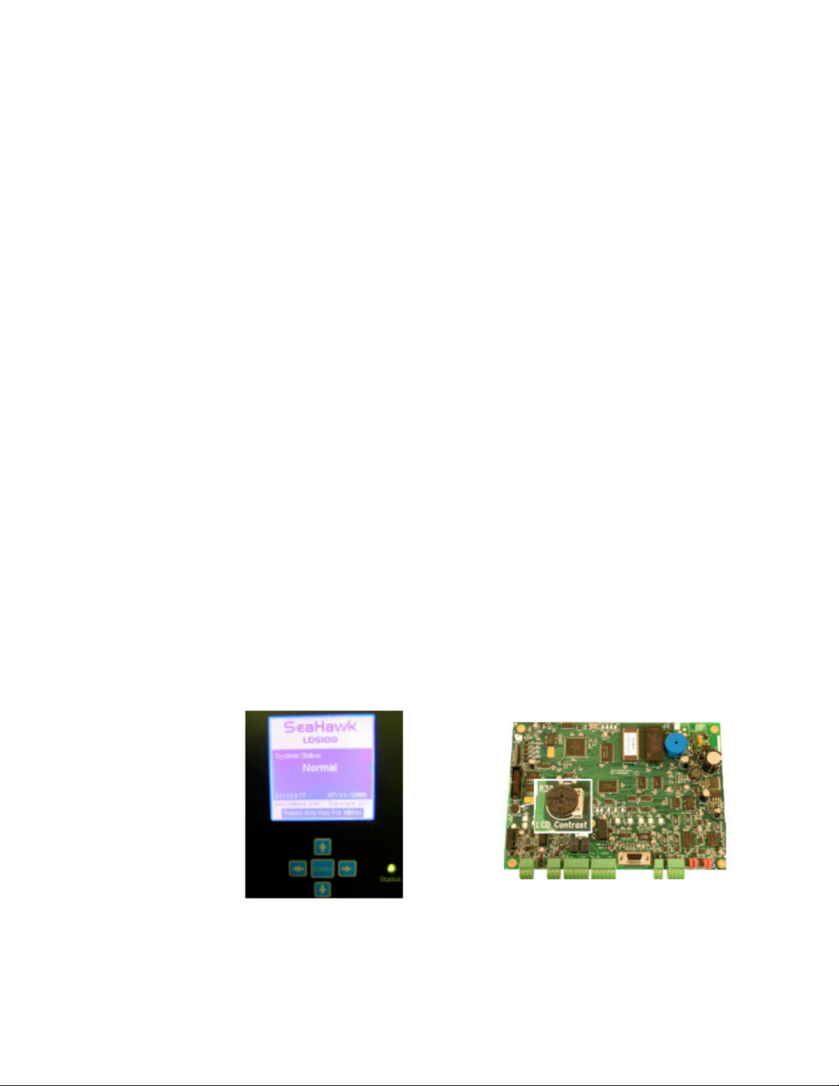
Figure 1.1
www.rletech.com 17 970.484.6510
LD5100 LCD Interface and the R39 Contrast Adjustment (left to right)
Page 18
1 Product Overview
WARNING
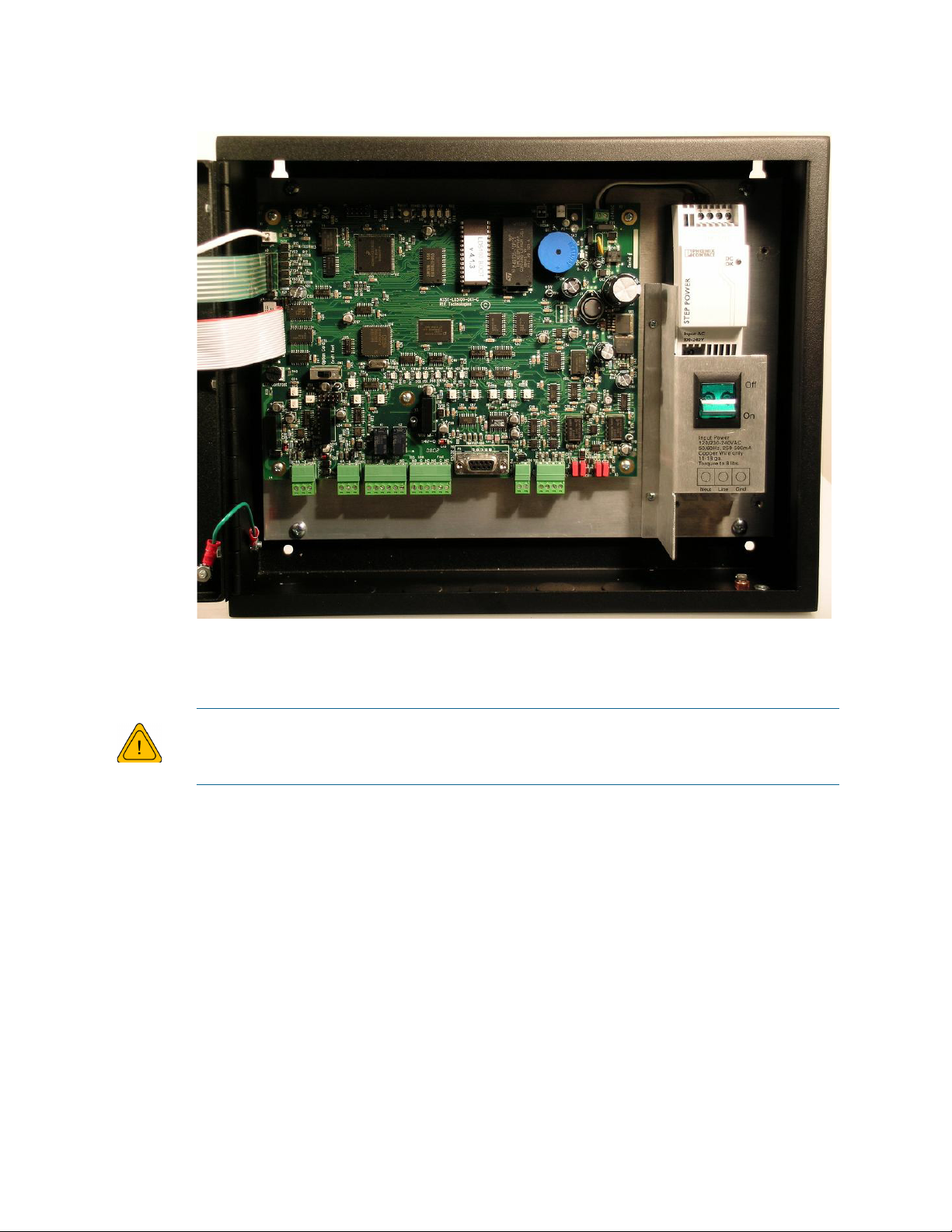
Figure 1.2
LD5100 Enclosure Interior
A dedicated circuit breaker must be provided in the building within close proximity
to the LD5100 and be clearly marked as the disconnecting device for this unit.
www.rletech.com 18 970.484.6510
Page 19
C HAPTER
CHAPTER 0CONNECTIONS AND SETTINGS
The LD5100 is comprised of two boards. The two boards are accessed when the device's front
cover is opened. The display board is located on the inside of the door. The main board is the
large board on the left side of the enclosure.
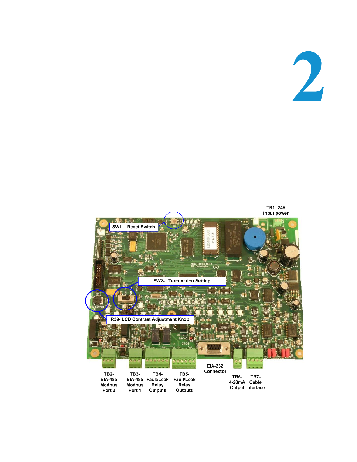
Figure 2.1
www.rletech.com 19 970.484.6510
LD5100 Main Board
Page 20

2 Connections and Settings
2.1. Main Board
The connectors on the main board, found at the bottom of Figure 2.1, are labeled TB2 through
TB7. The connector on the power board is labeled TB3. The reset switch on the main board is
labeled SW1. The termination setting on the main board is labeled SW2.
2.1.1 SW1: Reset Switch
The Reset switch is provided to reset the microprocessor without cycling power to the unit.
2.1.2 SW2: Termination Setting
The Termination Setting switch must ALWAYS be set to the far right. This enables the RS232
port to work properly.
2.1.3 R39: Contrast
This adjustment knob adjusts the 160x160 LCD's contrast. Turn the adjustment knob
clockwise or counterclockwise to adjust the contrast as necessary.
2.1.4 TB1: Input Power
This is a factory wired two position connector with the following connections (for reference
only):
TB1-1 24VDC negative (-)
TB1-2 24VDC positive (+)
2.1.5 TB2 and TB3: RS485 Modbus Port 2 and 1
Terminals TB2 and TB3 connect to a RS485 network. A grounded shield contact is provided
for connection to shielded cable. If the shield contact is used, verify the power connector is
properly grounded and there is no voltage potential between units on the network. The RS485
ports are set to no parity, 8 databits, 1 stop bit (n, 8, 1). Connect the RS485 wires to TB2 or
TB3 on the main board as follows:
TB2-1 A (+)
TB2-2 B (-)
TB2-3 Shield
www.rletech.com 20 970.484.6510
Page 21

2 Connections and Settings
2.1.6 TB4 & TB5: Relays
Terminals TB4 and TB5 are Form C Relay Outputs. Each terminal has two outputs. TB4
provides a connection to one of the leak alarm relay outputs and one of the fault relay outputs;
TB5 provides a second set of contacts for the same leak and fault alarms.
The six contacts on TB4 and TB5 are labeled Leak NO, Leak C, Leak NC, Fault NO, Fault
C, and Fault NC. Connect the alarm relay wires to TB4 and TB5 as follows:
TB4-1 Leak alarm normally open (NO)
TB4-2 Leak alarm common (C)
TB4-3 Leak alarm normally closed (NC)
TB4-4 Fault alarm normally open (NO)
TB4-5 Fault alarm common (C)
TB4-6 Fault alarm normally closed (NC)
TB5-1 Leak alarm normally open (NO)
TB5-2 Leak alarm common (C)
TB5-3 Leak alarm normally closed (NC)
TB5-4 Fault alarm normally open (NO)
TB5-5 Fault alarm common (C)
TB5-6 Fault alarm normally closed (NC)
Two LEDs, labeled K1Fault and K2Leak, are located above TB4 and TB5 in the LED status
strip near the center of the main board. They indicate the status of the relays On/Off. The leak
detection relay is activated when a leak is detected. The cable break relay is activated when a
cable fault is detected.
These relays are set to factory defaulted to Unsupervised; see 5.8.7, “Supervised Relays” on
page 37, for Supervised Relays function.
Both relays (all alarms) can be configured to be latched or unlatched. A latched alarm requires
a manual reset of the system once a leak or cable problem is no longer present.
2.1.7 RS232 Connector
The RS232 port uses only the transmit, receive, and ground pins (2, 3 and 5). The baud rate is
9600. The RS232 port is set to no parity, 8 databits, 1 stop bit (n, 8, 1). A straight through
cable should be used to connect a terminal or PC to the LD5100.
2.1.8 TB6: 4-20mA Output
A 4-20mA loop powered output is provided on TB6. The maximum range (20 mA) can be set
to 1000, 2500, or 5000 feet. Connect the 4-20mA wires to TB6 as follows:
TB6-1 4-20mA positive (+)
TB6-2 4-20mA negative (-)
www.rletech.com 21 970.484.6510
Page 22
2 Connections and Settings
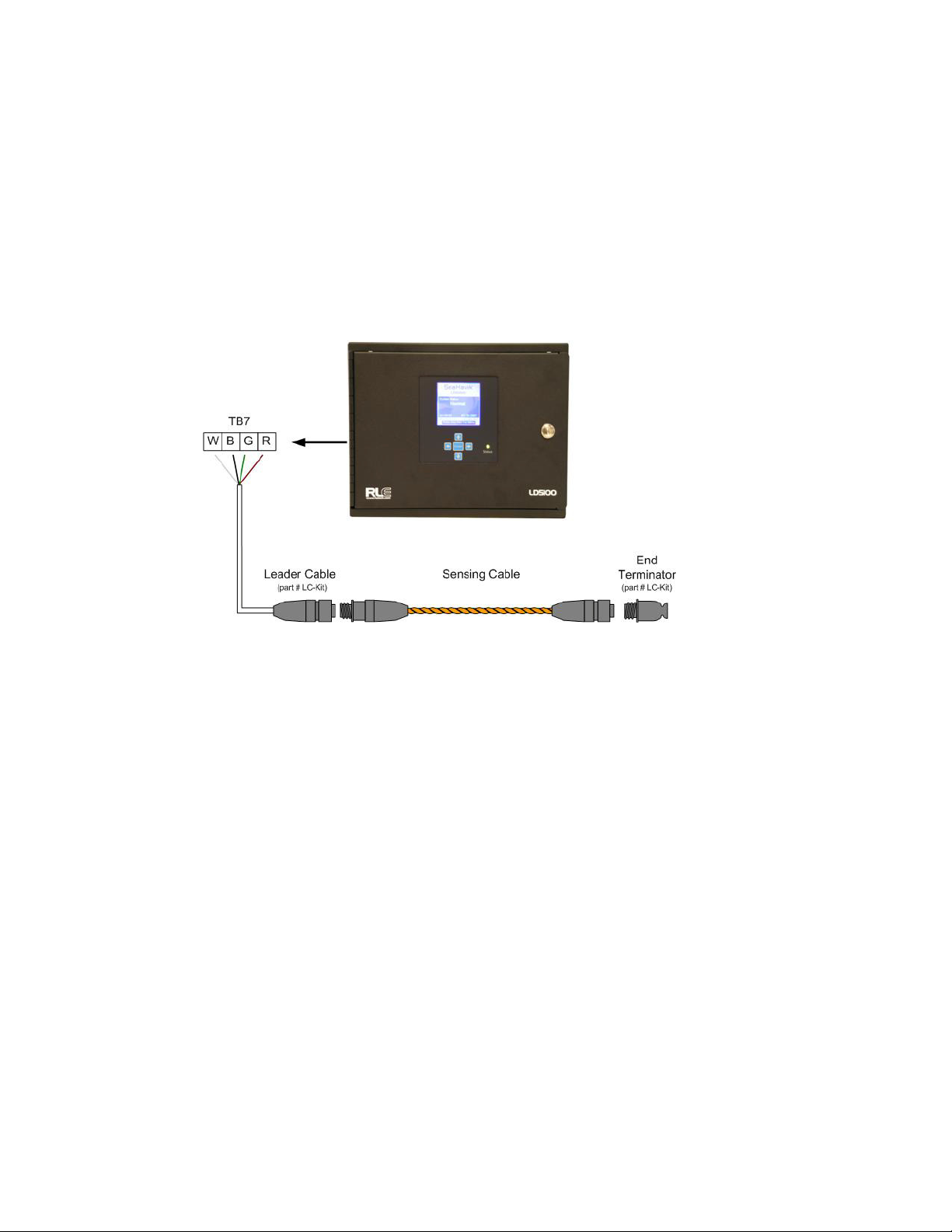
2.1.9 TB7: Cable Interface
The SeaHawk Water Leak Detection Cable (SC) connects to TB7. A 15 foot (4.57m) nonsensing leader cable (part # LC-KIT) is required to connect the LD5100 to the SC cable.
Connect the cable wires to TB7 as follows:
TB7-1 White wire
TB7-2 Black wire
TB7-3 Green wire
TB7-4 Red wire
Figure 2.2
Cable Connections to the Sensing Cable
www.rletech.com 22 970.484.6510
Page 23

2 Connections and Settings
WARNING
2.1.10 AC Power Input
The LD5100 mounted in the metal enclosure requires either a 120 VAC (105-125 VAC) or
230 VAC (205-250 VAC) connection (2 wire & ground). Connect the ground and power wires
to the AC power terminal block. Connect the AC power input as follows:
AC Power Block TB1-1Neutral
AC Power Block TB1-2Line
AC Power Block TB1-3Ground
Figure 2.3
AC Power Input
Make sure the dedicated breaker is in the off position before connecting the AC
power wires to the LD5100.
www.rletech.com 23 970.484.6510
Page 24

2 Connections and Settings
Notes:
www.rletech.com 24 970.484.6510
Page 25

3.1. Installing the Unit
The LD5100 is a wall mounted device. To secure the device to the wall, first remove the
aluminum back panel and all electronics from the enclosure. There are knockouts on the top
and bottom of the enclosure designed to accommodate. 5 inch (12.7mm) conduit. Remove as
many as necessary. There are two holes in the top back of the unit spaced 11 inches (.28m)
apart. Use drywall anchors or suitable anchors depending on the wall construction, to secure
the unit to the wall. Put two more anchors through the two holes in the bottom back of the unit.
Reinstall the back panel and reconnect the electronics.
C HAPTER
CHAPTER 0INSTALLATION
3.2. Connecting the SeaHawk Water Leak Detection Cable (SC)
The LD5100 requires a leader cable kit (part #LC-KIT; purchased separately) which includes
a 15 foot (4.57m) leader cable. One end of this leader cable connects into the LD5100. This
end of the cable has four stripped, bare wires. The other end features a mating connector which
connects with the Sea Hawk Leak Detection Cable (SC). The end of the cable is finished with
a removable end terminator (EOL).
Note A Leader Cable Kit (part #LC-KIT) is required to connect the LD5100 to the SeaHawk Leak
Detection Cable (SC). The kits are not included with the LD5100 and can be purchased
separately.
Connect the 15 foot (4.57m) leader cable to the LD5100. From left to right, with the screws of
the terminal block connector facing up, the wires that screw into the terminal connector should
be colored white, black, green, and red. If the terminal connector is removed from the end of
the cable, make sure the wires are in this same order when the connector is reapplied.
www.rletech.com 25 970.484.6510
Page 26

3 Installation
WARNING
Once the leader cable is plugged into the terminal block, it is ready to be connected to the SC
cable. To do this, unscrew the EOL terminator from the end of the leader cable. Attach the first
length of the SC cable to the leader cable. Route the SC cable according to a cable layout
diagram, if provided. Lay the cable according to the cable installation guidelines on pages 9-
10. Secure the EOL terminator on the unoccupied end of the last section of SC cable.
Figure 3.1
Water Leak Detection Cable (SC)
3.2.1 Securing Cable to the Floor
Secure the SC cable to the floor with either J-clips (Part #JC) or one of the other approved
methods shown in Figure 3.2. Available from RLE and designed specifically for use with the
SC cable, J-clips are the manufacturer's recommended installation method and can be installed
as follows:
Place one J-clip every 3 feet (.914m) along the length of the SC cable and one at each turn
of the cable.
If the cable is installed over an obstruction, clip the cable on both sides, as close to the
obstruction as possible.
Do not install the cable directly in front of an air conditioner. Allow a minimum of 6
feet (1.83m) between the unit and the cable. If the cable is too close to the air
conditioning unit's air stream, the moisture from the humidifier may cause false
leak readings. If the cable must be installed in front of an air conditioning unit,
place the J-clips 3 feet (0.914m) apart.
Note It is important to finish the end of the SeaHawk Water Leak Detection Cable (SC) with the end
terminator (EOL). If the EOL terminator is not present, a cable fault will register. Note any
variances between the cable layout diagram and the actual cable installation.
www.rletech.com 26 970.484.6510
Page 27

3 Installation
WARNING
Figure 3.2
Cable Installation Methods
3.3. Apply Power to the Unit
Once the SC is connected to the unit, power may be applied
A dedicated circuit breaker must be provided in the building within close proximity
to the LD5100 and be clearly marked as the disconnecting device for this unit.
The LD5100 operates between100 - 240 VAC power. An AC power supply should be run to
the location of the unit. Before applying power to the unit, make sure the AC breaker switch is
turned off.
Once the power is turned off, strip the end of the AC supply so the three wires inside are
exposed. Strip the end of the line and neutral wires and feed the ends to the power supply
inside the LD5100 enclosure. The two power wires must now be inserted into the terminal
block in the lower right corner of the enclosure (Power Supply TB1). As indicated in the
enclosure, the line power wire is positioned on the center side of the terminal block (Line).
The neutral wire is placed into the opening on the left side of the terminal block (Neut). The
earth ground line is placed the right side of the terminal block (Gnd).
www.rletech.com 27 970.484.6510
Page 28

3 Installation
Figure 3.3
Lower Right Terminal Block
Once the three wires are connected inside the terminal block, turn the AC power supply back
on. The LD5100 should begin booting up. Wait approximately one minute. No alarm should
be present.
On the LCD, press any key for the main menu. Enter the Cable Status menu. The cable length
is displayed. If this reading varies by more than ±5% of the actual length of cable installed,
verify the installation.
Through the LCD submenus, you may set the clock, system name, alarm configuration, feet/
meters, etc.
Wait at least 30 minutes before calibrating the LD5100. Calibrate the LD5100 through the
front panel System Setup menu.
Map the cable per the instructions in Chapter 6, “Mapping the Cable” on page 41.
www.rletech.com 28 970.484.6510
Page 29

C HAPTER
Figure 4.1
4-20mA Testing
CHAPTER 04-20MA OUTPUT TESTING
The LD5100’s 4-20mA output is loop powered and tested by the manufacturer. The
manufacturer guarantees its performance upon delivery. Should the 4-20mA output need to be
tested in the field, follow these steps. The following procedure is performed with the cable
connected, unless otherwise indicated.
1 Remove the two position plug from TB6.
2 Remove any wires from the terminal and
install a 200Ohm resistor to TB6-2. Then
apply +24V to TB6-1 and ground of the
24V supply to the other side of the
resistor.
3 Reinstall the plug on TB6.
4 With the system on and no alarms present,
measure the DC voltage across the
resistor. A value of 0.8VDC should
register. This equates to 4mA, or normal
operation.
5 Remove the SeaHawk Leak Detection
Cable (SC) and wait for the unit to activate
its cable trouble alarm. Measure the DC
voltage across the resistor. A value of approximately 4.0VDC should be measured. This
equates to 20mA, or a fault alarm. Reconnect the SC cable.
6 Place water on the end of the SC cable. Measure the DC voltage across the resistor. The
value will be proportional to the length of cable measured by the LD5100. A value of
approximately 4.0V, which equates to 20mA, will be read if the length of the cable is
identical to the length read by the LD5100. Dry the cable.
7 Place water on the start of the cable. Measure the DC voltage across the resistor. A
measurement of approximately 0.8VDC, or 4mA, should be measured. This corresponds to
a leak at zero distance. Dry the cable.
8 Remove the resistor from the plug and reattach any wires as necessary.
www.rletech.com 29 970.484.6510
Page 30

4 4-20mA Output Testing
Notes:
www.rletech.com 30 970.484.6510
Page 31

5.1. Default/Idle Display
When the LD5100 is powered up, diagnostics are performed. The boot ROM and flash program
code are verified. While these diagnostics are being performed, the following text is displayed
on the LCD:
C HAPTER
CHAPTER 0LCD INTERFACE
Figure 5.1
www.rletech.com 31 970.484.6510
LD1500 Bootup Screen
Page 32

5 LCD Interface
Once the diagnostics are complete, the LCD displays the following screen:
Figure 5.2
LD5100 Main Screen
Any time a screen within the LCD interface is left idle for more than one minute, it will return to
this default display.
The LCD is accompanied by a five button control panel. The up, down, left and right arrow
keys are used to move the cursor through the display and change corresponding values. Key
legends are displayed at the bottom of the LCD in submenus. The left arrow key is often used as
a “back” button to navigate to a previous screen. The Enter key selects an option and commits
changes.
5.2. Main Menu
From the Main Menu, use the up and down arrow keys to position the arrow on the LCD in
front of the appropriate menu choice. Press the Enter key to select a menu.
Figure 5.3
www.rletech.com 32 970.484.6510
LD5100 Main Menu Screen
Page 33

5.3. View Zones
The View Zones menu will display the available (or user configured) 12 zones of cable and
their appropriate labels. These zones are lengths of cable that a user may configure for the
LD5100 to display during an alarm.
5 LCD Interface
Figure 5.4
LD5100 Default/Unconfigured View Zones Menu
5.4. Cable Status
The Cable Status option displays the Cable Status screen. This screen shows information about
the SeaHawk Leak Detection Cable (SC) attached to the LD5100.
Figure 5.5
LD5100 Cable Status Screen
5.4.1 System Status
During a no alarm condition, the System Status will display Normal. The System Status will
change during an alarm condition and display either a Leak or Cable Break alarm.
www.rletech.com 33 970.484.6510
Page 34

5 LCD Interface
5.4.2 Cable Length
The length of cable installed on the LD5100, in either feet or meters. To change units refer to
5.8.9, “Feet / Meters” on page 37.
5.4.3 Current
This label shows the current on the SC cable. A current will register if there is any conductive
material (e.g., water) detected on the cable.
5.4.4 Contamination Delay (ContamDly)
The Contamination Delay is a counter that begins when the contamination trip point is passed;
see 5.8.4, “Contamination Delay” on page 37 for configuration.
5.4.5 Leak Delay (LeakDly)
The Leak Delay is a counter that begins when the Leak Trip Point is passed; see 5.8.3, “Leak
Delay” on page 37 for configuration.
5.4.6 Leg 1 Resistance (Leg1 Res)
The resistance measured on the first of two legs of the SC cable. Primarily used for advanced
diagnostic purposes.
5.4.7 Leg 2 Resistance (Leg2 Res)
The resistance measured on the second of two legs of the SC cable. Primarily used for advanced
diagnostic purposes.
5.4.8 Cable Relay or Cable Test Relay
The Cable Relay is used to simulate 2500 feet (762m) of cable on the LD5100. This is used
when the SC cable must be disconnected from the LD5100 unit for maintenance or adjustments
without causing a cable break alarm, see 5.8.11, “Cable Test Relay” on page 38 for
configuration.
5.4.9 Firmware Version
This is the version of the firmware that is currently installed and running on the LD5100.
www.rletech.com 34 970.484.6510
Page 35

5.5. Alarm History/Trend Log
The Alarm History/ Trend Log Screen allows users to view the alarm history, trend log, and
erase data from both.
5 LCD Interface
Figure 5.6
LD5100 Cable Status Screen
5.5.1 Alarm History Log
The Alarm History Log displays the most recent 100 events recorded by the unit. Events are
displayed in the following manner:
Date Time
Description whereas:
Date is the date the event occurred.
Time is the time at which the event occurred.
Description is a detail of the nature of the event.
5.5.2 Trend Log
The Trend Log displays the leakage current on the cable. One measurement is taken at the user
set interval (1 min - 1440 min; factory default is 1440 min, or 1 day). The log retains the 288
most recent entries. Analyzing the trend data can help determine the location of long term
contamination build up, or degradation, on the cable.
5.5.3 Erase Alarm History
Erase Alarm History will clear all events log in the history table.
5.5.4 Erase Trend log
Erase Trend log will clear all trend data logged in the trend table.
www.rletech.com 35 970.484.6510
Page 36

5 LCD Interface
5.6. Comm Port Status
The Comm Port Status menu displays the settings and diagnostics of both of the LD5100's
RS485 Modbus ports. This screen will display each port's Modbus address and packets
counters. Press Enter to reset all packet counters displayed.
Figure 5.7
Comm Port Status Screen
5.7. View Map
The View Map option displays all currently mapped points of the LD5100; see Chapter 6,
“Mapping the Cable” on page 41.
5.8. System Setup
The System Setup option displays the System Setup menu. This screen is password protected.
The default password is 1234.
Figure 5.8
www.rletech.com 36 970.484.6510
System Setup Menu
Page 37

5 LCD Interface
5.8.1 Leak Trip Point
The Leak Trip Point option allows users to modify the leak detection trip point for the LD5100.
This trip point helps the system avoid false alarm readings.
5.8.2 Contamination Trip Point
The Contamination Trip Point option allows users to modify the contamination trip point for
the LD5100. This trip point helps the system avoid false alarm readings.
5.8.3 Leak Delay
The Leak Delay is a timer that begins to count down when a leak alarm condition is met. This
timer delays the alarm from registering for a set amount of time. The timer can be set from 5 to
990 seconds.
5.8.4 Contamination Delay
The Contamination Delay is a timer that begins to count down when a leak alarm condition is
met. This timer delays the alarm from registering for a set amount of time. The timer can be set
from 5 to 990 seconds.
5.8.5 Re-Alarm Delay
The Re-Alarm Delay is a counter that, upon expiring, will re-annunciate the last silenced alarm
condition. This counter can be set from 0 (disable) to 24 hours.
5.8.6 Latching Alarms
The Latching Alarms option allows the alarm relays to be set as latching or non-latching. A
latched alarm requires a manual reset of the system once a leak or cable problem is no longer
present.
5.8.7 Supervised Relays
The Supervised Relays option allows users to configure the Leak and Fault relays to be
supervised or unsupervised. A supervised relay is normally activated and will deactivate upon
alarm or loss of power.
5.8.8 4-20MA Max Range
The 4-20mA Max Range allows the user to select the cable range for the 4-20mA output. This
value can be set to 1000, 2500, or 5000 feet (305m, 762m, and 1524m).
5.8.9 Feet / Meters
The Feet/Meters option designates whether the LD5100's distance readings are displayed in
feet or meters.
www.rletech.com 37 970.484.6510
Page 38

5 LCD Interface
5.8.10 Language
The Language option designates whether the LD5100's LCD menus are displayed in English or
French.
5.8.11 Cable Test Relay
The Cable Test Relay option activates the internal test circuit to simulate 2500 feet (762m)
cable. This allows the SC cable to be removed from the LD5100 without causing alarms. The
Cable Test Relay will stay on for 300 seconds and a counter will be displayed.
5.8.12 Restore Defaults
The Restore Defaults option will reset all configurations back to the original factory defaults.
5.8.13 Clock
The Clock option allows users to set the time and date for the LD5100.
5.8.14 Resistance/Foot (Res/Ft)
The Res/Ft option allows users to precisely calibrate the LD5100. Users can adjust the ohms per
foot until the cable length displayed matches the actual cable length installed. The default value
is 2.800 ohms per foot.
www.rletech.com 38 970.484.6510
Page 39

5.9. Zone Setup
The Zone Setup menu will display a table of configured zones. A zone is a set length of cable
that may have a name or description assigned to it. Upon alarm, if a leak distance falls within a
zone’s boundary, the zone's description will appear on the main screen. Zones are configured
by entering the starting distance for the zone, followed by the zone label. The zone’s end
boundary is set by the next zone's starting distance.
5 LCD Interface
Figure 5.9
Note Zone 1 starts at 0 feet/meters and ends at Zone 2’s starting distance.
Example Configuration for Zone 1
Figure 5.10 is an example of the main screen during a leak at 500 feet (152.4m), in Zone 1,
labeled Server Room.
Figure 5.10
Example of the Main Screen during a Specific Condition
www.rletech.com 39 970.484.6510
Page 40

5 LCD Interface
5.10. Point Mapping
The Point Mapping menu allows users to map points on the LD5100. Mapped points help users
to create reference maps for a cable layout. For more details about how to map the cable on the
LD5100 see Chapter 6, “Mapping the Cable” on page 41.
5.11. Comm Port Settings
The Comm Port Settings menu allows users to configure both of the LD5100’s RS485 Modbus
ports. The LD5100 is only configurable as a Modbus slave device. Both ports may have their
addresses and baud rates set in this menu. Both addresses may be different and can be
configured from 0 (disabled) to 254. Both baud rates can be different and can be configured as
1200, 2400, 9600 (default), or 19200.
To set the ports, use the up and down arrows to navigate to the desired Port #. Then push the
right arrow to select the field. Use the up and down arrows to select the desired setting.
The Leak Detection Master option enables slave units to activate the LD5100 when they are
triggered into an alarm state. This function is beneficial when the LD5100 is a remote system
that does not have personnel in the immediate vicinity to monitor the alarm status.
When using the leak detection master option, the LD5100 relays can be activated according to
the slave unit alarm. If the slave has a leak alarm or a cable break alarm, the LD5100 leak or
cable relay will change state, respectively (i.e. it will trigger that an alarm is present. The zone
will then appear on the LCD and an alarm state will be reported to the top level of the system.
Figure 5.11
Comm Port
www.rletech.com 40 970.484.6510
Page 41

C HAPTER
CHAPTER 0MAPPING THE CABLE
After the SeaHawk Water Leak Detection Cable (SC) is laid in the desired configuration, the
cable can be mapped. Mapping the cable improves the accuracy of the LD5100 reference map
and makes it easier to locate a leak.
To ensure the cable has been installed properly, RLE recommends testing the cable in a few
spots before mapping the system,.
The LD5100 computes the distance from the control panel to the leak along the length of SC
cable attached to the unit. In most cases, the SC cable is laid in a curved or serpentine pattern.
This may make it difficult to locate a leak when given a linear distance. To help alleviate this
problem, identify a series of easily accessible, evenly spaced points along the cable length.
Number the points, and record their locations on the cable reference map (part #FM1114)
provided by RLE, or refer to the directions for creating a map below (6.1., “Mapping
Directions” on page 42). Use the numbered points to map the cable. Then, when the unit
detects a leak, the location of the leak can be determined by comparing the distance shown on
the control panel with the known positions along the cable as recorded on the reference map.
Note Calibrate the LD5100 prior to mapping by adjusting the Resistance per Foot reading; see
5.8.14, “Resistance/Foot (Res/Ft)” on page 38 for more details. This allows the LD5100
measured cable length to accurately reflect the actual cable length installed.
www.rletech.com 41 970.484.6510
Page 42

6 Mapping the Cable
WARNING
6.1. Mapping Directions
1 If a cable reference map (part #FM114) was not ordered from RLE Technologies, LD5100
users must create a drawing that represents the floor plan. This drawing must include the
room layout (walls, doors, and other permanent structures), the SC cable routing path, any
jumper sections of non-sensing cable (NSC) and any weighted cable connectors/simulators
(WCCS). Marking up a CAD drawing of the Facility works the best.
2 Physically identify points along the cable routing path. The points should be easily
accessible and evenly spaced. Number the points and record their location on the reference
map. Note where the connectors are located along the cable run.
3 Using the front panel of the LD5100, select Point Mapping and press Enter.
4 To test the map, wrap a wet paper towel or sponge or pour a small puddle of water around
the cable at one of the previously mapped points. The LD5100 produces a short beep within
approximately 30 seconds. The LCD displays the LD5100's calculated distance to the leak.
Remove the paper towel and dry the cable. Within approximately 20 seconds, the LD5100
produces a long beep indicating the short is removed and the system has returned to normal.
Tip If the individual mapping the cable is not in a position to hear the audible alarm, wait two
minutes between each point. This ensures the system has had time to stabilize.
Loss of power or re-entering the Point Mapping menu will cause all mapping data
to be lost (reset).
5 When mapping is complete, press the Left arrow key on the LD5100 to exit the mapping
mode.
6 Select View Map on the LCD and record the LD5100's reading of each point on the
reference map.
7 Mount the cable reference map alongside to the LD5100 control panel or the remote
display. When a leak or cable break occurs, refer to the map and the distance displayed on
the LD5100 to determine the physical location of the leak.
www.rletech.com 42 970.484.6510
Page 43

C HAPTER
WARNING
CHAPTER 0EIA-232 INTERFACE
The EIA-232 Interface is used primarily for advanced diagnostic and configuration.
The Bootloader section is designed for experienced technicians or users
responsible for maintaining the system. EXIT IMMEDIATELY if you are not
trained in the use of the Bootloader commands.
Contact the manufacturer for more information regarding the commands in this
section.
7.1. Boot Up
Make sure the EIA-232 port is connected to a PC or terminal with a straight through cable (not
provided). Run terminal emulation software (i.e., HyperTerminal) and make sure the settings
match the LD5100 EIA-232 port configuration; see 2.1.7, “RS232 Connector” on page 21 for
port configuration details. When the LD5100 is powered up, diagnostics are performed. The
boot ROM and flash program code are verified. Output similar to Figure 7.1 should appear on
the terminal or terminal emulation software.
www.rletech.com 43 970.484.6510
Page 44

7 EIA-232 Interface
Figure 7.1
EIA-232 Bootup Screen
7.2. Main Menu
Once the system is entirely booted, press the Enter key on your PC or terminal to display the
Main Menu.
Figure 7.2
EIA-232 Main Menu Screen
www.rletech.com 44 970.484.6510
Page 45

7.3. SC – System Configuration
The SC function command displays a submenu that lists all items in the System Configuration
Menu.
7 EIA-232 Interface
Figure 7.3
EIA-232 SC Function Screen
7.3.1 Modify LCD Password – 1
Selection 1, Modify LCD Password, will allow users to set a new LCD password for the
System Setup LCD menu. A four digit number must be entered in place of the default 1234
password. A password of 0000 will disable all password protection on the LD5100.
7.3.2 Zone Setup – 2
Selection 2, Zone Setup, will allow users to configure zones. Zones are lengths of cable that
may have a label, or description, associated with them.
Zones begin by the Zone Distance, or starting length, and end with the next zone's beginning
Zone Distance; Note: Zone 1 always starts with Zone Distance of 0 ft. Enter a Zone Distance
in the format dxx where xx is the zone number. A user will then be prompted to enter the
beginning length for the zone. For example, to set Zone 2 to begin at 1000 feet (305m), type
d2 and press Enter. Then type 1000 and press Enter when prompted for zone distance.
Enter a zone’s description in the format lxx where xx is the zone number. A user will then be
prompted to enter the description for the zone. A description can be up to fifteen characters in
length.
www.rletech.com 45 970.484.6510
Page 46

7 EIA-232 Interface
7.3.3 Diagnostics – 3
Selection 3, Diagnostics, will allow users to open the LD5100's Diagnostic menu. This menu
is primarily used for advanced diagnostics and troubleshooting.
Figure 7.4
EIA-232 Diagnostics Menu
The options available on the Diagnostics Menu are described in Table 7.1.
Table 7.1
Option Description
Cable Readings – 1 Selection 1 displays the current cable readings, including
Set 4-20mA Output – 2 Selection 2 allows a user to manually set the 4-20mA
Cable Relay On – 3 Selection 3 turns the internal cable test relay on.
Cable Relay Off – 4 Selection 4 turns the internal cable test relay off.
Output Relay K1 On – 5 Selection 5 turns the Leak relay on.
Output Relay K1 Off – 6 Selection 6 turns the Leak relay off.
Output Relay K2 On – 7 Selection 7 turns the Fault relay on.
Output Relay K2 Off – 8 Selection 8 turns the Fault relay off.
Diagnostic Menu Options
both cable length and any present current leakage.
output to test its function.
www.rletech.com 46 970.484.6510
Page 47

7.4. Other Main Menu Functions
The remainder of the functions available from the Main Menu of the EIA-232 interface are
described in Table 7.2.
7 EIA-232 Interface
Table 7.2
Option Description
LS – Leak Status LS displays the current cable readings, including both
AR – Alarm Reset AR resets all alarm relays. This command forces all alarms
AH – Alarm History AH displays the Alarm History Log.
CH – Clear Alarm History CH clears the Alarm History Log.
TD – Trend Data Table TD displays the Trend Data Table, which monitors and
CT – Clear Trend Data Table CT clears all records from the Trend Data Table.
TI – Display Date/time TI displays the LD5100’s current date and time
MT ON – Measurement Trace OnMT ON displays advanced manufacturer diagnostics of the
MT OFF – Measurement
Trace Off
MBT – Modbus Trace On MBT shows Modbus trace.
Other Main Menu Functions
cable length and any present current leakage.
off. If an alarm condition is still present after the AR
command is executed, the alarm is reactivated. If an alarm
is still active after the AR command is executed, it will not
be re-entered in the Alarm History Log.
displays leakage current.
microprocessor.
MT OFF turns off the display of advanced manufacturer
diagnostics of the microprocessor.
MBS – Modbus Stats MBS shows Modbus stats.
EX – Exit EX is used to enter the Bootloader command section. The
unit will stop monitoring cable and allow firmware updates
to be loaded. To restore normal operation after updating
firmware, type RUN and press the Enter (<-|) key on the
keyboard, or power the unit off and then back on again.
www.rletech.com 47 970.484.6510
Page 48

7 EIA-232 Interface
Notes:
www.rletech.com 48 970.484.6510
Page 49

CHAPTER 0MODBUS COMMUNICATION
This document describes the Modbus communications protocol as supported by the LD5100
Water Leak Detection System. It includes details and information on how to configure the
LD5100 for communications via Modbus network.
8.1. Implementation Basics
C HAPTER
The LD5100 is capable of communicating via the half-duplex RS485 serial communication
standard. The LD5100 is configured to act as a slave device on a common network. The
RS485 medium allows for multiple devices on a multi-drop network. The LD5100 is a slave
only device and will never initiate a communications sequence.
8.1.1 Modes of Transmission
The Modbus protocol uses ASCII and RTU modes of transmission. The LD5100 supports only
the RTU mode of transmission, with 8 data bits, no parity and one stop bit. Every Modbus
packet consists of four fields:
Slave Address Field
Function Field
Data Field
Error Check Field (Checksum)
8.1.1.1 Slave Address Field
The slave address field is set by the going into local 160x160 display on the front panel. Go to
COMM PORT SETTINGS from the Main Menu screen. Select the Modbus Slave address and
the baud rate to be used for either/or EIA-485 Port1 and EIA-485 Port2.
www.rletech.com 49 970.484.6510
Page 50

8 Modbus Communication
8.1.1.2 Function Field
The function field is one byte in length and tells the LD5100 which function to perform. The
supported functions are 03 (Read 4xxxx output registers), 04 (Read 3xxxx input registers), 06
(Preset single register) and 16 (Preset multiple registers).
8.1.1.3 Data Field
The data field of the request is a variable length depending on the function. The data fields for
the LD5100 are 16-bit registers, transmitted high order byte first (big-endian).
8.1.1.4 Error Check (Checksum) Field
The checksum field lets the receiving device determine if the packet has transmission errors.
The LD5100 RTU mode uses a 16-bit cyclic redundancy check (CRC-16).
8.1.2 Exception Responses
If a Modbus master sends an invalid command to the LD5100 or attempts to read an invalid
register, an exception response is generated. The response packet will have the high order bit
of the function code set to one. The data field of the exception response contains the exception
error code.
Table 8.1
Code Name Description
01 Illegal Function The function code is not supported
02 Illegal Data Address Attempt to access an invalid address
03 Illegal Data Value Attempt to set a variable to an invalid value
Exception Codes
www.rletech.com 50 970.484.6510
Page 51

8 Modbus Communication
8.2. Packet Communications For The LD5100
This section covers the registers, their names, and a brief description of what they refer to.
8.2.1 Function 03: Read Output Registers
To read the LD5100 parameter values, the master must send a Read Output Registers request
packet. The Read Output Registers request packet specifies a start register and the number of
registers to read. The start register is numbered from zero (40001 = zero, 40002 = one, etc).
Table 8.2
Read Registers Request Packet Read Registers Response Packet
Slave Address (1 byte) Slave Address (1 byte)
03 (Function code) (1 byte) 03 (Function code) (1 byte)
Start Register (2 bytes) Byte count (1 byte)
# of registers to read (2 bytes) First register (2 bytes)
Crc Checksum (2 bytes) Second register (2 bytes)
Read Output Registers Packet Structure
…
Crc Checksum (2 bytes)
www.rletech.com 51 970.484.6510
Page 52

8 Modbus Communication
Table 8.3
Output Registers
Register Name Description Units Range
40001 Leak Threshold Trip current for leak alarm Amps 0-65535
40002 Contamination
Trip current for contamination alarm Amps 0-65535
Threshold
40003 Re-Alarm Re-Alarm delay Minutes 0-65535
40004 Latched Alarm Latching Alarms 0=No 1=Yes 0-65535
40005 Silence Alarm Set to 1 to silence audible alarm 1=Silence 0-65535
40006 Reset Alarm Set to 1 to reset alarms 1=Reset
0-65535
Alarm
40007 Spare 0-65535
40008 Spare 0-65535
40009 Spare 0-65535
40010 Month Clock 1-12 0-65535
40011 Day Clock 1-31 0-65535
40012 Year Clock 00-99 0-65535
40013 Hour Clock 0-23 0-65535
40014 Minutes Clock 0-59 0-65535
40015 Seconds Clock 0-59 0-65535
40016 Seconds Leak Alarm Delay 20-3600 0-65535
40017 Seconds Contamination Alarm Delay 20-3600 0-65535
www.rletech.com 52 970.484.6510
Page 53

8 Modbus Communication
8.2.2 Function 04: Read Input Registers
To read the LD5100 input values, the master must send a Read Input Registers request packet.
The Read Input Registers request packet specifies a start register and the number of registers
to read. The start register is numbered from zero (30001 = zero, 30002 = one, etc).
Table 8.4
Read Registers Request Packet Read Registers Response Packet
Slave Address (1 byte) Slave Address (1 byte)
04 (Function code) (1 byte) 04 (Function code) (1 byte)
Start Register (2 bytes) Byte count (1 byte)
# of registers to read (2 bytes) First register (2 bytes)
Crc Checksum (2 bytes) Second register (2 bytes)
Read Input Registers Packet Structure
…
Crc Checksum (2 bytes)
www.rletech.com 53 970.484.6510
Page 54

8 Modbus Communication
Table 8.5
Input Registers
Register Name Description Units Range
30001 Status Bit level status None 0-65535
30002 Leak Distance Location of leak Ft/Meters 0-65535
30003 Units Unit of measure 1=Ft
0-65535
0=Meters
30004 Leak Current Leakage current on cable Amps 0-65535
30005 Cable Length Installed cable length Ft/Meters 0-65535
30006 Loop1 Res Resistance of cable Ohms 0-65535
30007 Loop2 Res Resistance of cable Ohms 0-65535
30008 Res/Ft Resistance of cable Ohms x1000 0-65535
30009 Version Firmware version xx.xx X 100 0-65535
30010 Virtual Zone Alarm Status Bit Level Status None 0-65535
30011 Modbus Zone Enabled Flags Bit Level Status None 0-65535
30012 Modbus Zone2 Status Bit Level Status None 0-65535
30013 Modbus Zone2 Distance Location of leak Ft/Meters 0-65535
30014 Modbus Zone3 Status Bit Level Status None 0-65535
30015 Modbus Zone3 Distance Location of leak Ft/Meters 0-65535
30016 Modbus Zone4 Status Bit Level Status None 0-65535
30017 Modbus Zone4 Distance Location of leak Ft/Meters 0-65535
30018 Modbus Zone5 Status Bit Level Status None 0-65535
30019 Modbus Zone5 Distance Location of leak Ft/Meters 0-65535
30020 Modbus Zone6 Status Bit Level Status None 0-65535
30021 Modbus Zone6 Distance Location of leak Ft/Meters 0-65535
30022 Modbus Zone7 Status Bit Level Status None 0-65535
30023 Modbus Zone7 Distance Location of leak Ft/Meters 0-65535
30024 Modbus Zone8 Status Bit Level Status None 0-65535
30025 Modbus Zone8 Distance Location of leak Ft/Meters 0-65535
30026 Modbus Zone9 Status Bit Level Status None 0-65535
30027 Modbus Zone9 Distance Location of leak Ft/Meters 0-65535
30028 Modbus Zone10 Status Bit Level Status None 0-65535
30029 Modbus Zone10 Distance Location of leak Ft/Meters 0-65535
30030 Modbus Zone11 Status Bit Level Status None 0-65535
30031 Modbus Zone11 Distance Location of leak Ft/Meters 0-65535
30032 Modbus Zone12 Status Location of leak None 0-65535
30033 Modbus Zone12 Distance Bit Level Status Ft/Meters 0-65535
Registers 30011 through 30033 are dedicated registers for modbus master; see Appendix B, “Leak
Detection Modbus Master” on page 61.
www.rletech.com 54 970.484.6510
Page 55

8 Modbus Communication
Table 8.6
Status Flags (Register 30001)
Bit Description
00 1 = Leak is Detected
01 1 = Cable Break Alarm
02 1 = Contamination is detected
03-15 Spare
Table 8.7
Status Flags (Register 30010)
Bit Description
00 1 = Zone1
01 1 = Zone2
02 1 = Zone3
03 1 = Zone4
04 1 = Zone5
05 1 = Zone6
06 1 = Zone7
07 1 = Zone8
08 1 = Zone9
09 1 = Zone10
10 1 = Zone11
11 1 = Zone12
www.rletech.com 55 970.484.6510
Page 56

8 Modbus Communication
Table 8.8
Bit Description
00 1 = Not enabled
01 1 = Enabled, b1=MBZ2
02 1 = MBZ3
03 1 = MBZ4
04 1 = MBZ5
05 1 = MBZ6
06 1 = MBZ7
07 1 = MBZ8
08 1 = MBZ9
09 1 = MBZ20
10 1 = MBZ11
11 1 = MBZ12
Table 8.9
Status Flags (Register 30011)
Status Flags (Register 30012 - 30033)
Bit Description
00 1= Leak Detected
01 1 = Cable Break
02 1 = Contamination
07 1 = Communication Loss
8.2.3 Function 06: Preset Single Register
To set the LD5100 parameter value, the master must send a Preset Single Register request
packet. The Preset Single Register request packet specifies a register and the data to write to
that register. The register is numbered from zero (40001 = zero, 40002 = one, etc).
Table 8.10
Preset Register Request Packet Preset Register Response Packet
Slave Address (1 byte) Slave Address (1 byte)
06 (Function code) (1 byte) 06 (Function code) (1 byte)
Register (2 bytes) Register (2 byte)
Data (2 bytes) Data (2 bytes)
Preset Single Register Packet Structure
Crc Checksum (2 bytes) Crc Checksum (2 bytes)
www.rletech.com 56 970.484.6510
Page 57

8 Modbus Communication
8.2.4 Function 16: Preset Multiple Registers
To set multiple LD5100 parameter values, the master must send a Preset Multiple Registers
request packet. The Preset Multiple Register request packet specifies a starting register, the
number of registers, a byte count and the data to write to the registers. The register is
numbered from zero (40001 = zero, 40002 = one, etc).
Table 8.11
Preset Registers Request Packet Preset Registers Response Packet
Slave Address (1 byte) Slave Address (1 byte)
16 (Function code) (1 byte) 16 (Function code) (1 byte)
Start Register (2 bytes) Start Register (2 bytes)
# of registers to write (2 bytes) # of registers (2 bytes)
Byte Count (1 byte) Crc Checksum (2 bytes)
Data (2 bytes)
…
…
Crc Checksum (2 bytes)
Preset Multiple Registers Packet Structure
www.rletech.com 57 970.484.6510
Page 58

8 Modbus Communication
8.3. RTU Framing
The example below shows a typical Query/Response from the LD5100 module.
Table 8.12
Slave
Address
02 04 00 00 00 03 B5 A3
Table 8.13
Slave
Address
02 04 06 00 00 00 00 00 01 B5 A3
Query Sample
Function
Code
Response Sample
Function
Code
Starting
Register
“Msb”
Count
Bytes of
Data
Starting
Register
“Lsb”
Register
Data
Msb Lsb
Numbers
of
Registers
“Lsb”
Register
Data
Msb Lsb
Number of
Registers
“Lsb”
Register
Data
Msb Lsb
CRC 16
“Lsb”
CRC 16
“Lsb”
Slave address 2 responds to Function Code 4 with 6 bytes of hexadecimal data and ends with
CRC16 checksum
Register Values:
40001 = 0000 (hex)
40002 = 0000 (hex)
40003 = 0001 (hex)
CRC
“Msb”
CRC 16
“Msb”
www.rletech.com 58 970.484.6510
Page 59

CHAPTER 0UPDATING FIRMWARE
Firmware updates are available on the Documentation/Files section of the LD5100 webpage at
www.rletech.com. Download the appropriate firmware to an accessible place to upload via
RS232 (9600 baud, 8, N, 1) port through a PC or terminal (see Chapter 7, “EIA-232 Interface”
on page 43).
A.1. Updating the Flash Firmware
A PPENDIX
To start the update process, wait for the ten second delay window during power up and press
“ESC” to stop the Flash Main Program from executing. Or if the Flash Main Program is
already running, type “EX” to exit.
The Flash Main Program must be erased before an upload can be preformed. To erase the
code, type the “ERASE PRGM” command. After a second or so, the screen will display
“OK.”
Next, type the “LOAD PRGM XMODEM” command. This will upload the new firmware
file using X-Modem-1k protocol. Go to the top of the screen and left click on transfer, then
click on send file. Select 1K X Modem from the protocol selection and then browse to where
the firmware files are saved. The file must be binary with a.bin extension. Once the proper file
is selected, click open. Then click “send.” This might have to be repeated if this is the first
time uploading firmware.
After the file has been uploaded, enter the “RUN” command, or power down the LD5100 and
then turn it back on.
Note Go to the Products/LD5100 section on the LD5100 webpage of our website at
www.rletech.com for the latest LD5100 firmware file.
www.rletech.com 59 970.484.6510
Page 60

A Updating Firmware
Notes:
www.rletech.com 60 970.484.6510
Page 61

A PPENDIX
CHAPTER 0LEAK DETECTION MODBUS MASTER
This feature allows the LD5100 to act as a Modbus master, so it can talk to other RLE distance
read panels. Up to 11 RLE distance read panels can be connected to the EIA-485 port#1 on the
LD5100. The system status can be viewed by using the view zones menu. The LD5100 will
display leak, cable break, cable contamination, and loss of communications alarms from the
slave units connected to it.
B.1. Connecting Distance Read Panels to the LD5100
When using the LD5100 as a Modbus master, the slave unit(s) must be wired to the EIA-485
port #1 (TB3). Port #2 (TB2) on the LD5100 can only be used as a Modbus slave output.
Using a two wire configuration, connect the slave units in a 485 daisy chain. You will have to
set the EIA-485 slave address in each Leak detection unit. The first unit connected must be set
to address 2. The following units will increase in numeric order by one unit (e.g., the next unit
would be set to address 3, the following would be set to address 4, etc.; see Figure B.1.)
Figure B.1
www.rletech.com 61 970.484.6510
LD5100 Connection Diagram
Page 62

B Leak Detection Modbus Master
B.2. Configuring the LD5100 Via the Local Display
(LCD)
First, the Com Port Setting must be configured on the LD5100:
1 From the main menu, press any of the buttons. Move the cursor down and select the Com
Port Settings, press Enter to the access menu.
2 The cursor will be to the left of Port1, press the Enter. Push the DOWN arrow to change the
type from Modbus-Slave to Modbus-Master, press Enter to save the change.
3 Push the LEFT arrow to get out of the Com Port Settings menu.
4 Select the Zone Setup menu and press Enter.
5 Zone #1 will be set as Master. If desired, assign a name to the Master. The labels for the
Zones can be up to 15 characters long, including spacing.
6 Move the cursor down one space to the number two position, press Enter.
7 Press either the UP or DOWN arrow to select the Slave option for the address.
8 Press the RIGHT arrow to move the cursor in the label field, then enter you label, press
Enter once complete to save your changes.
9 Follow steps 6-8 for configuring Zones 3-12, as needed.
10Once completed configuring the zones, you can go to the View Zones screen and view the
status.
11RLE recommends generating alarms from each panel to ensure proper communication.
12You can configure the LD5100 relays to change state according to the slave unit alarm. If
the slave has a leak alarm or a cable break alarm, the leak or cable relay, will change state,
respectively.
Note You can only have fifteen characters per label field; this includes spaces.
Figure B.2
www.rletech.com 62 970.484.6510
Sample Set-up Screens
Page 63

B Leak Detection Modbus Master
B.3. Configuring the LD5100 Via the EIA-232 (Craft)
Port
First, the Com Port Setting must be configured on the LD5100:
1 Using the Local display (LCD) on the LD5100 press any of the buttons. Move the cursor
down and select the Com Port Settings, press Enter to access the menu.
2 The cursor will be to the left of Port1, press the Enter key.
3 Push the DOWN arrow to change the type from Modbus-Slave to Modbus-Master, press
Enter to save the changes.
4 Connect the straight through male-female DB-9 serial cable from your laptop, or PC, to the
EIA-232 port on the LD5100.
5 Open the terminal emulation program (HyperTerminal) with a connection of 9600 Baud, 8
Data bits, Parity None, 1 Stop bit and Flow control set to off.
6 Press the Enter key on your laptop, or PC, to view the LD5100 Help menu.
7 Type “SC” to access the System Configuration menu (see Figure B.3).
Figure B.3
www.rletech.com 63 970.484.6510
Configuration Menu from EIA-232 Connection
Page 64

B Leak Detection Modbus Master
8 Type “2” for configuring the Zone Setup.
9 To configure Input #2, type D2, then press Enter.
10Press “1” to enable the zone then press Enter.
11To assign a label to that field type “L2”, then press Enter. You can enter the label desired
for that Slave device. You can enter 15 characters per label, including spaces.
12Repeat steps 7-9 to configure any remaining slave devices.
13Once completed configuring the zones, go to the View Zones screen on the local display
(LCD) to view the status.
14RLE recommends generating alarms from each panel to ensure proper communication.
www.rletech.com 64 970.484.6510
Page 65

A PPENDIX
CHAPTER 0PREVENTIVE MAINTENANCE
Follow these steps monthly to test the system and ensure that the control panel is functioning
properly:
1 Place water on the cable.
2 Verify the Leak Detected alarm on the control panel.
3 Compare the distance reading on the LD5100 LCD to the reference map to verify that the
LD5100 displays the correct leak location.
4 Dry the cable and verify that the LD5100 returns to normal.
5 Remove the end-of-line terminator.
6 Verify the Cable Break alarm on the control panel.
7 Reinstall the end-of-line terminator.
8 Verify that the LD5100 returns to normal.
Monitor the cable current monthly to verify that the cable is not being contaminated. The
LD5100 will alarm on cable contamination if the contamination is excessive.
1 From the LD5100 display, press the “Enter” key and navigate to the Cable Status menu.
2 Be sure the cable current is less than 25A. If the cable current is greater than 25A, it is
recommended to troubleshoot the cables to determine which cable is contaminated. The
contaminated cable should be removed, cleaned, retested and reinstalled.
www.rletech.com 65 970.484.6510
Page 66

C Preventive Maintenance
Notes:
www.rletech.com 66 970.484.6510
Page 67

A PPENDIX
CHAPTER 0TROUBLESHOOTING
Table D.1
Troubleshooting Problems with the LD5100
Problem Action
Control Panel will not
Power Up
1 Check with a DVOM (multi-meter) for AC input power on the
lower right hand terminal block on the Power board. If the Input
Selector Switch is set for 115, voltage should be between 105
and 125 VAC. If the Input Selector Switch is set for 230, voltage
should be between 205 and 250 VAC. If no AC power is present
at terminal block, check the circuit (breaker) the LD5100 control
panel is powered by. If voltage is present, go to step 2.
2 Check for 24 VDC at terminal block TB1 pins 1 and 2. If no
voltage is present across these pins, the Power board has failed.
Contact RLE Technologies for replacement. If voltage is present
and no LED's are illuminated, contact RLE Technologies for
further troubleshooting.
Unit Powers Up
without Proper
1 Open the front door and verify that the supply wires are
connected to the display board (LCD panel).
Display on LCD
2 Check the R39 contrast Potentiometer located on the left middle
section of the main board. Adjust the dial and verify that
characters are appearing on the LCD. If the LCD is still not
working, go to step 3.
3 Check the ribbon cable attached to the display board. Verify that
the connectors are all the way in place. If ribbon cable is in place
and the LCD is still not displaying correctly, contact RLE
Technologies for further support.
www.rletech.com 67 970.484.6510
Page 68

D Troubleshooting
Table D.1
Troubleshooting Problems with the LD5100 (continued)
Problem Action
Cable Break Alarm
1 Verify that the leader cable from the SC cable run is plugged into
terminal block TB7.
2 Verify that the end-of-line terminator is installed on the end of the
orange sense cable run. If present at the end of the cable run, go
to step 3.
3 Remove the end-of-line terminator (EOL) from the end of the
cable run and install it onto the end of the leader cable coming
from the control panel. If the condition clears, there is a
damaged/faulty section of SC cable. Start moving the end-of-line
terminator to the end of each section of SC cable to isolate the
faulty section. If the condition does not clear, go to step 4.
4 Power down (shut off) the control panel. Remove terminal block
TB7 from the main board. Remove the four conductors from the
leader cable wire going into the four position terminal block.
Install a jumper wire between pins 1 and 2 and another jumper
wire between pins 3 and 4. Reinstall the terminal block back into
TB2. If the cable break condition clears, there is a problem with
the leader cable. If the condition does not clear, contact RLE
Technologies for further support.
Control Panel not
Calculating Proper
Length of Cable
1 First verify the proper wiring order into terminal block TB7. Wiring
color code should be as follows from left to right: White, Black,
Green and Red.
2 Calibrate your cable. To do this, adjust the Resistance per Foot
(see 5-8.14: Resistance / Foot on page 19 for details). If the
condition does not change, please contact RLE Technologies.
The control panel is pre-calibrated from the factory. The overall
footage should be within 5% of actual installed length.
www.rletech.com 68 970.484.6510
Page 69

D Troubleshooting
Table D.1
Troubleshooting Problems with the LD5100 (continued)
Problem Action
Control Panel not
Calculating Proper
Leak Distance
1 Check the distance on the cable run to verify that the control
panel is monitoring. Verify there is no water along the cable run.
Check to see if multiple leaks are present on the cable. The first
leak should be read and latched by the system; however, if the
system is updated or simultaneous leaks occur (2 or more) within
30 seconds of the initial leak, the system may display the
average distance (distance of the first leak + distance of the
second leak / 2). If no water is present, go to step 2.
2 Power down (shut off) the control panel and remove the end-of-
line terminator (EOL) from the end of the SC cable. Locate the
first section of SC cable from the LD5100 control panel. Where it
joins to the second section of cable, disconnect and install the
End-of-Line terminator at the end of the first section of SC cable.
Turn power back on at control panel. Once the control panel runs
for five to ten minutes, use a damp cloth, rag or paper towel and
place it on the end of the orange SC cable. If the leak is
calculated correctly, remove the end-of-line terminator;
reconnect the SC cable and move down to the next section of
cable. Repeat this process until a faulty reading is obtained. If
the reading is off at the first section of cable, there may be
miscalculations from the LD5100 unit, please contact RLE
Technologies for support.
Cable Contamination
Alarm Units Alarm
History Displays:
1 To clear a contamination alarm, the cable must be removed and
cleaned. Usually the cable can be cleaned by pulling it through a
clean damp rag.
“Cable Contaminated
@ XXXX Ft”
2 If the cable is contaminated by oil, Glycol or chemicals, the cable
can be washed. Use a mild detergent solution of 1 capful to 2
gallons lukewarm water (<105°F). Agitate the cable in a suitable
container, rinse with clear lukewarm water and wipe dry with a
clean towel. The cable may also be cleaned by wiping it down
with Isopropyl Alcohol.
3 Retest the cable by connecting it to the LD5100 before
reinstalling it under the floor.
Note Contamination and/or physical damage to the cable is not covered under warranty. For all
other troubleshooting concerns and questions regarding this product, contact RLE
Technologies at 970-484-6510 or go to our website at www.rletech.com.
www.rletech.com 69 970.484.6510
Page 70

D Troubleshooting
Notes:
www.rletech.com 70 970.484.6510
Page 71

A PPENDIX
CHAPTER 0TECHNICAL SPECIFICATIONS
Table E.1
Technical Specifications
Power 100-240VAC @ 500mA Max, 50/60 Hz; hardwired power
supply
Inputs
Water Leak Detection Cable Compatible with SeaHawk SC Cable (not included)
Cable Input Requires SeaHawk LC-KIT: 15ft (4.57m) leader cable and
EOL (LC-KIT not included)
Maximum Length 5,000ft (1,524m)
Detection Accuracy ± 2ft (0.6m)+/- 0.5% of the cable length
Detection Repeatability ± 2ft (0.6m) +/- 0.25% of the cable length
Detection Response Time 5-990sec, software adjustable in 5sec increments; ±2sec
Outputs
Analog 4-20mA Loop Powered, 18-36VDC, RL = 500? max.
Relay 2 Form C Leak Relays, 2 Form C Cable Break Relays; 1A
@ 24VDC, 0.5A resistive @ 120VAC; configurable for
supervised or non-supervised, latched or non-latched
Communications Ports
RS-232 9600 baud; No parity, 8 data bits, 1 stop bit
RS-485 1200, 2400, 9600 or 19200 baud (selectable);
No parity, 8 data bits, 1 stop bit
Protocols
Modbus (RS-485) Slave; RTU Mode; Supports function codes 03, 04, 06 and
16
Terminal Emulation (RS-232) VT100 compatible
Alarm Notification
Audible Alarm 85DBA @ 2ft (0.6m); re-sound 0-999min
www.rletech.com 71 970.484.6510
Page 72

E Technical Specifications
Table E.1
Technical Specifications (continued)
Logging Capabilities
Event Log Last 500 events
Trend Log Cable current level every day, for the last 288 days
Login Security
Display Access 1 Administrator (password for configuration, no password
required to view panel status)
Terminal Emulation Access None
Front Panel Interface
Display Graphic, 160x160 pixel resolution backlit LCD, adjustable
contrast
Push Buttons Right, left, up, down, enter
LED Indicators Power/Status: 1 bi-color (green=power on, red=alarm)
Operating Environment
Temperature 32° to 122°F (0° to 50°C)
Humidity 5% to 95% RH, non-condensing
Altitude 15,000ft (4,572m) max.
Storage Environment -4° to 185°F (-20° to 85°C)
Dimensions 10.0"W x 12.6"H x 3.25"D
(254mmW x 320mmH x 82.5mmD)
Weight 10 lbs. (4.53kg)
Mounting Vertical wall mount
Certifications CE; ETL listed: conforms to UL STD 61010-1, EN STD
61010-1; certified to CSA C22.2 STD NO. 61010-1; RoHS
compliant
www.rletech.com 72 970.484.6510
 Loading...