

Page 1

S
EA
RLE Technologies
RLE Technologies
H
AWK
LD5000
U
U
U
s
s
s
e
e
e
r
r
r
G
G
G
u
u
u
i
i
i
d
d
d
e
e
e
RLE Technologies • 208 Commerce Drive, Fort Collins, CO 80524 • 800.518.1519 • 970.484.6650 (fax) • www.rletech.com
Page 2

Page 3
LD5000
Page 4

©2006 RLE Technologies 11005 Rev 5.1 (03/2006)
Page 5

User Guide: LD5000 Table of Contents
TABLE OF CONTENTS
Chapter 1: Product Overview ........................................................................................................................................ 1
1-1 Description......................................................................................................................................................1
1-2 Operation.........................................................................................................................................................1
1-3 Mechanical Description...................................................................................................................................1
1-4 Installation.......................................................................................................................................................1
1-5 Floor Map........................................................................................................................................................1
1-6 LCD User Interface.........................................................................................................................................2
Chapter 2: Connections and Settings.............................................................................................................................4
2-1 Display Board .................................................................................................................................................5
2-2 Leak Detection Board .....................................................................................................................................5
2-3 Microprocessor Board.....................................................................................................................................6
2-4 Input Power.....................................................................................................................................................6
2-5 Power ON/OFF Switch ...................................................................................................................................6
2-6 RS-232 Connector...........................................................................................................................................6
2-7 Switches .......................................................................................................................................................... 7
Chapter 3: Installation ...................................................................................................................................................9
3-1 Installing the Unit............................................................................................................................................9
3-2 Connecting the Water Leak Detection Cable ..................................................................................................9
3-3 Apply Power to the Unit ...............................................................................................................................11
Chapter 4: 4-20MA output testing...............................................................................................................................12
Chapter 5: LCD Default Display.................................................................................................................................13
Chapter 6: LCD Main Menu........................................................................................................................................14
6-1 Status Option.................................................................................................................................................14
6-2 Setup Menu ...................................................................................................................................................14
6-3 Log/Data........................................................................................................................................................15
6-4 System...........................................................................................................................................................16
6-5 Reset Menu ...................................................................................................................................................17
6-6 Comms Command.........................................................................................................................................17
Chapter 7: LCD Setup Menu.......................................................................................................................................18
7-1 TripPoints......................................................................................................................................................18
7-2 Clock Option .................................................................................................................................................18
7-3 Re-Alarm.......................................................................................................................................................18
7-4 Ft/M Function ...............................................................................................................................................19
7-5 Calibrate........................................................................................................................................................19
7-6 FcDft Option ................................................................................................................................................. 20
Chapter 8: Mapping the Cable.....................................................................................................................................21
8-1 Mapping Directions.......................................................................................................................................21
Chapter 9: RS-232 Interface Startup ...........................................................................................................................23
Chapter 10: RS-232 Main Menu .................................................................................................................................24
10-1
Function Commands ..........................................................................................................................24
Chapter 11: RS-232 Function Commands................................................................................................................... 27
11-1
SC - System Configuration.................................................................................................................27
11-2
LS - Leak Status .................................................................................................................................27
11-3
CA - Current Alarms..........................................................................................................................27
11-4
AH - Alarm History............................................................................................................................28
11-5
CH - Clear Alarm History ..................................................................................................................29
11-6
TD - Trend Data Table (Leakage Current).........................................................................................29
11-7
CT - Clear Trend Data Table..............................................................................................................30
11-8
TI - Display Date/Time ......................................................................................................................30
11-9
NS - Network Status (RS-485)...........................................................................................................31
11-10
MR - Reset Modbus Status Counters .................................................................................................31
11-11
ND - Network Display (RS-485)........................................................................................................32
11-12
MT – Modbus Display (Trace)...........................................................................................................32
www.rletech.com 970.484.6510 i
Page 6

Table of Contents User Guide: LD5000
Chapter 12: System Configuration.............................................................................................................................. 33
12-1
System Name - 1................................................................................................................................ 33
12-2
Clock - 2 ............................................................................................................................................ 34
12-3
RS-485 Baud - 3 ................................................................................................................................ 34
12-4
Relays - 4........................................................................................................................................... 35
12-5
Cable Feet/Meters - 5 ........................................................................................................................ 38
12-6
Calibration - 6.................................................................................................................................... 38
12-7
LCD Setup -7..................................................................................................................................... 39
12-8
Diagnostics - 8................................................................................................................................... 40
12-9
Mapping Mode - 9 ............................................................................................................................. 40
Chapter 13: Calibration Menu .................................................................................................................................... 44
13-1
Display Leg1 and Leg2 - 1 ................................................................................................................ 45
13-2
Cable Length Offset - 2 ..................................................................................................................... 46
13-3
Leak Distance Offset - 3.................................................................................................................... 47
13-4
Cable Length - 4 ................................................................................................................................ 48
13-5
Cable Resistance - 5 .......................................................................................................................... 49
13-6
Calculate Leak Distance Offset - 6.................................................................................................... 50
13-7
Calculate Cable Resistance - 7 .......................................................................................................... 51
13-8
Calculate Cable Length Offset - 8 ..................................................................................................... 52
13-9
Step Calibrate - 9 ............................................................................................................................... 53
13-10
Auto Calibrate - 10 ............................................................................................................................ 54
13-11
Cable Leak Threshold - 11 ................................................................................................................ 55
13-12
Cable Contamination Threshold - 12................................................................................................. 56
13-13
Use Default Values - 13..................................................................................................................... 57
13-14
Change Calibration Password - 14..................................................................................................... 58
13-15
Change LCD User Password - 15...................................................................................................... 59
13-16
Leak Alarm Delay (seconds) - 16...................................................................................................... 60
13-17
Contamination Alarm Delay (seconds) - 17 ...................................................................................... 61
13-18
Trend Interval (minutes) - 18............................................................................................................. 62
13-19
Exit - 19 ............................................................................................................................................. 63
Chapter 14: Diagnostics Menu ................................................................................................................................... 64
14-1
Cable Readings - 1............................................................................................................................. 64
14-2
Dip Switch Readings - 2.................................................................................................................... 65
14-3
Force 4 to 20mA Output - 3............................................................................................................... 66
14-4
Cable Relay On - 4 ............................................................................................................................ 67
14-5
Cable Relay Off - 5............................................................................................................................ 67
14-6
Output Leak Relay (K1) On - 6 ......................................................................................................... 68
14-7
Output Leak Relay (K1) Off - 7 ........................................................................................................ 68
14-8
Output Fault Relay (K2) On - 8......................................................................................................... 69
14-9
Output Fault Relay (K2) Off - 9 ........................................................................................................ 69
Appendix A: Modbus Communication....................................................................................................................... 70
A-1 Implementation Basics ................................................................................................................................. 70
A-2 Packet Communications for the LD5000 ..................................................................................................... 71
A-3 Modbus Dip Switch Settings for the LD5000 .............................................................................................. 73
A-4 RTU FRAMING........................................................................................................................................... 74
A-5 LD5000 LCD Modbus Status Screen (Comms) ........................................................................................... 74
A-6 LD5000 LCD Modbus Status RS-232.......................................................................................................... 75
Appendix B: Bootloader Firmware V1.2.................................................................................................................... 77
B-1 Permanent Code ........................................................................................................................................... 77
B-2 Diagnostic Commands.................................................................................................................................. 77
B-3 Updating the Flash Firmware. ...................................................................................................................... 77
Appendix C: Preventive Maintenance ........................................................................................................................ 79
Appendix D: Troubleshooting .................................................................................................................................... 80
Appendix E: Technical Specifications........................................................................................................................ 82
ii 970.484.6510 www.rletech.com
Page 7

User Guide: LD5000 List of Figures and Tables
LIST OF FIGURES AND TABLES
Figure 1-1 LD5000 LCD Interface
Figure 1-3 LD5000 Enclosure Interior .......................................................................................................................... 3
Figure 2-1 LD5000 Leak Detection Boards ..................................................................................................................4
Figure 3-2 Cable Installation Methods ........................................................................................................................10
Figure 4-1 4-20mA Testing ........................................................................................................................................12
Table 1: Exception Codes...........................................................................................................................................70
Table 2: Read Output Registers Packet Structure........................................................................................................71
Table 3: Output Registers...........................................................................................................................................71
Table 4: Read Input Registers Packet Structure ..........................................................................................................72
Table 5: Input Registers...............................................................................................................................................72
Table 6: Status Flags (Register 30001):.......................................................................................................................72
Table 7: Preset Single Register Packet Structure.........................................................................................................72
Table 8: Preset Multiple Registers Packet Structure ...................................................................................................73
Table 9: Baud rate .......................................................................................................................................................73
Table 10: Modbus Slave Address................................................................................................................................ 73
Table 11: Query Sample.............................................................................................................................................74
Table 12: Response Sample........................................................................................................................................74
Figure 1-2 R2 Contrast Adjustment...................................................................2
www.rletech.com 970.484.6510 iii
Page 8

Page 9

User Guide: LD5000 Chapter 1: Product Overview
CHAPTER 1: PRODUCT OVERVIEW
1-1 DESCRIPTION
The LD5000 is a complete monitoring system that detects and reports the presence of water and other
conductive liquids. The LD5000 couples RLE distance read leak detection cable with an advanced control
panel. Each LD5000 monitors up to 5,000 feet of leak detection cable. When a conductive liquid comes in
contact with the water leak detection cable an alarm sounds and the distance to the leak is shown on the
LD5000’s four line display.
The LD5000 allows a single person to perform the mapping of the cable - the process of determining the
relationship between a known point along the cable and the value as measured by the LD5000.
1-2 OPERATION
When the LD5000’s analog circuitry measures a current in excess of the user-defined leak threshold, the
unit’s microprocessor computes the distance to the leak. The unit then annunciates the leak and logs the
alarm in its event log. The leak relay and fault relay each have two outputs. An additional 4-20mA output
allows the device to interface with third party management systems.
The LD5000 produces an alarm in the following conditions:
• Leak Detected
• Cable Break
• Loss of Communications
The LD5000 is a supervised system - it continually monitors the cable for continuity. A cable break or
excess contamination of the cable causes a cable break indication and activates a relay.
1-3 MECHANICAL DESCRIPTION
The LD5000 with LCD is built with three circuit boards:
• The display board is connected to the microprocessor board with a ten conductor ribbon cable. The
display board is mounted on the inside of the unit’s door.
• The microprocessor board is mounted on top of the leak detection board. A reset switch is
provided to reset the microprocessor without cycling power to the unit.
1-4 INSTALLATION
The LD5000 with LCD is a wall mounted device. Before applying power to the unit, insure that all
connections are correct and all screw terminals are secure. The EMI suppression core must be installed on
the leader cable that exits the LD5000 to conform to CE standards.
1-5 FLOOR MAP
Users may purchase a water leak detection cable reference map with their LD5000. Once all the water leak
detection cable is installed, compare this reference map with the actual cable installation. Note any
discrepancies and return the map to the original author for correction. Keep a copy for use until the
updated map can be reinstalled near the control panel.
www.rletech.com 970.484.6510 1
Page 10
Chapter 1: Product Overview User Guide: LD5000
1-6 LCD USER INTERFACE
The LD5000’s LCD is a 4 line by 20 character backlit display with a six button keypad. The interface’s
menu structure is as follows:
¾ Main Menu
o Status
Current Cable Status
Cable Length
Cable Current
o Setup – (Password Protected)
Trip Points
• Detection Trip
• Contamination Trip
Clock
Re-Alarm
Ft/M
• Calibrate
• FCDft
o Log/Data
History
Trend
HistClr
TrndClr
o System (Water Leak Detection Cable mapping)
View Map
StartMap
o Reset
Reset
Update
FaultRly
LeakRly
o Modbus
Navigate through the menu(s) with the left and right arrows. Esc cancels any action and returns to the
previous menu. Enter (↵
change the values. Further LCD interface information can be found beginning on pages 13-17. If any of
the LD5000’s passwords are lost or misplaced, contact RLE Technologies to help reset the passwords.
) selects a submenu and commits changes. The - (minus) and + (plus) keys
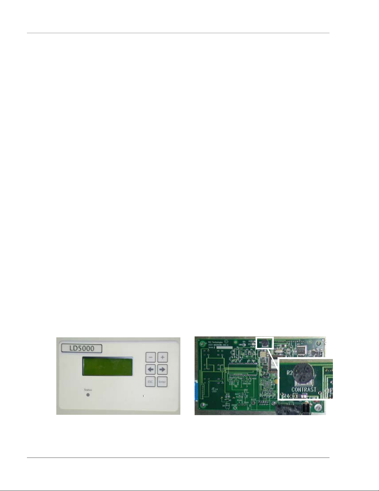
Figure 1-1 LD5000 LCD Interface Figure 1-2 R2 Contrast Adjustment
2 970.484.6510 www.rletech.com
Page 11
User Guide: LD5000 Chapter 1: Product Overview
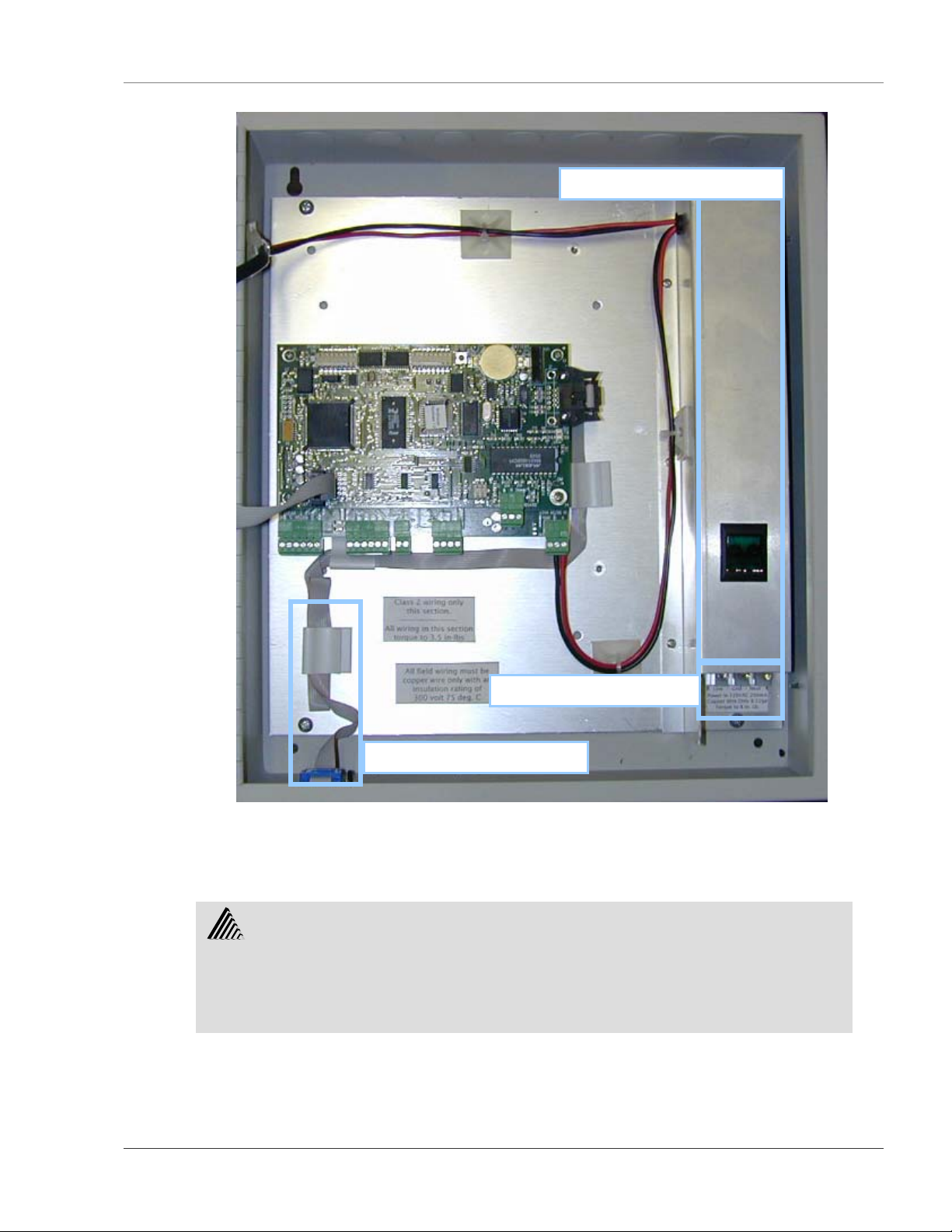
Power Supply & Power Switch
Power Input Terminal Block
RA-232 Serial Cable Interface
Figure 1-3 LD5000 Enclosure Interior
Warning!
• A dedicated circuit breaker must be provided in the building within
close proximity to the RLE unit and be clearly marked as the
disconnecting device for this unit.
www.rletech.com 970.484.6510 3
Page 12
Chapter 2: Connections and Settings User Guide: LD5000
play,
CHAPTER 2: CONNECTIONS AND SETTINGS
The LD5000 is comprised of three boards. All three boards are accessed when the device’s front cover is
opened. The display board is located on the inside of the door. The microprocessor board is stacked on top
of the leak detection board. Since the leak detection board is longer than the microprocessor board, the
connectors on the leak detection board extend past the end of the microprocessor board. These two boards
are secured to the inside of the unit.
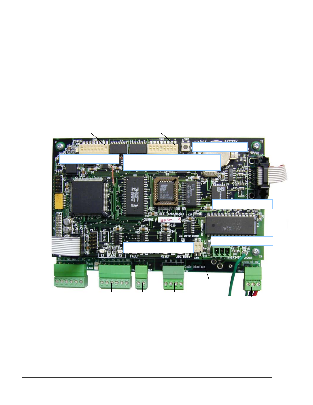
The connectors on the leak detection board, found at the bottom of the following photograph, are labeled
TB1 through TB5. The connectors on the microprocessor board are labeled TB1 and P3. The switches on
the microprocessor board are labeled SW1 through SW4.
Pin 1 Pin 1
–
–
-
SW2 – RS-485 and RS-232 Baud Rate,
Dis
and 4-20mA Output Settings
TB5 – Fault/Leak
Relay Outputs
TB4 – Fault/Leak
Relay Outputs
Figure 2-1 LD5000 Leak Detection Boards
SW4 – Termination Setting
TB3 –
4-20mA
Output
TB2 – Cable
Interface
Pin 1
–
-
–
-
TB1 – 24V
Input Power
4 970.484.6510 www.rletech.com
Page 13

User Guide: LD5000 Chapter 2: Connections and Settings
2-1 DISPLAY BOARD
2-1.1 R2: Contrast
This dial adjusts the 4x20 LCD’s contrast. Turn the knob clockwise or counterclockwise to adjust the
contrast as necessary.
2-2 LEAK DETECTION BOARD
2-2.1 TB1: Input Power
This is a factory wired three position connector with the following connections (for reference only):
TB1-1 ground
TB1-2 24VDC negative (-)
TB1-3 24VDC positive (+)
2-2.2 TB2: Cable Interface
The Water Leak Detection Cable connects to TB2. A fifteen foot Non-Sensing cable is provided to connect
the LD5000 to the Water Leak Detection Cable. Connect the cable wires to TB2 as follows:
TB2-1 White wire
TB2-2 Black wire
TB2-3 Green wire
TB2-4 Red wire
2-2.3 TB3: 4-20mA Output
A 4-20mA loop powered output is provided on TB3.
Four mA = no alarm
Five mA = leak at 0 distance
19mA = full scale distance specified by SW2 positions 6-8 (see page 14)
20mA = cable fault
Connect the 4-20mA wires to TB3 as follows:
TB3-1 4-20mA positive (+)
TB3-2 4-20mA negative (-)
2-2.4 TB4 & TB5: Relays
Terminals TB4 and TB5 are Form C Relay Outputs. Each terminal has two outputs. TB4 provides a
connection to one of the leak alarm relay outputs and one of the fault relay outputs; TB5 provides a second
set of contacts for the same leak and fault alarms.
The six contacts on TB4 and TB5 are labeled Leak NO, Leak C, Leak NC, Fault NO, Fault C, and Fault
NC. Connect the alarm relay wires to TB4 and TB5 as follows:
TB4-1 Leak alarm normally open (NO)
TB4-2 Leak alarm common (C)
TB4-3 Leak alarm normally closed (NC)
TB4-4 Fault alarm normally open (NO)
TB4-5 Fault alarm common (C)
TB4-6 Fault alarm normally closed (NC)
TB5-1 Leak alarm normally open (NO)
TB5-2 Leak alarm common (C)
www.rletech.com 970.484.6510 5
Page 14
Chapter 2: Connections and Settings User Guide: LD5000
TB5-3 Leak alarm normally closed (NC)
TB5-4 Fault alarm normally open (NO)
TB5-5 Fault alarm common (C)
TB5-6 Fault alarm normally closed (NC)
Two LEDs, labeled Fault and Leak, are located between TB4 and TB5. They indicate the status of the
relays. The leak detection relay is activated when a leak is detected. The cable break relay is activated
when a cable fault is detected.
Both relays can be configured to be unsupervised or supervised. If the relay is set to supervised, the relays
will be closed as long as no alarm condition exists. A leak, cable trouble, or power failure will cause the
appropriate relay to open.
The relays can also be configured to latched or unlatched. A latched alarm requires a manual reset of the
system once a leak or cable problem is no longer present.
2-3 MICROPROCESSOR BOARD
2-3.1 TB1: RS-485 Connector
TB1 connects the RS-485 network. A grounded shield contact is provided for connection to shielded cable.
If the shield contact is used, verify the power connector is properly grounded and there is no voltage
potential between units on the network. The RS-485 port is set to no parity, 8 databits, 1 stop bit (n, 8, 1).
Connect the RS-485 wires to TB1 on the top PC board as follows:
TB1-1 A (+)
TB1-2 B (-)
TB1-3 Shield
2-4 INPUT POWER
The LD5000 mounted in the metal enclosure requires an 85-264VAC connection (2 wire & ground).
Connect the 85-264VAC to the input terminal block. Connect the 85-264VAC to the input terminal block.
Warning!
Do not apply power until connections are complete.
2-5 POWER ON/OFF SWITCH
An internal power switch is used to power the unit on and off. This switch contains an integrated breaker
rated at two amps.
2-6 RS-232 CONNECTOR
The RS-232 port uses only the transmit, receive, and ground pins (2, 3 and 5). The manufacturer sets the
baud rate at 9600. The user may adjust the baud rate through SW2 on the microprocessor board. The RS232 port is set to no parity, 8 databits, 1 stop bit (n, 8, 1).A straight through cable should be used to connect
a terminal or PC to the LD5000.
6 970.484.6510 www.rletech.com
Page 15
User Guide: LD5000 Chapter 2: Connections and Settings
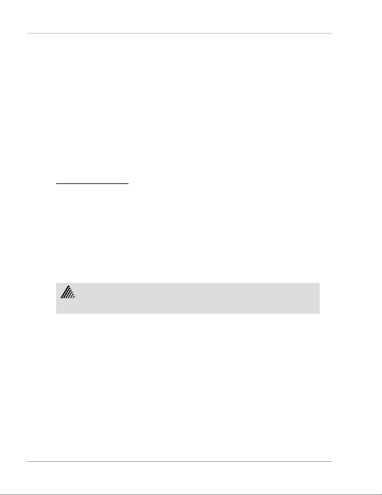
Figure 2-2 LD5000 Wiring Diagram
2-7 SWITCHES
2-7.1 SW1: Setting RS-485 Address
8 7 6 5 4 3 2 1
SW1, positions 1 through 8, are used to set the RS-485 address. The
address can range from 00000001 to 11111111.
2-7.2 SW2: Baud Rate Settings, LCD Display, 4-20mA Scale
8 7 6 5 4 3 2 1
For All SW Settings:
1 – Switch is on.
0 – Switch is off.
www.rletech.com 970.484.6510 7
Page 16

Chapter 2: Connections and Settings User Guide: LD5000
Baud rate settings for the RS-232 port and the RS-485 port are both set through this dip switch. The RS232 baud rate is set with switch positions 1 and 2. The RS-485 baud rate is set with switch positions 3 and
4.
2-7.2.1 SW2, Positions 1 & 2
The manufacturer sets the baud rate of the RS-232 connection to 9600 baud. Manipulating the positions of
switches 1 and 2 adjusts the baud rate as follows:
21
(Switch position)
01 = 1200
10 = 2400
00 = 9600
11 = 19,200
2-7.2.2 SW2, Positions 3 & 4
The manufacturer sets the baud rate of the RS-485 connection to 9600 baud. Users can set the baud rate
using SW2, positions 3 and 4, and manipulating them as follows:
43
(Switch position)
00 = 1200
10 = 9600
01 = 2400
11 = 19,200
2-7.2.3 SW2, Position 5
SW2, position 5 enables or disables the LCD.
0 = Disable
1 = Enable
2-7.2.4 SW2, Position 6-8
SW2, positions 6 through 8, designate the length of cable attached to the LD5000. This insures the 420mA output readings are correct for the LD5000 system. Without an accurate length setting, the unit
would not return the proper 4-20mA reading to diagnose the condition of the cable.
Switch settings are listed below. If the length of cable falls between two amounts, use the settings for the
higher of the two amounts:
876
(Switch position)
000 = 0 - 500 ft. (0 - 152.4 m)
001 = 0 - 1000 ft. (0 - 304.8 m)
010 = 0 - 1500 ft. (0 - 457.2 m )
011 = 0 - 2000 ft. (0 - 609.6 m)
100 = 0 - 2500 ft. (0 - 762.0 m)
101 = 0 - 3000 ft. (0 - 914.4 m)
110 = 0 - 4000 ft. (0 - 1219.2 m)
111 = 0 - 5000 ft. (0 - 1524.0 m)
2-7.3 SW4 - Termination Setting
SW4-1 is used to set termination on the unit. ON (down) indicates termination and OFF (up) indicates no
termination.
8 970.484.6510 www.rletech.com
Page 17
User Guide: LD5000 Chapter 3: Installation
CHAPTER 3: INSTALLATION
3-1 INSTALLING THE UNIT
The LD5000 is a wall mounted device. To secure the device to the wall, first remove the aluminum back
panel and all electronics from the enclosure. There are knockouts on the top and bottom of the enclosure
designed to accommodate .5” conduit. Remove as many as necessary. There are two holes in the top back
of the unit spaced 10.5” apart. Use drywall anchors to secure the unit to the wall. Put two more drywall
anchors through the two holes in the bottom back of the unit. Reinstall the back panel and reconnect the
electronics.
3-2 CONNECTING THE WATER LEAK DETECTION CABLE
The LD5000 is packaged with a 15’ length of leader cable. One end of this leader cable connects into the
LD5000. This end of the cable is finished with a terminal connector. The other end features a mating
connector which connects with the leak detection cable. The end of the cable is finished with a removable
end terminator.
Attach (clip) the plastic EMI Suppression core to the 15’ leader cable. The plastic core should slide freely
once it is placed on the cable. Make sure the core is located close to the end of the leader cable that
attaches to the LD5000 terminal block connection (TB2). Connect the 15' leader cable with the EMI
Suppression core to the LD5000; plug the terminal connector into the cable interface terminal block TB2.
From left to right, with the screws of the connector facing up, the wires that screw into the terminal
connector should be colored white, black, green, and red. If the terminal connector is removed from the
end of the cable, make sure the wires are in this same order when the connector is reapplied.
Once the leader cable is plugged into the terminal blocks, it is ready to be connected to the leak detection
cable. To do this, unscrew the end terminator from the end of the leader cable. Attach the first length of
water leak detection cable to the leader cable. Route the water leak detection cable according to the cable
layout diagram, if provided. Lay the cable according to the following guidelines. Secure the end
terminator on the unoccupied end of the leak detection cable.
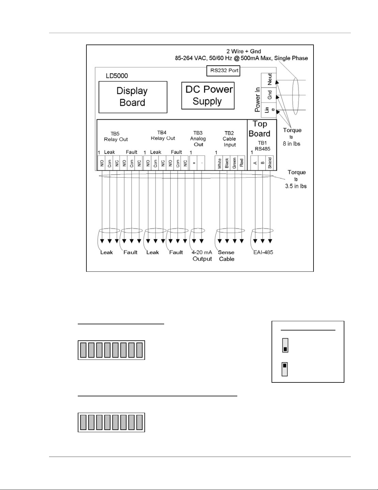
Figure 3-1 Water Leak Detection Cable
3-2.1 Securing Cable to the Floor
Secure the cable to the floor with either J-clips or one of the other approved methods shown in Figure 3-2
Cable Installation Methods. J-clips are the manufacturer’s recommended installation method and can be
installed as follows:
• Place one J-clip every three feet along the length of the water leak detection cable and one at each
turn of the cable.
www.rletech.com 970.484.6510 9
Page 18
Chapter 3: Installation User Guide: LD5000
• If the cable is installed over an obstruction, clip the cable on both sides, as close to the obstruction
as possible.
• Do not install the cable directly in front of an air conditioner. Allow a minimum of six feet
between the unit and the cable. If the cable is too close to the air conditioning unit’s air stream, the
moisture from the humidifier may cause false leak readings. If the cable must be installed in front
of an air conditioning unit, place the J-clips 12 to 18 inches apart.
NOTE:
3-2.1.1 Recommended Cable Installation
It is important to finish the end of the leak detection cable with the end
terminator. If the end terminator is not present, a cable fault will register.
Note any variances between the cable layout diagram and the actual cable
installation.
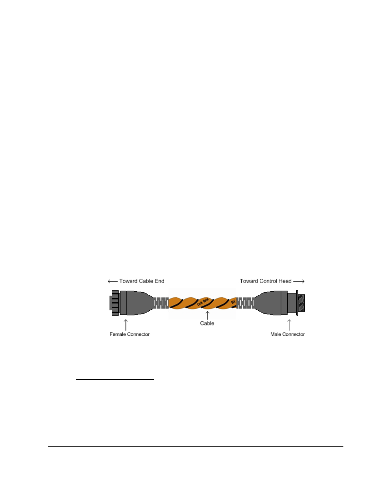
Laid freely on the floor.
Only recommended in
spaces with no access.
Secured to floor with J-clips.
Secured to floor with mastic. Installed in protective covering.
Secured to floor with tie wrap.
Figure 3-2 Cable Installation Methods
Secured to pedestal with tie wrap.
Do Not Secure as Shown
10 970.484.6510 www.rletech.com
Page 19

User Guide: LD5000 Chapter 3: Installation
3-3 APPLY POWER TO THE UNIT
Once the leak detection cable is connected to the unit, power may be applied.
Warning!
• A dedicated circuit breaker must be provided in the building within
close proximity to the RLE unit and be clearly marked as the
disconnecting device for this unit.
The LD5000 operates on 85-264VAC power. An AC power supply should be run to the location of the
unit. Before applying power to the unit, make sure the AC breaker switch is turned off.
Once the power is turned off, strip the end of the AC supply so the three wires inside are exposed. Strip the
end of each of the three wires and feed the end of the power supply into the LD5000 enclosure. The three
wires must now be inserted into the terminal block in the lower right corner of the enclosure. As is labeled
in the enclosure, the live power line is placed inside the left hand opening of the terminal block. The Earth
ground line is placed into the terminal block’s center station. The neutral line is placed into the opening on
the right side of the terminal block.
Once all the wires are placed inside the terminal block, tighten the three screws across the bottom of the
terminal block until the wires are securely held in place. Turn the AC supply back on. Flip the LD5000’s
power switch on to activate the unit. Wait approximately one minute. No alarm should be present.
On the LCD, enter the Status menu. Press Enter (↵) twice. The cable length is displayed. If this reading
varies by more than ±5% of the actual length of cable installed, verify the installation.
Use the switch settings on page 8 to set the cable length scale for the analog 4-20mA loop. Set the clock,
system name, relay configuration, feet/meters, LCD setup (re-alarm time, password), etc.
Wait at least 30 minutes before calibrating the LD5000. Calibrate the LD5000 through the front panel
Setup Menu (page 14) or through the RS-232 configuration port System Configuration Menu (page 33).
Auto calibration is recommended.
Map the cable per the instructions in Chapter 8: Mapping the Cable beginning on page 21.
www.rletech.com 970.484.6510 11
Page 20
Chapter 4: 4-20MA output testing User Guide: LD5000
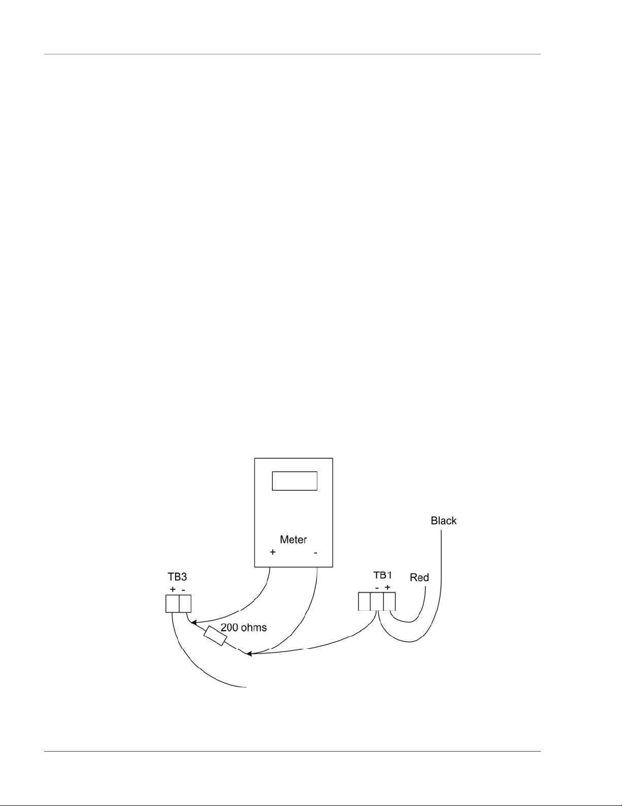
CHAPTER 4: 4-20MA OUTPUT TESTING
The LD5000’s 4-20mA output is loop powered and tested by the manufacturer. The manufacturer
guarantees its performance upon delivery. Should the 4-20mA output need to be tested in the field, follow
these steps. The following procedure is performed with the cable connected, unless otherwise indicated.
1. Remove the two position plug from TB3.
2. Remove any wires from the terminal and install a 200Ohm resistor to TB3-2. Then apply
+24V to TB3-1 and ground of the 24V supply to the other side of the resistor.
3. Reinstall the plug on TB3.
4. With the system on and no alarms present, measure the DC voltage across the resistor. A
value of 0.8VDC should register. This equates to 4mA, or normal operation.
5. Remove the water leak detection cable and wait for the unit to activate its cable trouble alarm.
Measure the DC voltage across the resistor. A value of approximately 4.0VDC should be
measured. This equates to 20mA, or a fault alarm. Reconnect the water leak detection cable.
6. Place water on the end of the water leak detection cable. Measure the DC voltage across the
resistor. The value will be proportional to the length of cable set on the dip switches. A value
of approximately 3.8V, which equates to 19mA, will be read if the length of the cable is
identical to the length set by the switches. Dry the cable.
7. Place water on the start of the cable. Measure the DC voltage across the resistor. A
measurement of approximately 1.2VDC, or 5mA, should be measured. This corresponds to a
leak at zero distance. Dry the cable.
8. Remove the resistor from the plug and reattach any wires as necessary.
Figure 4-1 4-20mA Testing
12 970.484.6510 www.rletech.com
Page 21
User Guide: LD5000 Chapter 5: LCD Default Display
S
CHAPTER 5: LCD DEFAULT DISPLAY
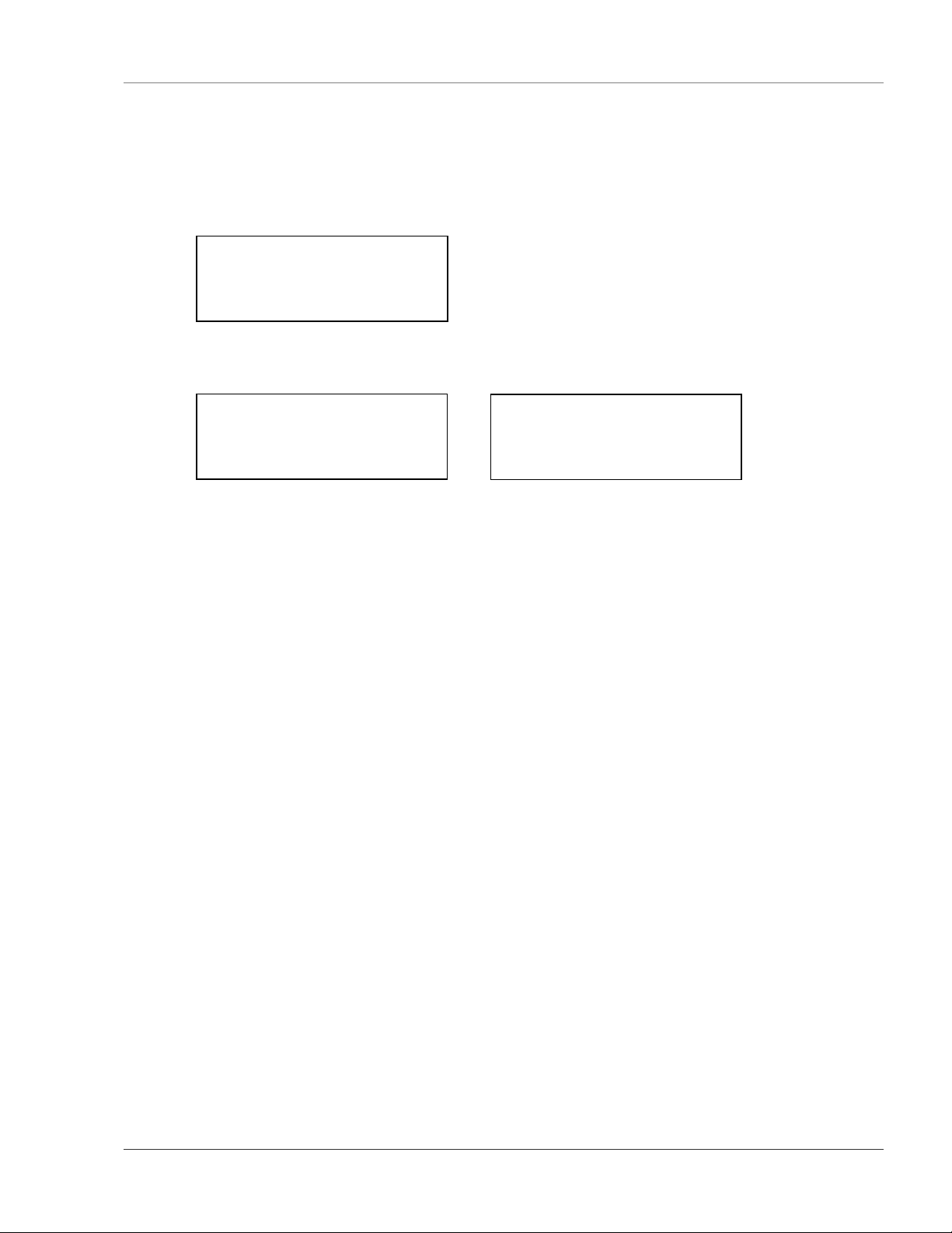
When the LD5000 is powered up, diagnostics are performed. The boot ROM and flash program code are
verified. While these diagnostics are being performed, the following text is displayed on the LCD:
****** LD5000 ******
* RLE Technologies *
** Copyright 2000 **
************************
Once the diagnostics are complete, the LCD alternates between the following panels:
** LD5000 Display **
* RLE Technologies *
* Copyright 1999 *
01/10/01 09:44:32
Any time a screen within the LCD interface is left idle for more than one minute, it will return to this
default display.
ystem Status:
Normal
Press a Key For Menu
www.rletech.com 970.484.6510 13
Page 22
Chapter 6: LCD Main Menu User Guide: LD5000
CHAPTER 6: LCD MAIN MENU
A limited selection of system set-up, configuration, and display functions begin in the Main Menu. For a
more comprehensive selection of functions, use the RS-232 interface.
The LCD is accompanied by a six button control panel. The - (minus) and + (plus) keys are used to
decrease and increase values on the display. The left and right arrow keys are used to move the cursor
through the display. The Esc key backs the display up one menu level at a time. The Enter (↵) key selects
an option and commits changes.
From the Main Menu, use the left and right arrow keys to position the arrow on the LCD in front of the
appropriate menu choice. Press the Enter (↵) key to select the option.
*** Main Menu ***
->Status Setup
Log/Data System
Reset Comms
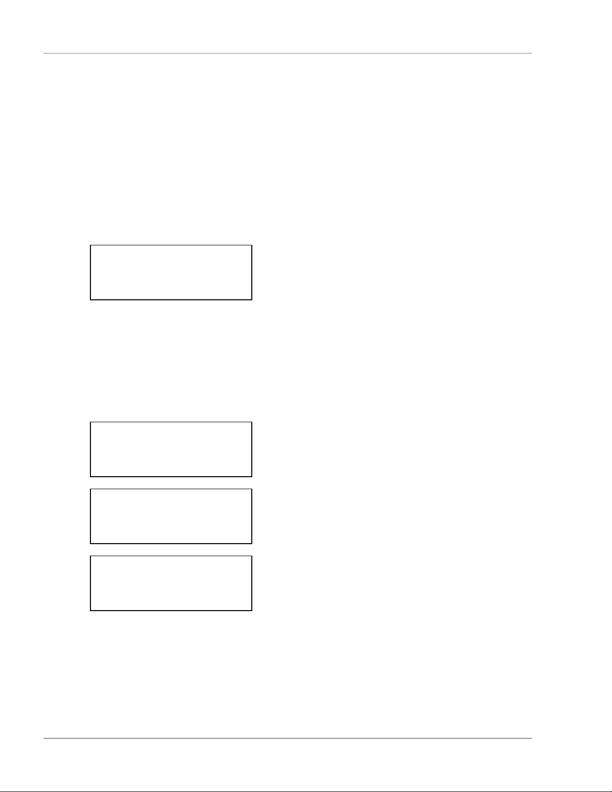
6-1 STATUS OPTION
The Status option displays the Cable Status Screens. The first screen of this option shows the current
status of the cable. The second screen, accessed by pushing the Enter (↵) key when the cursor is next to
the down option, displays the length of the cable monitored by the LD5000 and the leakage current on the
cable. A threshold for the current reading can be set through the TripPoints option in the Setup Menu.
This will help avoid false leak readings due to cable contamination. Press the Esc key to exit the cable
status screen and return to the Main Menu.
** Cable Status **
System Normal
->Down
** Cable Status **
Length: 300ft
Current: 0 uA
Up ->Down
** Cable Status **
Contam Dly: 0/120
Leak Delay: 0/20
->Up
6-2 SETUP MENU
The Setup option displays the password protected Setup Menu. Use the - (minus) and + (plus) keys to enter
the correct numerical values. Use the right and left arrow keys to move to the next position in the
password sequence. Press the Enter (↵) when the password is correct. The manufacturer’s default
password for this menu is 1234. To disable this feature, enter 0000 as the password in the Calibration
Menu section of the RS-232 interface.
14 970.484.6510 www.rletech.com
Page 23
User Guide: LD5000 Chapter 6: LCD Main Menu
T
T
A
A
E
The Setup Menu allows authorized users to configure the LD5000’s settings. This menu is described in
greater detail in Chapter 7: LCD Setup Menu. Press the Esc key to exit the Setup Menu and return to the
Main Menu.
nter Password:
0000
^
** Setup Menu **
->TripPoints Clock
Re-Alarm Ft/M
Calibrate FcDft
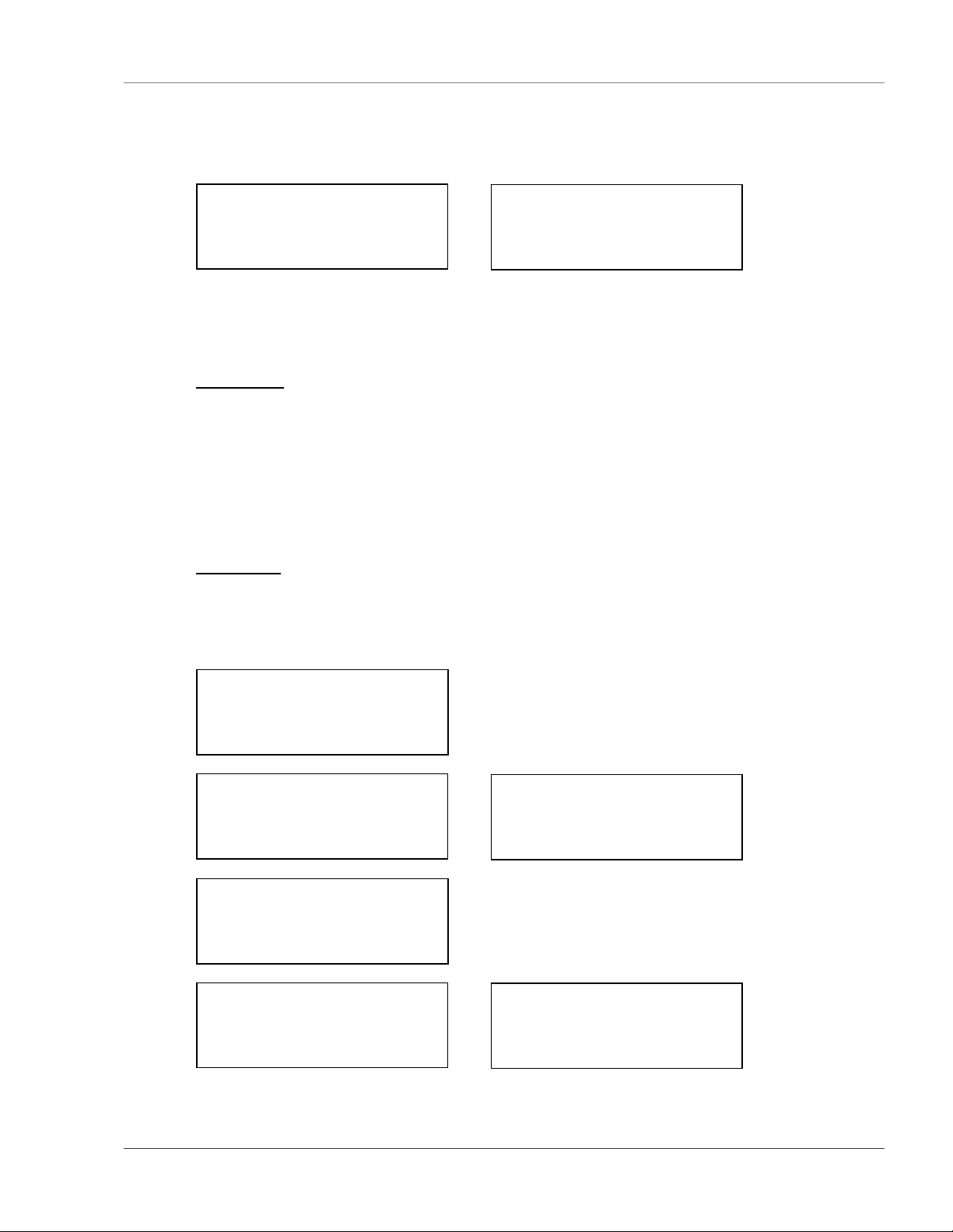
6-3 LOG/DATA
The Log/Data option displays the Log/Data Menu. This menu provides a view of the History Log and the
Trend Data and an option to clear both the History Log and the compiled Trend Data.
6-3.1 History Log
The History Log displays the most recent 100 events recorded by the unit. Events are displayed in the
following manner: Number-Status-Description
Date Time whereas:
Number is a sequential event number assigned to the event.
Status is R = Returned to normal, A = Alarm, or F = Forced to Normal.
Description is a detail of the nature of the event.
Date is the date the event occurred.
Time is the time at which the event occurred.
6-3.2 Trend Data
The Trend Data displays the leakage current on the cable. One measurement is taken at the user set interval
(1 min - 1440 min; factory default is 1440 min (1day)). The log retains the 288 most recent entries.
Analyzing the Trend Data can help determine the location of long term contamination build up
(degradation), etc. on the cable. Press the Esc key to exit the Log/Data Menu and return to the Main Menu.
** Log/Data Menu **
-> History Trend
HistClr TrendClr
TrndIntv
larm Log: 23/23
023-R-System Booted
01/10/01 09:54:11
->Down Up
** Log/Data Menu **
History ->Trend
HistClr TrendClr
->Up
rend Data: 1/4
TD001-Leakage=0uA
01/10/01 16:02:56
Down ->Up
larm Log: 21/23
021-A-Leak @ 55ft
01/10/01 10:15:27
Down ->Up
rend Data: 2/4
TD002-Leakage=0uA
01/11/01 16:02:56
Down ->Up
www.rletech.com 970.484.6510 15
Page 24
Chapter 6: LCD Main Menu User Guide: LD5000
M
M
M
M
C
C
T
T
rend Data: 3/4
TD003-Leakage=0uA
01/12/01 16:02:57
Down ->Up
lear the Alarm Log?
Accept -> Cancel
odify Trend
Interval
1440 Minutes
+/- then (Enter)
6-4 SYSTEM
The System option displays the System Menu. This menu allows a user to map the water leak detection
cable that is attached to the LD5000. Mapping the cable is a key step in pinpointing a leak. Cable should
not be mapped until it is properly installed in its intended area, and the system is calibrated for the length of
cable installed. Whenever additions or adjustments are made to the water leak detection cable, the cable
should be remapped.
6-4.1 ViewMap
The ViewMap option allows the user to view the current system map.
rend Data: 4/4
TD004-Leakage=0uA
01/12/01 16:02:56
Down ->Up
lear the Trend Log?
Accept -> Cancel
6-4.2 StartMap
The StartMap option begins the mapping process:
For a complete set of LCD interface cable mapping instructions, refer to Chapter 8: Mapping the Cable.
Press the Esc key to exit and return to the Main Menu.
** System Menu **
->ViewMap StartMap
apping Data: 1/6
Pnt#1 Dist=68ft
Pnt#2 Dist=176ft
->Up
apping Data: 5/6
Pnt#5 Dist=494ft
Pnt#6 Dist=675ft
->Down
apping Data: 3/6
Pnt#3 Dist=247ft
Pnt#4 Dist=378ft
->Down ->Up
16 970.484.6510 www.rletech.com
Page 25
User Guide: LD5000 Chapter 6: LCD Main Menu
M
** System Menu **
ViewMap ->StartMap
** System Menu **
Begin Mapping Mode?
Mapping Mode On
Press any key to
End Mapping Mode
6-5 RESET MENU
The Reset option displays the Reset Menu. This menu allows the operator to reset the system, reset individual relay outputs and update alarms.
** Reset Menu **
->Reset ->Update
Fault Rly Leak Rly
6-5.1 Leak Rly
This command silences the leak relay output. A new leak will retrigger this alarm.
6-5.2 Fault Rly
This command silences the fault relay output. A new cable fault will retrigger this alarm.
6-5.3 Reset
This command forces all alarms off. If an alarm condition is still present after the Reset command is
executed, the alarm is reactivated. However, it will not be reentered in the Alarm History Log.
6-5.4 Update
This command updates and resets all alarms. This command forces all alarms off. If an alarm condition is
still present after the Update command is executed, the alarm is reactivated and another entry is made in the
Alarm History Log.
6-6 COMMS COMMAND
This command displays Modbus information like the address, baud rate, and other statistics. The
information can be reset by pressing Enter (↵). Press Esc to exit.
odbus Adr:001 600
4in: 0 Out: 0
Min: 0 Out: 0
->Reset
www.rletech.com 970.484.6510 17
Page 26
Chapter 7: LCD Setup Menu User Guide: LD5000
S
M
M
M
M
CHAPTER 7: LCD SETUP MENU
The Setup Menu allows authorized users to adjust the LD5000’s settings. Each menu option displays a
different adjustable parameter. Press Esc to exit the Setup Menu and return to the Main Menu.
** Setup Menu **
->TripPoints Clock
Re-Alarm Ft/M
Calibrate FcDft
7-1 TRIPPOINTS
The TripPoints option allows users to modify the detection and contamination trip points for the LD5000.
These trip points help the system avoid false alarm readings. Throughout this menu, the user can also set
the leak alarm and contamination alarm delays (20 to 3600 seconds). Press Esc to exit the TripPoint Menu
and return to the Setup Menu.
** TripPoint Menu **
->Leak LeakDelay
Contam ContDelay
odify Detection
TripPoint: 150 uA
odify Leak Alarm
Delay:
20 Seconds
+/- then (Enter)
** TripPoint Menu **
Leak LeakDelay
->Contam ContDelay
odify Contamination
TripPoint: 050 uA
odify Contamination
Alarm Delay:
120 Seconds
+/- then (Enter)
7-2 CLOCK OPTION
The Clock option allows users to modify the LD5000’s date and time settings. Press Esc to exit the Set
Clock function and return to the Setup Menu.
et Clock:
01/10/01 10:51
^ ^
7-3 RE-ALARM
The Re-Alarm option allows users to determine the number of minutes between annunciations of the same
alarm. Enter 000 to disable this feature. Factory default is “0” (disabled). Press Esc to exit and return to
the Setup Menu.
18 970.484.6510 www.rletech.com
Page 27
User Guide: LD5000 Chapter 7: LCD Setup Menu
C
C
S
E
E
C
L
E
nter Realarm (Min):
000
^
7-4 FT/M FUNCTION
The Ft/M function designates whether the unit’s distance readings are displayed in feet or meters. Press
Esc to exit and return to the Setup Menu.
elect Feet / Meters
->Feet Meter
7-5 CALIBRATE
The Calibrate option allows users to manually input the number of feet of cable connected to the LD5000.
This automatically calibrates the system to the cable length entered. Enter the exact cable length attached
to the system to ensure accurate calibration. Press the Esc key to exit and return to the Setup Menu.
NOTE
nter Cable Length:
^^
Range (901-1101)
1000ft
able Auto Calibrate
Step 1 of 4
able Auto Calibrate
:
Step 2 of 4
It may be necessary to restore the system to factory defaults before
calibrating, or if the following error message is received on the LCD display:
“Error Length Not in Range Press Any Key To Return”
eak Detected Alarm
Can’t Calibrate
Press Any Key
To Return
rror
Length Not In Range
Press Any Key
To Return
able Break Alarm
Can’t Calibrate
Press Any Key
To Return
www.rletech.com 970.484.6510 19
Page 28
Chapter 7: LCD Setup Menu User Guide: LD5000
C
C
E
R
able Auto Calibrate
:
Step 3 of 4
****** LD5000 ******
* RLE Technologies *
** Copyright 2000 **
************************
able Auto Calibrate:
Step 4 of 4
Cable Auto Cal Done
Saving Changes. .
7-6 FCDFT OPTION
The FCDFT option will allow the user to restore the LD5000 to factory calibration default settings.
estore Factory
Defaults?
->Accept Cancel
rasing Data . .
Writing Data . .
Done, Press any key
to continue
20 970.484.6510 www.rletech.com
Page 29

User Guide: LD5000 Chapter 8: Mapping the Cable
y
CHAPTER 8: MAPPING THE CABLE
After the water leak detection cable is laid in the desired configuration, the cable can be mapped. Mapping
the cable improves the accuracy of the LD5000 and makes it easier to locate a leak.
The LD5000 computes the distance from the control panel to the leak along the length of water leak
detection cable attached to the unit. In most cases, the water leak detection cable is laid in a curved or
serpentine pattern. This may make it difficult to locate a leak when given a linear distance. To help
alleviate this problem, identify a series of easily accessible, evenly spaced points along the cable length.
Number the points, and record their locations on the leak detection reference map. Refer to the directions
below and use the numbered points to map the cable. Then, when the unit detects a leak, the location of the
leak can be determined by comparing the distance shown on the control panel with the known positions
along the cable as recorded on the reference map.
NOTE
The system must be calibrated prior to mapping.
8-1 MAPPING DIRECTIONS
1) If a reference is not provided by RLE Technologies, create a drawing that represents the floor
plan. This drawing must include the room layout (walls, doors, and other permanent structures),
the water leak detection cable routing path and any jumper sections of non-sensing cable.
2) Physically identify points along the cable routing path. The points should be easily accessible and
evenly spaced. Number the points and record their location on the reference map.
3) Using the front panel of the LD5000:
• Select System and press Enter (↵).
• Select StartMap and press Enter (↵).
• Select Accept to start mapping and press Enter (↵).
4) To test, wrap a damp paper towel or sponge around the cable at one of the previously mapped
points. The LD5000 produces a short beep within approximately 30 seconds. The LCD displays
the LD5000’s calculated distance to the leak. Remove the paper towel and dry the cable. Within
approximately 20 seconds, the LD5000 produces a long beep indicating the short is removed and
the system has returned to normal.
TIP
If the individual mapping the cable is not in a position to hear the
audible alarm, wait two minutes between each point. This ensures the
s
stem has had time to stabilizer.
5) Go to the next point and repeat the above steps until all points along the cable are mapped and
tested.
6) When mapping is complete, press any key on the LD5000 to exit the mapping mode. This
LD5000 displays Mapping Mode Off. Press any key again to save the map and return to the
System Menu.
www.rletech.com 970.484.6510 21
Page 30

Chapter 8: Mapping the Cable User Guide: LD5000
g
7) Select ViewMap on the LCD and record the LD5000’s reading next to each point on the reference
map.
8) Mount the leak detection reference map alongside to the LD5000 control panel or the remote
display. When a leak or cable break occurs, refer to the map and the distance displayed on the
LD5000 to determine the physical location of the leak.
Warning!
Loss of power will cause all mappin
data to be lost.
22 970.484.6510 www.rletech.com
Page 31

User Guide: LD5000 Chapter 9: RS-232 Interface Startup
CHAPTER 9: RS-232 INTERFACE STARTUP
Make sure the RS-232 port is connected to a PC or terminal with a straight through cable (see section 2-6
RS-232 Connector on page 6). Run terminal emulation software and make sure the settings match the
LD5000 RS-232 port configuration. When the LD5000 is powered up, diagnostics are performed. The
boot ROM and flash program code are verified. Output similar to the screen displayed below should
appear on the terminal or terminal emulation software. Once the system reaches this point, press the Enter
(↵) key to display the Main Menu.
RLEbh Firmware V1.1 BOOTUP - THU 03/06/03 10:58:24
uP last reset by: external signal
Diagnostics in progress
Serials: Passed
Ram: Passed
Clock: Passed
VPP = 5.04 Passed
Flash Blank Check:
Parm1= Has Data
Parm2= Has Data
Prgm = Has Data
Prgm Flash checksum: 6C32/6C32 Valid
Power Supplies:
24V: 22.66
15V: 15.17
Passed
Flash Code will start in 5 seconds
Press any key to abort Flash Code
LD5000 V2.3 B0 03/06/03
SYSTEM BOOTED @ 03/06/03 10:58:32
Copyright 2003, Raymond & Lae Engineering Inc.
Loading Block 2
DATA LOADED
LD5000 Diagnostics
Initializing Cable ADC: Passed
<LD5000>
www.rletech.com 970.484.6510 23
Page 32

Chapter 10: RS-232 Main Menu User Guide: LD5000
CHAPTER 10: RS-232 MAIN MENU
Once the startup processes are complete, press the Enter (↵) key to access the Main Menu. All system setup, configuration, and display functions begin in the Main Menu. Two letter commands display
information requested, execute commands selected, and display submenus for additional inquiry and
system configuration functions.
** LD5000 Help **
SC - LD5000 System Configuration
LS - Leak Status
SL - Silence Leak Relay
SF - Silence Fault Relay
SR - Silence All Relays
CA - Current Alarms
RA - Reset Alarms
UP - Update Alarms
AS - Alarm Silence (LCD)
AH - Alarm History
CH - Clear Alarm History
TD - Trend Data Table (Leakage Current)
CT - Clear Trend Data Table
TI - Display Date/Time
NS - Network Status (RS-485)
MR - Reset Modbus Status (RS-485)
ND - Network Display (RS-485)
MT - Modbus Display
EX - Exit
10-1 FUNCTION COMMANDS
Once the startup processes are complete, press the Enter (↵) key to access the Main Menu. All system setup, configuration, and display functions begin in the Main Menu. Two letter commands display
information requested, execute commands selected, and display submenus for additional inquiry and
system configuration functions. These commands include:
10-1.1 SC - System Configuration
SC displays a submenu that lists all items in the System Configuration Menu. System Configuration
options are discussed in further detail starting on page 33.
10-1.2 LS - Leak Status
LS displays the current leak cable status.
10-1.3 SL - Silence Leak Relay
SL silences the leak relay output. A new leak will re-trigger this alarm.
10-1.4 SF - Silence Fault Relay
SF silences the fault relay output. A new cable fault will re-trigger this alarm.
10-1.5 SR - Silence All Relays
SR silences all relay outputs.
10-1.6 CA - Current Alarms
CA displays all active alarms present on the unit.
24 970.484.6510 www.rletech.com
Page 33

User Guide: LD5000 Chapter 10: RS-232 Main Menu
10-1.7 RA - Reset Alarms
RA resets all alarm relays. This command forces all alarms off. If an alarm condition is still present after
the RA command is executed, the alarm is reactivated. If an alarm is still active after the RA command is
executed, it will not be reentered in the Alarm History Log.
10-1.8 UP - Update Alarms
UP updates and resets all alarms. This command forces all alarms off. If an alarm condition is still present
after the UP command is executed, the alarm is reactivated and another entry is made in the Alarm History
Log.
10-1.9 AS - Alarm Silence sundry
AS silences the audible alarm on the LCD.
10-1.10 AH - Alarm History
AH displays the Alarm History Log.
10-1.11 CH - Clear Alarm History
CH clears the Alarm History Log.
10-1.12 TD - Trend Data Table
TD displays the Trend Data Table, which monitors and displays leakage current.
10-1.13 CT - Clear Trend Data Table
CT clears all records from the Trend Data Table.
10-1.14 TI - Display Date/Time
TI displays the LD5000’s current date and time.
10-1.15 NS - Network Status (RS-485)
NS displays the unit’s RS-485 network connection status.
10-1.16 MR - Reset Modbus Status
MR clears all the RS-485/Modbus counters.
10-1.17 ND - Network Display (RS-485)
ND displays the network diagnostics and all commands, requests, and data associated with them. This
feature is usually used by a service technician.
10-1.18 MT - Modbus Display
MT displays the Modbus packets.
10-1.19 EX - Exit
EX is used to enter the Bootloader command section. The unit will stop monitoring cable and allow
firmware updates to be loaded. To restore normal operation after updating firmware, type RUN and press
the Enter (↵) key on the keyboard, or power the unit off and then back on again.
www.rletech.com 970.484.6510 25
Page 34

Chapter 10: RS-232 Main Menu User Guide: LD5000
Warning!
• The Bootloader section is designed for experienced technicians or
users responsible for maintaining the system. Exit immediately if you
are not trained in the use of the Bootloader commands.
• Contact the manufacturer for more information regarding the
commands in this section.
26 970.484.6510 www.rletech.com
Page 35

User Guide: LD5000 Chapter 11: RS-232 Function Commands
CHAPTER 11: RS-232 FUNCTION COMMANDS
11-1 SC - SYSTEM CONFIGURATION
Please see page 33 for more information about System Configuration options.
11-2 LS - LEAK STATUS
Menu selection LS displays the current leak status.
** LD5000 Help **
SC – LD5000 System Configuration
LS - Leak Status
SL - Silence Leak Relay
SF - Silence Fault Relay
SR - Silence All Relays
CA - Current Alarms
RA - Reset Alarms
UP - Update Alarms
AS - Alarm Silence (LCD)
AH - Alarm History
CH - Clear Alarm History
TD - Trend Data Table (Leakage Current)
CT - Clear Trend Data Table
TI - Display Date/Time
NS - Network Status (RS-485/Modbus)
MR - Reset Modbus Status (RS-485)
ND - Network Display (RS-485)
MT - Modbus Display
EX - Exit
LS
Cable Length: 4995ft
Sense Cable Current: 0uA
No Leak!
<LD5000>
11-3 CA - CURRENT ALARMS
Menu selection CA displays the current alarm status.
** LD5000 Help **
SC – LD5000 System Configuration
LS - Leak Status
SL - Silence Leak Relay
SF - Silence Fault Relay
SR - Silence All Relays
CA - Current Alarms
RA - Reset Alarms
UP - Update Alarms
AS - Alarm Silence (LCD)
AH - Alarm History
CH - Clear Alarm History
TD - Trend Data Table (Leakage Current)
CT - Clear Trend Data Table
TI - Display Date/Time
NS - Network Status (RS-485/Modbus)
MR - Reset Modbus Status (RS-485)
ND - Network Display (RS-485)
MT - Modbus Display
EX - Exit
CA
LD5000
03/14/05 14:02:30 Leak Detected at 701ft
<LD5000>
www.rletech.com 970.484.6510 27
Page 36

Chapter 11: RS-232 Function Commands User Guide: LD5000
11-4 AH - ALARM HISTORY
Menu selection AH displays the alarm history log of the last 512 events. The oldest alarm is listed at the
top of the list. The most recent alarm is listed at the bottom of the list.
** LD5000 Help **
SC – LD5000 System Configuration
LS - Leak Status
SL - Silence Leak Relay
SF - Silence Fault Relay
SR - Silence All Relays
CA - Current Alarms
RA - Reset Alarms
UP - Update Alarms
AS - Alarm Silence (LCD)
AH - Alarm History
CH - Clear Alarm History
TD - Trend Data Table (Leakage Current)
CT - Clear Trend Data Table
TI - Display Date/Time
NS - Network Status (RS-485/Modbus)
MR - Reset Modbus Status (RS-485)
ND - Network Display (RS-485)
MT - Modbus Display
EX - Exit
*Note: The Alarm History Log displayed above has been shortened for the purpose of this user guide.
*AH
Alarm History Entries = 512
AH059-04-ALM -03/14/03 11:35:42 Zone 1: Leak Detected at 3575ft
AH060-04-RTN -03/14/03 11:36:14 Zone 1: No Leak
AH061-04-ALM -03/14/03 11:37:05 Zone 1: Leak Detected at 4648ft
AH062-04-RTN -03/14/03 11:37:37 Zone 1: No Leak
AH063-04-ALM -03/14/03 11:38:17 Zone 1: Leak Detected at 5003ft
AH064-04-RTN -03/14/03 11:38:49 Zone 1: No Leak
AH065-07-RTN -03/14/03 11:55:54 System Booted
AH066-04-ALM -03/14/03 12:00:46 Zone 1: Leak Detected at 254ft
AH067-04-RTN -03/14/03 12:02:05 Zone 1: No Leak
AH068-07-RTN -03/14/03 12:02:36 System Booted
AH069-03-ALM -03/14/03 12:59:54 Zone 1: Cable Fault
AH070-03-RTN -03/14/03 13:00:11 Zone 1: Cable Fault
AH071-04-ALM -03/14/03 13:01:31 Zone 1: Leak Detected at 1ft
AH072-04-RTN -03/14/03 13:02:03 Zone 1: No Leak
AH073-04-ALM -03/14/03 13:03:38 Zone 1: Leak Detected at 348ft
AH074-04-RTN -03/14/03 13:04:10 Zone 1: No Leak
AH075-04-ALM -03/14/03 13:04:45 Zone 1: Leak Detected at 700ft
AH076-04-RTN -03/14/03 13:10:46 Zone 1: No Leak
AH077-04-ALM -03/14/03 13:11:21 Zone 1: Leak Detected at 1054ft
AH078-04-RTN -03/14/03 13:12:40 Zone 1: No Leak
<LD5000>
28 970.484.6510 www.rletech.com
Page 37

User Guide: LD5000 Chapter 11: RS-232 Function Commands
11-5 CH - CLEAR ALARM HISTORY
Menu selection CH clears the alarm history log. Type Yes, Y, or y to clear the log. Type No, N, or n to
exit this option without clearing the log.
** LD5000 Help **
SC – LD5000 System Configuration
LS - Leak Status
SL - Silence Leak Relay
SF - Silence Fault Relay
SR - Silence All Relays
CA - Current Alarms
RA - Reset Alarms
UP - Update Alarms
AS - Alarm Silence (LCD)
AH - Alarm History
CH - Clear Alarm History
TD - Trend Data Table (Leakage Current)
CT - Clear Trend Data Table
TI - Display Date/Time
NS - Network Status (RS-485/Modbus)
MR - Reset Modbus Status (RS-485)
ND - Network Display (RS-485)
MT - Modbus Display
EX - Exit
CH
Are you sure (yes or no)? >y
ok
11-6 TD - TREND DATA TABLE (LEAKAGE CURRENT)
Menu selection TD displays the trend log data for the cable (leakage current). Data is logged by the trend
interval set by the user (default is 24 hours). The oldest trend entry is listed first. The most recent trend
entry is listed last. Analyzing the Trend data can help determine the location of long term contamination
build up (degradation), etc. on the cable.
** LD5000 Help **
SC – LD5000 System Configuration
LS - Leak Status
SL - Silence Leak Relay
SF - Silence Fault Relay
SR - Silence All Relays
CA - Current Alarms
RA - Reset Alarms
UP - Update Alarms
AS - Alarm Silence (LCD)
AH - Alarm History
CH - Clear Alarm History
TD - Trend Data Table (Leakage Current)
CT - Clear Trend Data Table
TI - Display Date/Time
NS - Network Status (RS-485/Modbus)
MR - Reset Modbus Status (RS-485)
ND - Network Display (RS-485)
MT - Modbus Display
EX - Exit
TD1
Cable Leakage Current Trend Data Table Entries = 3
TD001-03/06/03 15:37:31 Leakage=0uA
TD002-03/07/03 15:37:28 Leakage=0uA
TD003-03/08/03 15:37:30 Leakage=0uA
<LD5000>
www.rletech.com 970.484.6510 29
Page 38

Chapter 11: RS-232 Function Commands User Guide: LD5000
11-7 CT - CLEAR TREND DATA TABLE
Menu selection CT clears the trend data table. Type Yes, Y, or y to clear the data. Type No, N, or n to exit
this option without clearing the table.
** LD5000 Help **
SC – LD5000 System Configuration
LS - Leak Status
SL - Silence Leak Relay
SF - Silence Fault Relay
SR - Silence All Relays
CA - Current Alarms
RA - Reset Alarms
UP - Update Alarms
AS - Alarm Silence (LCD)
AH - Alarm History
CH - Clear Alarm History
TD - Trend Data Table (Leakage Current)
CT - Clear Trend Data Table
TI - Display Date/Time
NS - Network Status (RS-485/Modbus)
MR - Reset Modbus Status (RS-485)
ND - Network Display (RS-485)
MT - Modbus Display
EX - Exit
CT
Are you sure (yes or no)? >y
ok
11-8 TI - DISPLAY DATE/TIME
Menu selection TI displays the date and time as measured by the LD5000.
** LD5000 Help **
SC – LD5000 System Configuration
LS - Leak Status
SL - Silence Leak Relay
SF - Silence Fault Relay
SR - Silence All Relays
CA - Current Alarms
RA - Reset Alarms
UP - Update Alarms
AS - Alarm Silence (LCD)
AH - Alarm History
CH - Clear Alarm History
TD - Trend Data Table (Leakage Current)
CT - Clear Trend Data Table
TI - Display Date/Time
NS - Network Status (RS-485/Modbus)
MR - Reset Modbus Status (RS-485)
ND - Network Display (RS-485)
MT - Modbus Display
EX - Exit
TI
03/18/03 14:38:10
<LD5000>
30 970.484.6510 www.rletech.com
Page 39

User Guide: LD5000 Chapter 11: RS-232 Function Commands
11-9 NS - NETWORK STATUS (RS-485)
Menu selection NS displays the LD5000’s network status.
** LD5000 Help **
SC – LD5000 System Configuration
LS - Leak Status
SL - Silence Leak Relay
SF - Silence Fault Relay
SR - Silence All Relays
CA - Current Alarms
RA - Reset Alarms
UP - Update Alarms
AS - Alarm Silence (LCD)
AH - Alarm History
CH - Clear Alarm History
TD - Trend Data Table (Leakage Current)
CT - Clear Trend Data Table
TI - Display Date/Time
NS - Network Status (RS-485/Modbus)
MR - Reset Modbus Status (RS-485)
ND - Network Display (RS-485)
MT - Modbus Display
EX - Exit
**RS-485 Statistics**
Baud Rate: 9600
InChars: 97495
OutChars: 327713
Errors: 0
**ModBus Statistics**
Address: 1 9600b
Packets in: 10912
Packets for me: 10140
Packets not for me: 772
Packets out: 10140
CRC errors: 0
Other errors: 0
11-10 MR - RESET MODBUS STATUS COUNTERS
Type MR<CR> from the RS-232 configuration port to clear all the 485/Modbus counters.
** LD5000 Help **
SC – LD5000 System Configuration
LS - Leak Status
SL - Silence Leak Relay
SF - Silence Fault Relay
SR - Silence All Relays
CA - Current Alarms
RA - Reset Alarms
UP - Update Alarms
AS - Alarm Silence (LCD)
AH - Alarm History
CH - Clear Alarm History
TD - Trend Data Table (Leakage Current)
CT - Clear Trend Data Table
TI - Display Date/Time
NS - Network Status (RS-485/Modbus)
MR - Reset Modbus Status (RS-485)
ND - Network Display (RS-485)
MT - Modbus Display
EX - Exit
Modbus stats reset to zero
www.rletech.com 970.484.6510 31
Page 40

Chapter 11: RS-232 Function Commands User Guide: LD5000
11-11 ND - NETWORK DISPLAY (RS-485)
Menu selection ND displays the LD5000’s network diagnostic. This shows all commands, requests, and
data passed through the RS-485 connection. A service technician may use this feature for diagnostic
purposes.
Press any key to turn the display off.
** LD5000 Help **
SC – LD5000 System Configuration
LS - Leak Status
SL - Silence Leak Relay
SF - Silence Fault Relay
SR - Silence All Relays
CA - Current Alarms
RA - Reset Alarms
UP - Update Alarms
AS - Alarm Silence (LCD)
AH - Alarm History
CH - Clear Alarm History
TD - Trend Data Table (Leakage Current)
CT - Clear Trend Data Table
TI - Display Date/Time
NS - Network Status (RS-485/Modbus)
MR - Reset Modbus Status (RS-485)
ND - Network Display (RS-485)
MT - Modbus Display
EX - Exit
ND
ok
RS-485 Monitor on <press any key to turn off!>
<LD5000>
{02} {04} {00} {00} {00} {03} {B0} {38} Modbus wakeup
{A3} {02} {04} {00} {00} {00} {03} {B0} {38} Modbus wakeup
{A3} {02} {04} {00} {00} {00} {03} {B0} {38} Modbus wakeup
{A3} {02} {04} {00} {00} {00} {03} {B0} {38} Modbus wakeup
{A3} {02} {04} {00} {00} {00} {03} {B0} {38} Modbus wakeup
{A3} {02} {04} {00} {00} {00} {03} {B0} {38} Modbus wakeup
{A3} {02} {04} {00} {00} {00} {03} {B0} {38} Modbus wakeup
{A3} {02} {04} {00} {00} {00} {03} {B0} {38} Modbus wakeup
{A3}
11-12 MT – MODBUS DISPLAY (TRACE)
Type MT <CR> from the RS-232 configuration port to display the Modbus packets.
** LD5000 Help **
SC – LD5000 System Configuration
LS - Leak Status
SL - Silence Leak Relay
SF - Silence Fault Relay
SR - Silence All Relays
CA - Current Alarms
RA - Reset Alarms
UP - Update Alarms
AS - Alarm Silence (LCD)
AH - Alarm History
CH - Clear Alarm History
TD - Trend Data Table (Leakage Current)
CT - Clear Trend Data Table
TI - Display Date/Time
NS - Network Status (RS-485/Modbus)
MR - Reset Modbus Status (RS-485)
ND - Network Display (RS-485)
MT - Modbus Display
EX - Exit
MT
Modbus trace/display is on <press any key to turn off!>
<LD5000>
ins: 02 04 00 00 00 03 B0 38
mbreg matches: 3
Outs: 02 04 06 00 00 00 00 00 01 B5 A3
ins: 02 04 00 00 00 03 B0 38
mbreg matches: 3
Outs: 02 04 06 00 00 00 00 00 01 B5 A3
ins: 02 04 00 00 00 03 B0 38
mbreg matches: 3
Outs: 02 04 06 00 00 00 00 00 01 B5 A3
ins: 02 04 00 00 00 03 B0 38
mbreg matches: 3
Outs: 02 04 06 00 00 00 00 00 01 B5 A3
ins: 02 04 00 00 00 03 B0 38
mbreg matches: 3
Outs: 02 04 06 00 00 00 00 00 01 B5 A3
32 970.484.6510 www.rletech.com
Page 41

User Guide: LD5000 Chapter 12: System Configuration
y
CHAPTER 12: SYSTEM CONFIGURATION
The System Configuration Menu displays a submenu that lists all the items for the system setup and
configuration.
** LD5000 Help **
SC – LD5000 System Configuration
LS - Leak Status
SL - Silence Leak Relay
SF - Silence Fault Relay
SR - Silence All Relays
CA - Current Alarms
RA - Reset Alarms
UP - Update Alarms
AS - Alarm Silence (LCD)
AH - Alarm History
CH - Clear Alarm History
TD - Trend Data Table (Leakage Current)
CT - Clear Trend Data Table
TI - Display Date/Time
NS - Network Status (RS-485/Modbus)
MR - Reset Modbus Status (RS-485)
ND - Network Display (RS-485)
MT - Modbus Display
EX - Exit
SC
LD5000 System Configuration Menu
1. System Name: LD5000
2. Clock: 01/05/01 14:54:29
3. RS-485 Baud: 9600
4. Relays
5. Cable Feet/Meters: (Feet)
6. Calibration
7. LCD Setup
8. Diagnostics
9. Mapping Mode
10. Exit
Enter Menu Selection >
12-1 SYSTEM NAME - 1
Menu selection 1 allows a user to enter a descriptive name for the system up to a maximum of 64
characters.
** LD5000 Help **
SC – LD5000 System Configuration
LS - Leak Status
SL - Silence Leak Relay
SF - Silence Fault Relay
SR - Silence All Relays
CA - Current Alarms
RA - Reset Alarms
UP - Update Alarms
AS - Alarm Silence (LCD)
AH - Alarm History
CH - Clear Alarm History
TD - Trend Data Table (Leakage Current)
CT - Clear Trend Data Table
TI - Display Date/Time
NS - Network Status (RS-485/Modbus)
MR - Reset Modbus Status (RS-485)
ND - Network Display (RS-485)
MT - Modbus Display
EX - Exit
SC
LD5000 System Configuration Menu
1. System Name: LD5000
2. Clock: 01/05/01 14:54:29
Enter Menu Selection >1
3. RS-485 Baud: 9600
sysName: LD5000
4. Relays
Enter new System Name >LD5000
5. Cable Feet/Meters: (Feet)
OK
6. Calibration
LD5000 S
7. LCD Setup
8. Diagnostics
9. Mapping Mode
10. Exit
Enter Menu Selection >
stem Configuration Menu
www.rletech.com 970.484.6510 33
Page 42

Chapter 12: System Configuration User Guide: LD5000
12-2 CLOCK - 2
Option 2 allows a user to change the device’s date and time. Date is in mm/dd/yy format; time is
maintained in a 24-hour format. Type the date and press Enter (↵). Type the time and press Enter (↵)
** LD5000 Help **
SC – LD5000 System Configuration
LS - Leak Status
SL - Silence Leak Relay
SF - Silence Fault Relay
SR - Silence All Relays
CA - Current Alarms
RA - Reset Alarms
UP - Update Alarms
AS - Alarm Silence (LCD)
AH - Alarm History
CH - Clear Alarm History
TD - Trend Data Table (Leakage Current)
CT - Clear Trend Data Table
TI - Display Date/Time
NS - Network Status (RS-485/Modbus)
MR - Reset Modbus Status (RS-485)
ND - Network Display (RS-485)
MT - Modbus Display
EX - Exit
SC
LD5000 System Configuration Menu
1. System Name: LD5000
2. Clock: 01/05/01 14:54:29
3. RS-485 Baud: 9600
4. Relays
5. Cable Feet/Meters: (Feet)
6. Calibration
7. LCD Setup
8. Diagnostics
9. Mapping Mode
10. Exit
Enter Menu Selection >
Enter Menu Selection >2
Enter new date (mm/dd/yy)>04/19/00
OK
Enter new Time (hh:mm) >16:23
OK
LD5000 System Configuration Menu
12-3 RS-485 BAUD - 3
Option 3 allows the user to view the RS-485 port’s baud rate.
** LD5000 Help **
SC – LD5000 System Configuration
LS - Leak Status
SL - Silence Leak Relay
SF - Silence Fault Relay
SR - Silence All Relays
CA - Current Alarms
RA - Reset Alarms
UP - Update Alarms
AS - Alarm Silence (LCD)
AH - Alarm History
CH - Clear Alarm History
TD - Trend Data Table (Leakage Current)
CT - Clear Trend Data Table
TI - Display Date/Time
NS - Network Status (RS-485/Modbus)
MR - Reset Modbus Status (RS-485)
ND - Network Display (RS-485)
MT - Modbus Display
EX - Exit
SC
LD5000 System Configuration Menu
1. System Name: LD5000
2. Clock: 01/05/01 14:54:29
3. RS-485 Baud: 9600
4. Relays
5. Cable Feet/Meters: (Feet)
6. Calibration
7. LCD Setup
8. Diagnostics
9. Mapping Mode
10. Exit
Enter Menu Selection >
Enter Menu Selection >3
The baud rate is changed via the dip
switches.
LD5000 System Configuration Menu
34 970.484.6510 www.rletech.com
Page 43

User Guide: LD5000 Chapter 12: System Configuration
12-4 RELAYS - 4
Menu selection 4 displays the Relay Configuration Menu. Output relays are configured from this menu.
** LD5000 Help **
SC – LD5000 System Configuration
LS - Leak Status
SL - Silence Leak Relay
SF - Silence Fault Relay
SR - Silence All Relays
CA - Current Alarms
RA - Reset Alarms
UP - Update Alarms
AS - Alarm Silence (LCD)
AH - Alarm History
CH - Clear Alarm History
TD - Trend Data Table (Leakage Current)
CT - Clear Trend Data Table
TI - Display Date/Time
NS - Network Status (RS-485/Modbus)
MR - Reset Modbus Status (RS-485)
ND - Network Display (RS-485)
MT - Modbus Display
EX - Exit
SC
LD5000 System Configuration Menu
1. System Name: LD5000
2. Clock: 01/05/01 14:54:29
3. RS-485 Baud: 9600
4. Relays
5. Cable Feet/Meters: (Feet)
Enter Menu Selection >4
6. Calibration
LD5000 Relay Menu
7. LCD Setup
1. Supervised On/Off (Off)
8. Diagnostics
2. Latched On/Off (Off)
9. Mapping Mode
3. Silence Leak Relay (K1)
10. Exit
4. Silence Fault Relay (K2)
Enter Menu Selection >
5. Reset Relays
6. Exit
Enter Menu Selection >
12-4.1 Supervised On/Off - 1
Option 1 allows a user to turn the relay supervision on or off. If the relay is set as supervised, the relay will
be closed as long as no alarm condition exists. A leak, cable trouble, or a power failure will cause the relay
to open. Set the relay to unsupervised (normally open - NO).
** LD5000 Help **
SC – LD5000 System Configuration
LS - Leak Status
SL - Silence Leak Relay
SF - Silence Fault Relay
SR - Silence All Relays
CA - Current Alarms
RA - Reset Alarms
UP - Update Alarms
AS - Alarm Silence (LCD)
AH - Alarm History
CH - Clear Alarm History
TD - Trend Data Table (Leakage Current)
CT - Clear Trend Data Table
TI - Display Date/Time
NS - Network Status (RS-485/Modbus)
MR - Reset Modbus Status (RS-485)
ND - Network Display (RS-485)
MT - Modbus Display
EX - Exit
SC
LD5000 System Configuration Menu
1. System Name: LD5000
2. Clock: 01/05/01 14:54:29
3. RS-485 Baud: 9600
4. Relays
5. Cable Feet/Meters: (Feet)
Enter Menu Selection >4
6. Calibration
LD5000 Relay Menu
7. LCD Setup
1. Supervised On/Off (Off)
8. Diagnostics
2. Latched On/Off (Off)
9. Mapping Mode
3. Silence Leak Relay (K1)
10. Exit
4. Silence Fault Relay (K2)
Enter Menu Selection >
5. Reset Relays
6. Exit
Enter Menu Selection >
Enter Menu Selection >1
Relay Supervise Mode ‘ON’ or ‘OFF’ (Off) >off
OK
LD5000 Relay Menu
www.rletech.com 970.484.6510 35
Page 44

Chapter 12: System Configuration User Guide: LD5000
y
12-4.2 Latched On/Off - 2
Option 2 allows the relay to be set as latching or non-latching. A latched alarm requires a manual reset of
the system once a leak or cable problem is no longer present. Set the relay to non-latching.
** LD5000 Help **
SC – LD5000 System Configuration
LS - Leak Status
SL - Silence Leak Relay
SF - Silence Fault Relay
SR - Silence All Relays
CA - Current Alarms
RA - Reset Alarms
UP - Update Alarms
AS - Alarm Silence (LCD)
AH - Alarm History
CH - Clear Alarm History
TD - Trend Data Table (Leakage Current)
CT - Clear Trend Data Table
TI - Display Date/Time
NS - Network Status (RS-485/Modbus)
MR - Reset Modbus Status (RS-485)
ND - Network Display (RS-485)
MT - Modbus Display
EX - Exit
SC
LD5000 System Configuration Menu
1. System Name: LD5000
2. Clock: 01/05/01 14:54:29
3. RS-485 Baud: 9600
4. Relays
5. Cable Feet/Meters: (Feet)
6. Calibration
7. LCD Setup
8. Diagnostics
9. Mapping Mode
10. Exit
Enter Menu Selection >
Enter Menu Selection >4
LD5000 Relay Menu
1. Supervised On/Off (Off)
2. Latched On/Off (Off)
3. Silence Leak Relay (K1)
4. Silence Fault Relay (K2)
5. Reset Relays
6. Exit
Enter Menu Selection >
Enter Menu Selection >2
Relay Latch Mode ‘ON’ or ‘OFF’ (Off) >off
OK
LD5000 Relay Menu
12-4.3 Silence Leak Relay -3
Press 3 to silence the leak relay.
** LD5000 Help **
SC – LD5000 System Configuration
LS - Leak Status
SL - Silence Leak Relay
SF - Silence Fault Relay
SR - Silence All Relays
CA - Current Alarms
RA - Reset Alarms
UP - Update Alarms
AS - Alarm Silence (LCD)
AH - Alarm History
CH - Clear Alarm History
TD - Trend Data Table (Leakage Current)
CT - Clear Trend Data Table
TI - Display Date/Time
NS - Network Status (RS-485/Modbus)
MR - Reset Modbus Status (RS-485)
ND - Network Display (RS-485)
MT - Modbus Display
EX - Exit
SC
LD5000 System Configuration Menu
1. System Name: LD5000
2. Clock: 01/05/01 14:54:29
3. RS-485 Baud: 9600
4. Relays
5. Cable Feet/Meters: (Feet)
6. Calibration
7. LCD Setup
8. Diagnostics
9. Mapping Mode
10. Exit
Enter Menu Selection >
Enter Menu Selection >4
LD5000 Relay Menu
1. Supervised On/Off (Off)
2. Latched On/Off (Off)
3. Silence Leak Relay (K1)
4. Silence Fault Relay (K2)
5. Reset Relays
6. Exit
Enter Menu Selection >
Enter Menu Selection >3
LD5000 Rela
Menu
36 970.484.6510 www.rletech.com
Page 45

User Guide: LD5000 Chapter 12: System Configuration
y
y
12-4.4 Silence Fault Relay - 4
Press 4 to silence the fault relay.
** LD5000 Help **
SC – LD5000 System Configuration
LS - Leak Status
SL - Silence Leak Relay
SF - Silence Fault Relay
SR - Silence All Relays
CA - Current Alarms
RA - Reset Alarms
UP - Update Alarms
AS - Alarm Silence (LCD)
AH - Alarm History
CH - Clear Alarm History
TD - Trend Data Table (Leakage Current)
CT - Clear Trend Data Table
TI - Display Date/Time
NS - Network Status (RS-485/Modbus)
MR - Reset Modbus Status (RS-485)
ND - Network Display (RS-485)
MT - Modbus Display
EX - Exit
SC
LD5000 System Configuration Menu
1. System Name: LD5000
2. Clock: 01/05/01 14:54:29
3. RS-485 Baud: 9600
4. Relays
5. Cable Feet/Meters: (Feet)
Enter Menu Selection >4
6. Calibration
LD5000 Relay Menu
7. LCD Setup
1. Supervised On/Off (Off)
8. Diagnostics
2. Latched On/Off (Off)
9. Mapping Mode
3. Silence Leak Relay (K1)
10. Exit
4. Silence Fault Relay (K2)
Enter Menu Selection >
5. Reset Relays
6. Exit
Enter Menu Selection >
Enter Menu Selection >4
LD5000 Rela
Menu
12-4.5 Reset Relays - 5
Press 5 to reset both the leak and the fault relays.
** LD5000 Help **
SC – LD5000 System Configuration
LS - Leak Status
SL - Silence Leak Relay
SF - Silence Fault Relay
SR - Silence All Relays
CA - Current Alarms
RA - Reset Alarms
UP - Update Alarms
AS - Alarm Silence (LCD)
AH - Alarm History
CH - Clear Alarm History
TD - Trend Data Table (Leakage Current)
CT - Clear Trend Data Table
TI - Display Date/Time
NS - Network Status (RS-485/Modbus)
MR - Reset Modbus Status (RS-485)
ND - Network Display (RS-485)
MT - Modbus Display
EX - Exit
SC
LD5000 System Configuration Menu
1. System Name: LD5000
2. Clock: 01/05/01 14:54:29
3. RS-485 Baud: 9600
4. Relays
5. Cable Feet/Meters: (Feet)
6. Calibration
7. LCD Setup
8. Diagnostics
9. Mapping Mode
10. Exit
Enter Menu Selection >
Enter Menu Selection >4
LD5000 Relay Menu
1. Supervised On/Off (Off)
2. Latched On/Off (Off)
3. Silence Leak Relay (K1)
4. Silence Fault Relay (K2)
5. Reset Relays
6. Exit
Enter Menu Selection >
Enter Menu Selection >5
LD5000 Rela
Menu
www.rletech.com 970.484.6510 37
Page 46

Chapter 12: System Configuration User Guide: LD5000
12-5 CABLE FEET/METERS - 5
System Configuration menu selection 5 allows the user to specify whether cable length is calculated and
displayed in feet or meters.
** LD5000 Help **
SC – LD5000 System Configuration
LS - Leak Status
SL - Silence Leak Relay
SF - Silence Fault Relay
SR - Silence All Relays
CA - Current Alarms
RA - Reset Alarms
UP - Update Alarms
AS - Alarm Silence (LCD)
AH - Alarm History
CH - Clear Alarm History
TD - Trend Data Table (Leakage Current)
CT - Clear Trend Data Table
TI - Display Date/Time
NS - Network Status (RS-485/Modbus)
MR - Reset Modbus Status (RS-485)
ND - Network Display (RS-485)
MT - Modbus Display
EX - Exit
SC
LD5000 System Configuration Menu
1. System Name: LD5000
2. Clock: 01/05/01 14:54:29
3. RS-485 Baud: 9600
4. Relays
5. Cable Feet/Meters: (Feet)
6. Calibration
7. LCD Setup
8. Diagnostics
9. Mapping Mode
10. Exit
Enter Menu Selection >
Enter Menu Selection >5
Enter new value ‘F’ for Feet or ‘M’ for
Meters (Meters) >F
OK
LD5000 System Configuration Menu
12-6 CALIBRATION - 6
Option 6 displays the Calibration Menu. A password is needed to access this menu. The factory default
password is: RLE2TECH - typed in all capital letters. The leak detection cable is calibrated from this
menu. The Calibration Menu is described in greater detail on page 44.
** LD5000 Help **
SC – LD5000 System Configuration
LS - Leak Status
SL - Silence Leak Relay
SF - Silence Fault Relay
SR - Silence All Relays
CA - Current Alarms
RA - Reset Alarms
UP - Update Alarms
AS - Alarm Silence (LCD)
AH - Alarm History
CH - Clear Alarm History
TD - Trend Data Table (Leakage Current)
CT - Clear Trend Data Table
TI - Display Date/Time
NS - Network Status (RS-485/Modbus)
MR - Reset Modbus Status (RS-485)
ND - Network Display (RS-485)
MT - Modbus Display
EX - Exit
SC
LD5000 System Configuration Menu
1. System Name: LD5000
2. Clock: 01/05/01 14:54:29
3. RS-485 Baud: 9600
4. Relays
5. Cable Feet/Meters: (Feet)
6. Calibration
7. LCD Setup
8. Diagnostics
9. Mapping Mode
10. Exit
Enter Menu Selection >
Enter Menu Selection >6
Enter Calibration Password >********
ok
LD5000 Calibration Menu
1. Display Leg1 and Leg2
2. Cable Length Offset: 4ft
3. Leak Distance Offset: 13
4. Cable Length: 1850ft
5. Cable Resistance: 2.078 Ohms/foot
6. Calculate Leak Distance Offset
7. Calculate Cable Resistance
8. Calculate Cable Length Offset
9. Step Calibrate (All)
10. Auto Calibrate (All)
11. Cable Leak Threshold(uA): 150
12. Cable Contamination Threshold(uA): 51
13. Use Default Values
14. Change Calibration Password
15. Change LCD User Password
16. Leak Alarm Delay(seconds)
17. Contamination Alarm Delay(seconds)
18. Trend Interval(minutes)
19. Exit
Enter Menu Selection >
38 970.484.6510 www.rletech.com
Page 47

User Guide: LD5000 Chapter 12: System Configuration
12-7 LCD SETUP -7
Option 7 accesses the LCD Setup Menu. This section is applicable only if the unit has an LCD.
On the submenu, option 1 allows the alarm to be set as latched or unlatched. A latched alarm will display
on the interface until it is manually cleared (audible alarm silenced). An unlatched alarm will disappear
from the display as soon as the alarm condition is gone.
Option 2 on the submenu allows a user to set a re-alarm time. This is the amount of time that elapses
between annunciations of the same alarm. If the re-alarm time is set at five minutes, the unit will alarm
every five minutes as long as the alarm condition is present. The factory default value is “0” (disabled).
Option 3 exits the LCD Setup Menu and returns the user to the System Configuration Menu.
** LD5000 Help **
SC – LD5000 System Configuration
LS - Leak Status
SL - Silence Leak Relay
SF - Silence Fault Relay
SR - Silence All Relays
CA - Current Alarms
RA - Reset Alarms
UP - Update Alarms
AS - Alarm Silence (LCD)
AH - Alarm History
CH - Clear Alarm History
TD - Trend Data Table (Leakage Current)
CT - Clear Trend Data Table
TI - Display Date/Time
NS - Network Status (RS-485/Modbus)
MR - Reset Modbus Status (RS-485)
ND - Network Display (RS-485)
MT - Modbus Display
EX - Exit
SC
LD5000 System Configuration Menu
1. System Name: LD5000
2. Clock: 01/05/01 14:54:29
3. RS-485 Baud: 9600
4. Relays
5. Cable Feet/Meters: (Feet)
6. Calibration
7. LCD Setup
8. Diagnostics
Enter Menu Selection >7
9. Mapping Mode
LCD Setup Menu
10. Exit
1. LCD Alarm Latch On/Off off
Enter Menu Selection >
2. Change LCD Re-alarm Time 0
3. Exit
Enter Menu Selection>
Enter Menu Selection >2
Enter the new Re-alarm Time (Minutes, 0 = Disable) (20)
>0
OK
LCD Setup Menu
Enter Menu Selection >3
LD5000 System Configuration Menu
www.rletech.com 970.484.6510 39
Page 48

Chapter 12: System Configuration User Guide: LD5000
12-8 DIAGNOSTICS - 8
Menu selection 8 displays the LD5000 Diagnostics Menu. This menu is primarily used for troubleshooting
and system testing. The Diagnostics Menu is described in greater detail on page 64.
** LD5000 Help **
SC – LD5000 System Configuration
LS - Leak Status
SL - Silence Leak Relay
SF - Silence Fault Relay
SR - Silence All Relays
CA - Current Alarms
RA - Reset Alarms
UP - Update Alarms
AS - Alarm Silence (LCD)
AH - Alarm History
CH - Clear Alarm History
TD - Trend Data Table (Leakage Current)
CT - Clear Trend Data Table
TI - Display Date/Time
NS - Network Status (RS-485/Modbus)
MR - Reset Modbus Status (RS-485)
ND - Network Display (RS-485)
MT - Modbus Display
EX - Exit
SC
LD5000 System Configuration Menu
1. System Name: LD5000
2. Clock: 01/05/01 14:54:29
3. RS-485 Baud: 9600
4. Relays
5. Cable Feet/Meters: (Feet)
6. Calibration
7. LCD Setup
8. Diagnostics
9. Mapping Mode
10. Exit
Enter Menu Selection >
Enter Menu Selection >8
LD5000 Diagnostics Menu
1. Cable Readings
2. Dip Switch Readings
3. Force 4 to 20mA Output
4. Cable Relay On
5. Cable Relay Off
6. Output Leak Relay (K1) On
7. Output Leak Relay (K1) Off
8. Output Fault Relay (K2) On
9. Output Fault Relay (K2) Off
10. Relay Status
11. Exit
Enter Menu Selection >
12-9 MAPPING MODE - 9
Option 9 displays the LD5000 Mapping Mode Menu. The mapping mode establishes a relationship
between a known physical location, such as a position on a floor map, and a distance reading as displayed
by the LD5000. Mapping is performed after all the cable is installed, the system is calibrated, and the
cable’s end-of-line-terminator is in place. Mapping makes locating a leak annunciated by the LD5000
much easier.
** LD5000 Help **
SC – LD5000 System Configuration
LS - Leak Status
SL - Silence Leak Relay
SF - Silence Fault Relay
SR - Silence All Relays
CA - Current Alarms
RA - Reset Alarms
UP - Update Alarms
AS - Alarm Silence (LCD)
AH - Alarm History
CH - Clear Alarm History
TD - Trend Data Table (Leakage Current)
CT - Clear Trend Data Table
TI - Display Date/Time
NS - Network Status (RS-485/Modbus)
MR - Reset Modbus Status (RS-485)
ND - Network Display (RS-485)
MT - Modbus Display
EX - Exit
SC
LD5000 System Configuration Menu
1. System Name: LD5000
2. Clock: 01/05/01 14:54:29
3. RS-485 Baud: 9600
4. Relays
5. Cable Feet/Meters: (Feet)
6. Calibration
7. LCD Setup
8. Diagnostics
9. Mapping Mode
10. Exit
Enter Menu Selection >9
Enter Menu Selection >
LD5000 Mapping Mode Menu
1. Display Mapping Results
2. Begin Mapping
3. Exit
Enter Menu Selection >
40 970.484.6510 www.rletech.com
Page 49

User Guide: LD5000 Chapter 12: System Configuration
NOTE:
When additional cable is added to the system or if cable is replaced, the
system should always be checked and remapped if necessary.
12-9.1 Display Mapping Results - 1
Option 1 displays the existing map.
** LD5000 Help **
SC – LD5000 System Configuration
LS - Leak Status
SL - Silence Leak Relay
SF - Silence Fault Relay
SR - Silence All Relays
CA - Current Alarms
RA - Reset Alarms
UP - Update Alarms
AS - Alarm Silence (LCD)
AH - Alarm History
CH - Clear Alarm History
TD - Trend Data Table (Leakage Current)
CT - Clear Trend Data Table
TI - Display Date/Time
NS - Network Status (RS-485/Modbus)
MR - Reset Modbus Status (RS-485)
ND - Network Display (RS-485)
MT - Modbus Display
EX - Exit
SC
LD5000 System Configuration Menu
1. System Name: LD5000
2. Clock: 01/05/01 14:54:29
3. RS-485 Baud: 9600
4. Relays
5. Cable Feet/Meters: (Feet)
6. Calibration
7. LCD Setup
8. Diagnostics
9. Mapping Mode
10. Exit
Enter Menu Selection >9
Enter Menu Selection >
LD5000 Mapping Mode Menu
1. Display Mapping Results
2. Begin Mapping
3. Exit
Enter Menu Selection >
Enter Menu Selection >1
Mapping Data
Pnt#1 = 68ft; Pnt#2 = 176ft; Pnt#3 = 247ft;
Pnt#4 = 378ft; Pnt#5 = 494ft; Pnt#6 = 675ft
End of Mapping Data
www.rletech.com 970.484.6510 41
Page 50

Chapter 12: System Configuration User Guide: LD5000
12-9.2 Begin Mapping - 2
Menu selection 2 begins the mapping process. Physically identify and mark points on the floor map. The
points should be easily accessible and somewhat evenly spaced. Number the points and record their
location (their distance from the control panel) on the reference map.
Short the cable at these points using a damp paper towel or sponge. Once you short a point, wait for the
leak to be detected - annunciated by a long (3 second) beep. Remove the short and wait for the all clear
signal - annunciated by a short (1 second) beep.
Mark the points on the reference map with the distances as measured by the LD5000. Once the cable is
mapped, select option 1 from the Mapping Mode Menu to view the new map.
** LD5000 Help **
SC – LD5000 System Configuration
LS - Leak Status
SL - Silence Leak Relay
SF - Silence Fault Relay
SR - Silence All Relays
CA - Current Alarms
RA - Reset Alarms
UP - Update Alarms
AS - Alarm Silence (LCD)
AH - Alarm History
CH - Clear Alarm History
TD - Trend Data Table (Leakage Current)
CT - Clear Trend Data Table
TI - Display Date/Time
NS - Network Status (RS-485/Modbus)
MR - Reset Modbus Status (RS-485)
ND - Network Display (RS-485)
MT - Modbus Display
EX - Exit
SC
LD5000 System Configuration Menu
1. System Name: LD5000
2. Clock: 01/05/01 14:54:29
3. RS-485 Baud: 9600
4. Relays
5. Cable Feet/Meters: (Feet)
6. Calibration
7. LCD Setup
8. Diagnostics
9. Mapping Mode
10. Exit
Enter Menu Selection >9
Enter Menu Selection >
LD5000 Mapping Mode Menu
1. Display Mapping Results
2. Begin Mapping
3. Exit
Enter Menu Selection >2
Enter Menu Selection >
Mapping Cable - Begin Mapping Points
Press any Key to End
Point #1 Distance = 50ft
Point #2 Distance = 29ft
Point #3 Distance = 22ft
Point #4 Distance = 4ft
Mapping Mode Off
42 970.484.6510 www.rletech.com
Page 51

User Guide: LD5000 Chapter 12: System Configuration
12-9.3 Exit - 3
Option 3 exits the LD5000 Mapping Mode Menu and returns to the System Configuration Menu.
** LD5000 Help **
SC – LD5000 System Configuration
LS - Leak Status
SL - Silence Leak Relay
SF - Silence Fault Relay
SR - Silence All Relays
CA - Current Alarms
RA - Reset Alarms
UP - Update Alarms
AS - Alarm Silence (LCD)
AH - Alarm History
CH - Clear Alarm History
TD - Trend Data Table (Leakage Current)
CT - Clear Trend Data Table
TI - Display Date/Time
NS - Network Status (RS-485/Modbus)
MR - Reset Modbus Status (RS-485)
ND - Network Display (RS-485)
MT - Modbus Display
EX - Exit
SC
LD5000 System Configuration Menu
1. System Name: LD5000
2. Clock: 01/05/01 14:54:29
3. RS-485 Baud: 9600
4. Relays
5. Cable Feet/Meters: (Feet)
6. Calibration
7. LCD Setup
8. Diagnostics
9. Mapping Mode
10. Exit
Enter Menu Selection >9
Enter Menu Selection >
LD5000 Mapping Mode Menu
1. Display Mapping Results
2. Begin Mapping
3. Exit
Enter Menu Selection >
Enter Menu Selection >3
www.rletech.com 970.484.6510 43
Page 52

Chapter 13: Calibration Menu User Guide: LD5000
CHAPTER 13: CALIBRATION MENU
Option 6 of the System Configuration Menu displays the Calibration Menu. A password is needed to
access this menu. The factory default password is: RLE2TECH - typed in all capital letters. The water
leak detection cable is calibrated from this menu.
** LD5000 Help **
SC – LD5000 System Configuration
LS - Leak Status
SL - Silence Leak Relay
SF - Silence Fault Relay
SR - Silence All Relays
CA - Current Alarms
RA - Reset Alarms
UP - Update Alarms
AS - Alarm Silence (LCD)
AH - Alarm History
CH - Clear Alarm History
TD - Trend Data Table (Leakage Current)
CT - Clear Trend Data Table
TI - Display Date/Time
NS - Network Status (RS-485/Modbus)
MR - Reset Modbus Status (RS-485)
ND - Network Display (RS-485)
MT - Modbus Display
EX - Exit
SC
LD5000 System Configuration Menu
1. System Name: LD5000
2. Clock: 01/05/01 14:54:29
3. RS-485 Baud: 9600
4. Relays
5. Cable Feet/Meters: (Feet)
6. Calibration
7. LCD Setup
8. Diagnostics
9. Mapping Mode
10. Exit
Enter Menu Selection >
Enter Menu Selection >6
Enter Calibration Password >********
ok
LD5000 Calibration Menu
1. Display Leg1 and Leg2
2. Cable Length Offset: 4ft
3. Leak Distance Offset: 13
4. Cable Length: 1850ft
5. Cable Resistance: 2.078 Ohms/foot
6. Calculate Leak Distance Offset
7. Calculate Cable Resistance
8. Calculate Cable Length Offset
9. Step Calibrate (All)
10. Auto Calibrate (All)
11. Cable Leak Threshold(uA): 150
12. Cable Contamination Threshold(uA): 51
13. Use Default Values
14. Change Calibration Password
15. Change LCD User Password
16. Leak Alarm Delay(seconds)
17. Contamination Alarm Delay(seconds)
18. Trend Interval(minutes)
19. Exit
Enter Menu Selection >
44 970.484.6510 www.rletech.com
Page 53

User Guide: LD5000 Chapter 13: Calibration Menu
13-1 DISPLAY LEG1 AND LEG2 - 1
Menu selection 1 displays the status of leg1 (TB2 pins 1 and 2) and leg2 (TB2 pins 3 and 4). This selection
is particularly useful when troubleshooting the system.
Executing this option produces two cable length values. These values should be close to each other. If the
two cable length readings are significantly different from each other, there may be problems with TB2
wiring.
** LD5000 Help **
SC – LD5000 System Configuration
LS - Leak Status
SL - Silence Leak Relay
SF - Silence Fault Relay
SR - Silence All Relays
CA - Current Alarms
RA - Reset Alarms
UP - Update Alarms
AS - Alarm Silence (LCD)
AH - Alarm History
CH - Clear Alarm History
TD - Trend Data Table (Leakage Current)
CT - Clear Trend Data Table
TI - Display Date/Time
NS - Network Status (RS-485/Modbus)
MR - Reset Modbus Status (RS-485)
ND - Network Display (RS-485)
MT - Modbus Display
EX - Exit
SC
LD5000 System Configuration Menu
1. System Name: LD5000
2. Clock: 01/05/01 14:54:29
3. RS-485 Baud: 9600
4. Relays
5. Cable Feet/Meters: (Feet)
6. Calibration
7. LCD Setup
8. Diagnostics
9. Mapping Mode
10. Exit
Enter Menu Selection >
Enter Menu Selection >6
Enter Calibration Password >********
ok
LD5000 Calibration Menu
1. Display Leg1 and Leg2
2. Cable Length Offset: 4ft
Enter Menu Selection >1
3. Leak Distance Offset: 13
Cable Length: 299ft
4. Cable Length: 1850ft
Sense Cable Branch #1 Length: 300ft
5. Cable Resistance: 2.078 Ohms/foot
Sense Cable Branch #2 Length: 299ft
6. Calculate Leak Distance Offset
7. Calculate Cable Resistance
8. Calculate Cable Length Offset
9. Step Calibrate (All)
10. Auto Calibrate (All)
11. Cable Leak Threshold(uA): 150
12. Cable Contamination Threshold(uA): 51
13. Use Default Values
14. Change Calibration Password
15. Change LCD User Password
16. Leak Alarm Delay(seconds)
17. Contamination Alarm Delay(seconds)
18. Trend Interval(minutes)
19. Exit
Enter Menu Selection >
www.rletech.com 970.484.6510 45
Page 54

Chapter 13: Calibration Menu User Guide: LD5000
C
13-2 CABLE LENGTH OFFSET - 2
Option 2 displays the cable length offset. This parameter is calibrated by the LD5000 and should
not be changed by the end user. Cable Length Offset is used by the system for the displayed cable
length calculation which is accessed through the LCD, RS-232 and RS-485 interfaces (Status
Menu, etc.). This is a parameter set during calibration and should not be changed by the end user
unless he/she is technically qualified. If there are any questions regarding the cable length offset,
consult the manufacturer.
** LD5000 Help **
SC – LD5000 System Configuration
LS - Leak Status
SL - Silence Leak Relay
SF - Silence Fault Relay
SR - Silence All Relays
CA - Current Alarms
RA - Reset Alarms
UP - Update Alarms
AS - Alarm Silence (LCD)
AH - Alarm History
CH - Clear Alarm History
TD - Trend Data Table (Leakage Current)
CT - Clear Trend Data Table
TI - Display Date/Time
NS - Network Status (RS-485/Modbus)
MR - Reset Modbus Status (RS-485)
ND - Network Display (RS-485)
MT - Modbus Display
EX - Exit
SC
LD5000 System Configuration Menu
1. System Name: LD5000
2. Clock: 01/05/01 14:54:29
3. RS-485 Baud: 9600
4. Relays
5. Cable Feet/Meters: (Feet)
6. Calibration
7. LCD Setup
8. Diagnostics
9. Mapping Mode
10. Exit
Enter Menu Selection >
Enter Menu Selection >6
Enter Calibration Password >********
ok
LD5000 Calibration Menu
1. Display Leg1 and Leg2
2. Cable Length Offset: 4ft
3. Leak Distance Offset: 13
Enter Menu Selection >2
4. Cable Length: 1850ft
Enter new Cable Offset (6ft) (xxxx) >-6
5. Cable Resistance: 2.078 Ohms/foot
OK
6. Calculate Leak Distance Offset
LD5000
7. Calculate Cable Resistance
8. Calculate Cable Length Offset
9. Step Calibrate (All)
10. Auto Calibrate (All)
11. Cable Leak Threshold(uA): 150
12. Cable Contamination Threshold(uA): 51
13. Use Default Values
14. Change Calibration Password
15. Change LCD User Password
16. Leak Alarm Delay(seconds)
17. Contamination Alarm Delay(seconds)
18. Trend Interval(minutes)
19. Exit
Enter Menu Selection >
alibration Menu
46 970.484.6510 www.rletech.com
Page 55

User Guide: LD5000 Chapter 13: Calibration Menu
13-3 LEAK DISTANCE OFFSET - 3
Option 3 displays the cable distance offset. This parameter is calibrated by the LD5000 and should not be
changed by the end user. Distance Offset is used by the system to calculate the Leak Distance when in
alarm which is accessed through the LCD, RS-232 and RS-485 interfaces (Status menu, etc.). This is a
parameter set during calibration and should not be changed by the end user unless he/she is technically
qualified. If there are any questions regarding the cable distance offset, consult the manufacturer.
** LD5000 Help **
SC – LD5000 System Configuration
LS - Leak Status
SL - Silence Leak Relay
SF - Silence Fault Relay
SR - Silence All Relays
CA - Current Alarms
RA - Reset Alarms
UP - Update Alarms
AS - Alarm Silence (LCD)
AH - Alarm History
CH - Clear Alarm History
TD - Trend Data Table (Leakage Current)
CT - Clear Trend Data Table
TI - Display Date/Time
NS - Network Status (RS-485/Modbus)
MR - Reset Modbus Status (RS-485)
ND - Network Display (RS-485)
MT - Modbus Display
EX - Exit
SC
LD5000 System Configuration Menu
1. System Name: LD5000
2. Clock: 01/05/01 14:54:29
3. RS-485 Baud: 9600
4. Relays
5. Cable Feet/Meters: (Feet)
6. Calibration
7. LCD Setup
8. Diagnostics
9. Mapping Mode
10. Exit
Enter Menu Selection >
Enter Menu Selection >6
Enter Calibration Password >********
ok
LD5000 Calibration Menu
1. Display Leg1 and Leg2
2. Cable Length Offset: 4ft
3. Leak Distance Offset: 13
4. Cable Length: 1850ft
Enter Menu Selection >3
5. Cable Resistance: 2.078 Ohms/foot
Enter new Leak Distance Offset (5ft) (xxxx) >1
6. Calculate Leak Distance Offset
OK
7. Calculate Cable Resistance
LD5000 Calibration Menu
8. Calculate Cable Length Offset
9. Step Calibrate (All)
10. Auto Calibrate (All)
11. Cable Leak Threshold(uA): 150
12. Cable Contamination Threshold(uA): 51
13. Use Default Values
14. Change Calibration Password
15. Change LCD User Password
16. Leak Alarm Delay(seconds)
17. Contamination Alarm Delay(seconds)
18. Trend Interval(minutes)
19. Exit
Enter Menu Selection >
www.rletech.com 970.484.6510 47
Page 56

Chapter 13: Calibration Menu User Guide: LD5000
13-4 CABLE LENGTH - 4
Option 4 allows a user to manually enter the length of the cable connected to the LD5000.
** LD5000 Help **
SC – LD5000 System Configuration
LS - Leak Status
SL - Silence Leak Relay
SF - Silence Fault Relay
SR - Silence All Relays
CA - Current Alarms
RA - Reset Alarms
UP - Update Alarms
AS - Alarm Silence (LCD)
AH - Alarm History
CH - Clear Alarm History
TD - Trend Data Table (Leakage Current)
CT - Clear Trend Data Table
TI - Display Date/Time
NS - Network Status (RS-485/Modbus)
MR - Reset Modbus Status (RS-485)
ND - Network Display (RS-485)
MT - Modbus Display
EX - Exit
SC
LD5000 System Configuration Menu
1. System Name: LD5000
2. Clock: 01/05/01 14:54:29
3. RS-485 Baud: 9600
4. Relays
5. Cable Feet/Meters: (Feet)
6. Calibration
7. LCD Setup
8. Diagnostics
9. Mapping Mode
10. Exit
Enter Menu Selection >
Enter Menu Selection >6
Enter Calibration Password >********
ok
LD5000 Calibration Menu
1. Display Leg1 and Leg2
2. Cable Length Offset: 4ft
3. Leak Distance Offset: 13
4. Cable Length: 1850ft
5. Cable Resistance: 2.078 Ohms/foot
Enter Menu Selection >4
6. Calculate Leak Distance Offset
Enter new Cable Length (275ft) (xxxx) >300
7. Calculate Cable Resistance
OK
8. Calculate Cable Length Offset
LD5000 Calibration Menu
9. Step Calibrate (All)
10. Auto Calibrate (All)
11. Cable Leak Threshold(uA): 150
12. Cable Contamination Threshold(uA): 51
13. Use Default Values
14. Change Calibration Password
15. Change LCD User Password
16. Leak Alarm Delay(seconds)
17. Contamination Alarm Delay(seconds)
18. Trend Interval(minutes)
19. Exit
Enter Menu Selection >
48 970.484.6510 www.rletech.com
Page 57

User Guide: LD5000 Chapter 13: Calibration Menu
13-5 CABLE RESISTANCE - 5
Option 5 enables the manual entry of the cable resistivity. This value is calculated in ohms per foot and is
automatically calculated in the Step or Auto Calibrate modes.
** LD5000 Help **
SC – LD5000 System Configuration
LS - Leak Status
SL - Silence Leak Relay
SF - Silence Fault Relay
SR - Silence All Relays
CA - Current Alarms
RA - Reset Alarms
UP - Update Alarms
AS - Alarm Silence (LCD)
AH - Alarm History
CH - Clear Alarm History
TD - Trend Data Table (Leakage Current)
CT - Clear Trend Data Table
TI - Display Date/Time
NS - Network Status (RS-485/Modbus)
MR - Reset Modbus Status (RS-485)
ND - Network Display (RS-485)
MT - Modbus Display
EX - Exit
SC
LD5000 System Configuration Menu
1. System Name: LD5000
2. Clock: 01/05/01 14:54:29
3. RS-485 Baud: 9600
4. Relays
5. Cable Feet/Meters: (Feet)
6. Calibration
7. LCD Setup
8. Diagnostics
9. Mapping Mode
10. Exit
Enter Menu Selection >
Enter Menu Selection >6
Enter Calibration Password >********
ok
LD5000 Calibration Menu
1. Display Leg1 and Leg2
2. Cable Length Offset: 4ft
3. Leak Distance Offset: 13
4. Cable Length: 1850ft
5. Cable Resistance: 2.078 Ohms/foot
6. Calculate Leak Distance Offset
Enter Menu Selection >5
7. Calculate Cable Resistance
Enter new Cable Resistance (3.254 Ohms/foot)
8. Calculate Cable Length Offset
(xx.xxx) >3.025
9. Step Calibrate (All)
OK
10. Auto Calibrate (All)
LD5000 Calibration Menu
11. Cable Leak Threshold(uA): 150
12. Cable Contamination Threshold(uA): 51
13. Use Default Values
14. Change Calibration Password
15. Change LCD User Password
16. Leak Alarm Delay(seconds)
17. Contamination Alarm Delay(seconds)
18. Trend Interval(minutes)
19. Exit
Enter Menu Selection >
www.rletech.com 970.484.6510 49
Page 58

Chapter 13: Calibration Menu User Guide: LD5000
13-6 CALCULATE LEAK DISTANCE OFFSET - 6
Press 6 to calculate the leak distance offset. This calculation is made when the operator shorts the
beginning of the leak detection cable.
** LD5000 Help **
SC – LD5000 System Configuration
LS - Leak Status
SL - Silence Leak Relay
SF - Silence Fault Relay
SR - Silence All Relays
CA - Current Alarms
RA - Reset Alarms
UP - Update Alarms
AS - Alarm Silence (LCD)
AH - Alarm History
CH - Clear Alarm History
TD - Trend Data Table (Leakage Current)
CT - Clear Trend Data Table
TI - Display Date/Time
NS - Network Status (RS-485/Modbus)
MR - Reset Modbus Status (RS-485)
ND - Network Display (RS-485)
MT - Modbus Display
EX - Exit
SC
LD5000 System Configuration Menu
1. System Name: LD5000
2. Clock: 01/05/01 14:54:29
3. RS-485 Baud: 9600
4. Relays
5. Cable Feet/Meters: (Feet)
6. Calibration
7. LCD Setup
8. Diagnostics
9. Mapping Mode
10. Exit
Enter Menu Selection >
Enter Menu Selection >6
Enter Calibration Password >********
ok
LD5000 Calibration Menu
1. Display Leg1 and Leg2
2. Cable Length Offset: 4ft
3. Leak Distance Offset: 13
4. Cable Length: 1850ft
5. Cable Resistance: 2.078 Ohms/foot
6. Calculate Leak Distance Offset
7. Calculate Cable Resistance
Enter Menu Selection >6
8. Calculate Cable Length Offset
Short Beginning of Cable (Pin 2 to Pin 3).
9. Step Calibrate (All)
Press [Enter] to start >
10. Auto Calibrate (All)
Calculating Cable Distance Offset
11. Cable Leak Threshold(uA): 150
Distance Offset Calculated = -16381
12. Cable Contamination Threshold(uA): 51
Remove Short from Beginning of Cable (Pin 2 to
13. Use Default Values
Pin 3).
14. Change Calibration Password
Press [Enter] to exit >
15. Change LCD User Password
LD5000 Calibration Menu
16. Leak Alarm Delay(seconds)
17. Contamination Alarm Delay(seconds)
18. Trend Interval(minutes)
19. Exit
Enter Menu Selection >
50 970.484.6510 www.rletech.com
Page 59

User Guide: LD5000 Chapter 13: Calibration Menu
13-7 CALCULATE CABLE RESISTANCE - 7
Menu selection 7 calculates the cable resistivity. This value is calculated when the operator shorts pins 1,
2, 3, and 4 at the end of the water leak detection cable.
** LD5000 Help **
SC – LD5000 System Configuration
LS - Leak Status
SL - Silence Leak Relay
SF - Silence Fault Relay
SR - Silence All Relays
CA - Current Alarms
RA - Reset Alarms
UP - Update Alarms
AS - Alarm Silence (LCD)
AH - Alarm History
CH - Clear Alarm History
TD - Trend Data Table (Leakage Current)
CT - Clear Trend Data Table
TI - Display Date/Time
NS - Network Status (RS-485/Modbus)
MR - Reset Modbus Status (RS-485)
ND - Network Display (RS-485)
MT - Modbus Display
EX - Exit
SC
LD5000 System Configuration Menu
1. System Name: LD5000
2. Clock: 01/05/01 14:54:29
3. RS-485 Baud: 9600
4. Relays
5. Cable Feet/Meters: (Feet)
6. Calibration
7. LCD Setup
8. Diagnostics
9. Mapping Mode
10. Exit
Enter Menu Selection >
Enter Menu Selection >6
Enter Calibration Password >********
ok
LD5000 Calibration Menu
1. Display Leg1 and Leg2
2. Cable Length Offset: 4ft
3. Leak Distance Offset: 13
4. Cable Length: 1850ft
5. Cable Resistance: 2.078 Ohms/foot
6. Calculate Leak Distance Offset
7. Calculate Cable Resistance
8. Calculate Cable Length Offset
Enter Menu Selection >7
9. Step Calibrate (All)
Short End of Cable (Pins 1 & 2 to Pins 3 & 4).
10. Auto Calibrate (All)
Press [Enter] to start >
11. Cable Leak Threshold(uA): 150
Calculating Cable Resistance
12. Cable Contamination Threshold(uA): 51
Resistance Calculated = 9.769 Ohms/meter
13. Use Default Values
Remove Short from End of Cable (Pins 1 & 2 to Pins 3 & 4)
14. Change Calibration Password
Press [Enter] to exit >
15. Change LCD User Password
LD5000 Calibration Menu
16. Leak Alarm Delay(seconds)
17. Contamination Alarm Delay(seconds)
18. Trend Interval(minutes)
19. Exit
Enter Menu Selection >
www.rletech.com 970.484.6510 51
Page 60

Chapter 13: Calibration Menu User Guide: LD5000
13-8 CALCULATE CABLE LENGTH OFFSET - 8
Option 8 calculates the cable length offset. This calculation is made with the end-of-line-terminator
connected to the water leak detection cable, and may take a couple minutes to complete.
** LD5000 Help **
SC – LD5000 System Configuration
LS - Leak Status
SL - Silence Leak Relay
SF - Silence Fault Relay
SR - Silence All Relays
CA - Current Alarms
RA - Reset Alarms
UP - Update Alarms
AS - Alarm Silence (LCD)
AH - Alarm History
CH - Clear Alarm History
TD - Trend Data Table (Leakage Current)
CT - Clear Trend Data Table
TI - Display Date/Time
NS - Network Status (RS-485/Modbus)
MR - Reset Modbus Status (RS-485)
ND - Network Display (RS-485)
MT - Modbus Display
EX - Exit
SC
LD5000 System Configuration Menu
1. System Name: LD5000
2. Clock: 01/05/01 14:54:29
3. RS-485 Baud: 9600
4. Relays
5. Cable Feet/Meters: (Feet)
6. Calibration
7. LCD Setup
8. Diagnostics
9. Mapping Mode
10. Exit
Enter Menu Selection >
Enter Menu Selection >6
Enter Calibration Password >********
ok
LD5000 Calibration Menu
1. Display Leg1 and Leg2
2. Cable Length Offset: 4ft
3. Leak Distance Offset: 13
4. Cable Length: 1850ft
5. Cable Resistance: 2.078 Ohms/foot
6. Calculate Leak Distance Offset
7. Calculate Cable Resistance
8. Calculate Cable Length Offset
9. Step Calibrate (All)
Enter Menu Selection >8
10. Auto Calibrate (All)
Calculating Cable Length Offset
11. Cable Leak Threshold(uA): 150
Cable Offset Calculated = -6ft
12. Cable Contamination Threshold(uA): 51
LD5000 Calibration Menu
13. Use Default Values
14. Change Calibration Password
15. Change LCD User Password
16. Leak Alarm Delay(seconds)
17. Contamination Alarm Delay(seconds)
18. Trend Interval(minutes)
19. Exit
Enter Menu Selection >
52 970.484.6510 www.rletech.com
Page 61

User Guide: LD5000 Chapter 13: Calibration Menu
13-9 STEP CALIBRATE - 9
Option 9 manually steps the user through menu selections 6, 7 and 8. A calibration fixture is required to
perform this operation. Contact the manufacturer to obtain the fixture.
** LD5000 Help **
SC – LD5000 System Configuration
LS - Leak Status
SL - Silence Leak Relay
SF - Silence Fault Relay
SR - Silence All Relays
CA - Current Alarms
RA - Reset Alarms
UP - Update Alarms
AS - Alarm Silence (LCD)
AH - Alarm History
CH - Clear Alarm History
TD - Trend Data Table (Leakage Current)
CT - Clear Trend Data Table
TI - Display Date/Time
NS - Network Status (RS-485/Modbus)
MR - Reset Modbus Status (RS-485)
ND - Network Display (RS-485)
MT - Modbus Display
EX - Exit
SC
LD5000 System Configuration Menu
1. System Name: LD5000
2. Clock: 01/05/01 14:54:29
3. RS-485 Baud: 9600
4. Relays
5. Cable Feet/Meters: (Feet)
6. Calibration
7. LCD Setup
8. Diagnostics
9. Mapping Mode
10. Exit
Enter Menu Selection >
Enter Menu Selection >6
Enter Calibration Password >********
ok
LD5000 Calibration Menu
1. Display Leg1 and Leg2
2. Cable Length Offset: 4ft
3. Leak Distance Offset: 13
4. Cable Length: 1850ft
5. Cable Resistance: 2.078 Ohms/foot
6. Calculate Leak Distance Offset
7. Calculate Cable Resistance
8. Calculate Cable Length Offset
9. Step Calibrate (All)
10. Auto Calibrate (All)
Enter Menu Selection >9
11. Cable Leak Threshold(uA): 150
Short Beginning of Cable (Pin 2 to Pin 3).
12. Cable Contamination Threshold(uA): 51
Press [Enter] to start >
13. Use Default Values
Calculating Cable Distance Offset
14. Change Calibration Password
Distance Offset Calculated = 19
15. Change LCD User Password
Remove Short from Beginning of Cable (Pin 2 to Pin 3).
16. Leak Alarm Delay(seconds)
Press [Enter] to exit >
17. Contamination Alarm Delay(seconds)
Short End of Cable (Pins 1 & 2 to Pins 3 & 4).
18. Trend Interval(minutes)
Press [Enter] to start >
19. Exit
Calculating Cable Resistance
Enter Menu Selection >
Resistance Calculated = 3.099 Ohms/foot
Remove Short from End of Cable (Pins 1 & 2 to Pins 3 & 4)
Press [Enter] to exit >
Calculating Cable Length Offset
Cable Offset Calculated = -7ft
LD5000 Calibration Menu
www.rletech.com 970.484.6510 53
Page 62

Chapter 13: Calibration Menu User Guide: LD5000
13-10 AUTO CALIBRATE - 10
Option 10 automatically calibrates the device based on its dip switch settings. This method does not
require a calibration fixture, and is the recommended calibration method. Note: It may be necessary to
restore the system to factory defaults (use default values) before calibrating.
** LD5000 Help **
SC – LD5000 System Configuration
LS - Leak Status
SL - Silence Leak Relay
SF - Silence Fault Relay
SR - Silence All Relays
CA - Current Alarms
RA - Reset Alarms
UP - Update Alarms
AS - Alarm Silence (LCD)
AH - Alarm History
CH - Clear Alarm History
TD - Trend Data Table (Leakage Current)
CT - Clear Trend Data Table
TI - Display Date/Time
NS - Network Status (RS-485/Modbus)
MR - Reset Modbus Status (RS-485)
ND - Network Display (RS-485)
MT - Modbus Display
EX - Exit
SC
LD5000 System Configuration Menu
1. System Name: LD5000
2. Clock: 01/05/01 14:54:29
3. RS-485 Baud: 9600
4. Relays
5. Cable Feet/Meters: (Feet)
6. Calibration
7. LCD Setup
8. Diagnostics
9. Mapping Mode
10. Exit
Enter Menu Selection >
Enter Menu Selection >6
Enter Calibration Password >********
ok
LD5000 Calibration Menu
1. Display Leg1 and Leg2
2. Cable Length Offset: 4ft
3. Leak Distance Offset: 13
4. Cable Length: 1850ft
5. Cable Resistance: 2.078 Ohms/foot
6. Calculate Leak Distance Offset
7. Calculate Cable Resistance
8. Calculate Cable Length Offset
9. Step Calibrate (All)
10. Auto Calibrate (All)
11. Cable Leak Threshold(uA): 150
Enter Menu Selection >10
12. Cable Contamination Threshold(uA): 51
Calculating Leak Distance Offset
13. Use Default Values
Leak Distance Offset Calculated = 18
14. Change Calibration Password
Calculating Cable Resistance
15. Change LCD User Password
Resistance Calculated = 3.101 Ohms/foot
16. Leak Alarm Delay(seconds)
Calculating Cable Length Offset
17. Contamination Alarm Delay(seconds)
Cable Offset Calculated = -7ft
18. Trend Interval(minutes)
LD5000 Calibration Menu
19. Exit
Enter Menu Selection >
54 970.484.6510 www.rletech.com
Page 63

User Guide: LD5000 Chapter 13: Calibration Menu
13-11 CABLE LEAK THRESHOLD - 11
Option 11 establishes the threshold for a leak alarm. Once the measured leak surpasses this threshold, the
leak alarm relay activates.
The manufacturer recommends setting the Leak Trip Point between 150uA and 200uA.
** LD5000 Help **
SC – LD5000 System Configuration
LS - Leak Status
SL - Silence Leak Relay
SF - Silence Fault Relay
SR - Silence All Relays
CA - Current Alarms
RA - Reset Alarms
UP - Update Alarms
AS - Alarm Silence (LCD)
AH - Alarm History
CH - Clear Alarm History
TD - Trend Data Table (Leakage Current)
CT - Clear Trend Data Table
TI - Display Date/Time
NS - Network Status (RS-485/Modbus)
MR - Reset Modbus Status (RS-485)
ND - Network Display (RS-485)
MT - Modbus Display
EX - Exit
SC
LD5000 System Configuration Menu
1. System Name: LD5000
2. Clock: 01/05/01 14:54:29
3. RS-485 Baud: 9600
4. Relays
5. Cable Feet/Meters: (Feet)
6. Calibration
7. LCD Setup
8. Diagnostics
9. Mapping Mode
10. Exit
Enter Menu Selection >
Enter Menu Selection >6
Enter Calibration Password >********
ok
LD5000 Calibration Menu
1. Display Leg1 and Leg2
2. Cable Length Offset: 4ft
3. Leak Distance Offset: 13
4. Cable Length: 1850ft
5. Cable Resistance: 2.078 Ohms/foot
6. Calculate Leak Distance Offset
7. Calculate Cable Resistance
8. Calculate Cable Length Offset
9. Step Calibrate (All)
10. Auto Calibrate (All)
11. Cable Leak Threshold (uA): 150
12. Cable Contamination Threshold(uA): 51
Enter Menu Selection >11
13. Use Default Values
Enter new Leak Trip Point (uA) (50) (xxx) >150
14. Change Calibration Password
OK
15. Change LCD User Password
LD5000 Calibration Menu
16. Leak Alarm Delay(seconds)
17. Contamination Alarm Delay (seconds)
18. Trend Interval (minutes)
19. Exit
Enter Menu Selection >
www.rletech.com 970.484.6510 55
Page 64

Chapter 13: Calibration Menu User Guide: LD5000
13-12 CABLE CONTAMINATION THRESHOLD - 12
Option 12 establishes the threshold for cable contamination. Once the measured cable contamination
surpasses this threshold, the cable alarm relay activates.
The manufacturer recommends setting the Contamination Trip Point less than 50uA.
** LD5000 Help **
SC – LD5000 System Configuration
LS - Leak Status
SL - Silence Leak Relay
SF - Silence Fault Relay
SR - Silence All Relays
CA - Current Alarms
RA - Reset Alarms
UP - Update Alarms
AS - Alarm Silence (LCD)
AH - Alarm History
CH - Clear Alarm History
TD - Trend Data Table (Leakage Current)
CT - Clear Trend Data Table
TI - Display Date/Time
NS - Network Status (RS-485/Modbus)
MR - Reset Modbus Status (RS-485)
ND - Network Display (RS-485)
MT - Modbus Display
EX - Exit
SC
LD5000 System Configuration Menu
1. System Name: LD5000
2. Clock: 01/05/01 14:54:29
3. RS-485 Baud: 9600
4. Relays
5. Cable Feet/Meters: (Feet)
6. Calibration
7. LCD Setup
8. Diagnostics
9. Mapping Mode
10. Exit
Enter Menu Selection >
Enter Menu Selection >6
Enter Calibration Password >********
ok
LD5000 Calibration Menu
1. Display Leg1 and Leg2
2. Cable Length Offset: 4ft
3. Leak Distance Offset: 13
4. Cable Length: 1850ft
5. Cable Resistance: 2.078 Ohms/foot
6. Calculate Leak Distance Offset
7. Calculate Cable Resistance
8. Calculate Cable Length Offset
9. Step Calibrate (All)
10. Auto Calibrate (All)
11. Cable Leak Threshold (uA): 150
12. Cable Contamination Threshold (uA): 51
13. Use Default Values
Enter Menu Selection >12
14. Change Calibration Password
Enter new Contamination Trip Point (uA) (150)
15. Change LCD User Password
(xxx) >50
16. Leak Alarm Delay(seconds)
OK
17. Contamination Alarm Delay(seconds)
LD5000 Calibration Menu
18. Trend Interval(minutes)
19. Exit
Enter Menu Selection >
56 970.484.6510 www.rletech.com
Page 65

User Guide: LD5000 Chapter 13: Calibration Menu
13-13 USE DEFAULT VALUES - 13
Option 13 resets all calibration values to the factory default settings.
** LD5000 Help **
SC – LD5000 System Configuration
LS - Leak Status
SL - Silence Leak Relay
SF - Silence Fault Relay
SR - Silence All Relays
CA - Current Alarms
RA - Reset Alarms
UP - Update Alarms
AS - Alarm Silence (LCD)
AH - Alarm History
CH - Clear Alarm History
TD - Trend Data Table (Leakage Current)
CT - Clear Trend Data Table
TI - Display Date/Time
NS - Network Status (RS-485/Modbus)
MR - Reset Modbus Status (RS-485)
ND - Network Display (RS-485)
MT - Modbus Display
EX - Exit
SC
LD5000 System Configuration Menu
1. System Name: LD5000
2. Clock: 01/05/01 14:54:29
3. RS-485 Baud: 9600
4. Relays
5. Cable Feet/Meters: (Feet)
6. Calibration
7. LCD Setup
8. Diagnostics
9. Mapping Mode
10. Exit
Enter Menu Selection >
Enter Menu Selection >6
Enter Calibration Password >********
ok
LD5000 Calibration Menu
1. Display Leg1 and Leg2
2. Cable Length Offset: 4ft
3. Leak Distance Offset: 13
4. Cable Length: 1850ft
5. Cable Resistance: 2.078 Ohms/foot
6. Calculate Leak Distance Offset
7. Calculate Cable Resistance
8. Calculate Cable Length Offset
9. Step Calibrate (All)
10. Auto Calibrate (All)
11. Cable Leak Threshold(uA): 150
12. Cable Contamination Threshold(uA): 51
13. Use Default Values
14. Change Calibration Password
15. Change LCD User Password
16. Leak Alarm Delay(seconds)
17. Contamination Alarm Delay(seconds)
18. Trend Interval(minutes)
19. Exit
Enter Menu Selection >
Enter Menu Selection >13
Are you sure? This will overwrite all
calibration parameters (yes or no)? >yes
ok. Using Defaults
LD5000 Calibration Menu
www.rletech.com 970.484.6510 57
Page 66

Chapter 13: Calibration Menu User Guide: LD5000
13-14 CHANGE CALIBRATION PASSWORD - 14
Option 14 allows a user to change the calibration password.
** LD5000 Help **
SC – LD5000 System Configuration
LS - Leak Status
SL - Silence Leak Relay
SF - Silence Fault Relay
SR - Silence All Relays
CA - Current Alarms
RA - Reset Alarms
UP - Update Alarms
AS - Alarm Silence (LCD)
AH - Alarm History
CH - Clear Alarm History
TD - Trend Data Table (Leakage Current)
CT - Clear Trend Data Table
TI - Display Date/Time
NS - Network Status (RS-485/Modbus)
MR - Reset Modbus Status (RS-485)
ND - Network Display (RS-485)
MT - Modbus Display
EX - Exit
SC
LD5000 System Configuration Menu
1. System Name: LD5000
2. Clock: 01/05/01 14:54:29
3. RS-485 Baud: 9600
4. Relays
5. Cable Feet/Meters: (Feet)
6. Calibration
7. LCD Setup
8. Diagnostics
9. Mapping Mode
10. Exit
Enter Menu Selection >
Enter Menu Selection >6
Enter Calibration Password >********
ok
LD5000 Calibration Menu
1. Display Leg1 and Leg2
2. Cable Length Offset: 4ft
3. Leak Distance Offset: 13
4. Cable Length: 1850ft
5. Cable Resistance: 2.078 Ohms/foot
6. Calculate Leak Distance Offset
7. Calculate Cable Resistance
8. Calculate Cable Length Offset
9. Step Calibrate (All)
10. Auto Calibrate (All)
11. Cable Leak Threshold(uA): 150
12. Cable Contamination Threshold(uA): 51
13. Use Default Values
14. Change Calibration Password
15. Change LCD User Password
Enter Menu Selection >14
16. Leak Alarm Delay(seconds)
Enter New Calibration Password (Up to 15
17. Contamination Alarm Delay(seconds)
Characters) >********
18. Trend Interval(minutes)
Confirm Password >********
19. Exit
ok. Password Changed.
Enter Menu Selection >
LD5000 Calibration Menu
58 970.484.6510 www.rletech.com
Page 67

User Guide: LD5000 Chapter 13: Calibration Menu
13-15 CHANGE LCD USER PASSWORD - 15
Option 15 allows a user to change the password used to access the set-up menu through the LCD.
** LD5000 Help **
SC – LD5000 System Configuration
LS - Leak Status
SL - Silence Leak Relay
SF - Silence Fault Relay
SR - Silence All Relays
CA - Current Alarms
RA - Reset Alarms
UP - Update Alarms
AS - Alarm Silence (LCD)
AH - Alarm History
CH - Clear Alarm History
TD - Trend Data Table (Leakage Current)
CT - Clear Trend Data Table
TI - Display Date/Time
NS - Network Status (RS-485/Modbus)
MR - Reset Modbus Status (RS-485)
ND - Network Display (RS-485)
MT - Modbus Display
EX - Exit
SC
LD5000 System Configuration Menu
1. System Name: LD5000
2. Clock: 01/05/01 14:54:29
3. RS-485 Baud: 9600
4. Relays
5. Cable Feet/Meters: (Feet)
6. Calibration
7. LCD Setup
8. Diagnostics
9. Mapping Mode
10. Exit
Enter Menu Selection >
Enter Menu Selection >6
Enter Calibration Password >********
ok
LD5000 Calibration Menu
1. Display Leg1 and Leg2
2. Cable Length Offset: 4ft
3. Leak Distance Offset: 13
4. Cable Length: 1850ft
5. Cable Resistance: 2.078 Ohms/foot
6. Calculate Leak Distance Offset
7. Calculate Cable Resistance
8. Calculate Cable Length Offset
9. Step Calibrate (All)
10. Auto Calibrate (All)
11. Cable Leak Threshold (uA): 150
12. Cable Contamination Threshold (uA): 51
13. Use Default Values
14. Change Calibration Password
15. Change LCD User Password
16. Leak Alarm Delay(seconds)
Enter Menu Selection >15
17. Contamination Alarm Delay(seconds)
Enter new LCD User Password (1111) (Enter 4
18. Trend Interval(minutes)
Digits; 0000 = No Password) >1234
19. Exit
OK
Enter Menu Selection >
LD5000 Calibration Menu
www.rletech.com 970.484.6510 59
Page 68

Chapter 13: Calibration Menu User Guide: LD5000
13-16 LEAK ALARM DELAY (SECONDS) - 16
Option 16 allows the user to set the length of time (20 - 3600 seconds) a leak must be present to create an
alarm condition. The factory default setting is 20 seconds
** LD5000 Help **
SC – LD5000 System Configuration
LS - Leak Status
SL - Silence Leak Relay
SF - Silence Fault Relay
SR - Silence All Relays
CA - Current Alarms
RA - Reset Alarms
UP - Update Alarms
AS - Alarm Silence (LCD)
AH - Alarm History
CH - Clear Alarm History
TD - Trend Data Table (Leakage Current)
CT - Clear Trend Data Table
TI - Display Date/Time
NS - Network Status (RS-485/Modbus)
MR - Reset Modbus Status (RS-485)
ND - Network Display (RS-485)
MT - Modbus Display
EX - Exit
SC
LD5000 System Configuration Menu
1. System Name: LD5000
2. Clock: 01/05/01 14:54:29
3. RS-485 Baud: 9600
4. Relays
5. Cable Feet/Meters: (Feet)
6. Calibration
7. LCD Setup
8. Diagnostics
9. Mapping Mode
10. Exit
Enter Menu Selection >
Enter Menu Selection >6
Enter Calibration Password >********
ok
LD5000 Calibration Menu
1. Display Leg1 and Leg2
2. Cable Length Offset: 4ft
3. Leak Distance Offset: 13
4. Cable Length: 1850ft
5. Cable Resistance: 2.078 Ohms/foot
6. Calculate Leak Distance Offset
7. Calculate Cable Resistance
8. Calculate Cable Length Offset
9. Step Calibrate (All)
10. Auto Calibrate (All)
11. Cable Leak Threshold (uA): 150
12. Cable Contamination Threshold (uA): 51
13. Use Default Values
14. Change Calibration Password
15. Change LCD User Password
16. Leak Alarm Delay(seconds)
17. Contamination Alarm Delay(seconds)
Enter Menu Selection >16
18. Trend Interval(minutes)
Enter new Leak Alarm Delay (20 - 3600 seconds)
19. Exit
(30) >20
Enter Menu Selection >
OK
60 970.484.6510 www.rletech.com
Page 69

User Guide: LD5000 Chapter 13: Calibration Menu
K
13-17 CONTAMINATION ALARM DELAY (SECONDS) - 17
Option 17 allows the user to set the length of time (20-3600 seconds) contamination must be present to
create an alarm condition. The factory default setting is 120 seconds.
** LD5000 Help **
SC – LD5000 System Configuration
LS - Leak Status
SL - Silence Leak Relay
SF - Silence Fault Relay
SR - Silence All Relays
CA - Current Alarms
RA - Reset Alarms
UP - Update Alarms
AS - Alarm Silence (LCD)
AH - Alarm History
CH - Clear Alarm History
TD - Trend Data Table (Leakage Current)
CT - Clear Trend Data Table
TI - Display Date/Time
NS - Network Status (RS-485/Modbus)
MR - Reset Modbus Status (RS-485)
ND - Network Display (RS-485)
MT - Modbus Display
EX - Exit
SC
LD5000 System Configuration Menu
1. System Name: LD5000
2. Clock: 01/05/01 14:54:29
3. RS-485 Baud: 9600
4. Relays
5. Cable Feet/Meters: (Feet)
6. Calibration
7. LCD Setup
8. Diagnostics
9. Mapping Mode
10. Exit
Enter Menu Selection >
Enter Menu Selection >6
Enter Calibration Password >********
ok
LD5000 Calibration Menu
1. Display Leg1 and Leg2
2. Cable Length Offset: 4ft
3. Leak Distance Offset: 13
4. Cable Length: 1850ft
5. Cable Resistance: 2.078 Ohms/foot
6. Calculate Leak Distance Offset
7. Calculate Cable Resistance
8. Calculate Cable Length Offset
9. Step Calibrate (All)
10. Auto Calibrate (All)
11. Cable Leak Threshold (uA): 150
12. Cable Contamination Threshold (uA): 51
13. Use Default Values
14. Change Calibration Password
15. Change LCD User Password
16. Leak Alarm Delay (seconds)
17. Contamination Alarm Delay (seconds)
18. Trend Interval(minutes)
Enter Menu Selection >17
19. Exit
Enter new Contamination Alarm Delay (20 - 3600
Enter Menu Selection >
seconds) (120) >130
O
www.rletech.com 970.484.6510 61
Page 70

Chapter 13: Calibration Menu User Guide: LD5000
13-18 TREND INTERVAL (MINUTES) - 18
Option 18 allows the user to set the trend log acquisition time interval (1-1440 minutes), which is the time
period between each measurement. The trend log will record up to 288 entries. The factory default setting
is 1440 minutes.
** LD5000 Help **
SC – LD5000 System Configuration
LS - Leak Status
SL - Silence Leak Relay
SF - Silence Fault Relay
SR - Silence All Relays
CA - Current Alarms
RA - Reset Alarms
UP - Update Alarms
AS - Alarm Silence (LCD)
AH - Alarm History
CH - Clear Alarm History
TD - Trend Data Table (Leakage Current)
CT - Clear Trend Data Table
TI - Display Date/Time
NS - Network Status (RS-485/Modbus)
MR - Reset Modbus Status (RS-485)
ND - Network Display (RS-485)
MT - Modbus Display
EX - Exit
SC
LD5000 System Configuration Menu
1. System Name: LD5000
2. Clock: 01/05/01 14:54:29
3. RS-485 Baud: 9600
4. Relays
5. Cable Feet/Meters: (Feet)
6. Calibration
7. LCD Setup
8. Diagnostics
9. Mapping Mode
10. Exit
Enter Menu Selection >
Enter Menu Selection >6
Enter Calibration Password >********
ok
LD5000 Calibration Menu
1. Display Leg1 and Leg2
2. Cable Length Offset: 4ft
3. Leak Distance Offset: 13
4. Cable Length: 1850ft
5. Cable Resistance: 2.078 Ohms/foot
6. Calculate Leak Distance Offset
7. Calculate Cable Resistance
8. Calculate Cable Length Offset
9. Step Calibrate (All)
10. Auto Calibrate (All)
11. Cable Leak Threshold (uA): 150
12. Cable Contamination Threshold (uA): 51
13. Use Default Values
14. Change Calibration Password
15. Change LCD User Password
16. Leak Alarm Delay (seconds)
17. Contamination Alarm Delay (seconds)
18. Trend Interval(minutes)
19. Exit
Enter Menu Selection >18
Enter Menu Selection >
Enter new Trend Interval (1 - 1440 minutes)
(1440) >1440
OK
62 970.484.6510 www.rletech.com
Page 71

User Guide: LD5000 Chapter 13: Calibration Menu
y
13-19 EXIT - 19
Option 19 exits the Calibration Menu and returns to the System Configuration Menu.
** LD5000 Help **
SC – LD5000 System Configuration
LS - Leak Status
SL - Silence Leak Relay
SF - Silence Fault Relay
SR - Silence All Relays
CA - Current Alarms
RA - Reset Alarms
UP - Update Alarms
AS - Alarm Silence (LCD)
AH - Alarm History
CH - Clear Alarm History
TD - Trend Data Table (Leakage Current)
CT - Clear Trend Data Table
TI - Display Date/Time
NS - Network Status (RS-485/Modbus)
MR - Reset Modbus Status (RS-485)
ND - Network Display (RS-485)
MT - Modbus Display
EX - Exit
SC
LD5000 System Configuration Menu
1. System Name: LD5000
2. Clock: 01/05/01 14:54:29
3. RS-485 Baud: 9600
4. Relays
5. Cable Feet/Meters: (Feet)
6. Calibration
7. LCD Setup
8. Diagnostics
9. Mapping Mode
10. Exit
Enter Menu Selection >
Enter Menu Selection >6
Enter Calibration Password >********
ok
LD5000 Calibration Menu
1. Display Leg1 and Leg2
2. Cable Length Offset: 4ft
3. Leak Distance Offset: 13
4. Cable Length: 1850ft
5. Cable Resistance: 2.078 Ohms/foot
6. Calculate Leak Distance Offset
7. Calculate Cable Resistance
8. Calculate Cable Length Offset
9. Step Calibrate (All)
10. Auto Calibrate (All)
11. Cable Leak Threshold (uA): 150
12. Cable Contamination Threshold (uA): 51
13. Use Default Values
14. Change Calibration Password
15. Change LCD User Password
16. Leak Alarm Delay (seconds)
17. Contamination Alarm Delay (seconds)
18. Trend Interval (minutes)
19. Exit
Enter Menu Selection >
Enter Menu Selection >19
ERASING BLOCK =
COPYING DATA TO FLASH BLOCK 2 =
LD5000 S
stem Configuration Menu
www.rletech.com 970.484.6510 63
Page 72

Chapter 14: Diagnostics Menu User Guide: LD5000
CHAPTER 14: DIAGNOSTICS MENU
Option 8 on the System Configuration Menu displays the LD5000 Diagnostics Menu. This menu is
primarily used for troubleshooting and system testing.
** LD5000 Help **
SC – LD5000 System Configuration
LS - Leak Status
SL - Silence Leak Relay
SF - Silence Fault Relay
SR - Silence All Relays
CA - Current Alarms
RA - Reset Alarms
UP - Update Alarms
AS - Alarm Silence (LCD)
AH - Alarm History
CH - Clear Alarm History
TD - Trend Data Table (Leakage Current)
CT - Clear Trend Data Table
TI - Display Date/Time
NS - Network Status (RS-485/Modbus)
MR - Reset Modbus Status (RS-485)
ND - Network Display (RS-485)
MT - Modbus Display
EX - Exit
SC
LD5000 System Configuration Menu
1. System Name: LD5000
2. Clock: 01/05/01 14:54:29
3. RS-485 Baud: 9600
4. Relays
5. Cable Feet/Meters: (Feet)
6. Calibration
7. LCD Setup
8. Diagnostics
9. Mapping Mode
10. Exit
Enter Menu Selection >
Enter Menu Selection >8
LD5000 Diagnostics Menu
1. Cable Readings
2. Dip Switch Readings
3. Force 4 to 20mA Output
4. Cable Relay On
5. Cable Relay Off
6. Output Leak Relay (K1) On
7. Output Leak Relay (K1) Off
8. Output Fault Relay (K2) On
9. Output Fault Relay (K2) Off
10. Relay Status
11. Exit
Enter Menu Selection >
14-1 CABLE READINGS - 1
Option 1 reads the current cable status.
** LD5000 Help **
SC – LD5000 System Configuration
LS - Leak Status
SL - Silence Leak Relay
SF - Silence Fault Relay
SR - Silence All Relays
CA - Current Alarms
RA - Reset Alarms
UP - Update Alarms
AS - Alarm Silence (LCD)
AH - Alarm History
CH - Clear Alarm History
TD - Trend Data Table (Leakage Current)
CT - Clear Trend Data Table
TI - Display Date/Time
NS - Network Status (RS-485/Modbus)
MR - Reset Modbus Status (RS-485)
ND - Network Display (RS-485)
MT - Modbus Display
EX - Exit
SC
LD5000 System Configuration Menu
1. System Name: LD5000
2. Clock: 01/05/01 14:54:29
3. RS-485 Baud: 9600
4. Relays
5. Cable Feet/Meters: (Feet)
6. Calibration
7. LCD Setup
8. Diagnostics
9. Mapping Mode
10. Exit
Enter Menu Selection >
Enter Menu Selection >8
LD5000 Diagnostics Menu
1. Cable Readings
2. Dip Switch Readings
Enter Menu Selection >1
3. Force 4 to 20mA Output
4. Cable Relay On
Cable Length: 300ft
5. Cable Relay Off
Sense Cable Current: 0uA
6. Output Leak Relay (K1) On
No Leak!
7. Output Leak Relay (K1) Off
8. Output Fault Relay (K2) On
LD5000 Diagnostics Menu
9. Output Fault Relay (K2) Off
10. Relay Status
11. Exit
Enter Menu Selection >
64 970.484.6510 www.rletech.com
Page 73

User Guide: LD5000 Chapter 14: Diagnostics Menu
14-2 DIP SWITCH READINGS - 2
Option 2 reads the dip switch settings - SW1 and SW2, positions 1 through 8.
** LD5000 Help **
SC – LD5000 System Configuration
LS - Leak Status
SL - Silence Leak Relay
SF - Silence Fault Relay
SR - Silence All Relays
CA - Current Alarms
RA - Reset Alarms
UP - Update Alarms
AS - Alarm Silence (LCD)
AH - Alarm History
CH - Clear Alarm History
TD - Trend Data Table (Leakage Current)
CT - Clear Trend Data Table
TI - Display Date/Time
NS - Network Status (RS-485/Modbus)
MR - Reset Modbus Status (RS-485)
ND - Network Display (RS-485)
MT - Modbus Display
EX - Exit
SC
LD5000 System Configuration Menu
1. System Name: LD5000
2. Clock: 01/05/01 14:54:29
3. RS-485 Baud: 9600
4. Relays
5. Cable Feet/Meters: (Feet)
6. Calibration
7. LCD Setup
8. Diagnostics
9. Mapping Mode
10. Exit
Enter Menu Selection >
Enter Menu Selection >8
LD5000 Diagnostics Menu
1. Cable Readings
2. Dip Switch Readings
3. Force 4 to 20mA Output
4. Cable Relay On
5. Cable Relay Off
6. Output Leak Relay (K1) On
7. Output Leak Relay (K1) Off
8. Output Fault Relay (K2) On
9. Output Fault Relay (K2) Off
10. Relay Status
Enter Menu Selection >2
SW1
(00000001)
SW2
(00010000)
LD5000 Diagnostics Menu
11. Exit
Enter Menu Selection >
www.rletech.com 970.484.6510 65
Page 74

Chapter 14: Diagnostics Menu User Guide: LD5000
14-3 FORCE 4 TO 20MA OUTPUT - 3
Option 3 forces the 4-20mA output to a specific value, which in turn allows a user to verify the 4-20 mA
output. See the table below for specific hex values and the corresponding 4-20mA output values.
** LD5000 Help **
SC – LD5000 System Configuration
LS - Leak Status
SL - Silence Leak Relay
SF - Silence Fault Relay
SR - Silence All Relays
CA - Current Alarms
RA - Reset Alarms
UP - Update Alarms
AS - Alarm Silence (LCD)
AH - Alarm History
CH - Clear Alarm History
TD - Trend Data Table (Leakage Current)
CT - Clear Trend Data Table
TI - Display Date/Time
NS - Network Status (RS-485/Modbus)
MR - Reset Modbus Status (RS-485)
ND - Network Display (RS-485)
MT - Modbus Display
EX - Exit
SC
LD5000 System Configuration Menu
1. System Name: LD5000
2. Clock: 01/05/01 14:54:29
3. RS-485 Baud: 9600
4. Relays
5. Cable Feet/Meters: (Feet)
6. Calibration
7. LCD Setup
8. Diagnostics
9. Mapping Mode
10. Exit
Enter Menu Selection >
Enter Menu Selection >8
LD5000 Diagnostics Menu
1. Cable Readings
2. Dip Switch Readings
3. Force 4 to 20mA Output
4. Cable Relay On
5. Cable Relay Off
6. Output Leak Relay (K1) On
7. Output Leak Relay (K1) Off
8. Output Fault Relay (K2) On
9. Output Fault Relay (K2) Off
Enter Menu Selection >3
Enter 4-20mA Output in Hex (4 digits)>1234
OK
Press Return to Exit
10. Relay Status
11. Exit
Enter Menu Selection >
Hex Value 4-20mA Output Hex Value 4-20mA Output
0000 4.0 87FF 12.5
07FF 4.5 8FFF 13.0
0FFF 5.0 97FF 13.5
17FF 5.5 9FFF 14.0
1FFF 6.0 A7FF 14.5
27FF 6.5 AFFF 15.0
2FFF 7.0 B7FF 15.5
37FF 7.5 BFFF 16.0
3FFF 8.0 C7FF 16.5
47FF 8.5 CFFF 17.0
4FFF 9.0 D7FF 17.5
57FF 9.5 DFFF 18.0
5FFF 10.0 E7FF 18.5
67FF 10.5 EFFF 19.0
6FFF 11.0 F7FF 19.5
77FF 115 FFFF 20.0
7FFF 12.0
66 970.484.6510 www.rletech.com
Page 75

User Guide: LD5000 Chapter 14: Diagnostics Menu
14-4 CABLE RELAY ON - 4
Option 4 turns on the disconnect cable and uses the internal test circuit.
** LD5000 Help **
SC – LD5000 System Configuration
LS - Leak Status
SL - Silence Leak Relay
SF - Silence Fault Relay
SR - Silence All Relays
CA - Current Alarms
RA - Reset Alarms
UP - Update Alarms
AS - Alarm Silence (LCD)
AH - Alarm History
CH - Clear Alarm History
TD - Trend Data Table (Leakage Current)
CT - Clear Trend Data Table
TI - Display Date/Time
NS - Network Status (RS-485/Modbus)
MR - Reset Modbus Status (RS-485)
ND - Network Display (RS-485)
MT - Modbus Display
EX - Exit
SC
LD5000 System Configuration Menu
1. System Name: LD5000
2. Clock: 01/05/01 14:54:29
3. RS-485 Baud: 9600
4. Relays
5. Cable Feet/Meters: (Feet)
6. Calibration
7. LCD Setup
8. Diagnostics
9. Mapping Mode
10. Exit
Enter Menu Selection >
Enter Menu Selection >8
LD5000 Diagnostics Menu
1. Cable Readings
2. Dip Switch Readings
3. Force 4 to 20mA Output
4. Cable Relay On
5. Cable Relay Off
6. Output Leak Relay (K1) On
7. Output Leak Relay (K1) Off
8. Output Fault Relay (K2) On
Enter Menu Selection >4
ok
LD5000 Diagnostics Menu
9. Output Fault Relay (K2) Off
10. Relay Status
11. Exit
Enter Menu Selection >
14-5 CABLE RELAY OFF - 5
Option 5 turns off the connect cable.
** LD5000 Help **
SC – LD5000 System Configuration
LS - Leak Status
SL - Silence Leak Relay
SF - Silence Fault Relay
SR - Silence All Relays
CA - Current Alarms
RA - Reset Alarms
UP - Update Alarms
AS - Alarm Silence (LCD)
AH - Alarm History
CH - Clear Alarm History
TD - Trend Data Table (Leakage Current)
CT - Clear Trend Data Table
TI - Display Date/Time
NS - Network Status (RS-485/Modbus)
MR - Reset Modbus Status (RS-485)
ND - Network Display (RS-485)
MT - Modbus Display
EX - Exit
SC
LD5000 System Configuration Menu
1. System Name: LD5000
2. Clock: 01/05/01 14:54:29
3. RS-485 Baud: 9600
4. Relays
5. Cable Feet/Meters: (Feet)
6. Calibration
7. LCD Setup
8. Diagnostics
9. Mapping Mode
10. Exit
Enter Menu Selection >
Enter Menu Selection >8
LD5000 Diagnostics Menu
1. Cable Readings
2. Dip Switch Readings
3. Force 4 to 20mA Output
4. Cable Relay On
5. Cable Relay Off
6. Output Leak Relay (K1) On
7. Output Leak Relay (K1) Off
8. Output Fault Relay (K2) On
9. Output Fault Relay (K2) Off
Enter Menu Selection >5
ok
LD5000 Diagnostics Menu
10. Relay Status
11. Exit
Enter Menu Selection >
www.rletech.com 970.484.6510 67
Page 76

Chapter 14: Diagnostics Menu User Guide: LD5000
g
14-6 OUTPUT LEAK RELAY (K1) ON - 6
Option 6 turns on the leak relay.
** LD5000 Help **
SC – LD5000 System Configuration
LS - Leak Status
SL - Silence Leak Relay
SF - Silence Fault Relay
SR - Silence All Relays
CA - Current Alarms
RA - Reset Alarms
UP - Update Alarms
AS - Alarm Silence (LCD)
AH - Alarm History
CH - Clear Alarm History
TD - Trend Data Table (Leakage Current)
CT - Clear Trend Data Table
TI - Display Date/Time
NS - Network Status (RS-485/Modbus)
MR - Reset Modbus Status (RS-485)
ND - Network Display (RS-485)
MT - Modbus Display
EX - Exit
SC
LD5000 System Configuration Menu
1. System Name: LD5000
2. Clock: 01/05/01 14:54:29
3. RS-485 Baud: 9600
4. Relays
5. Cable Feet/Meters: (Feet)
6. Calibration
7. LCD Setup
8. Diagnostics
9. Mapping Mode
10. Exit
Enter Menu Selection >
Enter Menu Selection >8
LD5000 Diagnostics Menu
1. Cable Readings
2. Dip Switch Readings
3. Force 4 to 20mA Output
4. Cable Relay On
5. Cable Relay Off
6. Output Leak Relay (K1) On
7. Output Leak Relay (K1) Off
8. Output Fault Relay (K2) On
9. Output Fault Relay (K2) Off
10. Relay Status
Enter Menu Selection >6
ok
LD5000 Diagnostics Menu
11. Exit
Enter Menu Selection >
14-7 OUTPUT LEAK RELAY (K1) OFF - 7
Option 7 turns off the leak relay.
** LD5000 Help **
SC – LD5000 System Configuration
LS - Leak Status
SL - Silence Leak Relay
SF - Silence Fault Relay
SR - Silence All Relays
CA - Current Alarms
RA - Reset Alarms
UP - Update Alarms
AS - Alarm Silence (LCD)
AH - Alarm History
CH - Clear Alarm History
TD - Trend Data Table (Leakage Current)
CT - Clear Trend Data Table
TI - Display Date/Time
NS - Network Status (RS-485/Modbus)
MR - Reset Modbus Status (RS-485)
ND - Network Display (RS-485)
MT - Modbus Display
EX - Exit
SC
LD5000 System Configuration Menu
1. System Name: LD5000
2. Clock: 01/05/01 14:54:29
3. RS-485 Baud: 9600
4. Relays
5. Cable Feet/Meters: (Feet)
6. Calibration
7. LCD Setup
8. Diagnostics
9. Mapping Mode
10. Exit
Enter Menu Selection >
Enter Menu Selection >8
LD5000 Diagnostics Menu
1. Cable Readings
2. Dip Switch Readings
3. Force 4 to 20mA Output
4. Cable Relay On
5. Cable Relay Off
6. Output Leak Relay (K1) On
7. Output Leak Relay (K1) Off
8. Output Fault Relay (K2) On
9. Output Fault Relay (K2) Off
10. Relay Status
11. Exit
Enter Menu Selection >7
ok
LD5000 Dia
Enter Menu Selection >
nostics Menu
68 970.484.6510 www.rletech.com
Page 77

User Guide: LD5000 Chapter 14: Diagnostics Menu
g
14-8 OUTPUT FAULT RELAY (K2) ON - 8
Option 8 turns the cable break relay on.
** LD5000 Help **
SC – LD5000 System Configuration
LS - Leak Status
SL - Silence Leak Relay
SF - Silence Fault Relay
SR - Silence All Relays
CA - Current Alarms
RA - Reset Alarms
UP - Update Alarms
AS - Alarm Silence (LCD)
AH - Alarm History
CH - Clear Alarm History
TD - Trend Data Table (Leakage Current)
CT - Clear Trend Data Table
TI - Display Date/Time
NS - Network Status (RS-485/Modbus)
MR - Reset Modbus Status (RS-485)
ND - Network Display (RS-485)
MT - Modbus Display
EX - Exit
SC
LD5000 System Configuration Menu
1. System Name: LD5000
2. Clock: 01/05/01 14:54:29
3. RS-485 Baud: 9600
4. Relays
5. Cable Feet/Meters: (Feet)
6. Calibration
7. LCD Setup
8. Diagnostics
9. Mapping Mode
10. Exit
Enter Menu Selection >
Enter Menu Selection >8
LD5000 Diagnostics Menu
1. Cable Readings
2. Dip Switch Readings
3. Force 4 to 20mA Output
4. Cable Relay On
5. Cable Relay Off
6. Output Leak Relay (K1) On
7. Output Leak Relay (K1) Off
8. Output Fault Relay (K2) On
9. Output Fault Relay (K2) Off
10. Relay Status
11. Exit
Enter Menu Selection >
Enter Menu Selection >8
ok
LD5000 Dia
nostics Menu
14-9 OUTPUT FAULT RELAY (K2) OFF - 9
Option 9 turns the cable break relay off.
** LD5000 Help **
SC – LD5000 System Configuration
LS - Leak Status
SL - Silence Leak Relay
SF - Silence Fault Relay
SR - Silence All Relays
CA - Current Alarms
RA - Reset Alarms
UP - Update Alarms
AS - Alarm Silence (LCD)
AH - Alarm History
CH - Clear Alarm History
TD - Trend Data Table (Leakage Current)
CT - Clear Trend Data Table
TI - Display Date/Time
NS - Network Status (RS-485/Modbus)
MR - Reset Modbus Status (RS-485)
ND - Network Display (RS-485)
MT - Modbus Display
EX - Exit
SC
LD5000 System Configuration Menu
1. System Name: LD5000
2. Clock: 01/05/01 14:54:29
3. RS-485 Baud: 9600
4. Relays
5. Cable Feet/Meters: (Feet)
6. Calibration
7. LCD Setup
8. Diagnostics
9. Mapping Mode
10. Exit
Enter Menu Selection >
Enter Menu Selection >8
LD5000 Diagnostics Menu
1. Cable Readings
2. Dip Switch Readings
3. Force 4 to 20mA Output
4. Cable Relay On
5. Cable Relay Off
6. Output Leak Relay (K1) On
7. Output Leak Relay (K1) Off
8. Output Fault Relay (K2) On
9. Output Fault Relay (K2) Off
10. Relay Status
11. Exit
Enter Menu Selection >
Enter Menu Selection >9
ok
LD5000 Diagnostics Menu
www.rletech.com 970.484.6510 69
Page 78

Appendix A: Modbus Communication User Guide: LD5000
APPENDIX A: MODBUS COMMUNICATION
This document describes the Modbus communications protocol as supported by the LD5000 Water Leak
Detection System. It includes details and information on how to configure the LD5000 for
communications via Modbus network.
A-1 IMPLEMENTATION BASICS
The LD5000 is capable of communicating via the half-duplex RS-485 serial communication standard. The
LD5000 is configured to act as a slave device on a common network. The RS-485 medium allows for
multiple devices on a multi-drop network. The LD5000 is a slave only device and will never initiate a
communications sequence.
A-1.1 Modes of Transmission
The Modbus protocol uses ASCII and RTU modes of transmission. The LD5000 supports only the RTU
mode of transmission, with 8 data bits, no parity and one stop bit. Every Modbus packet consists of four
fields:
• Slave Address Field
• Function Field
• Data Field
• Error Check Field (Checksum)
A-1.1.1 Slave Address Field
The slave address field is one byte in length and identifies the slave device involved in the
transaction. Valid address range is between 1 and 254. Dip Switch #1 sets the address. The
firmware program constantly reads dip Switch #1. Any changes are updated on the fly. Close the
SW1 positions that correspond to the binary number of the address.
A-1.1.2 Function Field
The function field is one byte in length and tells the LD5000 which function to perform. The
supported functions are 03 (Read 4xxxx output registers), 04 (Read 3xxxx input registers), 06
(Preset single register) and 16 (Preset multiple registers).
A-1.1.3 Data Field
The data field of the request is a variable length depending on the function. The data fields for the
LD5000 are 16-bit registers, transmitted high order byte first (big-endian).
A-1.1.4 Error Check (Checksum) Field
The checksum field lets the receiving device determine if the packet has transmission errors. The
LD5000 RTU mode uses a 16-bit cyclic redundancy check (CRC-16).
A-1.2 Exception Responses
If a Modbus master sends an invalid command to the LD5000 or attempts to read an invalid register, an
exception response is generated. The response packet will have the high order bit of the function code set
to one. The data field of the exception response contains the exception error code.
Table 1: Exception Codes
Code Name Description
01 Illegal Function The function code is not supported
02 Illegal Data Address Attempt to access an invalid address
03 Illegal Data Value Attempt to set a variable to an invalid value
70 970.484.6510 www.rletech.com
Page 79

User Guide: LD5000 Appendix A: Modbus Communication
A-2 PACKET COMMUNICATIONS FOR THE LD5000
A-2.1 Function 03: Read Output Registers
To read the LD5000 parameter values, the master must send a Read Output Registers request packet.
The Read Output Registers request packet specifies a start register and the number of registers to read. The start
register is numbered from zero (40001 = zero, 40002 = one, etc).
Table 2: Read Output Registers Packet Structure
Read Registers Request Packet Read Registers Response Packet
Slave Address (1 byte) Slave Address (1 byte)
03 (Function code) (1 byte) 03 (Function code) (1 byte)
Start Register (2 bytes) Byte count (1 byte)
# of registers to read (2 bytes) First register (2 bytes)
Crc Checksum (2 bytes) Second register (2 bytes)
…
Crc Checksum (2 bytes)
Table 3: Output Registers
Register Name Description Units Range
40001 Leak Threshold Trip current for leak alarm uAmps 0-65535
40002 Contamination Threshold Trip current for contamination alarm uAmps 0-65535
40003 Re-Alarm Re-Alarm delay Minutes 0-65535
40004 Latched Alarm Latching Alarms 0=No 1=Yes 0-65535
40005 Silence Alarm Set to 1 to silence audible alarm 1=Silence 0-65535
40006 Reset Alarm Set to 1 to reset alarms 1=Reset Alarm 0-65535
40007 Spare 0-65535
40008 Spare 0-65535
40009 Spare 0-65535
40010 Month Clock 1-12 0-65535
40011 Day Clock 1-31 0-65535
40012 Year Clock 00-99 0-65535
40013 Hour Clock 0-23 0-65535
40014 Minutes Clock 0-59 0-65535
40015 Seconds Clock 0-59 0-65535
40016 Seconds Leak Alarm Delay 20-3600 0-65535
40017 Seconds Contamination Alarm Delay 20-3600 0-65535
A-2.2 Function 04: Read Input Registers
To read the LD5000 input values, the master must send a Read Input Registers request packet.
The Read Input Registers request packet specifies a start register and the number of registers to read. The start
register is numbered from zero (40001 = zero, 40002 = one, etc).
www.rletech.com 970.484.6510 71
Page 80

Appendix A: Modbus Communication User Guide: LD5000
Table 4: Read Input Registers Packet Structure
Read Registers Request Packet Read Registers Response Packet
Slave Address (1 byte) Slave Address (1 byte)
04 (Function code) (1 byte) 04 (Function code) (1 byte)
Start Register (2 bytes) Byte count (1 byte)
# of registers to read (2 bytes) First register (2 bytes)
Crc Checksum (2 bytes) Second register (2 bytes)
…
Crc Checksum (2 bytes)
Table 5: Input Registers
Register Name Description Units Range
30001 Status Bit Level Status None 0-65535
30002 Leak Distance Location of Leak Ft/Meters 0-65535
30003 Units Unit of Measure 1=Ft 0=Meters 0-65535
30004 Leak Current Leakage current on cable uAmps 0-65535
30005 Cable Length Installed Cable Length Ft/Meters 0-65535
30006 Loop1 Res Resistance of cable Ohms 0-65535
30007 Loop2 Res Resistance of cable Ohms 0-65535
30008 Res/Ft Resistance of cable Ohms x1000 0-65535
30009 Version Firmware version xx.xx X 100 0-65535
Table 6: Status Flags (Register 30001):
Bit Description
00 1 = Leak is Detected
01 1 = Cable Break Alarm
02 1 = Contamination is detected
03-15 Spare
A-2.3 Function 06: Preset Single Register
To set a LD5000 parameter value, the master must send a Preset Single Register request packet. The Preset Single
Register request packet specifies a register and the data to write to that register. The register is numbered from zero
(40001 = zero, 40002 = one, etc).
Table 7: Preset Single Register Packet Structure
Preset Register Request Packet Preset Register Response Packet
Slave Address (1 byte) Slave Address (1 byte)
06 (Function code) (1 byte) 06 (Function code) (1 byte)
Register (2 bytes) Register (2 byte)
Data (2 bytes) Data (2 bytes)
Crc Checksum (2 bytes) Crc Checksum (2 bytes)
72 970.484.6510 www.rletech.com
Page 81

User Guide: LD5000 Appendix A: Modbus Communication
A-2.4 Function 16: Preset Multiple Registers
To set multiple LD5000 parameter values, the master must send a Preset Multiple Registers request packet. The
Preset Multiple Register request packet specifies a starting register, the number of registers, a byte count and the
data to write to the registers. The register is numbered from zero (40001 = zero, 40002 = one, etc).
Table 8: Preset Multiple Registers Packet Structure
Preset Registers Request Packet Preset Registers Response Packet
Slave Address (1 byte) Slave Address (1 byte)
16 (Function code) (1 byte) 16 (Function code) (1 byte)
Start Register (2 bytes) Start Register (2 bytes)
# of registers to write (2 bytes) # of registers (2 bytes)
Byte Count (1 byte) Crc Checksum (2 bytes)
Data (2 bytes)
…
…
Crc Checksum (2 bytes)
A-3 MODBUS DIP SWITCH SETTINGS FOR THE LD5000
Table 9: Baud rate
Baud Rate SW2 – 5 SW2- 6
1200 Off Off
2400 Off On
9600 On Off
19200 On On
Table 10: Modbus Slave Address
Address SW2 (8..1) Address SW2 (8..1) Address SW2 (8..1) Address SW2 (8..1)
0 00000000 16 00010000 32 00100000 48 00110000
1 00000001 17 00010001 33 00100001 49 00110001
2 00000010 18 00010010 34 00100010 50 00110010
3 00000011 19 00010011 35 00100011 51 00110011
4 00000100 20 00010100 36 00100100 52 00110100
5 00000101 21 00010101 37 00100101 53 00110101
6 00000110 22 00010110 38 00100110 54 00110110
7 00000111 23 00010111 39 00100111 55 00110111
8 00001000 24 00011000 40 00101000 56 00111000
9 00001001 25 00011001 41 00101001 57 00111001
10 00001010 26 00011010 42 00101010 58 00111010
11 00001011 27 00011011 43 00101011 59 00111011
12 00001100 28 00011100 44 00101100 60 00111100
13 00001101 29 00011101 45 00101101 61 00111101
14 00001110 30 00011110 46 00101110 62 00111110
15 00001111 31 00011111 47 00101111 63 00111111
• For address’s 64 –127, set sw1 # 7 to on then subtract 64 from the address and use the table.
• For address’s 128 –191, set sw1 #7 off, # 8 to on then subtract 128 from the address and use the
table.
• For address’s 192 –254, set sw1 #7 &. 8 to on then subtract 192 from the address and use the above table.
www.rletech.com 970.484.6510 73
Page 82

Appendix A: Modbus Communication User Guide: LD5000
A-4 RTU FRAMING
The example below shows a typical Query/Response from a LD5000 module.
Table 11: Query Sample
Slave
Address
02 04 06 00 00 00 00 00 01 B5 A3
Slave
Address
02 04 06 00 00 00 00 00 01 B5 A3
• Slave address 2 responds to Function Code 4 with 6 bytes of hexadecimal data and ends with CRC16 checksum.
Register Values:
Function
Code
Function
Code
Count
Bytes of
Data
Table 12: Response Sample
Count
Bytes of
Data
40001 = 0000 (hex)
40002 = 0000 (hex)
40003 = 0001 (hex)
Register
Data
Msb Lsb
Register
Data
Msb Lsb
Register
Data
Msb Lsb
Register
Data
Msb Lsb
Register
Data
Msb Lsb
Register
Data
Msb Lsb
CRC 16
“Lsb”
CRC 16
“Lsb”
CRC
16”Msb”
CRC
16”Msb”
A-5 LD5000 LCD MODBUS STATUS SCREEN (COMMS)
Modbus Adr:002 9600b
4in:18234 out:12214
Min:3345 out:2121
->RESET
Adr:xxx
9600b
4in:xxxxx out:xxxxx
Min:xxxxx out:xxxxx
RESET
- The Modbus slave address set by the dip switch #1
- The current baud rate of the Modbus RS-485 port
- The number of RS-485 bytes received and transmitted
- Press the Enter (↵) key to reset the Modbus counters
- The number of Modbus packets received and transmitted
74 970.484.6510 www.rletech.com
Page 83

User Guide: LD5000 Appendix A: Modbus Communication
A-6 LD5000 LCD MODBUS STATUS RS-232
A-6.1 Menu Options
** LD5000 Help **
SC - LD5000 System Configuration
LS - Leak Status
SL - Silence Leak Relay
SF - Silence Fault Relay
SR - Silence All Relays
CA - Current Alarms
RA - Reset Alarms
UP - Update Alarms
AS - Alarm Silence (LCD)
AH - Alarm History
CH - Clear Alarm History
TD - Trend Data Table (Leakage Current)
CT - Clear Trend Data Table
TI - Display Date/Time
NS - Network Status (RS485/Modbus)
MR - Reset Modbus Status (RS485/Modbus)
ND - Network Display (RS485)
MT - Modbus Display
EX - Exit
A-6.2 Network Status
NS
** EIA-485 Statistics **
Baud Rate: 9600
InChars: 3315799
OutChars: 10647122
Errors: 14
** ModBus Statistics **
Address: 2
Packets in: 368422
Packets for me: 368422
Packets not for me: 0
Packets out: 368422
CRC errors: 366
Other Errors: 0
A-6.3 Reset Modbus Status Counters
Type MR<CR> from the RS-232 configuration port to clear all the 485/Modbus counters.
www.rletech.com 970.484.6510 75
Page 84

Appendix A: Modbus Communication User Guide: LD5000
A-6.4 Network Display (Trace)
Type ND<CR> from the RS-232 configuration port to display the RS-485 traffic.
ND
ok
RS485 Monitor On <press any key to turn off!>
<LD5000>
{02}{04}{00}{00}{00}{03}{B0}{38}Modbus wakeup
{A3}{02}{04}{00}{00}{00}{03}{B0}{38}Modbus wakeup
{A3}{02}{04}{00}{00}{00}{03}{B0}{38}Modbus wakeup
{A3}{02}{04}{00}{00}{00}{03}{B0}{38}Modbus wakeup
{A3}{02}{04}{00}{00}{00}{03}{B0}{38}Modbus wakeup
{A3}{02}{04}{00}{00}{00}{03}{B0}{38}Modbus wakeup
{A3}{02}{04}{00}{00}{00}{03}{B0}{38}Modbus wakeup
{A3}{02}{04}{00}{00}{00}{03}{B0}{38}Modbus wakeup
{A3}
A-6.5 Modbus Display (Trace)
Type MT<CR> from the RS-232 configuration port to display the Modbus packets.
MT
Modbus trace/display is on <press any key to turn
off!>
<LD5000>
ins: 02 04 00 00 00 03 B0 38
mbreg matches: 3
Outs: 02 04 06 00 00 00 00 00 01 B5 A3
ins: 02 04 00 00 00 03 B0 38
mbreg matches: 3
Outs: 02 04 06 00 00 00 00 00 01 B5 A3
ins: 02 04 00 00 00 03 B0 38
mbreg matches: 3
Outs: 02 04 06 00 00 00 00 00 01 B5 A3
ins: 02 04 00 00 00 03 B0 38
mbreg matches: 3
Outs: 02 04 06 00 00 00 00 00 01 B5 A3
ins: 02 04 00 00 00 03 B0 38
mbreg matches: 3
Outs: 02 04 06 00 00 00 00 00 01 B5 A3
76 970.484.6510 www.rletech.com
Page 85

User Guide: LD5000 Appendix B: Bootloader Firmware V1.2
APPENDIX B: BOOTLOADER FIRMWARE V1.2
The LD5000 Bootloader firmware resides in EPROM and provides three basic services (a permanent code,
diagnostic commands and the ability to update firmware).
B-1 PERMANENT CODE
The Bootloader firmware provides the LD5000 with a permanent start up code that cannot be erased.
B-2 DIAGNOSTIC COMMANDS
It also provides some basic diagnostics for the hardware.
• CLOCK - Displays the Clocks Date & Time for 5 seconds
• TIME - Displays the Time; May be set with “TIME HH:MM”
• DATE - Displays the Date; May be set with “DATE MM/DD/YY”
• ERASE PRGM - Erases the Flash Main Program
• LOAD PRGM - Loads the Flash Main Program – ASCII transfer
• LOAD XMODEM - Loads the Flash Main Program – Xmodem-1k transfer
• RUN - Runs the Flash Main Program
• BLANK - Blank checks the Flash Memory
• ID - Displays the Flash Main Program Revision
• VPP - Displays the Measured Flash Programming Voltage
• VPP ON - Turns on the Flash Programming Voltage
• VPP OFF - Turns off the Flash Programming Voltage
• NET ON - Turns the 485 Network On
• NET OFF - Turns the 485 Network Off
• DIAG - Starts the Diagnostic Test
• TST DSW - Returns the State of the Dip Switches
• DISP485 - Diagnostic that Displays the RS-485 Port Communications
• CLS - Clears the Terminal Screen
• WD - Stops the Internal Watchdog
• “?” - Displays the List of Valid Commands
B-3 UPDATING THE FLASH FIRMWARE.
The Bootloader firmware is used to update the Flash firmware. Firmware updates can be uploaded via the
RS-232 configuration port at 9600 baud (N, 8, 1). Connect a terminal emulator to the configuration port at
9600, N, 8, 1.
To start the update process, wait for the ten second delay window during power up and press any key to
stop the Flash Main Program from executing. Or if the Flash Main Program is already running, type “EX”
to exit.
The Flash Main Program must be erased before an upload can be preformed. To erase the code, type the
“ERASE PRGM” command. After a second or so, the screen will display “OK”.
www.rletech.com 970.484.6510 77
Page 86

Appendix B: Bootloader Firmware V1.2 User Guide: LD5000
Next, type the “LOAD XMODEM” command. This will upload the new firmware file using X-Modem1k protocol. The file must be binary with a .bin extension.
After the file has been uploaded, enter the “RUN” command, or power down the LD5000 and then turn it
back on.
78 970.484.6510 www.rletech.com
Page 87

User Guide: LD5000 Appendix C: Preventive Maintenance
APPENDIX C: PREVENTIVE MAINTENANCE
Follow these steps monthly to test the system and ensure that the control panel is functioning properly:
1) Place water on the cable.
2) Verify the Leak Detected alarm on the control panel.
3) Compare the distance reading on the LD5000 LCD to the reference map to verify that the LD5000
displays the correct leak location.
4) Dry the cable and verify that the LD5000 returns to normal.
5) Remove the end-of-line terminator.
6) Verify the Cable Break alarm on the control panel.
7) Reinstall the end-of-line terminator.
8) Verify that the LD5000 returns to normal.
Monitor the cable current monthly to verify that the cable is not being contaminated. The LD5000 will
alarm on cable contamination if the contamination is excessive.
1) From the LD5000 display, press the “Enter” key until the cable current is displayed.
2) Be sure the cable current is less than 25uA. If the cable current is greater than 25uA, RLE
recommends troubleshooting the cable to determine which cable is contaminated. The
contaminated cable should be removed, cleaned, retested and reinstalled.
www.rletech.com 970.484.6510 79
Page 88

Appendix D: Troubleshooting User Guide: LD5000
APPENDIX D: TROUBLESHOOTING
Trouble Action
Control Panel will not Power Up
Unit Powers Up without
Displaying Characters on LCD
1) First verify the power on switch is in the on position.
2) Check with a DVOM (multi-meter) for AC input power on the lower
right and terminal block. Voltage should between 110VAC and
120VAC. If no AC power is present at terminal block, check the circuit
(breaker) the LD5000 control panel is powered by. If voltage is
present, go to step 3.
3) Check for 24 VDC at terminal block TB1 pins 2 and 3. If no voltage is
present across these pins, the internal power supply has failed. Contact
RLE Technologies for replacement. If voltage is present and no LED’s
are illuminated, contact RLE Technologies for further troubleshooting.
1) Open the front door and verify that the red/black supply wires are
connected to TB1 on the display board (LCD panel).
2) Check the R2 contrast Potentiometer located on the top middle section
of the display board. The dial should be turned clockwise until
bottomed out. If the display is still not working, go to step 3.
3) Check the power on LED located to the left of the R2 contrast
Potentiometer. If the DS1 power LED is illuminated but no read out is
on the LCD, contact RLE Technologies for further support. If the DS1
power on LED Is not illuminated check for power with a DVM at TB1
pins 2 and 3. Voltage should be 24VDC +/- 3 VDC. If no voltage is
present there may be damage to the control wiring, contact RLE
Technologies for further support. If voltage is present at terminal
block, contact RLE Technologies for a replacement board.
Cable Break Alarm
80 970.484.6510 www.rletech.com
1) Power down the control panel and verify that the leader cable from the
water leak detection cable run is plugged into terminal block TB2.
2) Verify that the end-of-line terminator is installed on the end of the
orange sense cable run. If present at the end of the cable run, go to step
3.
3) Remove the end-of-line terminator from the end of the cable run and
install it onto the end of the leader cable coming from the control panel.
If the condition clears, there is a damaged/faulty section of water leak
detection cable. Start moving the end-of-line terminator to the end of
each section of water leak detection cable to isolate the faulty section.
If the condition does not clear, go to step 4.
4) Power down (shut off) the control panel. Remove terminal block TB2
from the logic control board. Remove the four conductors from the
leader cable wire going into the four pin terminal block. Install a
jumper wire between pins 1 and 2 and another jumper wire between
pins 3 and 4. Reinstall the terminal block back into TB2. If the cable
break condition clears, there is a problem with the leader cable. If the
condition does not clear, contact RLE Technologies for further support.
Page 89

User Guide: LD5000 Appendix D: Troubleshooting
Control Panel not Calculating
Proper Length of Cable
Control Panel not Calculating
Proper Leak Distance
1) First verify the proper wiring order into terminal block TB2. Wiring
color code should be as follows from left to right: White, Black, Green
and Red.
2) Go into calibrate in the setup menu on the LCD display. Enter the total
footage of sense cable (orange) on the system and calibrate. If the
condition does not change, please contact RLE Technologies. The
control panel is pre-calibrated from the factory. The overall footage
should be within 5% of actual installed length.
1) Check the distance on the cable run to verify that the control panel is
monitoring. Verify there is no water along the cable run. Check to see
if multiple leaks are present on the cable. The first leak should be read
and latched by the system; however, if the system is updated or
simultaneous leaks occur (2 or more) within 30 seconds of the initial
leak, the system may display the average distance (distance of the first
leak + distance of the second leak / 2). If no water is present, go to step
2.
2) Power down (shut off) the control panel and remove the end-of-line
terminator from the end of the sense cable. Disconnect the first section
of cable from the LD5000 control panel, where it joins to the second
section of cable. Install the End-of-Line terminator at the end of the
first section of sense cable. Turn power back on at control panel. Once
the control panel runs for five to ten minutes, use a damp cloth, rag or
paper towel and place it on the end of the orange sense cable. If the
leak is calculated correctly, remove the end-of-line terminator;
reconnect the sense cable and move down to the next section of cable.
Repeat this process until a faulty reading is obtained. If the reading is
off at the first section of cable, please contact RLE Technologies for
support.
Cable Contamination Alarm Unit
Displays: “Cable Contaminated
@ XXXX Ft”
NOTE
Contamination and/or physical damage to the cable is not covered
under warranty. For all other troubleshooting concerns and questions
regarding this product, contact RLE Technologies.
1) To clear a contamination alarm, the cable must be removed and
cleaned. Usually the cable can be cleaned by pulling it through a clean
damp rag.
2) If the cable is contaminated by oil, Glycol or chemicals, the cable can
be washed. Use a mild detergent solution of 1 capful to 2 gallons
lukewarm water (<105°F). Agitate the cable in a suitable container,
rinse with clear lukewarm water and wipe dry with a clean towel. The
cable may also be cleaned by wiping it down with Isopropyl Alcohol.
3) Retest the cable by connecting it to the LD5000 before reinstalling it
under the floor.
www.rletech.com 970.484.6510 81
Page 90

Appendix E: Technical Specifications User Guide: LD5000
APPENDIX E: TECHNICAL SPECIFICATIONS
Power
Inputs
Water Leak Detection Cable
Maximum Length
Detection Accuracy
Detection Repeatability
Detection Response Time
Outputs
Analog
Relay
Communications Ports
RS-232
RS-485
Protocols
Terminal Emulation (RS-232)
Modbus (RS-485)
Alarm Notification
Audible Alarm
Logging Capabilities
Event Log
Trend Log
Login Security
Terminal Emulation Access
Display Access
Front Panel Interface
Display
Push Buttons
LED Indicators
Operating Environment
Temperature
Humidity
Altitude
Storage Environment
Dimensions
Weight
Mounting
Certifications
85-264VAC @ 500mA max, 50/60Hz
Supplied with 15’ (4.57m) leader cable
5,000’ (1,524m)
± 2ft (0.6m)+ 0.5% of the cable length
± 2ft (0.6m) + 0.25% of the cable length
20-3600sec, software adjustable in 10sec
increments; ±2sec
4-20mA Loop Powered, 18-36VDC, R
max.
2 Form C Leak Relays, 2 Form C Cable Break
Relays; 1A @ 24VDC, 0.5A resistive @ 120VAC;
configurable for supervised or non-supervised,
latched or non-latched
1200, 2400, 9600 or 19200 baud (selectable);
No parity, 8 data bits, 1 stop bit
1200, 2400, 9600 or 19200 baud (selectable);
No parity, 8 data bits, 1 stop bit
VT100 compatible
Slave; RTU Mode; Supports function codes 03, 04,
06 and 16
85DBA @ 2’ (0.6m); re-sound 0-999min
Last 512 events
Cable current level every day, for the last 288 days
1 Administrator (password for configuration)
1 Administrator (password for configuration, no
password required to view panel status)
Text, 4x20 character backlit LCD, 0.60” (15.24mm)
character height, contrast adjustment
+, -, right, left, enter, escape
1 bi-color Power/Status (green=power on,
red=alarm)
32° to 122°F (0° to 50°C)
5% to 95% RH, non-condensing
10,000’ (3,048 meters) max.
-4° to 158°F (-20° to 70°C)
12.0”W x 14.0”H x 4.0”D
(305mmW x 356mmH x 101mmD)
12 lbs. (5.45kg)
Vertical wall mount or Vertical flush mount (kit
optional)
CE; ETL listed: conforms to UL STD 61010A-1,
EN STD 61010-1; CAN/CSA C22.2 STD NO.
1010-02
= 500Ω
L
82 970.484.6510 www.rletech.com
Page 91

Page 92

208 Commerce Drive
Fort Collins, CO 80524
800.518.1519
970.484.6510
FAX: 970.484.6650
www.rletech.com
 Loading...