

Page 1

SEAHAWK QUICK START GUIDE MODEL LD5000 SEAHAWK MODEL LD5000
STEP 1:
INSTALLATION
The LD5000 is a wall mounted device. To secure the device to the wall, first remove the aluminum back panel and all electronics
from the enclosure. There are knockouts on the top and bottom of the enclosure designed to accommodate 0.5” conduit. Remove
as many as necessary. There are two holes in the top back of the unit spaced 10.5” apart. Use drywall anchors to secure the unit
to the wall. Put two more drywall anchors through the two holes in the bottom back of the unit. Reinstall the back panel and
reconnect the electronics.
RLE Technologies • 208 Commerce Drive, Fort Collins, CO 80524 • 970 484-6510 • 970 484-6650 Fax • www.rletech.com
Page 2
STEP 2:
CONNECTIONS AND SETTINGS
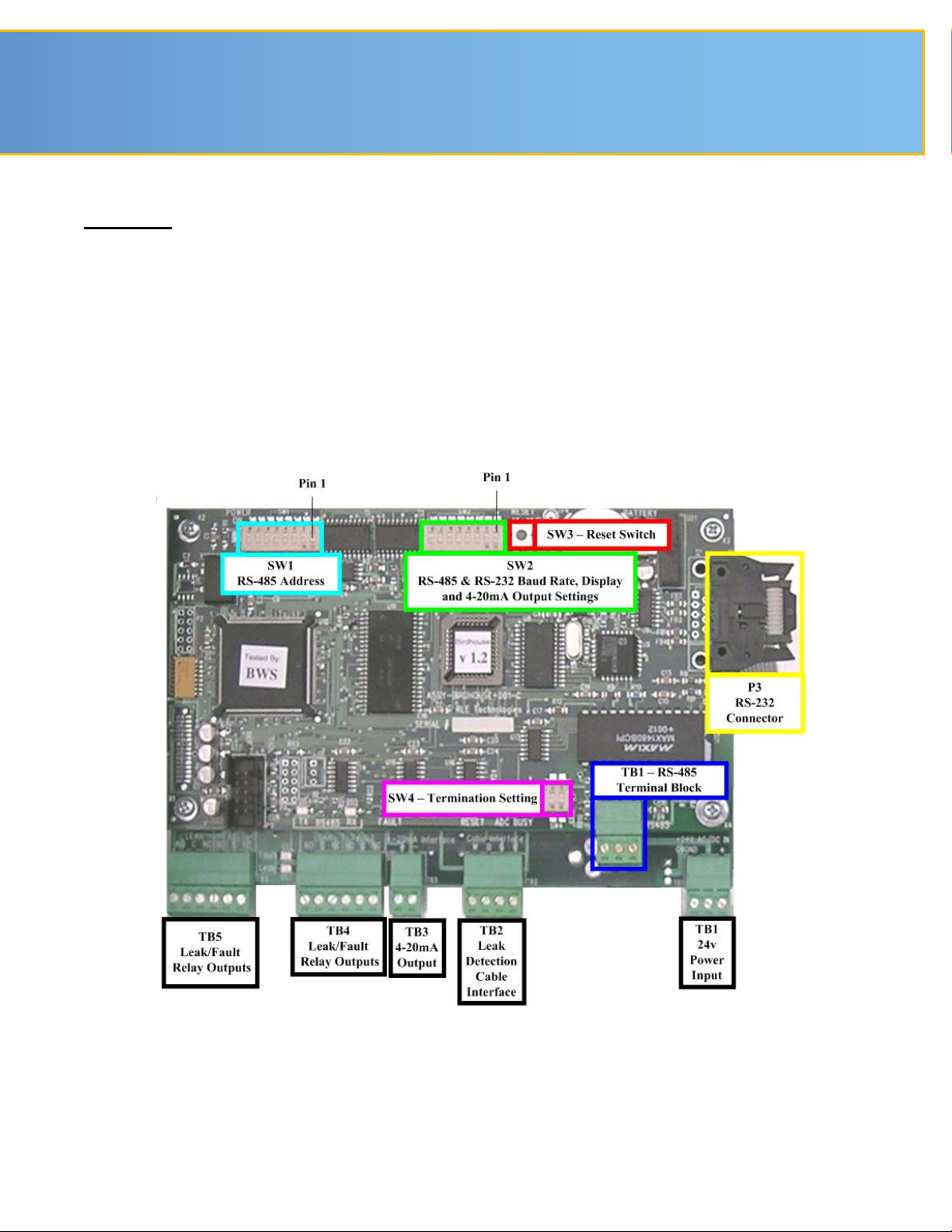
The LD5000 is comprised of three boards. All three boards are accessed when the device’s front cover is opened. The
display board is located on the inside of the door. The microprocessor board is stacked on top of the leak detection board.
Since the leak detection board is longer than the microprocessor board, the connectors on the leak detection board extend
past the end of the microprocessor board. These two boards are secured to the inside of the unit.
The connectors on the leak detection board are labeled TB1 through TB5. The connectors on the microprocessor board are
labeled TB1 and P3. The switches on the microprocessor board are labeled SW1 through SW4. Refer to the manual to set
specific settings for your requirements after the installation is complete.
Leak Detection and Microprocessor Boards
110039 Rev 0.0 (01/2007)
Page 3

SEAHAWK QUICK START GUIDE MODEL LD5000 SEAHAWK MODEL LD5000
STEP 3:
CONNECTING THE WATER LEAK DETECTION CABLE
The LD5000 is packaged with a 15’ length of leader cable. One end of this leader cable will connect to the LD5000. This end of
the cable has four exposed wires with stripped ends, white, black, green, and red. These wires will connect to the terminal block
located at TB-2, Cable Interface. From left to right, with the screws of the connector facing up, the wires should be ordered
white, black, green, and red. The other end features a mating connector which connects with the leak detection cable.
Attach (clip) the plastic EMI Suppression core to the 15’ leader cable. The plastic core should slide freely once it is placed on the
cable. Make sure the core is located close to the end of the leader cable that attaches to the LD5000 terminal block connection
(TB2).
Once the leader cable is plugged into the terminal blocks, it is ready to be connected to the leak detection cable. Attach the first
length of water leak detection cable to the leader cable. Route the water leak detection cable according to the cable layout
diagram, if provided. Refer to the manual for specific details when routing the cable around obstacles and attaching the cable to
the floor. It is important to finish the end of the leak detection cable with the end terminator. If the end terminator is not present,
a cable fault will register. See the illustration below for reference.
Toward Cable End
Toward Control Head
Leader Cable
End Terminator
Secure the cable to the floor with J-clips. J-clips are the manufacturer’s recommended installation method and can be installed as
follows:
Sense CableFemale Connector
Male Connector
Leader cable toward
control head
• Place one J-clip every three feet along the length of the water leak detection cable and one at each turn of the cable.
• If the cable is installed over an obstruction, clip the cable on both sides, as close to the obstruction as possible.
• Do not install the cable directly in front of an air conditioner. Allow a minimum of six feet between the unit and the
cable. If the cable is too close to the air conditioning unit’s air stream, the moisture from the humidifier may cause false
leak readings. If the cable must be installed in front of an air conditioning unit, place the J-clips 12 to 18 inches apart.
NOTE
It is important to finish the end of the leak detection cable with the end
terminator. If the end terminator is not present, a cable fault will
register. Note any variances between the cable layout diagram and the
actual cable installation.
:
RLE Technologies • 208 Commerce Drive, Fort Collins, CO 80524 • 970 484-6510 • 970 484-6650 Fax • www.rletech.com
Page 4

STEP 4:
CALIBRATE
The Calibrate option allows users to manually input the number of feet of cable connected to the LD5000. This
automatically calibrates the system to the cable length entered. Enter the exact cable length attached to the system to ensure
accurate calibration.
Using the front panel of the LD5000
• Select Setup and press Enter (↵).
• Select Calibrate and press Enter (↵).
• Enter cable length and press Enter (↵).
The LD5000 will automatically self calibrate and return to the main menu when complete.
STEP 5:
MAPPING THE CABLE
After the leak detection cable is laid in the desired configuration, the cable can be mapped. Mapping the cable improves the
accuracy of the LD5000 and makes it easier to locate a leak.
Mapping identifies a series of easily accessible points along the cable length. The locations of these numbered points should
be recorded on the leak detection reference map. Therefore, when the LD5000 detects a leak, the location of the leak can be
determined by comparing the distance shown on the control panel with the known positions along the cable as recorded on
the reference map.
If a reference map is not ordered from and provided by RLE Technologies, create a drawing that represents the floor plan.
This drawing must include the room layout (walls, doors, and other permanent structures), the water leak detection cable
routing path and any jumper sections of non-sensing cable.
Physically identify points along the cable routing path. Number the points and record their location on the reference map.
Using the front panel of the LD5000:
• Select System and press Enter (↵).
• Select StartMap and press Enter (↵).
• Select Accept to start mapping and press Enter (↵).
To map a point, wrap a damp paper towel or sponge around the cable at one of the previously determined points. The
LD5000 produces a short beep within approximately 30 seconds. The LCD displays the LD5000’s calculated distance to the
leak. Remove the paper towel and dry the cable. Within approximately 20 seconds, the LD5000 produces a long beep
indicating the leak has been removed, the system has returned to normal and is ready for the next point.
Go to the next point and repeat the above steps until all points along the cable are mapped and tested.
When mapping is complete, press any key on the LD5000 to exit the mapping mode. The LD5000 displays Mapping Mode
Off. Press any key again to save the map and return to the System Menu.
Select ViewMap on the LCD and record the LD5000’s reading next to each point on the reference map.
Mount the leak detection reference map alongside to the LD5000 control panel or the remote display. When a leak or cable
break occurs, refer to the map and the distance displayed on the LD5000 to determine the physical location of the leak.
110039 Rev 0.0 (01/2007)
 Loading...