

Page 1

Leak Detection
LD2100
User Guide
Version 2.6
Firmware Version 4.1.22
Page 2
Copyright and Trademark Notices
© Raymond & Lae Engineering, Inc. 2011. All rights reserved. RLE® is a registered trademark and
SeaHawk™, Falcon™, and Raptor™ are trademarks of Raymond & Lae Engineering, Inc. The
products sold by Raymond & Lae Engineering, Inc. are subject to the limited warranty, limited liability,
and other terms and conditions of sale set forth at http://rletech.com/RLE-Terms-and-Conditions.html.
Revision History
Rev. No. Date
1.0 March 2011
2.0 March 2012
2.1 May 2012
2.2 June 2012
2.3 April 2013
2.4 May 2013
2.5 June 2014
2.6 August 2014
2 LD2100 User Guide 800.518.1519
Page 3

Product Registration
Product registration helps RLE Technologies inform owners of:
• Product upgrades
• Firmware enhancements
• New products and technologies
• Special offers available only to registered users
Submit registration information at rletech.com.
Any information provided to RLE Technologies through the registration form will be regarded as
confidential. RLE will not sell or distribute any of the information to third parties.
Technical Support
Personal assistance is available Monday through Friday, from 8:00 a.m. to 5:00 p.m. MST.
A request for assistance may be sent to support@rletech.com.
Otherwise, please call us directly at: 800.518.1519, and request technical support.
The following information is located on the bottom of each LD2100 unit. Please have this information
available whenever a technical support call is placed:
Product Model Number
Product Serial Number
Product Manufacture Date
rletech.com LD2100 User Guide 3
Page 4

RLE Product Warranty
Seller warrants to the Ultimate Purchaser (the purchaser who buys for use and not for resale) that all
products furnished under this order and which are manufactured by Seller will conform to final
specifications, drawings, samples and other written descriptions approved in writing by Seller, and will be
free from defects in materials and workmanship. These warranties shall remain in effect for a period of
twelve (12) months after shipment. If the Seller installs the equipment or supplies technical direction of
installation by contract, said one year shall run from the completion of installation, provided installation is not
unreasonably delayed by Ultimate Purchaser. Parts replaced or repaired in the warranty period shall carry
the unexpired portion of the original warranty. A unit placed with the purchaser on consignment and then
later purchased will be warranted for twelve (12) months from the time the Seller receives notification of the
Purchaser's intent to purchase said consigned item. The foregoing is in its entirety is subject to the provision
that in no case will the total warranty period extend beyond 18 months from date Seller ships equipment
from point of manufacture.
Products are NOT life and safety certified. In no event shall the Seller be liable for loss, damage, or expense
directly or indirectly arising from the use of the units, or from any other cause, except as expressly stated in
this warranty. Seller makes no warranties, express or implied, including any warranty as to merchantability
or fitness for a particular purpose or use. Seller is not liable for and Purchaser waives any right of action it
has or may have against Seller for any consequential or special damages arising out of any breach of
warranty, and for any damages Purchaser may claim for damage to any property or injury or death to any
person arising out of its purchase or the use, operation, or maintenance of the product. Seller will not be
liable for any labor subcontracted or performed by Purchaser for preparation of warranted item for return to
Seller's factory or for preparation work for field repair or replacement. Invoicing of Seller for labor either
performed or subcontracted by Purchaser will not be considered as a liability by the Seller.
The liability of Seller hereunder is limited to replacing or repairing at Seller's factory or on the job site at
Seller's option, any part or parts which have been returned to the Seller and which are defective or do not
conform to such specifications, drawings or other written descriptions; provided that such part or parts are
returned by the Ultimate Purchaser within ninety (90) days after such defect is discovered. The Seller shall
have the sole right to determine if the parts are to be repaired at the job site or whether they are to be
returned to the factory for repair or replacement. All items returned to Seller for repair or replacement must
be sent freight, prepaid to its factory. Purchaser must obtain Seller's Return Goods Authorization prior to
returning items. The above conditions must be met if warranty is to be valid. Seller will not be liable for any
damage done by unauthorized repair work, unauthorized replacement parts, from any misapplication of the
item, or for damage due to accident, abuse, or act of God.
This warranty shall be exclusive of any and all other warranties express or implied and may be modified only
by writing signed by any officer of the Seller. This warranty shall extend to the Ultimate Purchaser but to no
one else. Accessories supplied by Seller but manufactured by others carry any warranty the manufacturers
have made to Seller and which can be passed on to the Ultimate Purchaser.
Seller makes no warranty with respect to whether the products sold hereunder infringe any patent, U.S. or
foreign, and Purchaser represents that any specially ordered products do not infringe any patent. Purchaser
agrees to indemnify and hold Seller harmless from any liability by virtue of any patent claims where
Purchaser has ordered a product conforming to Purchaser's specifications, or conforming to Purchaser's
specific design.
Purchaser has not relied and shall not rely on any oral representation regarding the Product sold hereunder
and any oral representation shall not bind Seller and shall not be part of any warranty.
4 LD2100 User Guide 800.518.1519
Page 5

Contents
1 Product Overview . . . . . . . . . . . . . . . . . . . . . . . . . . . . . . . . . . . . . . . . . . . . . . . . . . . 11
Description . . . . . . . . . . . . . . . . . . . . . . . . . . . . . . . . . . . . . . . . . . . . . . . . . . . . . . . . . . . . . . . . . . . . . . 11
Operation . . . . . . . . . . . . . . . . . . . . . . . . . . . . . . . . . . . . . . . . . . . . . . . . . . . . . . . . . . . . . . . . . . . . . . . 12
2 Installation . . . . . . . . . . . . . . . . . . . . . . . . . . . . . . . . . . . . . . . . . . . . . . . . . . . . . . . .13
Prepare for Installation . . . . . . . . . . . . . . . . . . . . . . . . . . . . . . . . . . . . . . . . . . . . . . . . . . . . . . . . . . . . . 13
Controls and Displays . . . . . . . . . . . . . . . . . . . . . . . . . . . . . . . . . . . . . . . . . . . . . . . . . . . . . . . . . . . . . . 14
Physical Connections . . . . . . . . . . . . . . . . . . . . . . . . . . . . . . . . . . . . . . . . . . . . . . . . . . . . . . . . . . . . . . 15
Mount the LD2100. . . . . . . . . . . . . . . . . . . . . . . . . . . . . . . . . . . . . . . . . . . . . . . . . . . . . . . . . . . . . . . . . 16
Connect the SeaHawk Leak Detection Cable . . . . . . . . . . . . . . . . . . . . . . . . . . . . . . . . . . . . . . . . . . . . 17
Secure Sensing Cable to the Floor . . . . . . . . . . . . . . . . . . . . . . . . . . . . . . . . . . . . . . . . . . . . . . . 18
Apply Power to the LD2100 . . . . . . . . . . . . . . . . . . . . . . . . . . . . . . . . . . . . . . . . . . . . . . . . . . . . . . . . . 19
Configure Communication through the Ethernet Port . . . . . . . . . . . . . . . . . . . . . . . . . . . . . . . . . . . . . . 20
Access the Configuration Menu . . . . . . . . . . . . . . . . . . . . . . . . . . . . . . . . . . . . . . . . . . . . . . . . . . 20
Configure Network Communications . . . . . . . . . . . . . . . . . . . . . . . . . . . . . . . . . . . . . . . . . . . . . . 21
Configure Communications Through the EIA-232 Port. . . . . . . . . . . . . . . . . . . . . . . . . . . . . . . . . . . . . 22
Calibrate Cable Resistance. . . . . . . . . . . . . . . . . . . . . . . . . . . . . . . . . . . . . . . . . . . . . . . . . . . . . . . . . . 23
Test the System . . . . . . . . . . . . . . . . . . . . . . . . . . . . . . . . . . . . . . . . . . . . . . . . . . . . . . . . . . . . . . . . . . 25
3 Web Interface . . . . . . . . . . . . . . . . . . . . . . . . . . . . . . . . . . . . . . . . . . . . . . . . . . . . . . 27
Home Page . . . . . . . . . . . . . . . . . . . . . . . . . . . . . . . . . . . . . . . . . . . . . . . . . . . . . . . . . . . . . . . . . . . . . . 27
Identity. . . . . . . . . . . . . . . . . . . . . . . . . . . . . . . . . . . . . . . . . . . . . . . . . . . . . . . . . . . . . . . . . . . . . . . . . . 28
Configuration. . . . . . . . . . . . . . . . . . . . . . . . . . . . . . . . . . . . . . . . . . . . . . . . . . . . . . . . . . . . . . . . . . . . . 29
Leak Settings . . . . . . . . . . . . . . . . . . . . . . . . . . . . . . . . . . . . . . . . . . . . . . . . . . . . . . . . . . . . . . . . 30
Zone Settings . . . . . . . . . . . . . . . . . . . . . . . . . . . . . . . . . . . . . . . . . . . . . . . . . . . . . . . . . . . . . . . . 33
Virtual Zone Settings . . . . . . . . . . . . . . . . . . . . . . . . . . . . . . . . . . . . . . . . . . . . . . . . . . . . . . . . . . 34
Physical Zone Settings. . . . . . . . . . . . . . . . . . . . . . . . . . . . . . . . . . . . . . . . . . . . . . . . . . . . . . . . . 34
Zone Link/URL Settings . . . . . . . . . . . . . . . . . . . . . . . . . . . . . . . . . . . . . . . . . . . . . . . . . . . . . . . . 35
Network Settings . . . . . . . . . . . . . . . . . . . . . . . . . . . . . . . . . . . . . . . . . . . . . . . . . . . . . . . . . . . . . 36
Web/Map Settings . . . . . . . . . . . . . . . . . . . . . . . . . . . . . . . . . . . . . . . . . . . . . . . . . . . . . . . . . . . . 37
Working with a Reference Map . . . . . . . . . . . . . . . . . . . . . . . . . . . . . . . . . . . . . . . . . . . . . . . 38
Clock . . . . . . . . . . . . . . . . . . . . . . . . . . . . . . . . . . . . . . . . . . . . . . . . . . . . . . . . . . . . . . . . . . . . . . 43
NTP (Network Time Protocol) . . . . . . . . . . . . . . . . . . . . . . . . . . . . . . . . . . . . . . . . . . . . . . . . . . . 44
Email-SMTP/DNS . . . . . . . . . . . . . . . . . . . . . . . . . . . . . . . . . . . . . . . . . . . . . . . . . . . . . . . . . . . . 45
SNMP/Syslog . . . . . . . . . . . . . . . . . . . . . . . . . . . . . . . . . . . . . . . . . . . . . . . . . . . . . . . . . . . . . . . . 47
EIA-485 Port/Modbus/N2 . . . . . . . . . . . . . . . . . . . . . . . . . . . . . . . . . . . . . . . . . . . . . . . . . . . . . . . 49
Bacnet . . . . . . . . . . . . . . . . . . . . . . . . . . . . . . . . . . . . . . . . . . . . . . . . . . . . . . . . . . . . . . . . . . . . . 51
Alarm Management . . . . . . . . . . . . . . . . . . . . . . . . . . . . . . . . . . . . . . . . . . . . . . . . . . . . . . . . . . . 53
System/Flash Management . . . . . . . . . . . . . . . . . . . . . . . . . . . . . . . . . . . . . . . . . . . . . . . . . . . . . 54
Product Registration. . . . . . . . . . . . . . . . . . . . . . . . . . . . . . . . . . . . . . . . . . . . . . . . . . . . . . . . . . . 54
Historical Data. . . . . . . . . . . . . . . . . . . . . . . . . . . . . . . . . . . . . . . . . . . . . . . . . . . . . . . . . . . . . . . . . . . . 55
Save your Configuration . . . . . . . . . . . . . . . . . . . . . . . . . . . . . . . . . . . . . . . . . . . . . . . . . . . . . . . . . . . . 57
4 Configure the LD2100 as a Modbus Master . . . . . . . . . . . . . . . . . . . . . . . . . . . . . .61
Connecting Distance Read Panels Using the EIA-485 Port . . . . . . . . . . . . . . . . . . . . . . . . . . . . . . . . . 61
Connect Distance-Read Panels Through the Ethernet Port . . . . . . . . . . . . . . . . . . . . . . . . . . . . . . . . . 62
Configure Modbus Communications . . . . . . . . . . . . . . . . . . . . . . . . . . . . . . . . . . . . . . . . . . . . . . . . . . . 63
rletech.com LD2100 User Guide 5
Page 6

5 Modbus Communication . . . . . . . . . . . . . . . . . . . . . . . . . . . . . . . . . . . . . . . . . . . . . 67
Implementation Basics. . . . . . . . . . . . . . . . . . . . . . . . . . . . . . . . . . . . . . . . . . . . . . . . . . . . . . . . . . . . . . 67
Modes of Transmission . . . . . . . . . . . . . . . . . . . . . . . . . . . . . . . . . . . . . . . . . . . . . . . . . . . . . . . . 67
Slave Address Field . . . . . . . . . . . . . . . . . . . . . . . . . . . . . . . . . . . . . . . . . . . . . . . . . . . . . . . . 67
Function Field. . . . . . . . . . . . . . . . . . . . . . . . . . . . . . . . . . . . . . . . . . . . . . . . . . . . . . . . . . . . . 68
Data Field. . . . . . . . . . . . . . . . . . . . . . . . . . . . . . . . . . . . . . . . . . . . . . . . . . . . . . . . . . . . . . . . 68
Error Check (Checksum) Field. . . . . . . . . . . . . . . . . . . . . . . . . . . . . . . . . . . . . . . . . . . . . . . . 68
5-1.2 Exception Responses . . . . . . . . . . . . . . . . . . . . . . . . . . . . . . . . . . . . . . . . . . . . . . . . . . 68
Packet Communications for the LD2100 . . . . . . . . . . . . . . . . . . . . . . . . . . . . . . . . . . . . . . . . . . . . . . . . 69
Function 03: Read Output Registers . . . . . . . . . . . . . . . . . . . . . . . . . . . . . . . . . . . . . . . . . . . . . . 69
Function 04: Read Input Registers . . . . . . . . . . . . . . . . . . . . . . . . . . . . . . . . . . . . . . . . . . . . . . . . 70
Function 06: Preset Single Register . . . . . . . . . . . . . . . . . . . . . . . . . . . . . . . . . . . . . . . . . . . . . . . 78
Function 16: Preset Multiple Registers . . . . . . . . . . . . . . . . . . . . . . . . . . . . . . . . . . . . . . . . . . . . . 78
RTU Framing . . . . . . . . . . . . . . . . . . . . . . . . . . . . . . . . . . . . . . . . . . . . . . . . . . . . . . . . . . . . . . . . . . . . . 79
6 Preventive Maintenance. . . . . . . . . . . . . . . . . . . . . . . . . . . . . . . . . . . . . . . . . . . . . . 81
7 Troubleshooting . . . . . . . . . . . . . . . . . . . . . . . . . . . . . . . . . . . . . . . . . . . . . . . . . . . . 83
Restoring Factory Defaults . . . . . . . . . . . . . . . . . . . . . . . . . . . . . . . . . . . . . . . . . . . . . . . . . . . . . . . . . . 85
A Update Firmware . . . . . . . . . . . . . . . . . . . . . . . . . . . . . . . . . . . . . . . . . . . . . . . . . . . 87
Preliminary Steps. . . . . . . . . . . . . . . . . . . . . . . . . . . . . . . . . . . . . . . . . . . . . . . . . . . . . . . . . . . . . . . . . . 87
Loading Flash Firmware Using MIME . . . . . . . . . . . . . . . . . . . . . . . . . . . . . . . . . . . . . . . . . . . . . . . . . . 88
Loading Flash Firmware Using TFTP . . . . . . . . . . . . . . . . . . . . . . . . . . . . . . . . . . . . . . . . . . . . . . . . . . 90
B Technical Specifications . . . . . . . . . . . . . . . . . . . . . . . . . . . . . . . . . . . . . . . . . . . . . 91
6 LD2100 User Guide 800.518.1519
Page 7

Figures
1 Product Overview . . . . . . . . . . . . . . . . . . . . . . . . . . . . . . . . . . . . . . . . . . . . . . . . 11
Figure 1.1 LD2100 Leak Detection and Communication . . . . . . . . . . . . . . . . . . . . . . . . 11
2 Installation . . . . . . . . . . . . . . . . . . . . . . . . . . . . . . . . . . . . . . . . . . . . . . . . . . . . . 13
Figure 2.1 LD2100 Connections . . . . . . . . . . . . . . . . . . . . . . . . . . . . . . . . . . . . . . . . . . . 15
Figure 2.2 Connecting the Sensing Cable . . . . . . . . . . . . . . . . . . . . . . . . . . . . . . . . . . . 17
Figure 2.3 SeaHawk Sensing Cable. . . . . . . . . . . . . . . . . . . . . . . . . . . . . . . . . . . . . . . . 17
Figure 2.4 Secure the Cable. . . . . . . . . . . . . . . . . . . . . . . . . . . . . . . . . . . . . . . . . . . . . . 18
Figure 2.5 LD2100 Log In Prompt . . . . . . . . . . . . . . . . . . . . . . . . . . . . . . . . . . . . . . . . . 20
Figure 2.6 Configuration Menu . . . . . . . . . . . . . . . . . . . . . . . . . . . . . . . . . . . . . . . . . . . . 21
Figure 2.7 Network/IP Configuration Page . . . . . . . . . . . . . . . . . . . . . . . . . . . . . . . . . . . 21
Figure 2.8 Apply Moisture to the Cable for Testing Purposes . . . . . . . . . . . . . . . . . . . . 25
3 Web Interface . . . . . . . . . . . . . . . . . . . . . . . . . . . . . . . . . . . . . . . . . . . . . . . . . . . 27
Figure 3.1 LD2100 Web Interface Home Page. . . . . . . . . . . . . . . . . . . . . . . . . . . . . . . . 27
Figure 3.2 Identity Page . . . . . . . . . . . . . . . . . . . . . . . . . . . . . . . . . . . . . . . . . . . . . . . . . 28
Figure 3.3 Configuration Page . . . . . . . . . . . . . . . . . . . . . . . . . . . . . . . . . . . . . . . . . . . . 29
Figure 3.4 Leak Settings Configuration . . . . . . . . . . . . . . . . . . . . . . . . . . . . . . . . . . . . . 30
Figure 3.5 Zone Configuration . . . . . . . . . . . . . . . . . . . . . . . . . . . . . . . . . . . . . . . . . . . . 33
Figure 3.6 Virtual Zone Settings Configuration Page . . . . . . . . . . . . . . . . . . . . . . . . . . . 34
Figure 3.7 Zone Link/URL Settings Configuration Page. . . . . . . . . . . . . . . . . . . . . . . . . 35
Figure 3.8 Network/IP Configuration Page . . . . . . . . . . . . . . . . . . . . . . . . . . . . . . . . . . . 36
Figure 3.9 Web/Map Configuration Page . . . . . . . . . . . . . . . . . . . . . . . . . . . . . . . . . . . . 37
Figure 3.10 Load a Map . . . . . . . . . . . . . . . . . . . . . . . . . . . . . . . . . . . . . . . . . . . . . . . . . . 39
Figure 3.11 Delete an Image . . . . . . . . . . . . . . . . . . . . . . . . . . . . . . . . . . . . . . . . . . . . . . 40
Figure 3.12 Web Configuration Page—Map Alarm Coordinates (Graphical) Link . . . . . . 40
Figure 3.13 Map Coordinates—Text View . . . . . . . . . . . . . . . . . . . . . . . . . . . . . . . . . . . . 41
Figure 3.14 Map with Location of Leak Shown . . . . . . . . . . . . . . . . . . . . . . . . . . . . . . . . . 42
Figure 3.15 Map (Image) Buttons on Home Page . . . . . . . . . . . . . . . . . . . . . . . . . . . . . . 42
Figure 3.16 Clock Configuration Page . . . . . . . . . . . . . . . . . . . . . . . . . . . . . . . . . . . . . . . 43
Figure 3.17 NTP Configuration Page . . . . . . . . . . . . . . . . . . . . . . . . . . . . . . . . . . . . . . . . 44
Figure 3.18 E-mail Configuration Page. . . . . . . . . . . . . . . . . . . . . . . . . . . . . . . . . . . . . . . 45
Figure 3.19 SNMP/Syslog Configuration . . . . . . . . . . . . . . . . . . . . . . . . . . . . . . . . . . . . . 47
Figure 3.20 Modbus-Slave, Bacnet-MS/TP Slave, Modbus-Master, N2 Configuration . . 49
Figure 3.21 LCD-240 Configuration . . . . . . . . . . . . . . . . . . . . . . . . . . . . . . . . . . . . . . . . . 50
Figure 3.22 Bacnet Page . . . . . . . . . . . . . . . . . . . . . . . . . . . . . . . . . . . . . . . . . . . . . . . . . 51
Figure 3.23 Alarm Management Page . . . . . . . . . . . . . . . . . . . . . . . . . . . . . . . . . . . . . . . 53
Figure 3.24 System/Flash Management Page . . . . . . . . . . . . . . . . . . . . . . . . . . . . . . . . . 54
Figure 3.25 Historical Data . . . . . . . . . . . . . . . . . . . . . . . . . . . . . . . . . . . . . . . . . . . . . . . . 55
Figure 3.26 Alarm History Text File (.txt) . . . . . . . . . . . . . . . . . . . . . . . . . . . . . . . . . . . . . 56
Figure 3.27 Trend Log . . . . . . . . . . . . . . . . . . . . . . . . . . . . . . . . . . . . . . . . . . . . . . . . . . . 56
rletech.com LD2100 User Guide 7
Page 8

Figure 3.28 System Management Page . . . . . . . . . . . . . . . . . . . . . . . . . . . . . . . . . . . . . . 57
Figure 3.29 Image Buttons on Home Page . . . . . . . . . . . . . . . . . . . . . . . . . . . . . . . . . . . 58
Figure 3.30 Saving a Map Image . . . . . . . . . . . . . . . . . . . . . . . . . . . . . . . . . . . . . . . . . . . 58
4 Configure the LD2100 as a Modbus Master . . . . . . . . . . . . . . . . . . . . . . . . . . . 61
Figure 4.1 EIA-485 Connection Diagram . . . . . . . . . . . . . . . . . . . . . . . . . . . . . . . . . . . . 61
Figure 4.2 Ethernet Connection Diagram . . . . . . . . . . . . . . . . . . . . . . . . . . . . . . . . . . . . 62
Figure 4.3 Modbus/EIA-485 Configuration, Modbus Master. . . . . . . . . . . . . . . . . . . . . . 63
Figure 4.4 Zone Configuration Webpage . . . . . . . . . . . . . . . . . . . . . . . . . . . . . . . . . . . . 63
Figure 4.5 Modbus/Physical Zone Configuration Page . . . . . . . . . . . . . . . . . . . . . . . . . 64
Figure 4.6 LD2100 Home Page Showing Modbus Slaves . . . . . . . . . . . . . . . . . . . . . . . 65
Figure 4.7 Individual Slave Unit Page. . . . . . . . . . . . . . . . . . . . . . . . . . . . . . . . . . . . . . . 65
5 Modbus Communication . . . . . . . . . . . . . . . . . . . . . . . . . . . . . . . . . . . . . . . . . . 67
6 Preventive Maintenance . . . . . . . . . . . . . . . . . . . . . . . . . . . . . . . . . . . . . . . . . . 81
7 Troubleshooting . . . . . . . . . . . . . . . . . . . . . . . . . . . . . . . . . . . . . . . . . . . . . . . . . 83
Figure 7.1 Exit to Bootloader Button on System Management Web Page . . . . . . . . . . . 85
Figure 7.2 Bootloader Page . . . . . . . . . . . . . . . . . . . . . . . . . . . . . . . . . . . . . . . . . . . . . . 85
A Update Firmware . . . . . . . . . . . . . . . . . . . . . . . . . . . . . . . . . . . . . . . . . . . . . . . . 87
Figure A.1 System Management Page . . . . . . . . . . . . . . . . . . . . . . . . . . . . . . . . . . . . . 88
Figure A.2 Choosing a Firmware File . . . . . . . . . . . . . . . . . . . . . . . . . . . . . . . . . . . . . . . 88
Figure A.3 Firmware Load Messages . . . . . . . . . . . . . . . . . . . . . . . . . . . . . . . . . . . . . . 89
Figure A.4 Current Firmware Version As Shown in LD2100 Interface . . . . . . . . . . . . . . 89
Figure A.5 Current Firmware Version As Shown in LD2100 Interface . . . . . . . . . . . . . . 90
B Technical Specifications . . . . . . . . . . . . . . . . . . . . . . . . . . . . . . . . . . . . . . . . . . 91
8 LD2100 User Guide 800.518.1519
Page 9

Tables
1 Product Overview . . . . . . . . . . . . . . . . . . . . . . . . . . . . . . . . . . . . . . . . . . . . . . . . . . 11
2 Installation . . . . . . . . . . . . . . . . . . . . . . . . . . . . . . . . . . . . . . . . . . . . . . . . . . . . . . . . 13
Table 2.1 LD2100 Controls and Displays . . . . . . . . . . . . . . . . . . . . . . . . . . . . . . . . . . . . . 14
3 Web Interface. . . . . . . . . . . . . . . . . . . . . . . . . . . . . . . . . . . . . . . . . . . . . . . . . . . . . . 27
Table 3.1 LD2100 Home Page . . . . . . . . . . . . . . . . . . . . . . . . . . . . . . . . . . . . . . . . . . . . . 28
Table 3.2 Leak Configuration Options. . . . . . . . . . . . . . . . . . . . . . . . . . . . . . . . . . . . . . . . 30
Table 3.3 Zone Settings Configuration Options . . . . . . . . . . . . . . . . . . . . . . . . . . . . . . . . 33
Table 3.4 Virtual Zone Configuration Options . . . . . . . . . . . . . . . . . . . . . . . . . . . . . . . . . . 34
Table 3.5 Zone Link/URL Settings . . . . . . . . . . . . . . . . . . . . . . . . . . . . . . . . . . . . . . . . . . 35
Table 3.6 Network/IP Configuration Options. . . . . . . . . . . . . . . . . . . . . . . . . . . . . . . . . . . 36
Table 3.7 Web/Map Configuration Options . . . . . . . . . . . . . . . . . . . . . . . . . . . . . . . . . . . . 37
Table 3.8 Clock Configuration Options . . . . . . . . . . . . . . . . . . . . . . . . . . . . . . . . . . . . . . . 43
Table 3.9 NTP Configuration Options . . . . . . . . . . . . . . . . . . . . . . . . . . . . . . . . . . . . . . . . 44
Table 3.10 Email Configuration Settings. . . . . . . . . . . . . . . . . . . . . . . . . . . . . . . . . . . . . . . 45
Table 3.11 SNMP/Syslog Menu Options. . . . . . . . . . . . . . . . . . . . . . . . . . . . . . . . . . . . . . . 47
Table 3.12 EIA-485 Port/Modbus Options . . . . . . . . . . . . . . . . . . . . . . . . . . . . . . . . . . . . . 49
Table 3.13 Bacnet Options . . . . . . . . . . . . . . . . . . . . . . . . . . . . . . . . . . . . . . . . . . . . . . . . . 52
Table 3.14 Alarm Management Options . . . . . . . . . . . . . . . . . . . . . . . . . . . . . . . . . . . . . . . 53
Table 3.15 System/Flash Management Options . . . . . . . . . . . . . . . . . . . . . . . . . . . . . . . . . 54
Table 3.16 Alarm History Log Description. . . . . . . . . . . . . . . . . . . . . . . . . . . . . . . . . . . . . . 55
4 Configure the LD2100 as a Modbus Master . . . . . . . . . . . . . . . . . . . . . . . . . . . . . 61
5 Modbus Communication . . . . . . . . . . . . . . . . . . . . . . . . . . . . . . . . . . . . . . . . . . . . 67
Table 5.1 Exception Codes . . . . . . . . . . . . . . . . . . . . . . . . . . . . . . . . . . . . . . . . . . . . . . . . 68
Table 5.2 Read Output Register Packet Structure . . . . . . . . . . . . . . . . . . . . . . . . . . . . . . 69
Table 5.3 Output Registers . . . . . . . . . . . . . . . . . . . . . . . . . . . . . . . . . . . . . . . . . . . . . . . . 69
Table 5.4 Read Input Registers Packet Structure. . . . . . . . . . . . . . . . . . . . . . . . . . . . . . . 70
Table 5.5 Input Registers . . . . . . . . . . . . . . . . . . . . . . . . . . . . . . . . . . . . . . . . . . . . . . . . . 70
Table 5.6 Status Flags (Register 30001) . . . . . . . . . . . . . . . . . . . . . . . . . . . . . . . . . . . . . 73
Table 5.7 Status Flags (Register 30010) . . . . . . . . . . . . . . . . . . . . . . . . . . . . . . . . . . . . . 74
Table 5.8 Status Flags (Register 30011) . . . . . . . . . . . . . . . . . . . . . . . . . . . . . . . . . . . . . 75
Table 5.9 Status Flags (Even Registers 30012-30040) . . . . . . . . . . . . . . . . . . . . . . . . . . 75
Table 5.10 Status Flags (Register 30042) . . . . . . . . . . . . . . . . . . . . . . . . . . . . . . . . . . . . . 76
Table 5.11 Status Flags (Register 30075) . . . . . . . . . . . . . . . . . . . . . . . . . . . . . . . . . . . . . 77
Table 5.12 Preset Single Register Packet Structure. . . . . . . . . . . . . . . . . . . . . . . . . . . . . . 78
Table 5.13 Preset Multiple Registers Packet Structure. . . . . . . . . . . . . . . . . . . . . . . . . . . . 78
Table 5.14 Response Sample. . . . . . . . . . . . . . . . . . . . . . . . . . . . . . . . . . . . . . . . . . . . . . . 79
6 Preventive Maintenance . . . . . . . . . . . . . . . . . . . . . . . . . . . . . . . . . . . . . . . . . . . . . 81
7 Troubleshooting . . . . . . . . . . . . . . . . . . . . . . . . . . . . . . . . . . . . . . . . . . . . . . . . . . . 83
Table 7.1 Troubleshooting . . . . . . . . . . . . . . . . . . . . . . . . . . . . . . . . . . . . . . . . . . . . . . . . 83
rletech.com LD2100 User Guide 9
Page 10

A Update Firmware . . . . . . . . . . . . . . . . . . . . . . . . . . . . . . . . . . . . . . . . . . . . . . . . . . 87
B Technical Specifications . . . . . . . . . . . . . . . . . . . . . . . . . . . . . . . . . . . . . . . . . . . . 91
Table B.1 Technical Specifications . . . . . . . . . . . . . . . . . . . . . . . . . . . . . . . . . . . . . . . . . . 91
10 LD2100 User Guide 800.518.1519
Page 11
1.1. Description
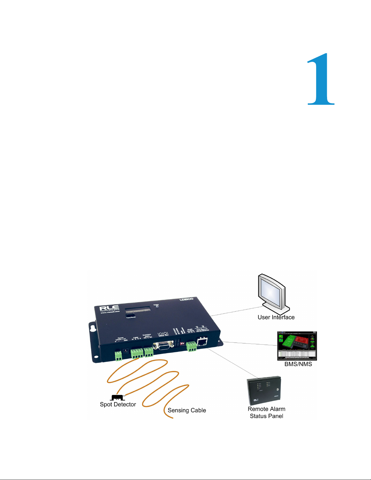
Figure 1.1
LD2100 Leak Detection and Communication
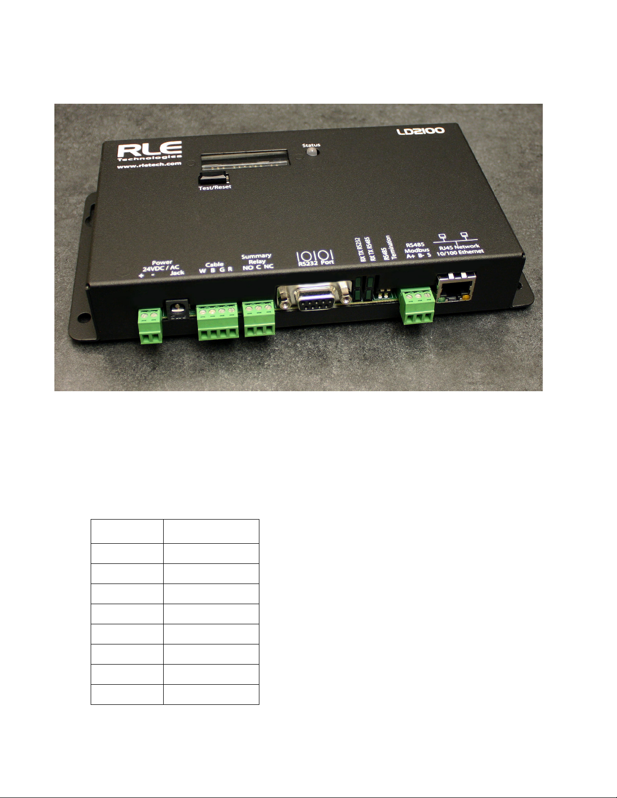
The LD2100 is a complete monitoring system that reports the presence of water and other
conductive liquids.
The LD2100 is an advanced controller that operates in conjunction with SeaHawk sensing
cable and SeaHawk spot detectors. Each LD2100 monitors up to 5,000 feet (1524m) of
sensing cable. When a conductive liquid comes in contact with the sensing cable or spot
detector, the distance to the leak is shown on the LD2100's front panel display.
C HAPTER
CHAPTER 0PRODUCT OVERVIEW
Alarm notifications are distributed via user-configurable Modbus (EIA-485 or TCP/IP),
BACnet (IP), SNMP, SMTP (email), or relay output to an alarm panel.
rletech.com LD2100 User Guide 11
Page 12

1 Product Overview
1.2. Operation
Supervised System
The LD2100 is a supervised system — it continually monitors the leak detection cable and spot
detectors for continuity. In addition to a leak triggering an alarm condition, a cable break or
excess contamination of the cable causes a cable fault indication and activates a relay. The
LD2100 sends alarm notifications to predetermined recipients when an alarm sounds. The
LD2100 produces an alarm during the following conditions:
♦ Leak detection
♦ Cable break
♦ Cable contamination
Distance-Read Leak Detection
When the LD2100's circuitry measures a current in excess of the user-defined leak threshold,
the unit's microprocessor computes the distance to the leak. The LD2100 then annunciates the
leak and logs the alarm in its event log. The summary relay has one output.
User Communication
A Web-based user interface provides information about the LD2100’s conditions. The user
interface can be used on site or remotely via network communications. The chapters and
appendices in this manual describe how to use the interface to accomplish specific
configuration and operation tasks.
The LD2100 also provides Modbus outputs via EIA-485, twisted-pair wire, or TCP/IP, as well
as BACnet/IP or BACnet/MSTP and SNMP outputs.
12 LD2100 User Guide 800.518.1519
Page 13

Installing the LD2100 involves mounting it to a wall in the appropriate location and making
the necessary connections for power, leak detection, and communications.
2.1. Prepare for Installation
Before installing the LD2100, have the following supplies available:
C HAPTER
CHAPTER 1INSTALLATION
Included with the LD2100
♦ Wall mount kit (or purchase optional enclosure, LD-ENC)
♦ Cross-over cable (blue with yellow ends)
♦ 15ft. (4.57m) leader cable
♦ End-of-line terminator (EOL)
Available from RLE, Sold Separately
♦ SeaHawk sensing cable
♦ Non-sensing cable, other accessories
♦ 24VAC power supply (part #WA-AC-24-ST) or 24VDC power supply (part
#PSWA-DC-24)
Information Required
Consult with your IT administrator to determine the following network settings for the
LD2100:
♦ IP address
♦ Subnet mask
♦ Default gateway
rletech.com LD2100 User Guide 13
Page 14
2 Installation
2.2. Controls and Displays
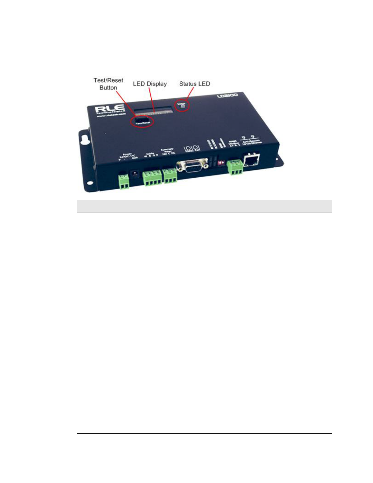
The front of the LD2100 contains the following controls and displays:
Item Description
Digital LED display
• In a normal operating state, this LED displays the
product name with a spinning bar (
|
) to the right of the name.
LD2100
• In an alarm state, the LED displays information about the
alarm condition; for example, if a leak is detected, the LED
displays a message with a leak detection cable distance
included. For example:
Leak detected
250 uA
at 675 ft (or 205.74m)
Note: Current range for a leak: 235 – 302 uA
Status LED Green: The LD2100 is powered on and in a normal operating state.
Red: The LD2100 is in an alarm state.
Test/Reset button If an alarm is sounding, briefly pressing the button turns off the
audible alarm. The Status LED remains red, and the digital LED
display continues to show the alarm condition.
In an alarm condition, whether the alarm is sounding or not,
pressing and holding this button clears the alarm.
In normal operating conditions, pressing the Reset button
causes the display to cycle through four lines:
LeakageC
nnnn uA
Length
nnn ft (or nnn m)
After a short pause, the LD2100 returns to the default display or
continues to display the alarm, depending on the value entered in
the Re-Alarm Interval field on the Leak Settings web page (see
Table 3.2, “Leak Configuration Options” on page 30 for more
information).
Table 2.1
LD2100 Controls and Displays
14 LD2100 User Guide 800.518.1519
Page 15
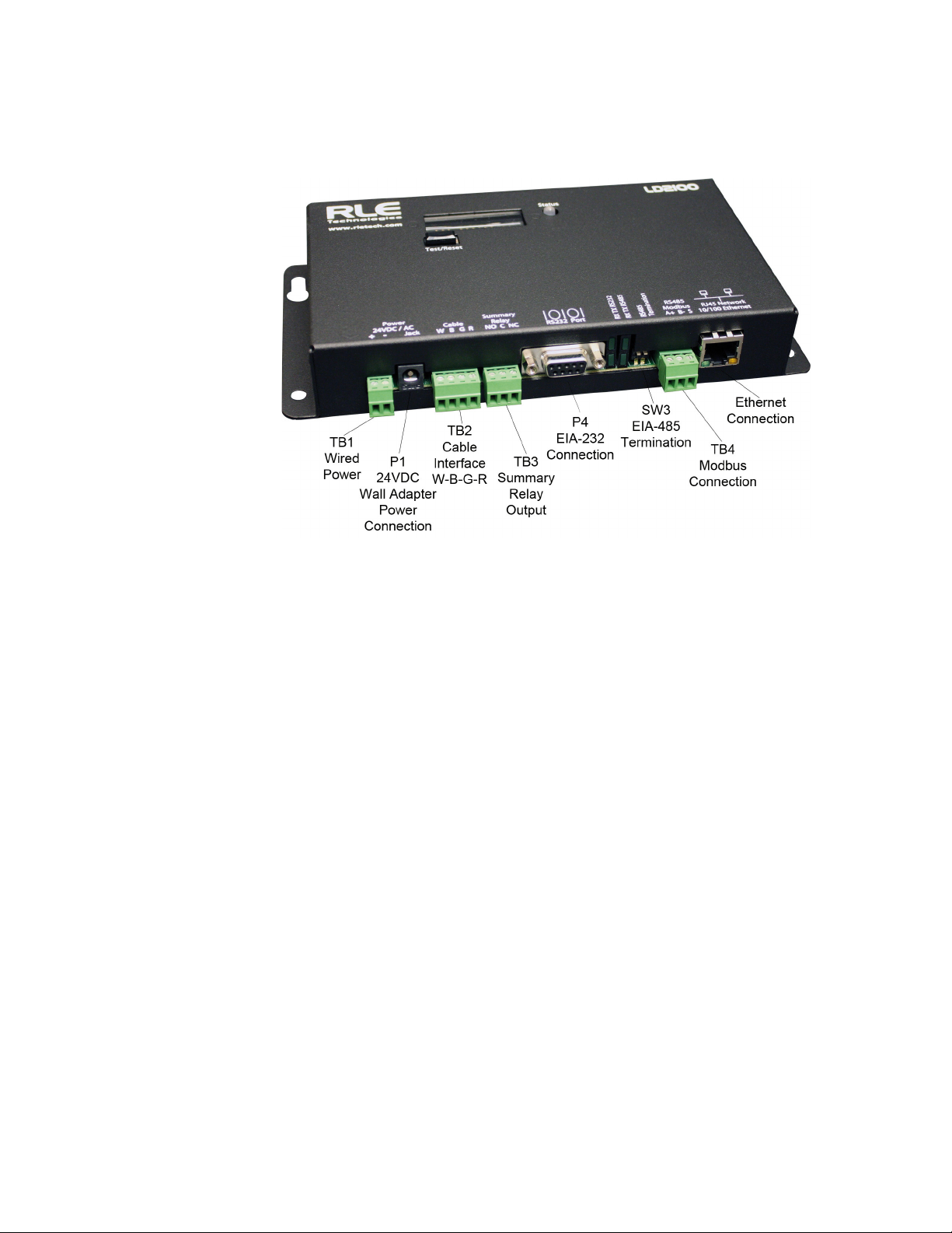
2.3. Physical Connections
The LD2100 has the following physical connections:
2 Installation
Figure 2.1
LD2100 Connections
TB1: Input Power
Power can be wired to the LD2100 through TB1. Wire the connections as follows:
TB1-1 24VDC positive (+)
TB1-2 24VDC negative (-)
P1: Input Power
RLE recommends powering the LD2100 with 24VDC wall adapter power supply. This power
supply can be purchased directly from RLE, and is offered as RLE part #PSWA-DC-24. P1 is
the connection for this power supply.
To learn more about connecting power to the LD2100, refer to Section 2.6., “Apply Power to
the LD2100” on page 19.
TB2: Cable Interface
SeaHawk sensing cable connects to TB2. Since sensing cable cannot connect directly to a leak
detection controller, the 15-foot (4.57m), non-sensing leader cable (supplied with the LD2100)
must be connected to TB2, and then the sensing cable connected to the leader cable; see
Section 2.5., “Connect the SeaHawk Leak Detection Cable” on page 17.
TB3: Summary Relay
Terminal TB3 is a Form C summary relay output. This relay provides alarm notification when
a leak, cable fault, or cable contamination is detected.
rletech.com LD2100 User Guide 15
Page 16

2 Installation
The three contacts on TB3 are labeled NO, C, and NC. Connect the alarm relay wires to TB3
as follows:
TB3-1 Leak alarm normally open (NO)
TB3-2 Leak alarm common (C)
TB3-3 Leak alarm normally closed (NC)
Both relays (all alarms) can be configured to be latched or unlatched. A latched alarm requires
a manual reset of the system once a leak or cable problem is no longer present.
P4: EIA-232 Connector
The EIA-232 uses a baud rate of 9600. The EIA-232 port is set to 8 databits, no parity, and 1
stop bit (8, N, 1). A straight through cable should be used to connect a terminal or PC to the
LD2100. This connection should only be used for setting the IP address, using advanced
diagnostics, uploading firmware, and troubleshooting. Detailed IP configuration instructions
can be found in Section 2.7., “Configure Communication through the Ethernet Port” on
page 20.
SW3: EIA-485 Termination
Switch SW3 is used when the LD2100 is the last unit on a EIA-485 network. Switch SW3 on
(push to the down position) to place a termination resistor across the + and - terminals of the
EIA-485 port.
TB4: EIA-485 Modbus Port
TB4 connects to an EIA-485 network. A grounded shield contact is provided for connection to
shielded cable. If the shield contact is used, verify the power connector is properly grounded
and there is no voltage potential between units on the network. The EIA-485 port has a
selectable baud rate (9600, 19200, or 38400) and is set to 8 databits, no parity, and 1 stop bit
(8, N, 1). Connect the EIA-485 wires to TB4 as follows:
TB3-1 A (+)
TB3-2 B (-)
TB3-3 Shield
P3: RJ45 Network
A 10/100 BaseT Ethernet connection allows the LD2100 to connect directly to a local area
network. Use a crossover cable (shipped with the LD2100; blue cable with yellow ends) for
initial connection and configuration. The default settings are as follows:
IP Address: 10.0.0.188
Subnet Mask: 255.255.255.0
2.4. Mount the LD2100
The LD2100 is a wall mounted device. Using the wall mount kit (screws and reinforcers,
included) or the LD-ENC wall-mountable enclosure (sold separately), mount the device to the
wall in a convenient location.
16 LD2100 User Guide 800.518.1519
Page 17
2 Installation
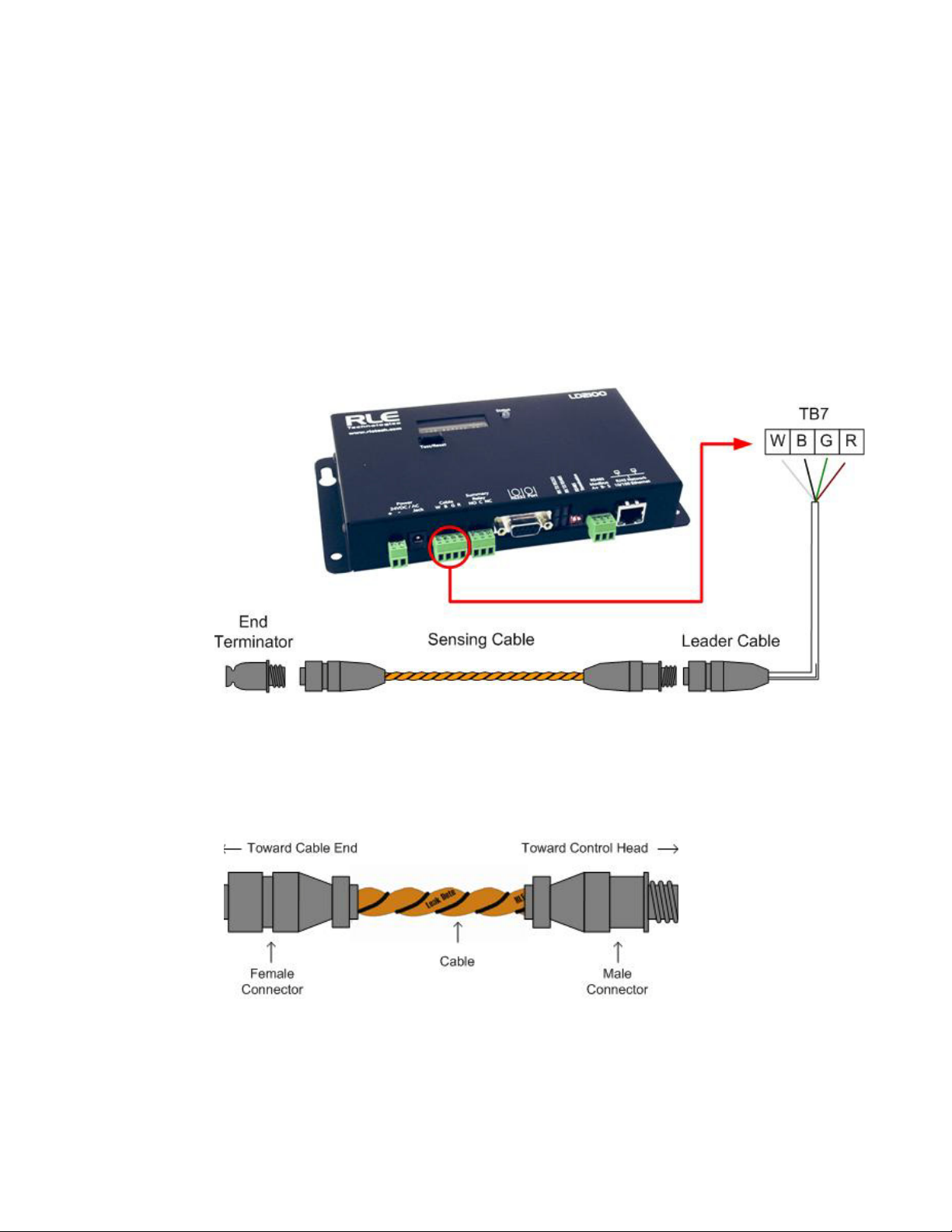
Figure 2.2
Connecting the Sensing Cable
Figure 2.3
SeaHawk Sensing Cable
2.5. Connect the SeaHawk Leak Detection Cable
The LD2100 is shipped with a 15-foot (4.57m) leader cable. Since sensing cable cannot
connect directly to a leak detection controller, one end of this leader cable connects to the
LD2100 controller, and the other end connects to the SeaHawk sensing cable. Connect each
end of the leader cable as follows:
1 With the screws of terminal block connector TB2 on the LD2100 facing up, connect the
four stripped, bare wires of the leader cable to the terminals in this order, from left to right:
white, black, green, red.
Note If the terminal connector is removed from the end of the cable, make sure the wires are in
this same order when the connector is reapplied.
2 Unscrew the end-of-line (EOL) terminator from the other end of the leader cable.
3 Attach the first length of sensing cable to the leader cable.
4 Route the sensing cable according to a cable layout diagram. Attach additional lengths of
sensing cable as needed.
5 Secure the EOL terminator to the unoccupied end of the sensing cable.
rletech.com LD2100 User Guide 17
Page 18
2 Installation
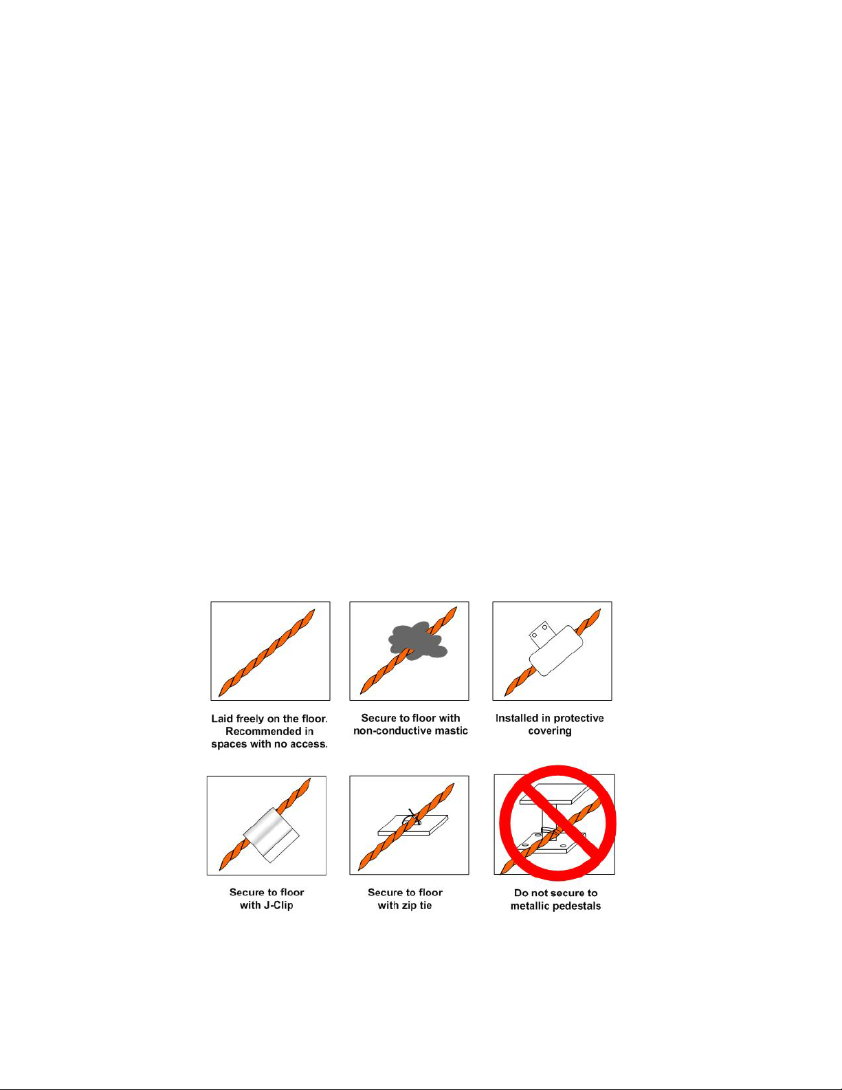
Figure 2.4
Secure the Cable
Note If the EOL terminator is not present at the end of the cable run, a cable fault will register.
If you are using a reference map, compare it with the actual cable installation. Revise any
6
discrepancies created through the physical installation of the cable.
2.5.1 Secure Sensing Cable to the Floor
Secure the sensing cable to the floor with either J-clips (RLE part #JC), or one of the other
approved methods shown in Figure 2.4. Available from RLE and designed specifically for use
with sensing cable, J-clips are the manufacturer's recommended installation method.
♦ Do not use conductive materials, such as Fire Block or caulk, on the sensing cable.
♦ To avoid contaminating the cable, clean the entire floor as much as possible. Use isopropyl
alcohol to clean the spots on the floor where the J-clips will be placed.
♦ Place one J-clip every 5 to 6 feet (1.52 to 1.83m) along the length of the sensing cable and
one at each turn of the cable. Use more J-clips if a tighter configuration is required.
♦ If the cable is installed over an obstruction, clip the cable on both sides, as close to the
obstruction as possible.
♦ The J-clip’s adhesive backing does not work well on porous concrete floors. RLE
recommends using a drop of silicone or another nonconductive adhesive to help secure the
J-clip to the floor.
IMPORTANT Do not install the cable directly in front of an air conditioner. Allow a minimum of 4 to 6 feet
(1.22 to 1.83m) between the unit and the cable. If the cable is too close to the air conditioning
unit’s air stream, the moisture from the humidifier may cause false leak readings. If the cable
must be installed in front of an air conditioning unit, place the J-clips 36 inches (0.91m) apart.
18 LD2100 User Guide 800.518.1519
Page 19

2.6. Apply Power to the LD2100
WARNING
An isolated power supply must be provided for the LD2100. In addition, a
dedicated circuit breaker must be provided within close proximity to the LD2100
and be clearly marked as the disconnecting device for the LD2100 leak detection
controller.
Do not connect 120/230 VAC to the unit, or damage will occur to the circuitry.
1 The LD2100 operates on either 24VAC or 24VDC power. Run a power supply to the
location of the unit.
2 Connect power to either the TB1 or P1 connector on the side of the LD2100.
3 Before applying power to the unit, ensure that all connections are correct and all screw
terminals are secure.
2 Installation
Note RLE recommends the use of a 24VDC wall adapter power supply (part # PSWA-DC-24),
which is available separately.
The LD2100 begins booting when power is applied. The normal operating condition of the
LD2100
LD2100 is for the Status LED to glow green and for the LED display to show
|
spinning bar (
4 Wait approximately one minute for the LD2100 to start up. No alarm should be present. If
) to the right of the product name.
with a
an alarm is present, consult Appendix 7 for troubleshooting information.
5 Go to the LD2100’s user interface to verify the length of the installed leak detection cable.
See Section 2.7., “Configure Communication through the Ethernet Port” on page 20 to set
up network access to the LD2100. See Chapter 3 for instructions for verifying the length of
the installed cable.
rletech.com LD2100 User Guide 19
Page 20
2 Installation
2.7. Configure Communication through the Ethernet
Port
IMPORTANT Consult your IT administrator before performing these steps. If you intend to change the IP
Address or Subnet Mask, obtain appropriate addresses from your IT department.
LD2100 default IP address: 10.0.0.188
LD2100 default subnet mask: 255.255.255.0
2.7.1 Access the Configuration Menu
RLE recommends using the web-based Configuration Menu to configure communications for
the LD2100. If you’d like to use the EIA-232 interface to access the LD2100, refer to
Section 2.8., “Configure Communications Through the EIA-232 Port” on page 22.
1 Plug the crossover cable (included with the LD2100) into the computer that will be used to
configure the LD2100.
Note This cable is not intended to be connected to a network hub, and will not work if it is
connected to a hub.
2
Connect the other end of the crossover cable to the Ethernet port on the back of the
LD2100.
Note Alternatively, you could use the LD2100’s EIA-232 interface to access the LD2100. See
"Configure Communications Through the EIA-232 Port" on page 22.
3
Write down the computer’s current IP address, subnet mask, and default gateway. Change
these items temporarily so that the computer can communicate with the LD2100.
4 Access the LD2100 through a Web browser by typing the LD2100’s default IP address
(10.0.0.188) into the location bar and pressing Enter.
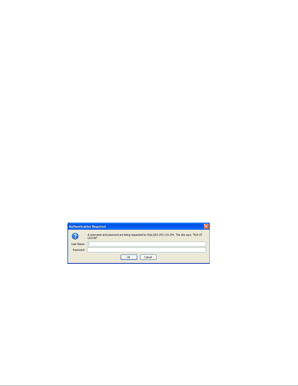
Figure 2.5
5
Enter the following:
LD2100 Log In Prompt
Default User Name: ld2100 (case sensitive)
Default Password: (No default password. Leave this field blank.)
Once you enter this information, the home page for the LD2100’s web interface displays.
20 LD2100 User Guide 800.518.1519
Page 21
2 Installation
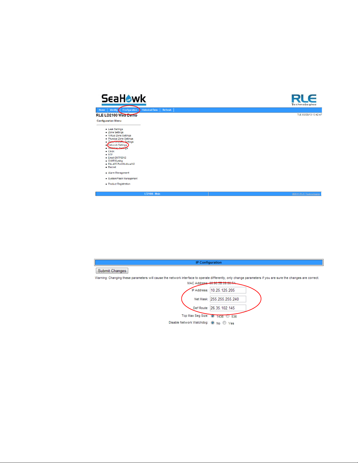
Figure 2.6
Configuration Menu
2.7.2 Configure Network Communications
To configure network communication, set the IP address for the LD2100 to the address
assigned by your IT administrator.
1 From the home page of the LD2100’s web interface, select the Configuration Menu link.
Then, select Network Settings from the Configuration Menu.
2 The Network/IP Configuration page displays. Enter the values for IP Address, Net Mask
(subnet mask), and Def Route (default gateway) provided by your IT administrator.
Once you enter the values and click the Submit Changes button, the LD2100 saves the
changes and reboots. The system status LED on front of the LD2100 stops flashing.
Figure 2.7
3
Reset the computer that’s connected to the LD2100 to its original IP address and subnet
Network/IP Configuration Page
mask. Disconnect the crossover cable.
The computer and the LD2100 are now both configured to communicate on the network.
4 To verify that the IP address on the LD2100 has been successfully changed, type the new IP
address of the LD2100 into any web browser.
5 When prompted, enter the user name and password to verify network access to the LD2100
(as you did in step 4 in the previous section).
rletech.com LD2100 User Guide 21
Page 22

2 Installation
If the login window for the LD2100 does not display:
a Verify that all cables are firmly attached.
b Verify that you entered the correct IP address for the LD2100.
c Verify that the Status light on the top of the LD2100 is green.
For further troubleshooting information, refer to Chapter 7.
2.8. Configure Communications Through the
EIA-232 Port
You can also use the EIA-232 interface to set the IP address:
1 Connect the EIA-232 port (P4) on the LD2100 to a terminal or PC running terminal
emulation software (HyperTerminal) with a 9-pin male-female straight through serial cable.
2 2. Set the appropriate communication port to 9600 baud, NO parity, 8 data bits, 1 stop
bit, (9600/N/8/1), and no software or hardware flow command.
3 Once the terminal emulation software starts, type
?
and press Enter on the keyboard and the
Main Menu should appear. If the Main Menu does not appear, check the communication
settings and make sure the unit is powered on.
4 From the Main Menu type netcfg to select the Network Configuration Menu.
♦ Enter the new IP address for the LD2100 by typing
xxx.xxx.xxx.xxx
point. For example, type
is the new IP address of the unit. Separate each field with a decimal
ip 10.0.0.50 <Enter>
ip xxx.xxx.xxx.xxx
.
, where
♦ The LD2100 erases a memory block and copies data to flash memory before rebooting.
♦ The LD2100 IP address is now set and the LD2100 can be accessed through a Web
browser using the new IP address.
5 Repeat step 4¨ to change the Subnet Mask and Def Route, if needed, using the commands
xxx.xxx.xxx.xxx
to change the Subnet Mask and
dg xxx.xxx.xxx.xxx
to change the default
gateway.
nm
22 LD2100 User Guide 800.518.1519
Page 23
2.9. Calibrate Cable Resistance
Distance-read leak detection systems are resistance-based. RLE’s orange water sensing cable
has a base resistance of 2.8 ohms/foot, while most other sensing cables, including RLE’s green
chemical resistant sensing cable, have a resistance of 4.0 ohms/foot.
The resistance of each length of sensing cable may be slightly more or less than the base
resistance due to manufacturing variances. For this reason, the cable length displayed on the
home page of the web interface may be slightly more or less than the actual length of cable
installed.
A system configured using base resistance values will still be very accurate. If you wish to fine
tune the resistance value of your LD2100 system to make it more precise, you may do so. This
will increase the accuracy of the system, and bring the LD2100’s reported installed cable
length value in line with the actual length of cable installed.
1 Ensure the LD2100 has been powered and has all the sensing cable attached to it, with no
alarms present.
2 Gather and record the following data from the home page of the web interface:
Cable Length (as reported by the LD2100)
Cable Current
Leg 1 Resistance
Leg 2 Resistance
2 Installation
Record the resistance per foot setting, as reported by the LD2100. This can be found on the
Leak Configuration page of the web interface (Configuration > Leak Settings).
Reported Resistance per Foot
3 Note the actual (physical + simulated) length of cable physically connected to the system.
For your reference:
♦ WCCS simulates 50 ft. ♦ XCON simulates 150 ft.
♦ SDZ simulates 50 ft. ♦ Nonsensing cable does not add
any length to a system
Record this sum:
Actual length of cable connected to LD2100
4 Verify the current reading on the cable from the recorded value above. This value must be
less than 15 μA in order to calibrate the system. If the current is higher than 15μA, clean the
cable. Isopropyl alcohol works well to remove any contamination that might have gotten
onto the cable during installation.
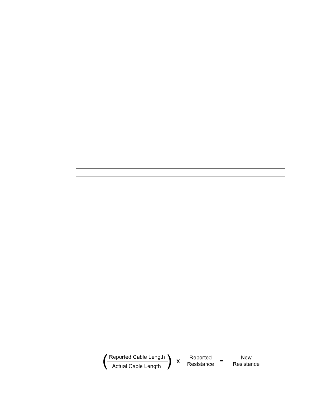
5 To calculate the most accurate resistance value for the system, divide the reported cable
length by the actual cable length, and multiply the quotient by the reported resistance.
rletech.com LD2100 User Guide 23
Page 24
2 Installation
For example:
Cable Length (as reported by the LD2100) 391 feet
Cable Current 0 μA
Leg 1 Resistance 1088 Ohms
Leg 2 Resistance 1095 Ohms
Reported Resistance 2.800 Ohms/foot
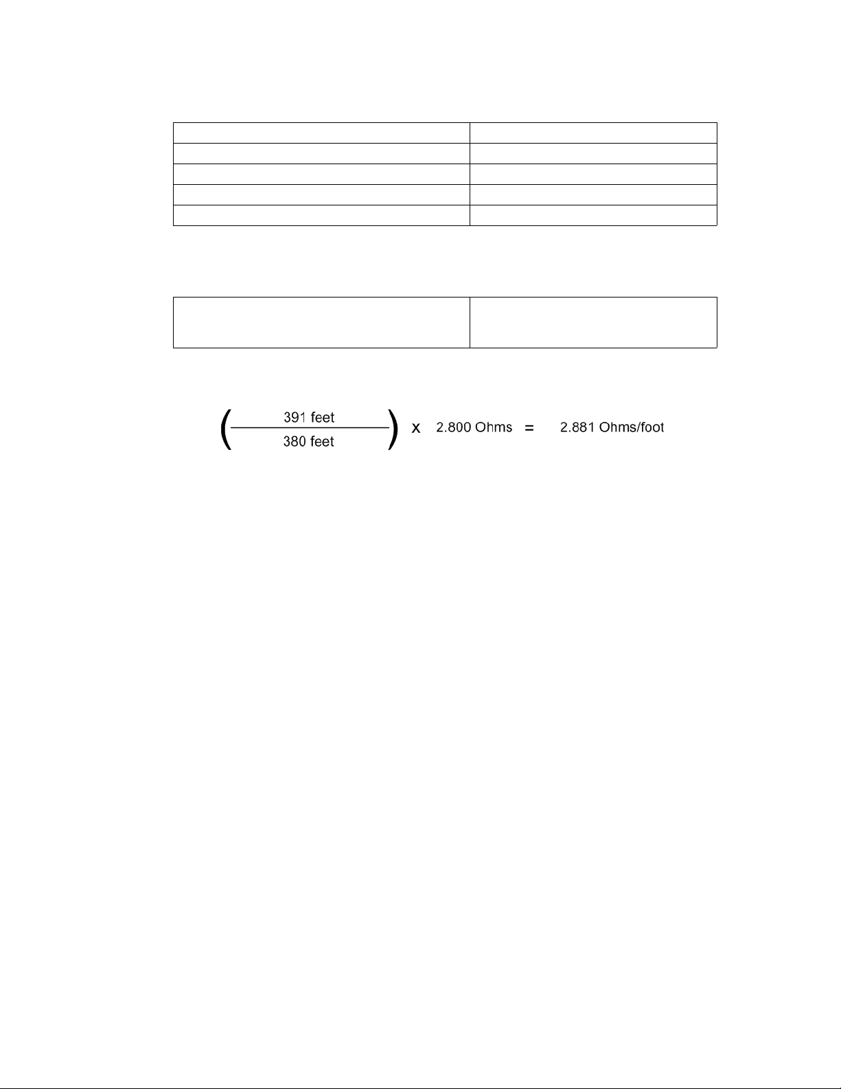
One 15 foot leader cable (leader cable does not count toward the total length of cable
installed), one weighted cable connector (simulates 50 feet of cable), and one 330 foot
section of cable are connected to the system.
Actual length of cable connected to LD2100
380 feet
0 feet + 50 feet + 330 feet
The actual resistance of the cable installed with this LD2100 is 2.881 ohms per foot.
6 Go to the Leak Configuration page (Configuration>Leak Settings) and enter the newly
calculated Resistance Per Foot value. Click Submit Changes once you have made all your
changes to this web page.
When using the web interface, remember to click the Submit Changes button to save the
adjusted resistance value.
In our example, adjusting the resistance value changed the reported cable length from 391
feet to 380 feet. This improves the accuracy of the system because the reported cable length
more closely matches the physical length of cable connected to the system.
24 LD2100 User Guide 800.518.1519
Page 25

2.10. Test the System
Now that the system is calibrated, test a few spots before mapping the system.
Note If the LD2100 is already connected to a BMS or NMS, notify monitoring personnel before you
begin testing the system.
1
To verify the LD2100’s accuracy, test three points within the length of sensing cable - one
at the beginning, one in the middle of the length, and another near the end of the length of
cable.
There are a variety of ways to simulate a leak:
2 Installation
♦ Pour a small puddle of water on the
cable while it rests on the floor.
♦ Dunk the cable in a cup of water.
♦ Soak a paper towel or rag and wrap it
loosely around the cable. This is
popular if the cable is used in pipe
applications. Be careful to wrap the
wet cloth loosely around the cable.
Do not put pressure on the cable.
IMPORTANT - To avoid inaccurate
readings, do not grip the cable with
your hand.
Figure 2.8
2 Verify that the LD2100 reports the leaks within a few feet of their actual physical location.
3 Remove the simulated leak source and return the system to its normal operating state.
Apply Moisture to the Cable for Testing Purposes
rletech.com LD2100 User Guide 25
Page 26

2 Installation
26 LD2100 User Guide 800.518.1519
Page 27
C HAPTER
CHAPTER 2WEB INTERFACE
Use the LD2100’s web interface to configure and monitor the status of the system.
To access the LD2100’s web interface, type the device’s IP address into your web browser’s
location bar. Once you navigate to the IP address, a login prompt asks for a username and
password. Enter the appropriate information, which is either the default user name (no
password), or a user name and password assigned by your system administrator.
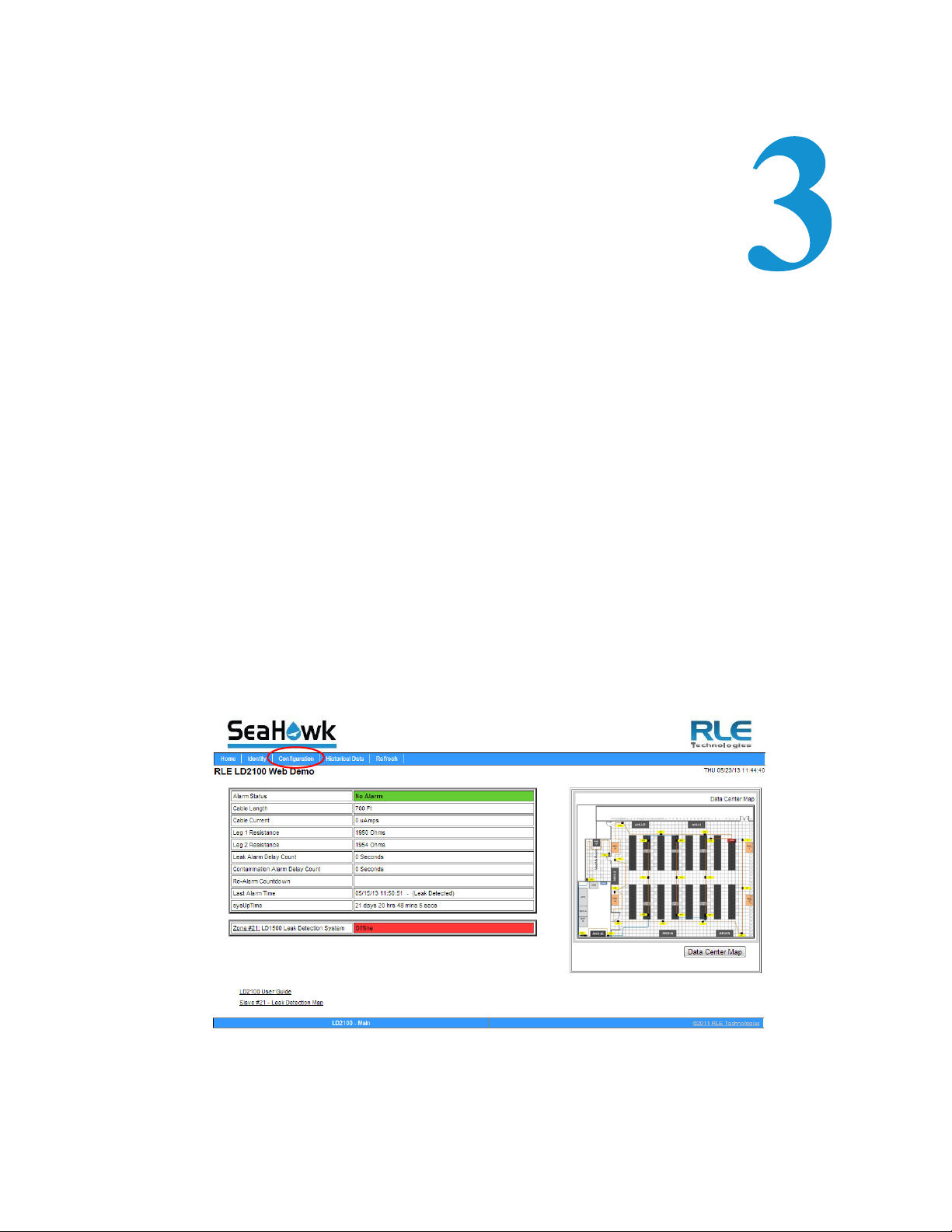
3.1. Home Page
The home page features vital system information, including current alarm status, the reported
length of sensing cable connected to the system, the last time the system went into alarm, and
the running system uptime. The image to the right of the table can be customized, and can be
linked to interactive floor maps.
Figure 3.1
rletech.com LD2100 User Guide 27
LD2100 Web Interface Home Page
Page 28
3 Web Interface
Field Description
Alarm Status If the controller is in an alarm state, details regarding the alarm are
noted in this field. The field is color coded to indicate the type of
alarm.
Cable Length The length of cable connected to the controller, as calculated by the
LD2100.
Cable Current The amount of current running on the sensing cable.
Leg 1 Resistance The resistance of Leg 1 is displayed in Ohms.
Leg 2 Resistance The resistance of Leg 2 is displayed in Ohms.
Leak Alarm Delay
Count
Contamination
Alarm Delay Count
Re-alarm
Countdown
Last Alarm Time The last time an alarm was detected
sysUp Time The amount of time that has passed since the system was last
Table 3.1
LD2100 Home Page
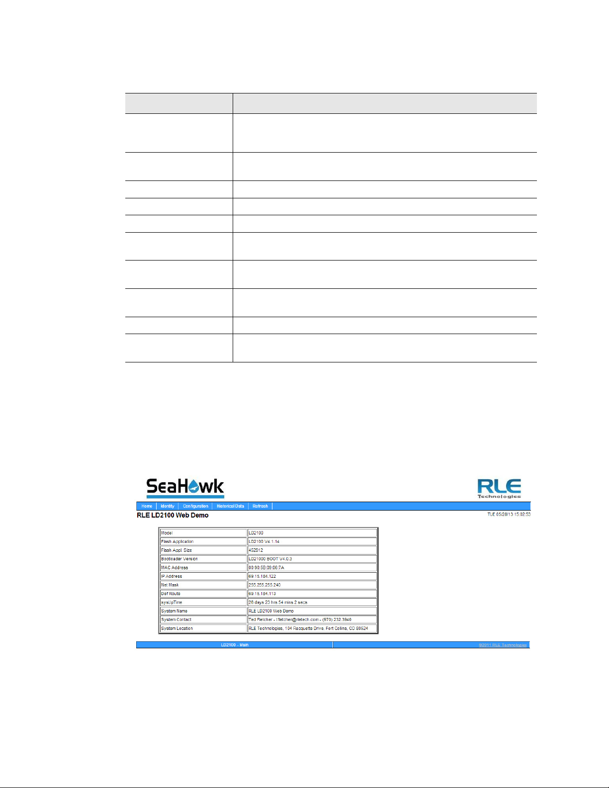
3.2 Identity
The Identity link displays basic LD2100 information, including model number, system name,
contact information, firmware version, and IP address. Most of these values can be adjusted
through the Configuration screens. This page is intended for reference only, not system
adjustment.
The amount of time (in seconds) that passes between the time a
leak is detected and when it is annunciated.
The amount of time (in seconds) that passes between the time a
contamination alarm is detected and when it is annunciated.
The amount of time remaining before an alarm is re-annunciated.
reset or powered on.
Figure 3.2
28 LD2100 User Guide 800.518.1519
Identity Page
Page 29

3.3 Configuration
The Configuration link provides access to a series of sub-menus from which users can adjust
system settings.
3 Web Interface
NOTE
Figure 3.3
Configuration Page
If any of the fields within the sub-menus are edited, be sure to click the Submit
Changes button to save the changes. If you edit the fields and navigate from the
web page without clicking the Submit Changes button, all changes will be lost.
rletech.com LD2100 User Guide 29
Page 30

3 Web Interface
3.3.1 Leak Settings
Use the Leak Configuration page to fine tune system variables, including leak and
contamination thresholds, latching and unlatching alarms, and sensing cable resistance.
Figure 3.4
Option Description
Leak Trip Point The threshold for the amount of water required to trigger a leak
Contamination Trip
Point
Leak Settings Configuration
alarm. Adjust this number to adjust the sensitivity of the leak alarm.
A lower number yields a more sensitive system, so the system will
trigger a leak alarm with less water present.
A higher number produces a less sensitive system, so more water
is required to trigger an alarm.
Enter a value between 25 and 295 microamps.
Default setting: 150uA
The threshold for the amount of contamination required to trigger a
cable contamination alarm. Adjust this number to adjust the
sensitivity of the contamination alarm.
A lower number yields a more sensitive system, so the system will
trigger a contamination alarm with less contamination present.
A higher number produces a less sensitive system, so more
contamination is required to trigger an alarm.
Enter a value between 20 and 295 microamps.
Default setting: 50uA
Table 3.2
30 LD2100 User Guide 800.518.1519
Leak Configuration Options
Page 31

3 Web Interface
Option Description
Leak Alarm Delay The amount of time that passes between the time a leak is detected
and the annunciation of the leak alarm.
The leak trip point must be exceeded for the duration of this delay.
Default setting: 20 seconds
Contamination
Alarm Delay
The amount of time that passes between the time a contamination
is detected and the annunciation of the contamination alarm.
The contamination trip point must be exceeded for the duration of
this delay.
Default setting: 40 seconds
Resistance Per Foot The resistance per foot (or meter) of cable determines the
LD2100’s ability to accurately detect the cable length installed and
calculate distances to leaks. Adjust this value to fine-tune the
accuracy of a distance-read leak detection system.
RLE’s orange water sensing cable has a base resistance of 2.800
ohms per foot. Most other sensing cables, including RLE’s green
chemical-resistant sensing cable, have a base resistance of 4.000
ohms per foot. Consult the sensing cable’s datasheet for further
information.
The resistance value must be entered as a 4-digit number between
2.000 and 4.250, with one number in the tens place and three
numbers past the decimal point (x.xxx).
Default setting: 2.800 ohms per foot
Re-Alarm Interval The LD2100 can be set to re-alarm - after a leak or contamination
has been detected, the alarm will be re-sent at a defined interval
until the alarm condition has been resolved. The re-alarm triggers
both the audible alarm and the direct notification alarm.
Enter a number from 0 to 24. A 0 in this field turns off the re-alarm
option, so only one alarm notification will be sent for each alarm.
Default setting: 0 (disabled)
Measurement
Display
Select either feet or meters to calibrate the LD2100 to the preferred
unit of measure. All distance calculations will adjust accordingly.
Default setting: Feet
Table 3.2
rletech.com LD2100 User Guide 31
Leak Configuration Options
Page 32

3 Web Interface
Option Description
Latching Alarms A non-latching alarm resets itself once a detected leak or
contamination has been resolved.
A latching alarm must be manually acknowledged before its
annunciation clears, even if the detected leak or cable problem is
no longer present.
Select Yes (latching) or No (non-latching).
Default setting: No (non-latching alarms)
Audible Alarm Select Enabled to activate the audible alarm annunciation. Disable
this option to deactivate the audible alarm annunciation.
Default setting: Disabled
Length Calibration
Factor
Table 3.2
Leak Configuration Options
Reserved for manufacturer’s use only.
Set Cable Relay Button - Used to troubleshoot the controller, this button simulates 8060
ohms of leak detection cable (approximately 2878 feet of 2.8 ohms/foot cable) for up to 5
minutes. Push the button and then look at the web interface home page. If the controller is
functioning properly, the cable length will register approximately 2878 feet, and the leg 1
and leg 2 resistance will be approximately 8060 ohms.
32 LD2100 User Guide 800.518.1519
Page 33

3 Web Interface
3.3.2 Zone Settings
You can set up the LD2100 to identify different areas where leak detection cable or spot
detectors are installed. Each area is called a zone. Up to 32 zones can be configured on the
LD2100 - the LD2100 itself is the master controller, and up to 31 slave units can connect to it.
Dividing a leak detection system into zones helps locate leaks quickly. It can also simplify
troubleshooting by allowing you to isolate different sections of cable and different rooms or
other defined areas. The LD2100 uses two different types of zones:
♦ Physical zone. A physical zone consists of a single SeaHawk distance read controller,
including the LD2100 and other RLE distance read controllers attached to it, and the
attached sensing cable. In a scenario where additional controllers are attached, the LD2100
acts as a Modbus master to other controllers. To configure physical zones, including setting
up the LD2100 as a Modbus master attaching additional controllers, follow the instructions
in Chapter 4.
♦ Virtual zone. A virtual zone is a labeled reference point in a leak detection system. A
virtual zone can consist of a room, a drip pan containing a spot detector under an air handler
unit, a combination of rooms and components, or any other defined area whose
identification would help in the location of leaks.
If you wish to establish virtual zones, go to Configuration>Zone Settings. The Zone
Configuration page displays. Select the desired zone settings.
Figure 3.5
Option Description
Zones 0 - 32 Enter an integer from 0 to 32 to indicate the number of virtual zones
Modbus Zone Traps Select the Enable radio button to enable SNMP traps for the Leak
Enable Alarm Relay
for Modbus Slaves
Table 3.3
Zone Configuration
you want to configure.
Detection Modbus master. Default: Disable.
Select the Enable radio button to activate the summary alarm when a
leak detection slave unit goes into an alarm. Default: Disable
Zone Settings Configuration Options
rletech.com LD2100 User Guide 33
Page 34

3 Web Interface
3.3.3 Virtual Zone Settings
Once you’ve designated how many virtual zones you’d like to have, you need to provide the
necessary information to define where the virtual zones are in your installation. Do this on the
Virtual Zone Settings page.
Figure 3.6
Option Description
Zone # A fixed number, 1 - 32, used to designate the Zone.
Label Type a descriptive label for the zone, 30 characters or less.
End Distance Record the sensing cable’s distance measurement at the END of
Table 3.4
Virtual Zone Settings Configuration Page
the zone.
Zone 1 starts at 0 feet / meters, and you designate the end point for
Zone 1. Zone 2 starts at zone 1’s ending distance; you designate
where Zone 2 ends. Each subsequent zone begins where the
previous zone ends.
Virtual Zone Configuration Options
3.3.4 Physical Zone Settings
Physical zones represent actual pieces of hardware that are connected to the LD2100. You’ll
use the Physical Zone Settings page to designate specific information about these physical
zones, but first you’ll need to designate the LD2100 as a Modbus Master and connect slave
devices to the LD2100. For complete physical zone configuration information, refer to
Chapter 4.
34 LD2100 User Guide 800.518.1519
Page 35

3 Web Interface
3.3.5 Zone Link/URL Settings
If you’ve connected slave devices to the LD2100, you may want access to additional
information for each of these units.
To fill this need, users can designate up to 32 links to appear on the LD2100’s home page.
Links will appear on the lower left side of the screen, below the tables of information, and
each link can connect to a specific URL. Use this page to configure all the links you’d like to
see on the home page.
Figure 3.7
Option Description
Zone A fixed number, it designates the zone associated with the link.
Link Text Users can designate links to appear on the LD2100’s home page.
URL This is the URL that the link on the home page will connect to.
Table 3.5
rletech.com LD2100 User Guide 35
Zone Link/URL Settings Configuration Page
Links will appear on the lower left side of the screen, below the
tables of information.
Additional links can be configured through the Zone Link/URL
Settings configuration link.
Enter the text for the first link here.
Enter the appropriate URL here.
Zone Link/URL Settings
Page 36

3 Web Interface
3.3.6 Network Settings
The Network/IP page displays the assigned MAC address and allows users to configure
common network information. Editing this information will change the way the web interface
operates. Only change this information if you have been in contact with your network
administrator, and are sure the changes are correct.
Figure 3.8
Option Description
MAC Address The MAC address is a unique identifier set by the manufacturer,
IP Address Set the IP address for the LD2100, so it can communicate on your
Net Mask Designate the device’s Subnet Mask. Contact your IT department
Def Route Designate the device’s default route (default gateway). If you do not
Http Port Some ISPs use alternate http ports as an added security measure.
Network/IP Configuration Page
and is non-editable.
network. If you do not have an IP address for the device, obtain one
from your IT department.
Default IP address: 10.0.0.188
for further information.
Default subnet mask: 255.255.255.0
have a default route, obtain one from your IT department.
Default device route: 10.0.0.1
Edit this field in accordance with your ISPs security settings.
Default: 0 = Port 80
Tcp Max Seg Size The LD2100 defaults to 1436 packet size for web page data. Users
may select 536 for limited bandwidth or VPN applications.
Default: 1436
Disable Network
Watchdog
Table 3.6
36 LD2100 User Guide 800.518.1519
Network/IP Configuration Options
The network watchdog is used to reboot the device if excessive
network traffic or errors are detected.
Default: No
Page 37

3 Web Interface
3.3.7 Web/Map Settings
Use this page to establish passwords and a username for the web interface, to customize the
web interface’s home page with your own graphics and links, and to create an interactive leak
detection map.
Figure 3.9
Option Description
Web Username Designate a username used to access the web interface.
Web Password Read
Only
Web Password
Read/Write
Table 3.7
Web/Map Configuration Page
Default username: ld2100
Two separate passwords can be configured on the LD2100.
The Read Only password allows users to access the LD2100’s web
interface and view the conditions of the system, but does not allow
users to make changes to the LD2100’s configuration.
Default password: field is left blank (no password required)
The second configurable password on the LD2100 provides users
with expanded access.
The Read/Write password allows users to view the conditions of the
system and make changes to the LD2100’s configuration.
Default password: field is left blank (no password required)
Web/Map Configuration Options
rletech.com LD2100 User Guide 37
Page 38

3 Web Interface
Option Description
Web Refresh Rate Decide how often the web page refreshes - checks for new data
and reloads the web page - when left in an open web browser.
Enter a value from 10 to 999 seconds. If you enter 0, the screen will
not refresh on its own - you’ll have to click the refresh button on
your web browser or press F5 to refresh the screen.
Default setting: 10 seconds
Main Page Image One image appears on the right side of the home page. Images are
uploaded through the Map page of the web interface. Select an
image from the drop down list of uploaded images.
Default setting: Seahawk
Main Page/Zone 1
Link Text
Main Page/Zone 1
Link URL
Floor Map #1 Link
Text
Floor Map #2 Link
Text
Floor Map #1
Interactive
Table 3.7
Web/Map Configuration Options
Users can designate links to appear on the LD2100’s home page.
Links will appear on the lower left side of the screen, below the
tables of information.
Additional links can be configured through the Zone Link/URL
Settings configuration link.
Enter the text for the first link here.
This is the URL that the link on the home page will connect to.
Enter the appropriate URL here.
Links to two floor maps can be displayed on the LD2100’s home
page. These links display under the image on the right side of the
screen. The maps themselves are loaded on the
Configuration>System/Flash Management Screen.
Enter the text for the link to the first map here.
Enter the text for the link to the second map here.
While the LD2100 can display two maps, only one of the maps can
be interactive. If you’d like Map #1 to be interactive, designate that
here.
3.3.7.1 Working with a Reference Map
The LD2100 allows users to upload up to 2 maps of their facilities - one of which can be
populated with interactive leak detection data. This provides users with a real-time view of
their facility, including the physical location and status of their leak detection equipment, and
a visual indication of any active alarms.
Through the mapping process, the LD2100 creates an overlay for an uploaded map image. It
superimposes the locations of your equipment - based on coordinates you designate - over the
top of your map image. This overlay is created through the links at the bottom of the Web/Map
Settings page. Once uploaded and populated, the map is accessible through the buttons
generated on the right side of the LD2100 home page.
38 LD2100 User Guide 800.518.1519
Page 39

3 Web Interface
Do not attempt to map your facility until your monitoring area is completely assembled - all of
your leak detection equipment is in place, tested, and functional.
You can draw a map yourself, or RLE can create the map from a sketch or mechanical drawing
that you provide. When creating your own map and image file, keep in mind that the image
file must be:
♦ 500kb or less in size.
♦ 4000 x 4000 pixels or less.
♦ A .png, .jpg, or .gif formatted file.
Load A Map
Before you can create the interactive overlay, you need to upload the map image file.
1 In the user interface, go to Configuration>System/Flash Management.
The System Management web page displays.
Figure 3.10
2
If you want the map to be interactive so you can set reference points for ease of leak
Load a Map
location, use the Image Index pull-down to select to upload an image to index 1.
If you want to upload a map that you will use for reference, select index 2.
Note If you upload another image to one of the two index locations where an image is already
present, the image currently in that location is overwritten.
3
Click the Choose File button to locate the file on the computer’s hard disk or on a network
drive.
4 Click the Upload button.
5 If desired, repeat these instructions to upload a second image file to the other index
location.
Return to the Web/Map Settings Configuration page. In the Floor Map #1 Link Text field, type
a title for the map. Do the same for the second image, if you have loaded one.
rletech.com LD2100 User Guide 39
Page 40

3 Web Interface
Delete an Image
If you uploaded a map or other image that you decide not to use, and you aren’t planning on
replacing it with another image, delete the image by going to Configuration>System/Flash
Management and click the button for the index location that contains the image (Image index 1
or 2).
Figure 3.11
Delete an Image
Mark Reference Points on the Map
Now that you have uploaded the map, it’s time to mark reference points on the map that you
can refer to if a leak occurs. These reference points are the overlay mentioned earlier - the
LD2100 places this data over the top of your image, to pinpoint alarms in real-time.
Since the LD2100 never actually edits your map, if you should need to update your map
image, previously designated map points will not need to be reconfigured. As long as you do
not change size of your map, previously mapped coordinates should not need to be adjusted
when you upload a new version of your map.
To mark reference points:
1 In the user interface, go to Configuration>Web/Map Settings.
The Web Configuration page displays.
Figure 3.12
40 LD2100 User Guide 800.518.1519
Web Configuration Page—Map Alarm Coordinates (Graphical) Link
Page 41

3 Web Interface
Clicking on a map’s
reference point
2 Select the Yes radio button for Floor Map #1 Interactive.
3 Click the Map Alarm Coordinates - Graphical link near the bottom of the web page.
An enlarged view of the map displays.
4 In the “Enter a distance” box at the top of the web page, type 0 to set the reference point for
the beginning of the cable.
5 Click on the map to designate the location of the 0 point of the cable. The cursor displays as
cross hairs.
When you click on the map, the distance and the x-y coordinates of the location are stored
in the LD2100’s memory.
6 Enter the next distance to be recorded and click on the map in the corresponding location.
Repeat this step for each reference point you want to add to the map.
Note It is recommended that you enter the cable distance each time the cable changes direction.
If any coordinates need to be adjusted, you can fine tune them through the Map Alarm
7
Coordinates - Text link on the Map Configuration page. Click this link to display all the
mapped coordinates and the distance readings associated with them.
Figure 3.13
rletech.com LD2100 User Guide 41
Map Coordinates—Text View
Page 42

3 Web Interface
Location of
leak displays
as red square
When a leak occurs, its location will be shown on the map.
Figure 3.14
Map with Location of Leak Shown
View an Enlargement of the Map
Maps are available from the home page and can be viewed at any time. Once you have given
the map a title, the title appears on the Home page as an active button below the map image. If
you have uploaded and titled two images, two buttons appear below the main map (the map
loaded into Image index 1). To view an enlargement of an image, click the button for the
image you want to enlarge. The enlarged image displays in a new browser window.
Figure 3.15
42 LD2100 User Guide 800.518.1519
Map (Image) Buttons on Home Page
Page 43

3 Web Interface
3.3.8 Clock
Use this link to adjust the date and time as needed. Click the Submit Changes button to save
all modifications.
Figure 3.16
Option Description
Date Adjust the current date, in mm/dd/yy format.
Time Adjust the current time in hh:mm:ss format.
Day A non-configurable field, the day of the week is generated based on
Table 3.8
Clock Configuration Page
the date.
Clock Configuration Options
rletech.com LD2100 User Guide 43
Page 44

3 Web Interface
3.3.9 NTP (Network Time Protocol)
NTP, or Network Time Protocol, is used to synchronize clocks of computer systems. NTP
synchronizes the time of a computer or device (the LD2100) with another computer or
referenced time source. NTP maintains a high level or accuracy and reliability in time stamped
events.
Figure 3.17
Option Description
NTP Server The IP address or hostname of the NTP server with which your
Update Interval Designate how often you’d like the LD2100 to access and
Select Time Zone Select the time zone in which this particular LD2100 resides.
Daylight Savings
Time
DST Begin Date Set the day DST begins at your location.
NTP Configuration Page
LD2100 will synchronize. Public NTP servers include us.pool.ntp.org
and time.nist.gov
Default setting: blank
synchronize with the NTP server. Enter a 0 to disable this feature.
Default setting: 0 (disabled)
Default setting: Western European (UTC + 0)
Enable or disable Daylight Savings Time, and designate at which
time DST goes into effect in your time zone.
Default setting: Disabled
Default setting: Second Sunday - March
DST End Date Set the day DST ends at your location.
Default setting: First Sunday - November
Table 3.9
44 LD2100 User Guide 800.518.1519
NTP Configuration Options
Page 45

3.3.10 Email-SMTP/DNS
Configure email and SMTP setting through this page.
3 Web Interface
Figure 3.18
Option Description
Access Type Select LAN to send alerts through a local network connection. Select
Options -
Email
Contamination
Alarms
Primary DNS Server Enter the IP address for the primary DNS server, as provided by your
Table 3.10
E-mail Configuration Page
None to disable the email feature.
Default setting: LAN
The LD2100 will send alerts for leak and cable break alarms. Decide
if you’d also like to receive email alerts for contamination alarms. If
so, check this box. If false alarms are often detected on your system,
you may want to disable this function
Default setting: checked (contamination alarms enabled)
internet service provider.
Default setting: 0.0.0.0
Email Configuration Settings
rletech.com LD2100 User Guide 45
Page 46

3 Web Interface
Option Description
Secondary DNS
Server
Enter the IP address for the secondary DNS server, as provided by
your internet service provider.
Default setting: 0.0.0.0
Mail (SMTP) Server Enter the URL of the mail server you will be using.
Mail Sender Address This is email sender address assigned to the LD2100.
Mail Subject Text that appears in the subject line of the email message.
Mail Recipient (1) The email address of the first recipient.
Mail Recipient (2) The email address of the second recipient.
Mail Recipient (3) The email address of the third recipient.
Mail Recipient (4) The email address of the fourth recipient.
Smtp Authentication Used for ESMTP. Use the default setting, unless otherwise directed
by your IT department.
Default setting: None
Smtp Username Used for ESMTP. Use the default setting, unless otherwise directed
by your IT department.
Default setting: Blank
Smtp Password Used for ESMTP. Use the default setting, unless otherwise directed
by your IT department.
Default setting: Blank
View Smtp Log /
View a log of all email messages that have been sent by the LD5200.
Send Test Email
This link provides access to a button that generates and sends a test
email.
Table 3.10
Email Configuration Settings
46 LD2100 User Guide 800.518.1519
Page 47

3 Web Interface
3.3.11 SNMP/Syslog
You can configure the LD2100 for SNMP communications, including setting SNMP traps.
Figure 3.19
Option Description
System Name Appears on the LD2100 Main Menu and is included as part of email
System Contact Lists the individual responsible for the LD2100. The System Contact
System Location Enter the physical location of the LD2100. The System Location is
Select SNMP Trap
Type
Table 3.11
SNMP/Syslog Configuration
notifications. Designate a name, up to 30 characters.
is only available through SNMP Gets and is not included in email or
SNMP Trap notifications. Enter up to 30 characters per line.
not included in email or SNMP Trap notifications.
Select the appropriate trap type:
V1-Trap
V2C-Trap
V2C-Inform
SNMP/Syslog Menu Options
rletech.com LD2100 User Guide 47
Page 48

3 Web Interface
Option Description
Max Inform Retries The number of times the LD2100 will attempt to resend an
undelivered trap. Enter a number 0 - 999. Enter 0 for an unlimited
number of attempts.
Default = 0 (unlimited)
Inform Interval The number of minutes that passes between inform operations.
Enter a number of minutes, 1 - 999.
Default = 1
V1/V2C Community Names
Get/Read Default setting: public
Set/Write Default setting: public
Trap Default setting: public
Trap Communities Identifies devices that receive SNMP Traps and/or Syslog messages
from the LD2100 and interact with the LD2100 over the network.
1 IP Address To add a device to the Communities list, select a community number
2 IP Address
3 IP Address
posted as “empty.” Enter the receiving device's IP Address. An IP
Address of 0.0.0.0 in this field allows any device to access the
LD2100 through an MIB browser.
4 IP Address
Send Test Trap Leak Detected
Send Test Trap Cable Break
Send Test Trap Contamination
Table 3.11
SNMP/Syslog Menu Options (continued)
Check the appropriate boxes to designate whether the device will
receive traps and/or Syslog messages.
Use these buttons to send test traps - test your system setup to
ensure all information has been entered correctly.
48 LD2100 User Guide 800.518.1519
Page 49

3 Web Interface
3.3.12 EIA-485 Port/Modbus/N2
Note If you want to configure the LD2100 as a Modbus Master, follow the instructions in Chapter 4.
If the LD2100 will communicate via the EIA-485 port, configure the necessary options here.
The screens for Modbus-Slave, Bacnet-MS/TP Slave, Modbus-Master, and N2 are the same.
The LCD-240 screen has a few additional options. To access the screen for your application,
select you choice (Modbus-Slave, Bacnet-MS/TP Slave, Modbus-Master, LCD-240, or N2)
from the drop down menu and click the Submit Changes button. The appropriate options for
your selection will display. Fill in the blanks and click the Submit Changes button again to
save your changes.
Figure 3.20
Option Description
Modbus/TCP/UDP
Slave Unit Identifier
EIA-485 Port
Function
EIA-485 Baud Rate Selectable: 9600, 19200, 38400, or 57600
EIA-485 Parity Select None, Even, or Odd
EIA-485 Slave
Address
Table 3.12
Modbus-Slave, Bacnet-MS/TP Slave, Modbus-Master, N2 Configuration
This designator is used for Modbus RTU over an Ethernet
connection.
Set the slave unit identifier, 1-254. 0 = disabled.
Select the function of the EIA-485 port: Modbus-Slave, Bacnet/MSTP Slave, Modbus-Master, LCD-240, or N2.
Click the Submit Changes button to enact the change and display
the options available for that particular port function.
Default: Modbus-Slave
Set the slave address, 1-254. 0 = disabled
EIA-485 Port/Modbus Options
rletech.com LD2100 User Guide 49
Page 50

3 Web Interface
Option Description
LCD Options A small number of companies connect an aftermarket LCD to the
LD2100. This option allows them to configure the text messages that
are pushed to that screen. Two lines of text are available on this
particular screen, containing a maximum of 40 characters each.
After selecting the LCD-240 display option, click the submit changes
button. When the page refreshes there will be eight fields to
configure.
LCD240 Identifier Enter the name of the LD2100 system.
LCD240 Normal Text The text that displays on the LCD when the system is in a normal
state.
LCD240 Alarm Text The text that displays on the LCD when the system is in an alarm
state.
LCD240 Leak Text The text that displays on the LCD when the system detects a leak.
LCD240 Cable Break
Text
LCD240
Contamination Text
LCD240 Refresh
Interval and Refresh
on Alarms Only
Checkbox
Modbus Slave
Register Display
Log/Statistics
Modbus Packet Log
N2 Register Display
Log / Statistics
Table 3.12
EIA-485 Port/Modbus Options
The text that displays on the LCD when the system has a cable
break.
The text that displays on the LCD when the system detects a
contamination alarm.
The time interval that passes between screen refreshes.
If you check the Refresh on Alarms only checkbox, the display
refreshes only when an alarm is triggered.
Click these links to display the corresponding data.
Figure 3.21
50 LD2100 User Guide 800.518.1519
LCD-240 Configuration
Page 51

3 Web Interface
3.3.13 Bacnet
The LD2100 can be configured as a BACnet slave if you would like to tie it into an existing
BMS. BACnet allows building automation and control devices to communicate, regardless of
the services they perform.
Figure 3.22
rletech.com LD2100 User Guide 51
Bacnet Page
Page 52

3 Web Interface
Option Description
BACnet Device
Designate a unique name for the LD2100, up to 30 characters
Name
BACnet Device ID Set the device ID, up to 30 characters. 0 = disabled
BACnet Description Enter a description for the device, up to 30 characters
Bacnet UDP Port Enter a 0 to specify port 47808 (0xBAC0) as the UDP port. If another
port is specified by your application, enter that value here.
Default setting: 0
Bacnet MS/TP Max
Set the slave address, 1-127. 0 = Slave only
Master
Default setting: 0
Register as Foreign
Device at IP
Registration Time-
IP address of the master device with which you’re trying to
communicate. Requires a BBMD for foreign device discovery.
Time, in seconds, for foreign device discovery.
to-Live
Foreign Device
Table #1 & #2
Fixed fields whose content is drawn from the entries in the Register
Foreign Device and Registration T-t-L fields.
Bacnet BBMD-BDT Used by some BACnet masters for discovery on different subnets.
LD5200 IP Address Non-editable, this address is configured through the Network/IP link.
(Primary) #1 IP
Designate the appropriate IP addresses.
Address
#2 IP Address
#3 IP Address
#4 IP Address
Bacnet Alarms Event Notification
Recipient #1 IP
Address
When there is a BACnet alarm, a message will be sent to this
address.
PID If necessary, enter the process identifier.
Notification Type Select unconfirmed or confirmed. If you select confirmed, the
recipient will be required to acknowledge the alarm.
Default setting: Unconfirmed
Notification Class A list of devices to be informed if an event enrollment object
determines that a warning or alarm message needs to be sent.
Priority Designate a priority to controls where conflicting control situations
may occur.
Leak Detected
Select analog or binary.
Alarms
APDU_Timeout Amount of time (milliseconds) between retransmissions of an APDU
requiring acknowledgement for which no acknowledgement has
been received.
Table 3.13
Bacnet Options
52 LD2100 User Guide 800.518.1519
Page 53

Option Description
3 Web Interface
Number_of_APDU_
Retries
Send Test Alarms Click this button to test your alarm configuration. Press the submit
Clear Test Alarms Click this button to clear the test alarms once they have been sent
Table 3.13
Bacnet Options
The maximum number of times and APDU is retransmitted.
changes button before clicking this link, or all your BACnet
configuration data will be lost.
and correctly received.
3.3.14 Alarm Management
Use this page to manage and reset current alarms, messages, and alarm history.
Figure 3.23
Option Description
Reset Leak Alarm Resets the current leak alarm and causes the LD2100 to recheck the
Clear Alarm History View the alarm history through the Historical Data link at the top of
Acknowledge
Unsent Emails
Acknowledge Snmp
Informs
Enable Power Up
Alarm Logging
Table 3.14
Alarm Management Page
current cable conditions. This clears the alarm condition if the cable
registers that the leak threshold is within an accepted range.
the web interface. Click this button to clear the alarm history of all
previous alarms.
Clears unsent emails so they aren’t sent to recipients. Events are still
logged in the historical data.
Acknowledges SNMP Informs and stops Informs from being sent out
for the current alarm condition.
Check this box and click the Submit button to log an alarm when the
LD2100 powers up. This way, if the power cycles on the unit, you will
be able to look in the alarm history log and see a record of the
activity.
Alarm Management Options
rletech.com LD2100 User Guide 53
Page 54

3 Web Interface
3.3.15 System/Flash Management
Use this page to update the LD2100’s firmware, to upload maps, and to backup the LD2100’s
configuration file. Refer to Appendix A, “Update Firmware” on page 87 for complete
firmware update instructions.
Figure 3.24
Option Description
Exit to Bootloader Access the bootloader.
Download
Configuration File
(.cfg)
Upload and Manage Image Files
Two map images can be uploaded to the LD2100. Each file must be less than 1MB, and 4000
x 4000 pixels, max.
Delete Image 1
Button
Delete Image 2
Button
Upload a New Image Two images can be uploaded to the LD2100. Use the numerical drop
Table 3.15
System/Flash Management Page
Save a copy of the LD5200’s configuration file to a local computer.
Always save a copy of the .cfg file before you update the firmware on
the LD5200.
Click this button to delete the image loaded into the LD2100 as User
Image #1.
Click this button to delete the image loaded into the LD2100 as User
Image #2.
down to designate whether you’re uploading the image as image 1 or
image 2. Click the Choose File button to navigate to a file on your
computer that you’d like to upload. Click the Upload button to
execute the upload.
System/Flash Management Options
3.3.16 Product Registration
The Product Registration link routes users to the product registration form at rletech.com.
Complete this form to receive product and firmware updates and support.
54 LD2100 User Guide 800.518.1519
Page 55

3.4. Historical Data
The Historical Data link provides access to logged historical data, including alarm and
trending data.The LD2100’s historical data includes a time-stamped chronology of events and
a trend log that contains occurrences of current leakage
3 Web Interface
Figure 3.25
Historical Data
Each entry in the alarm history is recorded in the format
following table for a description of this format.
Item Description
AH
xxx
yy
date and time
text
Table 3.16
Alarm History Log Description
Stands for “alarm history”
The log entry number for the alarm/event.
The event code, which indicates the type of event, as follows:
03 – Cable Fault
04 – Leak Detected
05 – Contamination Detected
06 – Reset/Power Up
Displayed as MM/DD/YY and HH:MM:SS (24 hour format).
Provides details about the current alarm/event.
AHxxxyy MM/DD/YY HH:MM:SS
. See the
rletech.com LD2100 User Guide 55
Page 56

3 Web Interface
Alarm history data is also available as a text file (.txt.). Click the AlarmHistory.txt or
AlarmHistroy2.txt link to download the data as a text file.
Figure 3.26
Alarm History Text File (.txt)
The Trend Log option provides a trending list of logged current leakage. This data provides
assistance in troubleshooting leaks and inaccurate readings.
Figure 3.27
Trend Log
56 LD2100 User Guide 800.518.1519
Page 57

3.5. Save your Configuration
After you have configured the LD2100, save a backup of the configuration to a safe location.
You can also use this backup to copy the configuration to other LD2100s that you are
installing at the same time. Having a copy of the configuration can save a lot of startup time.
When you save the configuration, all parameters, including x-y coordinates for a leak
detection reference map, are saved. The only item that is not saved is the map image itself. See
“Save the Map Image” on page 58 for instructions for saving the map image from the LD2100.
Back Up the Configuration
To back up the configuration:
1 In the user interface, go to Configuration>System/Flash Management.
The System Management webpage displays.
3 Web Interface
Figure 3.28
2
Click the Download Configuration File (.cfg) link at the top of the page.
System Management Page
The “Opening ld2100.cfg” pop-up for your operating system displays.
3 Select the Save File radio button and click OK.
The file is saved to your browser downloads folder, or you are prompted to select a
location. Follow these guidelines for naming the configuration file:
.cfg
♦ Always use the extension
. If you change the extension, the LD2100 will not
recognize the file if you have to upload it.
♦ The filename for the default configuration is
ld2100.cfg
. You can change
ld2100
to a
name specific to your configuration, as long as you keep the .cfg extension.
4 To upload the configuration to another LD2100, follow the same procedure used for
uploading an image file. The LD2100 distinguishes between file types by the file extension
(.cfg for configuration, or .jpg, .png, or .gif for an image file).
rletech.com LD2100 User Guide 57
Page 58

3 Web Interface
Save the Map Image
The map image is the only item that doesn’t get backed up when you save the LD2100’s
configuration. To save a copy of the map image:
1 On the Home page of the user interface, click the button for the map you want to save. This
button is underneath the map itself.
Figure 3.29
Image Buttons on Home Page
A enlarged map displays.
2 Right-click on the map image.
The Image menu for your browser displays.
Figure 3.30
3
Select Save Image As... from the menu.
Saving a Map Image
The Save Image pop-up for your operating system displays.
58 LD2100 User Guide 800.518.1519
Page 59

3 Web Interface
4 Give the image file a name. The file extension is provided for you, based on the file type of
the map you originally uploaded to the LD2100.
5 Click Save.
The map image is saved to the location and filename you specified.
rletech.com LD2100 User Guide 59
Page 60

3 Web Interface
60 LD2100 User Guide 800.518.1519
Page 61

C HAPTER
CHAPTER 3CONFIGURE THE LD2100 AS A MODBUS
MASTER
The LD2100 can act as a Modbus master to other RLE distance-read controllers. Up to 31 RLE
distance-read panels can be connected to the EIA-485 port on the LD2100. The system status
can be viewed through the LD2100 web page. The LD2100 will display leak, cable break, cable
contamination, and loss of communications alarms from the slave units connected to it.
4.1. Connecting Distance Read Panels Using the
EIA-485 Port
When using the LD2100 as a Modbus master, the slave units must be wired to the EIA-485 port
(TB4) as follows:
1 Using a two-wire configuration, connect the slave units in a 485 daisy chain.
2 Set the EIA-485 slave address for each leak detection unit:
♦ Set the first unit to address 2.
♦ Increase the address for each subsequent unit in numeric order by one (for example, the
next unit would be set to address 3)
Figure 4.1
rletech.com LD2100 User Guide 61
EIA-485 Connection Diagram
Page 62

4.2. Connect Distance-Read Panels Through the
Ethernet Port
When using the LD2100 as a Modbus master, the slave unit(s) can be connected to the
LD2100 by using the local network connection, either TCP/IP or UDP/IP, as follows:
Set the TCP/IP, UDP/IP slave address for each leak detection unit with distance-read
controllers that have an Ethernet port as follows:
1 Connect the slave units to the network using the Ethernet ports on the units.
2 Set the TCP/IP, UDP/IP slave address for each distance-read module connected over the
Ethernet by following these guidelines:
♦ Modbus communication uses port #502 for the IP address assigned.
♦ Set the first unit connected to address 2 or higher.
♦ Increase the address for each subsequent unit in numeric order by one (for example, the
next unit would be set to address 3).
Figure 4.2
62 LD2100 User Guide 800.518.1519
Ethernet Connection Diagram
Page 63

4.3. Configure Modbus Communications
Log into the LD2100 web interface and configure the unit to be a Modbus master:
1 From the Home page, click the Configuration link in the top bar. If using the EIA-485 port,
click on EIA-485 Port/Modbus/N2.
2 Once on the Modbus/EIA-485 Configuration page, select Modbus-Master or N2 from the
Select EIA-485 Port Function drop down. When completed, click on the submit changes
tab.
Figure 4.3
Modbus/EIA-485 Configuration, Modbus Master
Next, configure the slave units:
3 From the LD2100 Home page, click the Configuration link in the top bar. Choose from the
following options based on the configuration you want to set up:
a Use any of the zone addresses, 1 through 32, that are still available after virtual zones
have been configured.
b If you are not using the virtual zone feature, check the Physical-Modbus/485 option.
Trap notifications can be enabled or disabled on individual units via the Modbus/EIA485 Configuration webpage. Click the submit changes button to save changes. Return to
the Configuration webpage when finished.
Figure 4.4
Zone Configuration Webpage
rletech.com LD2100 User Guide 63
Page 64

4 For labeling Modbus/Physical zones, select Physical Zone Settings from the Configuration
Menu.
Figure 4.5
5
Once on the menu, you can configure the labels for the slave units as follows:
Modbus/Physical Zone Configuration Page
♦ If you are using the EIA-485 wiring for communication select RS-485 from the Enable
Comm Type drop down.
♦ If you are using the Ethernet port, select either Modbus TCP or Modbus UPD, depending
on the module. When using the Ethernet port, add the IP address of the module to the IP
Address field in the right column of the table.
6 Continue the previous step for each slave unit being configured from address 2 through 32.
Click on the Submit Changes tab once finished.
7 Go to the Home page of the LD2100 and verify that the system is receiving accurate
communications and proper status readings from the connected slave modules.
RLE recommends generating an alarm from each unit to confirm all communications are
working properly.
64 LD2100 User Guide 800.518.1519
Page 65

Figure 4.6
8
View the individual slave unit information by clicking on the Zone #x link.
Figure 4.7
LD2100 Home Page Showing Modbus Slaves
Individual Slave Unit Page
rletech.com LD2100 User Guide 65
Page 66

66 LD2100 User Guide 800.518.1519
Page 67

CHAPTER 4MODBUS COMMUNICATION
This chapter describes the Modbus communication protocol as supported by the LD2100
Distance Read System. The content includes details and information on how to configure the
LD2100 for communications via Modbus network
5.1. Implementation Basics
C HAPTER
The LD2100 is capable of communicating via the half-duplex EIA-485 serial communication
standard. The LD2100 is configured to act as a slave device on a common network. The EIA485 medium allows for multiple devices on a multi-drop network. The LD2100 is a slave only
device and will never initiate a communications sequence.
5.1.1 Modes of Transmission
The Modbus protocol uses ASCII and RTU modes of transmission. The LD2100 supports only
the RTU mode of transmission, with 8 data bits, no parity and one stop bit. Every Modbus
packet consists of four fields:
♦ Slave Address Field
♦ Function Field
♦ Data Field
♦ Error Check Field (Checksum)
5.1.1.1 Slave Address Field
The slave address field is one byte in length and identifies the slave device involved in the
transaction. A valid address range is between 1 and 254. The slave address is set from the
Modbus/EIA-485 Configuration web page (see “EIA-485 Port/Modbus/N2” on page 49).
rletech.com LD2100 User Guide 67
Page 68

5 Modbus Communication
5.1.1.2 Function Field
The function field is one byte in length and tells the LD2100 which function to perform. The
supported functions are 03 (Read 4xxxx output registers), 04 (Read 3xxxx input registers), 06
(Preset single register) and 16 (Preset multiple registers).
5.1.1.3 Data Field
The data field of the request is a variable length depending on the function. The data fields for
the LD2100 are 16-bit registers, transmitted high order byte first (big-endian).
5.1.1.4 Error Check (Checksum) Field
The checksum field lets the receiving device determine if the packet has transmission errors.
The LD2100 RTU mode uses a 16-bit cyclic redundancy check (CRC-16).
5.1.1.5 5-1.2 Exception Responses
If a Modbus master sends an invalid command to the LD2100 or attempts to read an invalid
register, an exception response is generated. The response packet will have the high order bit
of the function code set to one. The data field of the exception response contains the exception
error code.
Table 5.1
Code Name Description
01 Illegal Function The function code is not supported
02 Illegal Data Address Attempt to access an invalid address
03 Illegal Data Value Attempt to set a variable to an invalid value
Exception Codes
68 LD2100 User Guide 800.518.1519
Page 69

5 Modbus Communication
5.2. Packet Communications for the LD2100
This section covers the registers with the name and a brief description of each.
5.2.1 Function 03: Read Output Registers
To read the LD2100 parameter values, the master must send a Read Output Registers request
packet.
The Read Output Registers request packet specifies a start register and the number of registers
to read. The start register is numbered from zero (40001 = zero, 40002 = one, etc).
Table 5.2
Read Registers Request Packet Read Registers Response Packet
Slave Address (1 byte) Slave Address (1 byte)
03 (Function code) (1 byte) 03 (Function code) (1 byte)
Start Register (2 bytes) Byte count (1 byte)
# of registers to read (2 bytes) First register (2 bytes)
CRC Checksum (2 bytes) Second register (2 bytes)
Table 5.3
Register Name Description Units Range
40001 Leak Threshold Trip current for leak
40002 Contamination
40003 Re-Alarm Delay The time that elapses
Output Registers
Threshold
Read Output Register Packet Structure
…
Cry Checksum (2 bytes)
alarm
Trip current for
contamination alarm
between when an alarm
is detected and when it is
annunciated
25-295 uAmps 0-65535
20-295 uAmps 0-65535
0-24 Hours 0-65535
40004 Latching Alarms Designate the alarms as
latching or non-latching
40005 Silence Audible Alarm Silence the audible
alarm
40006 Reset Alarms Reset all the alarms 1=Reset 0-65535
40007 Spare 0-65535
40008 Spare 0-65535
40009 Spare 0-65535
40010 Spare 0-65535
rletech.com LD2100 User Guide 69
0=No, 1=Yes 0-65535
1=Silenced 0-65535
Page 70

5 Modbus Communication
Table 5.3
Register Name Description Units Range
40011 Spare 0-65535
40012 Spare 0-65535
40013 Spare 0-65535
40014 Spare 0-65535
40015 Spare 0-65535
40016 Leak Alarm Delay Leak Alarm Delay 5-995 seconds 0-65535
40017 Contamination Alarm
Output Registers
Delay
Contamination Alarm
Delay
5-995 seconds 0-65535
5.2.2 Function 04: Read Input Registers
To read the LD2100 input values, the master must send a Read Input Registers request packet.
The Read Input Registers request packet specifies a start register and the number of registers
to read. The start register is numbered from zero (30001 = zero, 30002 = one, etc).
Table 5.4
Read Input Registers Packet Structure
Read Registers Request Packet Read Registers Response Packet
Slave Address (1 byte) Slave Address (1 byte)
04 (Function code) (1 byte) 04 (Function code) (1 byte)
Start Register (2 bytes) Byte count (1 byte)
# of registers to read (2 bytes) First register (2 bytes)
CRC Checksum (2 bytes) Second register (2 bytes)
…
Cry Checksum (2 bytes)
Table 5.5
Register Name Description Units Range
30001 Status Bit level status None 0-65535
30002 Leak Distance Location of leak Ft/Meters 0-65535
30003 Units Unit of measure 1=Ft 0=Meters 0-65535
30004 Leak Current Leakage current on
30005 Cable Length Installed cable length Ft/Meters 0-65535
Input Registers
uAmps 0-65535
cable
30006 Loop1 Res Resistance of cable Ohms 0-65535
30007 Loop2 Res Resistance of cable Ohms 0-65535
30008 Res/Ft Resistance of cable Ohms x1000 0-65535
70 LD2100 User Guide 800.518.1519
Page 71

5 Modbus Communication
Table 5.5
Input Registers (continued)
Register Name Description Units Range
30009 Version Firmware version xx.xx X 100 0-65535
30010 Virtual Zone Alarm
Bit Level Status None 0-65535
Status
30011 Modbus Zone Enabled
Bit Level Status None 0-65535
Flags
30012 Modbus Zone2 Status Bit Level Status None 0-65535
30013 Modbus Zone2 Distance Location of leak Ft/Meters 0-65535
30014 Modbus Zone3 Status Bit Level Status None 0-65535
30015 Modbus Zone3 Distance Location of leak Ft/Meters 0-65535
30016 Modbus Zone4 Status Bit Level Status None 0-65535
30017 Modbus Zone4 Distance Location of leak Ft/Meters 0-65535
30018 Modbus Zone5 Status Bit Level Status None 0-65535
30019 Modbus Zone5 Distance Location of leak Ft/Meters 0-65535
30020 Modbus Zone6 Status Bit Level Status None 0-65535
30021 Modbus Zone6 Distance Location of leak Ft/Meters 0-65535
30022 Modbus Zone7 Status Bit Level Status None 0-65535
30023 Modbus Zone7 Distance Location of leak Ft/Meters 0-65535
30024 Modbus Zone8 Status Bit Level Status None 0-65535
30025 Modbus Zone8 Distance Location of leak Ft/Meters 0-65535
30026 Modbus Zone9 Status Bit Level Status None 0-65535
30027 Modbus Zone9 Distance Location of leak Ft/Meters 0-65535
30028 Modbus Zone10 Status Bit Level Status None 0-65535
30029 Modbus Zone10
Location of leak Ft/Meters 0-65535
Distance
30030 Modbus Zone11 Status Bit Level Status None 0-65535
30031 Modbus Zone11
Location of leak Ft/Meters 0-65535
Distance
30032 Modbus Zone12 Status Bit Level Status None 0-65535
30033 Modbus Zone12
Location of leak Ft/Meters 0-65535
Distance
30034 Modbus Zone13 Status Bit Level Status None 0-65535
30035 Modbus Zone13
Location of leak Ft/Meters 0-65535
Distance
30036 Modbus Zone14 Status Bit Level Status None 0-65535
30037 Modbus Zone14
Location of leak Ft/Meters 0-65535
Distance
30038 Modbus Zone15 Status Bit Level Status None 0-65535
30039 Modbus Zone15
Location of leak Ft/Meters 0-65535
Distance
rletech.com LD2100 User Guide 71
Page 72

5 Modbus Communication
Table 5.5
Input Registers (continued)
Register Name Description Units Range
30040 Modbus Zone16 Status Bit Level Status None 0-65535
30041 Modbus Zone16
Location of leak Ft/Meters 0-65535
Distance
Registers 30011 through 30041 are dedicated registers for Modbus Master; see Chapter 4 on page 61 for
details.
30042 Modbus Zone Enabled
Bit Level Status None 0-65535
Flags
30043 Modbus Zone17 Status Bit Level Status None 0-65535
30044 Modbus Zone17
Location of leak Ft/Meters 0-65535
Distance
30045 Modbus Zone18 Status Bit Level Status None 0-65535
30046 Modbus Zone18
Location of leak Ft/Meters 0-65535
Distance
30047 Modbus Zone19 Status Bit Level Status None 0-65535
30048 Modbus Zone19
Location of leak Ft/Meters 0-65535
Distance
30049 Modbus Zone20 Status Bit Level Status None 0-65535
30050 Modbus Zone20
Location of leak Ft/Meters 0-65535
Distance
30051 Modbus Zone21 Status Bit Level Status None 0-65535
30052 Modbus Zone21
Location of leak Ft/Meters 0-65535
Distance
30053 Modbus Zone22 Status Bit Level Status None 0-65535
30054 Modbus Zone22
Location of leak Ft/Meters 0-65535
Distance
30055 Modbus Zone23 Status Bit Level Status None 0-65535
30056 Modbus Zone23
Location of leak Ft/Meters 0-65535
Distance
30057 Modbus Zone24 Status Bit Level Status None 0-65535
30058 Modbus Zone24
Location of leak Ft/Meters 0-65535
Distance
30059 Modbus Zone25 Status Bit Level Status None 0-65535
30060 Modbus Zone25
Location of leak Ft/Meters 0-65535
Distance
30061 Modbus Zone26 Status Bit Level Status None 0-65535
30062 Modbus Zone26
Location of leak Ft/Meters 0-65535
Distance
30063 Modbus Zone27 Status Bit Level Status None 0-65535
30064 Modbus Zone27
Location of leak Ft/Meters 0-65535
Distance
30065 Modbus Zone28 Status Bit Level Status None 0-65535
72 LD2100 User Guide 800.518.1519
Page 73
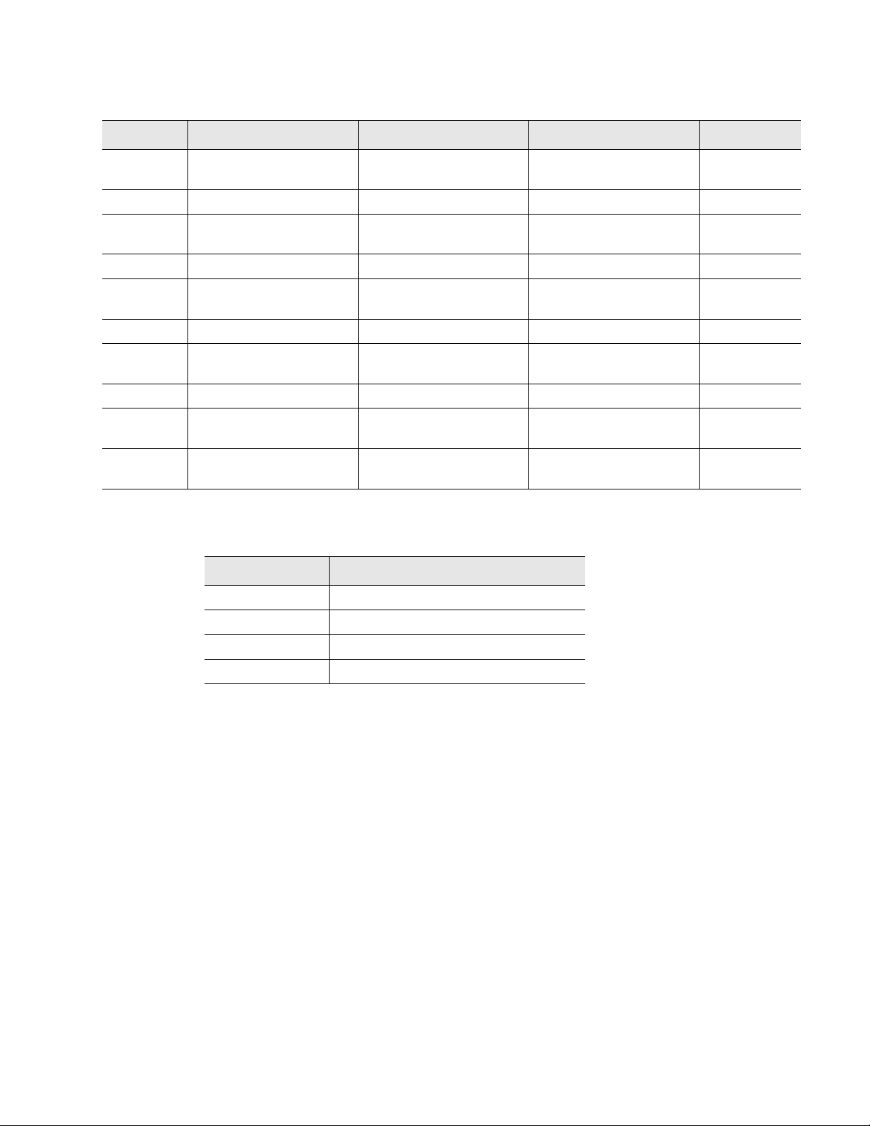
5 Modbus Communication
Table 5.5
Input Registers (continued)
Register Name Description Units Range
30066 Modbus Zone28
Location of leak Ft/Meters 0-65535
Distance
30067 Modbus Zone29 Status Bit Level Status None 0-65535
30068 Modbus Zone29
Location of leak Ft/Meters 0-65535
Distance
30069 Modbus Zone30 Status Bit Level Status None 0-65535
30070 Modbus Zone30
Location of leak Ft/Meters 0-65535
Distance
30071 Modbus Zone31 Status Bit Level Status None 0-65535
30072 Modbus Zone31
Location of leak Ft/Meters 0-65535
Distance
30073 Modbus Zone32 Status Bit Level Status None 0-65535
30074 Modbus Zone32
Location of leak Ft/Meters 0-65535
Distance
30075 Virtual Zone Alarm
Bit Level Status None 0-65535
Status
Table 5.6
Status Flags (Register 30001)
Bit Description
00 1 = Leak is Detected
01 1 = Cable Break Alarm
02 1 = Contamination is detected
04-15 Spare
rletech.com LD2100 User Guide 73
Page 74

5 Modbus Communication
Table 5.7
Status Flags (Register 30010)
Bit Description
00 1 = Zone1
01 1 = Zone2
02 1 = Zone3
03 1 = Zone4
04 1 = Zone5
05 1 = Zone6
06 1 = Zone7
07 1 = Zone8
08 1 = Zone9
09 1 = Zone10
10 1 = Zone11
11 1 = Zone12
12 1 = Zone13
13 1 = Zone14
14 1 = Zone15
15 1 = Zone16
74 LD2100 User Guide 800.518.1519
Page 75

5 Modbus Communication
Table 5.8
Status Flags (Register 30011)
Bit Description
00 1 = Not enabled
01 1 = Enabled, b1=MBZ2
02 1 = MBZ3
03 1 = MBZ4
04 1 = MBZ5
05 1 = MBZ6
06 1 = MBZ7
07 1 = MBZ8
08 1 = MBZ9
09 1 = MBZ10
10 1 = MBZ11
11 1 = MBZ12
12 1 = MBZ13
13 1 = MBZ14
14 1 = MBZ15
15 1 = MBZ16
Table 5.9
Status Flags (Even Registers 30012-30040)
Bit Description
00 1= Leak Alarm
01 1 = Cable Break
02 1 = Contamination Alarm
07 1 = Communication Loss
rletech.com LD2100 User Guide 75
Page 76

5 Modbus Communication
Table 5.10
Status Flags (Register 30042)
Bit Description
00 1 = MBZ17
01 1 = MBZ18
02 1 = MBZ19
03 1 = MBZ20
04 1 = MBZ21
05 1 = MBZ22
06 1 = MBZ23
07 1 = MBZ24
08 1 = MBZ25
09 1 = MBZ26
10 1 = MBZ27
11 1 = MBZ28
12 1 = MBZ29
13 1 = MBZ30
14 1 = MBZ31
15 1 = MBZ32
76 LD2100 User Guide 800.518.1519
Page 77

5 Modbus Communication
Table 5.11
Status Flags (Register 30075)
Bit Description
00 1 = Zone17
01 1 = Zone18
02 1 = Zone19
03 1 = Zone20
04 1 = Zone21
05 1 = Zone22
06 1 = Zone23
07 1 = Zone24
08 1 = Zone25
09 1 = Zone26
10 1 = Zone27
11 1 = Zone28
12 1 = Zone29
13 1 = Zone30
14 1 = Zone31
15 1 = Zone32
rletech.com LD2100 User Guide 77
Page 78

5 Modbus Communication
5.2.3 Function 06: Preset Single Register
To set a LD2100 parameter value, the master must send a Preset Single Register request
packet. The Preset Single Register request packet specifies a register and the data to write to
that register. The register is numbered from zero (40001 = zero, 40002 = one, etc).
Table 5.12
Preset Register Request Packet Preset Register Response Packet
Slave Address (1 byte) Slave Address (1 byte)
06 (Function code) (1 byte) 06 (Function code) (1 byte)
Register (2 bytes) Register (2 byte)
Data (2 bytes) Data (2 bytes)
Cry Checksum (2 bytes) Cry Checksum (2 bytes)
Preset Single Register Packet Structure
5.2.4 Function 16: Preset Multiple Registers
To set multiple LD2100 parameter values, the master must send a Preset Multiple Registers
request packet. The Preset Multiple Register request packet specifies a starting register, the
number of registers, a byte count and the data to write to the registers. The register is
numbered from zero (40001 = zero, 40002 = one, etc).
Table 5.13
Preset Registers Request Packet Preset Registers Response Packet
Slave Address (1 byte) Slave Address (1 byte)
Preset Multiple Registers Packet Structure
16 (Function code) (1 byte) 16 (Function code) (1 byte)
Start Register (2 bytes) Start Register (2 bytes)
# of registers to write (2 bytes) # of registers (2 bytes)
Byte Count (1 byte) CRC Checksum (2 bytes)
Data (2 bytes)
…
…
Cry Checksum (2 bytes)
78 LD2100 User Guide 800.518.1519
Page 79

5.3. RTU Framing
The example below shows a typical Query/Response from an LD2100 module.
5 Modbus Communication
Table 5.14
Slave
Address
02 04 06 00 00 00 00 00 01 B5 A3
Response Sample
Function
Code
Count Bytes
of Data
Register
Data
Msb Lsb
Register
Data
Msb Lsb
Register
Data
Msb Lsb
CRC
16
“Lsb”
Slave address 2 responds to Function Code 4 with six bytes of hexadecimal data and ends with
CRC16 checksum.
Register Values:
40001 = 0000 (hex)
40002 = 0000 (hex)
40003 = 0001 (hex)
CRC
126
“Msb”
rletech.com LD2100 User Guide 79
Page 80

5 Modbus Communication
80 LD2100 User Guide 800.518.1519
Page 81

C HAPTER
CHAPTER 5PREVENTIVE MAINTENANCE
Follow these steps monthly to test the system and ensure that the control panel is functioning
properly:
1 Place water on the cable.
2 Verify the Leak Detected alarm on the control panel.
3 Compare the distance reading on the LD2100 to a reference map (if available) to verify that
the LD2100 displays the correct leak location. See Chapter 2 on page 13 for more
information about calibrating the leak detection cable.
4 Dry the cable and verify that the LD2100 returns to normal.
5 Remove the End-of-Line terminator (EOL).
6 Verify the Cable Break alarm on the control panel.
7 Reinstall the EOL.
8 Verify that the LD2100 returns to normal.
9 Monitor the cable current monthly to verify that the cable is not being contaminated. The
LD2100 will alarm on cable contamination if the contamination is excessive.
10From the LD2100 Web interface, verify that the Cable Current is less than 25μA. If the cable
current is greater than 25μA, troubleshoot the cables to determine which cable is
contaminated. The contaminated cable should be removed, cleaned, and retested.
rletech.com LD2100 User Guide 81
Page 82

6 Preventive Maintenance
82 LD2100 User Guide 800.518.1519
Page 83

Problem Action
C HAPTER
CHAPTER 5TROUBLESHOOTING
Control Panel will not
Power Up
Cable Break Alarm
Table 7.1
Troubleshooting
1 Check with a DVOM (multi-meter) for AC or DC input power on the lower left
hand terminal block on the LD2100. If no voltage is present at terminal block,
check the circuit (breaker) or power supply the LD2100 control panel is powered
by. If voltage is present, go to step 2.
2 Contact RLE Technologies for unit replacement and/or evaluation. If voltage is
present and no LED's are illuminated, contact RLE Technologies for further
troubleshooting.
1 Verify that the leader cable from the sensing cable run is plugged into terminal
block marked “Cable.”
2 Verify that the End-of-Line terminator (EOL) is installed on the end of the orange
sensing cable run. If present at the end of the cable run, go to step 3.
3 Remove the EOL terminator from the end of the cable run and install it onto the
end of the leader cable coming from the control panel. If the condition clears,
there is a damaged/faulty section of sensing cable. Start moving the EOL
terminator to the end of each section of sensing cable to isolate the faulty
section. If the condition does not clear, go to step 4.
4 Power down (shut off) the control panel. Remove terminal block marked “Cable”
from the unit. Remove the four conductors from the leader cable wire going into
the four position terminal block. Install a jumper wire between pins 1 and 2 and
another jumper wire between pins 3 and 4. Reinstall the terminal block back into
TB2. If the cable break condition clears, there is a problem with the leader
cable. If the condition does not clear, contact RLE Technologies for further
support.
rletech.com LD2100 User Guide 83
Page 84

7 Troubleshooting
Problem Action
Control Panel not
Calculating Proper
Length of Cable
Control Panel not
Calculating Proper
Leak Distance
Cable Contamination
Alarm
1 First verify the proper wiring order into terminal block marked “Cable.” Wiring
color code should be as follows from left to right: White, Black, Green and Red.
2 Calibrate your cable. To do this, adjust the Resistance per Foot (Configuration
menu via the Web Interface). If the condition does not change, please contact
RLE Technologies. The control panel is pre-calibrated from the factory. The
overall footage should be within 5% of actual installed length.
1 Check the distance on the cable run to verify that the control panel is
monitoring. Verify there is no water along the cable run. Check to see if multiple
leaks are present on the cable. The first leak should be read and latched by the
system; however, if the system is updated or simultaneous leaks occur (2 or
more) within 30 seconds of the initial leak, the system may display the average
distance (distance of the first leak + distance of the second leak / 2). If no water
is present, go to step 2.
2 Power down (shut off) the control panel and remove the End-of-Line terminator
(EOL) from the end of the sensing cable. Locate the first section of sensing
cable from the LD2100 control panel. Where it joins to the second section of
cable, disconnect and install the EOL terminator at the end of the first section of
sensing cable. Turn power back on at control panel. Once the control panel runs
for five to ten minutes, use a damp cloth, rag or paper towel and place it on the
end of the orange sensing cable. If the leak is calculated correctly, remove the
EOL terminator; reconnect the sensing cable and move down to the next
section of cable. Repeat this process until a faulty reading is obtained. If the
reading is off at the first section of cable, there may be miscalculations from the
LD2100 unit, please contact RLE Technologies for support.
1 To clear a contamination alarm, the cable must be removed and cleaned.
Usually the cable can be cleaned by pulling it through a clean damp rag.
Table 7.1
2 If the cable is contaminated by oil, Glycol or chemicals, the cable can be
washed. Use a mild detergent solution of 1 capful to 2 gallons lukewarm water
(<105°F). Agitate the cable in a suitable container, rinse with clear lukewarm
water and wipe dry with a clean towel. The cable may also be cleaned by wiping
it down with Isopropyl Alcohol.
3 Retest the cable by connecting it to the LD2100 before reinstalling it under the
floor.
Troubleshooting (continued)
Note Contamination and/or physical damage to the cable is not covered under warranty. For all
other troubleshooting concerns and questions regarding this product, contact RLE
Technologies.
84 LD2100 User Guide 800.518.1519
Page 85

7.1. Restoring Factory Defaults
On rare occasions, you might need to set the LD2100’s configuration to the factory defaults.
For example, if you need to relocate the LD2100 to a new facility that needs a different
configuration for the LD2100, it could make sense to start with factory defaults and then adjust
the configuration as required for the new location.
To restore factory defaults to the LD2100:
1 First, save a copy of the current configuration in case you need to re-load it. See “Save your
Configuration” on page 57 for instructions.
2 In the user interface, go to Configuration>System/Flash Management.
7 Troubleshooting
Figure 7.1
3
Click the Exit to Bootloader Button.
Exit to Bootloader Button on System Management Web Page
The Bootloader web page displays.
Figure 7.2
4
Click the Restore Factory Defaults button.
Bootloader Page
The settings are restored to their defaults.
5 If you saved the .cfg file before restoring the LD2100 to its default settings, you can re-load
the .cfg file to bring back the previous configuration. Follow the same procedure used for
uploading an image file. The LD2100 distinguishes between file types by the file extension
(.cfg for configuration, or .jpg, .png, or .gif for an image file).
rletech.com LD2100 User Guide 85
Page 86

7 Troubleshooting
86 LD2100 User Guide 800.518.1519
Page 87

A PPENDIX
CHAPTER 0UPDATE FIRMWARE
Firmware updates are available on the Resources page of the RLE Web site at
www.rletech.com. Download appropriate firmware to an accessible place to load it to the
LD2100 using a LAN connection.
The instructions in this appendix describe how to load firmware using the LD2100’s MIME
(Multipurpose Internet Mail Extensions) feature. As an alternative, instructions are provided
for using TFTP (Trivial File Transfer Protocol). Use MIME if you are able; it is the more
efficient method.
A.1. Preliminary Steps
To load firmware to the LD2100 using either MIME or TFTP, first locate the correct
firmware:
1 Go to the RLE Web site Resources page at http://www.rletech.com/resources/.
2 Scroll down to the SeaHawk section and locate the firmware (a .bin file) for the LD2100.
3 Using the same filename, save the firmware to a local disk.
IMPORTANT Do not change the name of the firmware file when you save it. Otherwise, the LD2100 will not
recognize the file.
rletech.com LD2100 User Guide 87
Page 88

A Update Firmware
A.2. Loading Flash Firmware Using MIME
To use MIME to load the firmware:
On the LD2100 interface, go to Configuration>System/Flash Management.
1
Figure A.1
2
Click the Browse button.
3 Locate and choose the firmware file (.bin) that you saved from the RLE website.
System Management Page
The path and name of the firmware file (.bin) displays in the field to the left of the Browse
button.
Figure A.2
4
Click the Upload button.
88 LD2100 User Guide 800.518.1519
Choosing a Firmware File
Page 89

A Update Firmware
The firmware is loaded while the LD2100 displays a message confirming that it is loading
the new file.
Figure A.3
If the system does not reboot on its own, click the here link to display the LD2100 Home
5
Firmware Load Messages
page.
6 You can verify which firmware version is loaded by clicking the Identity link on the top bar
and looking at the value for the field called Flash Application.
Figure A.4
rletech.com LD2100 User Guide 89
Current Firmware Version As Shown in LD2100 Interface
Page 90

A Update Firmware
A.3. Loading Flash Firmware Using TFTP
Before updating the firmware, the firmware flash application must be exited and then erased.
To do this, navigate to the LD2100's System Management menu. Once here, click on the “Exit
to Bootloader” button (you must have write access to the unit in order to accomplish this task).
Once exited, you will get a bootloader webpage at the IP address of the unit. Next, click on the
“Erase Flash” button. The Flash application will be erased.
Note To erase the flash, a special username and password are required:
Username: LD2100 (all lowercase)
Password: rle2tech (all lowercase)
1
Uploading firmware via TFTP requires a TFTP Client. It may be possible to download a
free license TFTP client from the internet. Consult your IT department to determine a
compatible client program.
2 Verify that your PC and the LD2100 are on the same subnetwork (LAN).
3 Open your TFTP client. Configure the client as follows.
a Host = LD2100 IP Address
b Port = 69
c Block Size = 64, 128, 256, 512, or 1024
Note The file must be sent in binary (not ASCII).
4
Send or Put the firmware file to the LD2100. It may take ~10 seconds for the firmware
upload to begin. This will put the new firmware into effect.
5 After one minute, refresh the LD2100 webpage. Notice that the Flash field now contains the
latest firmware. Click the “Start Application” button to reboot the unit.
Figure A.5
90 LD2100 User Guide 800.518.1519
Current Firmware Version As Shown in LD2100 Interface
Page 91

A PPENDIX
CHAPTER 0TECHNICAL SPECIFICATIONS
Table B.1
Technical Specifications
Power 24VAC isolated @ 600mA max, 50/60Hz; requires power
supply (not included)
24VDC@ 600mA max; requires power supply:
PSWA-DC-24 (not included)
Inputs
Water Leak Detection Cable Compatible with SeaHawk sensing cable (not included)
Cable Input LC-KIT: 15ft (4.57m) leader cable and EOL (included)
Recommended Maximum Length 5,000ft (609m)
Detection Accuracy ± 2ft (0.6m)+/- 0.5% of the cable length
Detection Repeatability ± 2ft (0.6m) +/- 0.25% of the cable length
Detection Response Time 5-995sec, software adjustable in 5sec increments; ±2sec
Outputs
Relay 1 Form C summary relay; 1A @ 24VDC, 0.5A resistive @
120VAC; configurable for latched or non-latched
Communications Ports
Ethernet 10/100 BaseT, RJ45 connector; 500VAC RMS isolation
EIA-232 DB9 female connector; 9600 baud; No parity, 8 data bits, 1 stop
bit
EIA-485 9600, 19200, 38400, or 56700 baud (selectable); Parity: none,
even or odd, 8 data bits, 1 stop bit
Protocols
TCP/IP, HTML, TFTP IPv4.0; webpages comply with Rehabilitation Act of 1973,
sections 504 and 508, US Dept of Education (website
accessibility for computer users with disabilities)
SNMP V1: V2C MIB-2 compliant; NMS Manageable with Get, Set,
Traps
rletech.com LD2100 User Guide 91
Page 92

B Technical Specifications
Table B.1
Technical Specifications (continued)
SMTP (Email) Supports Client Authentication (plain and login); compatible
Modbus EIA-485 Slave; RTU Mode; Supports function codes 03, 04, 06 and 16;
Modbus TCP/IP Modbus Slave; TCP/IP transmission protocol; TCP/IP
BACnet/IP ASHRAE STD 135-2004 Annex J; PICS - protocol
BACnet MS/TP EIA-485
Terminal Emulation (RS-232) VT100 compatible
Alarm Notification
Audible Alarm 70dBA @ 2ft (0.6m); re-sound configurable (0-24 hrs., integer)
Visual Alarm Green, alphanumeric, 8-character dot matrix LED display; bi-
Email (Ethernet) 4 Email recipients; email sent on Alarm and Return to Normal;
SNMP Traps (Ethernet) 4 Community Strings
with ESMTP Servers
RTU mode for integration with RLE's LD5100, LD2100,
LD2000, and LD1500 products only; Johnson N2
transmission protocol for integration with RLE's LD2100,
LD2000, and LD1500 products only
implementation conformance statement
color status LED
each alarm notifies all email recipients
Logging Capabilities
Event Log Last 500 events
Trend Log Cable current level every day, for the last 288 days
Login Security
Web Browser Access (Ethernet) 1 Web password Read Only; 1 Web password Read/Write
Terminal Emulation Access None
Front Panel Interface
Display Green, alphanumeric, 8-character dot matrix LED display; bi-
color status LED
Push Buttons Test/Reset: 1
LED Indicators Power/Status: 1 bi-color (Power On: green; Alarm: red)
Operating Environment
Temperature 32° to 122°F (0° to 50°C)
Humidity 5% to 95% RH, non-condensing
Altitude 15,000ft (4,572m) max.
Storage Environment -4° to 185°F (-20° to 85°C)
Dimensions 8.0"W x 4.25"H x 1.25"D (203mmW x 108mmH x31.75mmD)
Weight 1.5 lbs. (680g)
Mounting Wall mountable; wall-mount enclosure LD-ENC or LD-ENC-NP
(optional)
Certifications CE; ETL listed: conforms to UL STD 61010-1, EN STD
61010-1; certified to CSA C22.2 STD NO. 61010-1; RoHS
compliant
92 LD2100 User Guide 800.518.1519
 Loading...