

Page 1
Leak Detection
LD2000
User Guide
Page 2

Copyright and Trademark Notices
© Raymond & Lae Engineering, Inc. 2011. All rights reserved. RLE® is a registered trademark and
Seahawk™, Falcon™, and Raptor™ are trademarks of Raymond & Lae Engineering, Inc. The
products sold by Raymond & Lae Engineering, Inc. are subject to the limited warranty, limited liability,
and other terms and conditions of sale set forth at http://rletech.com/RLE-Terms-and-Conditions.html.
Revision History
Rev. No. Date
2.0 June 2010
2.1 October 2010
3.0 December 2010
3.1 February 2011
Note: As necessary, blank pages are added to make the page count even.
rletech.com 2 970.484.6510
Page 3

Product Registration
Product registration helps RLE Technologies inform owners of:
• Product upgrades
• Firmware enhancements
• New products and technologies
• Special offers available only to registered users
Submit registration information on the Support/Product Registration webpage at www.rletech.com.
Any information provided to RLE Technologies through the registration form will be regarded as
confidential. RLE will not sell or distribute any of the information to third parties. To read our Privacy
Policy, please visit our website: www.rletech.com.
Technical Support
Personal assistance is available Monday through Friday, from 8:00 a.m. to 5:00 p.m. MST.
A request for assistance may be sent to support@rletech.com.
Otherwise, please call us directly at: (970) 484-6510, and press “2” for technical support.
The following information is located on the bottom of each LD2000 unit. Please have this information
available whenever a technical support call is placed:
Product Model Number
Product Serial Number
Product Manufacture Date
970.484.6510 3 rletech.com
Page 4

RLE Product Warranty
Seller warrants to the Ultimate Purchaser (the purchaser who buys for use and not for resale) that all
products furnished under this order and which are manufactured by Seller will conform to final
specifications, drawings, samples and other written descriptions approved in writing by Seller, and will be
free from defects in materials and workmanship. These warranties shall remain in effect for a period of
twelve (12) months after shipment. If the Seller installs the equipment or supplies technical direction of
installation by contract, said one year shall run from the completion of installation, provided installation is not
unreasonably delayed by Ultimate Purchaser. Parts replaced or repaired in the warranty period shall carry
the unexpired portion of the original warranty. A unit placed with the purchaser on consignment and then
later purchased will be warranted for twelve (12) months from the time the Seller receives notification of the
Purchaser's intent to purchase said consigned item. The foregoing is in its entirety is subject to the provision
that in no case will the total warranty period extend beyond 18 months from date Seller ships equipment
from point of manufacture.
Products are NOT life and safety certified. In no event shall the Seller be liable for loss, damage, or expense
directly or indirectly arising from the use of the units, or from any other cause, except as expressly stated in
this warranty. Seller makes no warranties, express or implied, including any warranty as to merchantability
or fitness for a particular purpose or use. Seller is not liable for and Purchaser waives any right of action it
has or may have against Seller for any consequential or special damages arising out of any breach of
warranty, and for any damages Purchaser may claim for damage to any property or injury or death to any
person arising out of its purchase or the use, operation, or maintenance of the product. Seller will not be
liable for any labor subcontracted or performed by Purchaser for preparation of warranted item for return to
Seller's factory or for preparation work for field repair or replacement. Invoicing of Seller for labor either
performed or subcontracted by Purchaser will not be considered as a liability by the Seller.
The liability of Seller hereunder is limited to replacing or repairing at Seller's factory or on the job site at
Seller's option, any part or parts which have been returned to the Seller and which are defective or do not
conform to such specifications, drawings or other written descriptions; provided that such part or parts are
returned by the Ultimate Purchaser within ninety (90) days after such defect is discovered. The Seller shall
have the sole right to determine if the parts are to be repaired at the job site or whether they are to be
returned to the factory for repair or replacement. All items returned to Seller for repair or replacement must
be sent freight, prepaid to its factory. Purchaser must obtain Seller's Return Goods Authorization prior to
returning items. The above conditions must be met if warranty is to be valid. Seller will not be liable for any
damage done by unauthorized repair work, unauthorized replacement parts, from any misapplication of the
item, or for damage due to accident, abuse, or act of God.
This warranty shall be exclusive of any and all other warranties express or implied and may be modified only
by writing signed by any officer of the Seller. This warranty shall extend to the Ultimate Purchaser but to no
one else. Accessories supplied by Seller but manufactured by others carry any warranty the manufacturers
have made to Seller and which can be passed on to the Ultimate Purchaser.
Seller makes no warranty with respect to whether the products sold hereunder infringe any patent, U.S. or
foreign, and Purchaser represents that any specially ordered products do not infringe any patent. Purchaser
agrees to indemnify and hold Seller harmless from any liability by virtue of any patent claims where
Purchaser has ordered a product conforming to Purchaser's specifications, or conforming to Purchaser's
specific design.
Purchaser has not relied and shall not rely on any oral representation regarding the Product sold hereunder
and any oral representation shall not bind Seller and shall not be part of any warranty.
rletech.com 4 970.484.6510
Page 5

Contents
1 Product Overview . . . . . . . . . . . . . . . . . . . . . . . . . . . . . . . . . . . . . . . . . . . . . . . . . . . 13
Description . . . . . . . . . . . . . . . . . . . . . . . . . . . . . . . . . . . . . . . . . . . . . . . . . . . . . . . . . . . . . . . . . . . . . . 13
Operation . . . . . . . . . . . . . . . . . . . . . . . . . . . . . . . . . . . . . . . . . . . . . . . . . . . . . . . . . . . . . . . . . . . . . . . 13
Mechanical Description . . . . . . . . . . . . . . . . . . . . . . . . . . . . . . . . . . . . . . . . . . . . . . . . . . . . . . . . . . . . . 14
Installation . . . . . . . . . . . . . . . . . . . . . . . . . . . . . . . . . . . . . . . . . . . . . . . . . . . . . . . . . . . . . . . . . . . . . . . 14
Reference Map . . . . . . . . . . . . . . . . . . . . . . . . . . . . . . . . . . . . . . . . . . . . . . . . . . . . . . . . . . . . . . . . . . . 14
Web Interface . . . . . . . . . . . . . . . . . . . . . . . . . . . . . . . . . . . . . . . . . . . . . . . . . . . . . . . . . . . . . . . . . . . . 14
2 Connections and Settings . . . . . . . . . . . . . . . . . . . . . . . . . . . . . . . . . . . . . . . . . . . . 17
Reset. . . . . . . . . . . . . . . . . . . . . . . . . . . . . . . . . . . . . . . . . . . . . . . . . . . . . . . . . . . . . . . . . . . . . . . . . . . 18
Connections . . . . . . . . . . . . . . . . . . . . . . . . . . . . . . . . . . . . . . . . . . . . . . . . . . . . . . . . . . . . . . . . . . . . . 18
TB1: Input Power . . . . . . . . . . . . . . . . . . . . . . . . . . . . . . . . . . . . . . . . . . . . . . . . . . . . . . . . . . . . . 18
P1: Input Power . . . . . . . . . . . . . . . . . . . . . . . . . . . . . . . . . . . . . . . . . . . . . . . . . . . . . . . . . . . . . . 18
TB2: Cable Interface . . . . . . . . . . . . . . . . . . . . . . . . . . . . . . . . . . . . . . . . . . . . . . . . . . . . . . . . . . 18
TB3: Summary Relay . . . . . . . . . . . . . . . . . . . . . . . . . . . . . . . . . . . . . . . . . . . . . . . . . . . . . . . . . . 19
P4: EIA-232 Connector . . . . . . . . . . . . . . . . . . . . . . . . . . . . . . . . . . . . . . . . . . . . . . . . . . . . . . . . 19
SW3: EIA-485 Termination . . . . . . . . . . . . . . . . . . . . . . . . . . . . . . . . . . . . . . . . . . . . . . . . . . . . . 19
TB4: EIA-485 Modbus Port . . . . . . . . . . . . . . . . . . . . . . . . . . . . . . . . . . . . . . . . . . . . . . . . . . . . . 19
P3: RJ45 Network . . . . . . . . . . . . . . . . . . . . . . . . . . . . . . . . . . . . . . . . . . . . . . . . . . . . . . . . . . . . 19
3 Installation . . . . . . . . . . . . . . . . . . . . . . . . . . . . . . . . . . . . . . . . . . . . . . . . . . . . . . . .21
Installing the LD2000 . . . . . . . . . . . . . . . . . . . . . . . . . . . . . . . . . . . . . . . . . . . . . . . . . . . . . . . . . . . . . . 21
Connecting the SeaHawk Leak Detection Cable . . . . . . . . . . . . . . . . . . . . . . . . . . . . . . . . . . . . . . . . . 21
Securing Cable to the Floor . . . . . . . . . . . . . . . . . . . . . . . . . . . . . . . . . . . . . . . . . . . . . . . . . . . . . 22
Applying Power to the LD2000. . . . . . . . . . . . . . . . . . . . . . . . . . . . . . . . . . . . . . . . . . . . . . . . . . . 23
Communication . . . . . . . . . . . . . . . . . . . . . . . . . . . . . . . . . . . . . . . . . . . . . . . . . . . . . . . . . . . . . . 24
Accessing the Configuration Menu . . . . . . . . . . . . . . . . . . . . . . . . . . . . . . . . . . . . . . . . . . . . 24
Configuring Network Communication . . . . . . . . . . . . . . . . . . . . . . . . . . . . . . . . . . . . . . . . . . 25
4 Web Interface . . . . . . . . . . . . . . . . . . . . . . . . . . . . . . . . . . . . . . . . . . . . . . . . . . . . . . 29
Home. . . . . . . . . . . . . . . . . . . . . . . . . . . . . . . . . . . . . . . . . . . . . . . . . . . . . . . . . . . . . . . . . . . . . . . . . . . 30
Historical Data. . . . . . . . . . . . . . . . . . . . . . . . . . . . . . . . . . . . . . . . . . . . . . . . . . . . . . . . . . . . . . . . . . . . 31
Trend Log. . . . . . . . . . . . . . . . . . . . . . . . . . . . . . . . . . . . . . . . . . . . . . . . . . . . . . . . . . . . . . . . . . . 32
Configuration. . . . . . . . . . . . . . . . . . . . . . . . . . . . . . . . . . . . . . . . . . . . . . . . . . . . . . . . . . . . . . . . . . . . . 33
Leak Settings . . . . . . . . . . . . . . . . . . . . . . . . . . . . . . . . . . . . . . . . . . . . . . . . . . . . . . . . . . . . . . . . 33
Zone Configuration. . . . . . . . . . . . . . . . . . . . . . . . . . . . . . . . . . . . . . . . . . . . . . . . . . . . . . . . . . . . 35
Zone 1-8 Settings. . . . . . . . . . . . . . . . . . . . . . . . . . . . . . . . . . . . . . . . . . . . . . . . . . . . . . . . . . . . . 36
Network Settings/ IP Configuration . . . . . . . . . . . . . . . . . . . . . . . . . . . . . . . . . . . . . . . . . . . . . . . 36
Web Settings/ Configuration . . . . . . . . . . . . . . . . . . . . . . . . . . . . . . . . . . . . . . . . . . . . . . . . . . . . 37
Email/DNS . . . . . . . . . . . . . . . . . . . . . . . . . . . . . . . . . . . . . . . . . . . . . . . . . . . . . . . . . . . . . . . . . . 38
NTP (Network Time Protocol) . . . . . . . . . . . . . . . . . . . . . . . . . . . . . . . . . . . . . . . . . . . . . . . . . . . 40
SNMP/Syslog . . . . . . . . . . . . . . . . . . . . . . . . . . . . . . . . . . . . . . . . . . . . . . . . . . . . . . . . . . . . . . . . 41
Modbus . . . . . . . . . . . . . . . . . . . . . . . . . . . . . . . . . . . . . . . . . . . . . . . . . . . . . . . . . . . . . . . . . . . . 43
BACnet. . . . . . . . . . . . . . . . . . . . . . . . . . . . . . . . . . . . . . . . . . . . . . . . . . . . . . . . . . . . . . . . . . . . . 45
Clock . . . . . . . . . . . . . . . . . . . . . . . . . . . . . . . . . . . . . . . . . . . . . . . . . . . . . . . . . . . . . . . . . . . . . . 47
Alarm Management . . . . . . . . . . . . . . . . . . . . . . . . . . . . . . . . . . . . . . . . . . . . . . . . . . . . . . . . . . . 47
System Management . . . . . . . . . . . . . . . . . . . . . . . . . . . . . . . . . . . . . . . . . . . . . . . . . . . . . . . . . . 48
rletech.com 5 970.484.6510
Page 6

5 Modbus Communication . . . . . . . . . . . . . . . . . . . . . . . . . . . . . . . . . . . . . . . . . . . . . 51
Implementation Basics. . . . . . . . . . . . . . . . . . . . . . . . . . . . . . . . . . . . . . . . . . . . . . . . . . . . . . . . . . . . . . 51
Modes of Transmission . . . . . . . . . . . . . . . . . . . . . . . . . . . . . . . . . . . . . . . . . . . . . . . . . . . . . . . . 51
Slave Address Field . . . . . . . . . . . . . . . . . . . . . . . . . . . . . . . . . . . . . . . . . . . . . . . . . . . . . . . . 51
Function Field. . . . . . . . . . . . . . . . . . . . . . . . . . . . . . . . . . . . . . . . . . . . . . . . . . . . . . . . . . . . . 52
Data Field. . . . . . . . . . . . . . . . . . . . . . . . . . . . . . . . . . . . . . . . . . . . . . . . . . . . . . . . . . . . . . . . 52
Error Check (Checksum) Field. . . . . . . . . . . . . . . . . . . . . . . . . . . . . . . . . . . . . . . . . . . . . . . . 52
5-1.2 Exception Responses . . . . . . . . . . . . . . . . . . . . . . . . . . . . . . . . . . . . . . . . . . . . . . . . . . 52
Packet Communications for the LD2000 . . . . . . . . . . . . . . . . . . . . . . . . . . . . . . . . . . . . . . . . . . . . . . . . 53
Function 03: Read Output Registers . . . . . . . . . . . . . . . . . . . . . . . . . . . . . . . . . . . . . . . . . . . . . . 53
Function 04: Read Input Registers . . . . . . . . . . . . . . . . . . . . . . . . . . . . . . . . . . . . . . . . . . . . . . . . 54
Function 06: Preset Single Register . . . . . . . . . . . . . . . . . . . . . . . . . . . . . . . . . . . . . . . . . . . . . . . 57
Function 16: Preset Multiple Registers . . . . . . . . . . . . . . . . . . . . . . . . . . . . . . . . . . . . . . . . . . . . . 58
RTU Framing . . . . . . . . . . . . . . . . . . . . . . . . . . . . . . . . . . . . . . . . . . . . . . . . . . . . . . . . . . . . . . . . . . . . . 58
A Firmware Updates . . . . . . . . . . . . . . . . . . . . . . . . . . . . . . . . . . . . . . . . . . . . . . . . . . 59
Preliminary Steps. . . . . . . . . . . . . . . . . . . . . . . . . . . . . . . . . . . . . . . . . . . . . . . . . . . . . . . . . . . . . . . . . . 59
Loading Flash Firmware Using MIME . . . . . . . . . . . . . . . . . . . . . . . . . . . . . . . . . . . . . . . . . . . . . . . . . . 60
Loading Flash Firmware Using TFTP . . . . . . . . . . . . . . . . . . . . . . . . . . . . . . . . . . . . . . . . . . . . . . . . . . 63
B Leak Detection Modbus Master. . . . . . . . . . . . . . . . . . . . . . . . . . . . . . . . . . . . . . . . 65
Connecting Distance Read Panels to the LD2000 (EIA-485 Port) . . . . . . . . . . . . . . . . . . . . . . . . . . . . 65
Connecting Distance Read Panels to the LD2000 (Ethernet) . . . . . . . . . . . . . . . . . . . . . . . . . . . . . . . . 66
Configuring the LD2000 Modbus Communications . . . . . . . . . . . . . . . . . . . . . . . . . . . . . . . . . . . . . . . . 67
C Preventive Maintenance. . . . . . . . . . . . . . . . . . . . . . . . . . . . . . . . . . . . . . . . . . . . . . 71
D Troubleshooting . . . . . . . . . . . . . . . . . . . . . . . . . . . . . . . . . . . . . . . . . . . . . . . . . . . . 73
E Technical Specifications . . . . . . . . . . . . . . . . . . . . . . . . . . . . . . . . . . . . . . . . . . . . . 75
970.484.6510 6 rletech.com
Page 7

Figures
1 Product Overview . . . . . . . . . . . . . . . . . . . . . . . . . . . . . . . . . . . . . . . . . . . . . . . . 13
2 Connections and Settings . . . . . . . . . . . . . . . . . . . . . . . . . . . . . . . . . . . . . . . . . 17
Figure 2.1 LD2000 Connections . . . . . . . . . . . . . . . . . . . . . . . . . . . . . . . . . . . . . . . . . . . 17
3 Installation . . . . . . . . . . . . . . . . . . . . . . . . . . . . . . . . . . . . . . . . . . . . . . . . . . . . . 21
Figure 3.1 SeaHawk Water Leak Detection Cable (Sensing Cable) . . . . . . . . . . . . . . . 21
Figure 3.2 Cable Installation Methods . . . . . . . . . . . . . . . . . . . . . . . . . . . . . . . . . . . . . . 22
4 Web Interface . . . . . . . . . . . . . . . . . . . . . . . . . . . . . . . . . . . . . . . . . . . . . . . . . . . 29
Figure 4.1 LD2000 Log In Prompt . . . . . . . . . . . . . . . . . . . . . . . . . . . . . . . . . . . . . . . . . 29
Figure 4.2 LD2000 Home Page0 . . . . . . . . . . . . . . . . . . . . . . . . . . . . . . . . . . . . . . . . . . 30
Figure 4.3 Historical Data Page . . . . . . . . . . . . . . . . . . . . . . . . . . . . . . . . . . . . . . . . . . . 31
Figure 4.4 Trend Log . . . . . . . . . . . . . . . . . . . . . . . . . . . . . . . . . . . . . . . . . . . . . . . . . . . 32
Figure 4.5 Configuration Main Menu . . . . . . . . . . . . . . . . . . . . . . . . . . . . . . . . . . . . . . . 33
Figure 4.6 Latching Alarms/Leak Configuration . . . . . . . . . . . . . . . . . . . . . . . . . . . . . . . 34
Figure 4.7 Zone Configuration . . . . . . . . . . . . . . . . . . . . . . . . . . . . . . . . . . . . . . . . . . . . 35
Figure 4.8 Link Configuration Page . . . . . . . . . . . . . . . . . . . . . . . . . . . . . . . . . . . . . . . . 35
Figure 4.9 IP Configuration. . . . . . . . . . . . . . . . . . . . . . . . . . . . . . . . . . . . . . . . . . . . . . . 36
Figure 4.10 Web Configuration . . . . . . . . . . . . . . . . . . . . . . . . . . . . . . . . . . . . . . . . . . . . . 37
Figure 4.11 E-mail Configuration Page. . . . . . . . . . . . . . . . . . . . . . . . . . . . . . . . . . . . . . . 39
Figure 4.12 Network Time Protocol (NTP) Configuration . . . . . . . . . . . . . . . . . . . . . . . . . 40
Figure 4.13 SNMP/Syslog Configuration . . . . . . . . . . . . . . . . . . . . . . . . . . . . . . . . . . . . . 42
Figure 4.14 LCD-240 Option. . . . . . . . . . . . . . . . . . . . . . . . . . . . . . . . . . . . . . . . . . . . . . . 44
Figure 4.15 Modbus/EIA-485 Configuration (Johnson N2 Shown). . . . . . . . . . . . . . . . . . 45
Figure 4.16 BACnet Configuration . . . . . . . . . . . . . . . . . . . . . . . . . . . . . . . . . . . . . . . . . . 46
Figure 4.17 Clock Configuration Page . . . . . . . . . . . . . . . . . . . . . . . . . . . . . . . . . . . . . . . 47
Figure 4.18 Alarm Management Configuration. . . . . . . . . . . . . . . . . . . . . . . . . . . . . . . . . 47
Figure 4.19 System Management Page . . . . . . . . . . . . . . . . . . . . . . . . . . . . . . . . . . . . . . 48
Figure 4.20 Exit to Bootloader Page . . . . . . . . . . . . . . . . . . . . . . . . . . . . . . . . . . . . . . . . . 49
5 Modbus Communication . . . . . . . . . . . . . . . . . . . . . . . . . . . . . . . . . . . . . . . . . . 51
A Firmware Updates . . . . . . . . . . . . . . . . . . . . . . . . . . . . . . . . . . . . . . . . . . . . . . . 59
Figure A.1 System Management Page . . . . . . . . . . . . . . . . . . . . . . . . . . . . . . . . . . . . . . 60
Figure A.2 Choosing a Firmware File . . . . . . . . . . . . . . . . . . . . . . . . . . . . . . . . . . . . . . . 60
Figure A.3 Firmware Load Messages . . . . . . . . . . . . . . . . . . . . . . . . . . . . . . . . . . . . . . . 61
Figure A.4 Current Firmware Version As Shown in LD2000 Interface . . . . . . . . . . . . . . 62
B Leak Detection Modbus Master . . . . . . . . . . . . . . . . . . . . . . . . . . . . . . . . . . . . 65
Figure B.1 LD2000 EIA-485 Connection Diagram . . . . . . . . . . . . . . . . . . . . . . . . . . . . . 65
Figure B.2 Address Assignment for Units . . . . . . . . . . . . . . . . . . . . . . . . . . . . . . . . . . . 66
Figure B.3 Modbus/EIA-485 Configuration (Johnson N2 Shown) . . . . . . . . . . . . . . . . . 67
rletech.com 7 970.484.6510
Page 8

Figure B.4 Zone Configuration . . . . . . . . . . . . . . . . . . . . . . . . . . . . . . . . . . . . . . . . . . . . 67
Figure B.5 Modbus/Physical Zone Configuration Page . . . . . . . . . . . . . . . . . . . . . . . . . 68
Figure B.6 LD2000 Home Page . . . . . . . . . . . . . . . . . . . . . . . . . . . . . . . . . . . . . . . . . . . 69
Figure B.7 Individual Slave Unit Page . . . . . . . . . . . . . . . . . . . . . . . . . . . . . . . . . . . . . . 69
C Preventive Maintenance . . . . . . . . . . . . . . . . . . . . . . . . . . . . . . . . . . . . . . . . . . 71
D Troubleshooting . . . . . . . . . . . . . . . . . . . . . . . . . . . . . . . . . . . . . . . . . . . . . . . . . 73
E Technical Specifications . . . . . . . . . . . . . . . . . . . . . . . . . . . . . . . . . . . . . . . . . . 75
rletech.com 8 970.484.6510
Page 9

970.484.6510 9 rletech.com
Page 10

Notes:
rletech.com 10 970.484.6510
Page 11

Tables
1 Product Overview . . . . . . . . . . . . . . . . . . . . . . . . . . . . . . . . . . . . . . . . . . . . . . . . . . 13
2 Connections and Settings . . . . . . . . . . . . . . . . . . . . . . . . . . . . . . . . . . . . . . . . . . . 17
3 Installation . . . . . . . . . . . . . . . . . . . . . . . . . . . . . . . . . . . . . . . . . . . . . . . . . . . . . . . . 21
4 Web Interface. . . . . . . . . . . . . . . . . . . . . . . . . . . . . . . . . . . . . . . . . . . . . . . . . . . . . . 29
Table 4.1 Link Settings Menu Settings . . . . . . . . . . . . . . . . . . . . . . . . . . . . . . . . . . . . . . . 33
Table 4.2 Zone Configuration Menu Settings . . . . . . . . . . . . . . . . . . . . . . . . . . . . . . . . . . 35
Table 4.3 Email Menu Options . . . . . . . . . . . . . . . . . . . . . . . . . . . . . . . . . . . . . . . . . . . . . 38
Table 4.4 NTP Menu Options . . . . . . . . . . . . . . . . . . . . . . . . . . . . . . . . . . . . . . . . . . . . . . 40
Table 4.5 SNMP/Syslog Menu Options. . . . . . . . . . . . . . . . . . . . . . . . . . . . . . . . . . . . . . . 41
Table 4.6 Modbus Configuration Menu Options . . . . . . . . . . . . . . . . . . . . . . . . . . . . . . . . 43
Table 4.7 BACnet Configuration Menu Options . . . . . . . . . . . . . . . . . . . . . . . . . . . . . . . . 45
Table 4.8 Alarm Management Menu Options . . . . . . . . . . . . . . . . . . . . . . . . . . . . . . . . . . 47
Table 4.9 System Management Menu Options. . . . . . . . . . . . . . . . . . . . . . . . . . . . . . . . . 48
5 Modbus Communication . . . . . . . . . . . . . . . . . . . . . . . . . . . . . . . . . . . . . . . . . . . . 51
Table 5.1 Exception Codes . . . . . . . . . . . . . . . . . . . . . . . . . . . . . . . . . . . . . . . . . . . . . . . . 52
Table 5.2 Read Output Register Packet Structure . . . . . . . . . . . . . . . . . . . . . . . . . . . . . . 53
Table 5.3 Output Registers . . . . . . . . . . . . . . . . . . . . . . . . . . . . . . . . . . . . . . . . . . . . . . . . 53
Table 5.4 Read Input Registers Packet Structure. . . . . . . . . . . . . . . . . . . . . . . . . . . . . . . 54
Table 5.5 Input Registers . . . . . . . . . . . . . . . . . . . . . . . . . . . . . . . . . . . . . . . . . . . . . . . . . 54
Table 5.6 Status Flags (Register 30001) . . . . . . . . . . . . . . . . . . . . . . . . . . . . . . . . . . . . . 56
Table 5.7 Status Flags (Register 30010) . . . . . . . . . . . . . . . . . . . . . . . . . . . . . . . . . . . . . 56
Table 5.8 Status Flags (Register 30011) . . . . . . . . . . . . . . . . . . . . . . . . . . . . . . . . . . . . . 56
Table 5.9 Status Flags (Even Registers 30012-30040) . . . . . . . . . . . . . . . . . . . . . . . . . . 57
Table 5.10 Preset Single Register Packet Structure. . . . . . . . . . . . . . . . . . . . . . . . . . . . . . 57
Table 5.11 Preset Multiple Registers Packet Structure. . . . . . . . . . . . . . . . . . . . . . . . . . . . 58
Table 5.12 Response Sample. . . . . . . . . . . . . . . . . . . . . . . . . . . . . . . . . . . . . . . . . . . . . . . 58
A Firmware Updates . . . . . . . . . . . . . . . . . . . . . . . . . . . . . . . . . . . . . . . . . . . . . . . . . . 59
B Leak Detection Modbus Master . . . . . . . . . . . . . . . . . . . . . . . . . . . . . . . . . . . . . . . 65
C Preventive Maintenance . . . . . . . . . . . . . . . . . . . . . . . . . . . . . . . . . . . . . . . . . . . . . 71
D Troubleshooting . . . . . . . . . . . . . . . . . . . . . . . . . . . . . . . . . . . . . . . . . . . . . . . . . . . 73
Table D.1 Troubleshooting . . . . . . . . . . . . . . . . . . . . . . . . . . . . . . . . . . . . . . . . . . . . . . . . 73
E Technical Specifications . . . . . . . . . . . . . . . . . . . . . . . . . . . . . . . . . . . . . . . . . . . . 75
Table E.1 Technical Specifications . . . . . . . . . . . . . . . . . . . . . . . . . . . . . . . . . . . . . . . . . . 75
rletech.com 11 970.484.6510
Page 12

Notes:
970.484.6510 12 rletech.com
Page 13

1.1. Description
The LD2000 is a complete monitoring system that detects and reports the presence of water
and other conductive liquids. The LD2000 couples the SeaHawk Leak Detection Cable
(sensing cable) with an advanced control panel. Each LD2000 monitors up to 2000 feet
(609m) of sensing cable. When a conductive liquid comes in contact with the sensing cable,
the distance to the leak is shown on the LD2000's front panel display. Alarm notifications are
distributed via user-configurable Modbus (EIA-485 or TCP/IP), BACnet (IP), SNMP, SMTP
(email), or Relay output.
C HAPTER
CHAPTER 0PRODUCT OVERVIEW
1.2. Operation
When the LD2000's analog circuitry measures a current in excess of the user-defined leak
threshold, the unit's microprocessor computes the distance to the leak. The unit then
annunciates the leak and logs the alarm in its event log. The summary relay has one output.
The LD2000 provides a webpage interface to allow users to check updates on the unit's
conditions via the Internet or local area network. The LD2000 also provides Modbus outputs
via EIA-485, twisted-pair wire, or TCP/IP.
The LD2000 is a supervised system—it continually monitors the cable for continuity. A cable
break or excess contamination of the cable causes a cable break indication and activates a
relay. The LD2000 sends alarm notifications to predetermined recipients when an alarm
sounds. The LD2000 produces an alarm during the following conditions:
Leak detection
Cable break
Cable contamination
www.rletech.com 13 970.484.6510
Page 14

1 Product Overview
1.3. Mechanical Description
The LD2000 is built with one circuit board. The main board is mounted inside of the
enclosure. A reset switch is provided inside of the enclosure on the board to reset the
microprocessor without cycling power to the unit.
1.4. Installation
The LD2000 is a wall-mounted device. Before applying power to the unit, ensure that all
connections are correct and all screw terminals are secure. The LD2000 is powered by 24
VAC or 24 VDC power. DO NOT connect 120/230 VAC to the unit, or damage will occur to
the circuitry.
1.5. Reference Map
Users are advised to purchase a framed reference map (part #FM1114) for use with the
LD2000 to help locate any detected leaks along the sensing cable; to view a sample map, go to
the SeaHawk Accessories webpage at www.rletech.com. Once all the sensing cable is
installed, compare this reference map with the actual cable installation. Note any discrepancies
and return the map to the original author for correction. Keep a copy for use until the map is
revised.
1.6. Web Interface
The LD2000's webpage interface provides remote information updates via network
communications. The interface's menu structure is as follows:
Home
– Alarm Status
– Cable Length
– Cable Current
– Leg 1 Resistance
– Leg 2 Resistance
– Alarm Delay Counts
– Last Alarm Time
– Model
– Flash Application
– Flash Appl. Size
– Bootloader Version
– MAC Address
– IP Address
www.rletech.com 14 970.484.6510
Page 15

1 Product Overview
– Net Mask
– Def Route
– Current Time
– §septum
Further webbed interface information can be found in Chapter 4, “Web Interface” on page 29.
www.rletech.com 15 970.484.6510
Page 16

1 Product Overview
Notes:
www.rletech.com 16 970.484.6510
Page 17
C HAPTER
CHAPTER 0CONNECTIONS AND SETTINGS
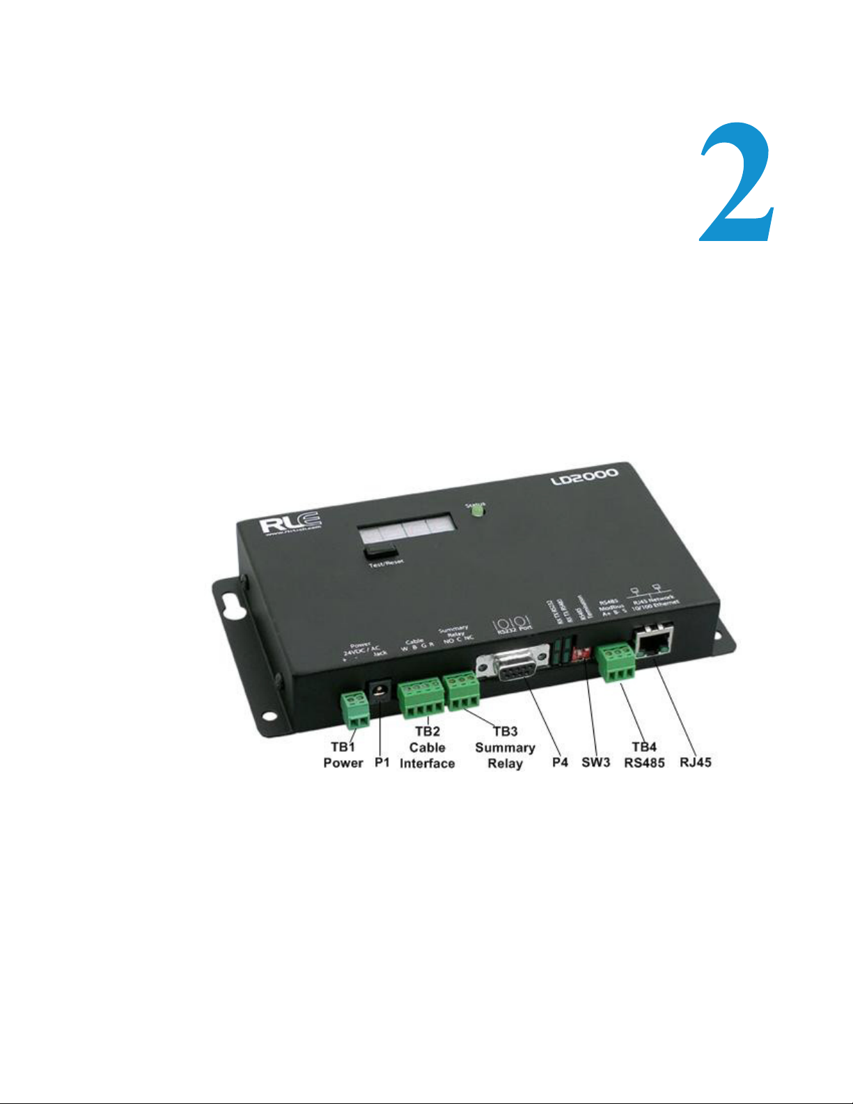
The LD2000 contains one circuit board. All connections are accessible when the unit is inside
of its enclosure. The connectors on the main board, found at the bottom of Figure 2.1, are
labeled TB1 through TB4 and P1 through P4.
Figure 2.1
www.rletech.com 17 970.484.6510
LD2000 Connections
Page 18

2 Connections and Settings
2.1. Reset
When held this button will reset the unit and clear any alarms. The LD2000 will then recheck
for any alarm conditions.
2.2. Connections
2.2.1 TB1: Input Power
This is an optional two position connector—you may also use P1 for input power—with the
following connections:
TB1-1 24VDC positive (+)
TB1-2 24VDC negative (-)
2.2.2 P1: Input Power
This is an optional barrel connection for input power-you may also use TB1 for input powerwith the following connection:
Inside positive (+)
Outside negative (-)
Power is recommended to be supplied by a 24VDC wall adapter power supply (part
#WA-DC-24-ST), which is not included with the LD2000 and can be purchased separately.
For more information on RLE power supplies, visit the SeaHawk Accessories webpage at
www.rletech.com, or contact RLE.
2.2.3 TB2: Cable Interface
The SeaHawk Water Leak Detection Cable (sensing cable) connects to TB2. A 15 foot
(4.57m) non-sensing leader cable is required to connect the LD2000 to the sensing cable. The
non-sensing cable is included in a leader cable kit (part #LC-KIT; purchased separately).
Connect the cable wires to TB2 as follows:
TB2-1 White wire
TB2-2 Black wire
TB2-3 Green wire
TB2-4 Red wire
www.rletech.com 18 970.484.6510
Page 19

2 Connections and Settings
2.2.4 TB3: Summary Relay
Terminal TB3 is a Form C Relay Output. This relay provides alarm notification when a leak is
detected, a cable fault is detected, or a cable contamination is detected.
The three contacts on TB3 are labeled NO, C, and NC. Connect the alarm relay wires to TB3
as follows:
TB3-1 Leak alarm normally open (NO)
TB3-2 Leak alarm common (C)
TB3-3 Leak alarm normally closed (NC)
Both relays (all alarms) can be configured to be latched or unlatched. A latched alarm requires
a manual reset of the system once a leak or cable problem is no longer present; see 4.3.1,
“Leak Settings” on page 33 for configuration instructions.
2.2.5 P4: EIA-232 Connector
The EIA-232 uses a baud rate of 9600. The EIA-232 port is set to 8 databits, no parity, and 1
stop bit (8, N, 1). A straight through cable should be used to connect a terminal or PC to the
LD2000. This connection should only be used for setting the IP address, advanced diagnostics,
uploading firmware, and troubleshooting.
2.2.6 SW3: EIA-485 Termination
Switch SW3, when switched on (down position), places a termination resistor across the + and
- terminals of the EIA-485 port. This is used when the LD2000 is the last unit on a EIA-485
network.
2.2.7 TB4: EIA-485 Modbus Port
TB4 connects to a EIA-485 network. A grounded shield contact is provided for connection to
shielded cable. If the shield contact is used, verify the power connector is properly grounded
and there is no voltage potential between units on the network.The EIA-485 port is set to 8
databits, no parity, and 1 stop bit (8, N, 1). Connect the EIA-485 wires to TB4 as follows:
TB3-1 A (+)
TB3-2 B (-)
TB3-3 Shield
2.2.8 P3: RJ45 Network
A 10/100 BaseT Ethernet connection is available to connect the LD2000 on a local area
network. Use a crossover cable (shipped with the LD2000; blue cable with yellow ends) for
initial connection and configuration. The default settings are as follows:
IP Address: 10.0.0.188
Subnet Mask: 255.255.255.0
www.rletech.com 19 970.484.6510
Page 20

2 Connections and Settings
Notes:
www.rletech.com 20 970.484.6510
Page 21
3.1. Installing the LD2000
The LD2000 is a wall mounted device. The four mounting holes on the sides of the unit are
spaced 7.5 inches (.19m) apart. Use drywall anchors if securing the unit to drywall.
C HAPTER
CHAPTER 0INSTALLATION
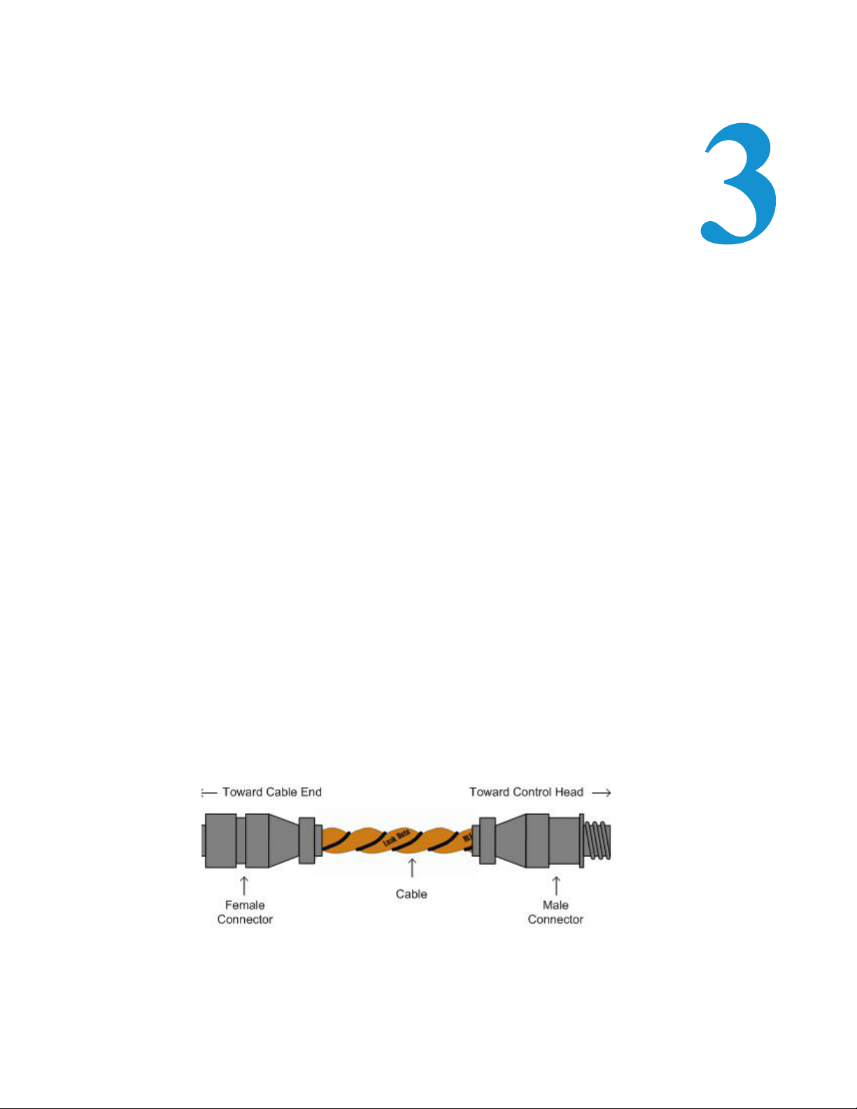
3.2. Connecting the SeaHawk Leak Detection Cable
The LD2000 is shipped with a 15-foot (4.57m) leader cable. One end of this leader cable
connects to the LD2000 controller, and the other end connects to the SeaHawk leak detection
cable (sensing cable). Connect each end of the leader cable as follows:
1 With the screws of the terminal block connector on the LD2000 facing up, connect the four
stripped, bare wires of the leader cable to the terminals in this order, from left to right:
white, black, green, red.
Note If the terminal connector is removed from the end of the cable, make sure the wires are in
this same order when the connector is reapplied.
2
Unscrew the end-of-line (EOL) terminator from the other end of the leader cable.
3 Attach the first length of leak detection cable (sensing cable) to the leader cable.
Figure 3.1
www.rletech.com 21 970.484.6510
SeaHawk Water Leak Detection Cable (Sensing Cable)
Page 22

3 Installation
WARNING
4 Route the sensing cable according to a cable layout diagram, if provided.
5 Secure the EOL terminator on the unoccupied end of the sensing cable.
3.2.1 Securing Cable to the Floor
Secure the sensing cable to the floor with either J-clips (part #JC), or one of the other approved
methods shown in Figure 3.2. Available from RLE and designed specifically for use with
sensing cable, J-clips (part #JC) are the manufacturer's recommended installation method and
can be installed as follows:
Place one J-clip every 5 to 6 feet (1.52 to 1.83m) along the length of the sensing cable and
one at each turn of the cable. Use more J-clips if a “tighter” configuration is required.
If the cable is installed over an obstruction, clip the cable on both sides, as close to the
obstruction as possible.
Do not install the cable directly in front of an air conditioner. Allow a minimum of 4
to 6 feet (1.22 to 1.83m) between the unit and the cable. If the cable is too close to
the air conditioning unit’s air stream, the moisture from the humidifier may cause
false leak readings. If the cable must be installed in front of an air conditioning
unit, place the J-clips 12 to 18 inches (.305 to .457m) apart.
Finish the end of the SeaHawk leak detection cable (sensing cable) with the end terminator
(EOL) that is shipped with the LD2000. If the EOL terminator is not present, a cable fault
will register. Note any variances between the cable layout diagram and the actual cable
installation.
Figure 3.2
www.rletech.com 22 970.484.6510
Cable Installation Methods
Page 23

3.2.2 Applying Power to the LD2000
Once the SeaHawk leak detection cable (sensing cable) is connected to the unit, power can be
applied. The LD2000 operates on 24VDC or 24VAC power. A power supply is not included
with the LD2000. RLE recommends its 24VDC power supply (part #PSWA-DC-24), which
can be purchased separately. For more information on RLE power supplies, visit
www.rletech.com, or contact RLE.
Note RLE recommends that an isolated power supply be used.
Before applying power to the unit, ensure all cable and communication connections are
complete. The LD2000 begins booting once power is applied. Wait approximately one minute.
No alarm should be present.
On the webpage interface, the cable length is displayed. If this reading varies by more than
±5% of the actual length of cable installed, verify the installation. The LD2000 should not
require any calibration. If any calibration is required, verify that the cable current is zero
before calibrating or false, inaccurate readings will occur.
Through the webpage submenus, you may set the clock, system name, alarm configuration,
feet/meters, etc.
3 Installation
www.rletech.com 23 970.484.6510
Page 24
3 Installation
3.2.3 Communication
IMPORTANT Consult your IT administrator before performing these steps.
3.2.3.1 Accessing the Configuration Menu
You will use the Configuration Menu to configure communications for the LD2000.
1 Plug the crossover cable (included with the LD2000) into the computer that will be used to
configure the LD2000.
Note This cable is not intended to be connected to a network hub.
Connect the other end of the crossover cable to the Ethernet port on the back of the
2
LD2000.
Note Alternatively, you could use the LD2000’s EIA-232 interface to access the LD2000. Refer to
the LD2000 User Guide (available at
http://www.rletech.com) for instructions.
3
Write down the computer’s current IP address, subnet mask, and default gateway. Change
these items temporarily so that the computer can communicate with the LD2000.
LD2000 default IP address: 10.0.0.188
LD2000 default subnet mask: 255.255.255.0
4 Access the LD2000 through a Web browser by typing the LD2000’s default IP address
(10.0.0.188) into the location bar and pressing Enter.
5 Enter the following:
Default User Name: ld2000 (case sensitive)
Default Password: (No default password. Leave this field blank.)
Once you enter this information, the home page for the LD2000’s web interface displays.
6 Continue to the following section to configure network communication for the LD2000.
www.rletech.com 24 970.484.6510
Page 25

3 Installation
Select Network Settings
3.2.3.2 Configuring Network Communication
1 From the home page of the LD2000’s web interface, select the Configuration Menu link.
Then, select Network/IP Settings from the Configuration Menu.
www.rletech.com 25 970.484.6510
Page 26

3 Installation
LD2000 Default Values
IP address: 10.0.0.188
Subnet mask:
Use values provided
by IT administrator
The Network/IP Configuration page displays.
2 Enter the values for IP Address, Net Mask (subnet mask), and Def Route (default gateway)
provided by your IT administrator.
Once you enter the values and click the Submit Changes button, the LD2000 saves the
changes and reboots. The system status LED on front of the LD2000 stops flashing.
3 Reset the computer to its original IP address and subnet mask.
Note This step might require assistance from your IT administrator.
The computer and the LD2000 are now both configured to communicate on the network.
4 From the computer’s Web browser, go to the new IP address of the LD2000.
5 When prompted, enter the user name and password to verify network access to the LD2000
(as you did in step 4 in the previous section).
If the login window for the LD2000 does not display:
a Verify that the cables are firmly attached.
b Verify that you entered the correct IP address for the LD2000.
c Verify that the Status light on the top of the LD2000 is green.
For troubleshooting and additional configuration information, consult the LD2000 User Guide
available at www.rletech.com
www.rletech.com 26 970.484.6510
Page 27

3 Installation
Set the LD2000's IP Address using an EIA-232 Connection
To use the EIA-232 interface:
1 Connect the EIA-232 port (P4) on the LD2000 to a terminal or PC running terminal
emulation software (HyperTerminal) with a 9-pin male-female straight through serial cable.
6 2. Set the appropriate communication port to 9600 baud, NO parity, 8 data bits, 1 stop
bit, (9600/N/8/1), and no software or hardware flow command.
7 Once the terminal emulation software starts, type ? and press Enter on the keyboard and the
Main Menu should appear. If the Main Menu does not appear, check the communication
settings and make sure the unit is powered on.
8 From the Main Menu type netcfg to select the Network Configuration Menu.
9 Enter the new IP address for the LD2000 by typing ip xxx.xxx.xxx.xxx where
xxx.xxx.xxx.xxx is the new IP address of the unit. Separate each field with a decimal point.
For example, type ip 10.0.0.50 <enter>.
The LD2000 erases a memory block and copies data to flash memory before rebooting.
The LD2000 IP address is now set and the LD2000 can be accessed through a Web
browser using the new IP address.
10Repeat steps 8–9 to change the Subnet Mask and Def Route, if needed, using the commands
nm xxx.xxx.xxx.xxx to change the Subnet Mask and dg xxx.xxx.xxx.xxx to change the
default gateway.
www.rletech.com 27 970.484.6510
Page 28

3 Installation
Notes:
www.rletech.com 28 970.484.6510
Page 29

C HAPTER
CHAPTER 0WEB INTERFACE
The LD2000's network connection allows users to configure and view current information
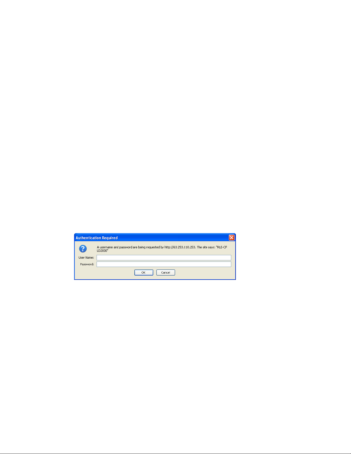
from the LD2000. To log in to the LD2000:
1 Navigate to the unit's IP address in a Web browser.
A login prompt asks for a username and password.
2 Enter in the appropriate information.
Default Settings:
IP: 10.0.0.188
Username: ld2000
Password: (leave this field blank)
Figure 4.1
LD2000 Log In Prompt
www.rletech.com 29 970.484.6510
Page 30

4 Web Interface
4.1. Home
When logging into the LD2000, the first page display is the Home page. All vital information
is display in the main table. From the main page, four links are available in the top right
section: Refresh, Home, Historical Data, and Configuration. Refresh allows the user to refresh
the webpage and update all data in the table. Home is a link to the Home page currently being
viewed. Historical Data and Configuration are links to their appropriate webpages.
Figure 4.2
LD2000 Home Page0
www.rletech.com 30 970.484.6510
Page 31

4.2. Historical Data
The Historical Data page displays a table of Alarm History and also provides a link to the
Trend Log (located in the upper right). The Alarm History table displays Alarms and events
recorded in the unit's memory log. The alarms are displayed as follows:
AHxxx-yy-zzz – DATE TIME DESCRIPTION
xxx is the log entry number for the alarm/event.
yy is the event code and varies depending on the event (03 - Cable Fault, 04 - Leak
Detected, 05 - Contamination Detected, 06 - Reset/Power Up)
DATE and TIME are displayed as MM/DD/YY and HH:MM:SS (24 hour) format.
DESCRIPTION provides details about the current alarm/event.
4 Web Interface
Figure 4.3
www.rletech.com 31 970.484.6510
Historical Data Page
Page 32

4 Web Interface
4.2.1 Trend Log
The Trend Log option provides a trending list of logged current leakage. This provides
assistance in troubleshooting leaks and inaccurate readings.
Figure 4.4
Trend Log
www.rletech.com 32 970.484.6510
Page 33

4.3. Configuration
The Configuration page gives access to a menu of available settings.
4 Web Interface
Figure 4.5
Configuration Main Menu
4.3.1 Leak Settings
The Leak Settings menu displays all current leak and cable settings.
Table 4.1
Leak Settings Menu
Option Description
Leap Trip Point The amount of current leakage required to detect a leak. Default
Contamination Trip
Point
Leak Alarm Delay The amount of time required to pass once the Leak Trip Point has
Contamination
Alarm Delay
Link Settings Menu Settings
setting is 150uA. Adjust this number to adjust the sensitivity of the
leak detection cable to leaks (higher = less sensitive, lower = more
sensitive).
The amount of current leakage required to detect cable
contamination. Default setting is 50uA. Adjust this number to adjust
the sensitivity of the leak detection cable to contamination (higher =
less sensitive, lower = more sensitive).
been reached before declaring a leak alarm. The Leak Trip Point
must also be exceeded for the duration of the delay.
The amount of time required to pass once the Contamination Trip
Point has been reached before declaring a contamination alarm.
The Contamination Trip Point must also be exceeded for the
duration of the delay.
www.rletech.com 33 970.484.6510
Page 34

4 Web Interface
Table 4.1
Link Settings Menu Settings (continued)
Leak Settings Menu
Option
Description
Resistance Per Foot The resistance per foot (or meter) of cable determines the unit's
ability to accurately detect the cable length installed and calculate
distances to leaks. The default setting is 2.800 ohms and should
not be changed for any RLE cable; parts SC-10, SC-25, SC-50, and
SC-100 are all built to specifications of 2.8 ohms per foot.
Measurement
Display
The type of units that are displayed on the LD2000. Select either
feet or meters to calibrate the unit to the preferred unit of measure.
Latching Alarms This option selects the latching ability for the alarm notifications of
the unit. Latching alarms will hold the unit in an alarm state, even
after the condition has been cleared, until someone presses the
Reset button, located on the front of the physical LD2000 unit.
Figure 4.6
www.rletech.com 34 970.484.6510
Latching Alarms/Leak Configuration
Page 35

4.3.2 Zone Configuration
4 Web Interface
Table 4.2
Zone
Configurations
Settings
Zones 1- 8 Allows users to set zones to be virtual or physical points. Virtual is
Modbus Zone Traps You can enable or disable SNMP traps for the Leak Detection
Enable Alarm Relay
for Modbus Slaves
Zone Links There is a link for a reference map to the LD2000. A link has been
Zone Configuration Menu Settings
Description
used for labeling reference points along the leak detection cable
length. Physical is for when using the LD2000 as a Leak Detection
Modbus master. Physical points are described in Appendix B.
Modbus master.
The summary alarm can also be activated when a Leak Detection
slave unit goes into an alarm.
provided for every potential slave unit that may be attached.
Figure 4.7
Figure 4.8
Zone Configuration
Link Configuration Page
www.rletech.com 35 970.484.6510
Page 36

4 Web Interface
4.3.3 Zone 1-8 Settings
Virtual Zones will display in the descriptions of any leak alarm when detected in the
appropriate cable range. Labeling zone descriptions increases the speed in which a leak is
physically discovered. For example, a section of cable located in the “Room A” might be
labeled “Rm. A.” Because the description refers to a familiar location rather than cable
distance, the alarm can be located faster. Each zone begins with previous zone's end distance
and ends with its own. Zone 1 begins at zero.
See Appendix B, “Leak Detection Modbus Master” on page 65 if using the LD2000 for Leak
Detection Modbus Master. Appendix B describes the Physical/Modbus/485 for settings 1-8
and settings 9-16.
4.3.4 Network Settings/ IP Configuration
The Network settings allow users to change the network configuration of the LD2000. IP
address, Subnet Mask, and Default Route (Gateway) may be changed from this menu.
Figure 4.9
IP Configuration
www.rletech.com 36 970.484.6510
Page 37

4 Web Interface
4.3.5 Web Settings/ Configuration
The Web Settings menu allows users to set two different security level passwords on the
LD2000. A Read-Only level password allows users to view only the information and settings
of the LD2000. No settings or changes may be submitted to the unit.
The Read/Write level password allows users to change settings and configurations on the
LD2000 and view all information in the unit. The Web refresh rate changes the interval that
the Home page refreshes automatically when left open in an Internet browser. The link URL
allows a user to link a file of a reference map to the webpage interface. Use a file common to
all users, such as a .jpg or .pdf.
Figure 4.10
Web Configuration
www.rletech.com 37 970.484.6510
Page 38

4 Web Interface
4.3.6 Email/DNS
The Email page allows users to configure the LD2000 to send notification via email when the
unit is in an alarm state. The LD2000 will send one email message per alarm instance to a
maximum of four email recipients.
Table 4.3
Email Menu Options Description
Access Type Specifies whether to send the message through a local network
Email
Contamination
Alarms
DNS Servers Information provided by your ISP; needed to deliver the email
Mail (SMTP) Server Specifies the email server used to receive and send mail.
Mail Sender Address The address displayed in the “From” field of the email message.
Mail Subject Displayed in the subject field of the received email messages.
Mail Recipient (1) Mail Recipient (4)
SMTP
Authentication
SMTP User Name Used for ESMTP; use the recommended default setting unless
SMTP Password Used for ESMTP; use the recommended default setting unless
Email Menu Options
connection or disable the email feature (none).
Specifies whether to send email alarm notification upon a cable
contamination alarm. Users may want to disable this feature if false
alarms are often detected.
message.
Enter the addresses of up to four email recipients.
Used for ESMTP; use the recommended default setting unless
instructed differently by your IT Department.
instructed differently by your IT Department.
instructed differently by your IT Department.
www.rletech.com 38 970.484.6510
Page 39

4 Web Interface
Figure 4.11
E-mail Configuration Page
www.rletech.com 39 970.484.6510
Page 40

4 Web Interface
4.3.7 NTP (Network Time Protocol)
Network Time Protocol (NTP) is widely used in the Internet to synchronize computer clocks
to national standard time or Coordinated Universal Time (UTC). It synchronizes the time of a
computer or server (in this case, the LD2000) to another server or reference time source. NTP
is important in maintaining a high level of accuracy and reliability in time stamped events.
This page allows users to configure the LD2000's NTP feature.
Table 4.4
NTP Menu Options
Network Time (NTP)
Server
Update Interval The time, in minutes, the LD2000 will take to request time updates
Retry Interval The time in seconds the LD2000 waits before retrying a failed
Select Time Zone Enter the time zone in which the LD2000 resides.
Daylight Savings
Time
DST Begin Date Enter the date Daylight Savings Time will begin.
DST End Date Enter the date Daylight Savings Time will end.
NTP Menu Options
The IP address or hostname of the Network Time Protocol Server
with which the LD2000 will synchronize. Examples of public NTP
Servers include “us.pool.ntp.org” and “time.nist.gov”.
from the NTP Server. This can be set from 5-1440 minutes. Enter 0
to disable.
connection to the NTP Server. This can be set from 10-120
seconds.
Select the hour Daylight Savings Time occurs. Typically, this is 2:00
A.M. local time.
Figure 4.12
www.rletech.com 40 970.484.6510
Network Time Protocol (NTP) Configuration
Page 41

4.3.8 SNMP/Syslog
SNMP/Syslog allows users to configure SNMP notification options.
4 Web Interface
Table 4.5
SNMP/Syslog Menu
Options Description
System Name Appears on the LD2000 Main Menu and is included as part of email
System Contact Lists the individual responsible for the LD2000. The System
System Location Lists the location of the LD2000. The System Location is not
Select SNMP Trap
Type
Max Inform Retries The number of times the LD2000 will retry an Inform operation
Inform Interval The amount of time, in minutes, between Inform operations.
V1/V2C Community
Names
Trap Communities Identifies devices that receive SNMP Traps and/or Syslog
SNMP/Syslog Menu Options
notifications.
Contact is only available through SNMP Gets and is not included in
email or SNMP Trap notifications.
included in email or SNMP Trap notifications.
Choose from three trap types:
V1-Trap
V2C-Trap
V2C-Inform
when the original Inform is unacknowledged.
The community name of the manager.
messages from the LD2000 and interacts with the LD2000 over the
network. To add a device to the Communities list, select a
community number posted as “empty.” Enter the receiving device's
IP Address and a string that identifies the device. An IP Address of
0.0.0.0 in this field allows any device to access the LD2000 through
an MIB browser. Select “Write” if the device will have Read/Write
network access. This allows the LD2000 to be configured over the
network. Select “Trap” if the device will receive Traps from the
LD2000. Select “Syslog Messages” if the device will receive Syslog
messages from the LD2000.
www.rletech.com 41 970.484.6510
Page 42

4 Web Interface
Figure 4.13
SNMP/Syslog Configuration
www.rletech.com 42 970.484.6510
Page 43

4 Web Interface
4.3.9 Modbus
Modbus Configuration allows users to configure Modbus (EIA-485 and/or TCP/IP) options.
//anything about N2 needed here?//
Table 4.6
Modbus
Configuration Menu
Options
Modbus/TCP Slave
Unit Identifier
EIA-485 Port
Function
LCD-240 Option The LCD option refers to the text that will be displayed on the LDC
Modbus Configuration Menu Options
Description
Specify the slave address used on the LD2000's IP port (1-254).
Allows users to select the function of the EIA-485 port. Selecting
this option tells the LD2000 whether it is a Modbus Slave (this is the
default, and most typical selection), a BACnet-MS/TP Slave, a
Modbus Master (for when the LD2000 is acting as a Modbus
Master for other RLE leak Detection Panels), or an LCD-240 (this is
a specialized option and is not typically used; see below for
configuration details).
screen of the LD2000. The number, 240, references the amount of
text allowed for each label-2 lines of text, with 40 characters each.
After selecting the LCD-240 display option, click the submit
changes button. When the page refreshes there will be eight fields
to configure:
• LCD240 Identifier-the system name.
• LCD240 Normal Text-the text that will appear when the LD2000
is in a normal state.
• LCD240 Alarm Text- the text that will appear when the LD2000
is in an alarm state.
• LCD240 Leak Text- the text that will appear when the LD2000
detects a leak.
• LCD240 Cable Break Text- the text that will appear when the
LD2000 detects a cable break.
• LCD240 Contamination Text- the text that will appear when the
LD2000 detects a cable contamination.
Enter a time unit in the LCD240 Refresh Interval field to set the time
interval for the screen to update. Check the LCD240 Refresh on
Alarms only to have the display refreshes only when an alarm is
triggered; see Figure 4-14: LCD-240 Option on page 18.
EIA-485 Baud Rate Sets the EIA-485 Port to 1200, 2400, 9600, 19200, or 38400 baud.
All the devices connected to the Modbus network must be set to
operate at the same baud rate.
Note: The baud rate for Modbus N2 is always 9600 and cannot be
changed.
EIA-485 Parity Sets the EIA-485 Port to None, Even or Odd Parity. All the devices
connected to the Modbus network must be set to operate at the
same parity.
Note: The parity for Modbus N2 is always None and cannot be
changed.
EIA-485 Slave
Address
www.rletech.com 43 970.484.6510
Set the EIA-485 Port's slave address (1-254). Each device on the
EIA-485 Modbus network must have a unique address.
Page 44

4 Web Interface
Figure 4.14
www.rletech.com 44 970.484.6510
LCD-240 Option
Page 45

4 Web Interface
Figure 4.15
Modbus/EIA-485 Configuration (Johnson N2 Shown)
4.3.10 BACnet
The BACnet Configuration page allows the user to enable the LD2000 for BACnet slave
configuration.
Table 4.7
BACnet
Configuration Menu
Options
BACnet Device
Name
BACnet Device ID The unique identifier for the LD2000 on the BACnet network.
BACnet Description The description of the LD2000 as it will appear on the BACnet
BACnet UDP Port The port to which the LD2000 will respond to BACnet requests. The
BACnet Configuration Menu Options
Description
The name of the LD2000 as it will appear on the BACnet network.
network.
default number of zero in this field will configure the LD2000 to
listen on the standard BACnet port of 47808, see the BACnet
standard for more information.
BACnet MS/TP Max
Master
BACnet BBMD-BDT,
LD2000 IP Address,
#1 IP Address, #2 IP
Address, #3 IP
Address, #4 IP
Address
www.rletech.com 45 970.484.6510
The highest allowable address for master nodes on the MSTP
network.
These fields give the user a reference and edit capabilities of the
BACnet Broadcast Distribution Table. These fields DO NOT need
to be configured by the user. If the LD2000 is acting as a BACnet
router, these fields will automatically be populated by the BACnet
network controller.
Page 46

4 Web Interface
Figure 4.16
www.rletech.com 46 970.484.6510
BACnet Configuration
Page 47

4 Web Interface
4.3.11 Clock
The Clock Configuration page allows users to set the date and time on the LD2000's internal
clock.
Enter the date using a MM/DD/YY format, where MM is a two digit month, DD is a two
digit day, and YY is a two digit year.
Enter the time using a HH/MM/SS format, where HH is a two digit hour (1-24), MM is a
two digit minute (1-60), and SS is a two digit second (1-60).
Figure 4.17
Clock Configuration Page
4.3.12 Alarm Management
The Alarm Management page allows users to acknowledge, reset, and clear alarms.
Table 4.8
Alarm Management
Menu Options Description
Acknowledge SNMP
Informs
Reset Leak Alarm Resets the current leak alarm and causes the unit to recheck the
Clear Alarm History Clears the alarm history table of all previous alarms.
Alarm Management Menu Options
Acknowledges SNMP Informs and ceases Informs from being sent
out for the current alarm condition.
current cable conditions. This will clear the alarm condition if the
cable registers that the leak threshold is within an accepted range.
Figure 4.18
www.rletech.com 47 970.484.6510
Alarm Management Configuration
Page 48

4 Web Interface
4.3.13 System Management
The System Management page allows users to restore the unit to factory default settings and
upload firmware.
Table 4.9
System
Management Menu
Options
Exit to Bootloader Forces the unit to stop running flash application to allow for
Restore Factory
Defaults
System Management Menu Options
Description
firmware updates; see Appendix A, “Firmware Updates” on
page 59, for more information.
Resets the configurations and settings on the unit to all factory
defaults.
Figure 4.19
www.rletech.com 48 970.484.6510
System Management Page
Page 49

4 Web Interface
Figure 4.20
Exit to Bootloader Page
www.rletech.com 49 970.484.6510
Page 50

4 Web Interface
Notes:
www.rletech.com 50 970.484.6510
Page 51

CHAPTER 4MODBUS COMMUNICATION
This chapter describes the Modbus communication protocol as supported by the LD2000
Distance Read System. The content includes details and information on how to configure the
LD2000 for communications via Modbus network
5.1. Implementation Basics
C HAPTER
The LD2000 is capable of communicating via the half-duplex EIA-485 serial communication
standard. The LD2000 is configured to act as a slave device on a common network. The EIA485 medium allows for multiple devices on a multi-drop network. The LD2000 is a slave only
device and will never initiate a communications sequence.
5.1.1 Modes of Transmission
The Modbus protocol uses ASCII and RTU modes of transmission. The LD2000 supports only
the RTU mode of transmission, with 8 data bits, no parity and one stop bit. Every Modbus
packet consists of four fields:
Slave Address Field
Function Field
Data Field
Error Check Field (Checksum)
5.1.1.1 Slave Address Field
The slave address field is one byte in length and identifies the slave device involved in the
transaction. A valid address range is between 1 and 254. The slave address is set from the
Modbus/EIA-485 Configuration webpage (see 4.3.9, “Modbus” on page 43).
www.rletech.com 51 970.484.6510
Page 52

5 Modbus Communication
5.1.1.2 Function Field
The function field is one byte in length and tells the LD2000 which function to perform. The
supported functions are 03 (Read 4xxxx output registers), 04 (Read 3xxxx input registers), 06
(Preset single register) and 16 (Preset multiple registers).
5.1.1.3 Data Field
The data field of the request is a variable length depending on the function. The data fields for
the LD2000 are 16-bit registers, transmitted high order byte first (big-endian).
5.1.1.4 Error Check (Checksum) Field
The checksum field lets the receiving device determine if the packet has transmission errors.
The LD2000 RTU mode uses a 16-bit cyclic redundancy check (CRC-16).
5.1.1.5 5-1.2 Exception Responses
If a Modbus master sends an invalid command to the LD2000 or attempts to read an invalid
register, an exception response is generated. The response packet will have the high order bit
of the function code set to one. The data field of the exception response contains the exception
error code.
Table 5.1
Code Name Description
01 Illegal Function The function code is not supported
02 Illegal Data Address Attempt to access an invalid address
03 Illegal Data Value Attempt to set a variable to an invalid value
Exception Codes
www.rletech.com 52 970.484.6510
Page 53

5 Modbus Communication
5.2. Packet Communications for the LD2000
This section covers the registers with the name and a brief description of each.
5.2.1 Function 03: Read Output Registers
To read the LD2000 parameter values, the master must send a Read Output Registers request
packet.
The Read Output Registers request packet specifies a start register and the number of registers
to read. The start register is numbered from zero (40001 = zero, 40002 = one, etc).
Table 5.2
Read Registers Request Packet Read Registers Response Packet
Slave Address (1 byte) Slave Address (1 byte)
03 (Function code) (1 byte) 03 (Function code) (1 byte)
Start Register (2 bytes) Byte count (1 byte)
# of registers to read (2 bytes) First register (2 bytes)
Crc Checksum (2 bytes) Second register (2 bytes)
Table 5.3
Register Name Description Units Range
40001 Leak Threshold Trip current for leak alarm 25-295 uAmps 0-65535
40002 Contamination
40003 Spare 0-65535
40004 Spare 0-65535
Output Registers
Threshold
Read Output Register Packet Structure
…
Crc Checksum (2 bytes)
Trip current for
contamination alarm
20-295 uAmps 0-65535
40005 Spare 0-65535
40006 Spare 0-65535
40007 Spare 0-65535
40008 Spare 0-65535
40009 Spare 0-65535
40010 Spare 0-65535
40011 Spare 0-65535
40012 Spare 0-65535
40013 Spare 0-65535
40014 Spare 0-65535
www.rletech.com 53 970.484.6510
Page 54

5 Modbus Communication
Table 5.3
Register Name Description Units Range
40015 Spare 0-65535
40016 Leak Alarm Delay Leak Alarm Delay 5-995 seconds 0-65535
40017 Contamination Alarm
Output Registers (continued)
Delay
Contamination Alarm
Delay
5-995 seconds 0-65535
5.2.2 Function 04: Read Input Registers
To read the LD2000 input values, the master must send a Read Input Registers request packet.
The Read Input Registers request packet specifies a start register and the number of registers
to read. The start register is numbered from zero (30001 = zero, 30002 = one, etc).
Table 5.4
Read Registers Request Packet Read Registers Response Packet
Slave Address (1 byte) Slave Address (1 byte)
04 (Function code) (1 byte) 04 (Function code) (1 byte)
Read Input Registers Packet Structure
Start Register (2 bytes) Byte count (1 byte)
# of registers to read (2 bytes) First register (2 bytes)
Crc Checksum (2 bytes) Second register (2 bytes)
…
Crc Checksum (2 bytes)
Table 5.5
Register Name Description Units Range
30001 Status Bit level status None 0-65535
30002 Leak Distance Location of leak Ft/Meters 0-65535
30003 Units Unit of measure 1=Ft 0=Meters 0-65535
30004 Leak Current Leakage current on cable uAmps 0-65535
30005 Cable Length Installed cable length Ft/Meters 0-65535
30006 Loop1 Res Resistance of cable Ohms 0-65535
30007 Loop2 Res Resistance of cable Ohms 0-65535
30008 Res/Ft Resistance of cable Ohms x1000 0-65535
Input Registers
30009 Version Firmware version xx.xx X 100 0-65535
30010 Virtual Zone Alarm Status Bit Level Status None 0-65535
30011 Modbus Zone Enabled Flags Bit Level Status None 0-65535
30012 Modbus Zone2 Status Bit Level Status None 0-65535
www.rletech.com 54 970.484.6510
Page 55

5 Modbus Communication
Table 5.5
Input Registers (continued)
Register Name Description Units Range
30013 Modbus Zone2 Distance Location of leak Ft/Meters 0-65535
30014 Modbus Zone3 Status Bit Level Status None 0-65535
30015 Modbus Zone3 Distance Location of leak Ft/Meters 0-65535
30016 Modbus Zone4 Status Bit Level Status None 0-65535
30017 Modbus Zone4 Distance Location of leak Ft/Meters 0-65535
30018 Modbus Zone5 Status Bit Level Status None 0-65535
30019 Modbus Zone5 Distance Location of leak Ft/Meters 0-65535
30020 Modbus Zone6 Status Bit Level Status None 0-65535
30021 Modbus Zone6 Distance Location of leak Ft/Meters 0-65535
30022 Modbus Zone7 Status Bit Level Status None 0-65535
30023 Modbus Zone7 Distance Location of leak Ft/Meters 0-65535
30024 Modbus Zone8 Status Bit Level Status None 0-65535
30025 Modbus Zone8 Distance Location of leak Ft/Meters 0-65535
30026 Modbus Zone9 Status Bit Level Status None 0-65535
30027 Modbus Zone9 Distance Location of leak Ft/Meters 0-65535
30028 Modbus Zone10 Status Bit Level Status None 0-65535
30029 Modbus Zone10 Distance Location of leak Ft/Meters 0-65535
30030 Modbus Zone11 Status Bit Level Status None 0-65535
30031 Modbus Zone11 Distance Location of leak Ft/Meters 0-65535
30032 Modbus Zone12 Status Location of leak None 0-65535
30033 Modbus Zone12 Distance Bit Level Status Ft/Meters 0-65535
30034 Modbus Zone13 Status Location of leak None 0-65535
30035 Modbus Zone13 Distance Bit Level Status Ft/Meters 0-65535
30036 Modbus Zone14 Status Location of leak None 0-65535
30037 Modbus Zone14 Distance Bit Level Status Ft/Meters 0-65535
30038 Modbus Zone15 Status Location of leak None 0-65535
30039 Modbus Zone15 Distance Bit Level Status Ft/Meters 0-65535
30040 Modbus Zone16 Status Location of leak None 0-65535
30041 Modbus Zone16 Distance Bit Level Status Ft/Meters 0-65535
Registers 30011 through 30041 are dedicated registers for modbus master; see Appendix B for details.
www.rletech.com 55 970.484.6510
Page 56

5 Modbus Communication
Table 5.6
Status Flags (Register 30001)
Bit Description
00 1 = Leak is Detected
01 1 = Cable Break Alarm
02 1 = Contamination is detected
04-15 Spare
Table 5.7
Status Flags (Register 30010)
Bit Description
00 1 = Zone1
01 1 = Zone2
02 1 = Zone3
03 1 = Zone4
04 1 = Zone5
05 1 = Zone6
06 1 = Zone7
07 1 = Zone8
Table 5.8
Status Flags (Register 30011)
Bit Description
00 1 = Not enabled
01 1 = Enabled, b1=MBZ2
02 1 = MBZ3
03 1 = MBZ4
04 1 = MBZ5
05 1 = MBZ6
06 1 = MBZ7
07 1 = MBZ8
08 1 = MBZ9
09 1 = MBZ20
10 1 = MBZ11
11 1 = MBZ12
12 1 = MBZ13
13 1 = MBZ14
www.rletech.com 56 970.484.6510
Page 57

5 Modbus Communication
Table 5.8
Bit Description
14 1 = MBZ15
15 1 = MBZ16
Table 5.9
Bit Description
00 1= Leak Alarm
01 1 = Cable Break
02 1 = Contamination Alarm
07 1 = Communication Loss
Status Flags (Register 30011) (continued)
Status Flags (Even Registers 30012-30040)
5.2.3 Function 06: Preset Single Register
To set a LD2000 parameter value, the master must send a Preset Single Register request
packet. The Preset Single Register request packet specifies a register and the data to write to
that register. The register is numbered from zero (40001 = zero, 40002 = one, etc).
Table 5.10
Preset Register Request Packet Preset Register Response Packet
Slave Address (1 byte) Slave Address (1 byte)
06 (Function code) (1 byte) 06 (Function code) (1 byte)
Register (2 bytes) Register (2 byte)
Data (2 bytes) Data (2 bytes)
Crc Checksum (2 bytes) Crc Checksum (2 bytes)
Preset Single Register Packet Structure
www.rletech.com 57 970.484.6510
Page 58

5 Modbus Communication
5.2.4 Function 16: Preset Multiple Registers
To set multiple LD2000 parameter values, the master must send a Preset Multiple Registers
request packet. The Preset Multiple Register request packet specifies a starting register, the
number of registers, a byte count and the data to write to the registers. The register is
numbered from zero (40001 = zero, 40002 = one, etc).
Table 5.11
Preset Registers Request Packet Preset Registers Response Packet
Slave Address (1 byte) Slave Address (1 byte)
16 (Function code) (1 byte) 16 (Function code) (1 byte)
Start Register (2 bytes) Start Register (2 bytes)
# of registers to write (2 bytes) # of registers (2 bytes)
Byte Count (1 byte) Crc Checksum (2 bytes)
Data (2 bytes)
…
…
Crc Checksum (2 bytes)
Preset Multiple Registers Packet Structure
5.3. RTU Framing
The example below shows a typical Query/Response from an LD2000 module.
Table 5.12
Response Sample
Register
Slave
Address
02 04 06 00 00 00 00 00 01 B5 A3
Function
Code
Count Bytes
of Data
Data
Msb Lsb
Register
Data
Msb Lsb
Register
Data
Msb Lsb
CRC
16
“Lsb”
CRC
126
“Msb”
Slave address 2 responds to Function Code 4 with six bytes of hexadecimal data and ends with
CRC16 checksum.
Register Values:
40001 = 0000 (hex)
40002 = 0000 (hex)
40003 = 0001 (hex)
www.rletech.com 58 970.484.6510
Page 59

A PPENDIX
CHAPTER 0FIRMWARE UPDATES
Firmware updates are available on the Resources page of our Web site at www.rletech.com.
Download appropriate firmware to an accessible place to load it to the LD2000 using a LAN
connection.
The instructions in this appendix describe how to load firmware using the LD2000’s MIME
(Multipurpose Internet Mail Extensions) feature. As an alternative, instructions are provided
for using TFTP (Trivial File Transfer Protocol). If you are able to use MIME //Ted, what’s the
limitation? When would I not be able to use MIME?//, it is the more efficient method.
A.1. Preliminary Steps
To load firmware to the LD2000 using either MIME or TFTP, first locate the correct
firmware:
1 Go to the RLE website Resources page at http://www.rletech.com/resources/.
2 Scroll down to the SeaHawk section and locate the firmware (a .bin file) for the LD2000.
3 Using the same filename, save the firmware to a local disk.
IMPORTANT Do not change the name of the firmware file when you save it. Otherwise, the LD2000 will not
recognize the file.
www.rletech.com 59 970.484.6510
Page 60

A Firmware Updates
A.2. Loading Flash Firmware Using MIME
To use MIME to load the firmware:
On the LD2000 interface, go to Configuration>System/Flash Management.
1
Figure A.1
2
Click the Browse button.
3 Locate and choose the firmware file (.bin) that you saved from the RLE website.
System Management Page
The path and name of the firmware file (.bin) displays in the field to the left of the Browse
button.
Figure A.2
www.rletech.com 60 970.484.6510
Choosing a Firmware File
Page 61

A Firmware Updates
4 Click the Upload button.
The firmware is loaded while the LD2000 displays a message confirming that it is loading
the new file.
Figure A.3
Firmware Load Messages
//?? The file is loaded to the Image 2 area, which is also called the Backup area. The Image
1 area (also called the Active area) contains the current flash firmware that is in use. ??//
5 To copy the firmware you just uploaded from Image 2 to Image 1 . . . , //does this work the
same way as for the FMS? These buttons are labeled differently.// The following prompt
displays:
6 Click OK to start the erase and copy process.
During this process, the following messages display:
7 If the system does not reboot on its own, click the here link to display the LD2000 Home
page.
www.rletech.com 61 970.484.6510
Page 62

A Firmware Updates
8 You can verify which firmware version is loaded by clicking the Identity link on the top bar
and looking for the field called Flash Application
Figure A.4
Current Firmware Version As Shown in LD2000 Interface
www.rletech.com 62 970.484.6510
Page 63

A.3. Loading Flash Firmware Using TFTP
Before updating the firmware, the firmware flash application must be exited and then erased.
To do this, navigate to the LD2000's System Management menu. Once here, click on the “Exit
to Bootloader” button (you must have write access to the unit in order to accomplish this task).
Once exited, you will get a bootloader webpage at the IP address of the unit. Next, click on the
“Erase Flash” button. The Flash application will be erased.
Note In order to erase the flash, a special username and password are required:
Username: ld2000 (all alowercase)
Password: rle2tech (all lowercase)
1
Uploading firmware via TFTP requires a TFTP Client. It may be possible to download a
free license TFTP Client from the internet. Consult your IT department to determine a
compatible client program.
2 Verify that your PC and the LD2000 are on the same subnetwork (LAN).
3 Open your TFTP client. Configure the client as follows.
a Host = LD2000 IP Address
A Firmware Updates
b Port = 69
c Block Size = 64, 128, 256, 512, or 1024
Note The file must be sent in BINARY (not ASCII).
4
Send or PUT the firmware file to the LD2000. It may take ~10 seconds for the firmware
upload to begin. This will put the new firmware into effect.
5 After one minute, refresh the LD2000 webpage. Notice that the Flash field now contains the
latest firmware. Click the “Start Application” button to reboot the unit.
www.rletech.com 63 970.484.6510
Page 64

A Firmware Updates
Notes:
www.rletech.com 64 970.484.6510
Page 65

A PPENDIX
CHAPTER 0LEAK DETECTION MODBUS MASTER
This feature allows the LD2000 to act as a Modbus master to other RLE distance read panels.
Up to 15 RLE distance read panels can be connected to the EIA-485 port on the LD2000. The
system status can be viewed by using the home webpage. The LD2000 will display leak, cable
break, cable contamination, and loss of communications alarms from the slave units connected
to it.
B.1. Connecting Distance Read Panels to the LD2000
(EIA-485 Port)
When using the LD2000 as a Modbus master, the slave unit(s) must be wired to the EIA-485
port (TB4). Using a two wire configuration, connect the slave units in a 485 daisy chain. You
will have to set the EIA-485 slave address in each Leak detection unit. The first unit connected
must be set to address 2. The following units will increase in numeric order by one unit (e.g.,
the next unit would be set to address 3, the following would be set to address 4, etc.; see Figure
B.1.)
Figure B.1
www.rletech.com 65 970.484.6510
LD2000 EIA-485 Connection Diagram
Page 66

B Leak Detection Modbus Master
B.2. Connecting Distance Read Panels to the LD2000
(Ethernet)
When using the LD2000 as a Modbus master, the slave unit(s) can be connected to the
LD2000 by using the local network connection, TCP/IP or UDP/IP. You will have to set the
TCP/IP, UDP/IP slave address in each Leak detection unit(s) with distance read panels that
have an Ethernet port. The first unit connected must be set to address 2 or higher. The
following units will increase in numeric order by one unit (e.g., the next unit would be set to
address 3, the following would be set to address 4, etc.; see Figure B-2.)
Set the TCP/IP, UDP/IP slave address for every distance read modules connected via the
Ethernet. The Modbus communications uses port #502 for the IP address assigned.
Figure B.2
Address Assignment for Units
www.rletech.com 66 970.484.6510
Page 67

B.3. Configuring the LD2000 Modbus
Communications
Log into the LD2000 web interface and configure the unit to be a Modbus master:
1 From the Home page, click the Configuration link in the top bar. If using the EIA-485 port,
click on EIA-485 Port/Modbus/N2.
2 Once on the Modbus/EIA-485 Configuration page, select Modbus-Master or N2 from the
Select EIA-485 Port Function drop down. When completed, click on the submit changes
tab.
B Leak Detection Modbus Master
Figure B.3
Modbus/EIA-485 Configuration (Johnson N2 Shown)
Next, configure the slave units:
3 From the LD2000 Home page, click the Configuration link in the top bar. Choose from the
following options based on the configuration you want to set up:
a To use addresses 2 through 8, choose Zone Settings???.
b If using zones 1-8 for virtual zone labeling, use Zone 9-16 Settings //what is this called
now?//.
c If you are not using the virtual zone feature, check the Physical-Modbus/485 option.
Trap notifications can be enabled or disabled on individual units via the Modbus/EIA485 Configuration page. Click the submit changes button to save changes. Return to the
Configuration screen when finished.
Figure B.4
Zone Configuration
www.rletech.com 67 970.484.6510
Page 68

B Leak Detection Modbus Master
4 For labeling Modbus/Physical zones, select Physical Zone Settings from the Configuration
Menu.
Figure B.5
Once on the menu, you can configure the labels for the slave units as follows:
5
Modbus/Physical Zone Configuration Page
If you are using the EIA-485 wiring for communication select RS-485 from the Enable
Comm Type drop down.
If you are using the Ethernet port, select either Modbus TCP or Modbus UPD, depending
on the module. When using the Ethernet port, add the IP address of the module to the IP
Address field in the right column of the table.
6 Continue the previous step for each slave unit being configured from address 2 through 32.
Click on the Submit Changes tab once finished.
7 Go to the Home page of the LD2000 and verify that the system is receiving accurate
communications and proper status readings from the connected slave modules
RLE recommends generating an alarm from each unit to confirm all communications are
working properly.
www.rletech.com 68 970.484.6510
Page 69

B Leak Detection Modbus Master
Figure B.6
8
View the individual slave unit information by clicking on the Zone #x link.
Figure B.7
LD2000 Home Page
Individual Slave Unit Page
www.rletech.com 69 970.484.6510
Page 70

B Leak Detection Modbus Master
Notes:
www.rletech.com 70 970.484.6510
Page 71

A PPENDIX
CHAPTER 0PREVENTIVE MAINTENANCE
Follow these steps monthly to test the system and ensure that the control panel is functioning
properly:
1 Place water on the cable.
1 Verify the Leak Detected alarm on the control panel.
2 Compare the distance reading on the LD2000 to a reference map (if available) to verify that
the LD2000 displays the correct leak location.
3 Dry the cable and verify that the LD2000 returns to normal.
4 Remove the End-of-Line terminator (EOL).
5 Verify the Cable Break alarm on the control panel.
6 Reinstall the EOL.
7 Verify that the LD2000 returns to normal.
8 Monitor the cable current monthly to verify that the cable is not being contaminated. The
LD2000 will alarm on cable contamination if the contamination is excessive.
9 From the LD2000 Web interface, verify that the Cable Current is less than 25A. If the
cable current is greater than 25A, it is recommended to troubleshoot the cables to
determine which cable is contaminated. The contaminated cable should be removed,
cleaned, retested
www.rletech.com 71 970.484.6510
Page 72

C Preventive Maintenance
Notes:
www.rletech.com 72 970.484.6510
Page 73

A PPENDIX
CHAPTER 0TROUBLESHOOTING
Table D.1
Troubleshooting
Problem Action
Control Panel will not
Power Up
1 Check with a DVOM (multi-meter) for AC or DC input power on the lower left
hand terminal block on the LD2000. If no voltage is present at terminal block,
check the circuit (breaker) or power supply the LD2000 control panel is
powered by. If voltage is present, go to step 2.
2 Contact RLE Technologies for unit replacement and/or evaluation. If voltage is
present and no LED's are illuminated, contact RLE Technologies for further
troubleshooting.
Cable Break Alarm
1 Verify that the leader cable from the sensing cable run is plugged into terminal
block marked “Cable.”
2 Verify that the End-of-Line terminator (EOL) is installed on the end of the
orange sensing cable run. If present at the end of the cable run, go to step 3.
3 Remove the EOL terminator from the end of the cable run and install it onto the
end of the leader cable coming from the control panel. If the condition clears,
there is a damaged/faulty section of sensing cable. Start moving the EOL
terminator to the end of each section of sensing cable to isolate the faulty
section. If the condition does not clear, go to step 4.
4 Power down (shut off) the control panel. Remove terminal block marked
“Cable” from the unit. Remove the four conductors from the leader cable wire
going into the four position terminal block. Install a jumper wire between pins 1
and 2 and another jumper wire between pins 3 and 4. Reinstall the terminal
block back into TB2. If the cable break condition clears, there is a problem with
the leader cable. If the condition does not clear, contact RLE Technologies for
further support.
www.rletech.com 73 970.484.6510
Page 74

D Troubleshooting
Table D.1
Troubleshooting (continued)
Problem Action
Control Panel not
Calculating Proper
1 First verify the proper wiring order into terminal block marked “Cable.” Wiring
color code should be as follows from left to right: White, Black, Green and Red.
Length of Cable
2 Calibrate your cable. To do this, adjust the Resistance per Foot (Configuration
menu via the Web Interface). If the condition does not change, please contact
RLE Technologies. The control panel is pre-calibrated from the factory. The
overall footage should be within 5% of actual installed length.
Control Panel not
Calculating Proper
Leak Distance
1 Check the distance on the cable run to verify that the control panel is
monitoring. Verify there is no water along the cable run. Check to see if
multiple leaks are present on the cable. The first leak should be read and
latched by the system; however, if the system is updated or simultaneous
leaks occur (2 or more) within 30 seconds of the initial leak, the system may
display the average distance (distance of the first leak + distance of the second
leak / 2). If no water is present, go to step 2.
2 Power down (shut off) the control panel and remove the End-of-Line terminator
(EOL) from the end of the sensing cable. Locate the first section of sensing
cable from the LD2000 control panel. Where it joins to the second section of
cable, disconnect and install the EOL terminator at the end of the first section
of sensing cable. Turn power back on at control panel. Once the control panel
runs for five to ten minutes, use a damp cloth, rag or paper towel and place it
on the end of the orange sensing cable. If the leak is calculated correctly,
remove the EOL terminator; reconnect the sensing cable and move down to
the next section of cable. Repeat this process until a faulty reading is obtained.
If the reading is off at the first section of cable, there may be miscalculations
from the LD2000 unit, please contact RLE Technologies for support.
Cable Contamination
Alarm
1 To clear a contamination alarm, the cable must be removed and cleaned.
Usually the cable can be cleaned by pulling it through a clean damp rag.
2 If the cable is contaminated by oil, Glycol or chemicals, the cable can be
washed. Use a mild detergent solution of 1 capful to 2 gallons lukewarm water
(<105°F). Agitate the cable in a suitable container, rinse with clear lukewarm
water and wipe dry with a clean towel. The cable may also be cleaned by
wiping it down with Isopropyl Alcohol.
3 Retest the cable by connecting it to the LD2000 before reinstalling it under the
floor.
Note Contamination and/or physical damage to the cable is not covered under warranty. For all
other troubleshooting concerns and questions regarding this product, contact RLE
Technologies.
www.rletech.com 74 970.484.6510
Page 75

A PPENDIX
CHAPTER 0TECHNICAL SPECIFICATIONS
Table E.1
Technical Specifications
Power 24VAC Isolated @ 600mA max, 50/60Hz; requires power
supply (not included)
24VDC@ 600mA max; requires power supply: WA-DC-24-
ST (not included)
Inputs
Water Leak Detection Cable Compatible with SeaHawk SC Cable (not included)
Cable Input Requires SeaHawk LC-KIT: 15ft (4.57m) leader cable and
EOL
Recommended Maximum Length 2,000ft (609m)
Detection Accuracy ± 2ft (0.6m)+/- 0.5% of the cable length
Detection Repeatability ± 2ft (0.6m) +/- 0.25% of the cable length
Detection Response Time 5-995sec, software adjustable in 5sec increments; ±2sec
Outputs
Relay Summary Relay; 1A @ 24VDC, 0.5A resistive @ 120VAC
Communications Ports
Ethernet 10/100 BaseT, RJ45 connector; 500VAC RMS isolation
EIA-232 DB9 female connector; 9600 baud; No parity, 8 data bits,
1 stop bit
EIA-485 1200, 2400, 9600, 19200, or 38400 baud (selectable);
Parity: none, even or odd, 8 data bits, 1 stop bit
www.rletech.com 75 970.484.6510
Page 76

E Technical Specifications
Table E.1
Technical Specifications (continued)
Protocols
TCP/IP, HTML, TFTP IPv4.0; webpages comply with Rehabilitation Act of 1973,
SNMP V1: V2C MIB-2 compliant; NMS Manageable with Get, Set,
SMTP (Email) Supports Client Authentication (plain and login); compatible
Modbus (EIA-485) Slave; RTU Mode; Supports function codes 03, 04, 06 and
Modbus TCP/IP Modbus Slave; TCP/IP transmission protocol
BACnet/IP Conformance Level 1
Terminal Emulation (RS-232) VT100 compatible
Alarm Notification
Audible Alarm //need specs -- dB, etc.//
Visual Alarm Red, 4-digit; 7 Segment LED Display; Bi-color status LED
Email (Ethernet) 4 Email recipients; email sent on Alarm and Return to
sections 504 and 508, US Dept of Education (website
accessibility for computer users with disabilities)
Traps
with ESMTP Servers
16; Johnson N2
Normal; each Alarm can notify any or all of the email
recipients
SNMP Traps (Ethernet) 4 Community Strings
Logging Capabilities
Event Log Last 500 events
Trend Log Cable current level every day, for the last 288 days
Login Security
Web Browser Access (Ethernet) 1 Web password Read Only; 1 Web password Read/Write
Terminal Emulation Access None
Front Panel Interface
Display Green, 4-digit; 7 Segment LED Display; Bi-color status
LED
Push Buttons Test/Reset: 1
LED Indicators
Power/Status: 1 tri-color (Power On: green; Alarm: red;
Cable Fault: yellow)
Operating Environment
Temperature 32° to 122°F (0° to 50°C)
Humidity 5% to 95% RH, non-condensing
Altitude 15,000ft (4,572m) max.
Storage Environment -4° to 185°F (-20° to 85°C)
Dimensions 8.0"W x 4.25"H x 1.25"D (203mmW x 108mmH
x31.75mmD)
Weight 1.5 lbs. (680g)
www.rletech.com 76 970.484.6510
Page 77

E Technical Specifications
Table E.1
Technical Specifications (continued)
Mounting Vertical wall mount, or din rail mount (kit required): DIN-KIT
(kit not included)
Certifications CE; ETL listed: conforms to UL STD 61010-1, EN STD
61010-1; certified to CSA C22.2 STD NO. 61010-1; RoHS
compliant
www.rletech.com 77 970.484.6510
Page 78

E Technical Specifications
Notes:
www.rletech.com 78 970.484.6510
 Loading...