

Page 1
SeaHawk LD1500 Quick Start Guide
Thank you for purchasing a SeaHawk LD1500 distance-read leak detection controller.
This guide outlines basic installation and conguration. Additional support information,
including the LD1500 User Guide, is available on our website - www.rletech.com.
If you need further assistance, please contact RLE Technologies at support@rletech.com
or call us at 800.518.1519.
v1.0
(05/2013)
© Raymond & Lae Engineering, Inc. 2011. All rights reserved. RLE® is a registered trademark and Seahawk™, Falcon™, and Raptor™ are
trademarks of Raymond & Lae Engineering, Inc. The products sold by Raymond & Lae Engineering, Inc. are subject to the limited warranty, limited
liability, and other terms and conditions of sale set forth at http://rletech.com/RLE-Terms-and-Conditions.html.
Mount the Device
THE LD1500 is a panel mounted device. Use the included wall mount kit and
mount the controller in a convenient location.
Installation Supplies
Included with the LD1500
LD1500 controller
Crossover cable (blue with yellow ends)
15 foot (4.57m) leader cable
End-of-line terminator (EOL)
Available from RLE, Sold Separately
SeaHawk sensing cable - up to 1,500 feet (457m) of conductive uid sensing
cable or 1,050 feet (320m) of chemical sensing cable
Optional Enclosure (LD-ENC)
24VAC power supply (WA-AC-24-ST) or 24VDC power supply (PSWA-DC-24-ST)
Network Communications Information
Consult your IT administrator and determine the following LD1500 network
settings:
• IP Address _______________________________________________
• Subnet Mask _____________________________________________
• Default Gateway __________________________________________
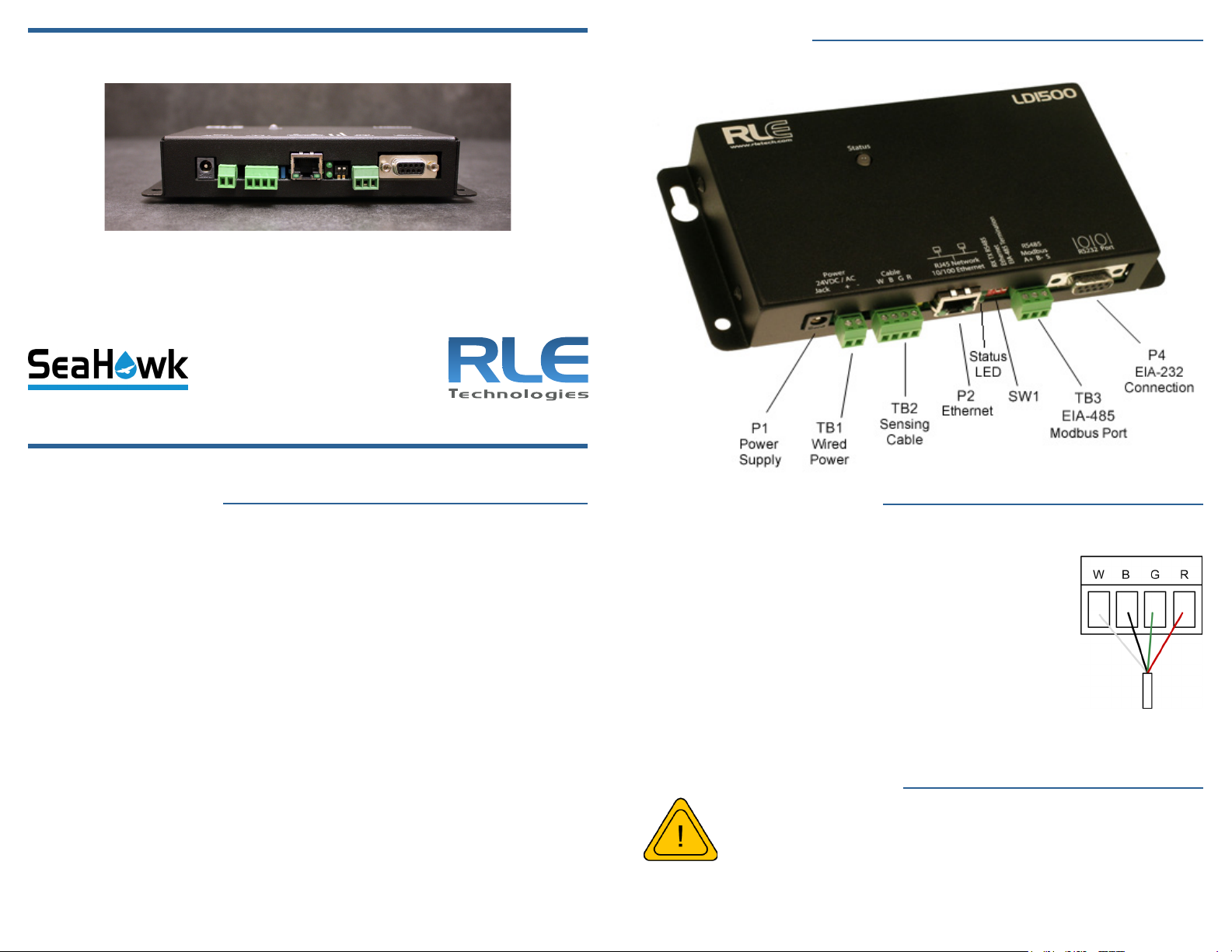
Install the Sensing Cable
Leader cable is included with the device and is used to connect sensing cable to
the LD1500, since sensing cable cannot connect directly to the controller.
1. Insert the four stripped wires of the leader cable into the
appropriate slots in the 4-pin terminal block connector from left to right: white, black, green, and red. Tighten
the screws on the terminal block connector to secure the
leader cable. Thread the leader cable through a knockout
on the bottom of the enclosure and plug the terminal
block connector into TB2.
2. Unscrew the EOL from the end of the leader cable.
3. Attach the rst length of sensing cable to the leader cable.
4. Route the sensing cable according to your cable layout diagram.
5. Secure the EOL to the unoccupied end of the sensing cable.
Apply Power to the LD1500
A dedicated circuit breaker must be provided within
close proximity to the LD1500 and be clearly marked as
the disconnecting device for the LD1500 leak detection
controller.
RLE recommends using a 24VDC wall adapter power supply (PSWA-DC-24-ST),
which is available separately from RLE.
1. Run a power supply to the location of the unit and plug it into P1. If you’re
Page 2
wiring power directly, insert the wires into TB1 as noted.
2. Apply power. The device will boot. No alarms should be present. If an
alarm is present, verify sensing cable is connected to the unit, and the endof-line terminator is connected to the end of the sensing cable. If the alarm
is still present, consult the LD1500 User Guide.
Set the LD1500’s IP Address
The LD1500 will not communicate properly over your network until you set the IP
address. Use the provided crossover cable and a computer to set the IP address.
(If you wish to congure the IP through the EIA-232 connection, consult the user guide
for alternative directions.)
1. Plug one end of the crossover cable into the ethernet port on the LD1500.
Plug the other end into your computer. This cable is NOT intended to plug
into a network hub, and won’t work if plugged into a network hub.
2. Write down the computer’s IP address, subnet mask, and default gateway.
Temporarily change the computer’s IP address to one that will allow it to
communicate with the LD1500 - the LD1500’s default IP is 10.0.0.188, so if
you set the computer to 10.0.0.190, they will be able to communicate.
3. Open the computer’s web browser and access the LD1500 - type it’s default
IP address - 10.0.0.188 - into the browser’s address bar and press enter.
4. You’ll be prompted to enter a user name - ld1500 (case sensitive) and a
password. By default, there is no password congured. Leave the password
eld blank and press the enter button.
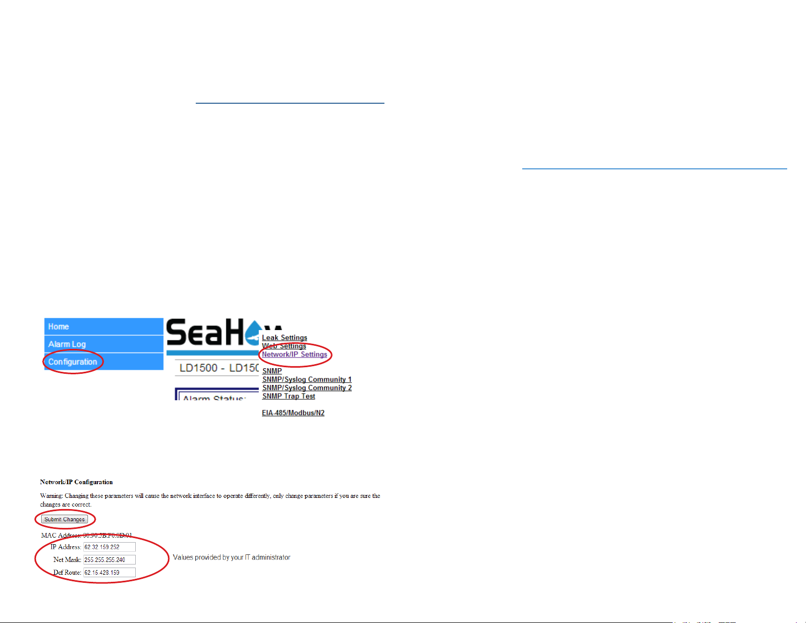
5. Click the Conguration link and then the Network/IP link.
8. The computer and LD1500 are now congured to communicate over
the network. Remove the crossover cable and properly connect the PC
and LD1500 to your network. Type the LD1500’s new IP address in the
computer’s browser and verify you can access the unit.
9. If the LD1500 is not accessible:
• Verify all cables are rmly connected to the correct ports.
• Verify that you entered the correct (new) IP address for the LD1500.
• Verify the LD1500’s status LED is green.
10. If the LD1500 is still not accessible, consult the LD1500 User Guide for
advanced conguration and troubleshooting information.
Test the System
If the LD1500 is already connected to a BMS or NMS, notify monitoring personnel
before you begin testing the system.
1. Using a sketch or mechanical drawing of the facility, add the cable routing,
connection points, and any accessories used. Record the distance marker
when the cable changes direction and in between connectors.
2. The more details you show, the greater the benet later when you are
locating leaks and troubleshooting the system
3. To verify the LD1500’s functionality, test three points within the length of
sensing cable - one at the beginning, one in the middle of the length, and
another near the end of the length of cable.
4. There are a variety of ways to simulate a leak.
• Pour a small puddle of water on the cable while it rests on the oor.
• Dunk the cable in a cup of water.
• Soak a paper towel or rag and wrap it loosely around the cable. This is
popular if the cable is used in pipe applications. Be careful to wrap the
wet cloth loosely around the cable. Do not put pressure on the cable.
6. Change the IP address, subnet mask, and default route to those provided by
your network administrator. Press the Submit Changes button. The LD1500
will save the new IP address and reboot.
7. Reset your computer to its original IP address and subnet mask.
IMPORTANT - To avoid inaccurate readings, do not grip the cable with your
hand.
5. Verify that the LD1500 reports the leaks within a few feet of their actual
physical location. If the leaks are reported in the approximate location, but
not precisely at the actual location of the leak, you may wish to calibrate the
system. Consult the LD1500 User Guide to calibrate the cable’s resistance,
which will provide the most accurate distance readings.
6. Remove all simulated leak sources and return the system to its normal
operating state.
7. To test the cable fault alarm, remove the end-of-line terminator (EOL) from
the end of the sensing cable. This will cause a cable break, which should
be reported appropriately by the LD1500. Once the cable break alarm
is veried, reapply the EOL and ensure the system returns to its normal
operating state.
 Loading...