

Page 1

RLE Technologies
Falcon Monitoring System
User Guide
Page 2

ii
Falcon User Guide
Page 3
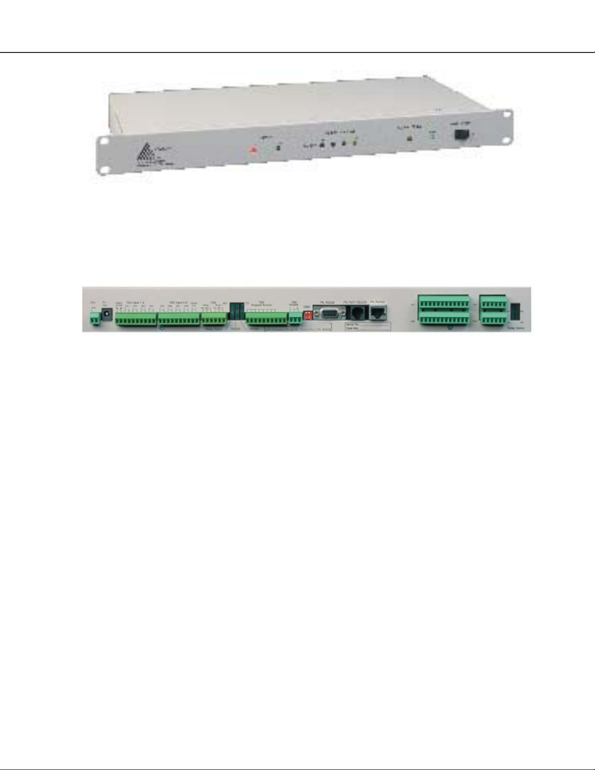
Falcon - Front View
iii
Falcon - Back View
All Falcon units are shipped from the manufacturer with a user guide.
24VDC models are also shipped with a wall adapter.
Falcon User Guide
Page 4

iv
Falcon User Guide
Page 5

v
Contents
Part One - Getting Started ..................................... 8
Chapter One - Product Description ................. 9
Product Description..................................... 9
Indicators and Controls - Front Panel .........10
Terminal Block Designation .......................11
Rear Panel Indicators ................................. 12
Detailed Switch Settings ............................ 12
Chapter Two - Falcon Installation.................. 13
Falcon Installation ..................................... 13
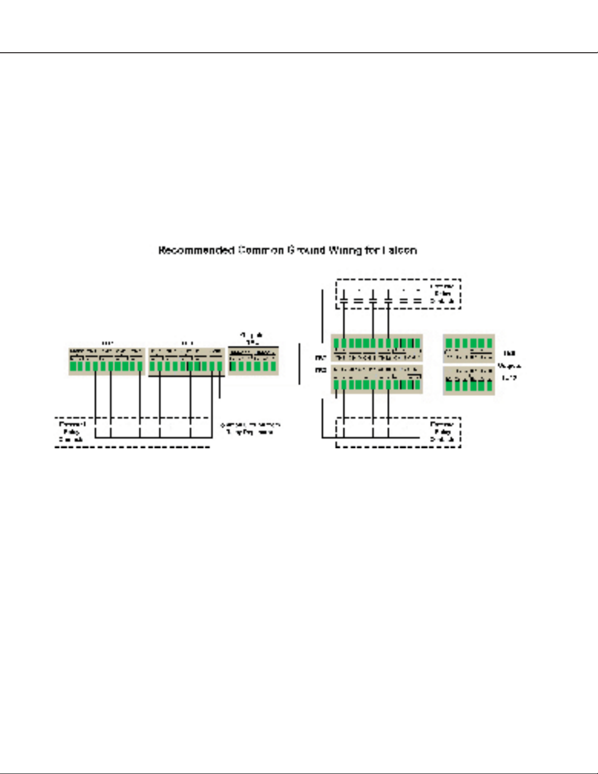
Common Ground Wiring...........................14
Sensor Wiring - Interface to Falcon ............15
Sensor Wiring - Transducer to Falcon.........16
Interface - Falcon Option Cards .................17
Part Two - Web Interface ......................................18
Chapter Three - RLE Falcon Main Menu.......19
RLE Falcon Main Menu.............................19
Access History ........................................... 20
Alarm History ........................................... 20
Event Log ...................................................21
Digital Status Log.......................................21
Log Menu...................................................21
Minute, Hour, and Day Links ................... 22
Identity...................................................... 22
Relay Status............................................... 22
WebCams.................................................. 23
Configuration ........................................... 23
Chapter Four - Configuration Menu ............. 24
Configuration Menu ................................. 24
Inputs........................................................ 24
Relays ........................................................ 26
System....................................................... 27
IP Configuration....................................... 29
WebCams.................................................. 29
Falcon Links.............................................. 30
Modem...................................................... 30
Configure Phone Numbers.........................31
Alarm Settings........................................... 32
Access Users .............................................. 32
Schedules................................................... 33
Battery....................................................... 33
EIA-485 .................................................... 34
Clock......................................................... 34
E-mail ........................................................35
Product Registration.................................. 36
Flash Program ........................................... 36
Part Three - EIA-232 Interface............................. 38
Chapter Five - Start-Up.................................. 39
Unit Start-Up............................................. 39
Flash Executable Code ............................... 40
Chapter Six - Main Menu ...............................41
Main Menu.................................................41
Chapter Seven - Log Menu ............................ 42
LM - Log Menu......................................... 42
1 - Alarm History Log ............................ 42
2 - Minute Log........................................ 43
3 - Hourly Log ........................................ 43
4 - Daily Log .......................................... 44
5 - Access Log ......................................... 44
6 - Event Log ...........................................45
7 - Log Information .................................45
8 - Digital Status Log.............................. 46
Mx, Hx, Dx, AHCHx............................. 46
RT - Run Times.......................................47
EH, ET, ER, EE, ED...............................47
20 - Return ............................................. 48
Chapter Eight - System Configuration........... 49
SC - System Configuration ........................ 49
1 - System Menu..................................... 49
1 - System Name.................................. 50
2 - Clock.............................................. 50
3 - Keypad Access .................................51
1 to 20 - Access Codes ......................52
21 - Exit Request Input .....................53
22 - Alarm Bypass Input .................. 54
23 - Alarm Dial Out .........................55
24 - Return ...................................... 56
4 - Inputs............................................. 57
5 - Relays ............................................. 59
6 - Input Power .................................... 59
7 - Analog Averaging ........................... 60
8 - Persistent Traps................................61
9 - Slave Inputs .................................... 62
10 - Slave Relays .................................. 63
11 - Schedules ...................................... 63
12 - BACNet........................................ 64
13 - Exit and Save ................................ 64
2 - IP Configuration Menu......................65
3 - Modem Configuration Menu .............67
Alarm ID Reference Tables............... 70
Falcon User Guide
Page 6

vi
4 - EIA-485 Configuration Menu ........... 72
5 - Factory Menu .....................................74
6 - Load/Save Config. Data Menu .......... 75
7 - Configuration Password .....................76
8 - E-mail, SMTP Menu......................... 77
x - Exit .................................................... 77
Part Four - Remote Access.................................... 78
Chapter Nine - Configure Remote Access...... 79
Part Five - PPP Access .......................................... 80
Chapter Ten - Configure PPP.........................81
Part Six - Firmware Uploads................................. 82
Chapter Eleven - Upload via TFTP Client..... 83
Chapter Twelve - Upload via EIA-232 Port .... 85
Appendices........................................................... 86
Appendix A - Option Card ............................ 87
Product Codes ........................................... 87
Installation ................................................ 87
Convert Input Channels ............................ 87
Appendix B - Technical Specifications ........... 89
Appendix C - Falcon 4-20mA Reference ....... 90
Falcon User Guide
Page 7

vii
Falcon User Guide
Page 8

8
Part One
Getting Started
Chapter One................. Product Description...................... 9
Chapter Two .................Installation..................................... 13
Falcon User Guide
Page 9

9
Chapter One
Product Description
The Falcon Monitoring System is a comprehensive
system which monitors critical operating parameters
in enterprises, remote network facilities,
communication rooms, remote and unmanned
facilities, and critical support systems. The Falcon
is a stand alone system. It operates via embedded
software that handles all data collection, alarm
reporting, and multiple concurrent communication
mediums:
• The EIA-485 port allows a user to
interconnect five units in a multi-drop
topology.
• The EIA-232 direct connection facilitates
firmware downloads, system configuration,
inquiries, and alarm reporting.
• The internal modem provides dial in/out
remote access support for the PC interface,
inquiry and alarm reporting, numeric and
alphanumeric paging, alarm
acknowledgement, PPP to ISP, e-mail over a
dial-up connection, and DTMF output relay
control.
• The Ethernet 10BaseT network port supports
SNMP V1 MIB for persistent alarm traps,
e-mail alarm delivery, information inquiry,
I/O configuration and modification, and
alarm acknowledgement. This port also
supports a UDP command set for third-party
access and development.
• BACNet allows the Falcon to communicate
with building management systems.
• The built-in Web Server enables the Falcon’s
web interface. This allows the Falcon to be
configured and its status to be checked from
remote locations.
10BaseT network port, status LEDs, and an interface
for one option card. The power source for the
standard unit is a 24VDC wall adapter. An optional
48VDC unit (FMS8-48) is available. Option cards
provide additional digital and analog inputs, up to
32 per unit. Reference Appendix A for option card
configurations.
The Falcon performs internal diagnostics that
check the flash program code, serial ports, RAM,
non-volatile RAM, real-time clock, internal power
supplies, relay drivers, analog to digital converter
(ADC), and modem. During operation, the Falcon
monitors its status and uses several LED indicators
to report its condition. The functions of these LEDs
are described later in this manual.
The embedded Falcon software enables system
configuration, I/O setup, status inquiries, alarm
reports, data logs, and troubleshooting. Falcon
software is menu driven and operates with any
ASCII terminal or terminal emulation application
such as HyperTerminal.
The universal inputs can be configured for digital
signals - Normally Open (NO) or Normally Closed
(NC) dry contacts - or analog signals (4-20mA).
The system will report any change of state or
values above or below specific set points. Data is
logged for all analog points. The high, low, and
average readings for each analog point are captured
in minute, hour, and day logs. Alarms for all
configured points are recorded in the alarm history
log. All logs are fixed field delimited for easy data
extraction and upload to other programs. Output
relays can be activated through manual intervention
or triggered by any input. Appropriate time delays
can be set for each relay. The Falcon can provide
24VDC power for external sensors.
The standard Falcon (FMS8) is configured in a rack
mount enclosure with eight universal inputs, two
digital output relays, a keypad interface, a power
source for external sensors, one EIA-485 port, one
EIA-232 port, one internal modem, one Ethernet
The Falcon supports a 3x4 numeric keypad interface
for controlled access to critical areas. Twenty access
codes and descriptions can be entered through the
configuration port or over the network via the web
browser interface. Access is granted when the system
validates a keypad entry. The system generates an
Falcon User Guide
Page 10
10
alarm after three invalid entries. Access codes can
also be entered via telephone using DTMF signaling
– just dial the unit and enter the access code
followed by the
an output relay for a user-defined period of time,
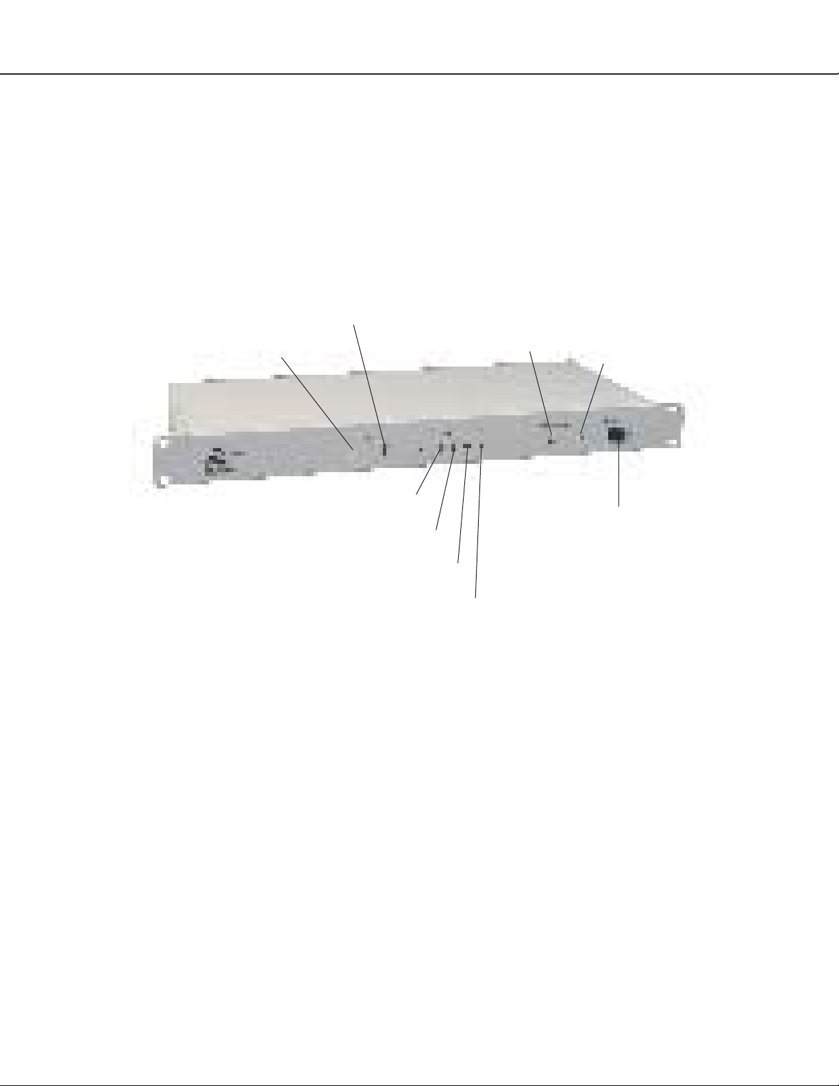
Falcon - Front Panel Indicators and Controls
# key. A valid entry activates
Network LED - Active
Network LED - Link
Communications LED - TX
Communications LED - RX
which in turn activates an equipment door latch or
electrical lock on an entrance door. An alarm bypass
feature is also provided for doors equipped with a
forced entry alarming contact.
System Status LED
System Power Switch
Power LED
Communications LED - OH
Communications LED - CD
Network LEDs – Two network status LEDs:
• Link - Green if network link is established, red if not.
• Active - On (green) when the link is transmitting or receiving data.
Communications LEDs – Four modem status LEDs:
• TX - On (green) – Information is being transmitted.
• RX - On (green) – Information is being received.
• OH - On (green) – Modem detects a dial tone (off hook).
• CD - On (yellow) – Carrier detected.
System Status LED – This LED illuminates (red) during initial boot of the system and flashes ten times per
second. If the initial boot fails, the LED continues to flash. This indicates a condition that requires service.
During normal operation, the system status LED turns solid red when the unit is in alarm condition.
Power LED – On (green) as long as power is on.
System Power Switch – Used to turn power to the unit on and off.
Falcon User Guide
Page 11

Falcon Terminal Block Designations
11
P1 TB2 TB3 TB4 TB5 TB6 SW2 P6
TB1
TB1-1 (+) Input for 24/48VDC power
TB1-2 (-) Input for 24/48VDC power
P1 24VDC wall adapter input (center +)
(not available with 48VDC version)
TB2-1 24VDC positive (+)
(power for sensors)
TB2-2 24VDC positive (+)
(power for sensors)
TB2-3 Channel 1 positive (+)
TB2-4 Channel 1 negative (-)
TB2-5 Channel 2 positive (+)
TB2-6 Channel 2 negative (-)
TB2-7 Channel 3 positive (+)
TB2-8 Channel 3 negative (-)
TB2-9 Channel 4 positive (+)
TB2-10 Channel 4 negative (-)
TB3-1 Channel 5 positive (+)
TB3-2 Channel 5 negative (-)
TB3-3 Channel 6 positive (+)
TB3-4 Channel 6 negative (-)
TB3-5 Channel 7 positive (+)
TB3-6 Channel 7 negative (-)
TB3-7 Channel 8 positive (+)
TB3-8 Channel 8 negative (-)
TB3-9 24VDC ground (power for sensors)
TB3-10 24VDC ground (power for sensors)
Status
LEDs
P3
P4 Option Card
TB4-1 Relay 1 normally closed (NC)
TB4-2 Relay 1 normally open (NO)
TB4-3 Relay 1 common
TB4-4 Relay 2 normally closed (NC)
TB4-5 Relay 2 normally open (NO)
TB4-6 Relay 2 common
TB5-1 Keypad column 1
TB5-2 Keypad column 2
TB5-3 Keypad column 3
TB5-4 Keypad row 1
TB5-5 Keypad row 2
TB5-6 Keypad row 3
TB5-7 Keypad row 4
TB5-8 Unused
TB5-9 Input signal normally open (NO)
TB5-10 Input signal return
TB6-1 EIA-485 positive (+)
TB6-2 EIA-485 negative (-)
TB6-3 EIA-485 ground
SW2-1 Unit termination switch
SW2-2 Master/slave switch
P6 EIA-232 female DB9 pin connector
P3 RJ-11 telephone line connector
P4 Ethernet 10BaseT connector
Falcon User Guide
Page 12

12
Falcon Rear Panel Indicators - Relay and Communication Status LEDs
The rear panel of the Falcon houses a series of green LEDs. The chart tracks indicator status when the
corresponding green LED is illuminated:
EIA-232 TX
K1
K2
EIA-485 TX
EIA-485 RX
EIA-232 RX
Base System
Detailed Switch Settings
EIA-485
+-
Master Unit #1
K3
K4
TB6
Gnd
Option Card
SW2
12
Off
On
K5
K6
Status Indicator
K1 output relay Energized
K2 output relay Energized
EIA-232 TX interface Data is being transmitted
EIA-232 RX interface Data is being received
EIA-485 TX interface Data is being transmitted
EIA-485 RX interface Data is being received
K3 to K6 output relays Energized (option card)
Switch is on.
Switch is off.
Slave Unit #2
Slave Unit #3
Slave Unit #4
Slave Unit #5
+-
+-
+-
+-
Gnd
Gnd
Gnd
Gnd
12
Off
On
12
Off
On
12
Off
On
12
Off
On
SW2-1 Termination switch ON (down) for first and last unit wired in the series.
Termination switch OFF (up) for all units between the first and last units wired in the series.
SW2-2 Master/Slave switch OFF (up) for master unit and ON (down) for slave units.
Falcon User Guide
Page 13

13
Chapter Two
Installation
1. The Falcon comes in a 19” rack mount
enclosure. Install the Falcon in the rack.
Use the proper anchoring method to mount
the unit securely.
2. Supply either 24VDC or 48VDC to the
unit.
Units have different model numbers.
24VDC model: FMS8
48VDC model: FMS8-48
Verify the model number and power rating (on
back of unit) before applying power.
3. The Falcon will not communicate over a
user’s network the first time it is connected
to the network. The manufacturer programs
the Falcon with a default IP address:
10.0.0.186, subnet: 255.255.255.0.
This default address must be changed to an
IP address that corresponds with the user’s
network before the Falcon can communicate
over the network.
a. Plug the crossover network cable that
shipped with the Falcon unit into the
laptop or workstation that will be used
to configure the Falcon. This cable is
not intended to be connected to a network
hub.
b. Write down the computer’s IP address.
Then change the IP address of the
computer from its existing address to one
that will allow it to communicate with
the Falcon, such as 10.0.0.185. It may be
beneficial to set the IP address to one that
is one number different from the Falcon’s
IP address.
ii. On the Configuration tab of the
Network screen, double click the
TCP/IP Ethernet component.
iii. On the IP Address tab of the
TCP/IP Properties screen, specify the
appropriate
IP address. Click OK.
The computer’s IP address has been
changed.
c. Connect the other end of the network
cable to the Ethernet port on the back of
the Falcon.
d. Change the IP address of the Falcon to one
provided by the network administrator.
This allows the Falcon to communicate on
the network.
e. Change the IP address of the computer
back to its original IP address. If the
computer was configured as DHCP - the
network domain controller assigns it an IP
address, return it to this state.
.
f. The computer and the Falcon are now
both configured to communicate on the
network. Both should be accessible via the
network.
4. The Falcon can be configured through
the web interface or through the EIA-232
interface. To use the web interface, follow the
direction in Part Two of this guide. To use
the EIA-232 interface:
a. Connect the EIA-232 port on the Falcon
to a terminal or PC running terminal
emulation software (HyperTerminal) with
a 9-Pin Male-Female straight through
serial cable.
Win95/98/NT directions
i. Click on Start > Settings >
Control Panel > Network.
b. Set the appropriate COM port to
baud, NO parity, 8 data bits,
1 stop bit, (9600/N/8/1), and
no software or hardware flow
control.
Falcon User Guide
9600
Page 14
14
c. Once the terminal emulation software
starts, press
and select/execute commands from the
Main Menu. If the Main Menu does not
appear, check the communication settings
and make sure the unit is powered on.
Enter (↵) on the keyboard
5. Connect all other interfaces as required.
6. Proceed with further configuration and
testing of the unit.
Falcon User Guide
Page 15
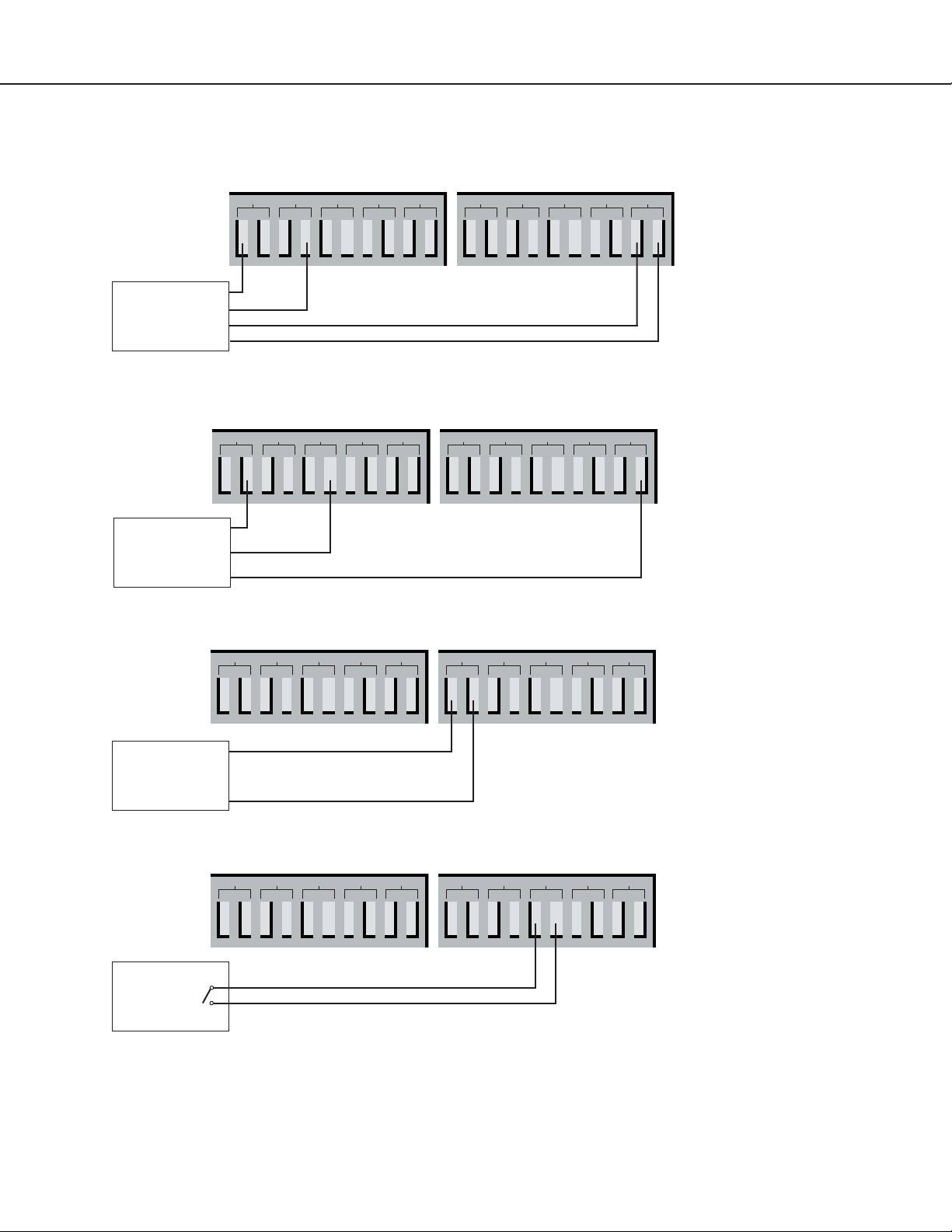
Examples: Sensor Wiring - Interface to Base Falcon
15
4 Wire
Analog
Sensor
3 Wire
Analog
Sensor
PWR
COM
PWR
OUT
GND
TB2 - Inputs 1 to 4
24VDC
Ch1 Ch2 Ch3 Ch4
+
+
- +
+
+
-
+
-
-
TB3 - Inputs 5 to 8
Ch5 Ch6 Ch7 Ch8 Gnd
+
-
+
-
TB2 - Inputs 1 to 4 TB3 - Inputs 5 to 8
24VDC
Ch1 Ch2 Ch3 Ch4
+
+
- +
+
+
-
+
-
Ch5 Ch6 Ch7 Ch8 Gnd
+
+
-
-
+
+
+
-
-
+
-
+
-
-
-
-
-
-
-
2 Wire
Analog
Sensor
2 Wire
Dry
Contact
TB2 - Inputs 1 to 4 TB3 - Inputs 5 to 8
24VDC
Ch1 Ch2 Ch3 Ch4
+
+
+
+
-
+
-
+
-
Ch5 Ch6 Ch7 Ch8 Gnd
+
+
-
-
+
-
TB2 - Inputs 1 to 4 TB3 - Inputs 5 to 8
24VDC
Ch1 Ch2 Ch3 Ch4
+
+
- +
+
+
-
+
-
Ch5 Ch6 Ch7 Ch8 Gnd
+
+
-
-
+
+
-
-
-
+
-
-
-
-
+
-
-
-
Falcon User Guide
Page 16
16
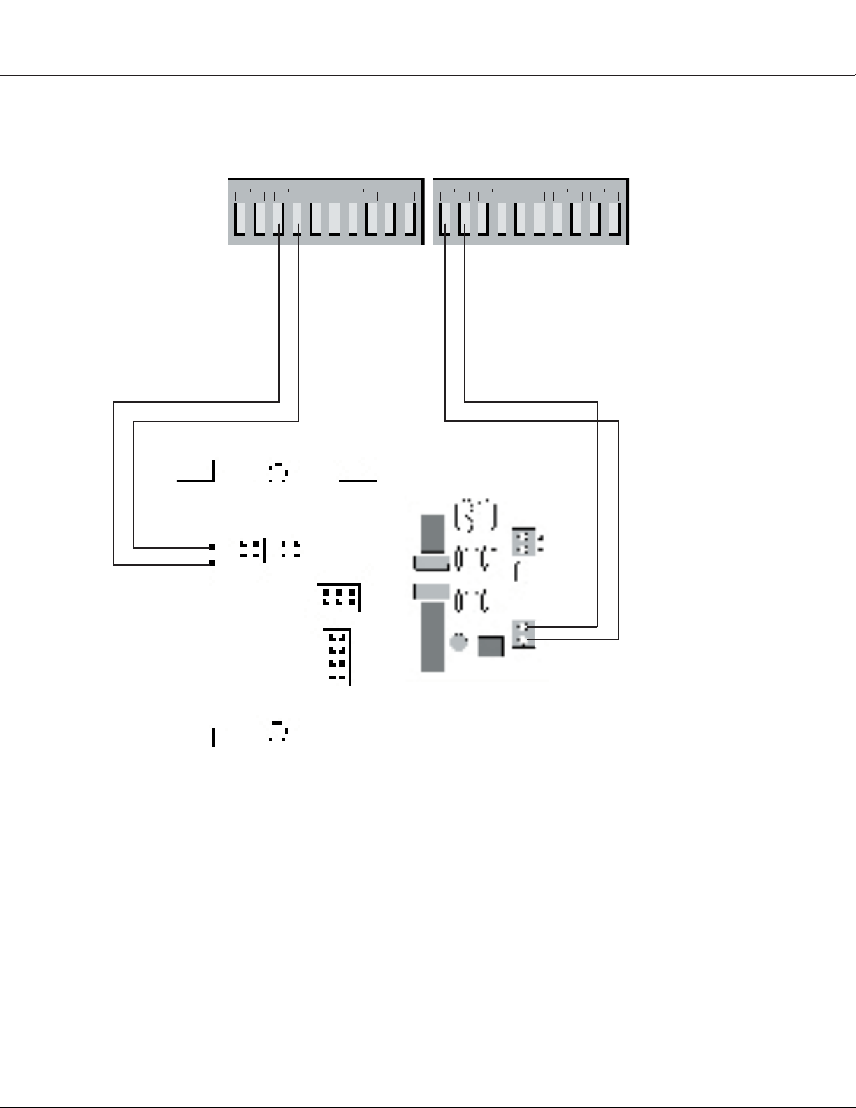
Sensor Wiring - RLE Transducer to Base Falcon
TB2 - Inputs 1 to 4 TB3 - Inputs 5 to 8
Falcon
24VDC
Ch1 Ch2 Ch3 Ch4
+
+
- +
+
+
-
+
-
Ch5 Ch6 Ch7 Ch8 Gnd
+
+
-
-
+
-
+
-
-
-
-
Humidity: Ch1 (-)
Humidity: Ch1 (+)
Tra nsducer
Two wire analog sensor with two channels
Temperature: Ch5 (+)
Temperature: Ch5 (-)
Falcon User Guide
Page 17

Interface - Falcon Option Cards
17
TB7
TB8
TB7
TB8
+
Ch09
Ch15
+
12 Input Digital Option Card -
Digital Inputs
+-
+-
+
-
+
Ch09
Ch15
+
-
Ch12
Ch11
Ch10
Ch16
Ch17
+
-
-
Ch18
+
+
-
+-
Ch13
Ch19
+
-
-
+-
Ch14
Ch20
+
-
12 Input Option Card -
Output Relays
TB9
NCNOC
RELAY 3
RELAY 5
NC NO C
NCNOC
RELAY 4
RELAY 6
NC NO C
TB10
24 Input Digital Option Card - Digital Inputs
-
-
Ch10
Ch16
+
-
+
+
Ch12
Ch11
Ch17
Ch18
+
-
+
-
+
+
Ch13
Ch19
+
-
-
-
+
Ch14
Ch20
+
-
-
+-
Ch21
Ch27
+
-
+
Ch22
Ch28
+
-
-
+
Ch23
Ch29
+
-
Ch24
Ch30
+
-
+
+
Ch25
Ch26
Ch32
Ch31
+
+
-
-
-
-
-
-
+-
TB9
-
TB10
Recommended wiring - RLE Technologies recommends 18 to 20AWG stranded copper for connection from
each monitored point to a terminal block (TB) connection on the Falcon. RLE recommends no more than 500
feet at this specification. If longer runs are needed, please contact RLE Technologies for application guidance.
Shielded twisted pair is recommended for analog signal transmitters being wired outside of conduit runs and
dropped ceiling applications.
Falcon User Guide
Page 18

18
Part Two
Web Interface
Chapter Three..............Main Menu .................................... 19
Chapter Four ................Confi guration Menu .................. 24
Falcon User Guide
Page 19
Chapter Three
Main Menu
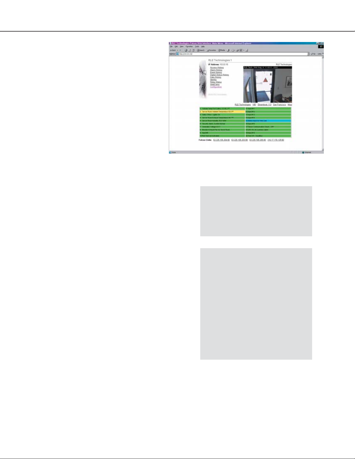
The Falcon’s web interface main menu provides
a convenient way to check the Falcon’s status
and reconfigure basic settings from any
Internet-enabled computer. A click of the
mouse allows users with proper permissions to
view the monitoring system’s output and alter
specific Falcon configuration settings.
The Falcon is shipped to the user with the IP
address configured as 10.0.0.186 and a subnet of
255.255.255.0. The user name is preconfigured
as Falcon. The unit is configured without a
password; when a password is requested, just leave
the space blank. These preconfigurations can be
changed to a personalized IP address, user name,
and password. Do this through the System link on
the Configuration Menu of the web interface.
To access the Falcon web interface, simply type the
IP address of the Falcon into the location bar of the
web browser. Then enter a user name and password.
19
Initial Falcon IP Address
Configuration:
Refer to chapter two to learn how to
change the Falcon’s factory assigned IP
address to one that will enable it to work
within a user’s network.
The bottom of the Falcon web interface features
two columns that list the Falcon’s configured inputs.
The number of inputs displayed corresponds with
the number of inputs on the Falcon. Each input
is numbered. The input’s name is followed by its
status.
The space behind each input is shaded. This
shading changes as the input’s status changes. This
allows users to tell, at a glance, the status of their
points. Shading is as follows:
Green: Input is normal - not in an alarm state.
Yellow: Analog inputs only - input is in high
alarm 1 or low alarm 1 state.
Red: Analog input - input is in high alarm 2
or low alarm 2 state.
Digital input - input is in an alarm
state.
Blue: Alarm/Input disabled by a schedule.
Optimize Use of Falcon Web Interface
Netscape’s “Smart Browsing” feature
complicates use of the Falcon Web
Interface. Turn off Smart Browsing to
avoid these complications:
• In the menu bar at the top of the
Netscape browser, click on Edit,
then on Preferences.
• Smart Browsing is a subcategory
of the Navigator category. Access
Smart Browsing and click the box
in front of the “Enable ‘What’s
Related’” option. Eliminate the
check mark to disable this option.
Falcon User Guide
Page 20
20
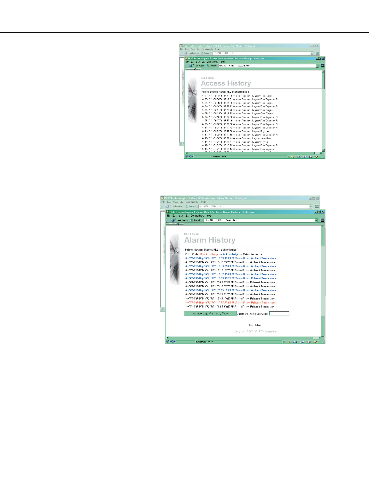
Access History
The
Access History link displays the last 100
entries captured by the master unit. The following
information is displayed: access log index (ALxxx),
date and time of event, whether access was granted
or denied, method of entry (keypad or DTFM), and
the description associated with the access code.
Alarm History
The Alarm History link displays the last 100
alarms captured by the master unit.
The following format is used to record
each alarm entry:
AH###-ID-Condition-Date Time
(Value UOM) Label
AH### is the alarm entry index.
ID is the alarm identifier number.
See Alarm ID Reference Table
Condition is On, High1, High2,
Low1, Low2, or RTN
– Returned To Normal.
Date and Time is the internal date
and time stamp of the alarm
condition.
Label is the alarm descriptor – can be
up to 64 characters long.
Value and Unit of Measure (UOM)
are captured for analog channels only.
The value recorded is the actual analog
value that exceeded its alarm threshold.
Alarms can also be acknowledged from this page.
To do so, type the appropriate code in the box at
the bottom of the page and click the
Alarms by Code button.
Acknowledge
Falcon User Guide
Page 21
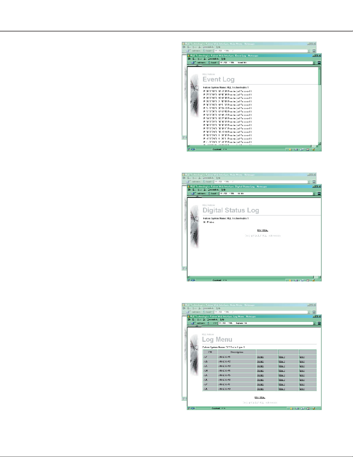
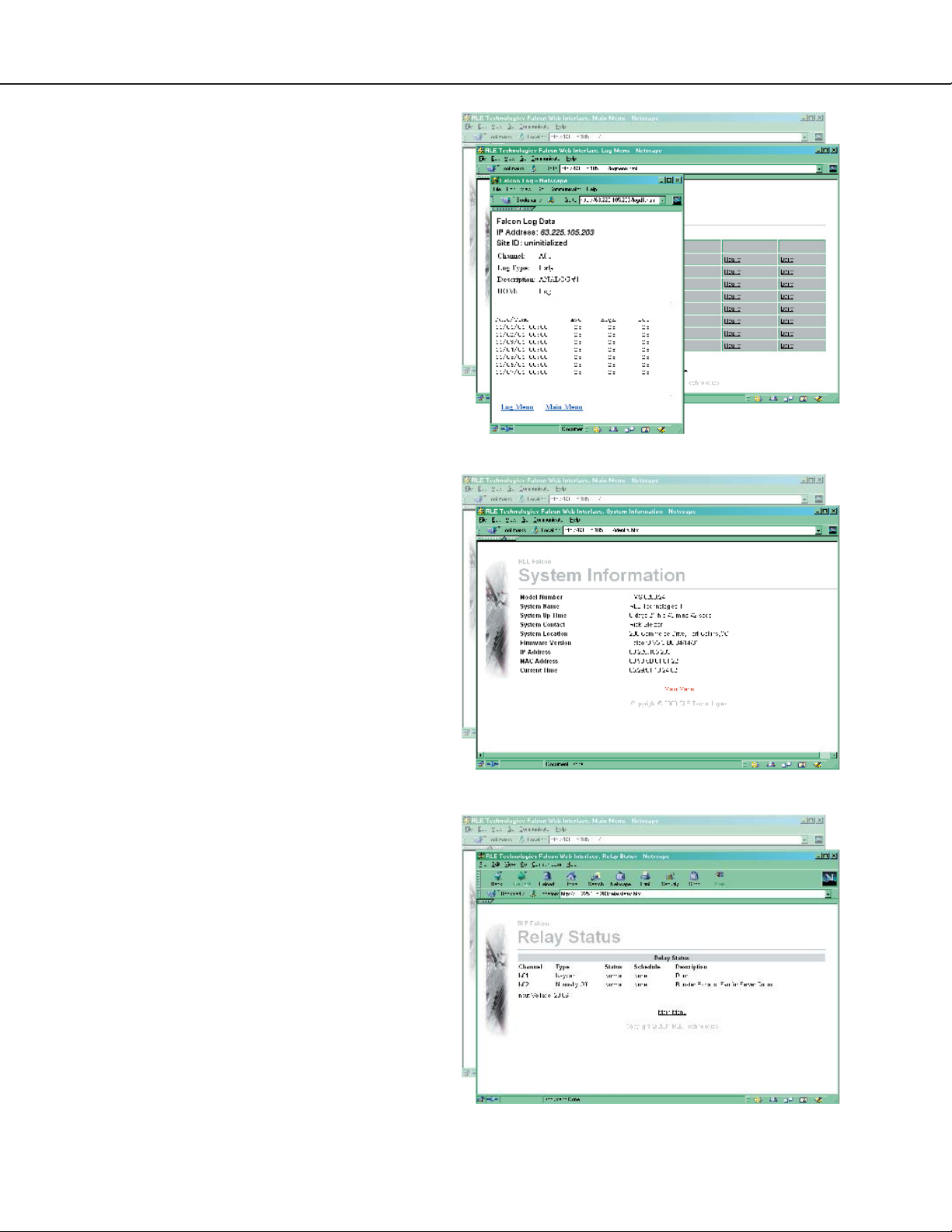
Event Log
The
Event Log link displays the past 100 events, as
recorded by the Falcon.
Digital Status Log
A digital input can be configured as NO, NC, or
status. If the digital input is configured as status, it
will not alarm, but it will appear on this page. The
Digital Status Log link displays a history of
the state of digital points configured as status points.
21
Log Menu
The
Log Menu link displays links to the Falcon’s
data logs.
Falcon User Guide
Page 22
22
Minute, Hourly, and Daily Links
The
Minute, Hourly, and Daily links on the
Log Menu screen display the detailed information
the Falcon records in its logs.
Identity
The
Identity link displays basic Falcon
information, including model number, firmware
version, and IP address.
Relay Status
The
Relay Status link displays the status of each
Falcon relay output.
Falcon User Guide
Page 23
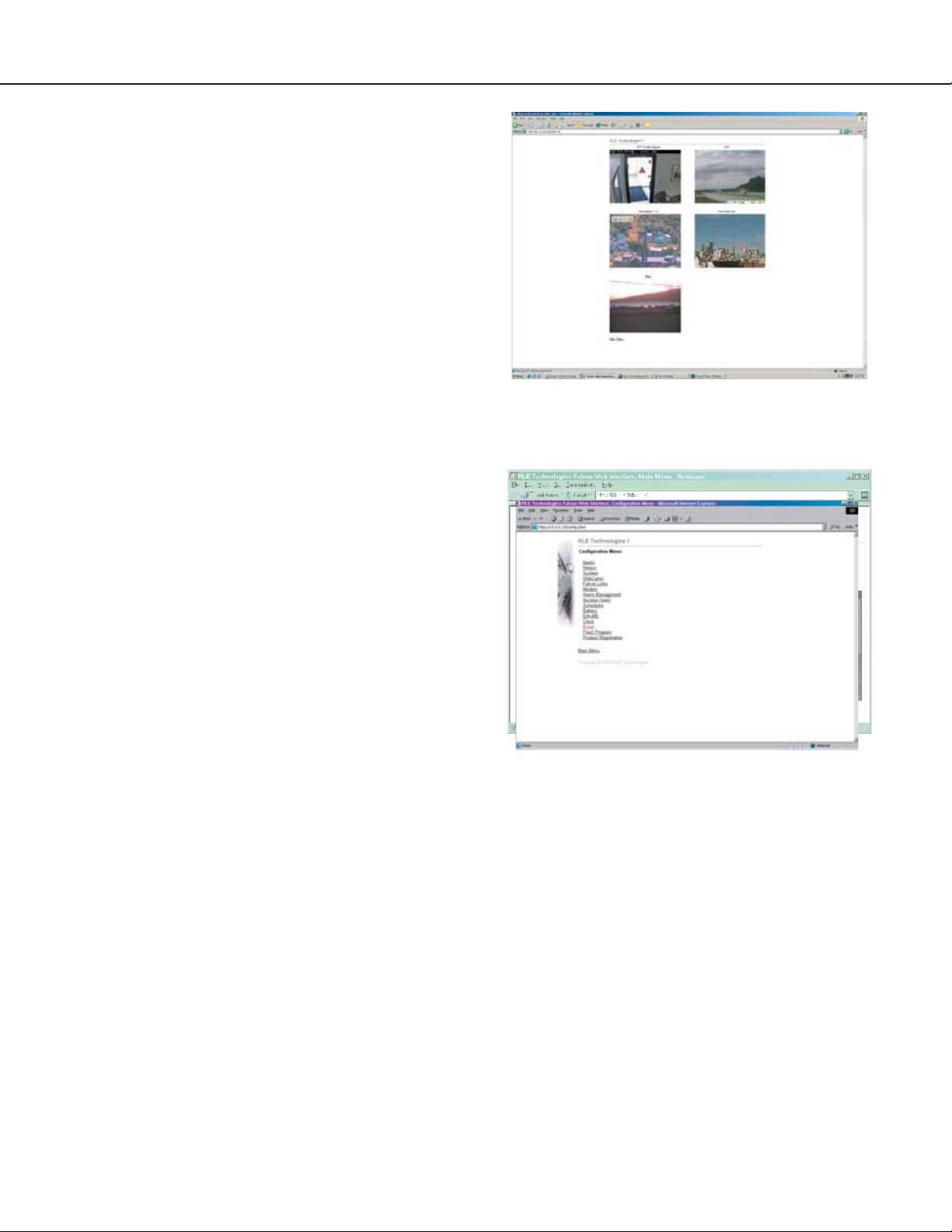
RLE Falcon WebCams
The WebCam link displays a still image (jpg) of all
web cameras linked to the Falcon.
RLE Falcon Configuration
The Confi guration link displays a menu that
allows authorized users to configure the Falcon’s
settings. The Configuration Menu is described in
greater detail in the next chapter.
23
Falcon User Guide
Page 24
24
Chapter Four
Configuration Menu
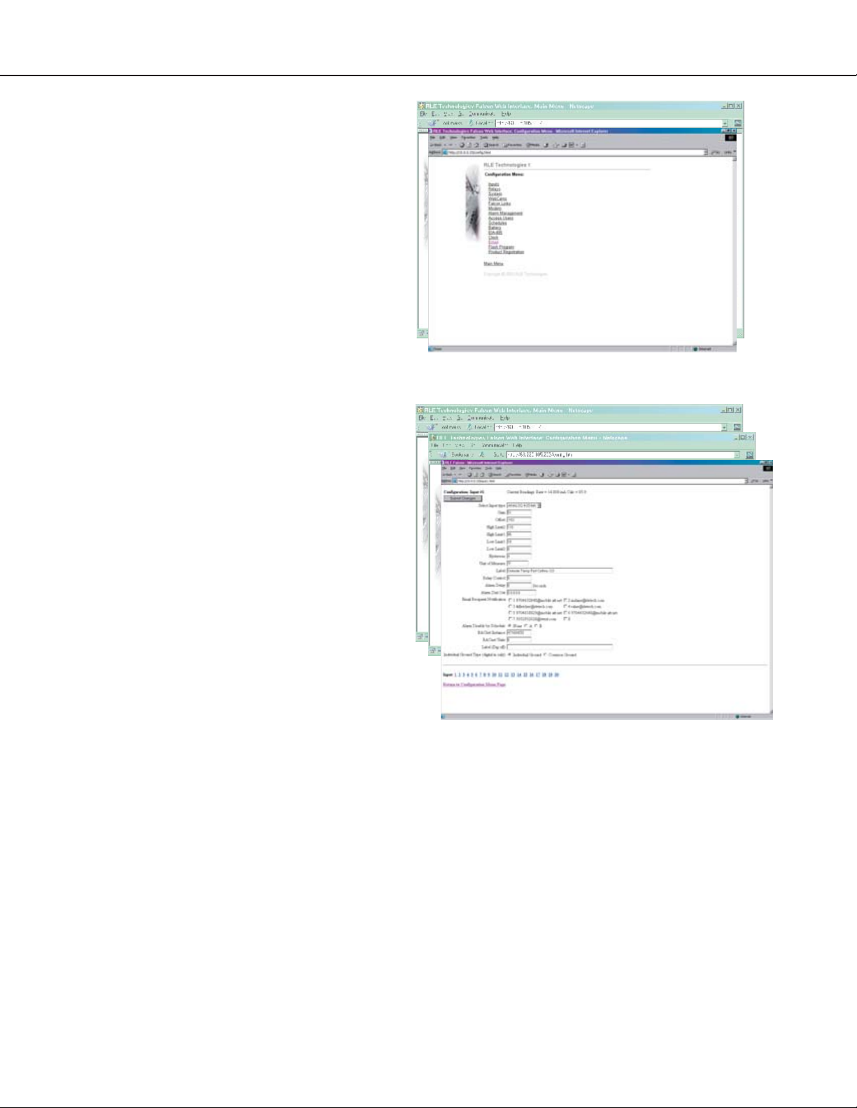
RLE Falcon Configuration Menu
The Configuration Menu allows authorized users to
adjust the Falcon’s settings. Each link displays a
page with specific configuration settings.
Inputs
The Inputs link allows users to program specific
parameters for each Falcon input. Users must push
the
Submit Changes button after they configure
each input. If the changes are not submitted before
proceeding to the next input, all changes will be lost.
The number of inputs varies with installed option
cards.
Per channel, select the appropriate number to modify
inputs and either pick an item from a menu or type
the value or description for the item selected.
Gain and Offset
Gain for 4-20mA Transducer = (Sensor High
Range – Sensor Low Range)/4
Offset for 4-20mA Transducer = Sensor Low
Range – Gain
Relay Control
The table on the next page represents control values
for the Output Control Standard Relays (K1 and
K2) and Optional Relays (K3, K4, K5 and K6).
Select the appropriate value of the relay to activate it,
or add the respective values of the appropriate alarm
condition to activate more than one output relay.
Each input can have individual control values.
Falcon User Guide
Page 25

25
Examples:
Relay Control: 2 Depending on channel
configuration, this setting will
activate Output Relay K2 for
either an analog 2nd Stage
High Alarm or a dry contact
change-of-state.
Relay Control: 64 Setting will activate Output
Relay K3 for an analog 2nd
Stage Low Alarm.
Relay Control: 35 Depending on channel
configuration, this setting will
activate Output Relays K1,
K2, and K4 for either an
analog 2nd Stage High Alarm
or a dry contact change-ofstate (1+2+32).
Relay Control: 10 Setting will activate Output
Relay K2 for either an analog
2nd Stage High or 2nd Stage
Low Alarm (8+2).
Relay Control: 76 Setting will activate Output
Relays K1, K2, and K3 for an
analog 2nd Stage Low Alarm
(4+8+64).
Unit of Measure is the appropriate unit of
measure for that input.
Relay Alarm Condition Value
K1 High2 Analog Alarm 1
K1 Low2 Analog Alarm 4
K1 Digital Alarm 1
K2 High2 Analog Alarm 2
K2 Low2 Analog Alarm 8
K2 Digital Alarm 2
K3 High2 Analog Alarm 16
K3 Low2 Analog Alarm 64
K3 Digital Alarm 16
K4 High2 Analog Alarm 32
K4 Low2 Analog Alarm 128
K4 Digital Alarm 32
K5 High2 Analog Alarm 256
K5 Low2 Analog Alarm 1024
K5 Digital Alarm 256
K6 High2 Analog Alarm 512
K6 Low2 Analog Alarm 2048
K6 Digital Alarm 512
sensor must register 76°F before the Falcon reports it
as returned to normal.
Alarm Dial Out is the order in which the Falcon
sends alarm notification. The numbers correspond
to phone numbers configured from the
Phone Number links at the bottom of the Modem
Configuration page.
BACnet Instance is a BACnet object identifier.
Config
It is a numerical code used to identify the input.
This code must be unique within the BACnet
device. Refer to the BACnet standard for further
information.
Label is the appropriate label for the particular
input.
Alarm Delay is the amount of time the Falcon
waits to send an alert after an alarm condition is
detected.
Hysteresis is a number that designates the
amount an input reading must sway from its preset
alarm reading before it is classified as returned to
normal. For example, a temperature sensor alarms
when it reaches 80°F. If hysteresis is set at four, the
BACnet Unit is the BACnet engineering units.
This represents the units of measurement for the
input. Refer to the BACnet standard for further
information.
Label (Dig off) is the label that is associated
with a digital input when it is in an off state. When
the digital input is in the on state, this label is used.
Falcon User Guide
Page 26
26
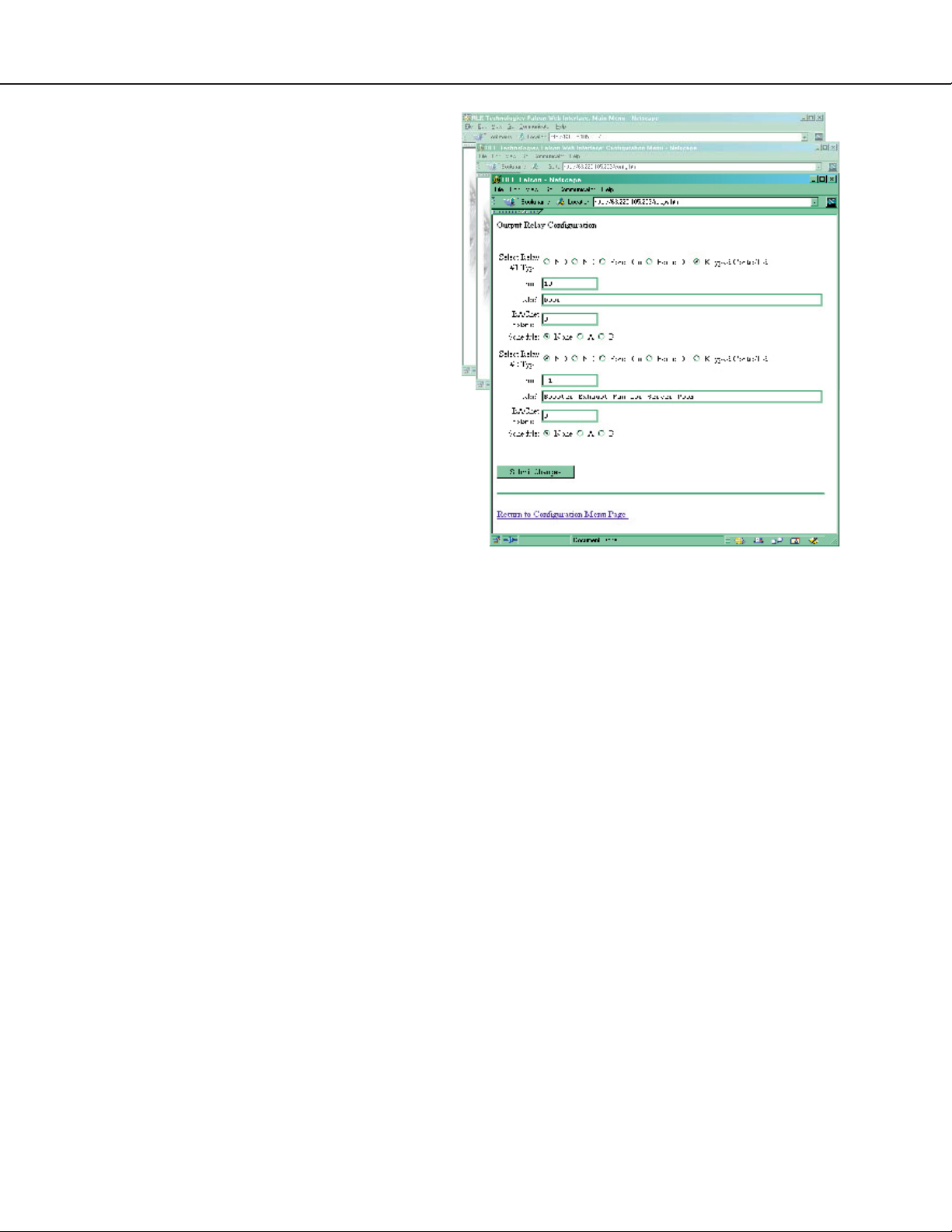
Relays
The Relays link displays a screen that configures
the Falcon’s output relays.
Select a type for each relay. The
time field then
designates the number of seconds the relay is active:
timed control 30=30 seconds,
-1 = continuous,
following the alarm input.
Label is the appropriate label for the particular
relay.
BACnet Instance is a BACnet object identifier.
It is a numerical code used to identify the input.
This code must be unique within the BACnet
device. Refer to the BACnet standard for further
information.
BACnet Unit is the BACnet engineering units.
This represents the units of measurement for the
input. Refer to the BACnet standard for further
information.
Schedule designates which of the schedules from
the
Schedule Configuration menu the relay
will adhere to.
Again, the
Submit Changes button must be
pressed once changes are complete, or all changes
will be lost.
Falcon User Guide
Page 27
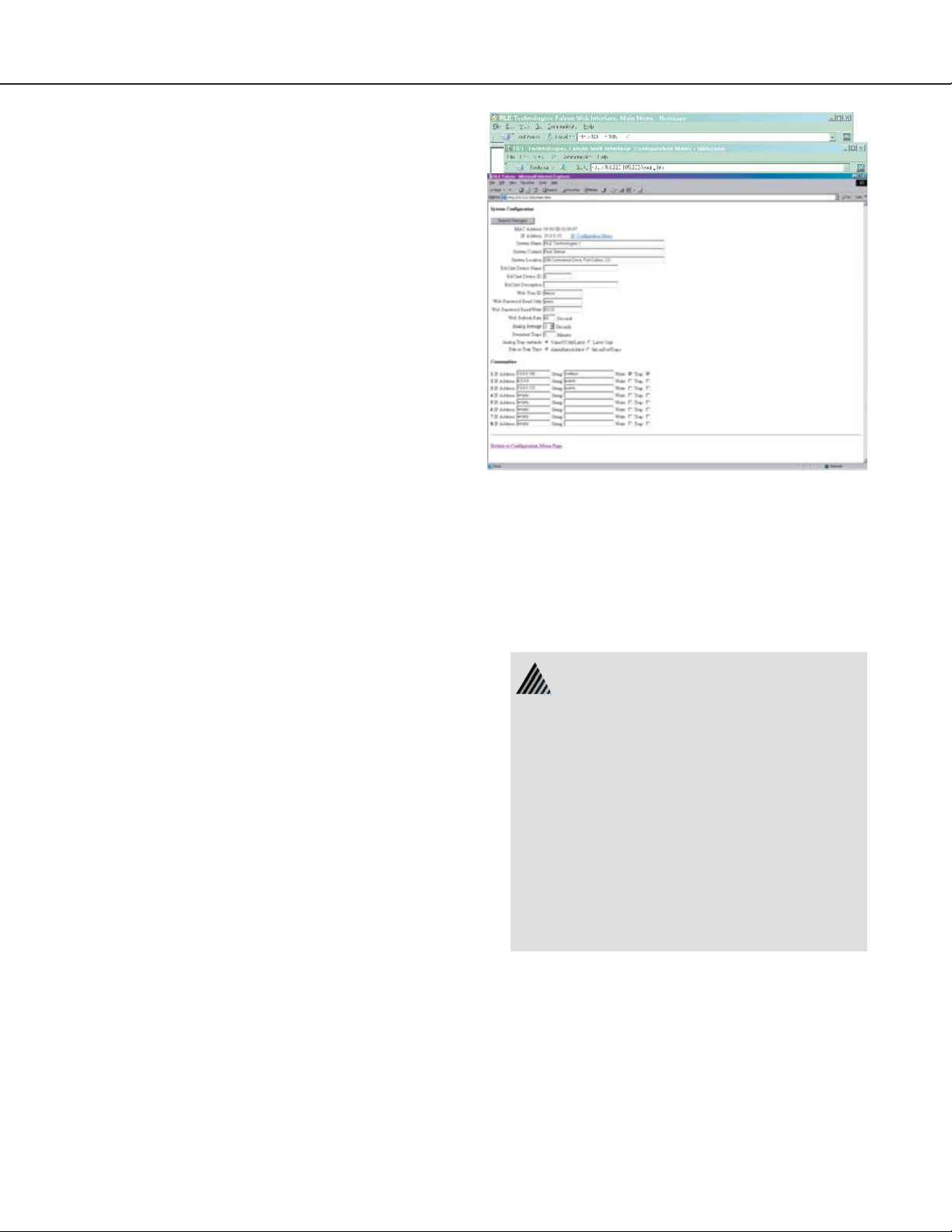
System
The System link allows users to configure basic
Falcon information. The Falcon’s IP address may
also be changed from this page.
System Name is the name of the Falcon.
System Contact is a contact person for the Falcon
unit.
System Location is the physical location of the
Falcon.
BACnet Device Name is similar to the
System Name but is bound by some BACnet
standards. Refer to the BACnet standard for further
information.
BACnet Device ID is similar to the BACnet
Instance
but it applies to the entire device. Refer
to the BACnet standard for further information.
27
BACnet Description is similar to the system
description, but has some limitations. Refer to the
BACnet standard for further information.
Web User Id is falcon (default). This Id can be
changed allowing up to 18 characters.
Web Password Read Only allows users to access
the Falcon web interface.
Web Password Read/Write allows users
to access the Falcon web interface and web
configuration screens.
Web Refresh Rate is the rate at which the
Falcon’s web pages refresh themselves within the web
browser.
Analog Average allows the user to change the
averaging method for analog inputs. Normally,
the system samples analog points once a second
while keeping track of high and low values for each
analog point. After sixty seconds, the average of
these readings and the high and low values for these
To enable the SNMP receiving stations,
the Falcon MIB, provided on a diskette
with every unit, must be loaded on a
system(s) running a Network Operating
System (NOS). This MIB is compiled
through standard functions of the NOS.
Consult with the Network Administrator for
proper installation of the Falcon MIB on the
NOS. Once the MIB is loaded, the Falcon
unit(s) can be discovered and configured
over the network. For proper operation,
the IP addresses configured in the Falcon
communities must match the IP addresses
on the receiving stations.
Falcon User Guide
Page 28

28
points are recorded in the minute log. To alter this
method of averaging, change the value to one of the
values listed in the drop down menu. Zero or one
maintains the method described above; a higher
value changes the method of averaging and the
manner by which high and low values are recorded.
An example of how averaging is altered and how it
impacts high and low recordings is shown here.
• Analog averaging value is set to 5.
• The analog point is a temperature sensor.
• Temperature readings are displayed for an
eleven second period:
Under normal conditions, the average reading would
equal 71, the high value would equal 74, and the low
value would equal 70. By changing the averaging
70,70,70,71,71,72,72,73,73,74,74
Average = 70, High Value = 70, Low Value = 70
70,70,70,71,71,72,72,73,73,74,74
Average = 70, High Value = 70, Low Value = 70
preferred, the Falcon can send only the label on
Analog traps.
Falcon Trap Types is set by default to send an
alarm entry added type trap. The Trap type can be
set to a Port Type Trap.
Communities identify computers that receive
SNMP traps from the Falcon and interact with the
Falcon over the network. To add a computer to
the communities list, select a community number
posted as “empty.” Enter the receiving computer’s
IP address and a string that identifies
the computer. An IP address of 0.0.0.0 in the
Communities > IP Address field allows any
computer to access the Falcon through an MIB
browser or RLENet. Check the box next to write
if the machine will have read/write network access
- this allows the computer to be configured over
the network. Check the box next to traps if the
computer will receive traps.
70,70,70,71,71,72,72,73,73,74,74
Average = 71, High Value = 71, Low Value = 70
70,70,70,71,71,72,72,73,73,74,74
Average = 71, High Value = 71, Low Value = 70
70,70,70,71,71,72,72,73,73,74,74
Average = 72, High Value = 72, Low Value = 70
70,70,70,71,71,72,72,73,73,74,74
Average = 72, High Value = 72, Low Value = 70
70,70,70,71,71,72,72,73,73,74,74
Average = 73, High Value = 73, Low Value = 70
method, the average reading ends up at 73, the
high value at 73, and the low value for this example
remains the same. In a sense, averaging slows down
the sensor response and the rate of change. This
parameter impacts all analog points.
Persistent Traps enables the Falcon to issue
continuous SNMP alarm traps until an Alarm
Acknowledgement is received by the Falcon. The
parameter is a user-defined time interval that is set
in minutes.
Changes will not go into effect until the
Changes button is clicked.
Submit
Analog Trap Varbinds is for communication
to a NMS via the SNMP traps. The default will
add the value/UOM (unit of measure)/label. If
Falcon User Guide
Page 29

IP Configuration
The IP Confi guration link allows users to
change the Falcon’s IP address.
Contact a network administrator to obtain a valid IP
address for the network. Then, type the appropriate
IP address, net mask (subnet), and default route into
the interface.
HTTP Port
The Falcon broadcasts its web pages on port: 80 of
the IP address assigned. A zero in the field block
defaults the Falcon to Port: 80. This can be changed
to a specific port allowing increased security of the
web page broadcast.
TCP Max Segment Size 1436 or 536
The Falcon is defaulted to send web pages at a 1436
TCP seg. size. A smaller TCP seg. size helps with a
conjested network.
29
Refer to Part Five of this User Guide to learn more
about PPP and establishing a PPP connection with
the Falcon.
Changes will not go into effect until the
Changes button is clicked.
Submit
WebC a ms
The WebCam Confi guration link allows up to
five IP addressable web cameras to be linked to the
Falcon.
The first field, Web Cam #x JPG URL will display a
still image (jpg) on the main page of the Falcon.
The second field, Web Cam #x Home URL will
open a second window and give the PC a direct link
to the WebCam allowing streaming video to be
displays.
The third field, Web Cam #x Link Test will display
the name assigned to the image..
Falcon User Guide
Page 30

30
Falcon Links
The Falcon Links link allows up to four
Falcons or IP addressable devices to link to the
Falcon.
Modem
The Modem link allows users to configure the
Falcon’s internal modem. The initialization string
can be a maximum of 38 characters.
are mandatory.
s0=1 sets the modem to answer
after one ring.
The dial prefix should be a specific Hayes
compatible command or dial modifier. It is also
limited to 38 characters. The default is set to
Pager Deliveries designates the number
of times to call the pager until the alarm is
acknowledged - 1 to 255. Pagers are called in
sequence. For example, if
Pager Deliveries is
set to 3 and pagers 1, 7, and 10 are programmed to
be notified, the Falcon dials 1, 7, 10, 1, 7, 10, 1,
7, 10. As soon as the alarm is acknowledged, the
Falcon quits dialing the pagers with that particular
access code. Pagers with different access codes are
still dialed.
&c1 and &d3
atdt.
Pager Interval allots the number of minutes to
wait between redials.
Pager No Ack Alarm establishes a number to
call if the alarm isn’t acknowledged. A numbered
contact (one through 16) designates the number to
call.
Pager Baud Rate designates the pager baud rate.
Pager Unsuccessful Traps will allow the
Falcon to send an SNMP trap to the NMS if set to
YES.
Pager Resend will send all unacknowledged
alarms in the Alarm History menu if set to
YES.
It will only send the last unacknowledged alarm if
set at
NO.
Modem Password defines a remote access
password, seven characters max.
Redial Attempts sets a number of times to call a
number until the call is successful, from one to 255.
Redial Interval establishes the number of
minutes to wait between redials, from one to 255.
Comm Check Phone defines a numbered contact
(one through 16) to call to check communications.
Comm Check Time sets a time (24 hour format) to
make the communications check.
Force Alarm Acknowledge Code acknowledges
all unacknowledged alarms. This acts as a master
code and can override all other alarm acknowledge
codes.
Changes will not go into effect until the
Changes button is clicked.
Submit
Falcon User Guide
Page 31

Configure Phone Numbers
This page is accessed through the
Number link at the bottom of the Modem
Config Phone
Configuration page. This screen allows users to
configure pager and cell phone numbers that are
used for alarm notification.
A drop down menu allows the user to select
which type of device the Falcon calls. Use the
text option to dial a PC receiving ASCII strings.
Alpha-numeric Pager dials an alphanumeric
pager.
FalconView dials a PC running FalconView
Numeric Pager dials a numeric pager.
software.
Number blank is filled in with the pager service
The
number for numeric and alphanumeric pager entries.
Each comma after the pager number represents a two
second delay. This delay is used to allow enough
time for the pager service to answer before requesting
the pager ID. Experimentation with the proper
number of commas may be necessary.
The
Pager ID field is mandatory for numeric and
alphanumeric pagers.
Alphanumeric pager - This ID is sent to the
paging service along with all queued alarm
messages. The ID is the unique PIN for a
specific pager. The ID may be a maximum of
16 characters.
Numeric pager - The ID may be configured to
deliver different numeric messages. The ID can
contain 15 characters: any combination of the
numerals 0 through 9 and a
* or #. These are
the only characters that will be transmitted to
the paging service.
Each paging service interprets * and #
differently. Before using these characters,
consult the paging service to see how they are
interpreted and when they should be used.
An effective numeric page depends largely on
the parameters established by the paging service.
Experimentation may be required to achieve desired
results.
The
Acknowledgement Code is any number, up
to six digits, used to acknowledge receipt of an alarm
and to terminate any additional call outs for this
phone number.
Dial Back on Returns designates whether
to call this number again once the alarm condition
returns to normal.
31
A
$ can be added or inserted anywhere into the
message string. This is converted into a 5 digit
alarm code:
X - binary alarm condition: 1=on, 0=return to
XYZZZ.
normal (RTN)
Y - multi-drop address of the Falcon (0-4)
ZZZ - alarm ID number - see reference table
Changes will not go into effect until the
Changes button is clicked.
Acknowledge an Alarm:
1. Dial Falcon from any phone.
2. Wait for the computer tone.
3. Enter
acknowledgement code
by the
# key
.
Falcon User Guide
Submit
followed
Page 32

32
Alarm Settings
The Alarm Settings link displays a menu that
allows users to acknowledge current Falcon alarms
and clear the Falcon’s alarm and access history. A
click of each of these buttons will complete the tasks.
Access Users
The Access Users link displays a screen that
allows configuration of a maximum of 20 access
codes and user names. The access code can be up
to six digits long and the user name up to twenty
characters long.
Exit Request and Alarm Bypass Inputs
may also be configured from this menu. Exit
request devices provide a dry contact interface which
signals a request-to-exit relay to unlock a door. The
alarm bypass input is used in conjunction with the
controlled access function of the Falcon. When
enabled, the alarm circuit on the door is bypassed
upon entry of this valid access code.
Press the
Submit Changes button after
configuration is complete or all access user
configuration changes will be lost.
Falcon User Guide
Page 33

Schedules
The
Schedules link allows users to schedule the
activation and deactivation of relay outputs. This
is useful for cycling redundant equipment such as
chillers, generators, etc.
33
Press the
Submit Changes button when done to
save all schedule changes.
Battery
The
Battery link is used to configure power when
the Falcon is running off a 48V battery string.
Press the
Submit Changes button when done to
save all battery configuration changes.
Falcon User Guide
Page 34

34
EIA-485
The
EIA-485 link is used to create polling addresses
for Falcon units wired in series on the EIA-485 bus,
as well as the communications baud rate for the bus.
Before entering addresses, be sure each unit’s SW2
is set properly. Each poll address must be a unique
number from 2 through 254. They are entered
sequentially, separated by commas.
9600 is the default baud rate setting.
Alarm Dial Out specifies which of the
pre-programmed phone numbers to dial if a
communications loss occurs, and in which sequence
to call them.
Press the
Submit Changes button when done to
save all schedule changes.
Clock
The
Clock link allows users to set the date and time
on the Falcon’s internal clock.
Press the
Submit Changes button when done to
save all schedule changes.
Falcon User Guide
Page 35

Email
Falcon firmware versions 5.3 and above can send email messages over a network connection or through
a dial-up connection to an ISP. The
Email link
allows users to configure the Falcon so it sends alarm
notifications via e-mail. The Falcon will send one
e-mail message per alarm instance to a maximum
of eight e-mail recipients. This allows the Falcon to
send e-mail messages when inputs are in alarm state.
The
Email link displays a data entry form which is
used to configure the e-mail settings.
Access Type specifies to send the message
•
through a local network or over a PPP dial up
connection.
35
• DUN User Name and Password are only
used if PPP is selected. Use these blanks to
specify the dial-up networking user name
and password. Contact your ISP for this
information.
•
DUN Phone Number is the number the
Falcon dials to connect to the ISP. Contact
your IT Department to obtain this phone
number.
•
DNS Servers are provided by your ISP. This
information is needed to deliver the e-mail
message.
• The
Mail (SMTP) Server specifies the
e-mail server used to receive/send mail.
• The
Mail Sender Address is the address
that will be displayed in the form field of the
e-mail messages.
• Up to eight e-mail recipients can be specified
in the
Mail Recipient (1) through
Mail Recipient (8) fields.
SMTP Authentication is used for ESMTP.
•
Do not change from the default setting unless
instructed by your IT Department.
When the information is complete, click
Changes for the changes to take effect.
Submit
An individual e-mail client can be configured to
enhance the capabilities of the Falcon. The e-mail
client can be set up to filter e-mails from specific
Falcons and automatically place the e-mails into
specific folders. Some e-mail clients can also be
set up to automatically forward the e-mail to other
recipients.
• The
Mail Subject is displayed in the
subject field of the received e-mails. Adding
&m inserts the MAC Address of the Falcon
into the e-mail subject line. This ensures the
e-mail subject is always unique to a Falcon.
Falcon User Guide
Page 36

36
Flash Program
The
Flash Program link specifies which versions
of Falcon firmware are loaded onto the Falcon. Only
two copies can be loaded onto the Falcon at a time.
In order to upload a program update, the backup
flash must be blank. If it is not, click the
Backup button to erase it. This erases the oldest
version of firmware stored on the Falcon. Using a
TFTP client software program, send the falcon(vx.x
bx).bin file to the IP address of the Falcon. The
Falcon verifies the file name starts with
ends with
.bin. Other file names or types will
not be accepted. The Falcon will accept TFTP block
sizes of 64, 128, 256, 512, or 1024.
Once the program has been successfully uploaded,
the Falcon will automatically reboot.
Erase
falcon and
Product Registration
The
Product Registration link allows the
Falcon to be registered on RLE’s database at the
time of configuration. IP address, subnet makst and
default gateway must already be set on the Falcon
before this link will work.
Falcon User Guide
Page 37

37
Falcon User Guide
Page 38

38
Part Three
EIA-232 Interface
Chapter Five .................Start Up........................................... 39
Chapter Six....................Main Menu .................................... 41
Chapter Seven .............Log Menu....................................... 42
Chapter Eight............... System Confi guration................ 49
Falcon User Guide
Page 39

39
Chapter Five
Start Up
In order to proceed through this part of
the Falcon User Guide, the Falcon must
be connected to a PC via the EIA-232 port. If
the Falcon is not yet connected to a PC, turn
to section 1.2 in this manual and follow the
directions to do so.
Unit Start-Up
When the unit is powered up, diagnostic tests are
performed and the flash program code is verified.
The main system code is executed after a ten second
delay. During the bootup sequence, the System
Status LED will f lash at a rapid rate of 10 flashes
per second. If the System Status LED continues to
flash for more then ten seconds, there is a fault with
the unit and service is required. Output similar to
the screen shown should appear on the terminal or
terminal emulation software.
Falcon V6.1 BOOTUP
uP last reset by: external signal
Identifying Flash #1
Flash Mfg: 0089 Intel
Device Id: Mfg: 4471 28F400-B
Identifying Flash #2
Flash Mfg: 0089 Intel
Device Id: Mfg: 4471 28F400-B
Current Tim e: MON 10/29/01 15:36:10
Diagnostics in progress
Serials: Passed
Ram: Passed
Clock: Passed
Nvram: Passed
Flash #1 Blank Check:
Parm1= Has Data
Parm2= Has Data
Boot = Blank
Prgm = Has Data
Flash Checksum - Calc: 9FC7 Actual:9FC7
CS: Valid Se rial Nu m: 0000
Flash #2 Blank Check:
Parm 3= Blank
Parm4= Blank
Boot = Blank
Prgm = Has Data
Flash Checksum - Calc: 9FC7 Actual:9FC7
CS: Val id Se rial Nu m: 0001
Relay Driver: Passed
Power Supplies:
24V: 25.62
Passed
A D C M A X 1 97: ( 0,0,0,0,0,0,0,0) P a s s e d
NIC 83902: Passed
Testing M ode m:
ç{24}G{0} ðÆ {0}at{13}{13}{10}OK {13}{10}
Passed
Testing Option Card
Opt ion Card Det ect ed - 12DI/4 (00000001)
Flash Code will start in 10 seconds
Press <ESC > to ab ort Flash Code
Checking fl ash program 1 .. Checking fl ash program 2
.. R u n n i n g fl ash progra m 2
Falcon User Guide
Page 40

40
Flash Executable Code
After the bootup sequence, the main program
executes from Flash memory. In order to run
properly, the unit must have a unique MAC
address (assigned by the manufacturer) and an IP
address. The factory default for the IP address
is
10.0.0.186. If the unit is connected to the
enterprise’s network, an IP address must be obtained
from the network administrator. The Falcon must
be reconfigured with this new IP address. This
reconfiguration can be done in the field - see the
Main Configuration Menu, menu number 2.
Once the system reaches this point, press the
(↵) key to display the System Main Menu.
Enter
Refer to the other chapters in Part Three for setup,
configuration, and display of system information.
System Bootup
Falcon8 V6.3 B6 08/24/01
Current time: 10/29/01 15:36:42
Copyright 2000, Ray mond & Lae Engineering Inc.
NvR am Initi aliz ed @ 00040000
Initializing log @ 00048000
Loading Block 1
DATA LOADED
This device is an EIA-485 M aster
Option Card Detected - 12DI/4
PC Ethernet address = 00:90:5B:00:00:40
IP address = 10.0.0.128
Cold Start Completed
Falcon User Guide
Page 41

41
Chapter Six
Main Menu
All system functions begin in the Main Menu. Two
letter commands display information, execute commands,
and display submenus for additional inquiry and system
configuration functions.
SS – System Status
SS displays the raw input voltage or current of each
channel to the Falcon and the alarm status of all input
channels and output relays. Actual data displayed
depends on option card installed.
CA – Current Alarms
CA displays all active alarms on the master unit. If
alarms are present, the System Status LED is red.
KA – Kill Alarms
KA acknowledges all alarms and terminates all dial-out
communications and network traps.
** System Menu/Help **
SS - System Status
CA - Current Alarms
KA - Kill All Alarms
LM - Log Menu
TI - Display Date/Time
AD - ADC Input Values
MS - Modem Stats
NS - Network Stats
AT - Arp Table
SC - System Confi g
DU - Dump Network Packets
NT - Network Trace
PING - Ping an IP Address
EX - Exit to Bootloader
Menu Time-Outs
The Falcon backs up one menu level at a time
after one minute of inactivity. The process
executes until the Main Menu is reached.
DU dumps the headers of all network packets received and
sent. It is only active until the next command is entered.
This item is for network debugging only and is not
normally enabled.
LM - Log Menu
LM displays a submenu that lists all the options available
for viewing and erasing log files.
TI – Display Date/Time
TI displays the Falcon’s current time and date.
AD – ADC Input Values
AD allows the user to examine the readings of the 420mA inputs. These readings can be referenced during
start-up to verify gain and offset calculations. Data
displayed depends on the option card installed.
MS – Modem Statistics
MS provides a summary of all modem information.
NS – Network Statistics
NS displays network and EIA-485 statistics including:
network packets received, packets transmitted, and errors.
SC - System Configuration
SC displays a submenu that lists all items for system setup
and configuration.
DU – Dump Network Packets
NT – Network Trace
NT displays troubleshooting messages during the
processing of network packets. It is only active until
the next command is entered. NT is for network
troubleshooting only and is not normally enabled.
PING - Allows user to ping another device on the
network.
EX – Exit to Bootloader
EX is used to enter the Bootloader command section.
The unit will stop monitoring the inputs and allow
firmware updates to be loaded. To restore normal
operation after updating firmware, type run and press the
Enter (↵) key on the keyboard, or power the unit
OFF and then back ON again.
The Bootloader section is designed
for experienced technicians or users
responsible for maintaining the system. Exit
immediately if you have not been trained in
the use of the Bootloader commands.
Contact RLE for more information regarding
the commands in this section.
Falcon User Guide
Page 42

42
Chapter Seven
Log Menu
LM – Log Menu
LM displays a submenu that lists all the options
available for viewing and erasing log files.
Information contained in the logs is fixed field
delimited for capture and extraction to other
software packages. The next few pages show
examples of what the commands in this submenu
display.
** System Menu/Help **
Enter Menu Selection > LM
SS - System Status
** Log Me nu **
CA - Current Alarms
1. Alarm History Log
KA - Kill All Alarms
2. Minute Log
LM - Log Menu
3. Hourly Log
TI - Display Date/Time
4. D a i ly L o g
AD - ADC Input Values
5. Access Log
MS - Modem Stats
6. Event Log
NS - Network Stats
7. Log Infor mation
AT - Arp Table
8. Digital Status Log
SC - System Confi g
Mx. Minute Log by Channel Nu mber (x)
DU - Dump Network Packets
Hx. Hourly Log by Channel Num ber (x)
NT - Network Trace
Dx. Daily Log by Channel Num ber (x)
PING - Ping an IP Address
AHCHx. Alar ms by Channel Num ber (x)
EX - Exit to Bootloader
RT. Ru n Times
EH. Erase Alarm Histor y Log
ET. Erase Tren ding Log
EA. Erase Access Log
ER. Erase Run Times
EE. Erase Event Log
ED. Erase Digital Status Log
20. Retur n
Enter Menu Selection >
1 - Alarm History Log
This log contains the last 100 alarms captured by the
Master Unit. The following format is used to record
each alarm entry:
AH###-ID-Condition-Date Time (Value
UOM) Label
AH### is the alarm entry index.
ID is the alarm identifier number. See
Alarm ID Reference Table
Condition is On, High1, High2, Low1,
Low2, or RTN – Returned To
Normal.
Date and Time is the internal date and time
stamp of the alarm condition.
Label is the alarm descriptor – can be up to
64 characters long.
Value and Unit of Measure (UOM) are
captured for analog channels only. The
value recorded is the actual analog value that
exceeded its alarm threshold.
** System Menu/Help **
Enter Menu Selection >LM
SS - System Status
Enter Menu Selection >1
** Log Me nu **
CA - Current Alarms
AH008-101-On -11/01/00 12:29:53 Slave Ofl n
1. Alarm History Log
KA - Kill All Alarms
AH009-101-On -11/01/00 18:12:22 Slave Ofl n
2. Minute Log
LM - Log Menu
AH010-101-On -11/01/00 18:12:24 Slave Ofl n
3. Hourly Log
TI - Display Date/Time
AH011-101-On -11/01/00 18:12:27 Slave Ofl n
4. D a i ly L o g
AD - ADC Input Values
AH012-101-On -11/01/00 18:12:30 Slave Ofl n
5. Access Log
MS - Modem Stats
AH013-101-On -11/02/00 15:53:51 Slave Ofl n
6. Event Log
NS - Network Stats
AH014-101-On -11/02/00 15:53:53 Slave Ofl n
7. Log Infor mation
AT - Arp Table
AH015-101-On -11/02/00 15:53:56 Slave Ofl n
8. Digital Status Log
SC - System Confi g
AH016-101-On -11/02/00 15:53:59 Slave Ofl n
Mx. Minute Log by Channel Nu mber (x)
DU - Dump Network Packets
Press Enter to Re display the Menu
Hx. Hourly Log by Channel Num ber (x)
NT - Network Trace
<RLE CR Wall Unit>
Dx. Daily Log by Channel Num ber (x)
PING - Ping an IP Address
AHCHx. Alar ms by Channel Num ber (x)
EX - Exit to Bootloader
RT. Ru n Times
EH. Erase Alarm Histor y Log
ET. Erase Tren ding Log
EA. Erase Access Log
ER. Erase Run Times
EE. Erase Event Log
ED. Erase Digital Status Log
20. Retur n
Enter Menu Selection >
Falcon User Guide
Page 43

43
2 - Minute Log
The Minute Log contains the average, high, and low
values for all analog inputs in the Master Unit for a
sixty-minute period. At the end of this period, the
average, high, and low value for each analog point is
recorded in the Hourly Log, and the Minute Log is
reset to accumulate another sixty minutes of activity.
** System Menu/Help **
Enter Menu Selection >LM
SS - System Status
Enter Menu Selection >2
** Log Me nu **
CA - Current Alarms
“MAC =00:00:6C:22:01:01”
1. Alarm History Log
KA - Kill All Alarms
“Computer Room Falcon”
2. Minute Log
LM - Log Menu
12/01/00 11:25
3. Hourly Log
TI - Display Date/Time
CH01 32 33 32 F Outside Air
4. Daily Lo g
AD - ADC Input Values
CH02 68 69 68 F Inside Temp
5. Access Log
MS - Modem Stats
CH04 72 72 72 F Server Room
6. Event Log
NS - Network Stats
CH05 18 19 17 %RH Server Rm
7. Log Infor mation
AT - Arp Table
CH07 0 0 0 Volts Generator
8. Digital Status Log
SC - System Confi g
12/01/00 11:26
Mx. Minute Log by Channel Nu mber (x)
DU - Dump Network Packets
CH01 32 33 32 F Outside Air
Hx. Hourly Log by Channel Num ber (x)
NT - Network Trace
CH02 68 69 68 F Inside Temp
Dx. Daily Log by Channel Num ber (x)
PING - Ping an IP Address
CH04 71 72 71 F Server Room
AHCHx. Alar ms by Channel Num ber (x)
EX - Exit to Bootloader
CH05 17 18 17 %RH Server Rm
RT. Ru n Times
CH07 0 0 0 Volts Generator
EH. Erase Alarm Histor y Log
12/01/00 11:27
ET. Erase Tre nding Log
CH01 33 33 33 F Outside Air
EA. Erase Access Log
CH02 68 69 68 F Inside Temp
ER. Erase Run Times
CH04 71 71 71 F Server Room
EE. Erase Event Log
CH05 17 17 17 %RH Server Rm
ED. Erase Digital Status Log
CH07 0 0 0 Volts Generator
20. Retur n
<Computer Room Falcon>
Enter Menu Selection >
3 - Hourly Log
The Hourly Log contains the average, high, and low
values for all analog inputs for a twenty-four hour
period in the Master Unit. At the end of this period,
the average, high, and low value for each analog
point is recorded in the Daily Log, and the Hourly
Log is reset to accumulate another twenty-four hours
of activity.
** System Menu/Help **
Enter Menu Selection >LM
SS - System Status
** Log Me nu **
CA - Current Alarms
Enter Menu Selection >3
1. Alarm History Log
KA - Kill All Alarms
“MAC =00:00:6C:22:01:01”
2. Minute Log
LM - Log Menu
“Computer Room Falcon”
3. Hourly Log
TI - Display Date/Time
11/30/00 12:00
4. Daily Lo g
AD - ADC Input Values
CH01 42 45 42 F Outside Air
5. Access Log
MS - Modem Stats
CH02 72 74 71 F Inside Temp
6. Event Log
NS - Network Stats
CH04 73 74 72 F Server Room
7. Log Infor mation
AT - Arp Table
CH05 15 17 15 % RH Server Rm
8. Digital Status Log
SC - System Confi g
CH07 0 0 0 Generator Volt age
Mx. Minute Log by Channel Nu mber (x)
DU - Dump Network Packets
11/30/00 13:00
Hx. Hourly Log by Channel Num ber (x)
NT - Network Trace
CH01 44 45 43 F Outside Air
Dx. Daily Log by Channel Num ber (x)
PING - Ping an IP Address
CH02 73 75 72 F Inside Temp
AHCHx. Alar ms by Channel Num ber (x)
EX - Exit to Bootloader
CH04 73 74 73 F Server Room
RT. Ru n Times
CH05 15 16 15 %RH Server Rm
EH. Erase Alarm Histor y Log
CH07 0 0 0 Generator Volt age
ET. Erase Tre nding Log
11/30/00 14:00
EA. Erase Access Log
CH01 44 46 43 F Outside Air
ER. Erase Run Times
CH02 73 76 73 F Inside Temp
EE. Erase Event Log
CH04 73 75 73 F Server Room
ED. Erase Digital Status Log
CH05 14 16 13 %RH Server Rm
20. Retur n
CH07 0 0 0 Volts Generator
Enter Menu Selection >
Press Enter to Re display the Menu
<Computer Room Falcon>
Falcon User Guide
Page 44

44
4 - Daily Log
This Log maintains seven days of daily averages,
highs, and lows for each analog point in the Master
Unit. This log is updated every day at midnight.
The oldest record is replaced with the newest entry.
** System Menu/Help **
Enter Menu Selection >LM
SS - System Status
Enter Menu Selection >4
** Log Me nu **
CA - Current Alarms
“MAC =00:00:6C:22:01:01”
1. Alarm History Log
KA - Kill All Alarms
“Computer Room Falcon”
2. Minute Log
LM - Log Menu
11/25/00 00:00
3. Hourly Log
TI - Display Date/Time
CH01 30 21 43 F Outside Air
4. Daily Lo g
AD - ADC Input Values
CH02 56 59 54 F Inside Tem p
5. Access Log
MS - Modem Stats
CH04 66 68 65 F Server Room
6. Event Log
NS - Network Stats
CH05 16 18 15 %RH Server R m
7. Log Infor mation
AT - Arp Table
CH07 0 0 0 Generator Voltage
8. Digital Status Log
SC - System Confi g
11/26/00 00:00
Mx. Minute Log by Channel Nu mber (x)
DU - Dump Network Packets
CH01 27 44 18 F Outside Air
Hx. Hourly Log by Channel Num ber (x)
NT - Network Trace
CH02 55 58 53 F Inside Tem p
Dx. Daily Log by Channel Num ber (x)
PING - Ping an IP Address
CH04 65 68 65 F Server Room
AHCHx. Alar ms by Channel Num ber (x)
EX - Exit to Bootloader
CH05 16 18 16 %RH Ser ver R m
RT. Ru n Times
CH07 0 0 0 Generator Voltage
EH. Erase Alarm Histor y Log
11/27/00 00:00
ET. Erase Tre nding Log
CH01 32 44 24 F Outside Air
EA. Erase Access Log
CH02 59 68 53 F Inside Tem p
ER. Erase Run Times
CH04 67 72 41 F Server Room
EE. Erase Event Log
CH05 17 21 1 %RH Server R m
ED. Erase Digital Status Log
CH07 0 0 0 Generator Voltage
20. Retur n
Press Enter to Re display the Menu
Enter Menu Selection >
<Computer Room Falcon>
5 - Access Log
The Access Log accumulates the last 100 entries
captured by the Master Unit. The following
information is displayed: Access Log Index (ALxxx),
access code, date and time of event, whether access
was granted or denied, method of entry (keypad
or DTFM), and the description associated with the
access code.
** System Menu/Help **
Enter Menu Selection >LM
SS - System Status
Enter Menu Selection >5
** Log Me nu **
CA - Current Alarms
Computer Room Falcon
1. Alarm History Log
KA - Kill All Alarms
Access Histor y Entries = 100
2. Minute Log
LM - Log Menu
AL37-000873-08/07/00 15:42:33
3. Hourly Log
TI - Display Date/Time
Access Granted - Keypad J.Sm ith
4. Daily Lo g
AD - ADC Input Values
AL38-000241-08/07/00 21:07:15
5. Access Log
MS - Modem Stats
Access Granted - Keypad P.Jones
6. Event Log
NS - Network Stats
AL39-036700-08/21/00 08:02:17
7. Log Infor mation
AT - Arp Table
Access Granted - Key pad G.Ross
8. Digital Status Log
SC - System Confi g
AL40-078050-08/27/00 12:07:34
Mx. Minute Log by Channel Nu mber (x)
DU - Dump Network Packets
Access Granted - Keypad L.Choi
Hx. Hourly Log by Channel Num ber (x)
NT - Network Trace
.
Dx. Daily Log by Channel Num ber (x)
PING - Ping an IP Address
.
AHCHx. Alar ms by Channel Num ber (x)
EX - Exit to Bootloader
.
RT. Ru n Times
AL36-000754-09/04/00 07:32:45
EH. Erase Alarm Histor y Log
Access Granted - Keypad P.Jones
ET. Erase Tre nding Log
Press Enter to Re display the Menu
EA. Erase Access Log
<Computer Room Falcon>
ER. Erase Run Times
EE. Erase Event Log
ED. Erase Digital Status Log
20. Retur n
Enter Menu Selection >
Falcon User Guide
Page 45

45
6 - Event Log
The Event Log compiles a current record of the 100
most recent system events in the Master Unit.
** System Menu/Help **
Enter Menu Selection >LM
SS - System Status
Enter Menu Selection >6
** Log Me nu **
CA - Current Alarms
EL54-11/01/00 12:29:02 System Booted
1. Alarm History Log
KA - Kill All Alarms
EL55-11/01/00 18:11:39 Syste m Booted
2. Minute Log
LM - Log Menu
EL56-11/02/00 15:53:08 System Booted
3. Hourly Log
TI - Display Date/Time
EL57-11/02/00 16:17:03 System Booted
4. Daily Lo g
AD - ADC Input Values
EL58-11/02/00 16:21:27 Syst em Boote d
5. Access Log
MS - Modem Stats
EL59-11/02/00 16:25:53 Syste m Booted
6. Event Log
NS - Network Stats
EL60-11/02/00 16:31:04 System Booted
7. Log Infor mation
AT - Arp Table
EL61-11/05/00 19:18:44 Syste m Booted
8. Digital Status Log
SC - System Confi g
EL62-11/05/00 19:19:29 System Booted
Mx. Minute Log by Channel Nu mber (x)
DU - Dump Network Packets
EL63-11/06/00 07:46:33 System Boote d
Hx. Hourly Log by Channel Num ber (x)
NT - Network Trace
EL64-11/10/00 17:26:36 System Boote d
Dx. Daily Log by Channel Num ber (x)
PING - Ping an IP Address
EL65-11/17/00 11:45:10 System Boote d
AHCHx. Alar ms by Channel Num ber (x)
EX - Exit to Bootloader
EL66-11/21/00 16:59:31 Syste m Booted
RT. Ru n Times
EL67-11/27/00 09:54:58 System Booted
EH. Erase Alarm Histor y Log
Press Enter to Re display the Menu
ET. Erase Tre nding Log
EA. Erase Access Log
ER. Erase Run Times
EE. Erase Event Log
ED. Erase Digital Status Log
20. Retur n
Enter Menu Selection >
7 - Log Information
Menu selection 7 displays a content summary of the
trend logs in the Master Unit.
** System Menu/Help **
Enter Menu Selection >LM
SS - System Status
Enter Menu Selection >7
** Log Me nu **
CA - Current Alarms
Log Inform ation: -11/02/00 15:5
1. Alarm History Log
KA - Kill All Alarms
Address: 00048000 NVRa m Bytes Used: 28150
2. Minute Log
LM - Log Menu
AH016-101-On -11
3. Hourly Log
TI - Display Date/Time
Records: 65 Minute 25 Hour 7 Day
4. Daily Lo g
AD - ADC Input Values
Address: M RP: 00048008 M RD: 0004800C:11
5. Access Log
MS - Modem Stats
Minute Record: 65 Entries 5 Inde x
6. Event Log
NS - Network Stats
1st Entry Time: 11/27/00 10:49
7. Log Infor mation
AT - Arp Table
Last Entry Time: 11/27/00 11:53
8. Digital Status Log
SC - System Confi g
Hourly Record: 25 Entries 18 Index
Mx. Minute Log by Channel Nu mber (x)
DU - Dump Network Packets
1st Entry Time: 11/10/00 07:00
Hx. Hourly Log by Channel Num ber (x)
NT - Network Trace
Last Entry Time: 11/27/00 11:00
Dx. Daily Log by Channel Num ber (x)
PING - Ping an IP Address
Daily Record: 7 Entries 6 Ind ex
AHCHx. Alar ms by Channel Num ber (x)
EX - Exit to Bootloader
1st Entry Time: 11/07/00 00:00
RT. Ru n Times
Last Entry Time: 11/27/00 00:00
EH. Erase Alarm Histor y Log
Total Log Entries: 266896
ET. Erase Tre nding Log
Alarm Log Size: 2634
EA. Erase Access Log
Address: Begi n: 00040000 En d: 00040A4A
ER. Erase Run Times
Access Log Size: 2028
EE. Erase Event Log
Address: Begin: 00047530 End: 00047D1C
ED. Erase Digital Status Log
Event Log Size: 1830
20. Retur n
Address: Begin: 00046D60 End: 00047486
Enter Menu Selection >
Access Denied Log: 36
Run Time Log: 160
Total Bytes Used: 34838
Press Enter to Re display the Menu
Falcon User Guide
Page 46

46
8 - Digital Status Log
Menu selection
8 displays a history of the state of
digital points configured as status points. A digital
input can be configured as NO, NC, or status. If
the digital input is configured as status, it will not
alarm, but it will appear on this page.
** System Menu/Help **
Enter Menu Selection >LM
SS - System Status
Enter Menu Selection >8
** Log Me nu **
CA - Current Alarms
1. Alarm History Log
KA - Kill All Alarms
Total Digital Status Log Entries = 0
2. Minute Log
LM - Log Menu
Press Enter to Re display the Menu
3. Hourly Log
TI - Display Date/Time
4. Daily Lo g
AD - ADC Input Values
5. Access Log
MS - Modem Stats
6. Event Log
NS - Network Stats
7. Log Infor mation
AT - Arp Table
8. Digital Status Log
SC - System Confi g
Mx. Minute Log by Channel Nu mber (x)
DU - Dump Network Packets
Hx. Hourly Log by Channel Num ber (x)
NT - Network Trace
Dx. Daily Log by Channel Num ber (x)
PING - Ping an IP Address
AHCHx. Alar ms by Channel Num ber (x)
EX - Exit to Bootloader
RT. Ru n Times
EH. Erase Alarm Histor y Log
ET. Erase Tre nding Log
EA. Erase Access Log
ER. Erase Run Times
EE. Erase Event Log
ED. Erase Digital Status Log
20. Retur n
Enter Menu Selection >
Mx, Hx, Dx, and AHCHx Commands
These selections provide a means to display
information by analog input channel number in the
Master Unit. They aid in data capture and import
to spreadsheet and database application software
packages; the display format is fixed field delimited.
The
x in the command string represents the Master
Unit’s analog input channel number. Example
outputs generated by each command are shown here.
** System Menu/Help **
Enter Menu Selection >LM
SS - System Status
Enter Menu Selection > M5
** Log Me nu **
CA - Current Alarms
11/27/00 11:56 -25 -25 -25
1. Alarm History Log
KA - Kill All Alarms
11/27/00 11:57 -25 -25 -25
2. Minute Log
LM - Log Menu
11/27/00 11:58 -25 -25 -25
3. Hourly Log
TI - Display Date/Time
Press Enter to Re display the Menu
4. Daily Lo g
AD - ADC Input Values
<RLE CR Wall Unit>
5. Access Log
MS - Modem Stats
Enter Menu Selection > H5
6. Event Log
NS - Network Stats
11/27/00 10:00 -25 -25 -25
7. Log Infor mation
AT - Arp Table
11/27/00 11:00 -25 -25 -25
8. Digital Status Log
SC - System Confi g
11/27/00 12:00 -25 -25 -25
Mx. Minute Log by Channel Nu mber (x)
DU - Dump Network Packets
Press Enter to Re display the Menu
Hx. Hourly Log by Channel Num ber (x)
NT - Network Trace
<RLE CR Wall Unit>
Dx. Daily Log by Channel Num ber (x)
PING - Ping an IP Address
Enter Menu Selection > D5
AHCHx. Alar ms by Channel Num ber (x)
EX - Exit to Bootloader
11/17/00 00:00 -25 -25 -25
RT. Ru n Times
11/21/00 00:00 -25 -25 -25
EH. Erase Alarm Histor y Log
11/27/00 00:00 -25 -25 -25
ET. Erase Tre nding Log
Press Enter to Re display the Menu
EA. Erase Access Log
<RLE CR Wall Unit>
ER. Erase Run Times
Enter Menu Selection >AHCH5
EE. Erase Event Log
Total Alar m History Entries = 26
ED. Erase Digital Status Log
AH024-018-Low1 -11/27/00 09:56:12 -25 %RH
20. Retur n
Server Room Hum idity
Enter Menu Selection >
Press Enter to Re display the Menu
<RLE CR Wall Unit>
Falcon User Guide
Page 47

47
RT - Run Times
The
RT command tracks the cumulative run time
on a digital point. This allows users to see the total
hours and minutes a device has been running. This
option is only available for digital points.
** System Menu/Help **
Enter Menu Selection >LM
SS - System Status
Enter Menu Selection > RT
** Log Me nu **
CA - Current Alarms
Runtime Accumulations
1. Alarm History Log
KA - Kill All Alarms
Ch Lab el 2/1 2/2 2/3 2/4 2/7 2/8 2/9 Tot
2. Minute Log
LM - Log Menu
-----------------------------------------
3. Hourly Log
TI - Display Date/Time
Press Enter to Re display the Menu
4. Daily Lo g
AD - ADC Input Values
5. Access Log
MS - Modem Stats
6. Event Log
NS - Network Stats
7. Log Infor mation
AT - Arp Table
8. Digital Status Log
SC - System Confi g
Mx. Minute Log by Channel Nu mber (x)
DU - Dump Network Packets
Hx. Hourly Log by Channel Num ber (x)
NT - Network Trace
Dx. Daily Log by Channel Num ber (x)
PING - Ping an IP Address
AHCHx. Alar ms by Channel Num ber (x)
EX - Exit to Bootloader
RT. Ru n Times
EH. Erase Alarm Histor y Log
ET. Erase Tre nding Log
EA. Erase Access Log
ER. Erase Run Times
EE. Erase Event Log
ED. Erase Digital Status Log
20. Retur n
Enter Menu Selection >
EH, ET, EA, ER, EE, and ED - Erase Commands
These commands erase the contents of their
respective logs in the Master Unit:
History log,
and Daily),
- Event log, and
ET - all trending logs (Minute, Hourly,
EA - Access log, ER - Run Time log, EE
ED - Digital Status log. All logs
EH - Alarm
should be erased after installation and configuration
is complete. Doing so resets all counters and
initializes a fresh starting point for accumulating
alarm history records, trend data, and access events.
** System Menu/Help **
Enter Menu Selection >LM
SS - System Status
Enter Menu Selection > EH
** Log Me nu **
CA - Current Alarms
1. Alarm History Log
KA - Kill All Alarms
2. Minute Log
LM - Log Menu
Enter Menu Selection > ET
3. Hourly Log
TI - Display Date/Time
4. Daily Lo g
AD - ADC Input Values
5. Access Log
MS - Modem Stats
Enter Menu Selection > EA
6. Event Log
NS - Network Stats
7. Log Infor mation
AT - Arp Table
8. Digital Status Log
SC - System Confi g
Enter Menu Selection > ER
Mx. Minute Log by Channel Nu mber (x)
DU - Dump Network Packets
Hx. Hourly Log by Channel Num ber (x)
NT - Network Trace
Dx. Daily Log by Channel Num ber (x)
PING - Ping an IP Address
Enter Menu Selection > EE
AHCHx. Alar ms by Channel Num ber (x)
EX - Exit to Bootloader
RT. Ru n Times
EH. Erase Alarm Histor y Log
Enter Menu Selection > ED
ET. Erase Tre nding Log
EA. Erase Access Log
ER. Erase Run Times
EE. Erase Event Log
ED. Erase Digital Status Log
20. Retur n
Enter Menu Selection >
Falcon User Guide
Page 48

48
20 - Return
This command returns control from the Log Menu
back to the Main Menu.
** System Menu/Help **
Enter Menu Selection >LM
SS - System Status
** Log Me nu **
CA - Current Alarms
Enter Menu Selection >20
1. Alarm History Log
KA - Kill All Alarms
2. Minute Log
LM - Log Menu
Log Menu Exited
3. Hourly Log
TI - Display Date/Time
4. Daily Lo g
AD - ADC Input Values
** System Menu/Help **
5. Access Log
MS - Modem Stats
SS - System Status
6. Event Log
NS - Network Stats
CA - Current Alarms
7. Log Infor mation
AT - Arp Table
KA - Kill All Alarms
8. Digital Status Log
SC - System Confi g
LM - Log Menu
Mx. Minute Log by Channel Nu mber (x)
DU - Dump Network Packets
TI - Display Date/Time
Hx. Hourly Log by Channel Num ber (x)
NT - Network Trace
AD - ADC Input Values
Dx. Daily Log by Channel Num ber (x)
PING - Ping an IP Address
MS - Modem Stats
AHCHx. Alar ms by Channel Num ber (x)
EX - Exit to Bootloader
NS - Network Stats
RT. Ru n Times
AT - Arp Table
EH. Erase Alarm Histor y Log
SC - System Confi g
ET. Erase Tre nding Log
DU - Dump Network Packets
EA. Erase Access Log
NT - Network Trace
ER. Erase Run Times
PING - Ping an IP Address
EE. Erase Event Log
EX - Exit to Bootloader
ED. Erase Digital Status Log
20. Retur n
Enter Menu Selection >
Falcon User Guide
Page 49

49
Chapter Eight
System Configuration
SC - System Configuration
SC displays a submenu that lists all items for system
setup and configuration. Each system can be
customized for every application.
This menu may be password protected. If it is,
the password must be entered when the SC menu
selection is made. To enter the password, type
SC, press the space bar once, and then type the
appropriate password. The menu in the example is
accessed via a password.
1 - System Menu
Menu selection
Menu. Certain system parameters, access
definitions, and all inputs and outputs can be
configured from this screen.
1 displays the System Configuration
** System Menu/Help **
Ent er Menu Se lection > SC ******
SS - System Status
** M ai n Con fi guration Menu **
CA - Current Alarms
1. S y ste m M e n u
KA - Kill All Alarms
2. I P Co n fi g Menu
LM - Log Menu
3. M od em Co n fi g menu
TI - Display Date/Time
4. E I A- 485 C o n fi g m enu
AD - ADC Input Values
5. Fa c t o r y M e n u
MS - Modem Stats
6. Load/Save Confi g Data
NS - Network Stats
7. C o n fi guration Password
AT - Arp Table
8. E- M a i l, S M T P C o n fi g Menu
SC - System Confi g
X. Exit
DU - Dump Network Packets
Enter Menu Selection >
NT - Network Trace
PING - Ping an IP Address
EX - Exit to Bootloader
Enter Menu Selection >
** System Menu/Help **
Enter Menu Selection > SC
SS - System Status
Enter Menu Selection >1
** M ai n Con fi guration Menu **
CA - Current Alarms
System Confi guration Menu
1. S y ste m M e n u
KA - Kill All Alarms
1. System Name: Falcon Monitoring System
2. I P Co n fi g Menu
LM - Log Menu
2. Clock: 10/27/00 16:37:17
3. M od em Co n fi g menu
TI - Display Date/Time
3. Key pad Access
4. E I A- 485 C o n fi g m enu
AD - ADC Input Values
4. Inputs
5. Fa c t o r y M e n u
MS - Modem Stats
5. Rel a y s
6. Load/Save Confi g Data
NS - Network Stats
6. B a tter y
7. C o n fi guration Password
AT - Arp Table
7. Analog Averaging: 0
8. E- M a i l, S M T P C o n fi g Menu
SC - System Confi g
8. Persistent Traps: 0
X. Exit
DU - Dump Network Packets
9. Slave Inputs
Enter Menu Selection >
NT - Network Trace
PING - Ping an IP Address
EX - Exit to Bootloader
10. Slave Relays
11. Schedules
12. BACn et
13. Exit & Save
Enter Menu Selection >
Falcon User Guide
Page 50

50
1 - System Name
Option
1 allows a user to enter a descriptive name
for the system – maximum of 64 characters.
2 - Clock
Option
2 allows a user to change the date and time.
Date is in mm/dd/yy format; time is maintained in a
24-hour hh:mm format.
** System Menu/Help **
Ent er Menu Se lection > SC ******
SS - System Status
Enter Menu Selection >1
** M ai n Con fi guration Menu **
CA - Current Alarms
System Confi guration Menu
1. S y ste m M e n u
KA - Kill All Alarms
Enter Menu Selection >1
1. System Name: Falcon Monitoring System
2. I P Co n fi g Menu
LM - Log Menu
sysName: Falcon Monitoring Syste m
2. Clock: 10/27/00 16:37:17
3. M od em Co n fi g menu
TI - Display Date/Time
Enter new sysName >
3. Key pad Access
4. E I A- 485 C o n fi g m enu
AD - ADC Input Values
4. Inputs
5. Fa c t o r y M e n u
MS - Modem Stats
5. Rel a y s
6. L o a d / Sav e C o n fi g Data
NS - Network Stats
6. B a tter y
7. C o n fi guration Password
AT - Arp Table
7. Analog Averaging: 0
8. E- M a i l, S M T P C o n fi g Menu
SC - System Confi g
8. Persistent Traps: 0
X. Exit
DU - Dump Network Packets
9. Slave Inputs
Enter Menu Selection >
NT - Network Trace
PING - Ping an IP Address
EX - Exit to Bootloader
Enter Menu Selection >
** System Menu/Help **
SS - System Status
CA - Current Alarms
KA - Kill All Alarms
LM - Log Menu
TI - Display Date/Time
AD - ADC Input Values
MS - Modem Stats
NS - Network Stats
AT - Arp Table
SC - System Confi g
DU - Dump Network Packets
NT - Network Trace
PING - Ping an IP Address
EX - Exit to Bootloader
Enter Menu Selection > Enter Me nu Selection >
10. Slave Relays
11. Schedules
12. BACn et
13. Exit & Save
Enter Menu Selection >1
Ent er Menu Se lection > SC ******
Enter Menu Selection >1
** M ai n Con fi guration Menu **
Enter Menu Selection >2
System Confi guration Menu
1. S y ste m M e n u
Enter new date (m m/dd /yy) >10/27/00
1. System Name: Falcon Monitoring System
2. I P Co n fi g Menu
Ok
2. Clock: 10/27/00 16:37:17
3. M od em Co n fi g menu
Enter new system ti me (hh:mm ) >16:51
3. Key pad Access
4. E I A- 485 C o n fi g m enu
Ok
4. Inputs
5. Fa c t o r y M e n u
5. Rel a y s
6. L o a d / Sav e C o n fi g Data
6. B a tter y
7. C o n fi guration Password
7. Analog Averaging: 0
8. E- M a i l, S M T P C o n fi g Menu
8. Persistent Traps: 0
X. Exit
9. Slave Inputs
Enter Menu Selection >
10. Slave Relays
11. Schedules
12. BACn et
13. Exit & Save
Enter Menu Selection >2
Falcon User Guide
Page 51

51
3 - Keypad Access
This option displays the Keypad Configuration
Menu; select an item number to add or change
entries. Any data entry will overwrite existing field
content. The system accommodates twenty access
codes and descriptions, designation of exit request
input and alarm bypass input, and alarm dial out
assignments of up to five telephone numbers.
** System Menu/Help **
Ent er Menu Se lection > SC ******
SS - System Status
Enter Menu Selection >1
** M ai n Con fi guration Menu **
CA - Current Alarms
Enter Menu Selection >3
System Confi guration Menu
1. S y ste m M e n u
KA - Kill All Alarms
Keypad Confi guration Menu
1. System Name: Falcon Monitoring System
2. I P Co n fi g Menu
LM - Log Menu
1. Access Code: 1234 Fred
2. Clock: 10/27/00 16:37:17
3. M od em Co n fi g menu
TI - Display Date/Time
2. Access Code: 12345 M ary
3. Key pad Access
4. E I A- 485 C o n fi g m enu
AD - ADC Input Values
3. Access Code: 123456 John
4. Inputs
5. Fa c t o r y M e n u
MS - Modem Stats
4. Access Code:
5. Rel a y s
6. L o a d / Sav e C o n fi g Data
NS - Network Stats
5. Access Cod e:
6. B a tter y
7. C o n fi guration Password
AT - Arp Table
6. Access Code:
7. Analog Averaging: 0
8. E- M a i l, S M T P C o n fi g Menu
SC - System Confi g
7. Access Co de:
8. Persistent Traps: 0
X. Exit
DU - Dump Network Packets
8. Access Cod e:
9. Slave Inputs
Enter Menu Selection >
NT - Network Trace
9. Access Code:
PING - Ping an IP Address
EX - Exit to Bootloader
Enter Menu Selection > Enter Me nu Selection >
10. Slave Relays
10. Ac c ess Co d e:
11. Schedules
11. Access Code:
12. BACn et
12. Access Code:
13. Exit & Save
13. Acc ess Code:
Enter Menu Selection >
14. A cc e ss Co d e:
15. Acc ess Cod e:
16. A c ces s Co d e :
17. A c ce ss C o d e :
18. Ac ce ss Co d e:
19. Ac ce ss Co d e:
20. Acc ess Co de:
21. Exit Request input: 0
22. Alarm Bypass Input: 0
23. A l a r m Dia l O u t : 0,0,0,0,0
24. R et urn
Enter Menu Selection >
Falcon User Guide
Page 52

52
1 to 20 - Access Codes
Enter up to twenty access codes and descriptions.
The access code can be up to six digits long and the
description up to twenty characters long.
** System Menu/Help **
Ent er Menu Se lection > SC ******
SS - System Status
Enter Menu Selection >1
** M ai n Con fi guration Menu **
CA - Current Alarms
Enter Menu Selection >3
System Confi guration Menu
1. S y ste m M e n u
KA - Kill All Alarms
Enter Menu Selection >1
Keypad Confi guration Menu
1. System Name: Falcon Monitoring System
2. I P Co n fi g Menu
LM - Log Menu
Enter new key pad access code
1. Access Code: 1234 Fred
2. Clock: 10/27/00 16:37:17
3. M od em Co n fi g menu
TI - Display Date/Time
(1590) >7375
2. Access Code: 12345 M ary
3. Key pad Access
4. E I A- 485 C o n fi g m enu
AD - ADC Input Values
Ok
3. Access Code: 123456 John
4. Inputs
5. Fa c t o r y M e n u
MS - Modem Stats
Enter new ID (Fre d) >Joan
4. Access Code:
5. Rel a y s
6. L o a d / Sav e C o n fi g Data
NS - Network Stats
Keypad Confi guration Menu
5. Access Cod e:
6. B a tter y
7. C o n fi guration Password
AT - Arp Table
6. Access Code:
7. Analog Averaging: 0
8. E- M a i l, S M T P C o n fi g Menu
SC - System Confi g
7. Access Co de:
8. Persistent Traps: 0
X. Exit
DU - Dump Network Packets
Enter Menu Selection >18
8. Access Cod e:
9. Slave Inputs
Enter Menu Selection >
NT - Network Trace
Enter new key pad access code
9. Access Code:
PING - Ping an IP Address
EX - Exit to Bootloader
Enter Menu Selection > Enter Me nu Selection >
10. Slave Relays
() >4257
10. Ac c ess Co d e:
11. Schedules
Ok
11. Access Code:
12. BACn et
Enter new ID () >Robert
12. Access Code:
13. Exit & Save
Keypad Confi guration Menu
13. Acc ess Code:
Enter Menu Selection >
14. A cc e ss Co d e:
15. Acc ess Cod e:
16. A c ces s Co d e :
17. A c ce ss C o d e :
18. Ac ce ss Co d e:
19. Ac ce ss Co d e:
20. Acc ess Co de:
21. Exit Request input: 0
22. Alarm Bypass Input: 0
23. A l a r m Dia l O u t : 0,0,0,0,0
24. R et urn
Enter Menu Selection >
Falcon User Guide
Page 53

53
21 - Exit Request Input
This input is used for the exit request function. Exit
request devices provide a dry contact interface which
signals a request-to-exit relay to unlock a door.
** System Menu/Help **
Ent er Menu Se lection > SC ******
SS - System Status
Enter Menu Selection >1
** M ai n Con fi guration Menu **
CA - Current Alarms
Enter Menu Selection >3
System Confi guration Menu
1. S y ste m M e n u
KA - Kill All Alarms
Enter Menu Selection >21
Keypad Confi guration Menu
1. System Name: Falcon Monitoring System
2. I P Co n fi g Menu
LM - Log Menu
Enter new exit request input
1. Access Code: 1234 Fred
2. Clock: 10/27/00 16:37:17
3. M od em Co n fi g menu
TI - Display Date/Time
(0)>4
2. Access Code: 12345 M ary
3. Key pad Access
4. E I A- 485 C o n fi g m enu
AD - ADC Input Values
Ok
3. Access Code: 123456 John
4. Inputs
5. Fa c t o r y M e n u
MS - Modem Stats
Keypad Confi guration Menu
4. Access Code:
5. Rel a y s
6. Load/Save Confi g Data
NS - Network Stats
5. Access Cod e:
6. B a tter y
7. C o n fi guration Password
AT - Arp Table
6. Access Code:
7. Analog Averaging: 0
8. E- M a i l, S M T P C o n fi g Menu
SC - System Confi g
7. Access Co de:
8. Persistent Traps: 0
X. Exit
DU - Dump Network Packets
8. Access Cod e:
9. Slave Inputs
Enter Menu Selection >
NT - Network Trace
9. Access Code:
PING - Ping an IP Address
EX - Exit to Bootloader
Enter Menu Selection >
10. Slave Relays
10. Ac c ess Co d e:
11. Schedules
11. Access Code:
12. BACn et
12. Access Code:
13. Exit & Save
13. Acc ess Code:
Enter Menu Selection >
14. A cc e ss Co d e:
15. Acc ess Cod e:
16. A c ces s Co d e :
17. A c ce ss C o d e :
18. Ac ce ss Co d e:
19. Ac ce ss Co d e:
20. Acc ess Co de:
21. Exit Request input: 0
22. Alarm Bypass Input: 0
23. A l a r m Dia l O u t : 0,0,0,0,0
24. R et urn
Enter Menu Selection >
Falcon User Guide
Page 54

54
22 - Alarm Bypass Input
This feature is used in conjunction with the
controlled access function of the Falcon. When
enabled, the alarm circuit on the door is bypassed
upon entry of this valid access code.
** System Menu/Help **
Ent er Menu Se lection > SC ******
SS - System Status
Enter Menu Selection >1
** M ai n Con fi guration Menu **
CA - Current Alarms
Enter Menu Selection >3
System Confi guration Menu
1. S y ste m M e n u
KA - Kill All Alarms
Enter Menu Selection >22
Keypad Confi guration Menu
1. System Name: Falcon Monitoring System
2. I P Co n fi g Menu
LM - Log Menu
Enter new alarm by pass in put
1. Access Code: 1234 Fred
2. Clock: 10/27/00 16:37:17
3. M od em Co n fi g menu
TI - Display Date/Time
(0)>7
2. Access Code: 12345 M ary
3. Key pad Access
4. E I A- 485 C o n fi g m enu
AD - ADC Input Values
Ok
3. Access Code: 123456 John
4. Inputs
5. Fa c t o r y M e n u
MS - Modem Stats
Keypad Confi guration Menu
4. Access Code:
5. Rel a y s
6. L o a d / Sav e C o n fi g Data
NS - Network Stats
5. Access Cod e:
6. B a tter y
7. C o n fi guration Password
AT - Arp Table
6. Access Code:
7. Analog Averaging: 0
8. E- M a i l, S M T P C o n fi g Menu
SC - System Confi g
7. Access Co de:
8. Persistent Traps: 0
X. Exit
DU - Dump Network Packets
8. Access Cod e:
9. Slave Inputs
Enter Menu Selection >
NT - Network Trace
9. Access Code:
PING - Ping an IP Address
EX - Exit to Bootloader
Enter Menu Selection >
10. Slave Relays
10. Ac c ess Co d e:
11. Schedules
11. Access Code:
12. BACn et
12. Access Code:
13. Exit & Save
13. Acc ess Code:
Enter Menu Selection >
14. A cc e ss Co d e:
15. Acc ess Cod e:
16. A c ces s Co d e :
17. A c ce ss C o d e :
18. Ac ce ss Co d e:
19. Ac ce ss Co d e:
20. Acc ess Co de:
21. Exit Request input: 0
22. Alarm Bypass Input: 0
23. A l a r m Dia l O u t : 0,0,0,0,0
24. R et urn
Enter Menu Selection >
Falcon User Guide
Page 55

55
23 - Alarm Dial Out
A user is given three attempts to enter the correct
access code. After the third invalid attempt, an
alarm is generated. Any five numbers of the sixteen
can be selected for dial out. See the Modem
Configuration Section to learn how to set up phone
numbers.
** System Menu/Help **
Ent er Menu Se lection > SC ******
SS - System Status
Enter Menu Selection >1
** M ai n Con fi guration Menu **
CA - Current Alarms
Enter Menu Selection >3
System Confi guration Menu
1. S y ste m M e n u
KA - Kill All Alarms
Enter Menu Selection >23
Keypad Confi guration Menu
1. System Name: Falcon Monitoring System
2. I P Co n fi g Menu
LM - Log Menu
Dial out alarm assignments
1. Access Code: 1234 Fred
2. Clock: 10/27/00 16:37:17
3. M od em Co n fi g menu
TI - Display Date/Time
(0= None, 1=PN1, 2=PN2, etc)
2. Access Code: 12345 M ary
3. Key pad Access
4. E I A- 485 C o n fi g m enu
AD - ADC Input Values
Enter new alarm assignment >
3. Access Code: 123456 John
4. Inputs
5. Fa c t o r y M e n u
MS - Modem Stats
2,5,9,12,1 3
4. Access Code:
5. Rel a y s
6. L o a d / Sav e C o n fi g Data
NS - Network Stats
Ok
5. Access Cod e:
6. B a tter y
7. C o n fi guration Password
AT - Arp Table
Keypad Confi guration Menu
6. Access Code:
7. Analog Averaging: 0
8. E- M a i l, S M T P C o n fi g Menu
SC - System Confi g
7. Access Co de:
8. Persistent Traps: 0
X. Exit
DU - Dump Network Packets
8. Access Cod e:
9. Slave Inputs
Enter Menu Selection >
NT - Network Trace
9. Access Code:
PING - Ping an IP Address
EX - Exit to Bootloader
Enter Menu Selection >
10. Slave Relays
10. Ac c ess Co d e:
11. Schedules
11. Access Code:
12. BACn et
12. Access Code:
13. Exit & Save
13. Acc ess Code:
Enter Menu Selection >
14. A cc e ss Co d e:
15. Acc ess Cod e:
16. A c ces s Co d e :
17. A c ce ss C o d e :
18. Ac ce ss Co d e:
19. Ac ce ss Co d e:
20. Acc ess Co de:
21. Exit Request input: 0
22. Alarm Bypass Input: 0
23. A l a r m Dia l O u t : 0,0,0,0,0
24. R et urn
Enter Menu Selection >
Falcon User Guide
Page 56

56
24 - Return
This option returns control back to the System
Configuration Menu.
** System Menu/Help **
Ent er Menu Se lection > SC ******
SS - System Status
Enter Menu Selection >1
** M ai n Con fi guration Menu **
CA - Current Alarms
Enter Menu Selection >3
System Confi guration Menu
1. S y ste m M e n u
KA - Kill All Alarms
Enter Menu Selection >24
Keypad Confi guration Menu
1. System Name: Falcon Monitoring System
2. I P Co n fi g Menu
LM - Log Menu
System Confi guration Menu
1. Access Code: 1234 Fred
2. Clock: 10/27/00 16:37:17
3. M od em Co n fi g menu
TI - Display Date/Time
2. Access Code: 12345 M ary
3. Key pad Access
4. E I A- 485 C o n fi g m enu
AD - ADC Input Values
3. Access Code: 123456 John
4. Inputs
5. Fa c t o r y M e n u
MS - Modem Stats
4. Access Code:
5. Rel a y s
6. L o a d / Sav e C o n fi g Data
NS - Network Stats
5. Access Cod e:
6. B a tter y
7. C o n fi guration Password
AT - Arp Table
6. Access Code:
7. Analog Averaging: 0
8. E- M a i l, S M T P C o n fi g Menu
SC - System Confi g
7. Access Co de:
8. Persistent Traps: 0
X. Exit
DU - Dump Network Packets
8. Access Cod e:
9. Slave Inputs
Enter Menu Selection >
NT - Network Trace
9. Access Code:
PING - Ping an IP Address
EX - Exit to Bootloader
Enter Menu Selection >
10. Slave Relays
10. Ac c ess Co d e:
11. Schedules
11. Access Code:
12. BACn et
12. Access Code:
13. Exit & Save
13. Acc ess Code:
Enter Menu Selection >
14. A cc e ss Co d e:
15. Acc ess Cod e:
16. A c ces s Co d e :
17. A c ce ss C o d e :
18. Ac ce ss Co d e:
19. Ac ce ss Co d e:
20. Acc ess Co de:
21. Exit Request input: 0
22. Alarm Bypass Input: 0
23. A l a r m Dia l O u t : 0,0,0,0,0
24. R et urn
Enter Menu Selection >
Falcon User Guide
Page 57

57
4 - Inputs
Displays the Input Configuration Menu and allows
setup of all inputs. The system recognizes installed
option cards and will automatically prompt for
appropriate configuration data.
** System Menu/Help **
Ent er Menu Se lection > SC ******
SS - System Status
Enter Menu Selection >1
** M ai n Con fi guration Menu **
CA - Current Alarms
Enter Menu Selection >4
System Confi guration Menu
1. S y ste m M e n u
KA - Kill All Alarms
Master Unit: RLE CR Wall Unit
1. System Name: Falcon Monitoring System
2. I P Co n fi g Menu
LM - Log Menu
Input Con fi guration Menu
2. Clock: 10/27/00 16:37:17
3. M od em Co n fi g menu
TI - Display Date/Time
Channel #A1 of 32
3. Key pad Access
4. E I A- 485 C o n fi g m enu
AD - ADC Input Values
Current Readings: Raw = 11.652 m A
4. Inputs
5. Fa c t o r y M e n u
MS - Modem Stats
Calc = 46
5. Rel a y s
6. Load/Save Confi g Data
NS - Network Stats
1. Type: 4-20
6. B a tter y
7. C o n fi guration Password
AT - Arp Table
2. Gain: 35
7. Analog Averaging: 0
8. E- M a i l, S M T P C o n fi g Menu
SC - System Confi g
3. Offset: -55
8. Persistent Traps: 0
X. Exit
DU - Dump Network Packets
4. High Limit 2: 85
9. Slave Inputs
Enter Menu Selection >
NT - Network Trace
5. High Lim it 1: 80
PING - Ping an IP Address
EX - Exit to Bootloader
Enter Menu Selection >
10. Slave Relays
6. Low Limit 1: 60
11. Schedules
7. Low Li mit 2: 50
12. BACn et
8. Relay Cntrl: 0
13. Exit & Save
9. Unit of Measure: ºF
Enter Menu Selection >
10. Lab el: Room Tem perature
11. Alarm Delay: 0 (Secs)
12. Hysteresis: 0
13. A l a r m Dia l O u t : 1,0,0,0,0
14. BACnet Instance: 0
15. BACnet Units: 0
18. Em a il Recipi ents :
19. Alar m Disable Sch: None
20. Pre vio us Ch an n el
21. Next Channel
22. Return
Enter Menu Selection >
Falcon User Guide
Page 58

58
Per channel, select the appropriate number to modify
inputs and either pick an item from a menu or type
the value or description for the item selected. If an
option card is present, the system will automatically
recognize the number of points to configure.
Analog Points
Gain for 4-20mA Transducer
(Sensor High Range – Sensor Low Range)/4
Offset for 4-20mA Transducer
Sensor Low Range – Gain
Digital Points
The table represents control values for the output
relays (K1 and K2) and optional relays (K3, K4, K5
and K6). Select the appropriate value of the relay
to activate it, or add the respective values of the
appropriate alarm condition to activate more than
one output relay. Each input can have individual
control values.
Examples:
Relay Control: 2 - Activates relay K2 for either an
analog 2nd Stage High Alarm or a dry contact
change-of-state.
** System Menu/Help **
Ent er Menu Se lection > SC ******
SS - System Status
Enter Menu Selection >1
** M ai n Con fi guration Menu **
CA - Current Alarms
Enter Menu Selection >4
System Confi guration Menu
1. S y ste m M e n u
KA - Kill All Alarms
Master Unit: RLE CR Wall Unit
1. System Name: Falcon Monitoring System
2. I P Co n fi g Menu
LM - Log Menu
Enter Menu Selection >1
Input Con fi guration Menu
2. Clock: 10/27/00 16:37:17
3. M od em Co n fi g menu
TI - Display Date/Time
Channel #A1 of 32
3. Key pad Access
4. E I A- 485 C o n fi g m enu
AD - ADC Input Values
Modify Input Type
Current Readings: Raw = 11.652 m A
4. Inputs
5. Fa c t o r y M e n u
MS - Modem Stats
1. Not Installed
Calc = 46
5. Rel a y s
6. L o a d / Sav e C o n fi g Data
NS - Network Stats
2. An al og 4-20
1. Type: 4-20
6. B a tter y
7. C o n fi guration Password
AT - Arp Table
3. Digital NO
2. Gain: 35
7. Analog Averaging: 0
8. E- M a i l, S M T P C o n fi g Menu
SC - System Confi g
4. Digital NC
3. Offset: -55
8. Persistent Traps: 0
X. Exit
DU - Dump Network Packets
5. Digital Status
4. High Limit 2: 85
9. Slave Inputs
Enter Menu Selection >
NT - Network Trace
Enter new ty pe >
5. High Lim it 1: 80
PING - Ping an IP Address
EX - Exit to Bootloader
Enter Menu Selection >
10. Slave Relays
6. Low Limit 1: 60
11. Schedules
7. Low Li mit 2: 50
12. BACn et
8. Relay Cntrl: 0
13. Exit & Save
9. U n it of M e a s ur e : ºF
Enter Menu Selection >
10. Lab el: Room Tem perature
11. Alarm Delay: 0 (Secs)
12. Hysteresis: 0
13. A l a r m Dia l O u t : 1,0,0,0,0
14. BACnet Instance: 0
15. BACnet Units: 0
18. Em a il Recipi ents :
19. Alar m Disable Sch: None
20. Pre vio us Ch an n el
21. Next Channel
22. Return
Enter Menu Selection >
Relay Control: 64 - Activates relay K3 for an analog
2nd Stage Low Alarm.
Relay Control: 35 - Activates relays K1, K2, and K4
for either an analog 2nd Stage High Alarm or
a dry contact change-of-state (1+2+32).
Relay Control: 10 - Activates relay K2 for either
an analog 2nd Stage High or 2nd Stage Low
Alarm (8+2).
Press Enter (↵) to advance to next channel
or ESC to abort and back up one menu
level.
Relay Alarm Condition Value
K1 High2 Analog Alarm 1
K1 Low2 Analog Alarm 4
K1 Digital Alarm 1
K2 High2 Analog Alarm 2
K2 Low2 Analog Alarm 8
K2 Digital Alarm 2
K3 High2 Analog Alarm 16
K3 Low2 Analog Alarm 64
K3 Digital Alarm 16
K4 High2 Analog Alarm 32
K4 Low2 Analog Alarm 128
K4 Digital Alarm 32
K5 High2 Analog Alarm 256
K5 Low2 Analog Alarm 1024
K5 Digital Alarm 256
K6 High2 Analog Alarm 512
K6 Low2 Analog Alarm 2048
K6 Digital Alarm 512
Falcon User Guide
Page 59

59
5 - Relays
Displays the Relay Configuration Menu, where
output relays are configured. The system recognizes
installed option cards and will automatically prompt
for appropriate number of relays to configure. Select
the relay to configure and modify accordingly.
Type defines the relay state.
Timer is the number of seconds relay is active.
0=instant, -1=continuous.
Label is the 64 character relay description.
Previous relay backs up one relay.
Next relay displays the next relay.
** System Menu/Help **
Ent er Menu Se lection > SC ******
SS - System Status
Enter Menu Selection >1
** M ai n Con fi guration Menu **
CA - Current Alarms
Enter Menu Selection >5
System Confi guration Menu
1. S y ste m M e n u
KA - Kill All Alarms
1. System Name: Falcon Monitoring System
2. I P Co n fi g Menu
LM - Log Menu
Relay Confi guration Menu
2. Clock: 10/27/00 16:37:17
3. M od em Co n fi g menu
TI - Display Date/Time
Relay #1 of 6
3. Key pad Access
4. E I A- 485 C o n fi g m enu
AD - ADC Input Values
1. Type: Norm ally Off
4. Inputs
5. Fa c t o r y M e n u
MS - Modem Stats
2. Ti mer: -1
5. Rel a y s
6. Load/Save Confi g Data
NS - Network Stats
3. Label: RELAY #1
6. B a tter y
7. C o n fi guration Password
AT - Arp Table
4. Schedule: None
7. Analog Averaging: 0
8. E- M a i l, S M T P C o n fi g Menu
SC - System Confi g
5. Previous Relay
8. Persistent Traps: 0
X. Exit
DU - Dump Network Packets
6. N e x t R e lay
9. Slave Inputs
Enter Menu Selection >
NT - Network Trace
7. R e t u r n
PING - Ping an IP Address
EX - Exit to Bootloader
Enter Menu Selection >
10. Slave Relays
Enter Menu Selection >6
11. Schedules
12. BACn et
Relay Confi guration Menu
13. Exit & Save
Relay #2 of 6
Enter Menu Selection >
1. Type: Keypad Control
2. Ti mer: 10
3. Label: RELAY #2
4. Schedule: None
5. Previous Relay
6. N e x t R e lay
7. R e t u r n
Enter Menu Selection >
6 - Input Power
This option allows the user to monitor the input
voltage that powers the Falcon. If the Falcon is
powered by a voltage source that may be less than
20V, it should be monitored.
Menu Selection 1: 1=installed (monitoring on),
0=not installed (monitoring off).
Menu Selection 2: Trip point at which an alarm
sounds.
Menu Selection 3: Numbers to call when in alarm
state.
Menu Selection 4: Correct for any offset introduced
by the measurement circuitry of the Falcon. The
Falcon has its own meter which reads the voltage
of incoming power. Measure the voltage with an
independent meter and adjust this offset accordingly.
The Falcon’s meter may not read the most accurate
voltage, due to the operation of the Falcon itself.
** System Menu/Help **
Ent er Menu Se lection > SC ******
SS - System Status
Enter Menu Selection >1
** M ai n Con fi guration Menu **
CA - Current Alarms
Enter Menu Selection >6
System Confi guration Menu
1. S y ste m M e n u
KA - Kill All Alarms
1. System Name: Falcon Monitoring System
2. I P Co n fi g Menu
LM - Log Menu
Battery Confi guration Menu
2. Clock: 10/27/00 16:37:17
3. M od em Co n fi g menu
TI - Display Date/Time
1. Alarm: Installed
3. Key pad Access
4. E I A- 485 C o n fi g m enu
AD - ADC Input Values
2. Low Voltage Trip Point: 21
4. Inputs
5. Fa c t o r y M e n u
MS - Modem Stats
3. Alarm Dial Out: 1,6,7,0,0
5. Rel a y s
6. Load/Save Confi g Data
NS - Network Stats
4. Input Voltage Offset: 0.54
6. B a tter y
7. C o n fi guration Password
AT - Arp Table
5. Ret u r n
7. Analog Averaging: 0
8. E- M a i l, S M T P C o n fi g Menu
SC - System Confi g
Enter Menu Selection >
8. Persistent Traps: 0
X. Exit
DU - Dump Network Packets
9. Slave Inputs
Enter Menu Selection >
NT - Network Trace
PING - Ping an IP Address
EX - Exit to Bootloader
Enter Menu Selection >
10. Slave Relays
11. Schedules
12. BACn et
13. Exit & Save
Enter Menu Selection >
Falcon User Guide
Page 60

60
7 - Analog Averaging
Allows the user to change the averaging method for
analog inputs. Normally, the system samples analog
points once a second while keeping track of high
and low values for each analog point. After sixty
seconds, the average of these readings and the high
and low values for these points are recorded in the
minute log. To alter this method of averaging,
change the value to one of the values listed in the
parentheses. Zero or one maintains the method
described above; a higher value changes the method
of averaging and the manner by which high and low
values are recorded.
An example of how averaging is altered and how it
impacts high and low recordings is shown here.
• Analog averaging value is set to 5.
• The analog point is a temperature sensor.
• Temperature readings are displayed for an
eleven second period:
** System Menu/Help **
Ent er Menu Se lection > SC ******
SS - System Status
Enter Menu Selection >1
** M ai n Con fi guration Menu **
CA - Current Alarms
Enter Menu Selection >7
System Confi guration Menu
1. S y ste m M e n u
KA - Kill All Alarms
1. System Name: Falcon Monitoring System
2. I P Co n fi g Menu
LM - Log Menu
Enter new analog average value
2. Clock: 10/27/00 16:37:17
3. M od em Co n fi g menu
TI - Display Date/Time
(1,2, 3,4,5,6,10,1 5,2 0,3 0 o r 6 0 s e c o nd s )
3. Key pad Access
4. E I A- 485 C o n fi g m enu
AD - ADC Input Values
>5
4. Inputs
5. Fa c t o r y M e n u
MS - Modem Stats
Ok
5. Rel a y s
6. Load/Save Confi g Data
NS - Network Stats
System Confi guration Menu
6. B a tter y
7. C o n fi guration Password
AT - Arp Table
7. Analog Averaging: 0
8. E- M a i l, S M T P C o n fi g Menu
SC - System Confi g
8. Persistent Traps: 0
X. Exit
DU - Dump Network Packets
9. Slave Inputs
Enter Menu Selection >
NT - Network Trace
PING - Ping an IP Address
EX - Exit to Bootloader
Enter Menu Selection >
10. Slave Relays
11. Schedules
12. BACn et
13. Exit & Save
Enter Menu Selection >
70,70,70,71,71,72,72,73,73,74,74
Average = 70, High Value = 70, Low Value = 70
70,70,70,71,71,72,72,73,73,74,74
Average = 70, High Value = 70, Low Value = 70
70,70,70,71,71,72,72,73,73,74,74
Average = 71, High Value = 71, Low Value = 70
70,70,70,71,71,72,72,73,73,74,74
Average = 71, High Value = 71, Low Value = 70
70,70,70,71,71,72,72,73,73,74,74
Average = 72, High Value = 72, Low Value = 70
70,70,70,71,71,72,72,73,73,74,74
Average = 72, High Value = 72, Low Value = 70
70,70,70,71,71,72,72,73,73,74,74
Average = 73, High Value = 73, Low Value = 70
Under normal conditions, the average reading would
equal 71, the high value would equal 74, and the low
value would equal 70. By changing the averaging
method, the average reading ends up at 73, the high
value at 73, and the low value for this example
remains the same. In a sense, averaging slows down
the sensor response and the rate of change. This
parameter impacts all analog points.
Falcon User Guide
Page 61

61
8 - Persistent Traps
A system parameter that enables the Falcon to
issue continuous SNMP alarm traps until an Alarm
Acknowledgement is received by the Falcon. The
parameter is a user-defined time interval that is set
in minutes. This feature only applies to network
applications.
** System Menu/Help **
Ent er Menu Se lection > SC ******
SS - System Status
Enter Menu Selection >1
** M ai n Con fi guration Menu **
CA - Current Alarms
Enter Menu Selection >8
System Confi guration Menu
1. S y ste m M e n u
KA - Kill All Alarms
1. System Name: Falcon Monitoring System
2. I P Co n fi g Menu
LM - Log Menu
Enter new persistent trap interval
2. Clock: 10/27/00 16:37:17
3. M od em Co n fi g menu
TI - Display Date/Time
(minutes) >1
3. Key pad Access
4. E I A- 485 C o n fi g m enu
AD - ADC Input Values
Ok
4. Inputs
5. Fa c t o r y M e n u
MS - Modem Stats
System Confi guration Menu
5. Rel a y s
6. Load/Save Confi g Data
NS - Network Stats
6. B a tter y
7. C o n fi guration Password
AT - Arp Table
7. Analog Averaging: 0
8. E- M a i l, S M T P C o n fi g Menu
SC - System Confi g
8. Persistent Traps: 0
X. Exit
DU - Dump Network Packets
9. Slave Inputs
Enter Menu Selection >
NT - Network Trace
PING - Ping an IP Address
EX - Exit to Bootloader
Enter Menu Selection >
10. Slave Relays
11. Schedules
12. BACn et
13. Exit & Save
Enter Menu Selection >
Falcon User Guide
Page 62

62
9 - Slave Inputs
This menu provides a means to configure any slave
unit input through the configuration port of the
master unit. Slave inputs are modified one channel
at a time. After modification, the changes must be
downloaded to the slave unit in order for the changes
to take effect. The data fields and parameters
are identical to the analog/digital inputs described
earlier in this manual. The example below shows
how the slave units are accessed.
** System Menu/Help **
Ent er Menu Se lection > SC ******
SS - System Status
Enter Menu Selection >1
** M ai n Con fi guration Menu **
CA - Current Alarms
Enter Menu Selection >9
System Confi guration Menu
1. S y ste m M e n u
KA - Kill All Alarms
1. System Name: Falcon Monitoring System
2. I P Co n fi g Menu
LM - Log Menu
Unit2: comproom4
2. Clock: 10/27/00 16:37:17
3. M od em Co n fi g menu
TI - Display Date/Time
Unit3: NA
3. Key pad Access
4. E I A- 485 C o n fi g m enu
AD - ADC Input Values
Unit4: NA
4. Inputs
5. Fa c t o r y M e n u
MS - Modem Stats
Unit5: NA
5. Rel a y s
6. Load/Save Confi g Data
NS - Network Stats
6. B a tter y
7. C o n fi guration Password
AT - Arp Table
Slave con fi guration: Enter slave
7. Analog Averaging: 0
8. E- M a i l, S M T P C o n fi g Menu
SC - System Confi g
num ber (2-5) >2
8. Persistent Traps: 0
X. Exit
DU - Dump Network Packets
9. Slave Inputs
Enter Menu Selection >
NT - Network Trace
Slave Unit: comproom4
PING - Ping an IP Address
EX - Exit to Bootloader
Enter Menu Selection >
10. Slave Relays
Gathering data from unit .. done
11. Schedules
Input Configu ration Menu
12. BACn et
Channel #A1 of 20
13. Exit & Save
Current Readings: Raw = 0.000 mA Calc
Enter Menu Selection >
= 22
1. Type: 4-20
2. Gain: 25
3. Offset: 22
4. High Limit 2: 200
5. High Lim it 1: 100
6. Low Limit 1: -2147483647
7. Low Li mit 2: -2147483647
8. Relay Cntrl; 1
9. Unit of Measure: Deg C
10. Lab el: Tem p. in Room
11. Alarm Delay: 0 (Secs)
12. Hysteresis: 0
13. A l a r m Dia l O u t : 0,0,0,0,0
14. B AC n et In st a nce :
15. BACnet U nits:
18. Em a il Recipi ents :
19. Alar m Disable Sch: None
20. Pre vio us Ch an n el
21. Next Channel
22. Return
DL. Download Cha nges to M odule
Enter Menu Selection >
Falcon User Guide
Page 63

63
10 - Slave Relays
Option
10 configures output relays on slave units
via the master unit. Slave relays are modified one
channel at a time. After modification, the changes
must be downloaded to the Slave Unit in order for
the changes to take effect. The data fields and
parameters are identical to the Relay Configuration
Menu described earlier in this manual.
** System Menu/Help **
Ent er Menu Se lection > SC ******
SS - System Status
Enter Menu Selection >1
** M ai n Con fi guration Menu **
CA - Current Alarms
Enter Menu Selection >10
System Confi guration Menu
1. S y ste m M e n u
KA - Kill All Alarms
1. System Name: Falcon Monitoring System
2. I P Co n fi g Menu
LM - Log Menu
Unit2: comproom4
2. Clock: 10/27/00 16:37:17
3. M od em Co n fi g menu
TI - Display Date/Time
Unit3: NA
3. Key pad Access
4. E I A- 485 C o n fi g m enu
AD - ADC Input Values
Unit4: NA
4. Inputs
5. Fa c t o r y M e n u
MS - Modem Stats
Unit5: NA
5. Rel a y s
6. Load/Save Confi g Data
NS - Network Stats
6. B a tter y
7. C o n fi guration Password
AT - Arp Table
Slave con fi guration: Enter slave
7. Analog Averaging: 0
8. E- M a i l, S M T P C o n fi g Menu
SC - System Confi g
num ber (2-5) >2
8. Persistent Traps: 0
X. Exit
DU - Dump Network Packets
9. Slave Inputs
Enter Menu Selection >
NT - Network Trace
Slave Unit: comproom4
PING - Ping an IP Address
EX - Exit to Bootloader
10. Slave Relays
Gathering data from unit .. done
11. Schedules
12. BACn et
Relay Confi guration Menu
13. Exit & Save
Relay #1 of 6
Enter Menu Selection >
1. Type: Norm ally Off
2. Ti mer: -1
3. Label: RELAY #1
4. S c h e d u l e:
5. Pr e v i o u s R e l ay
6. N e x t R e lay
7. R e t u r n
DL. Download Cha nges to M odule
Enter Menu Selection >
11 - Schedules
Option
11 establishes a schedule to operate
individual relays. Through this configuration, relays
will turn on and off according to a specific schedule.
** System Menu/Help **
Ent er Menu Se lection > SC ******
SS - System Status
Enter Menu Selection >1
** M ai n Con fi guration Menu **
CA - Current Alarms
Enter Menu Selection >11
System Confi guration Menu
1. S y ste m M e n u
KA - Kill All Alarms
Sched ule Con fi guration Menu
1. System Name: Falcon Monitoring System
2. I P Co n fi g Menu
LM - Log Menu
1. Sch A Begin DOW: Sunday
2. Clock: 10/27/00 16:37:17
3. M od em Co n fi g menu
TI - Display Date/Time
2. Sch A End DOW: Sunday
3. Key pad Access
4. E I A- 485 C o n fi g m enu
AD - ADC Input Values
3. Sch A Begin Time: 12:00
4. Inputs
5. Fa c t o r y M e n u
MS - Modem Stats
4. Sch A End Time: 04:00
5. Rel a y s
6. Load/Save Confi g Data
NS - Network Stats
5. Sch B Begin DOW: Wednesday
6. B a tter y
7. C o n fi guration Password
AT - Arp Table
6. Sch B End DOW: Wednesd ay
7. Analog Averaging: 0
8. E- M a i l, S M T P C o n fi g Menu
SC - System Confi g
7. Sch B Begin Time: 18:00
8. Persistent Traps: 0
X. Exit
DU - Dump Network Packets
8. Sch B End Tim e: 20:00
9. Slave Inputs
Enter Menu Selection >
NT - Network Trace
9. R e t u r n
PING - Ping an IP Address
EX - Exit to Bootloader
Enter Menu Selection >
10. Slave Relays
Enter Menu Selection >
11. Schedules
12. BACn et
13. Exit & Save
Enter Menu Selection >
Falcon User Guide
Page 64

64
12 - BACNet
BACNet is an ASHRAE protocol that allows the
Falcon to communicate with building management
systems. This screen is used to convey the unique
name of the Falcon to the building management
system, so they can communicate with each other.
Each Falcon on the network must have its own
unique name and device ID.
13 - Exit & Save
Option
13 saves all modifications and returns the
user to the Main Configuration Menu.
** System Menu/Help **
Ent er Menu Se lection > SC ******
SS - System Status
Enter Menu Selection >1
** M ai n Con fi guration Menu **
CA - Current Alarms
Enter Menu Selection >12
System Confi guration Menu
1. S y ste m M e n u
KA - Kill All Alarms
1. System Name: Falcon Monitoring System
2. I P Co n fi g Menu
LM - Log Menu
** BACn et Confi g Me nu **
2. Clock: 10/27/00 16:37:17
3. M od em Co n fi g menu
TI - Display Date/Time
1. Enter new BACnet device nam e:
3. Key pad Access
4. E I A- 485 C o n fi g m enu
AD - ADC Input Values
2. Enter new BACnet device ID: 0
4. Inputs
5. Fa c t o r y M e n u
MS - Modem Stats
x. Exit
5. Rel a y s
6. Load/Save Confi g Data
NS - Network Stats
Enter Menu Selection >
6. B a tter y
7. C o n fi guration Password
AT - Arp Table
7. Analog Averaging: 0
8. E- M a i l, S M T P C o n fi g Menu
SC - System Confi g
8. Persistent Traps: 0
X. Exit
DU - Dump Network Packets
9. Slave Inputs
Enter Menu Selection >
NT - Network Trace
PING - Ping an IP Address
EX - Exit to Bootloader
Enter Menu Selection >
** System Menu/Help **
SS - System Status
CA - Current Alarms
KA - Kill All Alarms
LM - Log Menu
TI - Display Date/Time
AD - ADC Input Values
MS - Modem Stats
NS - Network Stats
AT - Arp Table
SC - System Confi g
DU - Dump Network Packets
NT - Network Trace
PING - Ping an IP Address
EX - Exit to Bootloader
Enter Menu Selection >
10. Slave Relays
11. Schedules
12. BACn et
13. Exit & Save
Enter Menu Selection >
Ent er Menu Se lection > SC ******
Enter Menu Selection >1
** M ai n Con fi guration Menu **
Enter Menu Selection >13
System Confi guration Menu
1. S y ste m M e n u
ERASING BLOCK =
1. System Name: Falcon Monitoring System
2. I P Co n fi g Menu
COPYING DATA TO FLASH BLOCK 1 =
2. Clock: 10/27/00 16:37:17
3. M od em Co n fi g menu
3. Key pad Access
4. E I A- 485 C o n fi g m enu
** M ai n Con fi guration Menu **
4. Inputs
5. Fa c t o r y M e n u
5. Rel a y s
6. Load/Save Confi g Data
6. B a tter y
7. C o n fi guration Password
7. Analog Averaging: 0
8. E- M a i l, S M T P C o n fi g Menu
8. Persistent Traps: 0
X. Exit
9. Slave Inputs
Enter Menu Selection >
10. Slave Relays
11. Schedules
12. BACn et
13. Exit & Save
Enter Menu Selection >
Falcon User Guide
Page 65

65
2 - IP Configuration Menu
This menu is used to establish SNMP interaction
with the network. The Falcon must be set up
with an IP address, mask, and default route.
These addresses can be obtained from the Network
Administrator.
To enable the SNMP receiving stations (create
communities), the Falcon MIB, provided on a
diskette with every unit, must be loaded on a
system(s) running a Network Operating System
(NOS). This MIB is compiled through standard
functions of the NOS. Consult with the Network
Administrator for proper installation of the Falcon
MIB on the NOS. Once the MIB is loaded, the
Falcon Unit(s) can be discovered and configured
over the network. For proper operation, the IP
addresses configured in the Falcon communities
must match the IP addresses on the receiving
stations.
** System Menu/Help **
Ent er Menu Se lection > SC ******
SS - System Status
Enter Menu Selection >2
** M ai n Con fi guration Menu **
CA - Current Alarms
** IP Con fi g Menu MAC = 00:90:5B:02:01:1C**
1. S y ste m M e n u
KA - Kill All Alarms
-i Lan IP Address = 10.0.0.129
2. I P Co n fi g Menu
LM - Log Menu
-m Net Mask = 255.255.255.0
3. M od em Co n fi g menu
TI - Display Date/Time
-d Default Route = 10.0.0.252
4. E I A- 485 C o n fi g m enu
AD - ADC Input Values
-u Web User ID = falcon
5. Fa c t o r y M e n u
MS - Modem Stats
-r Web Password Read =
6. Load/Save Confi g Data
NS - Network Stats
-w Web Password R/W =
7. C o n fi guration Password
AT - Arp Table
-f Web Refresh Rate = 30
8. E- M a i l, S M T P C o n fi g Menu
SC - System Confi g
-s PPP Server IP Addr = 0.0.0.0
X. Exit
DU - Dump Network Packets
-c PPP Client Ip Addr = 0.0.0.0
Enter Menu Selection >
NT - Network Trace
PING - Ping an IP Address
EX - Exit to Bootloader
Enter Menu Selection >
-z Max Seg Size (TCP) = 1436
-h HTTP Port (TCP) = 0
Com munities
# IP Addr String Access Trap
1 172.29.58.56 rleco mpa read no
2 252.46.273.52 rlecom pb read no
3 Empty
4 Empty
5 Empty
6 Empty
7 Empty
8 Empty
-q Quit
-x Exit & Save
Enter Menu Selection >
Save Modifi cations:
or
ESC
x – Exit &
will abort
To save all modifi cations, choose
Save
. Choosing
q – Quit
all changes before returning to the System
Confi guration Menu.
Falcon User Guide
Page 66

66
Communities are computers that receive SNMP
traps from the Falcon and interact with the Falcon
over the network.
To add a computer to the communities list, select
a menu number posted as “empty.” Enter the
receiving computer’s
IP address, a string that
identifies the computer, the type of network access
the machine will have (
n - none), and whether the computer will receive
traps or not (
y - yes, n - no). Separate each of
these items with a space and press the
key when done. The newly configured community
r - read, w - read/write,
Enter (↵)
member will appear in the appropriate space in the
community listing.
Ty pe
delete to remove an existing community.
** System Menu/Help **
Ent er Menu Se lection > SC ******
SS - System Status
Enter Menu Selection >2
** M ai n Con fi guration Menu **
CA - Current Alarms
Enter Menu Selection >3
** Co n fi g Menu M AC = 00:90:5B:00:00:22 **
1. S y ste m M e n u
KA - Kill All Alarms
Enter community #3
-i IP Address = 63.225.105.203
2. I P Co n fi g Menu
LM - Log Menu
IPaddr string access(r/w/n) trap(y/n)
-m Net Mask = 255.255.255.248
3. M od em Co n fi g menu
TI - Display Date/Time
(type “delete” to erase entry)
-d Default Route = 63.225.105.206
4. E I A- 485 C o n fi g m enu
AD - ADC Input Values
127.224.56.52 rlecom pc w y
-r Web Password Read = pass
5. Fa c t o r y M e n u
MS - Modem Stats
-w Web Password R/W = pass2000
6. Load/Save Confi g Data
NS - Network Stats
** IP Con fi g Menu MAC = 00:90:5B:02:01:
-f Web Refresh Rate = 20
7. C o n fi guration Password
AT - Arp Table
1C**
Com munities
8. E- M a i l, S M T P C o n fi g Menu
SC - System Confi g
-i Lan IP Address = 10.0.0.129
# IP Addr String Access
X. Exit
DU - Dump Network Packets
-m Net Mask = 255.255.255.0
Trap
Enter Menu Selection >
NT - Network Trace
-d Default Route = 10.0.0.252
PING - Ping an IP Address
EX - Exit to Bootloader
Enter Menu Selection >
1 172.29.58.56 rlecompa read no
-u Web User ID = falcon
2 252.46.273.52 rlecom pb read no
-r Web Password Read =
3 Empty
-w Web Password R/W =
4 Empty
-f Web Refresh Rate = 30
5 Empty
-s PPP Server IP Addr = 0.0.0.0
6 Empty
-c PPP Client Ip Addr = 0.0.0.0
7 Empty
-z Max Seg Size (TCP) = 1436
8 Empty
-h HTTP Port (TCP) = 0
Com munities
-q Quit
# IP Addr String Access Trap
-x Exit & Save
1 172.29.58.56 rleco mpa read no
Enter Menu Selection >
2 252.46.273.52 rlecom pb read no
3 Empty
4 Empty
5 Empty
6 Empty
7 Empty
8 Empty
Falcon User Guide
-q Quit
-x Exit & Save
Enter Menu Selection >
Page 67

3 - Modem Configuration Menu
This menu allows configuration of the modem for
dial-in and dial-out functions. Dial-in functions
include remote access for inquiry, data uploads,
I/O configuration, and alarm acknowledgement.
Dial-Out functions include: numeric and alphanumeric paging, heartbeat communications check, and
ASCII string messaging to remote PCs. Up to
sixteen numbers can be configured. Numbers are
dialed immediately once an alarm is detected.
Option i changes the initialization string. This
string is sent to the modem after power up and
termination of a phone call. The string can be
a maximum of 38 characters.
mandatory.
s0=1 sets the modem to answer after
&c1 and &d3 are
one ring.
Option
f sets a dial prefix. Enter a specific Hayes
compatible command or dial modifier here. This
entry supports a maximum of 38 characters. The
default is set to
Option
pn displays the Phone Number Configura-
atdt.
tion Menu. This menu offers a variety of different
configuration options.
Option
1 on the Phone Number Configuration
Menu identifies which type of device the Falcon will
call. Use the
ASCII strings. Use the
for numeric pager setup. Use the
pager
FalconView to dial a PC running FalconView soft-
text option to dial a PC receiving
numeric pager option
alphanumeric
option for alphanumeric pager setup. Select
ware.
Option
2 allows entry of a pager service number for
the numeric and alphanumeric pager entries. Each
comma after the pager number represents a two
second delay. This delay is used to allow enough
time for the pager service to answer before requesting the pager ID. Experimentation with the proper
number of commas may be necessary, as the time
delay needed before the request for the pager ID will
vary from service to service.
** System Menu/Help **
Ent er Menu Se lection > SC ******
SS - System Status
CA - Current Alarms
KA - Kill All Alarms
LM - Log Menu
TI - Display Date/Time
AD - ADC Input Values
MS - Modem Stats
NS - Network Stats
AT - Arp Table
SC - System Confi g
DU - Dump Network Packets
NT - Network Trace
PING - Ping an IP Address
EX - Exit to Bootloader
Enter Menu Selection >
** System Menu/Help **
SS - System Status
CA - Current Alarms
KA - Kill All Alarms
LM - Log Menu
TI - Display Date/Time
AD - ADC Input Values
MS - Modem Stats
NS - Network Stats
AT - Arp Table
SC - System Confi g
DU - Dump Network Packets
NT - Network Trace
PING - Ping an IP Address
EX - Exit to Bootloader
Enter Menu Selection >
Enter Menu Selection >3
** M ai n Con fi guration Menu **
1. S y ste m M e n u
** Mod e m Con fi g Menu **
2. I P Co n fi g Menu
-i Enter new initialization string:
3. M od em Co n fi g menu
at&d 3&c1s0 =1
4. E I A- 485 C o n fi g m enu
-f Enter new dial pre fi x: atdt
5. Fa c t o r y M e n u
-pn Phone nu mbers
6. Load/Save Confi g Data
-pd Enter new pager deliveries: 1
7. C o n fi guration Password
-pi Enter new pager interval: 5
8. E- M a i l, S M T P C o n fi g Menu
(Minutes)
X. Exit
-pa Enter Pager No Ack Alar m: 0
Enter Menu Selection >
-pb Enter Pager Baud Rate: 1200
-pu Pager Unsuccessful Traps: No
-pr Pager Resend Enabled: No
-pw Enter new mode m password: rletech
-r Enter new redial attem pts: 10
-v Enter new redial inter val: 1
(Minutes)
-h Enter new co mm c heck phone: 0
-t Enter new com m check time:
-a Force alarm ack code:
-q quit
-x Exit & Save (Warning: This will
disconnect & initialize the mode m)
Enter Menu Selection >
Ent er Menu Se lection > SC ******
Enter Menu Selection >3
** M ai n Con fi guration Menu **
1. S y ste m M e n u
2. I P Co n fi g Menu
3. M od em Co n fi g menu
4. E I A- 485 C o n fi g m enu
5. Fa c t o r y M e n u
6. Load/Save Confi g Data
7. C o n fi guration Password
8. E- M a i l, S M T P C o n fi g Menu
X. Exit
Enter Menu Selection >
Enter Menu Selection > pn
** Mod e m Con fi g Menu **
Phone Number Confi guration Menu
-i Enter new initialization string:
Num ber 1 of 15
at&d 3&c1s0 =1
1. Type: Alpha-Nu meric
-f Enter new dial pre fi x: atdt
Pag er
-pn Phone nu mbers
2. Number: 18008418837,,
-pd Enter new pager deliveries: 1
3. Pager Id: 9702278874
-pi Enter new pager interval: 5
4. Acknowledge code: 464
(Minutes)
5. Dial back on RTN: Yes
-pa Enter Pager No Ack Alar m: 0
7. N e x t
-pb Enter Pager Baud Rate: 1200
8. Ret u r n
-pu Pager Unsuccessful Traps: No
Enter Menu Selection >
-pr Pager Resend Enabled: No
-pw Enter new mode m password: rletech
-r Enter new redial attem pts: 10
-v Enter new redial inter val: 1
(Minutes)
-h Enter new co mm c heck phone: 0
-t Enter new com m check time:
-a Force alarm ack code:
-q quit
-x Exit & Save (Warning: This will dis-
connect & initialize the modem )
Enter Menu Selection >
67
Falcon User Guide
Page 68

68
Option 3 allows entry of a pager ID. This is
mandatory for numeric and alphanumeric pagers.
Alphanumeric pager - This ID is sent to the paging
service along with all queued alarm messages. The
ID is the unique PIN for a specific pager. The ID
may be a maximum of 16 characters.
Numeric pager - The ID may be configured to
deliver different numeric messages. The ID can
contain 15 characters: any combination of the
numerals
0-9, and a * or #. These are the only
characters that will be transmitted to the paging
service.
Each paging service interprets * and #
differently. Before using these characters,
consult the paging service to see how they are
interpreted and when they should be used.
A $ can be added or inserted anywhere into the
message string. This is converted into a 5 digit
alarm code:
X - binary alarm condition: 1=on, 0=return to
XYZZZ.
normal (RTN)
Y - multi-drop address of the Falcon (0-4)
ZZZ - alarm ID number - see reference table
Save Modifications:
To sa v e a l l mo d if ic a tion s, c h o ose
– Exit & Save
ESC
will abort all changes before returning to
the System Configuration Menu.
ERASING BLOCK =
TO FLASH BLOCK 2 =
the new settings are now stored in flash
memory.
Acknowledge an Alarm:
1. Dial Falcon from any phone.
2. Wait for the computer tone.
3. Enter acknowledgement code
followed by the
. Choosing
and
COPYING DATA
messages indicate
# key
q – Quit
.
x
or
An effective numeric page depends largely on
the parameters established by the paging service.
Experimentation may be required to achieve desired
results.
Option
4 configures an acknowledgement code - any
number, up to six digits, used to acknowledge receipt
of an alarm and to terminate any additional call outs
for this phone number.
Option
5 designates whether to call this number
again once the alarm condition returns to normal.
Option
7 moves the interface ahead to configure
the next phone number in the system. Sixteen total
numbers may be configured.
Falcon User Guide
Page 69

69
Other settings available from the Modem
Configuration Menu:
Option
pd designates the number of times to call the
pager until the alarm is acknowledged - 1 to 255.
Pagers are called in sequence. For example, if
pd
is set to 3 and pagers 1, 7, and 10 are programmed
to be notified, the Falcon dials 1, 7, 10, 1, 7, 10, 1,
7, 10. As soon as the alarm is acknowledged, the
Falcon quits dialing the pagers with that particular
access code. Pagers with different access codes are
still dialed.
pi allots the number of minutes to wait between
redials.
pa establishes a number to call if the alarm isn’t
acknowledged (
pi time - 1). A numbered contact
(one through 16) designates the number to call.
pb designates the pager baud rate.
Pager Unsuccessful Traps will allow the
Falcon to send an SNMP trap to the NMS if set to
YES.
** System Menu/Help **
Ent er Menu Se lection > SC ******
SS - System Status
Enter Menu Selection >3
** M ai n Con fi guration Menu **
CA - Current Alarms
1. S y ste m M e n u
KA - Kill All Alarms
Enter Menu Selection > pd
** Mod e m Con fi g Menu **
2. I P Co n fi g Menu
LM - Log Menu
Enter new pager deliveries: 5
-i Enter new initialization string:
3. M od em Co n fi g menu
TI - Display Date/Time
at&d 3&c1s0 =1
4. E I A- 485 C o n fi g m enu
AD - ADC Input Values
Enter Menu Selection > pi
-f Enter new dial pre fi x: atdt
5. Fa c t o r y M e n u
MS - Modem Stats
Enter new pager interval: 10
-pn Phone nu mbers
6. Load/Save Confi g Data
NS - Network Stats
-pd Enter new pager deliveries: 1
7. C o n fi guration Password
AT - Arp Table
Enter Menu Selection > pa
-pi Enter new pager interval: 5
8. E- M a i l, S M T P C o n fi g Menu
SC - System Confi g
Enter Pager No Ac k Alar m: 6
(Minutes)
X. Exit
DU - Dump Network Packets
-pa Enter Pager No Ack Alar m: 0
Enter Menu Selection >
NT - Network Trace
Enter Menu Selection > pb
PING - Ping an IP Address
EX - Exit to Bootloader
Enter Menu Selection >
-pb Enter Pager Baud Rate: 1200
Enter Pager Bau d Rate: 2400
-pu Pager Unsuccessful Traps: No
-pr Pager Resend Enabled: No
-pw Enter new mode m password: rletech
Enter Menu Selection > pu
-r Enter new redial attem pts: 10
Pager Unsuccessful traps: Yes/No
-v Enter new redial inter val: 1
(Minutes)
Enter Menu Selection > pr
-h Enter new co mm c heck phone: 0
Pager Resend Enabled: Yes/No
-t Enter new com m check time:
-a Force alarm ack code:
Enter Menu Selection > pw
-q quit
Enter new modem password: pass4
-x Exit & Save (Warning: This will dis-
connect & initialize the modem )
Enter Menu Selection > r
Enter Menu Selection >
Enter new redial attempts: 4
Pager Resend will send all unacknowledged
alarms in the Alarm History menu if set to
YES.
It will only send the last unacknowledged alarm if
set at
NO.
pw defines a remote access password, seven
characters max.
r sets a number of times to call a number until the
call is successful, from one to 255.
v establishes the number of minutes to wait between
redials, from one to 255.
h defines a numbered contact (one through 16) to
call to check communications.
t sets a time (24 hour format) to make the
communications check.
Enter Menu Selection > v
Enter new redial interval: 3
Enter Menu Selection > h
Enter new co mm check phone: 0
Enter Menu Selection >t
Enter new co m check time:(HH:M M):01:00
Enter Menu Selection > a
Force alarm ack code:
a acknowledges all unacknowledged alarms. This
acts as a master code and can override all other
alarm acknowledge codes.
Falcon User Guide
Page 70

70
Falcon Alarm ID Reference Tables
Analog Inputs 1 through 10 Analog Inputs 11 through 20
Channel Condition ID
AL Channel 1 High Limit 1 001
AL Channel 1 Low Limit 1 002
AL Channel 1 High Limit 2 003
AL Channel 1 Low Limit 2 004
AL Channel 2 High Limit 1 005
AL Channel 2 Low Limit 1 006
AL Channel 2 High Limit 2 007
AL Channel 2 Low Limit 2 008
AL Channel 3 High Limit 1 009
AL Channel 3 Low Limit 1 010
AL Channel 3 High Limit 2 011
AL Channel 3 Low Limit 2 012
AL Channel 4 High Limit 1 013
AL Channel 4 Low Limit 1 014
AL Channel 4 High Limit 2 015
AL Channel 4 Low Limit 2 016
AL Channel 5 High Limit 1 017
AL Channel 5 Low Limit 1 018
AL Channel 5 High Limit 2 019
AL Channel 5 Low Limit 2 020
AL Channel 6 High Limit 1 021
AL Channel 6 Low Limit 1 022
AL Channel 6 High Limit 2 023
AL Channel 6 Low Limit 2 024
AL Channel 7 High Limit 1 025
AL Channel 7 Low Limit 1 026
AL Channel 7 High Limit 2 027
AL Channel 7 Low Limit 2 028
AL Channel 8 High Limit 1 029
AL Channel 8 Low Limit 1 030
AL Channel 8 High Limit 2 031
AL Channel 8 Low Limit 2 032
AL Channel 9 High Limit 1 033
AL Channel 9 Low Limit 1 034
AL Channel 9 High Limit 2 035
AL Channel 9 Low Limit 2 036
AL Channel 10 High Limit 1 037
AL Channel 10 Low Limit 1 038
AL Channel 10 High Limit 2 039
AL Channel 10 Low Limit 2 040
Channel Condition ID
AL Channel 11 High Limit 1 041
AL Channel 11 Low Limit 1 042
AL Channel 11 High Limit 2 043
AL Channel 11 Low Limit 2 044
AL Channel 12 High Limit 1 045
AL Channel 12 Low Limit 1 046
AL Channel 12 High Limit 2 047
AL Channel 12 Low Limit 2 048
AL Channel 13 High Limit 1 049
AL Channel 13 Low Limit 1 050
AL Channel 13 High Limit 2 051
AL Channel 13 Low Limit 2 052
AL Channel 14 High Limit 1 053
AL Channel 14 Low Limit 1 054
AL Channel 14 High Limit 2 055
AL Channel 14 Low Limit 2 056
AL Channel 15 High Limit 1 057
AL Channel 15 Low Limit 1 058
AL Channel 15 High Limit 2 059
AL Channel 15 Low Limit 2 060
AL Channel 16 High Limit 1 061
AL Channel 16 Low Limit 1 062
AL Channel 16 High Limit 2 063
AL Channel 16 Low Limit 2 064
AL Channel 17 High Limit 1 065
AL Channel 17 Low Limit 1 066
AL Channel 17 High Limit 2 067
AL Channel 17 Low Limit 2 068
AL Channel 18 High Limit 1 069
AL Channel 18 Low Limit 1 070
AL Channel 18 High Limit 2 071
AL Channel 18 Low Limit 2 072
AL Channel 19 High Limit 1 073
AL Channel 19 Low Limit 1 074
AL Channel 19 High Limit 2 075
AL Channel 19 Low Limit 2 076
AL Channel 20 High Limit 1 077
AL Channel 20 Low Limit 1 078
AL Channel 20 High Limit 2 079
AL Channel 20 Low Limit 2 080
Falcon User Guide
Page 71

Falcon Alarm ID Reference Tables
71
Digital Input Assignments
Channel Condition ID
DI Channel 1 On/Off 081
DI Channel 2 On/Off 082
DI Channel 3 On/Off 083
DI Channel 4 On/Off 084
DI Channel 5 On/Off 085
DI Channel 6 On/Off 086
DI Channel 7 On/Off 087
DI Channel 8 On/Off 088
DI Channel 9 On/Off 089
DI Channel 10 On/Off 090
DI Channel 11 On/Off 091
DI Channel 12 On/Off 092
DI Channel 13 On/Off 093
DI Channel 14 On/Off 094
DI Channel 15 On/Off 095
DI Channel 16 On/Off 096
DI Channel 17 On/Off 097
DI Channel 18 On/Off 098
DI Channel 19 On/Off 099
DI Channel 20 On/Off 100
DI Channel 21 On/Off 101
DI Channel 22 On/Off 102
DI Channel 23 On/Off 103
DI Channel 24 On/Off 104
DI Channel 25 On/Off 105
DI Channel 26 On/Off 106
DI Channel 27 On/Off 107
DI Channel 28 On/Off 108
DI Channel 29 On/Off 109
DI Channel 30 On/Off 110
DI Channel 31 On/Off 111
DI Channel 32 On/Off 112
Special Assignments
Condition ID
Slave Unit Offline 113
On Battery 114
Low Battery 115
Access Denied 116
Alarm Not Acknowledged 117
Falcon User Guide
Page 72

72
4 - EIA-485 Configuration Menu
This menu is used to create polling addresses for
units wired in series on the EIA-485 bus, as well as
the communications baud rate for the bus. Before
entering addresses, ensure each unit’s SW2 is set
properly. Refer to page 12 for proper settings. Each
address must be a unique number from 2 through
254. The Master EIA-485 Menu is only accessible
through Falcon units configured as master units.
Option
1 is the polling address. The polling address
must consist of unique numbers from 2 to 254. This
entry must match the slave unit settings.
Option
2 sets the baud rate. 9600 is the default
baud rate setting.
Option
3 configures the alarm to dial out upon
a communications loss. When prompted to enter
the new alarm assignment, select any five of the 16
previously programmed phone numbers to dial.
** System Menu/Help **
Ent er Menu Se lection > SC ******
SS - System Status
** M ai n Con fi guration Menu **
CA - Current Alarms
Enter Menu Selection >4
1. S y ste m M e n u
KA - Kill All Alarms
2. I P Co n fi g Menu
LM - Log Menu
** Master EIA-485 Con fi g Menu **
3. M od em Co n fi g menu
TI - Display Date/Time
1. Poll Address (2,3,4,5,0)
4. E I A- 485 C o n fi g m enu
AD - ADC Input Values
2. B a u d R at e ( 96 00 )
5. Fa c t o r y M e n u
MS - Modem Stats
3. Di a l O u t A l a r m (0,0,0,0,0 )
6. Load/Save Confi g Data
NS - Network Stats
4. E x it
7. C o n fi guration Password
AT - Arp Table
Enter Menu Selection >1
8. E- M a i l, S M T P C o n fi g Menu
SC - System Confi g
Enter New EIA-485 Poll A ddress(s) >2,3,4,5
X. Exit
DU - Dump Network Packets
Enter Menu Selection >
NT - Network Trace
PING - Ping an IP Address
EX - Exit to Bootloader
Enter Menu Selection >
** Master EIA-485 Con fi g Menu **
1. Poll Address (2,3,4,5,0)
2. B a u d R at e ( 96 00 )
3. Di a l O u t A l a r m (0,0,0,0,0 )
4. E x it
Enter Menu Selection >2
Enter New Baud Rate 1200, 2400 or 9600>9600
** Master EIA-485 Con fi g Menu **
1. Poll Address (2,3,4,5,0)
2. B a u d R at e ( 96 00 )
3. Di a l O u t A l a r m (0,0,0,0,0 )
4. E x it
Enter Menu Selection >3
Dial out alar m assign ments (0 = None, 1=PN1,
2=PN2, etc)
Enter new alarm assignment > 5,8,10
Ok
Falcon User Guide
** Master EIA-485 Con fi g Menu **
1. Poll Address (2,3,4,5,0)
2. B a u d R at e ( 96 00 )
3. D i a l O u t A la r m ( 5,8,10,0,0 )
4. E x it
Enter Menu Selection >4
ERASING BLOCK =
COPYING DATA TO FLASH BLOCK 2 =
** M ai n Con fi guration Menu **
Page 73

73
The Slave EIA-485 Configuration Menu is only
accessible through units configured as slave units.
** System Menu/Help **
Ent er Menu Se lection > SC ******
SS - System Status
Enter Menu Selection >4
** M ai n Con fi guration Menu **
CA - Current Alarms
1. S y ste m M e n u
KA - Kill All Alarms
** Slave EIA-485 Confi g Menu **
2. I P Co n fi g Menu
LM - Log Menu
1. Slave Address (0)
3. M od em Co n fi g menu
TI - Display Date/Time
2. B a u d R at e ( 96 00 )
4. E I A- 485 C o n fi g m enu
AD - ADC Input Values
4. E x it
5. Fa c t o r y M e n u
MS - Modem Stats
Enter Menu Selection >1
6. Load/Save Confi g Data
NS - Network Stats
7. C o n fi guration Password
AT - Arp Table
Enter New EIA-485 Address >2
8. E- M a i l, S M T P C o n fi g Menu
SC - System Confi g
X. Exit
DU - Dump Network Packets
** Slave EIA-485 Confi g Menu **
Enter Menu Selection >
NT - Network Trace
PING - Ping an IP Address
EX - Exit to Bootloader
Enter Menu Selection >
1. Slave Address (2)
2. B a u d R at e ( 96 00 )
4. E x it
Enter Menu Selection >2
Enter New Baud Rate 1200, 2400 or 9600>2400
** Slave EIA-485 Confi g Menu **
1. Slave Address (2)
2. B a u d R at e ( 2400 )
4. E x it
Enter Menu Selection >4
ERASING BLOCK =
COPYING DATA TO FLASH BLOCK 2 =
** M ai n Con fi guration Menu **
Falcon User Guide
Page 74

74
5 - Factory Menu
This menu provides a means to change the MAC
address and erase the user configuration stored in flash
memory. This area is password protected. If you are
familiar with MAC assignments and configuring the
Falcon, contact RLE Technologies for the password
to this menu.
WAR N I NG !
Once you receive the password for
this menu, you assume full responsibility
for the system configuration and proper
MAC addressing of the Falcon.
** System Menu/Help **
Ent er Menu Se lection > SC ******
SS - System Status
Enter Menu Selection >5
** M ai n Con fi guration Menu **
CA - Current Alarms
1. S y ste m M e n u
KA - Kill All Alarms
Enter the Factory Password >pass11
2. I P Co n fi g Menu
LM - Log Menu
3. M od em Co n fi g menu
TI - Display Date/Time
** Factory Menu M AC = 00:90:5B:00:00:22 **
4. E I A- 485 C o n fi g m enu
AD - ADC Input Values
-m Enter new M AC add ress
5. Fa c t o r y M e n u
MS - Modem Stats
-z Erase user Flash Me mory
6. Load/Save Confi g Data
NS - Network Stats
7. C o n fi guration Password
AT - Arp Table
-x Ex it
8. E- M a i l, S M T P C o n fi g Menu
SC - System Confi g
Enter Menu Selection >
X. Exit
DU - Dump Network Packets
Enter Menu Selection >
NT - Network Trace
PING - Ping an IP Address
EX - Exit to Bootloader
Enter Menu Selection >
Falcon User Guide
Page 75

6 - Load/Save Configuration Data Menu
This menu allows user configurations to be
saved and reloaded onto other Falcons. The
example below shows how Windows HyperTerminal
application software is used to perform the
load/save functions. Before starting, make sure
the HyperTerminal properties are set correctly to
perform load/save.
75
Select the
Properties menu (under File) to
establish a Direct Connection through an available
COM Port. This port should be set to
8 Data bits, NO Parity, 1 Stop bit, and
NO Flow control. Once this is complete, select the
Settings tab for additional changes.
The parameters under the
ASCII Setup tab should reflect what is shown
Settings tab and
9600 Baud,
here.
To save configuration settings, select option
1 from
the Load/Save Configuration Data Menu. Then
select
Transfer/Capture Text file from
the menu at the top of the HyperTerminal screen.
Specify a name by which to save the file and click on
the
Start button.
Press the
Enter (↵) key on the keyboard
and the download will begin. Wait until the line
display stops and then select
Text/Stop
from the menu at the top of the
HyperTerminal screen. Press the
Transfer/Capture
Enter (↵) key
to return to the Load/Save Configuration Menu.
Before the configuration can be loaded onto other
Falcons, it must be checked for accuracy. Blank
spaces or unwanted characters, such as the “Press
<enter> to download the file” text, may be saved
into the beginning of the configuration file. Open
the file in notepad and examine the first few lines.
Simply delete any characters that were accidentally
embedded into the file.
** System Menu/Help **
Ent er Menu Se lection > SC ******
SS - System Status
Enter Menu Selection >6
** M ai n Con fi guration Menu **
CA - Current Alarms
1. S y ste m M e n u
KA - Kill All Alarms
Load/Save Confi guration Menu
2. I P Co n fi g Menu
LM - Log Menu
1. Save (Download from Falcon)
3. M od em Co n fi g menu
TI - Display Date/Time
2. Load (Upload to Falcon)
4. E I A- 485 C o n fi g m enu
AD - ADC Input Values
3. E x i t
5. Fa c t o r y M e n u
MS - Modem Stats
Enter Menu Selection >1
6. Load/Save Confi g Data
NS - Network Stats
Press <enter> to download t he fi le or
7. C o n fi guration Password
AT - Arp Table
<esc > to abort
8. E- M a i l, S M T P C o n fi g Menu
SC - System Confi g
X. Exit
DU - Dump Network Packets
Enter Menu Selection >
NT - Network Trace
PING - Ping an IP Address
EX - Exit to Bootloader
Enter Menu Selection >
Falcon User Guide
Page 76

76
To load settings, go to the Falcon onto which the
configuration will be loaded. Log into the Falcon
through HyperTerminal. Navigate to the screen
shown here.
Select option
Menu and press the
Transfer/Send Text File from the menu
2 from the Load/Save Configuration
Enter (↵) key. Then select
at the top of the HyperTerminal screen. Locate
the correct configuration file, select
press the
Enter (↵) key. Wait until the Upload
Complete message is displayed, press
and
3 to exit.
Open, and then
Enter (↵),
7 - Configuration Password
This screen allows the user to password protect the
configuration section of the Falcon firmware. The
password can be any combination of 7 numbers
and/or characters.
** System Menu/Help **
Ent er Menu Se lection > SC ******
SS - System Status
Load/Save Confi guration Menu
** M ai n Con fi guration Menu **
CA - Current Alarms
1. Save (Download from Falcon)
1. S y ste m M e n u
KA - Kill All Alarms
2. Load (Upload to Falcon)
2. I P Co n fi g Menu
LM - Log Menu
3. E x i t
3. M od em Co n fi g menu
TI - Display Date/Time
Enter Menu Selection >2
4. E I A- 485 C o n fi g m enu
AD - ADC Input Values
5. Fa c t o r y M e n u
MS - Modem Stats
Send the confi g fi le or < esc> to abort
6. Load/Save Confi g Data
NS - Network Stats
7. C o n fi guration Password
AT - Arp Table
8. E- M a i l, S M T P C o n fi g Menu
SC - System Confi g
X. Exit
DU - Dump Network Packets
Enter Menu Selection >
NT - Network Trace
PING - Ping an IP Address
EX - Exit to Bootloader
Enter Menu Selection >
** System Menu/Help **
Ent er Menu Se lection > SC ******
SS - System Status
Enter Menu Selection >7
** M ai n Con fi guration Menu **
CA - Current Alarms
1. S y ste m M e n u
KA - Kill All Alarms
Enter a New Con fi guration Password >pswd123
2. I P Co n fi g Menu
LM - Log Menu
Confi rm New Confi guration Password >pswd123
3. M od em Co n fi g menu
TI - Display Date/Time
4. E I A- 485 C o n fi g m enu
AD - ADC Input Values
New password confi r med .. saving changes
5. Fa c t o r y M e n u
MS - Modem Stats
ERASING BLOCK =
6. Load/Save Confi g Data
NS - Network Stats
COPYING DATA TO FLASH BLOCK 1 =
7. C o n fi guration Password
AT - Arp Table
8. E- M a i l, S M T P C o n fi g Menu
SC - System Confi g
** M ai n Con fi guration Menu **
X. Exit
DU - Dump Network Packets
Enter Menu Selection >
NT - Network Trace
PING - Ping an IP Address
EX - Exit to Bootloader
Enter Menu Selection >
Falcon User Guide
Page 77

77
8 - E-mail, SMTP Config Menu
This screen allows the user to configure e-mail and
mail server (SMTP) parameters.
Enter
q to abort changes and return to the System
Configuration Menu.
x to save changes and return to the System
Enter
Configuration menu.
** System Menu/Help **
Ent er Menu Se lection > SC ******
SS - System Status
Enter Menu Selection >8
** M ai n Con fi guration Menu **
CA - Current Alarms
1. S y ste m M e n u
KA - Kill All Alarms
** E-Ma il Con fi g Menu **
2. I P Co n fi g Menu
LM - Log Menu
-n Network Access Type = None
3. M od em Co n fi g menu
TI - Display Date/Time
-u DUN User Nam e = rlefalcon1
4. E I A- 485 C o n fi g m enu
AD - ADC Input Values
-w DUN Password = rlepass1
5. Fa c t o r y M e n u
MS - Modem Stats
-p P r i m a r y D N S S e r v er = 0.0.0.0
6. Load/Save Confi g Data
NS - Network Stats
-s S e co n d a r y D N S S e r v er = 0.0.0.0
7. C o n fi guration Password
AT - Arp Table
-a Mail (SMTP) Ser ver =
8. E- M a i l, S M T P C o n fi g Menu
SC - System Confi g
-b Mail Send er Add ress =
X. Exit
DU - Dump Network Packets
-j Mail Subject =
Enter Menu Selection >
NT - Network Trace
PING - Ping an IP Address
EX - Exit to Bootloader
Enter Menu Selection >
-1 Mail Recipient (1) = jsmith@user.com
-2 Mail Recipient (2) = jones@global.com
-3 Mail Recipient (3) =
-4 Mail Recipient (4) =
-5 Mail Recipient (5) =
-6 Mail Recipient (6) =
-7 Mail Recipient (7) =
-8 Mail Recipient (8) =
-t Smtp Authentication = LOGIN
-m Smtp User nam e = vze58c8x@v erizon.net
-r Smtp Password = m geups005
-q Quit
-x Exit & Save
Enter Menu Selection >
x - Exit
Exit the System Configuration Menu and return to
the Main System Menu.
** System Menu/Help **
Ent er Menu Se lection > SC ******
SS - System Status
Enter Menu Selection > x
** M ai n Con fi guration Menu **
CA - Current Alarms
1. S y ste m M e n u
KA - Kill All Alarms
** System Menu/Help **
2. I P Co n fi g Menu
LM - Log Menu
SS - System Status
3. M od em Co n fi g menu
TI - Display Date/Time
CA - Current Alarms
4. E I A- 485 C o n fi g m enu
AD - ADC Input Values
KA - Kill All Alarms
5. Fa c t o r y M e n u
MS - Modem Stats
LM - Log Menu
6. Load/Save Confi g Data
NS - Network Stats
TI - Display Date/Time
7. C o n fi guration Password
AT - Arp Table
AD - ADC Input Values
8. E- M a i l, S M T P C o n fi g Menu
SC - System Confi g
MS - Modem Stats
X. Exit
DU - Dump Network Packets
NS - Network Stats
Enter Menu Selection >
NT - Network Trace
PING - Ping an IP Address
EX - Exit to Bootloader
Enter Menu Selection >
AT - Arp Table
SC - System Confi g
DU - Dump Network Packets
NT - Network Trace
PING - Ping an IP Address
EX - Exit to Bootloader
Falcon User Guide
Page 78

78
Part Four
Remote Access
Chapter Nine................ Confi gure Remote Access........ 79
Falcon User Guide
Page 79

79
Chapter Nine
Configure Remote Access
The Falcon system can be remotely accessed with
any terminal emulation software package or with
RLE’s FalconView application software. To establish
a proper dial-out session, set the appropriate modem
port as follows:
• 33.6K baud
• NO parity
• 8 bits
• 1 stop bit
• (2400/N/8/1)
• No software or hardware flow control
Once the proper settings are made, dial the phone
number assigned to the Falcon. Once communication is established, press
prompt will appear on the screen. Type the login,
press
Enter (↵), type the password, press Enter
(↵); the session will begin. Type a question
mark (?) to view the System Menu. To terminate
the session, execute the command in the software
package that disconnects the modem.
Enter (↵). A Logon>>
** System Menu/Help **
SS - System Status
CA - Current Alarms
KA - Kill All Alarms
LM - Log Menu
TI - Display Date/Time
AD - ADC Input Values
MS - Modem Stats
SC - System Confi g
The commands for accessing the system remotely are
identical to the ones described earlier in this manual.
There is, however, a limited command set for remote
access. The screen at the left shows the available
commands.
System Configuration is limited to the System Menu
section, the Modem Configuration section, and the
Configuration Password section. It is important to
note that in the Modem section, if
Save (Warning: This will disconnect
& initialize the modem)
x Exit &
is selected to save
information, the Falcon will reinitialize its modem
and terminate the connection.
Pages can be acknowledged by phone number during
a remote access session by entering
aa followed by
the alarm acknowledgement code for that phone
number.
Falcon User Guide
Page 80

80
Part Five
PPP Access
Chapter Ten .................. Confi gure PPP .............................. 81
Falcon User Guide
Page 81

81
Chapter Ten
Configure PPP
Point-to-point protocol (PPP) is an alternate method
that may be used to communicate with the Falcon.
PPP can only be used through a modem, over a
phone line.
The Falcon and the user’s computer must both be
configured in order for PPP to work. To configure
the Falcon:
1. Access the Falcon’s web interface. Click on
the
Configuration link. Enter the correct
user name and password (if necessary).
From the Configuration Menu, click on the
System link. On the System Configuration
page, click on the IP
link.
2. The IP Configuration page lists the IP
addresses configured on the Falcon. Both the
PPP Server and PPP Assignment fields
need to be completed in order for PPP to work.
Configuration Menu
Now the user is ready to configure the PC they will
be dialing in from. These directions were written
from a Windows 2000 machine. To configure the
PC:
1. Click on
Network and Dial-up Connections.
Start, then Settings, then
When the Network and Dial-up Connection
window appears, click on
Connection.
2. Click the
3. Select
click the
Next button to begin the Wizard.
Dial-up to private network and
Next button.
4. Type in the
phone number of the phone
Make New
line that connects to the Falcon. Select the
Use dialing rules checkbox and enter
the appropriate
code. Click the Next button.
area code and country
5. Decide if the connection should be available
to all users or just this user, and select the
appropriate option. Click the
Next button.
PPP Server assigns an IP address to the
Falcon for PPP communications. Any IP
address may be used, as long as it is not in
the same subnet as the Falcon’s primary IP
address. A good example of an IP address to
use is:
192.168.1.2
Use this address to view the Falcon web
interface through a browser when
communicating with the Falcon through PPP.
PPP Assignment tells the Falcon what IP
address to assign to the PC the user dials in
from. Again, any IP address may be used, as
long as it is in the same subnet as the
Server IP address. A good example of an IP
address to use for the
PPP Assignment is:
PPP
192.168.1.3
6. Name the connection and add a shortcut
to the desktop. Click the
Finish button.
Use this desktop shortcut to establish a PPP
connection with the Falcon.
Falcon User Guide
Page 82

82
Part Six
Firmware Uploads
Chapter Eleven............Upload via TFTP Client .............. 83
Chapter Twelve............Upload via EIA-232 Port............ 85
Falcon User Guide
Page 83

Chapter Eleven
Upload via TFTP Client
Preferred Method - Does not work with PPP
connection
1. If you do not have a TFTP client, download
one from the Internet. RLE recommends
the Walusoft freeware client, available at
www.walusoft.co.uk/download.htm. A TFTP
server application may download with the
client. Only install the TFTP client on your
PC.
2. Download the most recent version of firmware
appropriate for your Falcon from the RLE web
site: www.rletech.com/support/index.html.
Save it to the C:\ drive of your computer. Do
not change the name of the file. The name of
the file, as downloaded from the RLE web site,
must remain the same. It is important that
you confirm the correct version of firmware
before you download and attempt to install
it. The Falcon’s MAC ID is printed on a
sticker on the bottom of the unit. Falcons
with MAC IDs from 00.90.5B.02.00.00
and above accept different firmware than
other Falcons. DO NOT ATTEMPT TO
LOAD THE WRONG FIRMWARE ONTO
A FALCON! If you have any questions
regarding firmware compatibility, contact
RLE.
83
3. The Falcon can only accept two copies of
firmware at a time. Before a new version
can be uploaded, the oldest version must
be deleted. To do this, access the
Program link on the Configuration Menu
of the Falcon’s web interface. Click the
Backup button to erase the oldest version of
firmware.
It will take approximately ten seconds for
the firmware to be erased. A confirmation
screen will appear once the firmware has
Flash
Erase
Erase oldest version of firmware.
Falcon User Guide
Page 84

84
been erased. Click the Back button on your
browser to return to the
screen. Reload this page to ensure the oldest
firmware has been erased. A
of
FFFF tells you the oldest firmware has been
completely erased.
4. Open your TFTP client. Configure the
client as shown in the TFTP screen on the
right. The
Host is the IP address of the
Falcon whose firmware you are updating. The
Local File reflected the location of the new
firmware file. To point the
the correct file, click on
TFTP client. Then click on
allow you to designate the appropriate file as
the file to be uploaded to the Falcon.
Once the
Local File has been designated,
the upload will automatically begin.
Flash Program
Checksum value
Local File to
File at the top of the
Send. This will
Ensure oldest firmware has been erased.
5. The file is done uploading when the
Sent
percentage at the bottom of the TFTP screen
reaches 100%. If you can see the front of
the Falcon, the
Status light will flash while
the firmware is uploading. The light will go
out when the upload is done. The Falcon
will reboot itself once the firmware upload is
complete. This will put the new firmware into
effect. The reboot may take a minute or two.
6. Reload the Flash Program Configuration page
to ensure the new firmware has successfully
loaded onto the Falcon.
Configure the TFTP client.
The file is done uploading when the sent percentage
reaches 100%.
Ensure the new firmware has successfully loaded
onto the Falcon.
Falcon User Guide
Page 85

Chapter Twelve
Upload via EIA-232 Port
1. Connect a terminal emulator to the Falcon as
detailed in section 1.2 of this manual.
2. Firmware updates can be started two ways:
a. After power-up, a ten second window
provides the user an opportunity to press a
key to abort the Flash Main Program from
executing, OR
85
b. From the Main Menu, the user can enter
to begin the firmware update process.
3. The Main program must be erased before
an upload can be performed. To erase the
code, the user must enter the
command, after a second or so, the screen will
update with an “OK”.
4. The user then enters a LOAD XMODEM
command. The firmware file is chosen from
the PC directory and uploaded using the
Xmodem-1k protocol. The file must be binary
and have a .bin extension.
5. After the file has been uploaded, the user may
then enter the
the Falcon and then turn it back on.
RUN command or power down
ERASE PRGM
EX
Falcon User Guide
Page 86

86
Appendices
Appendix A................... Option Card .................................. 87
Appendix B ...................Technical Specifi cations............ 89
Appendix C...................
Falcon 4-20mA Reference Chart......90
Falcon User Guide
Page 87

Appendix A
Option Card
Product Codes
Description Product Code
Falcon with eight universal inputs and two relay outputs/24VDC FMS8
Falcon with eight universal inputs and two relay outputs/48VDC FMS8-48
Falcon with eight universal inputs, 12 digital inputs, and six relay outputs/24VDC FMS20
Falcon with eight universal inputs, 12 digital inputs, and six relay outputs/48VDC FMS20-48
Falcon with 20 universal inputs and six relay outputs/24VDC FMS20-U
Falcon with 20 universal inputs and six relay outputs/48VDC FMS20-U-48
Falcon with eight universal inputs, 24 digital inputs, and two relay outputs/24VDC FMS32
Falcon with eight universal inputs, 24 digital inputs, and two relay outputs/48VDC FMS32-48
87
Installation
Option cards may be installed by the manufacturer
at the time of the initial product order, or may be
ordered at a later date and installed by the customer.
If a customer orders an option card after they have
possession of the Falcon unit, they must install the
option card themselves.
The Falcon’s option card is shipped with a ribbon
cable and one screw. To install a Falcon option card:
1. Remove the four screws that secure the lid to
the Falcon. Lift off the lid.
2. Remove the sticker, labeled “Falcon 12
Channel Expansion Card Option” from the
back of the lid.
3. Align the holes in the option card with the
four posts and one screw setting on the main
Falcon unit. Make sure the two double rows
of pins align next to each other, and the green
inputs point toward the rear of the unit.
4. Snap the option card onto the four posts and
secure the provided screw into the remaining
hole. Once the card snaps into place, it is
very difficult to remove. Do not be tempted
to overlook installation of the screw. This
screw grounds the option card, and is critical
to the Falcon’s performance.
5. The main Falcon board must now be
connected to the option card. The two are
connected with a ribbon cable, provided by
the manufacturer. The ends of the ribbon
cable are keyed, which means they will only
fit onto the two double rows of pins - one on
the main board, one on the option card - in
one direction. Align the keyed sides of the
ribbon cable with the notches in the plastic
surrounding the rows of pins, and push down
securely. Always place and remove the ribbon
cable with a straight up and down motion.
Pulling the cable to one side or another will
bend the pins in the connectors and damage
the boards.
6. Installation is complete. Place the lid back on
the Falcon and secure it with four screws.
Convert Current Input Channels to Voltage
Input Channels
When the Falcon’s optional 12 channel universal
input card is delivered to the customer, its channels
are configured for current inputs (4-20 mA). Some
Falcon User Guide
Page 88

88
sensors, however, may require voltage input channels
(0-5V or 0-10V). The customer may manually
reconfigure any or all current input channels as
voltage input channels if necessary.
The headers on the option card are labeled P9
through P20. Each number corresponds with a
channel: P9 corresponds with channel 9, P10 with
channel 10, etc. Each header has two parallel
columns of five pins. Some pins are connected with
jumpers. Changing these header settings converts a
current channel to a voltage channel and vice versa.
To configure a header as a current channel
(4-20mA), connect pins 1 and 3 with one jumper.
Connect pins 2 and 4 with another jumper.
Connect pins 7 and 8 with a third jumper.
Option cards are shipped from the factory with all
headers configured as current channels.
To configure a header as a voltage channel (0-5V or
0-10V), connect pins 3 and 5 with one jumper.
Connect pins 4 and 6 with another jumper.
Connect pins 9 and 10 with a third jumper.
Pin 10
Pin 8
Pin 6
Pin 4
Pin 2
Pin 9
Pin 7
Pin 5
Pin 3
Pin 1
Header with two
columns of five pins
Pin 10
Pin 8
Pin 6
Pin 4
Pin 2
Header configured as a
current channel
Pin 10
Pin 8
Pin 6
Pin 4
Pin 2
Header configured as a
voltage channel
Jumper
Pin 9
Pin 7
Pin 5
Pin 3
Pin 1
Pin 9
Pin 7
Pin 5
Pin 3
Pin 1
Falcon User Guide
Page 89

Appendix B
Technical Specifications
Dimensions 16.8”W x 1.8”H x 7.9”D
(427mmW x 46mmH x 201mmD)
Weight 6lbs. (2.72kg)
Operating Environment 32°F to 158°F (0°C to 70°C)
5% to 95% RH, non-condensing
10,000’ (3048m) max.
Storage Temperature -4°F to 185°F (-20°C to 85°C)
Power 24VDC model: 24VDC ± 10%, 800mA max.
48VDC model: 36VDC to 72VDC, 500mA max.
Keypad Interface 3000VAC rms optically installed
Universal Inputs Eight Inputs
Analog: 4-20mA - 12 Bit A/D conversion
Digital: Dry contact
Transient Suppression - 600W peak pulse power dissipation on 10/1000uS
waveform
Overvoltage tolerant to ± 16.5V
Fused input: 300mA resettable fuse
Optional Digital Inputs 3000VAC rms optically isolated
Digital Outputs 2 - dry contact form “C”
Contact rating: 1 Amp @ 24VDC/0.5A @ 120VAC, resistive
Internal Modem FCC part 68 approved
Isolation: 1500VAC rms isolation barrier
Baud rate: 33.6Kbps standard
2100V peak surge protection
Communications EIA-232 port: 3000VAC rms optically isolated, 15kV ESD protection
EIA-485 port: 3000VAC rms optically isolated, transient suppression -
600W peak pulse power, dissipation on 10/1000uS waveform
Ethernet 10BaseT port: SNMP V1 support, UDP command set,
1500VAC rms isolation
Internal Hardware 16 Bit 68HC16Z1 Microprocessor
64K ROM; 256K/512K Flash Memory
128K RAM; 32/128K NVR AM
Real-time clock
Option Cards EXP12: 12 digital inputs, 4 relay (digital) outputs
EXP12-U: 12 universal inputs, 4 relay (digital) outputs
EXP24-L: 24 digital inputs
89
Falcon User Guide
Page 90

90
Appendix C
4-20mA Gain/Offset Reference Chart
Falcon Analog 4-20mA Gain/Offset Numbers
4-20mA Gain / Offset Conversion Formula
GAIN = Range of the sensor (High Value – Low Value) / 4 = Gain
OFFSET = Sensor Low Value – Gain = Offset
Example: (TH140 Humidity)
GAIN = (Sensor High Value (100) – Sensor Low Value ( 0) / 4 = 25
OFFSET = (Sensor Low Value (0) – GAIN (25) = -25
RLE # Transducer Type Range Gain Offset
Temperat ur e
TH140 Temperature 50°F - 95°F 11 39
(White Case) Temperature 32°F - 122°F 22 11
Humidity 0% - 100% R.H. 25 -25
TH140 – OLD Temperature -20° - 120°F 35 -55
(Beige Case) Humidity 0% - 100% R.H. 25 -25
T120 Temperature 50°F - 95°F 11 ` 39
(White Case) Temperature 32°F - 122°F 22 11
T120 – OLD Temperature -20°F - 120°F 35 -55
(Beige Case)
Current
CT55 Current 0 – 5 Amps 1 -1
0 – 55 Amps 13 -13
CT20 Current 0 – 30 Amps 7 -7
0 – 60 Amps 15 -15
0 – 120 Amps 30 -30
CT200 Current 0 – 20 Amps 5 -5
0 – 200 Amps 50 -50
CT300 Current 0 – 100 Amps 25 -25
0 – 300 Amps 75 -75
Volta ge
PT300 Voltage – Single Phase 0 – 300 VAC 75 -75
3PT300 Voltage – Three Phase 0 – 300 VAC 75 -75
PT600 Voltage – Single Phase 0 – 600 VAC 150 -150
3PT600 Voltage – Three Phase 0 – 600 VAC 150 -150
LD5000 4-20mA
LD5000 Leak Detection, 0 – 500 Feet 143 -179
4-20mA Output, 0 – 1000 Feet 286 -357
(Calc. in ft.) 0 – 1500 Feet 429 -536
0 – 2000 Feet 571 -714
0 – 2500 Feet 714 -893
0 – 3000 Feet 857 -1071
0 – 3500 Feet 1000 -1250
0 – 4000 Feet 1143 -1429
0 – 4500 Feet 1286 -1607
0 – 5000 Feet 1429 -1786
Falcon User Guide
Page 91

Warranty Statement
Seller warrants to the Ultimate Purchaser (the purchaser who buys for use and not for resale) that all products
furnished under this order and which are manufactured by Seller will conform to fi nal specifi cations, drawings,
samples and other written descriptions approved in writing by Seller, and will be free from defects in materials
and workmanship. These warranties shall remain in effect for a period of twelve (12) months after delivery
to the Ultimate Purchaser. If the Seller installs the equipment or supplies technical direction of installation by
contract, said one year shall run from the completion of installation, provided installation is not unreasonably
delayed by Ultimate Purchaser. Parts replaced or repaired in the warranty period shall carry the unexpired
portion of the original warranty. A unit placed with the purchaser on consignment and then later purchased
will be warranted for twelve (12) months from the time the Seller receives notifi cation of the Purchaser’s
intent to purchase said consigned item. The foregoing is in its entirety is subject to the provision that in no
case will the total warranty period extend beyond 18 months from date Seller ships equipment from point of
manufacture.
Products are NOT life and safety certifi ed. In no event shall the Seller be liable for loss, damage, or expense
directly or indirectly arising from the use of the units, or from any other cause, except as expressly stated in
this warranty. Seller makes no warranties, express or implied, including any warranty as to merchantability or
fi tness for a particular purpose or use. Seller is not liable for and Purchaser waives any right of action it has
or may have against Seller for any consequential or special damages arising out of any breach of warranty, and
for any damages Purchaser may claim for damage to any property or injury or death to any person arising out
of its purchase or the use, operation, or maintenance of the product. Seller will not be liable for any labor
subcontracted or performed by Purchaser for preparation of warranted item for return to Seller’s factory or
for preparation work for fi eld repair or replacement. Invoicing of Seller for labor either performed or subcontracted by Purchaser will not be considered as a liability by the Seller.
The liability of Seller hereunder is limited to replacing or repairing at Seller’s factory or on the job site at
Seller’s option, any part or parts which have been returned to the Seller and which are defective or do not
conform to such specifi cations, drawings or other written descriptions; provided that such part or parts are
returned by the Ultimate Purchaser within ninety (90) days after such defect is discovered. The Seller shall have
the sole right to determine if the parts are to be repaired at the job site or whether they are to be returned
to the factory for repair or replacement. All items returned to Seller for repair or replacement must be sent
freight, prepaid to its factory. Purchaser must obtain Seller’s Return Goods Authorization prior to returning
items. The above conditions must be met if warranty is to be valid. Seller will not be liable for any damage
done by unauthorized repair work, unauthorized replacement parts, from any misapplication of the item, or for
damage due to accident, abuse, or act of God.
This warranty shall be exclusive of any and all other warranties express or implied and may be modifi ed only
by writing signed by any offi cer of the Seller. This warranty shall extend to the Ultimate Purchaser but to no
one else. Accessories supplied by Seller but manufactured by others carry any warranty the manufacturers
have made to Seller and which can be passed on to the Ultimate Purchaser.
Seller makes no warranty with respect to whether the products sold hereunder infringe any patent, U.S. or
foreign, and Purchaser represents that any specially ordered products do not infringe any patent. Purchaser
agrees to indemnify and hold Seller harmless from any liability by virtue of any patent claims where Purchaser
has ordered a product conforming to Purchaser’s specifi cations, or conforming to Purchaser’s specifi c design.
Purchaser has not relied and shall not rely on any oral representation regarding the Product sold hereunder
and any oral representation shall not bind Seller and shall not be part of any warranty.
RLE Technologies
Page 92

Although every precaution has been taken to ensure the accuracy and completeness of this manual,
RLE Technologies
assumes no
responsibility, and disclaims all liability for damages resulting from use of the information or any errors or omissions in this document.
Specifi cations are subject to change without notice.
208 Commerce Drive
Fort Collins, CO 80524
800.518.1519
970.484.6510
970.484.6650 FAX
www.rletech.com
Although every precaution has been taken to ensure the accuracy and completeness of this manual,
responsibility, and disclaims all liability for damages resulting from use of the information or any errors or omissions in this document.
Specifi cations are subject to change without notice.
RLE Technologies
assumes no
10000 Rev 1.0 (1/2004)
 Loading...