

Page 1

Monitoring
FMS
Facilities Monitoring System
User Guide
Version 1.13
Firmware Version 8.8.8
Page 2
Copyright and Trademark Notices
© Raymond & Lae Engineering, Inc. 2013. All rights reserved. RLE® is a registered trademark and
Seahawk™, Falcon™, and Raptor™ are trademarks of Raymond & Lae Engineering, Inc. The
products sold by Raymond & Lae Engineering, Inc. are subject to the limited warranty, limited liability,
and other terms and conditions of sale set forth at http://rletech.com/RLE-Terms-and-Conditions.html.
Revision History
Rev. No. Date Rev. No. Date
1.0 June 2010 1.13 October 2014
1.1 September 2010
1.2 November 2010
1.3 March 2011
1.4 August 2011
1.5 November 2011
1.6 May 2012
1.7 March 2013
1.8 October 2013
1.9 April 2014
1.10 June 2014
1.11 July 2014
1.12 August 2014
2 FMS User Guide 800.518.1519
Page 3

Product Registration
Product registration helps RLE Technologies inform owners of:
• Product upgrades
• Firmware enhancements
• New products and technologies
• Special offers available only to registered users
Any information provided to RLE Technologies through the registration form will be regarded as
confidential. RLE will not sell or distribute any of the information to third parties. To read our Privacy
Policy and register your FMS, please visit our website: www.rletech.com.
Technical Support
Personal assistance is available Monday through Friday, from 8:00 a.m. to 5:00 p.m. MST.
A request for assistance may be sent to support@rletech.com.
Otherwise, please call us directly at: 800.518.1519, and select option 2 for technical support.
The following information is located on the bottom of each FMS unit. Please have this information
available whenever a technical support call is placed:
Product Model Number
Product Serial Number
Product Manufacture Date
rletech.com FMS User Guide 3
Page 4

RLE Product Warranty
Seller warrants to the Ultimate Purchaser (the purchaser who buys for use and not for resale) that all
products furnished under this order and which are manufactured by Seller will conform to final
specifications, drawings, samples and other written descriptions approved in writing by Seller, and will be
free from defects in materials and workmanship. These warranties shall remain in effect for a period of
twelve (12) months after shipment. If the Seller installs the equipment or supplies technical direction of
installation by contract, said one year shall run from the completion of installation, provided installation is not
unreasonably delayed by Ultimate Purchaser. Parts replaced or repaired in the warranty period shall carry
the unexpired portion of the original warranty. A unit placed with the purchaser on consignment and then
later purchased will be warranted for twelve (12) months from the time the Seller receives notification of the
Purchaser's intent to purchase said consigned item. The foregoing is in its entirety is subject to the provision
that in no case will the total warranty period extend beyond 18 months from date Seller ships equipment
from point of manufacture.
Products are NOT life and safety certified. In no event shall the Seller be liable for loss, damage, or expense
directly or indirectly arising from the use of the units, or from any other cause, except as expressly stated in
this warranty. Seller makes no warranties, express or implied, including any warranty as to merchantability
or fitness for a particular purpose or use. Seller is not liable for and Purchaser waives any right of action it
has or may have against Seller for any consequential or special damages arising out of any breach of
warranty, and for any damages Purchaser may claim for damage to any property or injury or death to any
person arising out of its purchase or the use, operation, or maintenance of the product. Seller will not be
liable for any labor subcontracted or performed by Purchaser for preparation of warranted item for return to
Seller's factory or for preparation work for field repair or replacement. Invoicing of Seller for labor either
performed or subcontracted by Purchaser will not be considered as a liability by the Seller.
The liability of Seller hereunder is limited to replacing or repairing at Seller's factory or on the job site at
Seller's option, any part or parts which have been returned to the Seller and which are defective or do not
conform to such specifications, drawings or other written descriptions; provided that such part or parts are
returned by the Ultimate Purchaser within ninety (90) days after such defect is discovered. The Seller shall
have the sole right to determine if the parts are to be repaired at the job site or whether they are to be
returned to the factory for repair or replacement. All items returned to Seller for repair or replacement must
be sent freight, prepaid to its factory. Purchaser must obtain Seller's Return Goods Authorization prior to
returning items. The above conditions must be met if warranty is to be valid. Seller will not be liable for any
damage done by unauthorized repair work, unauthorized replacement parts, from any misapplication of the
item, or for damage due to accident, abuse, or act of God.
This warranty shall be exclusive of any and all other warranties express or implied and may be modified only
by writing signed by any officer of the Seller. This warranty shall extend to the Ultimate Purchaser but to no
one else. Accessories supplied by Seller but manufactured by others carry any warranty the manufacturers
have made to Seller and which can be passed on to the Ultimate Purchaser.
Seller makes no warranty with respect to whether the products sold hereunder infringe any patent, U.S. or
foreign, and Purchaser represents that any specially ordered products do not infringe any patent. Purchaser
agrees to indemnify and hold Seller harmless from any liability by virtue of any patent claims where
Purchaser has ordered a product conforming to Purchaser's specifications, or conforming to Purchaser's
specific design.
Purchaser has not relied and shall not rely on any oral representation regarding the Product sold hereunder
and any oral representation shall not bind Seller and shall not be part of any warranty.
4 FMS User Guide 800.518.1519
Page 5

Contents
1 System Overview . . . . . . . . . . . . . . . . . . . . . . . . . . . . . . . . . . . . . . . . . . . . . . . . . . .17
Product Description. . . . . . . . . . . . . . . . . . . . . . . . . . . . . . . . . . . . . . . . . . . . . . . . . . . . . . . . . . . . . . . . 17
1U and 2U FMS Devices. . . . . . . . . . . . . . . . . . . . . . . . . . . . . . . . . . . . . . . . . . . . . . . . . . . . . . . . . . . . 17
Front Panel Indicators and Controls . . . . . . . . . . . . . . . . . . . . . . . . . . . . . . . . . . . . . . . . . . . . . . . . . . . 18
Terminal Block Designations. . . . . . . . . . . . . . . . . . . . . . . . . . . . . . . . . . . . . . . . . . . . . . . . . . . . . . . . . 19
Rear Panel Indicators . . . . . . . . . . . . . . . . . . . . . . . . . . . . . . . . . . . . . . . . . . . . . . . . . . . . . . . . . . . . . . 21
SW1 Switch Settings. . . . . . . . . . . . . . . . . . . . . . . . . . . . . . . . . . . . . . . . . . . . . . . . . . . . . . . . . . . . . . . 21
2 Getting Started . . . . . . . . . . . . . . . . . . . . . . . . . . . . . . . . . . . . . . . . . . . . . . . . . . . . .23
Installation . . . . . . . . . . . . . . . . . . . . . . . . . . . . . . . . . . . . . . . . . . . . . . . . . . . . . . . . . . . . . . . . . . . . . . . 23
Falcon FMS Wiring . . . . . . . . . . . . . . . . . . . . . . . . . . . . . . . . . . . . . . . . . . . . . . . . . . . . . . . . . . . . . . . . 23
Power Supply and Ground Connections . . . . . . . . . . . . . . . . . . . . . . . . . . . . . . . . . . . . . . . . . . . 23
Universal Input Connections . . . . . . . . . . . . . . . . . . . . . . . . . . . . . . . . . . . . . . . . . . . . . . . . . . . . 25
Relay 1 and 2 Connections . . . . . . . . . . . . . . . . . . . . . . . . . . . . . . . . . . . . . . . . . . . . . . . . . . . . . 27
Keypad Connection . . . . . . . . . . . . . . . . . . . . . . . . . . . . . . . . . . . . . . . . . . . . . . . . . . . . . . . . . . . 28
EIA-232 COM2 Connection . . . . . . . . . . . . . . . . . . . . . . . . . . . . . . . . . . . . . . . . . . . . . . . . . . . . . 28
RJ11 Phone Line Connection . . . . . . . . . . . . . . . . . . . . . . . . . . . . . . . . . . . . . . . . . . . . . . . . . . . 29
RJ45 Ethernet Connection . . . . . . . . . . . . . . . . . . . . . . . . . . . . . . . . . . . . . . . . . . . . . . . . . . . . . . 29
Modbus EIA-485 Connections . . . . . . . . . . . . . . . . . . . . . . . . . . . . . . . . . . . . . . . . . . . . . . . . . . . 30
Modbus EIA-232 Connections . . . . . . . . . . . . . . . . . . . . . . . . . . . . . . . . . . . . . . . . . . . . . . . . . . . 31
Expansion Card A Connections . . . . . . . . . . . . . . . . . . . . . . . . . . . . . . . . . . . . . . . . . . . . . . . . . . 32
Expansion Card C Connections . . . . . . . . . . . . . . . . . . . . . . . . . . . . . . . . . . . . . . . . . . . . . . . . . . 34
Communication . . . . . . . . . . . . . . . . . . . . . . . . . . . . . . . . . . . . . . . . . . . . . . . . . . . . . . . . . . . . . . . . . . . 35
Set the FMS IP Address. . . . . . . . . . . . . . . . . . . . . . . . . . . . . . . . . . . . . . . . . . . . . . . . . . . . . . . . 35
Set the IP Address Using the ARP and PING Commands . . . . . . . . . . . . . . . . . . . . . . . . . . . . . 35
Obtain the Ethernet Address (MAC Address) . . . . . . . . . . . . . . . . . . . . . . . . . . . . . . . . . . . . 35
Use the ARP Command . . . . . . . . . . . . . . . . . . . . . . . . . . . . . . . . . . . . . . . . . . . . . . . . . . . . 35
Use the PING Command . . . . . . . . . . . . . . . . . . . . . . . . . . . . . . . . . . . . . . . . . . . . . . . . . . . . 36
Troubleshooting the ARP/PING Commands . . . . . . . . . . . . . . . . . . . . . . . . . . . . . . . . . . . . . 36
Set the IP Address Using a Web Browser . . . . . . . . . . . . . . . . . . . . . . . . . . . . . . . . . . . . . . . . . . 36
Set the FMS IP Address using an EIA-232 Connection. . . . . . . . . . . . . . . . . . . . . . . . . . . . . . . . 37
3 Web Interface Configuration . . . . . . . . . . . . . . . . . . . . . . . . . . . . . . . . . . . . . . . . . . 39
Home Page . . . . . . . . . . . . . . . . . . . . . . . . . . . . . . . . . . . . . . . . . . . . . . . . . . . . . . . . . . . . . . . . . . . . . . 39
Alarms . . . . . . . . . . . . . . . . . . . . . . . . . . . . . . . . . . . . . . . . . . . . . . . . . . . . . . . . . . . . . . . . . . . . . . . . . . 41
Identity. . . . . . . . . . . . . . . . . . . . . . . . . . . . . . . . . . . . . . . . . . . . . . . . . . . . . . . . . . . . . . . . . . . . . . . . . . 42
Configuration. . . . . . . . . . . . . . . . . . . . . . . . . . . . . . . . . . . . . . . . . . . . . . . . . . . . . . . . . . . . . . . . . . . . . 43
Inputs and Relays . . . . . . . . . . . . . . . . . . . . . . . . . . . . . . . . . . . . . . . . . . . . . . . . . . . . . . . . . . . . 43
Main Card - Input Channels 1-8 . . . . . . . . . . . . . . . . . . . . . . . . . . . . . . . . . . . . . . . . . . . . . . 45
Expansion Card “A” Input Configuration . . . . . . . . . . . . . . . . . . . . . . . . . . . . . . . . . . . . . . . . 54
Expansion Card “C” Input Configuration . . . . . . . . . . . . . . . . . . . . . . . . . . . . . . . . . . . . . . . . 55
Internal Temperature and Internal Humidity Configuration . . . . . . . . . . . . . . . . . . . . . . . . . . 55
Relay Configuration . . . . . . . . . . . . . . . . . . . . . . . . . . . . . . . . . . . . . . . . . . . . . . . . . . . . . . . . . . . 56
Input Groups . . . . . . . . . . . . . . . . . . . . . . . . . . . . . . . . . . . . . . . . . . . . . . . . . . . . . . . . . . . . . . . . 60
System . . . . . . . . . . . . . . . . . . . . . . . . . . . . . . . . . . . . . . . . . . . . . . . . . . . . . . . . . . . . . . . . . . . . . 62
Alarm Management . . . . . . . . . . . . . . . . . . . . . . . . . . . . . . . . . . . . . . . . . . . . . . . . . . . . . . . . . . . 65
Trends . . . . . . . . . . . . . . . . . . . . . . . . . . . . . . . . . . . . . . . . . . . . . . . . . . . . . . . . . . . . . . . . . . . . . 67
rletech.com FMS User Guide 5
Page 6

Clock. . . . . . . . . . . . . . . . . . . . . . . . . . . . . . . . . . . . . . . . . . . . . . . . . . . . . . . . . . . . . . . . . . . . . . . 68
Schedules. . . . . . . . . . . . . . . . . . . . . . . . . . . . . . . . . . . . . . . . . . . . . . . . . . . . . . . . . . . . . . . . . . . 69
Battery Supply/Voltage . . . . . . . . . . . . . . . . . . . . . . . . . . . . . . . . . . . . . . . . . . . . . . . . . . . . . . . . . 70
URL Links (1-5) and URL Links (6-10) . . . . . . . . . . . . . . . . . . . . . . . . . . . . . . . . . . . . . . . . . . . . . 71
Links . . . . . . . . . . . . . . . . . . . . . . . . . . . . . . . . . . . . . . . . . . . . . . . . . . . . . . . . . . . . . . . . . . . . . . . 72
Nest/Egg. . . . . . . . . . . . . . . . . . . . . . . . . . . . . . . . . . . . . . . . . . . . . . . . . . . . . . . . . . . . . . . . . . . . 73
Nest Map Configuration . . . . . . . . . . . . . . . . . . . . . . . . . . . . . . . . . . . . . . . . . . . . . . . . . . . . . 74
Egg Configuration . . . . . . . . . . . . . . . . . . . . . . . . . . . . . . . . . . . . . . . . . . . . . . . . . . . . . . . . . 76
Modem/Phone Numbers/Pagers . . . . . . . . . . . . . . . . . . . . . . . . . . . . . . . . . . . . . . . . . . . . . . . . . 78
Configure Phone Numbers. . . . . . . . . . . . . . . . . . . . . . . . . . . . . . . . . . . . . . . . . . . . . . . . . . . 80
Configure Phone Number 16 (PPP). . . . . . . . . . . . . . . . . . . . . . . . . . . . . . . . . . . . . . . . . . . . 82
Keypad/DTMF Access Users . . . . . . . . . . . . . . . . . . . . . . . . . . . . . . . . . . . . . . . . . . . . . . . . . . . . 83
Internet Protocol . . . . . . . . . . . . . . . . . . . . . . . . . . . . . . . . . . . . . . . . . . . . . . . . . . . . . . . . . . . . . . 84
User Administration (Web Access). . . . . . . . . . . . . . . . . . . . . . . . . . . . . . . . . . . . . . . . . . . . . . . . 86
Network Statistics . . . . . . . . . . . . . . . . . . . . . . . . . . . . . . . . . . . . . . . . . . . . . . . . . . . . . . . . . . . . . 89
ICMP Ping . . . . . . . . . . . . . . . . . . . . . . . . . . . . . . . . . . . . . . . . . . . . . . . . . . . . . . . . . . . . . . . . . . 90
Email/DNS . . . . . . . . . . . . . . . . . . . . . . . . . . . . . . . . . . . . . . . . . . . . . . . . . . . . . . . . . . . . . . . . . . 91
Email URL Links . . . . . . . . . . . . . . . . . . . . . . . . . . . . . . . . . . . . . . . . . . . . . . . . . . . . . . . . . . . . . . 94
Network Time Protocol . . . . . . . . . . . . . . . . . . . . . . . . . . . . . . . . . . . . . . . . . . . . . . . . . . . . . . . . . 95
SNMP/Syslog . . . . . . . . . . . . . . . . . . . . . . . . . . . . . . . . . . . . . . . . . . . . . . . . . . . . . . . . . . . . . . . . 96
BACnet . . . . . . . . . . . . . . . . . . . . . . . . . . . . . . . . . . . . . . . . . . . . . . . . . . . . . . . . . . . . . . . . . . . . . 99
Modbus/SNMP/BACnet/Telnet Master . . . . . . . . . . . . . . . . . . . . . . . . . . . . . . . . . . . . . . . . . . . . 101
Modbus/SNMP/BACnet Slave Units . . . . . . . . . . . . . . . . . . . . . . . . . . . . . . . . . . . . . . . . . . . . . . 104
PUE/DCiE/Summary/Average . . . . . . . . . . . . . . . . . . . . . . . . . . . . . . . . . . . . . . . . . . . . . . . . . . 108
Designating PUE/DCiE Data . . . . . . . . . . . . . . . . . . . . . . . . . . . . . . . . . . . . . . . . . . . . . . . . 109
PUE/DCiE Trending . . . . . . . . . . . . . . . . . . . . . . . . . . . . . . . . . . . . . . . . . . . . . . . . . . . . . . . 111
Map (Facility Mapping) . . . . . . . . . . . . . . . . . . . . . . . . . . . . . . . . . . . . . . . . . . . . . . . . . . . . . . . . 114
Create An Interactive Map . . . . . . . . . . . . . . . . . . . . . . . . . . . . . . . . . . . . . . . . . . . . . . . . . . 115
Add a Link to the FMS Home Page . . . . . . . . . . . . . . . . . . . . . . . . . . . . . . . . . . . . . . . . . . . 121
Back Up the Map Data . . . . . . . . . . . . . . . . . . . . . . . . . . . . . . . . . . . . . . . . . . . . . . . . . . . . . 121
Flash Program . . . . . . . . . . . . . . . . . . . . . . . . . . . . . . . . . . . . . . . . . . . . . . . . . . . . . . . . . . . . . . 123
Product Registration . . . . . . . . . . . . . . . . . . . . . . . . . . . . . . . . . . . . . . . . . . . . . . . . . . . . . . . . . . 123
History . . . . . . . . . . . . . . . . . . . . . . . . . . . . . . . . . . . . . . . . . . . . . . . . . . . . . . . . . . . . . . . . . . . . . . . . . 124
Alarm History . . . . . . . . . . . . . . . . . . . . . . . . . . . . . . . . . . . . . . . . . . . . . . . . . . . . . . . . . . . . . . . 124
Acknowledge Alarms . . . . . . . . . . . . . . . . . . . . . . . . . . . . . . . . . . . . . . . . . . . . . . . . . . . . . . 125
Download Alarmhistory.txt . . . . . . . . . . . . . . . . . . . . . . . . . . . . . . . . . . . . . . . . . . . . . . . . . . 125
Event History . . . . . . . . . . . . . . . . . . . . . . . . . . . . . . . . . . . . . . . . . . . . . . . . . . . . . . . . . . . . . . . 126
Digital Status History . . . . . . . . . . . . . . . . . . . . . . . . . . . . . . . . . . . . . . . . . . . . . . . . . . . . . . . . . 126
Keypad Access History. . . . . . . . . . . . . . . . . . . . . . . . . . . . . . . . . . . . . . . . . . . . . . . . . . . . . . . . 127
Web Access History . . . . . . . . . . . . . . . . . . . . . . . . . . . . . . . . . . . . . . . . . . . . . . . . . . . . . . . . . . 127
Data History . . . . . . . . . . . . . . . . . . . . . . . . . . . . . . . . . . . . . . . . . . . . . . . . . . . . . . . . . . . . . . . . 128
Minute, Hour, and Day Views. . . . . . . . . . . . . . . . . . . . . . . . . . . . . . . . . . . . . . . . . . . . . . . . 128
Data History Text Downloads. . . . . . . . . . . . . . . . . . . . . . . . . . . . . . . . . . . . . . . . . . . . . . . . 129
Extended Trends . . . . . . . . . . . . . . . . . . . . . . . . . . . . . . . . . . . . . . . . . . . . . . . . . . . . . . . . . . . . 129
Trap Log . . . . . . . . . . . . . . . . . . . . . . . . . . . . . . . . . . . . . . . . . . . . . . . . . . . . . . . . . . . . . . . . . . . 130
Relays . . . . . . . . . . . . . . . . . . . . . . . . . . . . . . . . . . . . . . . . . . . . . . . . . . . . . . . . . . . . . . . . . . . . . . . . . 131
URL Links . . . . . . . . . . . . . . . . . . . . . . . . . . . . . . . . . . . . . . . . . . . . . . . . . . . . . . . . . . . . . . . . . . . . . . 132
Refresh . . . . . . . . . . . . . . . . . . . . . . . . . . . . . . . . . . . . . . . . . . . . . . . . . . . . . . . . . . . . . . . . . . . . . . . . 132
4 Advanced Communications - Modbus, BACnet, and Telnet . . . . . . . . . . . . . . . 133
Modbus . . . . . . . . . . . . . . . . . . . . . . . . . . . . . . . . . . . . . . . . . . . . . . . . . . . . . . . . . . . . . . . . . . . . . . . . 133
Hardware Connections . . . . . . . . . . . . . . . . . . . . . . . . . . . . . . . . . . . . . . . . . . . . . . . . . . . . . . . . . . . . 133
EIA-232. . . . . . . . . . . . . . . . . . . . . . . . . . . . . . . . . . . . . . . . . . . . . . . . . . . . . . . . . . . . . . . . . . . . 134
EIA-485. . . . . . . . . . . . . . . . . . . . . . . . . . . . . . . . . . . . . . . . . . . . . . . . . . . . . . . . . . . . . . . . . . . . 136
Modbus Master . . . . . . . . . . . . . . . . . . . . . . . . . . . . . . . . . . . . . . . . . . . . . . . . . . . . . . . . . . . . . . . . . . 138
Communications Logs . . . . . . . . . . . . . . . . . . . . . . . . . . . . . . . . . . . . . . . . . . . . . . . . . . . . . . . . 138
6 FMS User Guide 800.518.1519
Page 7

Modbus Slave Register Display Log . . . . . . . . . . . . . . . . . . . . . . . . . . . . . . . . . . . . . . . . . . . . . 138
Modbus Packet Log . . . . . . . . . . . . . . . . . . . . . . . . . . . . . . . . . . . . . . . . . . . . . . . . . . . . . . . . . . 140
Modbus Master Poll Data Log . . . . . . . . . . . . . . . . . . . . . . . . . . . . . . . . . . . . . . . . . . . . . . . . . . 141
SMS/Text Modem Log . . . . . . . . . . . . . . . . . . . . . . . . . . . . . . . . . . . . . . . . . . . . . . . . . . . . . . . . 141
BACnet Packet Log . . . . . . . . . . . . . . . . . . . . . . . . . . . . . . . . . . . . . . . . . . . . . . . . . . . . . . . . . . 141
BACnet Master Data Log . . . . . . . . . . . . . . . . . . . . . . . . . . . . . . . . . . . . . . . . . . . . . . . . . . . . . . 141
Import Modbus Information to a Physical Point. . . . . . . . . . . . . . . . . . . . . . . . . . . . . . . . . . . . . . . . . . 142
Modbus/SNMP/BACnet Slave Units . . . . . . . . . . . . . . . . . . . . . . . . . . . . . . . . . . . . . . . . . . . . . . . . . . 143
Register Configuration . . . . . . . . . . . . . . . . . . . . . . . . . . . . . . . . . . . . . . . . . . . . . . . . . . . . . . . . 143
Read/Preset Modbus Register . . . . . . . . . . . . . . . . . . . . . . . . . . . . . . . . . . . . . . . . . . . . . . . . . . 151
Preset Configuration . . . . . . . . . . . . . . . . . . . . . . . . . . . . . . . . . . . . . . . . . . . . . . . . . . . . . . . . . 151
Enumerated Labels Configuration . . . . . . . . . . . . . . . . . . . . . . . . . . . . . . . . . . . . . . . . . . . . . . . 151
Modbus/Slave Units Configuration – Modbus Master Branch Circuit Monitor– 4 or 16 . . . . . . . . . . . 152
Modbus Register Links. . . . . . . . . . . . . . . . . . . . . . . . . . . . . . . . . . . . . . . . . . . . . . . . . . . . . . . . 153
CB# Links . . . . . . . . . . . . . . . . . . . . . . . . . . . . . . . . . . . . . . . . . . . . . . . . . . . . . . . . . . . . . . 154
Additional Modbus Information . . . . . . . . . . . . . . . . . . . . . . . . . . . . . . . . . . . . . . . . . . . . . . . . . . . . . . 155
Slave Register Map . . . . . . . . . . . . . . . . . . . . . . . . . . . . . . . . . . . . . . . . . . . . . . . . . . . . . . . . . . 155
Alarm Bit Map (Reg 40201–-40306) . . . . . . . . . . . . . . . . . . . . . . . . . . . . . . . . . . . . . . . . . . . . . 156
Configuration Codes (Reg 40401–40504) . . . . . . . . . . . . . . . . . . . . . . . . . . . . . . . . . . . . . . . . . 156
Telnet . . . . . . . . . . . . . . . . . . . . . . . . . . . . . . . . . . . . . . . . . . . . . . . . . . . . . . . . . . . . . . . . . . . . . . . . . 157
Hardware Connections. . . . . . . . . . . . . . . . . . . . . . . . . . . . . . . . . . . . . . . . . . . . . . . . . . . . . . . . 157
Telnet/COM1 Configuration . . . . . . . . . . . . . . . . . . . . . . . . . . . . . . . . . . . . . . . . . . . . . . . . . . . . 158
Telnet Communication . . . . . . . . . . . . . . . . . . . . . . . . . . . . . . . . . . . . . . . . . . . . . . . . . . . . . . . . 159
5 EIA-232 Interface . . . . . . . . . . . . . . . . . . . . . . . . . . . . . . . . . . . . . . . . . . . . . . . . . . . 161
Unit Start Up . . . . . . . . . . . . . . . . . . . . . . . . . . . . . . . . . . . . . . . . . . . . . . . . . . . . . . . . . . . . . . . . . . . . 161
Flash Executable Code . . . . . . . . . . . . . . . . . . . . . . . . . . . . . . . . . . . . . . . . . . . . . . . . . . . . . . . . . . . . 162
Main Menu . . . . . . . . . . . . . . . . . . . . . . . . . . . . . . . . . . . . . . . . . . . . . . . . . . . . . . . . . . . . . . . . . . . . . 162
Network Configuration – netcfg . . . . . . . . . . . . . . . . . . . . . . . . . . . . . . . . . . . . . . . . . . . . . . . . . 163
Bootloader Menu . . . . . . . . . . . . . . . . . . . . . . . . . . . . . . . . . . . . . . . . . . . . . . . . . . . . . . . . . 164
6 Remote Access . . . . . . . . . . . . . . . . . . . . . . . . . . . . . . . . . . . . . . . . . . . . . . . . . . . .167
Remote Access Configuration. . . . . . . . . . . . . . . . . . . . . . . . . . . . . . . . . . . . . . . . . . . . . . . . . . . . . . . 167
7 Point-to-Point Protocol. . . . . . . . . . . . . . . . . . . . . . . . . . . . . . . . . . . . . . . . . . . . . . 169
Configure the FMS . . . . . . . . . . . . . . . . . . . . . . . . . . . . . . . . . . . . . . . . . . . . . . . . . . . . . . . . . . . . . . . 169
Configure the PC. . . . . . . . . . . . . . . . . . . . . . . . . . . . . . . . . . . . . . . . . . . . . . . . . . . . . . . . . . . . . . . . . 170
8 Load Firmware and Configuration Data . . . . . . . . . . . . . . . . . . . . . . . . . . . . . . . . 171
Load FMS Firmware . . . . . . . . . . . . . . . . . . . . . . . . . . . . . . . . . . . . . . . . . . . . . . . . . . . . . . . . . . . . . . 171
Load Firmware Through the Web Interface . . . . . . . . . . . . . . . . . . . . . . . . . . . . . . . . . . . . . . . . 171
Load Firmware Using TFTP Client. . . . . . . . . . . . . . . . . . . . . . . . . . . . . . . . . . . . . . . . . . . . . . . 175
Update FMS Firmware via the EIA-232 COM2 Port (X-Modem) . . . . . . . . . . . . . . . . . . . . . . . . 175
Load and Save FMS Configuration Data . . . . . . . . . . . . . . . . . . . . . . . . . . . . . . . . . . . . . . . . . . . . . . 177
Save Configuration Data . . . . . . . . . . . . . . . . . . . . . . . . . . . . . . . . . . . . . . . . . . . . . . . . . . . . . . 177
Load Configuration Data . . . . . . . . . . . . . . . . . . . . . . . . . . . . . . . . . . . . . . . . . . . . . . . . . . . . . . 178
A FMS Expansion Cards . . . . . . . . . . . . . . . . . . . . . . . . . . . . . . . . . . . . . . . . . . . . . .179
Expansion Card Descriptions . . . . . . . . . . . . . . . . . . . . . . . . . . . . . . . . . . . . . . . . . . . . . . . . . . . . . . . 179
Expansion Card Installation . . . . . . . . . . . . . . . . . . . . . . . . . . . . . . . . . . . . . . . . . . . . . . . . . . . . . . . . 180
Install an Expansion Card in a 2U FMS . . . . . . . . . . . . . . . . . . . . . . . . . . . . . . . . . . . . . . . . . . . 180
Install an Expansion Card in a 1U FMS . . . . . . . . . . . . . . . . . . . . . . . . . . . . . . . . . . . . . . . . . . . 184
Convert Current Input Channels to Voltage Input Channels on Expansion Card A . . . . . . . . . . . . . . 185
B Analog Averaging . . . . . . . . . . . . . . . . . . . . . . . . . . . . . . . . . . . . . . . . . . . . . . . . . .187
Analog Averaging Overview . . . . . . . . . . . . . . . . . . . . . . . . . . . . . . . . . . . . . . . . . . . . . . . . . . . . . . . . 187
How Analog Averaging Affects Values . . . . . . . . . . . . . . . . . . . . . . . . . . . . . . . . . . . . . . . . . . . . . . . . 187
rletech.com FMS User Guide 7
Page 8

C Analog Input 4-20mA Reference Chart. . . . . . . . . . . . . . . . . . . . . . . . . . . . . . . . . 189
D FMS Accessories Wiring . . . . . . . . . . . . . . . . . . . . . . . . . . . . . . . . . . . . . . . . . . . . 191
Configuring a SeaHawk Device as an Analog Input . . . . . . . . . . . . . . . . . . . . . . . . . . . . . . . . . . . . . . 195
Wiring for Other Falcon FMS Accessories. . . . . . . . . . . . . . . . . . . . . . . . . . . . . . . . . . . . . . . . . . . . . . 196
E Alarm ID Reference Tables . . . . . . . . . . . . . . . . . . . . . . . . . . . . . . . . . . . . . . . . . . 199
Analog Tables . . . . . . . . . . . . . . . . . . . . . . . . . . . . . . . . . . . . . . . . . . . . . . . . . . . . . . . . . . . . . . . . . . . 199
Digital Tables. . . . . . . . . . . . . . . . . . . . . . . . . . . . . . . . . . . . . . . . . . . . . . . . . . . . . . . . . . . . . . . . . . . . 203
F FMS Slot Designations. . . . . . . . . . . . . . . . . . . . . . . . . . . . . . . . . . . . . . . . . . . . . . 207
Input Slot Designation Table . . . . . . . . . . . . . . . . . . . . . . . . . . . . . . . . . . . . . . . . . . . . . . . . . . . . . . . . 207
Output Slot Designation Table. . . . . . . . . . . . . . . . . . . . . . . . . . . . . . . . . . . . . . . . . . . . . . . . . . . . . . . 211
G Relay Control Logic . . . . . . . . . . . . . . . . . . . . . . . . . . . . . . . . . . . . . . . . . . . . . . . . 213
Falcon-EM Relay Logic . . . . . . . . . . . . . . . . . . . . . . . . . . . . . . . . . . . . . . . . . . . . . . . . . . . . . . . . . . . . 213
H SNMP v3 . . . . . . . . . . . . . . . . . . . . . . . . . . . . . . . . . . . . . . . . . . . . . . . . . . . . . . . . . 217
I RADIUS and LDAP . . . . . . . . . . . . . . . . . . . . . . . . . . . . . . . . . . . . . . . . . . . . . . . . . 221
J Technical Specifications . . . . . . . . . . . . . . . . . . . . . . . . . . . . . . . . . . . . . . . . . . . . 223
8 FMS User Guide 800.518.1519
Page 9

Figures
1 System Overview . . . . . . . . . . . . . . . . . . . . . . . . . . . . . . . . . . . . . . . . . . . . . . . . . . .17
Figure 1.1 FMS 2U Front Panel Indicators and Controls . . . . . . . . . . . . . . . . . . . . . . . . . . 18
Figure 1.2 FMS Terminal Block Designations . . . . . . . . . . . . . . . . . . . . . . . . . . . . . . . . . . 19
Figure 1.3 Rear Panel Indicators . . . . . . . . . . . . . . . . . . . . . . . . . . . . . . . . . . . . . . . . . . . . 21
Figure 1.4 SW1-1 Switch and SW1-2 Switch . . . . . . . . . . . . . . . . . . . . . . . . . . . . . . . . . . . 21
2 Getting Started . . . . . . . . . . . . . . . . . . . . . . . . . . . . . . . . . . . . . . . . . . . . . . . . . . . . .23
Figure 2.1 24VDC Power Supply Connection . . . . . . . . . . . . . . . . . . . . . . . . . . . . . . . . . . 24
Figure 2.2 48VDC Power Supply Connection . . . . . . . . . . . . . . . . . . . . . . . . . . . . . . . . . . 24
Figure 2.3 Universal Input Wiring Examples . . . . . . . . . . . . . . . . . . . . . . . . . . . . . . . . . . . 25
Figure 2.4 Dry Contact Inputs with Common Ground. . . . . . . . . . . . . . . . . . . . . . . . . . . . . 26
Figure 2.5 Relay Output Wiring Examples . . . . . . . . . . . . . . . . . . . . . . . . . . . . . . . . . . . . . 27
Figure 2.6 Keypad Wiring. . . . . . . . . . . . . . . . . . . . . . . . . . . . . . . . . . . . . . . . . . . . . . . . . . 28
Figure 2.7 EIA-232 COM2 Connection. . . . . . . . . . . . . . . . . . . . . . . . . . . . . . . . . . . . . . . . 28
Figure 2.8 FMS Ethernet Connection to a PC using a Crossover Cable . . . . . . . . . . . . . . 29
Figure 2.9 FMS Ethernet Connection to a PC on a Subnet . . . . . . . . . . . . . . . . . . . . . . . . 29
Figure 2.10 FMS EIA-485 Connection . . . . . . . . . . . . . . . . . . . . . . . . . . . . . . . . . . . . . . . . . 30
Figure 2.11 FMS EIA-232 Connection to a DCE or DTE Device . . . . . . . . . . . . . . . . . . . . . 31
Figure 2.12 I/O Terminals for Expansion Card A . . . . . . . . . . . . . . . . . . . . . . . . . . . . . . . . . 32
Figure 2.13 Analog Input Wiring for Expansion Card A . . . . . . . . . . . . . . . . . . . . . . . . . . . . 32
Figure 2.14 Dry Contact Inputs with Ground and Relay Outputs, Expansion Card A . . . . . 33
Figure 2.15 I/O Terminals for Expansion Card C . . . . . . . . . . . . . . . . . . . . . . . . . . . . . . . . . 34
Figure 2.16 Typical Wiring for Expansion Card C . . . . . . . . . . . . . . . . . . . . . . . . . . . . . . . . 34
3 Web Interface Configuration . . . . . . . . . . . . . . . . . . . . . . . . . . . . . . . . . . . . . . . . . . 39
Figure 3.1 Configured FMS Home Page . . . . . . . . . . . . . . . . . . . . . . . . . . . . . . . . . . . . . . 40
Figure 3.2 Alarms Menu . . . . . . . . . . . . . . . . . . . . . . . . . . . . . . . . . . . . . . . . . . . . . . . . . . . 41
Figure 3.3 Identity Menu. . . . . . . . . . . . . . . . . . . . . . . . . . . . . . . . . . . . . . . . . . . . . . . . . . . 42
Figure 3.4 Configuration Page . . . . . . . . . . . . . . . . . . . . . . . . . . . . . . . . . . . . . . . . . . . . . . 43
Figure 3.5 FMS Input Configuration Menu . . . . . . . . . . . . . . . . . . . . . . . . . . . . . . . . . . . . 44
Figure 3.6 FMS Main Board Input Configuration. . . . . . . . . . . . . . . . . . . . . . . . . . . . . . . . 45
Figure 3.7 NOI/NC Wiring Example . . . . . . . . . . . . . . . . . . . . . . . . . . . . . . . . . . . . . . . . . . 52
Figure 3.8 Expansion Card A Configuration Page . . . . . . . . . . . . . . . . . . . . . . . . . . . . . . . 54
Figure 3.9 Expansion Card “C” Configuration Page. . . . . . . . . . . . . . . . . . . . . . . . . . . . . . 55
Figure 3.10 Relay Configuration Page . . . . . . . . . . . . . . . . . . . . . . . . . . . . . . . . . . . . . . . . . 56
Figure 3.11 Keypad/Relay Configuration . . . . . . . . . . . . . . . . . . . . . . . . . . . . . . . . . . . . . . . 57
Figure 3.12 Input Groups Configuration . . . . . . . . . . . . . . . . . . . . . . . . . . . . . . . . . . . . . . . . 60
Figure 3.13 System Configuration . . . . . . . . . . . . . . . . . . . . . . . . . . . . . . . . . . . . . . . . . . . . 62
Figure 3.14 Alarm Management Configuration Page . . . . . . . . . . . . . . . . . . . . . . . . . . . . . . 65
Figure 3.15 Trends Configuration Page . . . . . . . . . . . . . . . . . . . . . . . . . . . . . . . . . . . . . . . 67
Figure 3.16 Trend Configuration Menu Options . . . . . . . . . . . . . . . . . . . . . . . . . . . . . . . . . . 67
Figure 3.17 Clock Configuration Page . . . . . . . . . . . . . . . . . . . . . . . . . . . . . . . . . . . . . . . . . 68
Figure 3.18 Schedules Configuration Page . . . . . . . . . . . . . . . . . . . . . . . . . . . . . . . . . . . . . 69
rletech.com FMS User Guide 9
Page 10

Figure 3.19 Battery/Supply Voltage Configuration Page . . . . . . . . . . . . . . . . . . . . . . . . . . . 70
Figure 3.20 URL Links (1-5) Configuration Page . . . . . . . . . . . . . . . . . . . . . . . . . . . . . . . . . 71
Figure 3.21 URL Links (1-5) and (6-10) Configuration Page . . . . . . . . . . . . . . . . . . . . . . . . 71
Figure 3.22 Links Configuration Page . . . . . . . . . . . . . . . . . . . . . . . . . . . . . . . . . . . . . . . . . 72
Figure 3.23 Nest/Egg Configuration Page. . . . . . . . . . . . . . . . . . . . . . . . . . . . . . . . . . . . . . 73
Figure 3.24 Nest/Egg Configuration Page. . . . . . . . . . . . . . . . . . . . . . . . . . . . . . . . . . . . . . 74
Figure 3.25 Egg Configuration Page. . . . . . . . . . . . . . . . . . . . . . . . . . . . . . . . . . . . . . . . . . 76
Figure 3.26 Modem/Phone Numbers/Pagers Configuration Page . . . . . . . . . . . . . . . . . . . 78
Figure 3.27 Phone Number Configuration. . . . . . . . . . . . . . . . . . . . . . . . . . . . . . . . . . . . . . 80
Figure 3.28 Phone Number 16 (PPP) Configuration . . . . . . . . . . . . . . . . . . . . . . . . . . . . . . 82
Figure 3.29 Keypad/DTMF Access Users Configuration . . . . . . . . . . . . . . . . . . . . . . . . . . . 83
Figure 3.30 IP Configuration Menu . . . . . . . . . . . . . . . . . . . . . . . . . . . . . . . . . . . . . . . . . . . 84
Figure 3.31 Web Access Configuration. . . . . . . . . . . . . . . . . . . . . . . . . . . . . . . . . . . . . . . . 86
Figure 3.32 Network Statistics Page . . . . . . . . . . . . . . . . . . . . . . . . . . . . . . . . . . . . . . . . . . 89
Figure 3.33 ICMP Ping Page. . . . . . . . . . . . . . . . . . . . . . . . . . . . . . . . . . . . . . . . . . . . . . . . 90
Figure 3.34 Email/DNS Configuration Page. . . . . . . . . . . . . . . . . . . . . . . . . . . . . . . . . . . . . 91
Figure 3.35 Email URL Links Configuration Page. . . . . . . . . . . . . . . . . . . . . . . . . . . . . . . . 94
Figure 3.36 Network Time Protocol Configuration Page. . . . . . . . . . . . . . . . . . . . . . . . . . . 95
Figure 3.37 SNMP Configuration Page . . . . . . . . . . . . . . . . . . . . . . . . . . . . . . . . . . . . . . . . 96
Figure 3.38 BACnet Configuration Pages . . . . . . . . . . . . . . . . . . . . . . . . . . . . . . . . . . . . . . 99
Figure 3.39 Modbus/SNMP/BACnet/Telnet Master Configuration . . . . . . . . . . . . . . . . . . 101
Figure 3.40 Modbus/Snmp/BACnet Slave Unit Configuration Page . . . . . . . . . . . . . . . . . 104
Figure 3.41 Modbus/SNMP/BACnet Slave Configuration Page. . . . . . . . . . . . . . . . . . . . . 105
Figure 3.42 Preset Registers Menu . . . . . . . . . . . . . . . . . . . . . . . . . . . . . . . . . . . . . . . . . . 107
Figure 3.43 PUE/DCiE Data on FMS Home Page . . . . . . . . . . . . . . . . . . . . . . . . . . . . . . . 108
Figure 3.44 Gather Modbus Register Information . . . . . . . . . . . . . . . . . . . . . . . . . . . . . . . 109
Figure 3.45 Enable PUE/DCiE and Designate Gauge Behavior . . . . . . . . . . . . . . . . . . . . 109
Figure 3.46 Designate kW Gathering Devices . . . . . . . . . . . . . . . . . . . . . . . . . . . . . . . . . . 110
Figure 3.47 Data for Third Party Applications . . . . . . . . . . . . . . . . . . . . . . . . . . . . . . . . . . 111
Figure 3.48 Establish Trending . . . . . . . . . . . . . . . . . . . . . . . . . . . . . . . . . . . . . . . . . . . . . 112
Figure 3.49 View your Trending Data. . . . . . . . . . . . . . . . . . . . . . . . . . . . . . . . . . . . . . . . . 112
Figure 3.50 Trending Graph. . . . . . . . . . . . . . . . . . . . . . . . . . . . . . . . . . . . . . . . . . . . . . . . 112
Figure 3.51 CSV Data . . . . . . . . . . . . . . . . . . . . . . . . . . . . . . . . . . . . . . . . . . . . . . . . . . . . 113
Figure 3.52 FMS Map. . . . . . . . . . . . . . . . . . . . . . . . . . . . . . . . . . . . . . . . . . . . . . . . . . . . . 114
Figure 3.53 Map Configuration Page . . . . . . . . . . . . . . . . . . . . . . . . . . . . . . . . . . . . . . . . . 115
Figure 3.54 Map Image Upload Message . . . . . . . . . . . . . . . . . . . . . . . . . . . . . . . . . . . . . 116
Figure 3.55 Map Image Upload Error Message . . . . . . . . . . . . . . . . . . . . . . . . . . . . . . . . . 116
Figure 3.56 FMS Drag and Drop Mapping - Configuration Mode. . . . . . . . . . . . . . . . . . . . 116
Figure 3.57 FMS Map Key . . . . . . . . . . . . . . . . . . . . . . . . . . . . . . . . . . . . . . . . . . . . . . . . . 117
Figure 3.58 FMS Input/Output Configuration Menu . . . . . . . . . . . . . . . . . . . . . . . . . . . . . . 117
Figure 3.59 FMS Mapping Fields . . . . . . . . . . . . . . . . . . . . . . . . . . . . . . . . . . . . . . . . . . . . 118
Figure 3.60 FMS Mapping Configuration Mode - Drag and Drop Your Point. . . . . . . . . . . 118
Figure 3.61 Place the Point and Submit Changes . . . . . . . . . . . . . . . . . . . . . . . . . . . . . . . 119
Figure 3.62 Modbus/SNMP/BACnet Slave Unit Configuration Screen . . . . . . . . . . . . . . . 120
Figure 3.63 Map a Slave Input . . . . . . . . . . . . . . . . . . . . . . . . . . . . . . . . . . . . . . . . . . . . . . 120
Figure 3.64 Modbus / SNMP Slave Unit Detailed View . . . . . . . . . . . . . . . . . . . . . . . . . . . 121
Figure 3.65 Flash Program Configuration Page. . . . . . . . . . . . . . . . . . . . . . . . . . . . . . . . . 123
Figure 3.66 Alarm History Page . . . . . . . . . . . . . . . . . . . . . . . . . . . . . . . . . . . . . . . . . . . . . 124
Figure 3.67 Acknowledge Multiple Alarms at Once . . . . . . . . . . . . . . . . . . . . . . . . . . . . . . 125
Figure 3.68 Acknowledge Dial Out Alarms By Code . . . . . . . . . . . . . . . . . . . . . . . . . . . . . 125
Figure 3.69 Event History Page . . . . . . . . . . . . . . . . . . . . . . . . . . . . . . . . . . . . . . . . . . . . . 126
10 FMS User Guide 800.518.1519
Page 11

Figure 3.70 Digital Status History Page . . . . . . . . . . . . . . . . . . . . . . . . . . . . . . . . . . . . . . . 126
Figure 3.71 Keypad Access History View. . . . . . . . . . . . . . . . . . . . . . . . . . . . . . . . . . . . . . 127
Figure 3.72 Web User Access Log. . . . . . . . . . . . . . . . . . . . . . . . . . . . . . . . . . . . . . . . . . . 127
Figure 3.73 Data History Page . . . . . . . . . . . . . . . . . . . . . . . . . . . . . . . . . . . . . . . . . . . . . . 128
Figure 3.74 Data History - Minute Page . . . . . . . . . . . . . . . . . . . . . . . . . . . . . . . . . . . . . . . 128
Figure 3.75 Extended Trends Page . . . . . . . . . . . . . . . . . . . . . . . . . . . . . . . . . . . . . . . . . . 129
Figure 3.76 Trap Log . . . . . . . . . . . . . . . . . . . . . . . . . . . . . . . . . . . . . . . . . . . . . . . . . . . . . 130
Figure 3.77 Relay Status Page . . . . . . . . . . . . . . . . . . . . . . . . . . . . . . . . . . . . . . . . . . . . . 131
Figure 3.78 Relay Status Page - Detailed Relay Information. . . . . . . . . . . . . . . . . . . . . . . 131
Figure 3.79 Links on the URL Links page . . . . . . . . . . . . . . . . . . . . . . . . . . . . . . . . . . . . . 132
4 Advanced Communications - Modbus, BACnet, and Telnet . . . . . . . . . . . . . . . 133
Figure 4.1 FMS Modbus EIA-232 Connection to an EIA-232 DCE Device . . . . . . . . . . . 134
Figure 4.2 FMS Modbus EIA-232 Connection to an EIA-232 DTE Device. . . . . . . . . . . . 135
Figure 4.3 EIA-485 Wiring Connections . . . . . . . . . . . . . . . . . . . . . . . . . . . . . . . . . . . . . . 136
Figure 4.4 EIA-485 Wiring to RLE/Veris BCMs (Branch Circuit Monitors) . . . . . . . . . . . . 137
Figure 4.5 Modbus Slave Register Display Log . . . . . . . . . . . . . . . . . . . . . . . . . . . . . . . . 138
Figure 4.6 Modbus Packet Log . . . . . . . . . . . . . . . . . . . . . . . . . . . . . . . . . . . . . . . . . . . . 140
Figure 4.7 Modbus Master Poll Data Log. . . . . . . . . . . . . . . . . . . . . . . . . . . . . . . . . . . . . 141
Figure 4.8 Input and Relay Configuration Menu. . . . . . . . . . . . . . . . . . . . . . . . . . . . . . . . 142
Figure 4.9 Register Configuration Menu . . . . . . . . . . . . . . . . . . . . . . . . . . . . . . . . . . . . . 143
Figure 4.10 Individual Modbus Register Configuration Screen . . . . . . . . . . . . . . . . . . . . . 144
Figure 4.11 Individual Snmp Register Configuration Screen . . . . . . . . . . . . . . . . . . . . . . . 147
Figure 4.12 Individual Bacnet Register Configuration Screen . . . . . . . . . . . . . . . . . . . . . . 149
Figure 4.13 Read/Preset Single Register Page . . . . . . . . . . . . . . . . . . . . . . . . . . . . . . . . . 151
Figure 4.14 Modbus Preset Configuration Page . . . . . . . . . . . . . . . . . . . . . . . . . . . . . . . . 151
Figure 4.15 Enumerated Labels Configuration Page . . . . . . . . . . . . . . . . . . . . . . . . . . . . . 151
Figure 4.16 Modbus BCM-4 Unit Configuration . . . . . . . . . . . . . . . . . . . . . . . . . . . . . . . . . 152
Figure 4.17 Modbus Registers (BCM) Page. . . . . . . . . . . . . . . . . . . . . . . . . . . . . . . . . . . . 153
Figure 4.18 Circuit Breaker Configurations for Individual BCMs . . . . . . . . . . . . . . . . . . . . 154
Figure 4.19 FMS Connection to an EIA-232 Device. . . . . . . . . . . . . . . . . . . . . . . . . . . . . . 157
Figure 4.20 Modbus/SNMP/BACnet/Telnet Configuration Page . . . . . . . . . . . . . . . . . . . . 158
Figure 4.21 Example Telnet Connection Showing Specific Parameters . . . . . . . . . . . . . . 159
5 EIA-232 Interface . . . . . . . . . . . . . . . . . . . . . . . . . . . . . . . . . . . . . . . . . . . . . . . . . . 161
6 Remote Access . . . . . . . . . . . . . . . . . . . . . . . . . . . . . . . . . . . . . . . . . . . . . . . . . . .167
Figure 6.1 FMS Dial-Up Menu . . . . . . . . . . . . . . . . . . . . . . . . . . . . . . . . . . . . . . . . . . . . . 168
7 Point-to-Point Protocol . . . . . . . . . . . . . . . . . . . . . . . . . . . . . . . . . . . . . . . . . . . . . 169
8 Load Firmware and Configuration Data . . . . . . . . . . . . . . . . . . . . . . . . . . . . . . . . 171
Figure 8.1 Flash Program Configuration Page. . . . . . . . . . . . . . . . . . . . . . . . . . . . . . . . . 172
Figure 8.2 Choose the Firmware File . . . . . . . . . . . . . . . . . . . . . . . . . . . . . . . . . . . . . . . . 172
Figure 8.3 Firmware Load Messages. . . . . . . . . . . . . . . . . . . . . . . . . . . . . . . . . . . . . . . . 173
Figure 8.4 Flash Copy Prompt . . . . . . . . . . . . . . . . . . . . . . . . . . . . . . . . . . . . . . . . . . . . . 173
Figure 8.5 Flash Overwriting Message. . . . . . . . . . . . . . . . . . . . . . . . . . . . . . . . . . . . . . . 173
Figure 8.6 Current Firmware Version As Shown in FMS Interface. . . . . . . . . . . . . . . . . . 174
Figure 8.7 Save Configuration File (Flash Program Configuration Page) . . . . . . . . . . . . 177
Figure 8.8 Load Configuration File (Flash Program Configuration Page) . . . . . . . . . . . . 178
A FMS Expansion Cards . . . . . . . . . . . . . . . . . . . . . . . . . . . . . . . . . . . . . . . . . . . . . .179
Figure A.1 Back of 2U FMS Showing Hex Standoffs and Screws to Remove . . . . . . . . . 180
Figure A.2 Side Plate (“Ear”) with Two Mounting Screws Removed; Slide the Base and Cover
rletech.com FMS User Guide 11
Page 12

Apart 180
Figure A.3 2U FMS Unit - Opened . . . . . . . . . . . . . . . . . . . . . . . . . . . . . . . . . . . . . . . . . . 181
Figure A.4 SW2 DIP Switches . . . . . . . . . . . . . . . . . . . . . . . . . . . . . . . . . . . . . . . . . . . . . 181
Figure A.5 Expansion Card with Ribbon Cable Attached . . . . . . . . . . . . . . . . . . . . . . . . . 182
Figure A.6 Expansion Card Mounting in a Two-Rack Unit . . . . . . . . . . . . . . . . . . . . . . . . 182
Figure A.7 Expansion Card Final Placement in a Two-Rack Unit . . . . . . . . . . . . . . . . . . 183
Figure A.8 Expansion Card Current Channel (4-20mA) Configuration. . . . . . . . . . . . . . . 185
Figure A.9 Expansion Card Voltage Channel (0-5V or 0-10V) Configuration . . . . . . . . . 185
B Analog Averaging . . . . . . . . . . . . . . . . . . . . . . . . . . . . . . . . . . . . . . . . . . . . . . . . . 187
C Analog Input 4-20mA Reference Chart . . . . . . . . . . . . . . . . . . . . . . . . . . . . . . . . 189
D FMS Accessories Wiring . . . . . . . . . . . . . . . . . . . . . . . . . . . . . . . . . . . . . . . . . . . . 191
Figure D.1 T120 and T120D Temperature Sensors . . . . . . . . . . . . . . . . . . . . . . . . . . . . 191
Figure D.2 TH140 and TH140D Temperature/Humidity Sensors . . . . . . . . . . . . . . . . . . 191
Figure D.3 Dwyer Temperature/Humidity Sensor . . . . . . . . . . . . . . . . . . . . . . . . . . . . . . 192
Figure D.4 BAPI Temperature/Humidity Sensor . . . . . . . . . . . . . . . . . . . . . . . . . . . . . . . 192
Figure D.5 HD150, HD150-2, CM150-2, and HG150-2 Gas Sensors . . . . . . . . . . . . . . . 192
Figure D.6 RD150-F2, RD150-2 & RD150-R Refrigerant Detectors . . . . . . . . . . . . . . . . 193
Figure D.7 PFM Power Fail Monitor . . . . . . . . . . . . . . . . . . . . . . . . . . . . . . . . . . . . . . . . . 193
Figure D.8 SeaHawk LD5100 Distance Read Leak Detection System (Dry Contact) . . . 194
Figure D.9 SeaHawk LD5100 Distance Read Leak Detection System (4-20mA) . . . . . . 195
Figure D.10 SeaHawk LD1000, LD300 Leak Detection Systems . . . . . . . . . . . . . . . . . . . 196
Figure D.11 SeaHawk LD1000, LD300, and LDRA6 Zone Leak Detection Systems . . . . 196
E Alarm ID Reference Tables . . . . . . . . . . . . . . . . . . . . . . . . . . . . . . . . . . . . . . . . . . 199
F FMS Slot Designations . . . . . . . . . . . . . . . . . . . . . . . . . . . . . . . . . . . . . . . . . . . . . 207
G Relay Control Logic . . . . . . . . . . . . . . . . . . . . . . . . . . . . . . . . . . . . . . . . . . . . . . . . 213
Figure G.1 FMS Relay Control Logic Diagram . . . . . . . . . . . . . . . . . . . . . . . . . . . . . . . . . 215
H SNMP v3 . . . . . . . . . . . . . . . . . . . . . . . . . . . . . . . . . . . . . . . . . . . . . . . . . . . . . . . . . 217
Figure H.1 SNMP/Syslog Configuration Page . . . . . . . . . . . . . . . . . . . . . . . . . . . . . . . . . 217
I RADIUS and LDAP . . . . . . . . . . . . . . . . . . . . . . . . . . . . . . . . . . . . . . . . . . . . . . . . . 221
Figure I.1 RADIUS/LDAP Configuration Page . . . . . . . . . . . . . . . . . . . . . . . . . . . . . . . . 221
J Technical Specifications . . . . . . . . . . . . . . . . . . . . . . . . . . . . . . . . . . . . . . . . . . . . 223
12 FMS User Guide 800.518.1519
Page 13

Tables
1 System Overview . . . . . . . . . . . . . . . . . . . . . . . . . . . . . . . . . . . . . . . . . . . . . . . . . . 17
Table 1.1 Terminal Block Designations. . . . . . . . . . . . . . . . . . . . . . . . . . . . . . . . . . . . . . . 19
2 Getting Started . . . . . . . . . . . . . . . . . . . . . . . . . . . . . . . . . . . . . . . . . . . . . . . . . . . . 23
3 Web Interface Configuration . . . . . . . . . . . . . . . . . . . . . . . . . . . . . . . . . . . . . . . . . 39
Table 3.1 Color Definitions . . . . . . . . . . . . . . . . . . . . . . . . . . . . . . . . . . . . . . . . . . . . . . . . 40
Table 3.2 Inputs and Relays Configuration Page - Additional Link . . . . . . . . . . . . . . . . . . 44
Table 3.3 FMS Main Board Configuration Options . . . . . . . . . . . . . . . . . . . . . . . . . . . . . . 45
Table 3.4 Relay Configuration Menu Options . . . . . . . . . . . . . . . . . . . . . . . . . . . . . . . . . . 57
Table 3.5 Input Groups Configuration Options . . . . . . . . . . . . . . . . . . . . . . . . . . . . . . . . . 61
Table 3.6 System Configuration Options . . . . . . . . . . . . . . . . . . . . . . . . . . . . . . . . . . . . . 62
Table 3.7 Alarm Management Configuration Options . . . . . . . . . . . . . . . . . . . . . . . . . . . . 65
Table 3.8 Trend Interval Chart . . . . . . . . . . . . . . . . . . . . . . . . . . . . . . . . . . . . . . . . . . . . . 67
Table 3.9 Clock Configuration Options . . . . . . . . . . . . . . . . . . . . . . . . . . . . . . . . . . . . . . . 68
Table 3.10 Schedules Configuration Options . . . . . . . . . . . . . . . . . . . . . . . . . . . . . . . . . . . 69
Table 3.11 Battery/Supply Voltage Configuration Options . . . . . . . . . . . . . . . . . . . . . . . . . 70
Table 3.12 URL Links (1-5) and (6-10) Configuration Options . . . . . . . . . . . . . . . . . . . . . . 71
Table 3.13 Nest/Egg Configuration Options . . . . . . . . . . . . . . . . . . . . . . . . . . . . . . . . . . . . 74
Table 3.14 Egg Configuration Options . . . . . . . . . . . . . . . . . . . . . . . . . . . . . . . . . . . . . . . . 76
Table 3.15 Modem/Phone Numbers/Pagers Configuration Options . . . . . . . . . . . . . . . . . . 78
Table 3.16 Phone Number Configuration Options . . . . . . . . . . . . . . . . . . . . . . . . . . . . . . . 80
Table 3.17 Phone Number 16 (PPP) Configuration Options. . . . . . . . . . . . . . . . . . . . . . . . 82
Table 3.18 Keypad/DTMF Access Users Configuration Options . . . . . . . . . . . . . . . . . . . . 83
Table 3.19 IP Configuration Options . . . . . . . . . . . . . . . . . . . . . . . . . . . . . . . . . . . . . . . . . . 84
Table 3.20 Web Access Configuration Options. . . . . . . . . . . . . . . . . . . . . . . . . . . . . . . . . . 86
Table 3.21 Network Statistics Options . . . . . . . . . . . . . . . . . . . . . . . . . . . . . . . . . . . . . . . . 89
Table 3.22 ICMP Ping Options . . . . . . . . . . . . . . . . . . . . . . . . . . . . . . . . . . . . . . . . . . . . . . 90
Table 3.23 Email/DNS Configuration Options. . . . . . . . . . . . . . . . . . . . . . . . . . . . . . . . . . . 91
Table 3.24 Network Time Protocol Options. . . . . . . . . . . . . . . . . . . . . . . . . . . . . . . . . . . . . 95
Table 3.25 SNMP Configuration Options . . . . . . . . . . . . . . . . . . . . . . . . . . . . . . . . . . . . . . 96
Table 3.26 BACnet Configuration Options . . . . . . . . . . . . . . . . . . . . . . . . . . . . . . . . . . . . . 99
Table 3.27 Modbus/SNMP/BACnet/Telnet Master Options . . . . . . . . . . . . . . . . . . . . . . . 101
Table 3.28 Modbus/SNMP/BACnet Slave Configuration Options. . . . . . . . . . . . . . . . . . . 105
Table 3.29 Map Configuration Page Options . . . . . . . . . . . . . . . . . . . . . . . . . . . . . . . . . . 115
Table 3.30 FMS Mapping Menu Options . . . . . . . . . . . . . . . . . . . . . . . . . . . . . . . . . . . . . 118
Table 3.31 Alarm History Log Entries . . . . . . . . . . . . . . . . . . . . . . . . . . . . . . . . . . . . . . . . 124
4 Advanced Communications - Modbus, BACnet, and Telnet. . . . . . . . . . . . . . . 133
Table 4.1 COM1 DB9 Male Pin Out . . . . . . . . . . . . . . . . . . . . . . . . . . . . . . . . . . . . . . . . 134
Table 4.2 COM1 TB5 Pin Out . . . . . . . . . . . . . . . . . . . . . . . . . . . . . . . . . . . . . . . . . . . . . 136
Table 4.3 Modbus Slave Register Display Log Fields. . . . . . . . . . . . . . . . . . . . . . . . . . . 138
Table 4.4 Modbus Packet Log Fields . . . . . . . . . . . . . . . . . . . . . . . . . . . . . . . . . . . . . . . 140
Table 4.5 Modbus Master Poll Data Log Fields . . . . . . . . . . . . . . . . . . . . . . . . . . . . . . . 141
rletech.com FMS User Guide 13
Page 14

Table 4.6 Individual Modbus Register Configuration Options . . . . . . . . . . . . . . . . . . . . . 144
Table 4.7 Individual Snmp Register Configuration Options . . . . . . . . . . . . . . . . . . . . . . 147
Table 4.8 Individual Bacnet Register Configuration Options. . . . . . . . . . . . . . . . . . . . . . 149
Table 4.9 Circuit Breaker Configurations for Individual BCMs . . . . . . . . . . . . . . . . . . . . 154
Table 4.10 Slave Register Map. . . . . . . . . . . . . . . . . . . . . . . . . . . . . . . . . . . . . . . . . . . . . 155
Table 4.11 Alarm Bit Map . . . . . . . . . . . . . . . . . . . . . . . . . . . . . . . . . . . . . . . . . . . . . . . . . 156
Table 4.12 Configuration Codes . . . . . . . . . . . . . . . . . . . . . . . . . . . . . . . . . . . . . . . . . . . . 156
Table 4.13 COM1 DB9 Male Pin Out . . . . . . . . . . . . . . . . . . . . . . . . . . . . . . . . . . . . . . . . 157
Table 4.14 Telnet Communications Options. . . . . . . . . . . . . . . . . . . . . . . . . . . . . . . . . . . 158
5 EIA-232 Interface . . . . . . . . . . . . . . . . . . . . . . . . . . . . . . . . . . . . . . . . . . . . . . . . . 161
Table 5.1 EIA-232 Main Menu . . . . . . . . . . . . . . . . . . . . . . . . . . . . . . . . . . . . . . . . . . . . 162
Table 5.2 Main Configuration Menu Options (SC) . . . . . . . . . . . . . . . . . . . . . . . . . . . . . 163
Table 5.3 IP Configuration Menu . . . . . . . . . . . . . . . . . . . . . . . . . . . . . . . . . . . . . . . . . . 164
6 Remote Access. . . . . . . . . . . . . . . . . . . . . . . . . . . . . . . . . . . . . . . . . . . . . . . . . . . 167
7 Point-to-Point Protocol . . . . . . . . . . . . . . . . . . . . . . . . . . . . . . . . . . . . . . . . . . . . 169
8 Load Firmware and Configuration Data . . . . . . . . . . . . . . . . . . . . . . . . . . . . . . . 171
A FMS Expansion Cards . . . . . . . . . . . . . . . . . . . . . . . . . . . . . . . . . . . . . . . . . . . . . 179
Table A.1 Expansion Card Descriptions . . . . . . . . . . . . . . . . . . . . . . . . . . . . . . . . . . . . . 179
Table A.2 SW2 DIP Switch Settings for Expansion Card Slots . . . . . . . . . . . . . . . . . . . . 181
B Analog Averaging . . . . . . . . . . . . . . . . . . . . . . . . . . . . . . . . . . . . . . . . . . . . . . . . . 187
C Analog Input 4-20mA Reference Chart. . . . . . . . . . . . . . . . . . . . . . . . . . . . . . . . 189
Table C.1 Analog Input 4-20mA Reference Chart. . . . . . . . . . . . . . . . . . . . . . . . . . . . . . 189
D FMS Accessories Wiring . . . . . . . . . . . . . . . . . . . . . . . . . . . . . . . . . . . . . . . . . . . 191
E Alarm ID Reference Tables . . . . . . . . . . . . . . . . . . . . . . . . . . . . . . . . . . . . . . . . . 199
Table E.1 Analog Alarm ID Reference Table – Inputs 1 through 8 . . . . . . . . . . . . . . . . . 199
Table E.2 Analog Alarm Reference Table – Input Slots 1 and 2 . . . . . . . . . . . . . . . . . . . 200
Table E.3 Analog Alarm Reference Table – Input Slots 3 and 4 . . . . . . . . . . . . . . . . . . . 201
Table E.4 Digital Alarm ID Reference Table – Digital Inputs 1 through 8 . . . . . . . . . . . . 203
Table E.5 Digital Alarm ID Reference Table – Digital Input Slots 1 and 2. . . . . . . . . . . . 204
Table E.6 Digital Alarm ID Reference Table – Digital Input Slots 3 and 4. . . . . . . . . . . . 205
F FMS Slot Designations. . . . . . . . . . . . . . . . . . . . . . . . . . . . . . . . . . . . . . . . . . . . . 207
Table F.1 Input Slot Designation Table – Slot 0 . . . . . . . . . . . . . . . . . . . . . . . . . . . . . . . 207
Table F.2 Input Slot Designation Table – Slot 1 . . . . . . . . . . . . . . . . . . . . . . . . . . . . . . . 208
Table F.3 Input Slot Designation Table – Slot 2 . . . . . . . . . . . . . . . . . . . . . . . . . . . . . . . 209
Table F.4 Input Slot Designation Table – Slot 3 . . . . . . . . . . . . . . . . . . . . . . . . . . . . . . . 209
Table F.5 Input Slot Designation Table – Slot 4 . . . . . . . . . . . . . . . . . . . . . . . . . . . . . . . 210
Table F.6 Output (Relays) Slot Designation Table – Slots 0 and 1. . . . . . . . . . . . . . . . . 211
Table F.7 Output (Relays) Slot Designation Table – Slots 2 and 3. . . . . . . . . . . . . . . . . 211
Table F.8 Output (Relays) Slot Designation Table – Slot 4. . . . . . . . . . . . . . . . . . . . . . . 212
G Relay Control Logic . . . . . . . . . . . . . . . . . . . . . . . . . . . . . . . . . . . . . . . . . . . . . . . 213
H SNMP v3 . . . . . . . . . . . . . . . . . . . . . . . . . . . . . . . . . . . . . . . . . . . . . . . . . . . . . . . . 217
Table H.1 SNMP v3 Trap Settings. . . . . . . . . . . . . . . . . . . . . . . . . . . . . . . . . . . . . . . . . . 218
I RADIUS and LDAP . . . . . . . . . . . . . . . . . . . . . . . . . . . . . . . . . . . . . . . . . . . . . . . . 221
14 FMS User Guide 800.518.1519
Page 15

Table I.1 RADIUS/LDAP Settings . . . . . . . . . . . . . . . . . . . . . . . . . . . . . . . . . . . . . . . . . 222
J Technical Specifications . . . . . . . . . . . . . . . . . . . . . . . . . . . . . . . . . . . . . . . . . . . 223
Table J.1 Technical Specifications . . . . . . . . . . . . . . . . . . . . . . . . . . . . . . . . . . . . . . . . . 223
rletech.com FMS User Guide 15
Page 16

16 FMS User Guide 800.518.1519
Page 17

1.1. Product Description
The Falcon Facilities Monitoring System (FMS) is a comprehensive system which provides
additional equipment protection by monitoring critical operating parameters in enterprises,
remote network facilities, communication rooms, remote and unmanned facilities, and critical
support systems. The FMS is a stand alone system. It operates via embedded firmware that
handles all data collection, alarm reporting, and multiple concurrent communication mediums.
C HAPTER
CHAPTER 0SYSTEM OVERVIEW
The FMS typically monitors analog, dry contact, Modbus, and SNMP integer outputs from a
wide variety of devices.
During operation, the FMS performs internal diagnostics and monitors its status. It uses LED
indicators to report its condition.
The FMS embedded firmware enables system configuration, I/O setup, status inquiries, alarm
reports, data logs, and troubleshooting. The FMS is menu driven and operates with any Web
browser, ASCII terminal, or terminal emulation application (e.g., HyperTerminal).
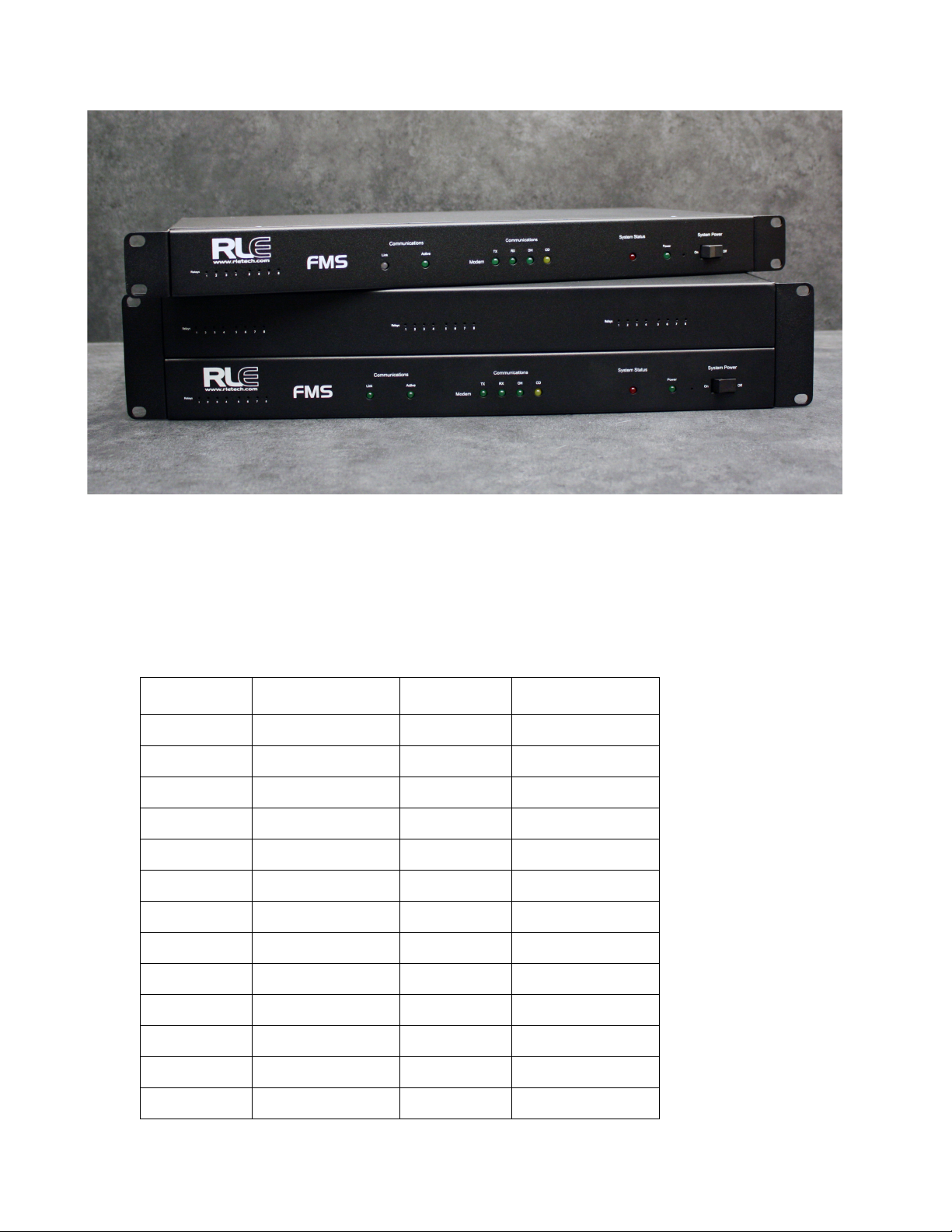
1.2. 1U and 2U FMS Devices
A base FMS unit ships in a 1U rack-mount enclosure. Up to four expansion cards can be added
to the base FMS to increase the functionality of the device. The 1U enclosure has room for one
expansion card, in addition to the base FMS unit. A 2U FMS has room for three expansion
cards, in addition to the base FMS functionality. If you add more than one expansion card to a
base FMS, your device will be upgraded to a 2U rack mount enclosure.
Refer to Appendix A, “FMS Expansion Cards” on page 179 to learn more about the different
FMS expansion cards and their capabilities.
rletech.com FMS User Guide 17
Page 18
1 System Overview
Status
LEDs
Status
LEDs
Network Modem
Expansion Card #1
Status LEDs
Expansion Card #2
Status LEDs
Expansion Card #3
Status LEDs
Expansion Card #4
Status LEDs
Status
LEDs
System
LED
Power
Power
Switch
System
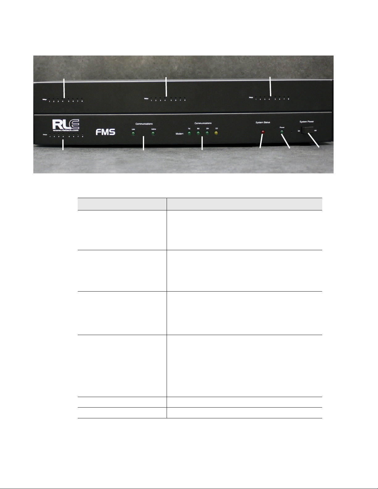
1.3. Front Panel Indicators and Controls
Figure 1.1
Indicator Description
Expansion Card Relay Status Only available on Expansion Card A, the green LED
Communication
Network Status LEDs
Communication
Modem Status LEDs
System Status LED Flashes red during initial boot up, approximately 30
Power LED Green when the power is on.
FMS 2U Front Panel Indicators and Controls
illuminates when the relay is active.
Expansion Card #1 LEDs are on the left hand side of
the 1U FMS enclosure. Expansion cards #2, #3, and
#4 are located across the top of the 2U FMS enclosure.
Link – Green if network link is established. Red if there
is no connection.
Active – Illuminated green when transmitting or
receiving data.
TX - Green when information is being transmitted.
RX - Green when if information is being received.
OH - Green when he Modem detects a dial tone (off
hook).
CD - Yellow when if a carrier is detected.
seconds.
If the initial boot up fails, the LED continues to flash.
This indicates a condition that requires service; users
must contact RLE for more information.
After the boot up, this LED turns off if no alarms are
present, or turns solid when the unit is in an alarm
condition.
18 FMS User Guide 800.518.1519
System Power Switch Use this switch to turn power to the unit on and off.
Page 19

1.4. Terminal Block Designations
1 System Overview
Figure 1.2
TB1-1 (+) Input for 24 or 48VDC (optional) power
TB1-2 (-) Input for 24 or 48VDC (optional) power
P1 24VDC wall adapter input (center +) (not available with 48VDC version)
TB2-1 24VDC positive (+) external output (power for sensors)
TB2-2 24VDC positive (+) external output (power for sensors)
TB2-3 Channel 1 positive (+)
TB2-4 Channel 1 negative (-)
TB2-5 Channel 2 positive (+)
TB2-6 Channel 2 negative (-)
TB2-7 Channel 3 positive (+)
TB2-8 Channel 3 negative (-)
TB2-9 Channel 4 positive (+)
TB2-10 Channel 4 negative (-)
FMS Terminal Block Designations
TB3-1 Channel 5 positive (+)
TB3-2 Channel 5 negative (-)
TB3-3 Channel 6 positive (+)
TB3-4 Channel 6 negative (-)
TB3-5 Channel 7 positive (+)
TB3-6 Channel 7 negative (-)
TB3-7 Channel 8 positive (+)
TB3-8 Channel 8 negative (-)
TB3-9 24VDC ground external output (power for sensors)
TB3-10 24VDC ground external output (power for sensors)
TB4-1 Relay 1 normally closed (NC)
Table 1.1
rletech.com FMS User Guide 19
Terminal Block Designations
Page 20

1 System Overview
TB4-2 Relay 1 normally open (NO)
TB4-3 Relay 1 common (C)
TB4-4 Relay 2 normally closed (NC)
TB4-5 Relay 2 normally open (NO)
TB4-6 Relay 2 common (C)
TB5-1 Keypad column 1
TB5-2 Keypad column 2
TB5-3 Keypad column 3
TB5-4 Keypad row 1
TB5-5 Keypad row 2
TB5-6 Keypad row 3
TB5-7 Keypad row 4
TB5-8 COM1 EIA-485 positive (+) (configurable)
TB5-9 COM1 EIA-485 negative (-) (configurable)
TB5-10 EIA-485 ground
SW1-1 Unit EIA-485 termination switch
SW1-2 Reserved for future use.
P2 COM1 EIA-232 male DB9 pin
P3 COM2 EIA-232 female DB9 pin connector (configurable)
P4 RJ11 telephone line connector
P5 RJ45 Ethernet 10/100BaseT connector
Table 1.1
Terminal Block Designations (continued)
20 FMS User Guide 800.518.1519
Page 21
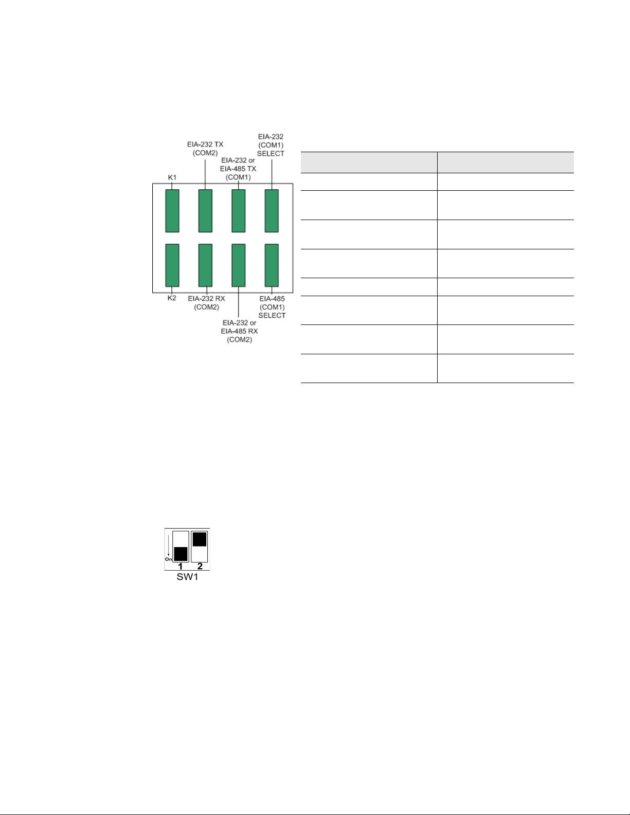
1.5. Rear Panel Indicators
The rear panel of the FMS houses a series of green LEDs.
The chart below tracks indicator status when the
corresponding green LED is illuminated:
Status Indicator
K1 (Output Relay) Relay is energized.
1 System Overview
EIA-232 TX (COM2)
Interface
EIA-232 or EIA-485 TX
(COM1) Interface
EIA-232 (COM1) Select
Interface
K2 (Output Relay) Relay is energized.
EIA-232 RX (COM2)
Interface
EIA-232 or EIA-485 RX
(COM1) Interface
EIA-485 (COM1) Select
Interface
Figure 1.3
Rear Panel Indicators
1.6. SW1 Switch Settings
♦ SW1-1: EIA-485 Termination switch should be in the down position (ON) if the FMS is an
end device on an EIA-485 network.
♦ SW1-2: Reserved for future use.
Data is being transmitted.
Data is being transmitted.
EIA-232 selected (P2)
Data is being received.
Data is being received.
EIA-485 selected (TB5)
Figure 1.4
SW1-1 Switch and SW1-2 Switch
SW1-1 switch is in the down position (ON) and SW1-2 switch is in the up position (OFF).
rletech.com FMS User Guide 21
Page 22

1 System Overview
22 FMS User Guide 800.518.1519
Page 23

To begin using the FMS, users must install the unit, wire and connect the power, and set the IP
WARNING
address. Any accessories for the FMS should also be connected at this time (e.g., keypad
connection, Modbus connections, Expansion Cards, etc.)
2.1. Installation
C HAPTER
CHAPTER 0GETTING STARTED
The Falcon FMS comes in a 19 inch (.48m) rack mount enclosure. Install the FMS in the rack.
Use the proper anchoring method to mount the unit securely. Supply either 24VDC (standard)
or 48VDC (optional) to the unit.
Units have different model numbers. Before applying power to the unit, verify the
model number and power rating located on the back of the unit. The voltage
indicator is the last number on the unit model number. The FMS will either be a
24VDC or a 48VDC.
2.2. Falcon FMS Wiring
RLE Technologies recommends an 18AWG stranded copper wire for connection from each
monitored point to a terminal block (TB) connection on the FMS. RLE recommends no more
than 500 feet (152.4m) of wire at this specification. If longer runs are needed, please contact
RLE Technologies for application guidance. Shielded twisted pair wiring is recommended for
analog signal transmitters being wired outside of conduit runs and dropped ceiling
applications.
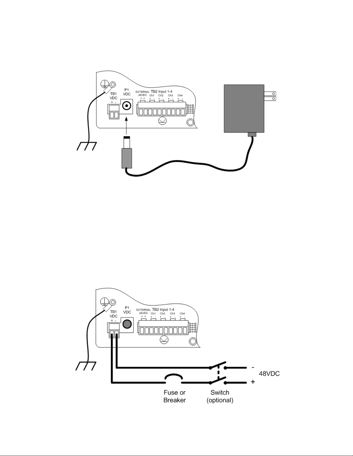
2.2.1 Power Supply and Ground Connections
Connect an 18AWG ground wire from the ground terminal to a suitable earth ground.
If you are installing a 24VDC model FMS, plug the wall adapter into P1 and a UPS outlet as
shown below. The wall adapter has a 5 foot (1.524m) power cord. RLE Technologies
rletech.com FMS User Guide 23
Page 24
2 Getting Started
recommends powering the FMS from a UPS supply to allow the FMS to send alarm
notification during a power outage.
Figure 2.1
24VDC Power Supply Connection
If you are installing a 48VDC FMS, the FMS must be connected to either:
a An external 48VDC supply that can be unplugged or switched off.
b The 48VDC supply bus via a switch or a circuit breaker. The switch or circuit breaker
must be suitable located and easily reached. It must be clearly marked as the
disconnecting device for the FMS.
For a 48VDC model FMS, connect a 48VDC supply through a circuit breaker to TB1 as
shown below. In telecommunications applications, the 48VDC supply is typically connected
to the 48VDC battery system through a DC distribution panel.
Figure 2.2
24 FMS User Guide 800.518.1519
48VDC Power Supply Connection
Page 25
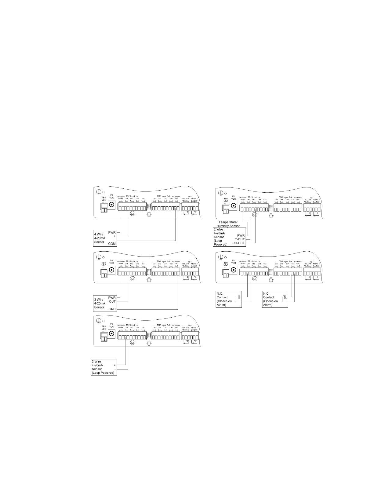
2.2.2 Universal Input Connections
The eight non-isolated universal inputs are connected to TB2 and TB3. Universal input
channels can be individually configured through the FMS to monitor a 4-20mA signal, a
Normally Open (NO) dry contact, or a Normally Closed (NC) dry contact; see Figure 2.3 for
examples of typical sensor wiring. See Appendix D, “FMS Accessories Wiring” on page 191,
for further details on wiring other RLE accessory sensors, or refer to our Falcon Integration
Guide, found online at http://rletech.com/resource/falcon-integration-guide/.
Some temperature and humidity sensors have internal jumper settings that may be used to
select sensor range and output voltage or current. Jumper settings should be set before power
is applied to the equipment. The sensor range (50–95°F, 22–122°F, etc.) should be
documented at this time. The sensor range is required to determine the gain and offset
settings when configuring the input through software.
2 Getting Started
Note The Falcon has 24VDC available (TB2-1, TB2-2 +24VDC, TB3-9, TB3-10 24VDC comm.) to
power external sensors. The 24VDC external supply is internally fused at 300mA.
Figure 2.3
Universal Input Wiring Examples
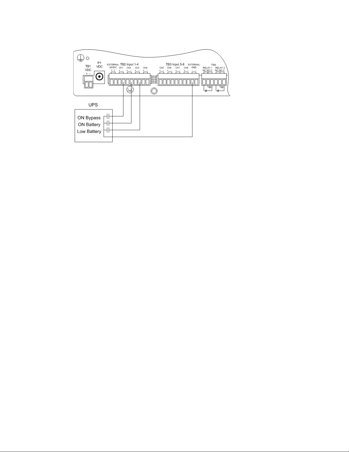
Some equipment may have several dry contact outputs with a Common Ground. Connect this
equipment as shown in Figure 2.4.
rletech.com FMS User Guide 25
Page 26
2 Getting Started
Figure 2.4
Dry Contact Inputs with Common Ground
26 FMS User Guide 800.518.1519
Page 27
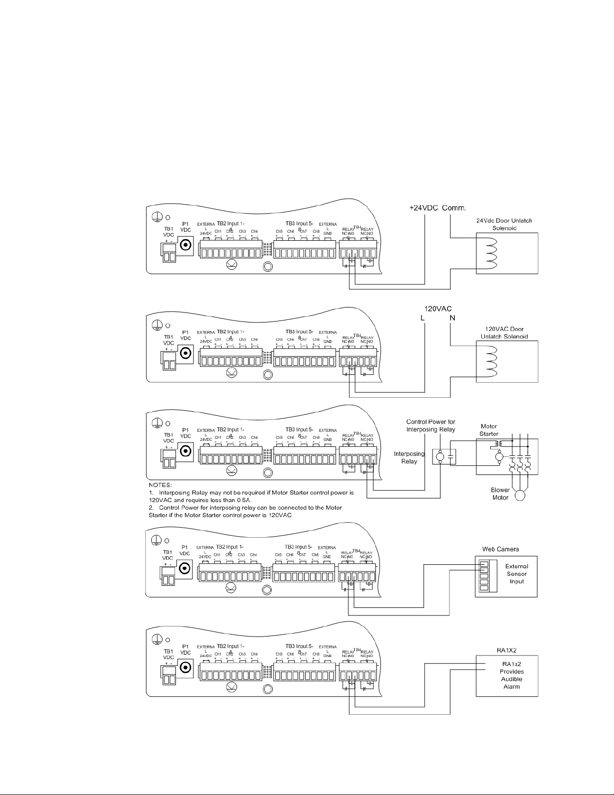
2.2.3 Relay 1 and 2 Connections
Relay outputs may be used to unlatch doors, signal annunciators, signal IP cameras, and to
turn on auxiliary equipment such as exhaust fans. Relay outputs are form c (spdt). Refer to
specifications in Appendix D, “FMS Accessories Wiring” on page 191, for relay contact
ratings. Relays may be configured, through the FMS for Normally Open (NO—unsupervised
or normally de-energized), or Normally Closed (NC—supervised or normally energized)
operation; see Figure 2.5 for examples.
2 Getting Started
Figure 2.5
rletech.com FMS User Guide 27
Relay Output Wiring Examples
Page 28
2 Getting Started
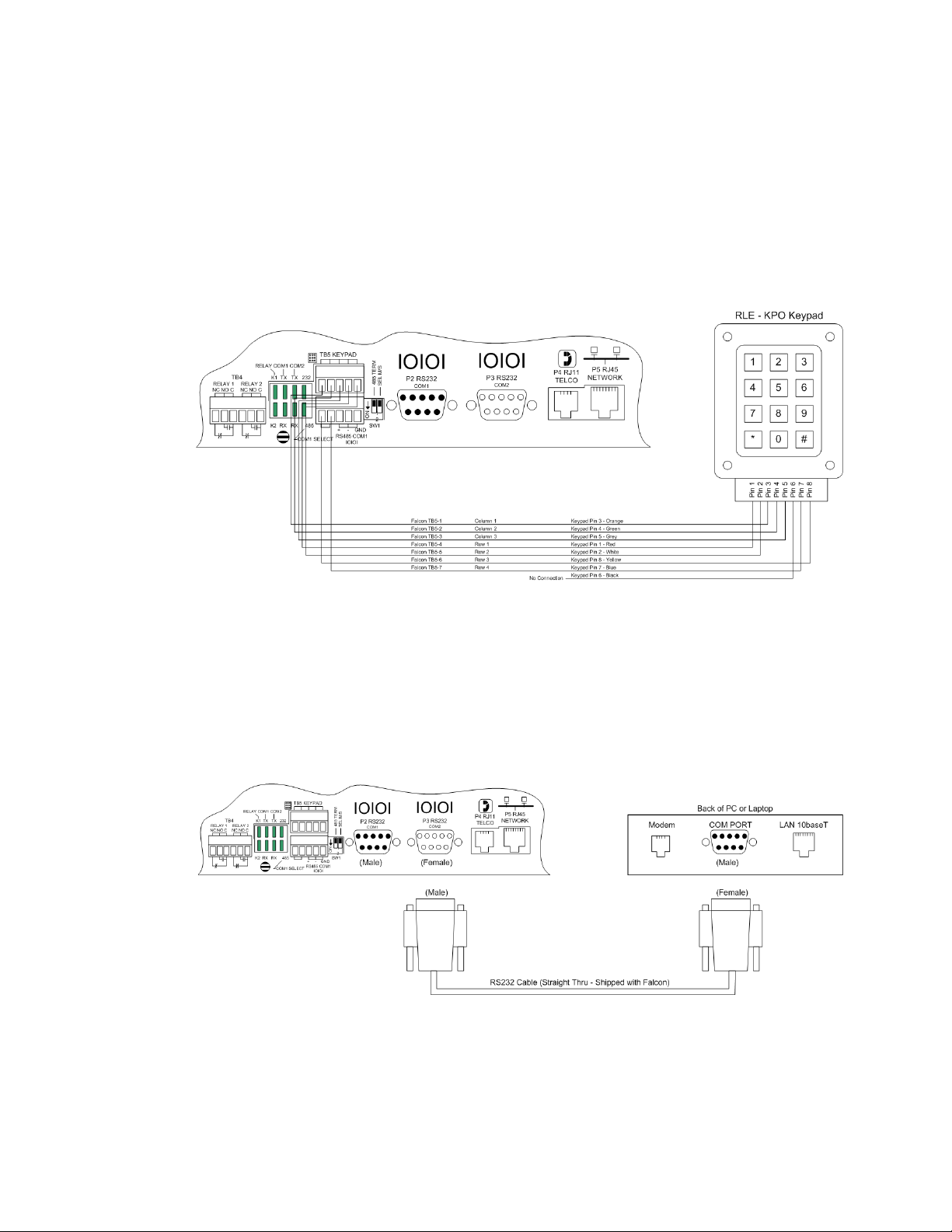
2.2.4 Keypad Connection
The FMS can be configured with a 3 x 4 keypad interface. Entering a user code, configured
through software, activates a relay output which unlatches a door and allows an individual to
enter the secure area. Entering the correct user code can also trigger a relay output to signal an
IP camera to snap a picture and email it to a predefined recipient. Connect the keypad as
shown in Figure 2.6. For more information on configuring the keypad function, see 4.15.,
“Keypad/DTMF Access Users” on page 77.
Figure 2.6
Keypad Wiring
2.2.5 EIA-232 COM2 Connection
The EIA-232 port can be connected to a PC for IP configuration, firmware downloads, and
troubleshooting. It is typically a temporary connection. Connect the straight through, 9-pin,
cable as shown in Figure 2.7.
Figure 2.7
EIA-232 COM2 Connection
28 FMS User Guide 800.518.1519
Page 29
2.2.6 RJ11 Phone Line Connection
The FMS may contain an optional internal modem for dial in and dial out capabilities. The
modem can be used for:
♦ Email notification through an Internet Service Provider (ISP).
♦ Remote connection to accomplish a variety of tasks, including: viewing alarms, changing IP
Configurations, and acknowledging alarms.
♦ Remote alarm acknowledgment and access through DTMF. This allows a user to dial the
FMS from a touch tone telephone-standard phone or cell phone-and enter an
acknowledgment code or access code.
♦ Pager notification to an alpha-numeric pager or cell phone (TAP changer).
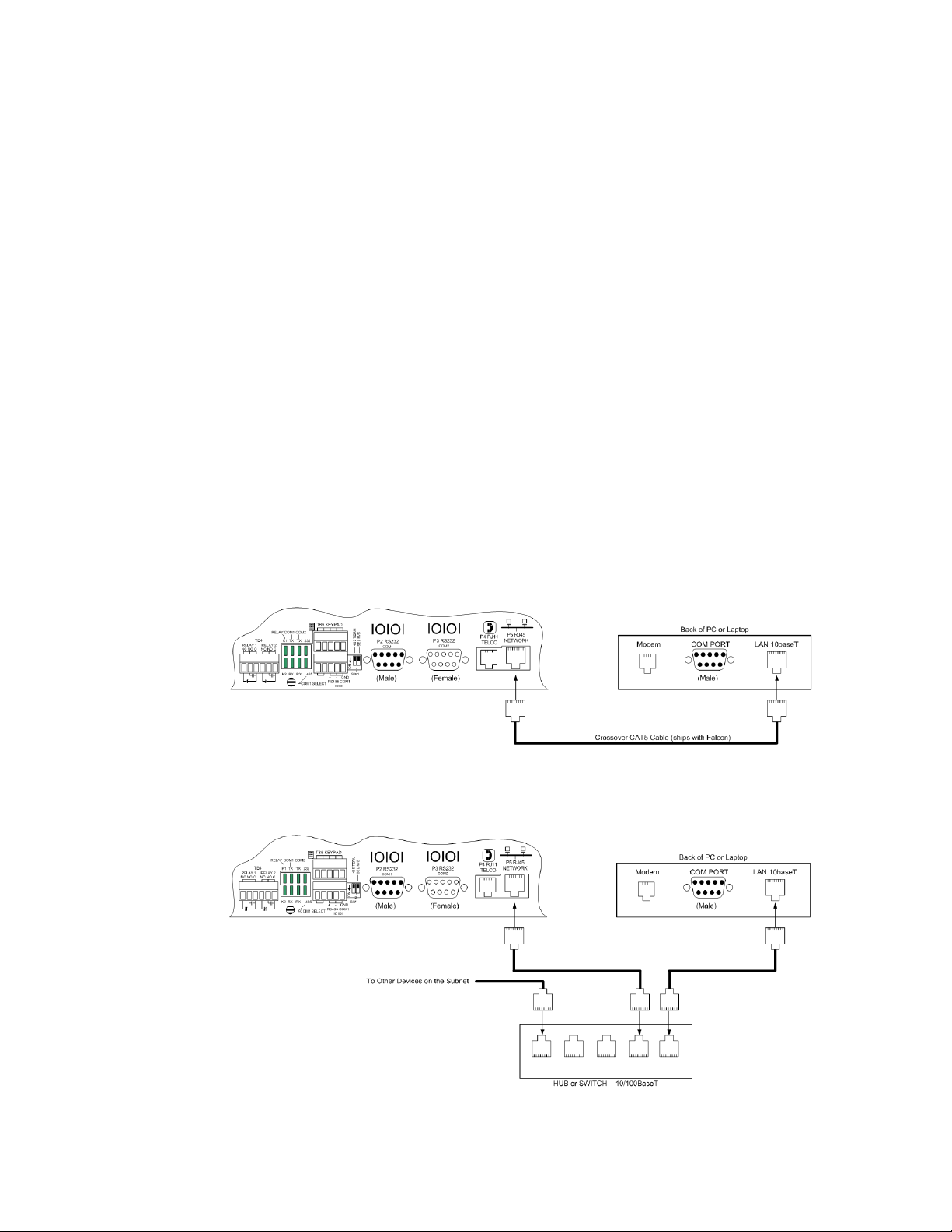
2.2.7 RJ45 Ethernet Connection
The FMS has an internal 10/100BASE-T Ethernet port used to configure and monitor the
FMS. The Ethernet port supports Web browser access, email (SMTP), BACnet slave, Modbus
slave, SNMP, BACnet master and Modus master. Figure 2.6 and Figure 2.7 show the physical
connections. Figure 2.8 shows a direct connection between the FMS and a PC using the
crossover cable supplied with the FMS. Figure 2.9 shows a typical FMS connection on a
subnet using a hub or switch and straight through CAT5 cables.
2 Getting Started
Figure 2.8
Figure 2.9
rletech.com FMS User Guide 29
FMS Ethernet Connection to a PC using a Crossover Cable
FMS Ethernet Connection to a PC on a Subnet
Page 30
2 Getting Started
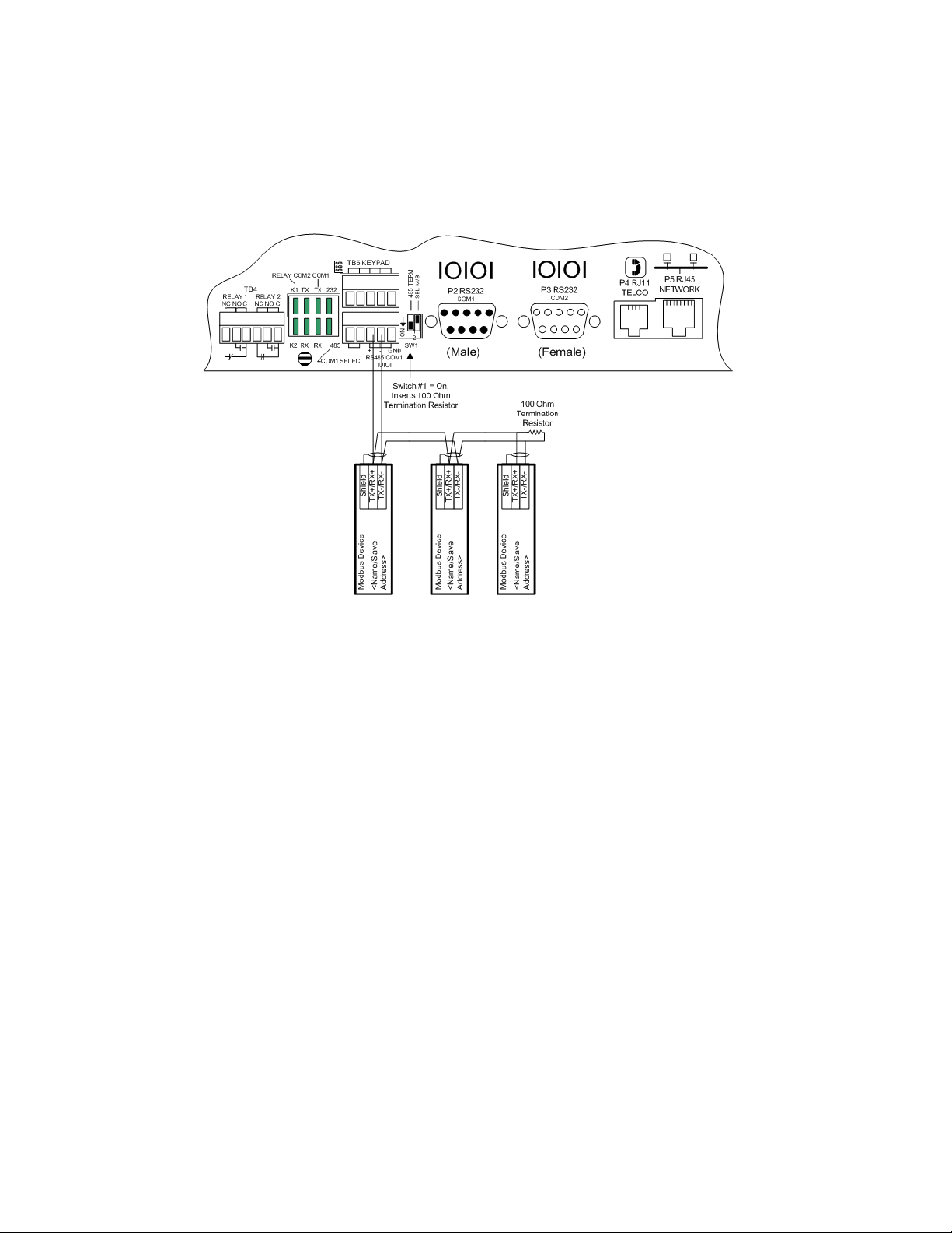
2.2.8 Modbus EIA-485 Connections
The FMS can function as a Modbus Master or Slave over an EIA-485, 2-wire hardware
connection.
Figure 2.10
FMS EIA-485 Connection
30 FMS User Guide 800.518.1519
Page 31

2.2.9 Modbus EIA-232 Connections
The FMS can function as a Modbus Master or Slave over an EIA-232 hardware connection.
The EIA-232 port is configured as a DTE device.
2 Getting Started
Figure 2.11
rletech.com FMS User Guide 31
FMS EIA-232 Connection to a DCE or DTE Device
Page 32

2 Getting Started
2.2.10 Expansion Card A Connections
A sticker identifying the expansion cards as A or C is located on each Expansion Card. The
following wiring diagrams show the Expansion Card in slot 1. However, the Expansion Card
may be in Slot 2, 3 or 4 based on the FMS configuration. The I/O for each card type appears on
the back of the FMS for reference during field wiring; see Figure 2.12 and Figure 2.16 for
typical wiring. For information on Expansion Card B, see Appendix A, “FMS Expansion
Cards” on page 179.
Expansion Card A has 12 non-isolated analog input channels and 8 relay output channels. The
analog input channels can be wired for 4-20ma, 0-5vdc, 0-10VDC, NO (normally open) dry
contact or NC (normally closed) dry contact. The circuit board has internal jumpers to select
an ma input or a voltage input. The factory default is set as a 4-20ma input. See Appendix A,
“FMS Expansion Cards” on page 179, for jumper location and settings.
Figure 2.12
I/O Terminals for Expansion Card A
Figure 2.13
32 FMS User Guide 800.518.1519
Analog Input Wiring for Expansion Card A
Page 33

2 Getting Started
Figure 2.14
Dry Contact Inputs with Ground and Relay Outputs, Expansion Card A
rletech.com FMS User Guide 33
Page 34

2 Getting Started
2.2.11 Expansion Card C Connections
Expansion Card C has 24 dry contact input channels.
Figure 2.15
I/O Terminals for Expansion Card C
Figure 2.16
34 FMS User Guide 800.518.1519
Typical Wiring for Expansion Card C
Page 35

2 Getting Started
2.3. Communication
The FMS will not communicate over a user’s network the first time it is connected to the
network. The manufacturer programs the FMS with a default IP address: 10.0.0.188, Subnet
Mask: 255.255.255.0. This default address must be changed to an IP address that corresponds
with the user’s network before the FMS can communicate over the network.
Follow the steps in this section to change the default address.
2.3.1 Set the FMS IP Address
There are three ways to set the FMS IP address:
♦ Via the ARP and PING commands
♦ Via the Web browser
♦ Via the EIA-232 interface
2.3.2 Set the IP Address Using the ARP and PING Commands
To set the IP address of a manufacturer programmed FMS, use the ARP (Address Resolution
Protocol) command together with the PING (ICMP echo request) command. To use the ARP,
you must know the Ethernet address of the FMS.
2.3.2.1 Obtain the Ethernet Address (MAC Address)
Each network device must have its own unique identification. This identification sets it apart
from all other manufacturers and ensures that no two network devices have the same address.
Each manufacturer must use a six digit numbering convention (six sets of two digits with both
letters and numbers). The first three digits determine the actual manufacturer, and the
remaining three digits determine the unique network serial number of each individual FMS.
A typical Ethernet address (also known as a MAC address - Media Access Control) from the
FMS looks like this: 00:90:5B:00:02:45
The Ethernet (MAC) address for the FMS is on the model number sticker located on the
bottom of the device.
2.3.2.2 Use the ARP Command
Once you know the Ethernet address of the FMS, use the ARP command with the correct
parameters from any computer located on the FMS subnet (e.g., Class C with a subnet of
255.255.255.0).
For example, enter the following from a command prompt:
arp -s 192.168.1.14 00-90-5b-00-02-45
This command tells the computer from which the ARP command was entered that the network
device with an IP address of 192.168.1.14 uses the Ethernet (MAC) address of
00-90-5b-00-02-45.
rletech.com FMS User Guide 35
Page 36

2 Getting Started
2.3.2.3 Use the PING Command
After the ARP command has been entered, the PING command must be entered from the same
computer in order to set up the IP address of the FMS. The PING command will use the ARP
entry added from 2.3.2.1, “Obtain the Ethernet Address (MAC Address)” on page 35, to send
the IP address information directly to the FMS (which is just one of several methods to
initially configure the IP address on a new FMS).
To do this, enter the following from a command prompt:
PING ip_address
Where “ip_address” is the IP address that was entered using the ARP command. In the above
example, the following would be entered:
PING 192.168.1.14
This command changes the IP address of the FMS to: 192.168.1.14.
2.3.2.4 Troubleshooting the ARP/PING Commands
If problems are encountered, it may be for one of the following reasons:
♦ The FMS already has a non-default TCP/IP address. Once the IP address of the FMS has
been changed from the default of 10.0.0.188, it is not possible to change it again with the
ARP/PING commands. This method of setting up the FMS IP address can only be used on
an FMS that still has its original default IP address, as shipped from the manufacturer.
♦ The device is not on the same Class C subnet as the computer from which the ARP/PING
commands were sent. The FMS default router and Subnet Mask must be changed via a Web
browser pointed at the FMS default IP address (i.e., http://10.0.0.188) or via a direct EIA232 terminal connection to the FMS-both of which are alternate methods for setting up the
FMS IP address.
2.3.3 Set the IP Address Using a Web Browser
1 Plug the blue and yellow crossover network cable that shipped with the FMS unit into the
laptop or workstation that will be used to configure the FMS. This cable is not intended to
be connected to a network hub.
2 Write down the computer's IP address and Subnet Mask. Then change the IP address and
Subnet Mask of the computer from its existing address to one that will allow it to
communicate with the FMS, such as 10.0.0.180. It may be beneficial to set the IP address to
one that is one number different from the FMS IP address. Consult the computer’s manual
or your IT Department before attempting this.
3 Connect the other end of the network cable to the Ethernet port on the back of the FMS.
Access the FMS through a Web browser by typing the IP address (10.0.0.188) into the
location bar. Enter the FMS user name and password when prompted.
Note The default user name is “falcon” and there is no default password – leave the password
field empty.
36 FMS User Guide 800.518.1519
Page 37

2 Getting Started
4 Select the Configuration Menu link, then select the System link. Select the IP
Configuration Menu link and change the IP address, Subnet Mask, and default Gateway to
one provided by the network administrator. Press the Submit Changes button. The FMS
will save the new IP address and reboot. Once the FMS reboots, the system status LED
stops flashing. Use the new IP address and reset the computer to its original IP address and
Subnet Mask.
5 Change the IP address of the computer back to its original IP address. If the computer was
configured as DHCP (the network domain controller assigns an IP address) return it to this
state. This may require assistance from your IT Department, or consult the computer’s
manual.
6 The computer and the FMS are now both configured to communicate on the network. Both
should be accessible via the network. Connect the PC and the FMS to the network. From
the PC Web browser, type in the IP address of the FMS. Enter the user name and password
as stated above to verify network access to the FMS.
2.3.4 Set the FMS IP Address using an EIA-232 Connection
To use the EIA-232 interface:
1 Connect the EIA-232 port (P3 - Com2) on the FMS to a terminal or PC running terminal
emulation software (HyperTerminal) with a 9-pin male-female straight through serial cable.
2 Set the appropriate communication port to 9600 baud, NO parity, 8 data bits, 1 stop bit,
(9600/N/8/1), and no software or hardware flow command.
3 Once the terminal emulation software starts, press Enter on the keyboard and the FCF>
should appear. If the FCF> does not appear, check the communication settings and make
sure the unit is powered on.
4 IP Address: From the FCF> type “IP” then press <enter> to view the current IP address.
To change the IP address, type IP, <space> and the new address to be assigned, then press
the enter key, example: IP 192.168.1.225 <enter>.
5 Subnet Mask: From the FCF> type “NM” then <enter> to view the current Netmask
address. To change the Netmask address, type NM, <space> and the new address to be
assigned, then press the enter key, example: NM 255.255.255.243 <enter>.
6 Default Gateway: From the FCF> type “DG” then press <enter> to view the current
Default Gateway address. To change the Default Gateway address, type DG, <space> and
the new address to be assigned, then press the enter key, example: DG 192.168.1.1 <enter>.
7 Every time you make a change the Falcon FMS will automatically save the changes.
See Chapter 5, “EIA-232 Interface” on page 161, for more information on the EIA-232
command set.
rletech.com FMS User Guide 37
Page 38

2 Getting Started
38 FMS User Guide 800.518.1519
Page 39

C HAPTER
CHAPTER 0WEB INTERFACE CONFIGURATION
The FMS Web interface provides a convenient way to check and monitor the FMS status
through a web browser.
To access the FMS web interface, you must first have configured the FMS to communicate on
your network. If you haven’t done this already, refer to Chapter 2, “Communication” on
page 35.
Once the FMS is communicate on your network, type the IP address of the FMS into the
location bar of the Web browser. When the prompt appears, enter the FMS’s default user name
(falcon) and password - the FMS is shipped without a user name so leave this field blank.
Press Enter.
3.1. Home Page
The top of the page provides links to other pages for additional monitoring, control and
configuration. The sections in this chapter will explain the functionality available on each
screen within the web interface.
The main page within the web interface acts as a dashboard for the FMS. This page is highly
customizable - you can change everything from the logo that appears in the upper left corner
of the page, to the way the inputs display in the middle of the page, to the interactive map and
camera view that can occupy the space on the right side of the dashboard. Many of the home
page specific options are configured via “Input Groups” on page 60.
rletech.com FMS User Guide 39
Page 40

3 Web Interface Configuration
Once it’s configured, the FMS home page may look similar to this:
Figure 3.1
Configured FMS Home Page
As you can see in our example, each input has a box with its number, name, and status. The
box is shaded to signal the inputs status. Color codes are as follows.
Color Description
Green Input is normal-not in an alarm state.
Yellow Analog inputs only-input is in a high alarm 1 or low
alarm 1 state.
Red Analog input is in a high alarm 2 or low alarm 2 state.
Digital input is in an alarm state.
Blue Alarm/Input disabled by a schedule.
White (no shading) Input is not configured-spare point for future use.
Magenta, Green, or Gold Digital Status point is on. This color is configurable
under the System Configuration Menu.
Table 3.1
Color Definitions
Note the XML Status link in the middle right side of the page. This link allows a user to
download data collected by the FMS as an XML file and then import it into a spreadsheet for
viewing, logging, and analyzing. If you’d like to save this file from the web interface, right
click on the link and select “Save Target As”. If you left click on the link, you will just be able
to view the information.
40 FMS User Guide 800.518.1519
Page 41

3.2. Alarms
The Alarms page provides a single view of all active alarms on the FMS unit.
3 Web Interface Configuration
Figure 3.2
Field Description
Date/Time The time the alarm was triggered.
Input The input that is alarm. This is a clickable link. If the link
Description The label description that you have entered for this input.
Type The type of input, as recorded on the input’s configuration
Severity The severity level of the alarm.
Present Value Indicates the current status of the input.
Alarm Description Provides a more complete description of the alarm condition.
Alarms Menu
connects to a slave unit, use the link to learn more about the
alarm condition. Otherwise, click this link to go directly to the
Configuration page for the input.
screen
rletech.com FMS User Guide 41
Page 42

3 Web Interface Configuration
3.3. Identity
The Identity link displays basic FMS information including Model Number, System Name,
MAC Address, which Expansion Cards are installed in which slots, Firmware Version, and IP
Address. Most of these values can be adjusted through the Configuration screens. This page is
intended for reference only, not system adjustment.
Figure 3.3
Identity Menu
42 FMS User Guide 800.518.1519
Page 43

3.4. Configuration
The Configuration page allows authorized users with administrator or read-write privileges to
adjust the FMS settings. Each link on the Configuration page displays more information about
specific configuration settings.
3 Web Interface Configuration
Figure 3.4
NOTE: If any of the fields within the sub-menus are edited, be sure to click the Submit
Changes button to save the changes. If you edit the fields and navigate from the web
pages without clicking the Submit Changes button, all changes will be lost.
Configuration Page
3.4.1 Inputs and Relays
Inputs and Relays allows users to program specific parameters for each FMS input and relay.
Only installed inputs and relays are displayed.
Different FMS models allow different numbers of inputs and relays. A1U will include the
Main Board inputs, and has room for one expansion card - either an A card or a C card.
A 2U FMS allows 4 expansion cards to be added to the unit - each expansion card slot can be
outfitted with either an A card or a C card.
♦ Main Board Inputs 1-8 - Every FMS has a main board. This board provides 8 inputs
configurable as analog 4-20mA or digital NO/NC.
♦ Expansion Card A Inputs and Outputs- adds an additional 12 inputs, configurable as analog
4-20mA, 0-5V, 0-10V or digital NO (cannot be configured as NC), as well as 8 form C
relay outputs.
♦ Expansion Card C Inputs - adds an additional 24 digital NO/NC inputs. There are no
additional relay outputs on a C card
rletech.com FMS User Guide 43
Page 44

3 Web Interface Configuration
.
Figure 3.5
FMS Input Configuration Menu
Inputs and relays located on expansion cards are identified by their name and slot channel
number, referred to in the Inputs table as S.Ch. For example, an input with a S.Ch number of
1.9 is located on the expansion card in slot one, and is the 9th input on that card. An input with
a S.Ch number of 4.2 is located on the expansion card in slot 4, and is the 2nd input on that
card. If an input has no S.Ch number, that means it is located on the FMS’s main card.
Relays work the same way. A relay with no S.Ch number is located on the FMS’s main board.
A relay with an S.Ch number of 1.4 is located on the expansion card in slot 1, and is the 4th
relay on that card.
Clicking an input link will display one of three input configuration pages - each card has its
own configuration page. Only the options available for the particular inputs on the card will be
displayed.
Relay configuration works the same way. Click a relay link to display that relay’s
configuration information. Only the configuration options available for that particular relay
will appear.
You’ll notice a link placed between the Inputs and Relays tables:
Option Description
Download Points
List Export CSV
Table
Table 3.2
44 FMS User Guide 800.518.1519
Inputs and Relays Configuration Page - Additional Link
Click this link to view a CSV list of all the inputs configured on this
FMS unit.
Page 45

3.4.1.1 Main Card - Input Channels 1-8
Inputs 1 - 8 reside on the FMS’s main circuit board. Click the input you’d like to configure.
The number of the input you’re configuring appears in the bar at the top of the configuration
page. Depending on which type of input you’re configuring, you’ll have different menu
options. The following table should address all the options available across the different input
types.
3 Web Interface Configuration
Note Users must push the Submit Changes button after they configure each input. Changes not
submitted before proceeding to the next input will be lost.
Figure 3.6
Option Description
Current Readings Displays the input current as sensed by the FMS and the calculated
Next Input /
Prev Input
Table 3.3
rletech.com FMS User Guide 45
FMS Main Board Input Configuration
value which factors in the designated gain and offset settings.
Click these links to advance to the next installed FMS input, or
move back to the previous input.
FMS Main Board Configuration Options
Page 46

3 Web Interface Configuration
Option Description
Select Input Type Select Input Type: Select the correct input type based on the type
Table 3.3
of device connected to the input channel. Options include:
• Not Configured: Select when there is nothing connected to the
input.
• Analog 4-20mA: Select when the device connected to the
input provides a 4-20mA output.
• Digital NO: Select when the device connected to the input is a
dry contact that is normally open and closes on an alarm
condition.
• Digital NC: Select when the device connected to the input is a
dry contact that is normally closed and opens on an alarm
condition.
• Digital Status: Select when the device connected to the input
is a dry contact that should only be monitored for status, and
will not need to report alarm conditions.
Select the way you’d like the information to:
• Physical: This allows you to configure the channel to display
inputs that are wired to the FMS (Channels 1 - 104).
• Import: This allows users to import Modbus data to a physical
point. Through this feature you can display Modus Register
information on the main page of the FMS and use Modbus
information to trigger other events and responses. Virtual Slots
can be added to the main page of the FMS to display more
Modbus Points; see Chapter 4, “Advanced Communications -
Modbus, BACnet, and Telnet” on page 133 for more
information.
FMS Main Board Configuration Options
46 FMS User Guide 800.518.1519
Page 47

3 Web Interface Configuration
Option Description
Gain & Offset Inputs like temperature, humidity, pressure, etc. connected to the
FMS convert information to a 4-20mA signal. The FMS reads this
raw 4-20mA signal and calculates a value based on the input and
the predetermined gain and offset settings. The idea is to determine
the correct gain and offset values so that the FMS calculates and
displays an accurate reading. Without setting the correct gain and
offset, the FMS will not convert the raw data correctly. As a result,
missed alarms or nuisance alarms could occur.
To set gain and offset values, click the Calculator link.
Enter the sensor’s range and press the Calculate button. Click the
Return to Input 1 Configuration link so that the gain and offset
fields are automatically entered with the correct offset and gain
settings. Gain and offset values can also be determined by using
the following formulas:
Table 3.3
Gain for 4-20mA Transducer = (Sensor High Range ValueSensor Low Range Value) / 4
Offset for 4-20mA Transducer = Sensor Low Range Value Gain
Example: Temperature sensor with a sensing range of 50-95°F displayed in Fahrenheit
Gain = (95-50) / 4 = 11.25 | Offset = 50 - 11 = 38.75
Example: Temperature sensor with a sensing range of 50-95°F displayed in Celsius
Convert 50-95°F to 10-35°C and use the Celsius range for the
calculations
Gain = (35-10) / 4 = 6.25 | Offset = 10 - 6 = 3.75
Example: Humidity sensor with a range of 0 - 100% RH
Gain = (100-0) / 4 = 25 | Offset = 0 - 25 = -25
Gain for 0-5V or 0-10V Transducer = Sensor High Range ValueSensor Low Range Value
Offset for 0-5V or 0-10V Transducer = Sensor Low Range Value
Example: A 0-5V Transducer with a range of -30-175°F
Gain = 175 - -30 = 205 | Offset = -30
Example: A 0-5V Transducer with a range of 0 - 100%RH
Gain = 100 - 0 = 100 | Offset = 0
FMS Main Board Configuration Options
rletech.com FMS User Guide 47
Page 48

3 Web Interface Configuration
Option Description
Hysteresis Applies when the input type is Analog 4-20mA and is active for High
UOM/Map Label The 10 character field used to assign a unit of measure label to
Limit 1, High Limit 2, Low Limit 1 and Low Limit 2.
Hysteresis (also referred to as deadband) designates the amount
an input reading must sway from its preset alarm reading before it
is classified as returned to normal. It effectively provides a
deadband around the limit settings, which prevents sensors from
sending multiple alarm and return to normal alerts when the
sensor’s value hovers around its alarm limit.
Example: A temperature sensor alarms when it reaches its High
Limit 1 of 80°F. If Hysteresis is set at two, the sensor must register
less than 78°F before the FMS reports it as returned to normal.
In another example, a humidity sensor alarms when it reaches its
Low Limit 2 of 30% RH. If the Hysteresis is set at five, the humidity
must register more than 35% before the FMS reports it as returned
to normal.
analog values, such as °F, °C, % RH, Amps, Volts, PSI, etc. The
unit of measure field is only required when the input type is Analog
4-20mA. The unit of measure field is displayed on the Main Menu
and in notification (email/pager messages and SNMP Trap).
Alarm Delay The amount of time the FMS waits to send an alert after an alarm
condition is detected. The FMS uses this same time delay to report
a return to normal after the alarm condition clears. The alarm delay
is active for all input types except Not Configured.
Example: An CRAC unit input is configured with an alarm delay of
10 seconds. If the CRAC unit goes into alarm and then returns to
normal within10 seconds, no alarm is generated in the FMS.
If the CRAC unit remains in alarm for 10 seconds or more, the FMS
records the alarm and generates notification per the input settings.
If the CRAC unit returns to normal but then alarms again within 10
seconds, the FMS does not record this as a return to normal. Once
the CRAC unit returns to normal for greater than 10 seconds, the
FMS records a return to normal and generates its notifications.
High Limit2 (Major) Applies only to analog 4-20mA inputs.
The FMS will record an alarm and send notification when the FMS
calculated value exceeds this limit. The High Limit 1 and High Limit
2 are disabled when they are both set to 0. High Limit 2 will also
activate any designated relays.
High Limit1 (Minor) Applies only to analog 4-20mA inputs.
The FMS will record an alarm and send notification when the FMS
calculated value exceeds this limit. The High Limit 1 and High Limit
2 are disabled when they are both set to 0.
Table 3.3
FMS Main Board Configuration Options
48 FMS User Guide 800.518.1519
Page 49

3 Web Interface Configuration
Option Description
Low Limit1 (Minor) Applies only to analog 4-20mA inputs.
The FMS will record an alarm and send notification when the FMS
calculated value falls below this limit. The Low Limit 1 and Low
Limit 2 are disabled when they are both set to 0.
Low Limit2 (Major) Applies only to analog 4-20mA inputs.
The FMS will record an alarm and send notification when the FMS
calculated value falls below this limit. The Low Limit 1 and Low
Limit 2 are disabled when they are both set to 0. Low Limit 2 will
also activate any designated relays.
Pager Alarms Use the Configuration>Modem/Phone Numbers/Pagers link to
configure alarm recipients. You can configure up to 15 phone
numbers, and each will go into a numbered slot, 1 - 15.
Then come back to this field and designate up to five recipients who
should be notified when this point goes into alarm. Separate the
recipients’ ID numbers with commas. The FMS will first dial the
lowest number listed, regardless of the order in which the numbers
are listed.
Enter zero to disable this feature.
Example: If the Alarm dial out string is set to “3, 5, 1, 0, 0,” the FMS
will dial Pager #1, Pager #3 and then Pager #5 when an alarm
occurs. Pager notification will be sent when an input alarms (high
limit 2, high limit 1, low limit 1, low limit 2 is exceeded or the digital
input is in alarm). See 3.4.13, “Modem/Phone Numbers/Pagers” on
page 78 for more information.
Label Enter a unique name for this input.
Applies to all input types except “Not Configured.”
• For Analog input types, this label is displayed on the FMS Main
Menu and the Input Configuration Menu. When the input
alarms and/or returns to normal, the label is included in the
Alarm History and notification messages.
• For Digital NO and Digital NC inputs, the label is displayed on
the FMS Main Menu, Input Configuration Menu, Alarm History
page and in notification messages only when the device is in
alarm.
• For Digital Status inputs, the label is displayed on the FMS
Main Menu when the input is on. When the input turns on, the
label is also included in the Digital Status History.
Table 3.3
FMS Main Board Configuration Options
rletech.com FMS User Guide 49
Page 50

3 Web Interface Configuration
Option Description
Label (Digital input
Applies to input types Digital NO, Digital NC and Digital Status.
normal)
This label is displayed on the main page when the input is normal,
in the Alarm History when the input returns to normal and in
notification messages. For Digital Status inputs, the label is
displayed on the Home page when the input is off. When the input
turns off, the label is also included in the Digital Status History.
This field may be left blank. If it is left blank, the FMS displays the
Label (from above).
“OR Gate” Relay (1-
16) Control
and
This uneditable field reflects information entered on this specific
relay’s configuration screen. Access the configuration page for this
relay to edit these fields.
“OR Gate” Relay
(17-32) Control
Relay Configuration
Link
Used to assign a High Level 2, Low Level 2, or Digital Alarm
generated by this input to the OR gate function block of the Relay
Control Logic to a specific relay. To select the relay(s), click on the
link and check the relay box(es). See Appendix G, “Relay Control
Logic” on page 213.
Group Assignment Use the Configuration>Input Groups link to configure up to 8 groups
into which you can organize your inputs.
Then return to this page and determine whether your input should
be placed into one of those groups.
If this input should be part of a group, specify that group’s number
here.
Digital Alarm
Severity
The FMS allows you to set a digital output alarm code.
Choose from Critical, Major, Minor, or Warning in the drop down
menu.
Email Recipient
Notification
Use the Configuration>Email/DNS link to configure email
addresses that can receive alarms from the FMS. You can
configure up to 8 email addresses, and they will each go into a
numbered slot, marked 1-8.
Email addresses will be displayed next to the checkboxes on this
page once they are configured on the Email Configuration page.
Use the checkboxes to eight email addresses for notification if the
input goes into alarm. Email notification will be sent to recipients
whose names are checked when an input alarms and, if
designated, when an alarm returns to normal.
Email URL Link Email links can be included in FMS notification - popular links
include links to emergency recovery plans and links to user guides.
If you’d like, you can include one URL link in each email message.
Use the Configuration>Email URL Links page to set up the URL
links, and then enter the number associated with the link you’d like
to send here.
Table 3.3
FMS Main Board Configuration Options
50 FMS User Guide 800.518.1519
Page 51

Option Description
3 Web Interface Configuration
Alarm Disable by
Schedule
Use the Configuration>Schedules link to define a timeframe for
Schedules A and B.
Then return to this page and use this field to designate a period of
time the input will be disabled or inactive. To do this, select either
the A or B schedules.
Within the scheduled time, the point on the Main Menu will turn
Blue to indicate that the input is currently being disabled during its
scheduled time. Once the scheduled time has passed, the point will
reactivate and return to its normal color.
Input Polarity
Reversal by
Schedule
If this input is Digital NO/NC, you may need to reverse the input
polarity at certain times of the day. Use the
Configuration>Schedules link to define a timeframe for Schedules
A and B.
Then return to this page and use this field to designate a period of
time the input polarity will be reversed. To do this, select either the
A or B schedules.
Snmp Trap Use this feature to enable or disable SNMP traps. The trap can also
be disabled during one of the schedules that was established on
the Configuration>Schedules page.
Snmp Trap
Recipients
Use the Configuration>SNMP/Syslog page to set up your SNMP
Communities. Once communities are configured, their IP address
will appear next to the checkboxes in these fields.
Check the boxes of the recipients that should receive messages
when this input goes into alarm.
High1/Low1 Snmp
Traps
Used to disable SNMP notification for the first level analog alarm.
Notification is not sent until alarm reaches the more critical level 2.
Snmp OID The SNMP OID is provided here for informational purposes only.
Display Value Used to show either Signed or Unsigned Values for the displayed
value calculated by the FMS.
Example: If a selected value is Unsigned, the FMS will not display a
negative number on the calculated reading.
Table 3.3
FMS Main Board Configuration Options
rletech.com FMS User Guide 51
Page 52

3 Web Interface Configuration
Option Description
Individual Ground
Type (digital in only)
Only applies to Digital Inputs.
Defines the type of digital input as either Individual Ground or
Common Ground.
• Individual Ground: Used if the monitored input is a single
relay contact and two contacts- common and NO or NC-are
accessible.
• Common Ground: Used if multiple relays are to be monitored
that have the commons bussed or tied together (only one
common input connection) and only the NO or NC contacts are
available for each individual relay output. See the example
below or see 2.2., “Falcon FMS Wiring” on page 23, for more
information.
Example: Configure input channels 1-2 for Individual Ground, and
configure input channels 4-6 for Common Ground:
Figure 3.7
BACnet Instance The BACnet object identifier. It is a numerical code used to identify
the input. This code must be unique within the BACnet device.
BACnet Units A numerical code used to assign engineering units to this BACnet
Instance. Refer to the BACnet standard for further information.
The next five rows contain information that pertains to graphical mapping. If you’d
like more information regarding mapping, refer to ####
Map Box Size If you’re creating an interactive map for your facility, this field is
helpful. It allows you to customize the size of the mapped object for
this input point.
By default, the height of the object, as it appears on the map, is
approximately 20 pixels, and the width automatically adjusts to the
length of the text. This setting allows users to expand the size of the
object to fill a defined area.
Table 3.3
52 FMS User Guide 800.518.1519
FMS Main Board Configuration Options
NOI/NC Wiring Example
Page 53

3 Web Interface Configuration
Option Description
Text Direction Used for graphical mapping - decide if you’d like the text on the
map for this object (temperature reading, humidity reading, sensor
value, etc.) to be horizontal or vertical.
Map Coordinate Fine tune the location of the object on the map. Refer to “Facility
Mapping” on page 129 for further information.
Graphical Mapping Designate the device’s location on the FMS graphical map.
Test Map View the mapped location of the point you’re currently configuring.
Digital Input Color Active and Inactive
Inputs configured for Digital Status do not trigger notification.
Instead, use this option to set the display color for Digital Status
points on the Main Menu when the input in its inactive state, and
also when it is turned on to its active state.
The options include red, gold, magenta, gray, and green.
Typically, points are configured to be green in their inactive state
and then to turn red on alarm.
Table 3.3
FMS Main Board Configuration Options
Note Press the Submit Changes button when done to save all changes.
rletech.com FMS User Guide 53
Page 54

3 Web Interface Configuration
3.4.1.2 Expansion Card “A” Input Configuration
Expansion Card A contains 12 inputs, configurable as analog 4-20mA, 0-5V, 0-10V(analog 0-
5V and 0-10V require additional jumper configuration) or digital NO (cannot be configured
as NC), plus 8 form C relay outputs.
While units will vary depending on individual configurations, inputs for Expansion Card A are
typically numbered 1.1-1.12, 2.1-2.12, etc.
This page will be displayed when configuring an input on an Expansion Card A. It is identical
to the FMS Main Board Input Configuration page—see 3.4.1.1, “Main Card - Input Channels
1-8” on page 45—with the following exceptions:
♦ The Expansion Card “A” does not except common ground digital inputs. Therefore, the
option for Individual Ground Type (digital input only) is removed.
♦ Analog 0-5VDC and Analog 0-10VDC options are added to the Input Type. The Expansion
Card “A” accepts analog inputs individually configurable through internal jumpers, as
4-20mA, 0-5VDC or 0-10VDC.
Figure 3.8
54 FMS User Guide 800.518.1519
Expansion Card A Configuration Page
Page 55

3.4.1.3 Expansion Card “C” Input Configuration
Expansion Card C contains 24 digital NO/NC inputs.
While units will vary depending on individual configurations, Expansion Card C is typically
numbered 1.1-1.24, 2.1-2.24, etc.
This page will be displayed when configuring inputs for Expansion Card C. It is similar to the
FMS Main Board Input Configuration page – see 3.4.1.1, “Main Card - Input Channels 1-8”
on page 45—with the following exceptions:
♦ The Input Type options do not include Analog 4-20mA since Expansion Card “C” only
accepts dry contact inputs.
♦ The Gain, Offset, Hysteresis, Unit of Measure, High Limit 2, High Limit 1, Low Limit 1,
and Low Limit 2 are not available since Expansion Card “C” does not accept analog inputs.
♦ The option for Individual Ground Type (digital input only) is removed. Expansion Card
“C” accepts Individual and Common Ground inputs; however, it does not require any
software configuration.
3 Web Interface Configuration
Figure 3.9
Expansion Card “C” Configuration Page
3.4.1.4 Internal Temperature and Internal Humidity Configuration
Internal temperature and humidity sensors are optional, and are not included on all FMS
configurations. Internal Temperature, Ch. 105, and Internal Humidity, Ch. 106, have the same
options as a standard channel configured as an analog input, but the gain value cannot be
changed-it has a fixed value internally. The Input Type for Internal Temperature is used to
specify and display the input in Fahrenheit or Celsius.
rletech.com FMS User Guide 55
Page 56

3 Web Interface Configuration
3.4.2 Relay Configuration
From the Configuration>Inputs and Relays page, select the relay you’d like to configure. Then
use this page to configure the FMS’s relays.
Figure 3.10
Relay Configuration Page
56 FMS User Guide 800.518.1519
Page 57

3 Web Interface Configuration
Option Description
Type Each relay output can be configured for one of the following types-
only one type per relay output:
• NO (Non-Supervised): Configures the relay output to be
normally de-energized. The relay output will energize when
activated by an input or by a schedule. The silkscreen labeling
for the relay outputs (NC, NO and C) refer to the state of the
relay output when it is de-energized.
• NC (Supervised): Configures the relay output to be normally
energized. The relay output will de-energize when activated by
an input or by a schedule. The silkscreen labeling for the relay
outputs (NC, NO and C) refer to the state of the relay output
when it is de-energized.
• Force On: Energizes the relay out and allows a user with
Read-Write or Administrator privileges to turn on a relay output
for control or testing purposes.
• Force Off: Energizes the relay out and allows a user with
Read-Write or Administrator privileges to turn off a relay output
for control or testing purposes.
• Keypad Controlled: Configures the relay output to be
controlled by a keypad code or DTMF code. The User Code
Configuration link appears to the right of the Label field once
the Keypad Controlled option is selected and submitted. The
User Code Configuration link allows users to link which access
code will active the relay output.
Figure 3.11
Keypad/Relay Configuration
• Button Controlled: Adds a button to the Relay Control page
allowing users with Read-Only privileges to turn on or off a
relay output for control purposes.
• Modbus Controlled: Configures the relay output to be
controlled by a Modbus/SNMP Slave device in alarm.
Label Used for relay identification. This label appears on the Relay Status
and Relay Control pages.
BACnet Instance The BACnet object identifier. It is a numerical code used to identify
the input. This code must be unique within the BACnet device.
Table 3.4
rletech.com FMS User Guide 57
Relay Configuration Menu Options
Page 58

3 Web Interface Configuration
Option Description
OR'D Alarm IDs Displays the Alarm IDs of the inputs specified through the Relay
AND’d Alarm IDs Allows up to four Alarm IDs (High Limit, Low Limit or Digital Alarms)
Combo Gate The Combo Gate allows OR’d and AND’d IDs to be used in
Configuration link on the Input Configuration Menu. The Alarm IDs
displayed can be translated by using Appendix E, “Alarm ID
Reference Tables” on page 199. The Alarm IDs are also displayed
on the Input Configuration page. The Relay Control Logic diagram
in Appendix G, “Relay Control Logic” on page 213, shows how the
OR’d Alarm IDs, AND’d Alarm IDs and the Combo Gate are
internally connected.
to be specified for the AND Gate Function Block input of the Relay
Control Logic. Alarm IDs can be obtained from Appendix E, “Alarm
ID Reference Tables” on page 199. The Alarm IDs are also
displayed on the Input Configuration page. The Combo Gate
Function Block of the Relay Control Logic will either OR or AND the
OR'd Alarm and AND'd Alarm inputs together. The Relay Control
Logic diagram in Appendix G, “Relay Control Logic” on page 213,
shows how the OR'd Alarm IDs, AND’d Alarm IDs and the Combo
Gate are internally connected.
conjunction with each other. The Relay Control Logic diagram in
Appendix G, “Relay Control Logic” on page 213, shows how the
OR'd Alarm IDs, AND’d Alarm IDs and the Combo Gate are
internally connected.
On-Delay Time Specifies the number of seconds the Relay Control Logic will be
delayed before activating the relay on alarm.
On-Duration Time Specifies how long the relay will be active after a valid alarm
combination is recognized through the Relay Control Logic.
• A positive number entry in seconds will keep the relay in its
alarm state (activated) for the fixed period specified.
• A negative number entry in seconds will keep the relay in its
alarm state (activated) after the alarm condition has returned to
normal for the fixed period specified.
• A zero entry will configure the relay to be active until the alarm
condition returns to normal.
Latch Mode (NonLatching, Latching,
Silenceable)
Schedule Designates which of the schedules (None, A or B) the relay will
The next four rows contain information that pertains to graphical mapping. If you’d
like more information regarding mapping, refer to ####
Map Label Assign a label to this relay, so you can identify the point on the
Latching will cause the relay to latch, or remain in its alarm state,
when activated until it is reset by the user. If latching is selected, the
on-duration time function will be disabled.
follow. The schedules are specified in the Configuration Menu. If
schedule A or B is selected, all other function blocks of the Relay
Control Logic for that relay will be disabled. This allows the relay
output to be energized based on day-of-week and time-of-day.
graphical map.
Map Coordinate Fine tune the location of the object on the map. Refer to “Facility
Mapping” on page 129 for further information.
Graphical Mapping Designate the device’s location on the FMS graphical map.
Table 3.4
58 FMS User Guide 800.518.1519
Relay Configuration Menu Options
Page 59

3 Web Interface Configuration
Option Description
Test Map View the mapped location of the point you’re currently configuring.
Relay Logic Diagram This link displays the FMS’s relay logic diagram. Refer to Appendix
G, “Relay Control Logic” on page 213, for further information.
Table 3.4
Relay Configuration Menu Options
rletech.com FMS User Guide 59
Page 60

3 Web Interface Configuration
3.4.3 Input Groups
Sometimes it’s easier to monitor the status of inputs when they’re grouped together. The FMS
allows you to organize individual inputs into groups, that can then be displayed in their
grouped configuration on the FMS’s home page. You can also receive group alarm
notification via a single SNMP Trap and a single alarm notification coordinate on the
interactive map.
Use this page to establish input groups and notification settings. Then return to the individual
input configuration pages to designate which inputs should be placed into which groups - each
input has a Group Assignment field near the middle of the configuration page. Enter the
appropriate group number for each input to place the input in the group. When you return to
the FMS’s home page, you should see your inputs properly grouped within the main body of
the page.
Figure 3.12
60 FMS User Guide 800.518.1519
Input Groups Configuration
Page 61

3 Web Interface Configuration
Option Description
Input Groups Activate the Input Groups home page display with this option.
Disabled - No groups will display.
Enabled - Horizontal will display the groups together in rows.
Enabled - Vertical will display the groups together in columns.
Group This uneditable field specifies the group number.
Label Specify a name for the input group. This name will be displayed on
the FMS home page.
Description Designate a description for this group.
Snmp Traps When an input group SNMP is enabled, a falconInputGroupTrap is
generated in place of the individual input trap. The group label and
description are appended to the trap. Only one group trap is sent
when multiple alarms are present in that group. A clear trap is not
sent until all inputs of the group have cleared of an alarm.
The SNMP input group traps are escalating.
If you would like an SNMP trap sent for this group, enable that
feature here.
Mapping If you would like an icon for this group to display on the interactive
map, enter the box size and coordinates here.
Graphical Mapping link: Click this link to use the drag and drop
feature to place the icon on the graphical map.
Table 3.5
Input Groups Configuration Options
rletech.com FMS User Guide 61
Page 62

3 Web Interface Configuration
3.4.4 System
The System link lets you configure many of the FMS’s home page display options.
Figure 3.13
Option Description
MAC Address This field displays the MAC address, which is assigned to the FMS
IP Address The FMS’s IP address. If necessary, adjust the IP address here.
System Name Designate a name for the FMS. This name appears on the upper
Web Title Bar Text You can control the text that appears in the title bar of the web
Web Refresh Rate The web refresh rate is the amount of time the system waits until it
System Configuration
by the manufacturer. This field is uneditable, and is intended for
reference only.
left corner of the web interface, under the main horizontal menu.
The system name is also included as part of email notifications.
browser, and also on the tab for the web interface’s web page.
updates the web interface with current data. Typical setting are
between 15 and 30 seconds.
DO NOT set the refresh rate between 1 and 5 seconds. This can
cause the screen to freeze or lock up.
If the refresh rate is set to 0 the FMS will not refresh at all. Users
must set a refresh rate in order for the system to automatically
update.
Default setting: 0 seconds
Table 3.6
62 FMS User Guide 800.518.1519
System Configuration Options
Page 63

3 Web Interface Configuration
Option Description
PDA Screen Width Sets the width of the PDA web pages in the FMS to match the PDA
device. The PDA web pages can be accessed from the Web
browser by entering /pda after the IP Address (e.g., 10.0.0.188/
pda). The FMS includes a PDA web page view for the Main Menu,
Identity and Alarm History pages only.
Analog Average Allows users to change the averaging method for analog inputs.
Normally, the system samples analog points once a second while
tracking high and low values for each analog point. After sixty
seconds, the high and low values for these points and the average
of these readings are recorded in the Minute Log.
To alter this method of averaging, change the value to one of the
values listed in the drop down menu. Zero or one maintains the
method described above; a higher value changes the method of
averaging, and the manner by which high and low values are
recorded. See Appendix B, “Analog Averaging” on page 187.
HTML Main Page Determines the number of monitoring points displayed on the Main
Menu. With the default of “0,” the Summary Alarm Box, Internal
Temperature and Humidity Box and a link to View All Points are
displayed.
Settings greater than “0” will display the selected points with links to
the remaining points. Typically users display all installed points. If
the FMS is continuously monitored with a Web browser, it may be
desirable to set the HTML Main Page Points to “'0”' and monitor the
View all Points page.
Digital Status Active
Color
Determines the color of Digital Status points on the Main Menu
when the input is turned on. The options are green, gold and
magenta. Typically, points are configured to be green and turn red
on alarm. However, inputs configured for Digital Status do not
trigger notification. For these points, this setting determines the
color of the point when the input is on.
HTML Alarm History
Display
This option allows users to choose how alarms are acknowledged
in the Alarm History page. The FMS is defaulted to “And all
acknowledgments.” This means that at least two people must
acknowledge the alarm for the history to show it has been
acknowledged. If users want to allow only one person to
acknowledge the alarm to have the Alarm History page log it, select
the “Or the acknowledgments.”
Falcon Unit Map
Coordinate
You can add a link to this FMS home page to the FMS’s interactive
map. Use these fields to fine tune the coordinates of the FMS
Home Page link. Refer to Chapter 7, “Add a Link to the FMS Home
Page” on page 135 for further information.
Graphical Mapping If you’d rather drag and drop the FMS icon to adjust its location,
click the Graphical Mapping link.
Your FMS map will appear in the browser window. Drag and drop
the icon for this FMS (a capital F (F) in a shaded circle) until it is
where you would like it to be.
Click the Falcon Unit - Submit Changes link when you are done to
save your changes.
Table 3.6
rletech.com FMS User Guide 63
System Configuration Options
Page 64

3 Web Interface Configuration
Option Description
Default URL Designate the view you’d like to see when you type the IP address
of the FMS into your browser’s display bar.
• Home Page - displays the FMS’s home page (IP/index.htm)
• Alarms Page - displays the alarms page (IP/alarms.htm)
• Falcon Nest Map - displays the FMS nest map page
• Floor Map - displays the map loaded into the FMS as Map
Image#1. Go to the Configuration>Map page to upload an
image.
Button Controlled
Relay Password
Graph Type The FMS generates graphs for data trending. If you choose to use
Exit to Bootloader Click this link to access the FMS’s bootloader.
Table 3.6
System Configuration Options
An individual relay can be configured as button controlled - do this
on the specific relay’s configuration page. This allows a relay to be
activated by clicking a button on the web interface. This button will
appear next to the relay on the Relays page.
If you wish, you can password protect the button so only users with
the password can push the button. Set that password here.
Java graphs, you must have Java installed and updated on your
computer, and may have difficulties viewing the graphs on some
machines.
Default: Dy Graph
This features should be reserved for system updates and
troubleshooting, and should only be accessed by individuals with
the technical knowledge to use this feature.
64 FMS User Guide 800.518.1519
Page 65

3.4.5 Alarm Management
The Alarm Management link allows users to perform advanced maintenance tasks on the
FMS. Some tasks are accomplished by simply clicking a button - others require submitting an
acknowledge code or entering your initials before the task can be executed.
Click the Submit Changes button to save all modifications.
3 Web Interface Configuration
Figure 3.14
Option Description
Acknowledge
Alarms by Code
Acknowledge All
Alarms
Clear Alarm History Clear the FMS’s entire alarm history.
Clear Access
History
Clear Digital Status
History
Acknowledge
Persistent Traps
Silence/Relays Click this button to silence the relays.
Maintenance Options
If you have a technician performing maintenance on the FMS, this option will effectively
suspend the device during the maintenance period - that way users will not receive alarms
caused by the maintenance services.
Table 3.7
Alarm Management Configuration Page
Enter the appropriate alarm acknowledge code to acknowledge
specific alarms.
Acknowledge all active alarm on this FMS.
Clear the FMS’s entire access history log.
Clear the history log of all digital status information.
Click this button to acknowledge all persistent SNMP traps.
Alarm Management Configuration Options
rletech.com FMS User Guide 65
Page 66

3 Web Interface Configuration
Option Description
Maintenance Time Designate an amount of time for the maintenance session.
Logging If you’d like to leave the FMS’s logging enabled during the
Sessions can be 1 hour, 2 hours, 4 hours, or 8 hours in length.
Select Disabled to disable this feature.
maintenance window, you may do so. Select Yes for logging, and
the FMS will log all the alarms that occur during the maintenance
session.
If you select No for logging, none of the alarms that occur during the
maintenance session will be logged.
Set Maintenance
Time
Table 3.7
Alarm Management Configuration Options
Click this button to begin the maintenance session.
66 FMS User Guide 800.518.1519
Page 67

3.4.6 Trends
This feature allows users to configure custom trending on an analog point, either physical or
Modbus.
3 Web Interface Configuration
Figure 3.15
Trends Configuration Page
Data can be trended for 8 or 32 points. If you choose to trend 8 points, the FMS will trend
16128 entries per point. If you choose to trend 32 points, the The FMS compiles 3840 entries
per point. Once the maximum number of entries has been reached, the FMS eliminates 40
entries at a time and overwrites the data, from oldest to newest. You determine the time
interval for the data collection, depending on how detailed you’d like the information.
Time intervals range from 1 minute to 8 hours, and total sample collection is as follows:
Interval Samples per
1 minute 1440 2.6 2 hours 12 320
5 minutes 288 13.3 4 hours 6 640
15 minutes 96 40 6 hours 4 960
1 hour 24 160 8 hours 3 1280
Table 3.8
Option Description
Point The physical channel or Modbus index number.
Type Select either Physical or Modbus SNMP.
Trend Interval Chart
Day
Total Days Interval Samples per
Day
Total Days
Interval Select the Interval you’d like to use for trending.
Info Uneditable field.
Format Once all your information has been filled out, click this button.
Figure 3.16
rletech.com FMS User Guide 67
Trend Configuration Menu Options
Page 68

3 Web Interface Configuration
3.4.7 Clock
Use this link to adjust the date and time, as needed. Click the Submit Changes button to save
all modifications.
Figure 3.17
Option Description
Date Enter the current date in mm/dd/yy format.
Time Enter the current time in 24-hour hh:mm:ss format, where the hour
Day This non-editable field automatically populates based on the date
Table 3.9
Clock Configuration Page
is a two digit number between 01 and 24.
entered in the date field.
Clock Configuration Options
68 FMS User Guide 800.518.1519
Page 69

3.4.8 Schedules
The Schedules page allows users to schedule the activation and deactivation of relay outputs.
This is useful for cycling redundant equipment such as chillers, generators, etc. Relays are
assigned these schedules through the Relay Configuration menus.
3 Web Interface Configuration
Figure 3.18
Option Description
Status A non-editable field, this will show the schedule as active or inactive
Begin DOW The day of the week the schedule will begin.
End DOW The day of the week the schedule will end.
Begin Time The time the schedule will begin.
End Time The time the schedule will end.
Table 3.10
Schedules Configuration Page
depending on the criteria you enter in the date and time fields.
Schedules Configuration Options
rletech.com FMS User Guide 69
Page 70

3 Web Interface Configuration
3.4.9 Battery Supply/Voltage
The Battery/Supply Voltage page allows users to configure power monitoring when the FMS
is running off a 48V battery.
Figure 3.19
Option Description
Input Power Option A non-editable field, this tells you how the FMS is being powered.
48V Voltage Reading This field shows the input voltage supplied by the 48V source
24V Voltage Reading This field shows the input voltage supplied by the 24V source
Battery/Supply
Voltage Alarm
Low Voltage Trip If the input voltage drops beneath this value, an alarm will be
Pager Alarms Use the Configuration>Modem/Phone Numbers/Pagers link to
Battery/Supply Voltage Configuration Page
connected to the FMS.
connected to the FMS.
If the Installed option is selected, email notification can be sent to
any previously designated recipient when the battery enters an
alarm state.
If you select Not Installed, no action will be taken.
triggered.
configure alarm recipients. You can configure up to 15 phone
numbers, and each will go into a numbered slot, 1 - 15.
Then come back to this field and designate up to five recipients who
should be notified when this point goes into alarm. Separate the
recipients’ ID numbers with commas. The FMS will first dial the
lowest number listed, regardless of the order in which the numbers
are listed.
Enter zero to disable this feature.
Example: If the Alarm dial out string is set to “3, 5, 1, 0, 0,” the FMS
will dial Pager #1, Pager #3 and then Pager #5 when an alarm
occurs. Pager notification will be sent when an input alarms (high
limit 2, high limit 1, low limit 1, low limit 2 is exceeded or the digital
input is in alarm). See 3.4.13, “Modem/Phone Numbers/Pagers” on
page 78 for more information.
Input Voltage Offset A negative or positive number used to adjust the input voltage
reading. + adds offset and - subtracts offset.
Table 3.11
70 FMS User Guide 800.518.1519
Battery/Supply Voltage Configuration Options
Page 71

3.4.10 URL Links (1-5) and URL Links (6-10)
The FMS’s Home page displays a large image and links to other images. These images can be
graphics, logos or images from an IP camera.
3 Web Interface Configuration
Figure 3.20
URL Links (1-5) Configuration Page
The URL Links (1-5) page allows users to specify which images and URLs will be available
from the first five of these links. The URL Links (6-10) page allows users to specify which
images and URLs will be available from the last five of these links.
Figure 3.21
Option Description
URL Link # Image Enter the URL of the image you’d like to display.
URL Link # Home The URL Link # Image itself will become a clickable link. When you
URL Links (1-5) and (6-10) Configuration Page
For Axis207 Web Cameras set the URL link image to:
http://insert camera’s IP here/jpg/image.jpg
For Panasonic KX-HCM110A Web Cameras, set the URL link image to:
http://insert camera’s IP heresnapshotjpeg?resolution=320x240&quality=standard
click on the image, the URL you put in this box will pop up in a
smaller separate window.
For Axis207 Web Cameras set the URL link home to:
http://insert camera’s IP here
For Panasonic KX-HCM110A Web Cameras, set the URL link home to:
http://insert camera’s IP here/ImageViewer?Mode=Motion&resolution=320x240&quality=standard
URL Link # Label The text that appears as a link under the main URL link image on
the home page.
Table 3.12
rletech.com FMS User Guide 71
URL Links (1-5) and (6-10) Configuration Options
Page 72

3 Web Interface Configuration
3.4.11 Links
Most users will choose to link to other FMS units through the FMS’s Nest/Egg feature - “Nest/
Egg” on page 73. If you choose not to enable Nest/Egg, you can still display links to up to four
FMS units. Once configured, these links will appear at the bottom of the FMS’s home page.
Use this page to designate the IP addresses of these linked FMS units.
Enter the IP addresses in the fields as necessary. Click the Submit Changes button to save
your edits.
Figure 3.22
Links Configuration Page
72 FMS User Guide 800.518.1519
Page 73

3.4.12 Nest/Egg
The FMS contains a web page, or “Nest,” that can monitor up to 32 other FMSs, or “Eggs.”
The Nest will display the name and a summary alarm from each Egg. The summary alarm
status of each Egg will automatically refresh based on the Web refresh rate determined for that
individual FMS.
The Nest also provides a link for each Egg. When an alarm occurs, the summary alarm box
turns red and the operator can select the link to open the alarming FMS web page to view the
alarm.
Once configured, a “Nest Map” link appears at the top of the Main Menu. Clicking the “Nest
Map” link opens either an image (we’ve loaded a map of the U.S.) or the Nest page where all
configured Eggs are displayed. The Nest Map link will turn red if an egg is in an alarm state.
Advanced functionality also allows users to configure a “Nest of Nests.” This means one FMS
can monitor a Nest, which - instead of having Eggs inside it - has links to other Nests inside it.
If you’d like to monitor a complex environment with a Nest of Nests, contact RLE.
3 Web Interface Configuration
Figure 3.23
rletech.com FMS User Guide 73
Nest/Egg Configuration Page
Page 74

3 Web Interface Configuration
3.4.12.1 Nest Map Configuration
The Nest Map link appears at top right corner of the Home Page once the Nest and Eggs have
been configured. The Nest can display either as a table or a map, with the Eggs appearing as
links on the map. The nest map is created in much the same way as the FMS floor map, and the
instructions are very similar. Basic mapping directions can be found below. For more detailed
mapping instructions, refer to “Map (Facility Mapping)” on page 114.
Figure 3.24
Option Description
Nest Type Select IFrames to display the eggs in a table. Select Map Image to
Home Nest Map Link When you click on a link to an FMS Egg, you can either go to that
Egg Login Egg devices will be connected to this nest, and these devices may
Nest Refresh Rate Determine how often you’d like the Nest view to refresh.
Nest/Egg Configuration Page
display the eggs on a map.
Egg’s home page or to the floor map of that FMS Egg. Select the
appropriate option here.
ask for a login. Decide if the user should be required to supply a
login to view the map of a device connected to this nest as an egg.
Referred - Nologin: If the user gets to the egg device from a referral
link, they will not be required to login.
Always login: users will always be required to log into the egg
device
Default: Referred - Nologin
Default: 30 seconds
Egg Refresh Rate Decide how often you’d like the Egg view to refresh.
Default: 30 seconds
Table 3.13
74 FMS User Guide 800.518.1519
Nest/Egg Configuration Options
Page 75

Option Description
3 Web Interface Configuration
Nest/Map
Coordinate
This coordinate represents the spot on the map where the Nest is
located. Specify the point by clicking the Graphical Mapping link
and designating the location. Fine tune it, if you wish, by adjusting
the coordinate values in the boxes.
Graphical Mapping Designate a location on the FMS graphical map.
Test Map View the mapped location of the nest.
Nest/Egg Map
Offline Timeout
If an Egg quits communicating, its icon on the Nest map will turn
orange to indicate its offline status. Use this feature to set an
amount of time that the Egg must be offline before the Nest reports
a problem.
If you’d like the FMS to wait a set amount of time before indicating
an Egg as offline, set that amount of time here.
Enable Mouseover
Labels
Delete Nest Image
Button
Nest Image Upload
Box
If you’d like labels to appear when you mouseover mapped points,
select Yes.
Delete the currently uploaded nest map image from the FMS
memory.
Click the browse button to designate the map image (saved on your
computer) you wish to upload. The image must be a .jpg, .png, or
.gif file, no more than 500kb. Click the Upload button to upload the
file. Once uploaded, the file name appears just above the upload
box.
Table 3.13
Nest/Egg Configuration Options
rletech.com FMS User Guide 75
Page 76

3 Web Interface Configuration
3.4.12.2 Egg Configuration
Once you’ve decided how your nest should work, it’s time to configure your eggs. The table at
the bottom of the Nest/Egg Configuration screen shows all available eggs, and the number in
the “Egg” column is a link that takes you to the configuration screen for that particular egg.
Figure 3.25
Option Description
<<Prev and Next>>
Links
IP Address Enter the IP address of the device assigned to this egg.
Poll Type Egg: If your Egg is a non-FMS product, select this option.
Table 3.14
Egg Configuration Page
Click this link to configure the previous and next eggs in the list.
FMS Nest Map Link & FMS Floor Map Link: If your Egg is an FMS,
you can choose to link either to the floor map on that FMS or to the
nest map on that FMS. This nest map feature allows you to jump
from one nest to another, viewing a nest of nests.
Default: Egg
Egg Configuration Options
76 FMS User Guide 800.518.1519
Page 77

Option Description
3 Web Interface Configuration
Nest/Map
Coordinate
This coordinate represents the spot on the map where the Egg is
located. Specify the point by clicking the Graphical Mapping link
and designating the location. Fine tune it, if you wish, by adjusting
the coordinate values in the boxes.
Egg Map Status Displays more detailed Egg information, in a text format. This
information can be particularly helpful if the Nest experiences a
communications problem with the Egg - access this page to help
diagnose the problem.
Table 3.14
Egg Configuration Options
rletech.com FMS User Guide 77
Page 78

3 Web Interface Configuration
3.4.13 Modem/Phone Numbers/Pagers
Use this page to instruct the FMS when, how, and whom to call when an alarm occurs
The top of this configuration page allows users to configure the FMS internal modem.
The section of the page below the ruled line allows users to configure phone numbers can be
notified when the FMS goes into alarm condition.
Figure 3.26
Option Description
Initialization String A maximum of 38 characters. &c1 and &d3 are mandatory. s0=1
Dial Prefix Should be a specific Hayes compatible command or dial modifier
Pager Deliveries Designates the number of times (0-255) the pager is called until the
Pager Interval Determines the number of minutes to wait between redials.
Table 3.15
Modem/Phone Numbers/Pagers Configuration Page
sets the modem to answer after one ring. s0=0 disables the auto
answer and prevents dial-in access.
Default: at&c1&d3s0=1
depending on pager requirements. It is also limited to 38
characters.
Default: atdt
alarm is acknowledged. Pagers are called in sequence.
Example: If Pager Deliveries is set to 3 and pagers 1, 7, and 10 are
programmed to be notified, the FMS dials 1, 7, 10, 1, 7, 10, 1, 7, 10.
As soon as the alarm is acknowledged, the FMS quits dialing the
pagers with that particular access code. Pagers with different
access codes are still dialed.
Modem/Phone Numbers/Pagers Configuration Options
78 FMS User Guide 800.518.1519
Page 79

3 Web Interface Configuration
Option Description
Pager Baud Rate Allows users to determine the connection speed. Select 300, 1200,
2400, 9600, or 33.6k.
Default: 1200
Pager Bits/Parity Allows the user to set the pager communications settings. Select 7
bit, even parity or 8 bit, no parity to match the settings of the pager
service provider's TAP service phone number.
Pager Resend Yes: When the FMS sends an alarm notification, it will send all
unacknowledged alarms in the Alarm History Menu.
No: When the FMS sends an alarm notification, it will send only the
last unacknowledged alarm. The FMS will also auto-acknowledge
all alarms associated with that particular pager once a successful
page has occurred.
Default: No
Modem Password Defines a remote access password, seven characters maximum.
The password is used when remotely logging into the FMS through
a modem.
Redial Attempts Determines the number of times (1–255) to call a number until the
call is successful. Enter 0 to disable this function.
Redial Interval Establishes the number of minutes (1–-255) to wait between
redials. Enter 0 to disable this function.
Force Alarm
Acknowledge Code
Establishes a code that acknowledges all unacknowledged alarms.
This acts as a master code and can override all other alarm
acknowledge codes.
Default: None (left blank)
Pager Message Strip
Timestamp
Check to remove the alarm timestamp from the pager message.
This reduces the size of the pager message as the user can
estimate when the alarm occurred based on when the page was
received.
Default: unchecked
Table 3.15
Modem/Phone Numbers/Pagers Configuration Options
rletech.com FMS User Guide 79
Page 80

3 Web Interface Configuration
3.4.13.1 Configure Phone Numbers
Up to 15 unique phone numbers can be configured to receive FMS alarm notifications. Use the
numerical links at the bottom of the phone number configuration screen to set these pager and
cell phone numbers.
Figure 3.27
Option Description
Select Phone Type Determines which type of device the FMS calls.
Phone Number Configuration
• Choose the Alpha-numeric Pager/Cell Phone option to dial an
alphanumeric pager or cell phone.
• Choose SMS/TEXT/GSM if using a GSM modem that is
connected to the FMS COM1 EIA-232 port.
• Choose SNPP for paging over Ethernet - this is a feature some
cell/pager providers do not support.
TAP Number/SNPP
Server
Table 3.16
Phone Number Configuration Options
Enter the pager service number for alphanumeric pager or cell
phone entries. If using the SMS/TEXT/GSM, enter the cell phone
number to dial.
Each comma after the number represents a two second delay. This
delay allows time for the service to answer before requesting the
pager ID. Typically, it will only be necessary to use one comma
between pager numbers. However, based on set-up and pager
services, users may need to experiment with the number of
commas that are used. In some cases, a 9 must be entered to
access an outside line.
80 FMS User Guide 800.518.1519
Page 81

3 Web Interface Configuration
Option Description
Pager ID This is mandatory for numeric and alphanumeric pagers.
Alphanumeric pager: The ID entered is sent to the paging service
along with all queued alarm messages. The ID is the unique PIN for
a specific pager. The ID may be a maximum of 16 characters.
Numeric pager: The ID entered may be configured to deliver
different numeric messages. The ID can contain 15 characters: any
combination of the numerals 0 through 9 and a * or #. These are the
only characters that will be transmitted to the paging service. A $
can be added or inserted anywhere in the message. This is
converted into a 5 digit alarm code: YZZZZ.
• Y - Binary Alarm Condition: 1=on, 0=return to normal (RTN)
• ZZZZ - Alarm ID Number; see the Appendix E, “Alarm ID
Reference Tables” on page 199.
• Example: A 10011 message is an Input 1, High Limit 1 Alarm. A
04030 message means that Digital Input #83 (in slot 4) has
Returned to Normal.
NOTE: When using the $, if multiple unacknowledged alarms are
present in the Alarm History Log, the alarm code will be 99999.
An effective numeric page depends largely on the parameters
established by the paging service. Users may need to experiment
with different parameters in order to achieve desired results.
Acknowledge Code Designate a number, up to six digits, used to acknowledge receipt
of alarms and to terminate any additional call outs for this specific
phone number. This code will acknowledge only those alarms sent
to this phone number.
The Acknowledge Code should be different than the access codes.
If this code is the same as one of the access codes, the Falcon will
acknowledge the alarms associated with the acknowledge code,
enter a successful entry in the Access Log, and activate the relay
outputs which are set for keypad activation.
To use this code, dial the FMS with a touch tone phone and enter
this code followed by the # sign.
Multiple phone numbers can use the same acknowledge code. This
allows one user to acknowledge alarms sent to multiple pager
numbers.
Dial Back on
Returns
Table 3.16
Phone Number Configuration Options
Determines whether to call the number again once the alarm
condition returns to normal.
rletech.com FMS User Guide 81
Page 82

3 Web Interface Configuration
3.4.13.2 Configure Phone Number 16 (PPP)
If you’re configuring a dial-up networking (DUN) account, use the 16 (PPP) link at the end of
the phone number configuration links.
Figure 3.28
Option Description
DUN Phone # Enter the phone number of the Internet Service Provider (ISP) to
DUN User Name Enter your Internet Service Provider (ISP) account user name.
DUN Password Enter the password associated with the Internet Service Provider
Table 3.17
Phone Number 16 (PPP) Configuration
connect to.
(ISP) account.
Phone Number 16 (PPP) Configuration Options
82 FMS User Guide 800.518.1519
Page 83

3.4.14 Keypad/DTMF Access Users
If your FMS has a keypad attached to it, use the Keypad/DTMF Access Users link to
configure a maximum of 20 access codes and user names.
3 Web Interface Configuration
Figure 3.29
Option Description
Id Code Up to six digits long, users enter this code into the keypad to gain
User Name Enter a user name that will be linked to the access code. The user
Type Permanent - The code is active for an unlimited amount of time.
Temporary Time
Setting
Table 3.18
Keypad/DTMF Access Users Configuration
access.
name can be up to 20 characters long.
Temporary - This code is only active during the parameters
specified in the Temporary Time Settings.
Access codes designated as temporary are only active during this
specific window of time, which is established near the bottom of the
Keypad Configuration Page.
Configure the appropriate span of time and click the Set Temporary
Time button to activate the settings. The amount of time remaining
in the temporary window displays on the countdown clock.
Once the time frame has expired, the temporary users will not be
allowed access. However, their information will remain in the
Keypad/DTMF field until it is manually removed. While temporary
users will not be allowed access to a facility after their allotted time
slot, no alarm notification will be transmitted if they try to re-enter
the facility through the keypad. Their information must be manually
removed from the system in order to activate the alarm notification.
Keypad/DTMF Access Users Configuration Options
rletech.com FMS User Guide 83
Page 84

3 Web Interface Configuration
3.4.15 Internet Protocol
The Internet Protocol link allows users to change a variety of settings, including the FMS IP
address, Default Router and Net Mask.
Figure 3.30
Option Description
MAC Address The MAC address is a unique identifier set by the manufacturer,
DHCP DHCP allows the FMS to automatically obtain a valid IP address
IP Address The FMS is shipped with a default IP address of 10.0.0.188.
Net Mask The FMS is shipped with a default Subnet Mask of 255.255.255.0.
Def Route The FMS is shipped with a default Gateway Route of 10.0.0.1.
IP Configuration Menu
and is non-editable.
from a server. If you choose to use DHCP, enable it here.
Contact your IT department for an appropriate IP address, if you
wish to change this field.
Default: 10.0.0.188
Contact your IT department for an appropriate Subnet Mask, if you
wish to change this field.
Default: 255.255.255.0
Contact your IT department for an appropriate Gateway Route, if
you wish to change this field.
Default: 10.0.0.1
Table 3.19
84 FMS User Guide 800.518.1519
IP Configuration Options
Page 85

3 Web Interface Configuration
Option Description
Http Port Some ISPs use alternate http ports as an added security measure.
Edit this field in accordance with your ISPs security settings.
By default, the FMS broadcasts its web pages on Port: 80 of the
assigned IP Address. A zero in the field defaults the FMS to Port:
80.
Default: 0 = Port 80
TFTP Server Enable
(udp port 69)
This setting opens or closes Port 69 on the LAN connection to the
FMS.
This TFTP port is used to upgrade firmware and save and load
configurations. It can be disabled for security reasons and only
opened for short periods of time during firmware upgrades. See
Chapter 8, “Load Firmware and Configuration Data” on page 171
for more information.
TCP Max Seg Size This adjusts the size of the web page packets being broadcast.
Default size is set to 1436, you may need to set it to 536 for VPN
access or satellite uplink networks.
Default: 1436
PPP Server This option sets the IP Address of the FMS network connection
when accessing the FMS via its internal modem.
This is required to allow a remote PC to view the FMS web pages
over a dial-up connection; see Chapter 7, “Point-to-Point Protocol”
on page 169, for more information.
PPP Assignment Use this feature to set the IP Address of the remote PC’s network
connection when accessing the FMS via its internal modem.
This is required to allow a remote PC to view the FMS web pages
over a dial- up connection. The remote PC’s dial-up settings should
be set to “Obtain an IP Address Automatically.”
Table 3.19
IP Configuration Options
rletech.com FMS User Guide 85
Page 86

3 Web Interface Configuration
3.4.16 User Administration (Web Access)
The User Administration (Web Access) page allows the administrator to configure eight
separate accounts, user names, passwords and privileges for Web access accounts.
This page is ONLY available to users with Administrator access.
Figure 3.31
Option Description
User Name Assign each user a unique name.
Password If you wish, assign the user name a password. You can leave this
Table 3.20
86 FMS User Guide 800.518.1519
Web Access Configuration
field blank. If you do, users can access the FMS using this ID and
no password, so be careful not to assign advances privileges to an
ID without a password.
Web Access Configuration Options
Page 87

3 Web Interface Configuration
Option Description
Privilege • Administrator privileges allow the user to have full read-write
access to all pages including this User Administration (Web
Access) page.
• Read-Write privileges allow the user to have full read-write
access to all pages except this User Administration (Web
Access) page.
• Read-Only A Read-Only user cannot change any settings.
They can view the Main Menu, Keypad Access History, Alarm
History, Event History, Digital Data History, Identity, Relay
Status, Relay Control and URL Links web pages. The
Configuration pages cannot be viewed or changed by a ReadOnly user. A Read-Only user can acknowledge alarms by
entering their acknowledge code at the bottom of the Alarm
History page.
Last Web Access This static field displays the last time each user ID accessed the
FMS web interface.
RADIUS/LDAP
Configuration
Emstp Password An emstp password is configured on the Email/DNS Configuration
Table 3.20
Web Access Configuration Options
If you are utilizing SNMPv3, you can use this link to configure
RADIUS and LDAP web authentication. Refer to Appendix I,
“RADIUS and LDAP” on page 221 for additional RADIUS and
LDAP configuration information.
page. If you forget that password, it is revealed in this field.
rletech.com FMS User Guide 87
Page 88

3 Web Interface Configuration
Logo Image #1
Logo Image #2
Option Description
Web Page Logo
Images
The web page logos are the two images that appear above the
upper blue menu bar, on the left and right corners of the screen.
Logo images must be .jpg images, and must each be less than
64KB. If you make the images much larger than the standard RLE
images, your web interface page views may not fit within the
expected areas - large images at the top of the screen will bump the
rest of the content down lower on the screen, which means you
may need to scroll down to view all the web page content.
Five options are available on the Web Page Logo Image dropdown
menu:
• Factory/RLE - Puts the Falcon logo in the Image #1 location
and the RLE logo in the Image #2 location.
• Disabled - No logos appear above the blue menu bar.
• Custom - Uses graphics you upload in the Image #1 and Image
#2 locations.
• OEM - PTI - Employs custom PTI graphics.
• OEM - Employs custom DC Group graphics.
If you change the option in the Web Page Logo Image dropdown,
be sure to click the Submit Logo Changes button.
Default: Factory/RLE
User Image Logos If you choose to use Custom images, you’ll need to upload two
images. Do this in the fields below the horizontal rules on the page.
Use the Browse button to locate the appropriate image on your
computer. Click the Upload button when you’re ready to upload the
image. Note that there are two separate upload fields. If you’re
uploading two images, you’ll need upload one image into each
location.
If you already have images uploaded to the FMS, the names and
sizes of the images will appear above the image upload boxes. If
you would like to delete an uploaded image, use the corresponding
Delete Image Logo button.
Table 3.20
Web Access Configuration Options
88 FMS User Guide 800.518.1519
Page 89

3.4.17 Network Statistics
This page displays network and EIA-485 statistics including: network packets received,
packets transmitted, and errors.
3 Web Interface Configuration
Figure 3.32
Option Description
Refresh Netstats
Page
Reset Netstats Delete all logged information for the network statistics.
Return to
Configuration
Table 3.21
Network Statistics Page
Click the link to poll the device and load the most recent set of
statistics.
Click this link to return to the FMS Configuration menu.
Network Statistics Options
rletech.com FMS User Guide 89
Page 90

3 Web Interface Configuration
3.4.18 ICMP Ping
ICMP Ping: Allows a user to ping an IP address from the FMS. The results of the ping will
display below in the “Last Ping Results” table.
Figure 3.33
Option Description
IP Address to Ping Enter the IP address of the device you’d like to ping. Click the
Table 3.22
ICMP Ping Page
Submit Changes button to ping the device, at which time the results
will load into the fields below the address.
ICMP Ping Options
90 FMS User Guide 800.518.1519
Page 91

3.4.19 Email/DNS
Use the Email/DNS page to configure the FMS to send email notifications when inputs are in
an alarm state. The FMS sends one email message per alarm instance to a maximum of eight
email recipients.
3 Web Interface Configuration
Figure 3.34
Option Description
Access Type Select None to disable the email feature. Select LAN to send alerts
Primary DNS Server Enter the IP address for the primary DNS server, as provided by
Table 3.23
rletech.com FMS User Guide 91
Email/DNS Configuration Page
through a local network connection. Select PPP to send alerts over
a PPP dial-up connection.
Default: LAN
your internet service provider.
Default: 0.0.0.0
Email/DNS Configuration Options
Page 92

3 Web Interface Configuration
Option Description
Secondary DNS
Server
Enter the IP address for the secondary DNS server, as provided by
your internet service provider.
Default: 0.0.0.0
Alternate SMTP Port Some ISPs use alternate SMTP ports as an added security
measure. Edit this field in accordance with your ISPs security
settings.
By default, the FMS uses Port: 25. A zero in this field defaults the
FMS to Port: 25.
Default: 0 = Port 25
Mail (SMTP) Server Enter the URL of your SMTP mail server.
Mail Sender Address This is the email address assigned to the FMS. This address
displayed in the “From” field of the email message.
Mail Subject This is the text that appears in the subject field of the email
messages.
Adding &m in this field inserts the MAC Address of the FMS into the
email subject line.
Mail Recipient (1)–
Mail Recipient (8)
Alerts can be sent to eight recipients. Enter up to eight unique email
addresses.
Alarm Acknowledge
Code (per recipient)
Email Message Strip
TimeStamp
Append Falcon link
to message
Append Falcon
password to link
Each email address can be assigned a unique alarm
acknowledgement code. If you wish, assign those codes here.
Check this box if you’d like to have the time stamp that tells when
an alarm condition occurred stripped from email alert messages.
Select this message to insert a link to the FMS in each alarm
message.
If you check this box, a temporary password will be added to email
alert messages. This password will allow users only to access the
FMS’s home page and the History tab at the top of the page.
Email Interval The amount of time that lapses between email alerts.
SMTP
Authentication
Used for ESMTP. Use the default setting unless instructed
differently by your IT Department.
SMTP User Name Used for ESMTP. Use the default setting unless instructed
differently by your IT Department.
SMTP Password Used for ESMTP. Use the default setting unless instructed
differently by your IT Department.
Email Heartbeat If you enable this feature, the FMS will send a message to
recipients once a day to confirm the unit’s functionality.
Email Heartbeat
Time
Table 3.23
Email/DNS Configuration Options
If you enable the email heartbeat feature, designate at which time
of day you’d like the message to be sent.
92 FMS User Guide 800.518.1519
Page 93

Option Description
3 Web Interface Configuration
Email Heartbeat
Recipient
Notification
View SMTP Log
Send Test Email
Table 3.23
Email/DNS Configuration Options
Check the boxes to designate which recipients should receive the
FMS email heartbeat message.
Use this link to view a log of the messages sent from the FMS.
If you’ve added new email recipients or are troubleshooting your
email setup, you may need to test your email communications. The
“Send Test Email” link on the View SMTP Log page will send a test
email message to all configured recipients.
rletech.com FMS User Guide 93
Page 94

3 Web Interface Configuration
3.4.20 Email URL Links
This page allows users to configure up to eight URL links that are sent out with email
notifications. Use these links to direct email recipients to web sites, online documentation,
user guides, maintenance procedures, etc.
After you enter the URLs here, you’ll need to go to the configuration page for the individual
inputs and specify which email links will be distributed with which email alarm messages. The
“Email Url Link” field is located at the bottom of each input’s individual configuration page.
Figure 3.35
Email URL Links Configuration Page
94 FMS User Guide 800.518.1519
Page 95

3.4.21 Network Time Protocol
NTP, or Network Time Protocol, is used to synchronize clocks of computer systems. NTP
synchronizes the time of a computer or device (the FMS) with another computer or referenced
time source. NTP maintains a high level of accuracy and reliability in time stamped events.
3 Web Interface Configuration
Figure 3.36
Option Description
NTP Server The IP address or hostname of the NTP server with which your
Update Interval Designate how often you’d like the FMS to access and synchronize
Select Time Zone Select the time zone in which this particular FMS resides.
Daylight Savings
Time
DST Begin Date Set the day DST begins at your location.
Network Time Protocol Configuration Page
FMS will synchronize. Public NTP servers include us.pool.ntp.org
and time.nist.gov
Default: blank
with the NTP server. This is a number of minutes, from 5-1440.
Enter 0 to disable this feature.
Default: 0 (disabled)
Enable or disable Daylight Savings Time and designate at which
time DST goes into effect in your time zone.
Default: Disabled
Default: Second Sunday - March
DST End Date Set the day DST ends at your location.
Default: First Sunday - November
Table 3.24
rletech.com FMS User Guide 95
Network Time Protocol Options
Page 96

3 Web Interface Configuration
3.4.22 SNMP/Syslog
Use this page to configure SNMP and Syslog notification options.
Figure 3.37
Option Description
MIB-2 System Options
System Name Designate a unique name for this FMS. This name appears on the
System Contact This is the individual responsible for the FMS. This system contact
System Location List the physical location of the FMS. It is used to help identify the
Traps Options
Select SNMP Trap
Type
Input Trap Delivery Choose whether you’d prefer LAN or PPP (modem/dial-up).
Table 3.25
SNMP Configuration Page
FMS Main Menu and is included as part of email and pager
notifications.
The System Name can also be viewed and changed in the System
Configuration Menu.
identifier is only available through SNMP Gets and is not included in
email, pager, or SNMP Trap notifications.
FMS when viewing the web pages. The System Location is not
included in email, pager, or SNMP Trap notifications.
Select the SNMP version that best suits your needs; V1-Trap, V2CTrap, or V2C-Inform.
SNMP Configuration Options
96 FMS User Guide 800.518.1519
Page 97

3 Web Interface Configuration
Option Description
Trap Type AlarmEntryAdded: This setting simplifies configuration of the NMS,
since the NMS only needs to be configured for a couple Traps.
• An “AlarmEntryAdded” Trap will be sent anytime a new alarm is
added to the Alarm History log. The “AlarmEntryAdded” Trap
contains the Alarm Label. The NMS can receive this Trap and
extract and display the Alarm Label.
• An “AlarmEntryRemoved” Trap (also contains the Alarm Label)
will be sent anytime a Return to Normal Alarm is added to the
Alarm History log.
falconPortTraps: This option requires more configuration at the
NMS, but may make it easier to display, set severity, and parse the
data in the NMS. This option enables two Traps per FMS input:
• “FalconPortxxTrap” which is sent when an input goes into
alarm
• “FalconPortxxTrapClear” which is sent when the input returns
to normal.
Default: AlarmEntryAdded
Analog Trap
Varbinds
Trap Severity
Varbind
Persistent Trap/
Inform Interval
This feature is used for communication to an NMS via SNMP Traps.
The default adds the Value, UOM (Unit of Measure), and Label
fields to the message.
Label Only: Sends only the label on analog Traps. This makes
analog Traps the same format as digital Traps, which may make
parsing the Traps easier for the NMS.
Default: Value/UOM/Label
If the severity should be included in the trap, indicate that here.
This feature allows the FMS to issue continuous SNMP Traps until
an alarm acknowledgement is received by the FMS or until the
alarming point returns to normal. The SNMP Traps do not include
any delivery verification. Traps can be acknowledged from the
Alarm Management page.
A Persistent Trap setting of 5 or 10 minutes will trigger the FMS to
send the Trap on a regular interval in case the previous Trap did not
reach the Network Management System (NMS). Typically, the NMS
can be set to ignore duplicate Traps to prevent re-alarming at the
NMS.
This user-defined time interval is set in minutes. Enter 0 to send the
message just once.
Table 3.25
rletech.com FMS User Guide 97
SNMP Configuration Options
Page 98

3 Web Interface Configuration
Option Description
Configuration
Changed Trap
If someone changes the FMS’s configuration, it will send a trap to
each of the four communities listed below.
Community
0 disables this functionality.
Default: 0 (disabled)
Syslog Facility The severity is communicated to the Syslog server. Indicate the
server here.
Communities
Identify devices that receive Traps and/or Syslog messages from the FMS and
communicate with the FMS over the network.
IP Address Enter the receiving device’s IP address in this field.
IP address used by the SNMP server to poll data from the FMS. An
IP address of 0.0.0.0 in this field allows any device to access the
FMS through a MIB browser.
Community String Name or type of password used by the SNMP server for
communications.
Write Select Write if the device will have Read/Write access to the FMS.
This allows the FMS to be configured over the network.
Trap Select Traps if the device will receive traps from the FMS.
Syslog Allows the FMS to send a message to a Syslog server.
Table 3.25
SNMP Configuration Options
98 FMS User Guide 800.518.1519
Page 99

3.4.23 BACnet
Use this page to allow a Building Management System (BMS) to poll the FMS inputs using
the BACnet protocol over LAN connections. Options are at the top of the page; supported
BACnet capabilities are at the bottom of the page. For further information, consult the BACnet
standard or your IT department.
If you wish to configure your FMS as a BACnet master or slave, you must first configure
BACnet communications on this page.
3 Web Interface Configuration
Figure 3.38
Option Description
BACnet Device
Name
BACnet Device ID Assign a unique identifier for this BACnet device, up to 30
BACnet Description Add any additional details for the device, up to 38 characters.
Table 3.26
rletech.com FMS User Guide 99
BACnet Configuration Pages
Assign a name - up to 38 characters - to the unit for BACnet
discovery and integration. This is the name of the FMS as it will
appear on the BACnet network.
characters.
BACnet Configuration Options
Page 100

3 Web Interface Configuration
Option Description
BACnet UDP Port This is the port to which the FMS will respond to BACnet requests.
Enter a 0 to specify port 47808 (0xBAC0) as the UDP port. If
another port is specified by your device, enter that value here.
Default: 0
Register as Foreign
Device IP
Registration Time-
This is the IP address of the master device with which you’re trying
to communicate. Requires a BBMD for foreign device discovery.
Time, in seconds, for foreign device discovery.
to-Live
BACnet BBMD-BDT
BACnet BBMD information will usually not need to be edited from the FMS. If the FMS is
acting as a BACnet router, these fields will automatically be populated by the BACnet
network controller.
Falcon IP Address An uneditable field, this is the IP address of the FMS you’re
currently logged into.
#1 - #4 IP Address These fields are usually written TO by other devices, and not
Port
Mask
configured through these screens. If there is data in these fields, it
means another device has communicated with this FMS via
BACnet BBMD.
BACnet Packet Log
Table 3.26
BACnet Configuration Options
100 FMS User Guide 800.518.1519
 Loading...