

Page 1

Monitoring
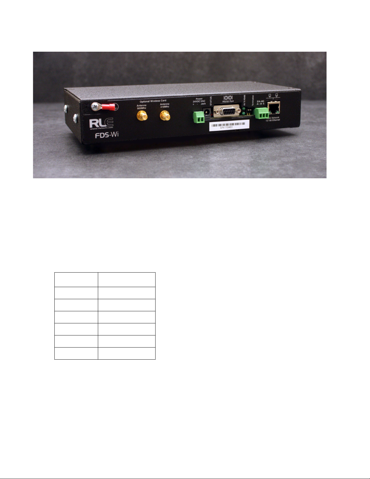
FDS-Wi
Wireless Gateway
User Guide
Version 2.5
Firmware Version 5.2.10
Page 2
Copyright and Trademark Notices
© Raymond & Lae Engineering, Inc. 2011. All rights reserved. RLE® is a registered trademark and
Seahawk™, Falcon™, and Raptor™ are trademarks of Raymond & Lae Engineering, Inc. The
products sold by Raymond & Lae Engineering, Inc. are subject to the limited warranty, limited liability,
and other terms and conditions of sale set forth at http://rletech.com/RLE-Terms-and-Conditions.html.
Revision History
Rev. No. Date
2.0 June 2010
2.1 September 2010
2.2 November 2010
2.3 March 2011
2.4 October 2011
2.5 May 2012
Note: As necessary, blank pages are added to make the page count even.
rletech.com 2 970.484.6510
Page 3

Product Registration
Product registration helps RLE Technologies inform owners of:
• Product upgrades
• Firmware enhancements
• New products and technologies
• Special offers available only to registered users
Any information provided to RLE Technologies through the registration form will be regarded as
confidential. RLE will not sell or distribute any of the information to third parties. To read our Privacy
Policy and registre your product, please visit our website: rletech.com.
Technical Support
Personal assistance is available Monday through Friday, from 8:00 a.m. to 5:00 p.m. MST.
A request for assistance may be sent to support@rletech.com.
Otherwise, please call us directly at: 800.518.1519.
The following information is located on the bottom of each Wireless Gateway unit. Please have this
information available whenever a technical support call is placed:
Product Model Number
Product Serial Number
Product Manufacture Date
970.484.6510 3 rletech.com
Page 4

RLE Product Warranty
Seller warrants to the Ultimate Purchaser (the purchaser who buys for use and not for resale) that all
products furnished under this order and which are manufactured by Seller will conform to final
specifications, drawings, samples and other written descriptions approved in writing by Seller, and will be
free from defects in materials and workmanship. These warranties shall remain in effect for a period of
twelve (12) months after shipment. If the Seller installs the equipment or supplies technical direction of
installation by contract, said one year shall run from the completion of installation, provided installation is not
unreasonably delayed by Ultimate Purchaser. Parts replaced or repaired in the warranty period shall carry
the unexpired portion of the original warranty. A unit placed with the purchaser on consignment and then
later purchased will be warranted for twelve (12) months from the time the Seller receives notification of the
Purchaser's intent to purchase said consigned item. The foregoing is in its entirety is subject to the provision
that in no case will the total warranty period extend beyond 18 months from date Seller ships equipment
from point of manufacture.
Products are NOT life and safety certified. In no event shall the Seller be liable for loss, damage, or expense
directly or indirectly arising from the use of the units, or from any other cause, except as expressly stated in
this warranty. Seller makes no warranties, express or implied, including any warranty as to merchantability
or fitness for a particular purpose or use. Seller is not liable for and Purchaser waives any right of action it
has or may have against Seller for any consequential or special damages arising out of any breach of
warranty, and for any damages Purchaser may claim for damage to any property or injury or death to any
person arising out of its purchase or the use, operation, or maintenance of the product. Seller will not be
liable for any labor subcontracted or performed by Purchaser for preparation of warranted item for return to
Seller's factory or for preparation work for field repair or replacement. Invoicing of Seller for labor either
performed or subcontracted by Purchaser will not be considered as a liability by the Seller.
The liability of Seller hereunder is limited to replacing or repairing at Seller's factory or on the job site at
Seller's option, any part or parts which have been returned to the Seller and which are defective or do not
conform to such specifications, drawings or other written descriptions; provided that such part or parts are
returned by the Ultimate Purchaser within ninety (90) days after such defect is discovered. The Seller shall
have the sole right to determine if the parts are to be repaired at the job site or whether they are to be
returned to the factory for repair or replacement. All items returned to Seller for repair or replacement must
be sent freight, prepaid to its factory. Purchaser must obtain Seller's Return Goods Authorization prior to
returning items. The above conditions must be met if warranty is to be valid. Seller will not be liable for any
damage done by unauthorized repair work, unauthorized replacement parts, from any misapplication of the
item, or for damage due to accident, abuse, or act of God.
This warranty shall be exclusive of any and all other warranties express or implied and may be modified only
by writing signed by any officer of the Seller. This warranty shall extend to the Ultimate Purchaser but to no
one else. Accessories supplied by Seller but manufactured by others carry any warranty the manufacturers
have made to Seller and which can be passed on to the Ultimate Purchaser.
Seller makes no warranty with respect to whether the products sold hereunder infringe any patent, U.S. or
foreign, and Purchaser represents that any specially ordered products do not infringe any patent. Purchaser
agrees to indemnify and hold Seller harmless from any liability by virtue of any patent claims where
Purchaser has ordered a product conforming to Purchaser's specifications, or conforming to Purchaser's
specific design.
Purchaser has not relied and shall not rely on any oral representation regarding the Product sold hereunder
and any oral representation shall not bind Seller and shall not be part of any warranty.
rletech.com 4 970.484.6510
Page 5

Contents
1 System Overview . . . . . . . . . . . . . . . . . . . . . . . . . . . . . . . . . . . . . . . . . . . . . . . . . . .11
Product Description. . . . . . . . . . . . . . . . . . . . . . . . . . . . . . . . . . . . . . . . . . . . . . . . . . . . . . . . . . . . . . . . 11
Rear Panel Indicators . . . . . . . . . . . . . . . . . . . . . . . . . . . . . . . . . . . . . . . . . . . . . . . . . . . . . . . . . . . . . . 11
Terminal Block Designations. . . . . . . . . . . . . . . . . . . . . . . . . . . . . . . . . . . . . . . . . . . . . . . . . . . . . . . . . 12
SW1 Switch Settings. . . . . . . . . . . . . . . . . . . . . . . . . . . . . . . . . . . . . . . . . . . . . . . . . . . . . . . . . . . . . . . 12
2 Getting Started . . . . . . . . . . . . . . . . . . . . . . . . . . . . . . . . . . . . . . . . . . . . . . . . . . . . .13
Installation . . . . . . . . . . . . . . . . . . . . . . . . . . . . . . . . . . . . . . . . . . . . . . . . . . . . . . . . . . . . . . . . . . . . . . . 13
Wiring . . . . . . . . . . . . . . . . . . . . . . . . . . . . . . . . . . . . . . . . . . . . . . . . . . . . . . . . . . . . . . . . . . . . . . . . . . 13
Power Supply and Ground Connections . . . . . . . . . . . . . . . . . . . . . . . . . . . . . . . . . . . . . . . . . . . 13
Connectivity. . . . . . . . . . . . . . . . . . . . . . . . . . . . . . . . . . . . . . . . . . . . . . . . . . . . . . . . . . . . . . . . . . . . . . 14
RJ45 Ethernet Connection . . . . . . . . . . . . . . . . . . . . . . . . . . . . . . . . . . . . . . . . . . . . . . . . . . . . . . 14
EIA-232 COM Connection . . . . . . . . . . . . . . . . . . . . . . . . . . . . . . . . . . . . . . . . . . . . . . . . . . . . . . 15
Modbus EIA-485 Connections . . . . . . . . . . . . . . . . . . . . . . . . . . . . . . . . . . . . . . . . . . . . . . . . . . . 16
Communication: Set the IP Address . . . . . . . . . . . . . . . . . . . . . . . . . . . . . . . . . . . . . . . . . . . . . . . . . . . 17
Set the IP Address Using a Web Browser . . . . . . . . . . . . . . . . . . . . . . . . . . . . . . . . . . . . . . . . . . 17
Set the Wireless Gateway IP Address using an EIA-232 Connection . . . . . . . . . . . . . . . . . . . . . 18
Sensor Discovery . . . . . . . . . . . . . . . . . . . . . . . . . . . . . . . . . . . . . . . . . . . . . . . . . . . . . . . . . . . . . . . . . 19
Sensor Mounting Tips . . . . . . . . . . . . . . . . . . . . . . . . . . . . . . . . . . . . . . . . . . . . . . . . . . . . . . . . . . . . . . 21
3 Web Interface – Standard Version. . . . . . . . . . . . . . . . . . . . . . . . . . . . . . . . . . . . . . 23
The Dashboard . . . . . . . . . . . . . . . . . . . . . . . . . . . . . . . . . . . . . . . . . . . . . . . . . . . . . . . . . . . . . . . . . . . 23
Sensor Summary Page . . . . . . . . . . . . . . . . . . . . . . . . . . . . . . . . . . . . . . . . . . . . . . . . . . . . . . . . . . . . . 24
Alarms and Warnings Page . . . . . . . . . . . . . . . . . . . . . . . . . . . . . . . . . . . . . . . . . . . . . . . . . . . . . . . . . 25
Configuration Page - FDS-Wi Tab . . . . . . . . . . . . . . . . . . . . . . . . . . . . . . . . . . . . . . . . . . . . . . . . . . . . 26
System Info . . . . . . . . . . . . . . . . . . . . . . . . . . . . . . . . . . . . . . . . . . . . . . . . . . . . . . . . . . . . . . . . . 27
System ID. . . . . . . . . . . . . . . . . . . . . . . . . . . . . . . . . . . . . . . . . . . . . . . . . . . . . . . . . . . . . . . . . . . 27
Network and Web. . . . . . . . . . . . . . . . . . . . . . . . . . . . . . . . . . . . . . . . . . . . . . . . . . . . . . . . . . . . . 27
Date . . . . . . . . . . . . . . . . . . . . . . . . . . . . . . . . . . . . . . . . . . . . . . . . . . . . . . . . . . . . . . . . . . . . . . . 29
Alarm Options . . . . . . . . . . . . . . . . . . . . . . . . . . . . . . . . . . . . . . . . . . . . . . . . . . . . . . . . . . . . . . . 29
Wireless . . . . . . . . . . . . . . . . . . . . . . . . . . . . . . . . . . . . . . . . . . . . . . . . . . . . . . . . . . . . . . . . . . . . 30
Graph/Log . . . . . . . . . . . . . . . . . . . . . . . . . . . . . . . . . . . . . . . . . . . . . . . . . . . . . . . . . . . . . . . . . . 31
Dashboard Key Sensors . . . . . . . . . . . . . . . . . . . . . . . . . . . . . . . . . . . . . . . . . . . . . . . . . . . . . . . 31
Dashboard Options . . . . . . . . . . . . . . . . . . . . . . . . . . . . . . . . . . . . . . . . . . . . . . . . . . . . . . . . . . . 32
Ethernet Packet Repeat . . . . . . . . . . . . . . . . . . . . . . . . . . . . . . . . . . . . . . . . . . . . . . . . . . . . . . . . 32
Configuration Page - Integration Tab . . . . . . . . . . . . . . . . . . . . . . . . . . . . . . . . . . . . . . . . . . . . . . . . . . 33
EIA-485 . . . . . . . . . . . . . . . . . . . . . . . . . . . . . . . . . . . . . . . . . . . . . . . . . . . . . . . . . . . . . . . . . . . . 33
BACnet/IP . . . . . . . . . . . . . . . . . . . . . . . . . . . . . . . . . . . . . . . . . . . . . . . . . . . . . . . . . . . . . . . . . . 34
Modbus . . . . . . . . . . . . . . . . . . . . . . . . . . . . . . . . . . . . . . . . . . . . . . . . . . . . . . . . . . . . . . . . . . . . 35
SNMP. . . . . . . . . . . . . . . . . . . . . . . . . . . . . . . . . . . . . . . . . . . . . . . . . . . . . . . . . . . . . . . . . . . . . . 35
Configuration Page - Sensors Tab . . . . . . . . . . . . . . . . . . . . . . . . . . . . . . . . . . . . . . . . . . . . . . . . . . . . 36
Configuration Page - Email Tab . . . . . . . . . . . . . . . . . . . . . . . . . . . . . . . . . . . . . . . . . . . . . . . . . . . . . . 40
Configuration Page - System Control Tab . . . . . . . . . . . . . . . . . . . . . . . . . . . . . . . . . . . . . . . . . . . . . . 41
Exit to Bootloader Button . . . . . . . . . . . . . . . . . . . . . . . . . . . . . . . . . . . . . . . . . . . . . . . . . . . . . 41
Delete All Sensors Button . . . . . . . . . . . . . . . . . . . . . . . . . . . . . . . . . . . . . . . . . . . . . . . . . . . . . 42
Clear All Alarms Button. . . . . . . . . . . . . . . . . . . . . . . . . . . . . . . . . . . . . . . . . . . . . . . . . . . . . . . 42
Clear All Log Data Button . . . . . . . . . . . . . . . . . . . . . . . . . . . . . . . . . . . . . . . . . . . . . . . . . . . . . 42
rletech.com 5 970.484.6510
Page 6

Download Configuration File Link . . . . . . . . . . . . . . . . . . . . . . . . . . . . . . . . . . . . . . . . . . . . . . 42
Download Sensor CSV File Link . . . . . . . . . . . . . . . . . . . . . . . . . . . . . . . . . . . . . . . . . . . . . . . . 42
Configuration/Flash Upload . . . . . . . . . . . . . . . . . . . . . . . . . . . . . . . . . . . . . . . . . . . . . . . . . . . 43
Refresh Link. . . . . . . . . . . . . . . . . . . . . . . . . . . . . . . . . . . . . . . . . . . . . . . . . . . . . . . . . . . . . . . . . . . . . . 43
4 Web Interface – Integration Version . . . . . . . . . . . . . . . . . . . . . . . . . . . . . . . . . . . . 45
The Homepage . . . . . . . . . . . . . . . . . . . . . . . . . . . . . . . . . . . . . . . . . . . . . . . . . . . . . . . . . . . . . . . . . . . 46
View All Sensor IDs . . . . . . . . . . . . . . . . . . . . . . . . . . . . . . . . . . . . . . . . . . . . . . . . . . . . . . . . . . . 47
Individual Sensor Configuration . . . . . . . . . . . . . . . . . . . . . . . . . . . . . . . . . . . . . . . . . . . . . . . . . . 47
Configuration Page . . . . . . . . . . . . . . . . . . . . . . . . . . . . . . . . . . . . . . . . . . . . . . . . . . . . . . . . . . . . . . . . 52
Wireless . . . . . . . . . . . . . . . . . . . . . . . . . . . . . . . . . . . . . . . . . . . . . . . . . . . . . . . . . . . . . . . . . . . . 53
Network and Web . . . . . . . . . . . . . . . . . . . . . . . . . . . . . . . . . . . . . . . . . . . . . . . . . . . . . . . . . . . . . 54
Date . . . . . . . . . . . . . . . . . . . . . . . . . . . . . . . . . . . . . . . . . . . . . . . . . . . . . . . . . . . . . . . . . . . . . . . 55
System Info. . . . . . . . . . . . . . . . . . . . . . . . . . . . . . . . . . . . . . . . . . . . . . . . . . . . . . . . . . . . . . . . . . 56
EIA-485. . . . . . . . . . . . . . . . . . . . . . . . . . . . . . . . . . . . . . . . . . . . . . . . . . . . . . . . . . . . . . . . . . . . . 56
BACNet. . . . . . . . . . . . . . . . . . . . . . . . . . . . . . . . . . . . . . . . . . . . . . . . . . . . . . . . . . . . . . . . . . . . . 57
Modbus. . . . . . . . . . . . . . . . . . . . . . . . . . . . . . . . . . . . . . . . . . . . . . . . . . . . . . . . . . . . . . . . . . . . . 57
Sensor Logging . . . . . . . . . . . . . . . . . . . . . . . . . . . . . . . . . . . . . . . . . . . . . . . . . . . . . . . . . . . . . . 58
Configuration Upload/Download. . . . . . . . . . . . . . . . . . . . . . . . . . . . . . . . . . . . . . . . . . . . . . . . . . 58
System Control . . . . . . . . . . . . . . . . . . . . . . . . . . . . . . . . . . . . . . . . . . . . . . . . . . . . . . . . . . . . . . . 59
Configuration SNMP/SMTP Page . . . . . . . . . . . . . . . . . . . . . . . . . . . . . . . . . . . . . . . . . . . . . . . . . . . . . 60
Refresh Link. . . . . . . . . . . . . . . . . . . . . . . . . . . . . . . . . . . . . . . . . . . . . . . . . . . . . . . . . . . . . . . . . . . . . . 61
5 Update Firmware . . . . . . . . . . . . . . . . . . . . . . . . . . . . . . . . . . . . . . . . . . . . . . . . . . . 63
Load the Application Firmware Using MIME . . . . . . . . . . . . . . . . . . . . . . . . . . . . . . . . . . . . . . . . . . . . . 63
Load the Flash Firmware Using TFTP. . . . . . . . . . . . . . . . . . . . . . . . . . . . . . . . . . . . . . . . . . . . . . . . . . 64
A Modbus Communications . . . . . . . . . . . . . . . . . . . . . . . . . . . . . . . . . . . . . . . . . . . . 65
Implementation Basics. . . . . . . . . . . . . . . . . . . . . . . . . . . . . . . . . . . . . . . . . . . . . . . . . . . . . . . . . . . . . . 65
Modes of Transmission . . . . . . . . . . . . . . . . . . . . . . . . . . . . . . . . . . . . . . . . . . . . . . . . . . . . . . . . 65
Slave Address Field . . . . . . . . . . . . . . . . . . . . . . . . . . . . . . . . . . . . . . . . . . . . . . . . . . . . . . . . 65
Function Field. . . . . . . . . . . . . . . . . . . . . . . . . . . . . . . . . . . . . . . . . . . . . . . . . . . . . . . . . . . . . 65
Data Field. . . . . . . . . . . . . . . . . . . . . . . . . . . . . . . . . . . . . . . . . . . . . . . . . . . . . . . . . . . . . . . . 66
Error Check (Checksum) Field. . . . . . . . . . . . . . . . . . . . . . . . . . . . . . . . . . . . . . . . . . . . . . . . 66
Exception Responses. . . . . . . . . . . . . . . . . . . . . . . . . . . . . . . . . . . . . . . . . . . . . . . . . . . . . . . . . . 66
Packet Communications for the Wireless Gateway . . . . . . . . . . . . . . . . . . . . . . . . . . . . . . . . . . . . . . . . 66
Function 03: Read Output Registers . . . . . . . . . . . . . . . . . . . . . . . . . . . . . . . . . . . . . . . . . . . . . . 66
RTU Framing . . . . . . . . . . . . . . . . . . . . . . . . . . . . . . . . . . . . . . . . . . . . . . . . . . . . . . . . . . . . . . . . . . . . . 67
B Troubleshooting . . . . . . . . . . . . . . . . . . . . . . . . . . . . . . . . . . . . . . . . . . . . . . . . . . . . 69
C Technical Specifications . . . . . . . . . . . . . . . . . . . . . . . . . . . . . . . . . . . . . . . . . . . . . 73
970.484.6510 6 rletech.com
Page 7

Figures
1 System Overview . . . . . . . . . . . . . . . . . . . . . . . . . . . . . . . . . . . . . . . . . . . . . . . . . . .11
Figure 1.1 Terminal Block Locations. . . . . . . . . . . . . . . . . . . . . . . . . . . . . . . . . . . . . . . . . . . . . . . . 12
2 Getting Started . . . . . . . . . . . . . . . . . . . . . . . . . . . . . . . . . . . . . . . . . . . . . . . . . . . . .13
Figure 2.1 24VDC Power Supply Connection. . . . . . . . . . . . . . . . . . . . . . . . . . . . . . . . . . . . . . . . . 14
Figure 2.2 Wireless Gateway Antennae . . . . . . . . . . . . . . . . . . . . . . . . . . . . . . . . . . . . . . . . . . . . . 14
Figure 2.3 Ethernet Connection to a PC Using a Crossover Cable . . . . . . . . . . . . . . . . . . . . . . . . 15
Figure 2.4 Ethernet Connection to a PC on a Subnet, Using a Hub/Switch and CAT5 Cables . . . 15
Figure 2.5 EIA-232 COM Connection . . . . . . . . . . . . . . . . . . . . . . . . . . . . . . . . . . . . . . . . . . . . . . . 15
Figure 2.6 EIA-485 Connection. . . . . . . . . . . . . . . . . . . . . . . . . . . . . . . . . . . . . . . . . . . . . . . . . . . . 16
Figure 2.7 Enabling Sensor Discovery . . . . . . . . . . . . . . . . . . . . . . . . . . . . . . . . . . . . . . . . . . . . . . 19
Figure 2.8 Remove the Sensors’s Lid. . . . . . . . . . . . . . . . . . . . . . . . . . . . . . . . . . . . . . . . . . . . . . . 19
Figure 2.9 Remove the Battery’s Protective Tab . . . . . . . . . . . . . . . . . . . . . . . . . . . . . . . . . . . . . . 19
Figure 2.10 Sensor’s Serial Number on Product Label. . . . . . . . . . . . . . . . . . . . . . . . . . . . . . . . . . . 20
Figure 2.11 Verifying a Sensor’s Discovery . . . . . . . . . . . . . . . . . . . . . . . . . . . . . . . . . . . . . . . . . . . 20
Figure 2.12 Label the Sensor . . . . . . . . . . . . . . . . . . . . . . . . . . . . . . . . . . . . . . . . . . . . . . . . . . . . . . 20
Figure 2.13 Magnetic Strips Used to Mount a Sensor . . . . . . . . . . . . . . . . . . . . . . . . . . . . . . . . . . . 21
Figure 2.14 Recommended Length of 0.5 Inch for Magnetic Strip . . . . . . . . . . . . . . . . . . . . . . . . . . 21
3 Web Interface – Standard Version . . . . . . . . . . . . . . . . . . . . . . . . . . . . . . . . . . . . . 23
Figure 3.1 Wireless Gateway Dashboard . . . . . . . . . . . . . . . . . . . . . . . . . . . . . . . . . . . . . . . . . . . . 23
Figure 3.2 Sensor Summary Sample Menu . . . . . . . . . . . . . . . . . . . . . . . . . . . . . . . . . . . . . . . . . . 24
Figure 3.3 Current Log Graphs and Log Archive . . . . . . . . . . . . . . . . . . . . . . . . . . . . . . . . . . . . . . 25
Figure 3.4 Alarm and Warnings Page. . . . . . . . . . . . . . . . . . . . . . . . . . . . . . . . . . . . . . . . . . . . . . . 25
Figure 3.5 Configuration Page . . . . . . . . . . . . . . . . . . . . . . . . . . . . . . . . . . . . . . . . . . . . . . . . . . . . 26
Figure 3.6 System Info Section. . . . . . . . . . . . . . . . . . . . . . . . . . . . . . . . . . . . . . . . . . . . . . . . . . . . 27
Figure 3.7 System ID Section . . . . . . . . . . . . . . . . . . . . . . . . . . . . . . . . . . . . . . . . . . . . . . . . . . . . . 27
Figure 3.8 Network and Web Section . . . . . . . . . . . . . . . . . . . . . . . . . . . . . . . . . . . . . . . . . . . . . . . 27
Figure 3.9 Date Section . . . . . . . . . . . . . . . . . . . . . . . . . . . . . . . . . . . . . . . . . . . . . . . . . . . . . . . . . 29
Figure 3.10 Alarm Options Section . . . . . . . . . . . . . . . . . . . . . . . . . . . . . . . . . . . . . . . . . . . . . . . . . . 29
Figure 3.11 Wireless Section . . . . . . . . . . . . . . . . . . . . . . . . . . . . . . . . . . . . . . . . . . . . . . . . . . . . . . 30
Figure 3.12 Graph/Log Section. . . . . . . . . . . . . . . . . . . . . . . . . . . . . . . . . . . . . . . . . . . . . . . . . . . . . 31
Figure 3.13 Dashboard Key Sensors Section. . . . . . . . . . . . . . . . . . . . . . . . . . . . . . . . . . . . . . . . . . 31
Figure 3.14 Dashboard Options Section. . . . . . . . . . . . . . . . . . . . . . . . . . . . . . . . . . . . . . . . . . . . . . 32
Figure 3.15 Ethernet Packet Repeat Section . . . . . . . . . . . . . . . . . . . . . . . . . . . . . . . . . . . . . . . . . . 32
Figure 3.16 Configuration Page, Integration Tab . . . . . . . . . . . . . . . . . . . . . . . . . . . . . . . . . . . . . . . 33
Figure 3.17 EIA-485 Section. . . . . . . . . . . . . . . . . . . . . . . . . . . . . . . . . . . . . . . . . . . . . . . . . . . . . . . 33
Figure 3.18 BACnet Section . . . . . . . . . . . . . . . . . . . . . . . . . . . . . . . . . . . . . . . . . . . . . . . . . . . . . . . 34
Figure 3.19 General BACnet Capabilities of the Device . . . . . . . . . . . . . . . . . . . . . . . . . . . . . . . . . . 35
Figure 3.20 Modbus Section . . . . . . . . . . . . . . . . . . . . . . . . . . . . . . . . . . . . . . . . . . . . . . . . . . . . . . . 35
Figure 3.21 SNMP Section . . . . . . . . . . . . . . . . . . . . . . . . . . . . . . . . . . . . . . . . . . . . . . . . . . . . . . . . 36
Figure 3.22 Sensors Tab. . . . . . . . . . . . . . . . . . . . . . . . . . . . . . . . . . . . . . . . . . . . . . . . . . . . . . . . . . 37
Figure 3.23 Email Tab. . . . . . . . . . . . . . . . . . . . . . . . . . . . . . . . . . . . . . . . . . . . . . . . . . . . . . . . . . . . 40
Figure 3.24 System Control Tab . . . . . . . . . . . . . . . . . . . . . . . . . . . . . . . . . . . . . . . . . . . . . . . . . . . . 41
Figure 3.25 Exit to Bootloader Message. . . . . . . . . . . . . . . . . . . . . . . . . . . . . . . . . . . . . . . . . . . . . . 41
Figure 3.26 Delete All Sensors Message . . . . . . . . . . . . . . . . . . . . . . . . . . . . . . . . . . . . . . . . . . . . . 42
Figure 3.27 Clear All Alarms Message . . . . . . . . . . . . . . . . . . . . . . . . . . . . . . . . . . . . . . . . . . . . . . . 42
rletech.com 7 970.484.6510
Page 8

Figure 3.28 Clear All Log Data Message. . . . . . . . . . . . . . . . . . . . . . . . . . . . . . . . . . . . . . . . . . . . . . 42
Figure 3.29 Download Configuration File Message. . . . . . . . . . . . . . . . . . . . . . . . . . . . . . . . . . . . . . 42
Figure 3.30 Download Sensor CSV File Message . . . . . . . . . . . . . . . . . . . . . . . . . . . . . . . . . . . . . . 42
Figure 3.31 Upload Message . . . . . . . . . . . . . . . . . . . . . . . . . . . . . . . . . . . . . . . . . . . . . . . . . . . . . . 43
4 Web Interface – Integration Version . . . . . . . . . . . . . . . . . . . . . . . . . . . . . . . . . . . 45
Figure 4.1 Logo Configuration Page (For Displaying “Classic” View) . . . . . . . . . . . . . . . . . . . . . . . 45
Figure 4.2 Wireless Gateway Homepage . . . . . . . . . . . . . . . . . . . . . . . . . . . . . . . . . . . . . . . . . . . . 46
Figure 4.3 View All Sensors Page . . . . . . . . . . . . . . . . . . . . . . . . . . . . . . . . . . . . . . . . . . . . . . . . . 47
Figure 4.4 Editing Sensor Properties . . . . . . . . . . . . . . . . . . . . . . . . . . . . . . . . . . . . . . . . . . . . . . . 48
Figure 4.5 Wireless Sensor Configuration . . . . . . . . . . . . . . . . . . . . . . . . . . . . . . . . . . . . . . . . . . . 48
Figure 4.6 Configuration Page . . . . . . . . . . . . . . . . . . . . . . . . . . . . . . . . . . . . . . . . . . . . . . . . . . . . 52
Figure 4.7 Wireless Section . . . . . . . . . . . . . . . . . . . . . . . . . . . . . . . . . . . . . . . . . . . . . . . . . . . . . . 53
Figure 4.8 Network and Web Section . . . . . . . . . . . . . . . . . . . . . . . . . . . . . . . . . . . . . . . . . . . . . . . 54
Figure 4.9 Date Section . . . . . . . . . . . . . . . . . . . . . . . . . . . . . . . . . . . . . . . . . . . . . . . . . . . . . . . . . 55
Figure 4.10 System Info Section . . . . . . . . . . . . . . . . . . . . . . . . . . . . . . . . . . . . . . . . . . . . . . . . . . . 56
Figure 4.11 EIA-485 Section . . . . . . . . . . . . . . . . . . . . . . . . . . . . . . . . . . . . . . . . . . . . . . . . . . . . . . 56
Figure 4.12 BACNet Section . . . . . . . . . . . . . . . . . . . . . . . . . . . . . . . . . . . . . . . . . . . . . . . . . . . . . . 57
Figure 4.13 Modbus Section . . . . . . . . . . . . . . . . . . . . . . . . . . . . . . . . . . . . . . . . . . . . . . . . . . . . . . . 57
Figure 4.14 Sensor Logging Section . . . . . . . . . . . . . . . . . . . . . . . . . . . . . . . . . . . . . . . . . . . . . . . . . 58
Figure 4.15 Configuration Upload/Download Section . . . . . . . . . . . . . . . . . . . . . . . . . . . . . . . . . . . . 58
Figure 4.16 Download Configuration File . . . . . . . . . . . . . . . . . . . . . . . . . . . . . . . . . . . . . . . . . . . . . 58
Figure 4.17 Download Sensor CSV File . . . . . . . . . . . . . . . . . . . . . . . . . . . . . . . . . . . . . . . . . . . . . . 59
Figure 4.18 System Control . . . . . . . . . . . . . . . . . . . . . . . . . . . . . . . . . . . . . . . . . . . . . . . . . . . . . . . 59
Figure 4.19 Exit to Bootloader . . . . . . . . . . . . . . . . . . . . . . . . . . . . . . . . . . . . . . . . . . . . . . . . . . . . . 59
Figure 4.20 Delete All Sensors . . . . . . . . . . . . . . . . . . . . . . . . . . . . . . . . . . . . . . . . . . . . . . . . . . . . . 59
Figure 4.21 SMTP Configuration Section . . . . . . . . . . . . . . . . . . . . . . . . . . . . . . . . . . . . . . . . . . . . . 60
Figure 4.22 SNMP Configuration Section . . . . . . . . . . . . . . . . . . . . . . . . . . . . . . . . . . . . . . . . . . . . . 61
5 Update Firmware . . . . . . . . . . . . . . . . . . . . . . . . . . . . . . . . . . . . . . . . . . . . . . . . . . . 63
Figure 5.1 MIME Sample. . . . . . . . . . . . . . . . . . . . . . . . . . . . . . . . . . . . . . . . . . . . . . . . . . . . . . . . . 63
A Modbus Communications . . . . . . . . . . . . . . . . . . . . . . . . . . . . . . . . . . . . . . . . . . . . 65
B Troubleshooting . . . . . . . . . . . . . . . . . . . . . . . . . . . . . . . . . . . . . . . . . . . . . . . . . . . 69
C Technical Specifications . . . . . . . . . . . . . . . . . . . . . . . . . . . . . . . . . . . . . . . . . . . . . 73
970.484.6510 8 rletech.com
Page 9

Tables
1 System Overview . . . . . . . . . . . . . . . . . . . . . . . . . . . . . . . . . . . . . . . . . . . . . . . . . . 11
Table 1.1 EIA-485 TX and EIA-485-RX . . . . . . . . . . . . . . . . . . . . . . . . . . . . . . . . . . . . . . . . . . . . . 11
Table 1.2 Terminal Block Designations . . . . . . . . . . . . . . . . . . . . . . . . . . . . . . . . . . . . . . . . . . . . . 12
Table 1.3 SW1 Switch Settings . . . . . . . . . . . . . . . . . . . . . . . . . . . . . . . . . . . . . . . . . . . . . . . . . . . 12
2 Getting Started . . . . . . . . . . . . . . . . . . . . . . . . . . . . . . . . . . . . . . . . . . . . . . . . . . . . 13
3 Web Interface – Standard Version. . . . . . . . . . . . . . . . . . . . . . . . . . . . . . . . . . . . . 23
Table 3.1 Dashboard Alarm Color Codes . . . . . . . . . . . . . . . . . . . . . . . . . . . . . . . . . . . . . . . . . . . 24
Table 3.2 Sensor Summary Menu Options . . . . . . . . . . . . . . . . . . . . . . . . . . . . . . . . . . . . . . . . . . 24
Table 3.3 Network and Web Section Options . . . . . . . . . . . . . . . . . . . . . . . . . . . . . . . . . . . . . . . . 28
Table 3.4 Date Section Options. . . . . . . . . . . . . . . . . . . . . . . . . . . . . . . . . . . . . . . . . . . . . . . . . . . 29
Table 3.5 Alarm Section Option . . . . . . . . . . . . . . . . . . . . . . . . . . . . . . . . . . . . . . . . . . . . . . . . . . . 29
Table 3.6 Wireless Section Options. . . . . . . . . . . . . . . . . . . . . . . . . . . . . . . . . . . . . . . . . . . . . . . . 30
Table 3.7 Graph/Log Section Option . . . . . . . . . . . . . . . . . . . . . . . . . . . . . . . . . . . . . . . . . . . . . . . 31
Table 3.8 Dashboard Key Sensors Section Option . . . . . . . . . . . . . . . . . . . . . . . . . . . . . . . . . . . . 31
Table 3.9 Dashboard Option Section Options . . . . . . . . . . . . . . . . . . . . . . . . . . . . . . . . . . . . . . . . 32
Table 3.10 Ethernet Packet Repeat Section Options . . . . . . . . . . . . . . . . . . . . . . . . . . . . . . . . . . . 32
Table 3.11 EIA-485 Section Options . . . . . . . . . . . . . . . . . . . . . . . . . . . . . . . . . . . . . . . . . . . . . . . . 33
Table 3.12 BACnet Section Options . . . . . . . . . . . . . . . . . . . . . . . . . . . . . . . . . . . . . . . . . . . . . . . . 34
Table 3.13 Modbus Section Option . . . . . . . . . . . . . . . . . . . . . . . . . . . . . . . . . . . . . . . . . . . . . . . . . 35
Table 3.14 SNMP Section Options . . . . . . . . . . . . . . . . . . . . . . . . . . . . . . . . . . . . . . . . . . . . . . . . . 36
Table 3.15 Sensors Tab Configuration Options. . . . . . . . . . . . . . . . . . . . . . . . . . . . . . . . . . . . . . . . 38
Table 3.16 Sensors Tab Read-only Data. . . . . . . . . . . . . . . . . . . . . . . . . . . . . . . . . . . . . . . . . . . . . 39
Table 3.17 SMTP/Email Configuration Options . . . . . . . . . . . . . . . . . . . . . . . . . . . . . . . . . . . . . . . . 41
4 Web Interface – Integration Version . . . . . . . . . . . . . . . . . . . . . . . . . . . . . . . . . . . 45
Table 4.1 Color Codes for Homepage . . . . . . . . . . . . . . . . . . . . . . . . . . . . . . . . . . . . . . . . . . . . . . 46
Table 4.2 Wireless Sensor Configuration Options. . . . . . . . . . . . . . . . . . . . . . . . . . . . . . . . . . . . . 49
Table 4.3 Wireless Section Options. . . . . . . . . . . . . . . . . . . . . . . . . . . . . . . . . . . . . . . . . . . . . . . . 53
Table 4.4 Network and Web Section Options . . . . . . . . . . . . . . . . . . . . . . . . . . . . . . . . . . . . . . . . 54
Table 4.5 Date Section Options. . . . . . . . . . . . . . . . . . . . . . . . . . . . . . . . . . . . . . . . . . . . . . . . . . . 55
Table 4.6 EIA-485 Section. . . . . . . . . . . . . . . . . . . . . . . . . . . . . . . . . . . . . . . . . . . . . . . . . . . . . . . 56
Table 4.7 BACNet Section Options . . . . . . . . . . . . . . . . . . . . . . . . . . . . . . . . . . . . . . . . . . . . . . . . 57
Table 4.8 Modbus Section Option . . . . . . . . . . . . . . . . . . . . . . . . . . . . . . . . . . . . . . . . . . . . . . . . . 57
Table 4.9 Sensor Logging Section Option . . . . . . . . . . . . . . . . . . . . . . . . . . . . . . . . . . . . . . . . . . . 58
Table 4.10 SNMP Configuration Section Options . . . . . . . . . . . . . . . . . . . . . . . . . . . . . . . . . . . . . . 60
Table 4.11 SNMP Configuration Section Options . . . . . . . . . . . . . . . . . . . . . . . . . . . . . . . . . . . . . . 61
5 Update Firmware . . . . . . . . . . . . . . . . . . . . . . . . . . . . . . . . . . . . . . . . . . . . . . . . . . . 63
A Modbus Communications . . . . . . . . . . . . . . . . . . . . . . . . . . . . . . . . . . . . . . . . . . . 65
Table A.1 Exception Codes . . . . . . . . . . . . . . . . . . . . . . . . . . . . . . . . . . . . . . . . . . . . . . . . . . . . . . 66
Table A.2 Read Output Registers Packet Structure. . . . . . . . . . . . . . . . . . . . . . . . . . . . . . . . . . . . 66
Table A.3 Output Registers . . . . . . . . . . . . . . . . . . . . . . . . . . . . . . . . . . . . . . . . . . . . . . . . . . . . . . 67
Table A.4 Response Sample . . . . . . . . . . . . . . . . . . . . . . . . . . . . . . . . . . . . . . . . . . . . . . . . . . . . . 67
B Troubleshooting . . . . . . . . . . . . . . . . . . . . . . . . . . . . . . . . . . . . . . . . . . . . . . . . . . . 69
rletech.com 9 970.484.6510
Page 10

C Technical Specifications . . . . . . . . . . . . . . . . . . . . . . . . . . . . . . . . . . . . . . . . . . . . 73
Table C.1 Technical Specifications. . . . . . . . . . . . . . . . . . . . . . . . . . . . . . . . . . . . . . . . . . . . . . . . . 73
970.484.6510 10 rletech.com
Page 11
1.1. Product Description
The Wireless Gateway is a wireless acquisition appliance that helps monitor remote facilities.
The Wireless Gateway receives 418 and 900 MHZ signals from wireless devices and relays
them to facilities monitoring systems as SNMP, Modbus TCP/IP, Modbus RTU, BACnet/IP,
and BACnet MS/TP signals.
C HAPTER
CHAPTER 0SYSTEM OVERVIEW
The Wireless Gateway’s wireless sensors can receive signals from products providing dry
contact, analog (0-20mA), 0-5VDC, or 0-10VDC signals. Commonly used sensors include,
but are not limited to, temperature/humidity, temperature, door counters, thermistors, motion
sensors, power monitors, and more.
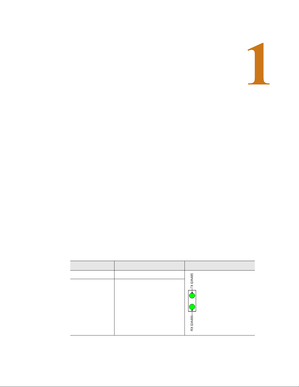
1.2. Rear Panel Indicators
The back of the Wireless Gateway has two status indicators to show when data is being
transmitted and when data is being received through the EIA-485 port. When data is either
being transmitted or received the status lights will blink. If no information is being
communicated, the lights are off.
Status Indicator Figure
EIA-485 TX Data is being transmitted.
EIA-485 RX Data is being received.
Table 1.1
www.rletech.com 11 970.484.6510
EIA-485 TX and EIA-485-RX
Page 12
1 System Overview
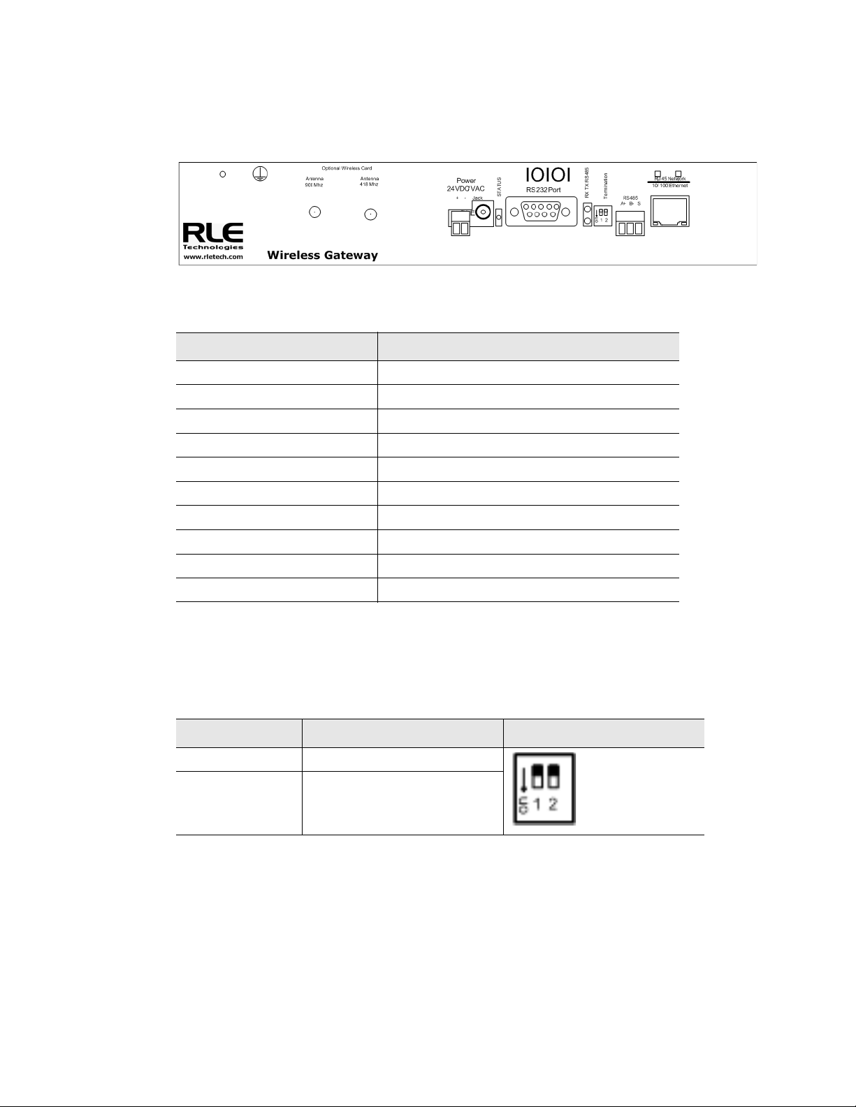
1.3. Terminal Block Designations
Figure 1.1
Item Description
Antenna 916 MHz RP-SMA connector
Antenna 418 MHz RP-SMA connector
Power 24 VDC/VAC Power terminal block
Jack Wall wart adapter connector
Status Status LED
RS232 Port DB9 female connector
RX TX RS485 LED Receive/Transmit status LED
RS485 Termination switch 1 (unused); 2 100 ohm termination
RS485 port EIA-485 circuit connector
RJ45 Ethernet port 10/100 BASE-T connector
Table 1.2
Terminal Block Locations
Terminal Block Designations
1.4. SW1 Switch Settings
Status Indicator Figure
SW1-1 Not used
SW1-2 EIA-485 Termination
(On=100 ohm termination)
Table 1.3
www.rletech.com 12 970.484.6510
SW1 Switch Settings
Page 13
2.1. Installation
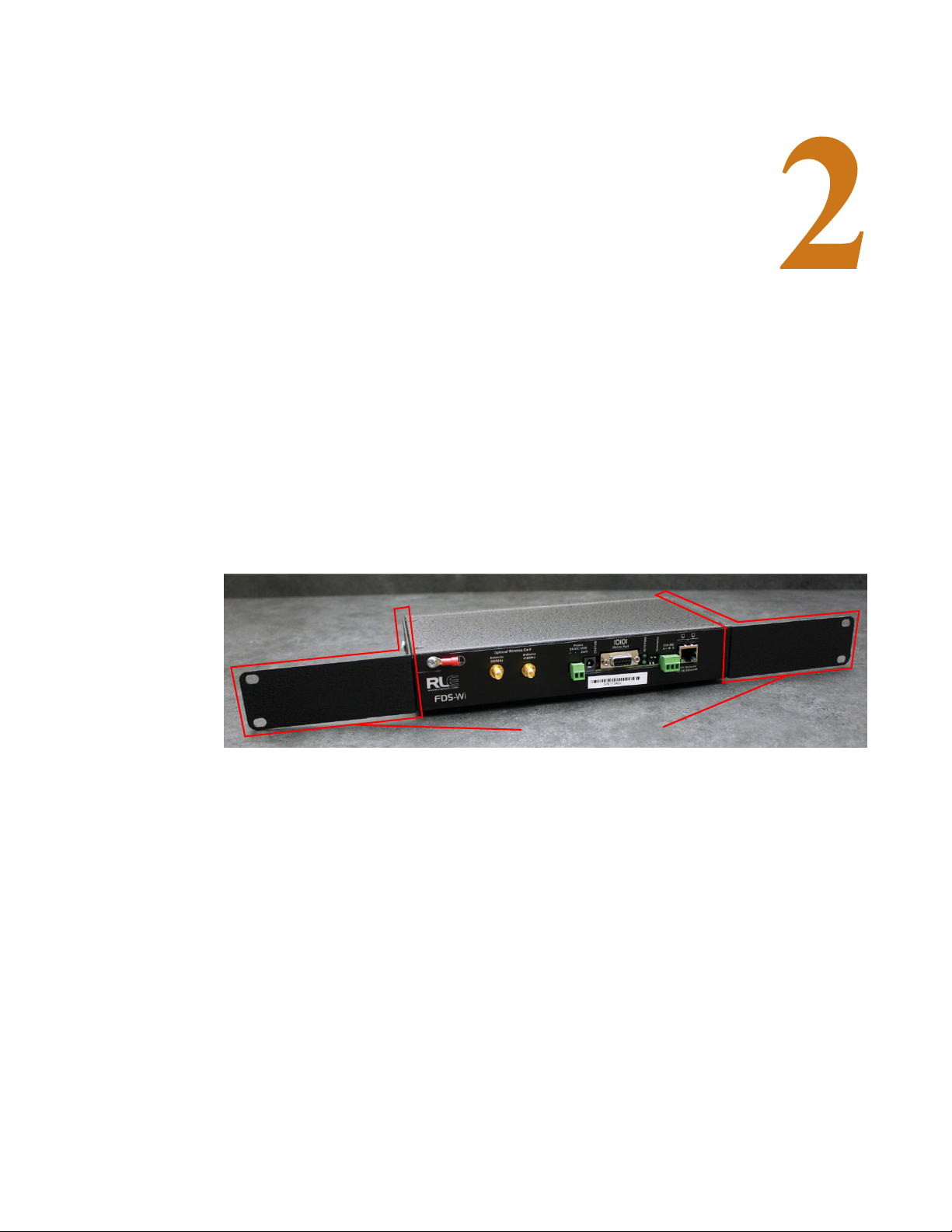
MOUNTING BRACKETS
The Wireless Gateway comes with two brackets that, when attached to the device, allow it to
be mounted in a 19-inch rack. Remove the screws from the side of the device, put the brackets
in place, and reapply the screws. Mount the device in a rack. Use the proper anchoring method
to mount the unit securely.
C HAPTER
CHAPTER 0GETTING STARTED
2.2. Wiring
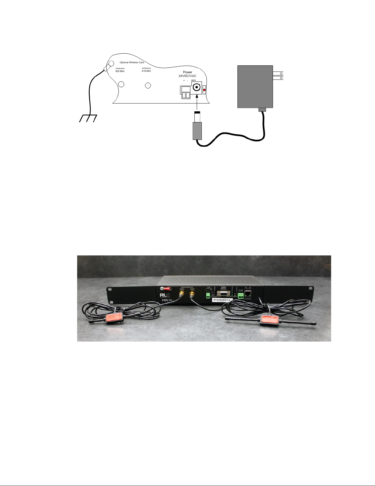
2.2.1 Power Supply and Ground Connections
RLE Technologies recommends powering the Wireless Gateway from a UPS supply so the
device can send alarm notifications during a power outage. Connect an 18AWG ground wire
from the ground terminal to a suitable earth ground. Plug the wall adapter into P1 and a UPS
outlet. The wall adapter has a five foot (1.524m) power cord.
Connect 24VDC to the unit through either the jack input or terminal block.
www.rletech.com 13 970.484.6510
Page 14
2 Getting Started
418 MHZ
900 MHZ
ANTENNA
ANTENNA
Figure 2.1
24VDC Power Supply Connection
If the EIA-485 port will be used for Modbus RTU communication, RLE Technologies
recommends an 18AWG shielded twisted pair stranded copper wire for the connection, using
no more than 2000 feet (609.6m) of wire at this specification. If longer runs are needed, please
contact RLE Technologies.
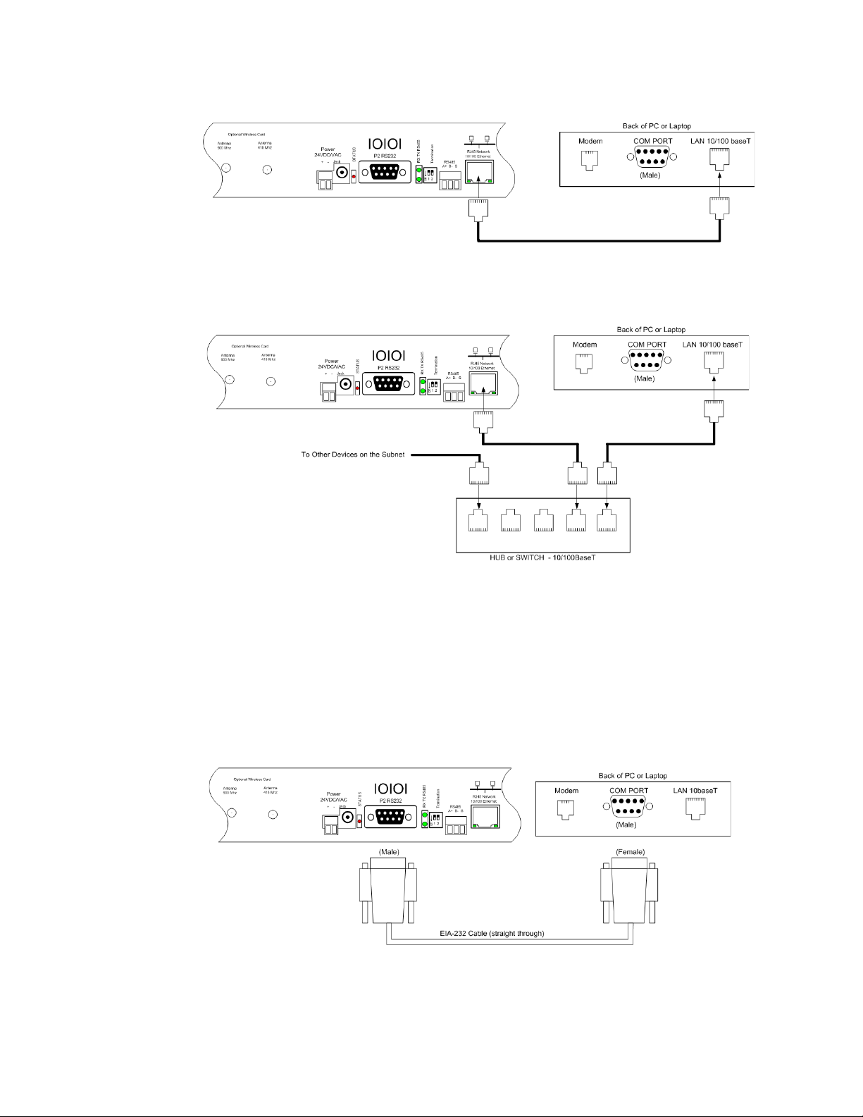
The Wireless Gateway is shipped with a 418 MHz, 6-foot cable antenna and a 916 MHz,
6-foot cable antenna. The 418 MHz antenna has longer shafts; the 900 MHz antenna has
shorter shafts. Plug each antenna into its appropriate jack on the front of the Wireless
Gateway.
Figure 2.2
Wireless Gateway Antennae
2.3. Connectivity
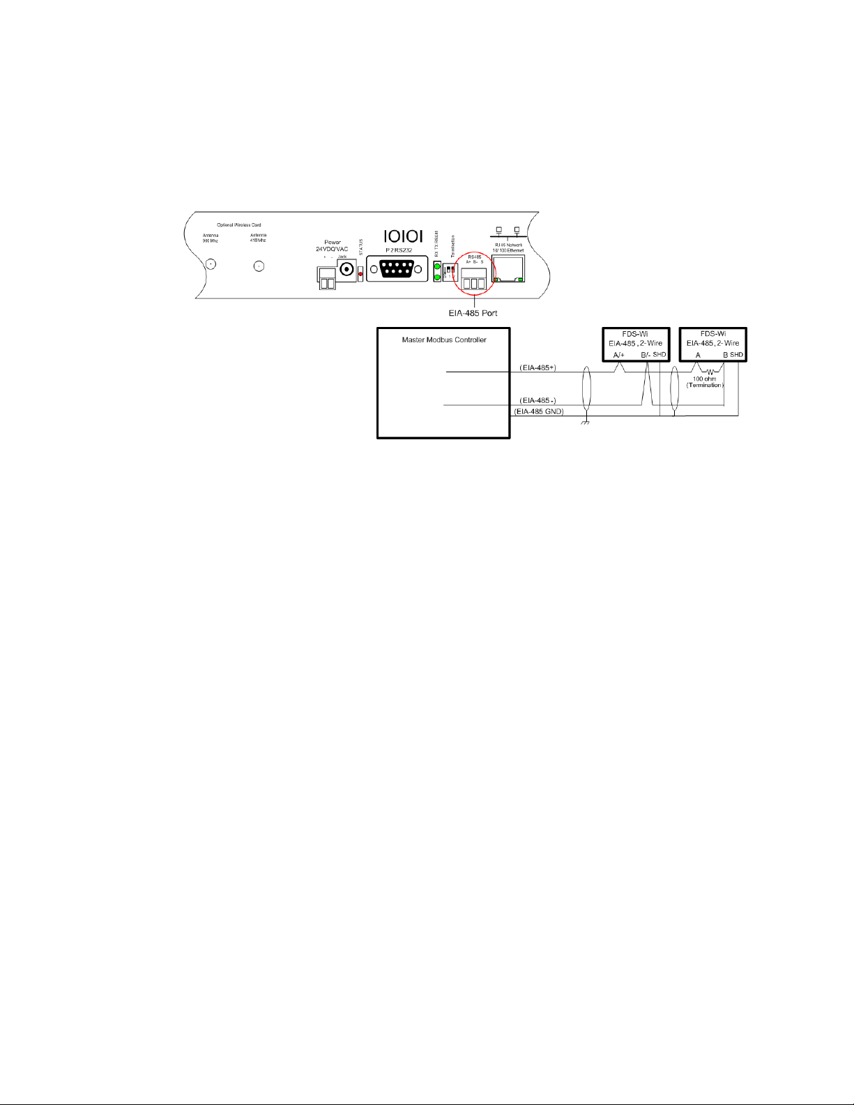
2.3.1 RJ45 Ethernet Connection
The Wireless Gateway has an internal 10/100BASE-T Ethernet port that is used for
configuration. The Ethernet port supports Web browser access, email (SMTP), BACnet slave,
Modbus slave, and SNMP. The device can connect directly to a PC with a crossover cable
(provided), or it can connect to a PC through a hub or switch, with CAT5 cables.
www.rletech.com 14 970.484.6510
Page 15
2 Getting Started
Figure 2.3
Figure 2.4
Ethernet Connection to a PC Using a Crossover Cable
Ethernet Connection to a PC on a Subnet, Using a Hub/Switch and CAT5 Cables
2.3.2 EIA-232 COM Connection
The Wireless Gateway can be connected directly to a PC through its EIA-232 port. This is
useful for IP configuration, firmware downloads, and troubleshooting. The EIA-232
connection is only used as a temporary connection. Connect the straight through, 9-pin serial
cable as shown in Figure 2.5.
Figure 2.5
www.rletech.com 15 970.484.6510
EIA-232 COM Connection
Page 16
2 Getting Started
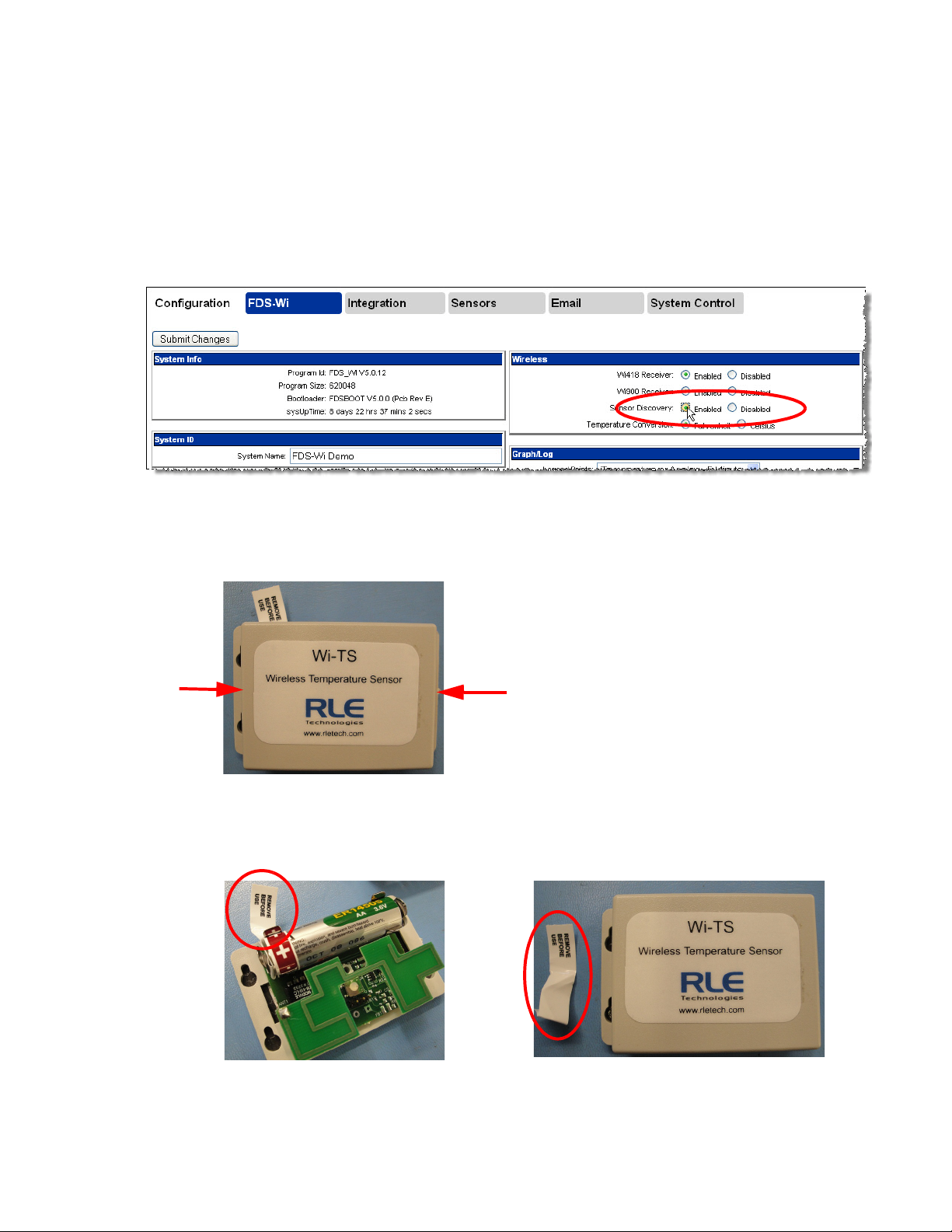
2.3.3 Modbus EIA-485 Connections
The Wireless Gateway can function as a Modbus Slave over an EIA-485, 2-wire hardware
connection, as shown in Figure 2.6.
Figure 2.6
EIA-485 Connection
www.rletech.com 16 970.484.6510
Page 17

2.4. Communication: Set the IP Address
The Wireless Gateway will not communicate over a user’s network the first time it is
connected. This is because the manufacturer programs the device with a default IP address:
10.0.0.188
address that corresponds with the user’s network before the Wireless Gateway can
communicate over the network. There are two ways to set the Wireless Gateway’s IP address:
♦ Via the Web browser
♦ Via the EIA-232 interface
2.4.1 Set the IP Address Using a Web Browser
Attention: If you have not set an IP address before, consult your IT Department for support.
Note The default IP address for the Wireless Gateway is 10.0.0.188
The default Subnet Mask is 255.255.255.0
The default user name is fds (all lowercase)
, Subnet Mask:
255.255.255.0
. This default address must be changed to an IP
2 Getting Started
There is no default password—leave the password field empty.
1
Contact your IT Department to obtain an available IP address, Subnet Mask, and default
Gateway.
2 Plug a crossover network cable (provided) into the laptop or workstation that will be used to
configure the Wireless Gateway.
3 You’ll need to change the IP address and Subnet Mask of your computer so it can
communicate with the Wireless Gateway in its factory-configured state. Before you change
anything, write down the original IP address and Subnet Mask of your computer - you’ll
need to revert back to these original settings once the Wireless Gateway is configured.
4 Change the IP address and Subnet Mask of the computer from its existing address to one
that will allow it to communicate with the Wireless Gateway, such as
10.0.0.189. It may
be beneficial to set the IP address to one that is one number different from the Wireless
Gateway IP address (
5 Connect the other end of the crossover cable to the Ethernet port on the back of the Wireless
10.0.0.188).
Gateway.
6 Access the Wireless Gateway through a Web browser — type the Wireless Gateway’s IP
address (
user name, which is
7 Select the Configuration Menu link, then change the IP address, Subnet Mask, and default
10.0.0.188) into the location bar. When prompted, enter the Wireless Gateway
fds. There is no default password, leave it blank.
Gateway to the one provided by your IT Department. Press the Submit Changes button.
The Wireless Gateway will save the new IP address, Subnet Mask and default Gateway and
reboot.
8 Change the IP address of the computer back to its original IP address. If the computer was
configured as DHCP (the network domain controller assigns an IP address) return it to this
state. This may require assistance from your IT Department, or you may need to consult the
computer's manual.
www.rletech.com 17 970.484.6510
Page 18

2 Getting Started
9 The computer and the Wireless Gateway are now both configured to communicate on the
network. Both should be accessible via the network. Connect the PC and the Wireless
Gateway to the network. From the PC web browser, type in the new IP address of the
Wireless Gateway. Enter the user name and password as stated above to verify network
access to the device.
2.4.2 Set the Wireless Gateway IP Address using an EIA232 Connection
To use the EIA-232 interface:
1 Contact your IT Department to obtain an available IP address, Subnet Mask, and default
Gateway.
2 Use a 9-pin male-female straight through serial cable to connect the EIA-232 port on the
Wireless Gateway to a terminal or PC running terminal emulation software
(HyperTerminal).
3 Set the appropriate communication port to 9600 baud, NO parity, 8 data bits, 1 stop bit,
(9600/N/8/1), and no software or hardware flow command.
4 Once the terminal emulation software starts, press Enter on the keyboard and the Wireless
Gateway boot prompt should appear, (FDS_WI>). If the boot prompt does not appear,
check the communication settings and make sure the unit is powered on.
5 From the boot prompt type IP then type one space and type the IP address your IT
Department provided for the unit. Press the enter key. For example,
IP 192.168.103.211 The Wireless Gateway will reboot after the IP address is changed.
6 From the boot prompt type NM then type one space and type the Subnet Mask address your
IT Department provided for the unit. Press the enter key. For example,
NM 255.255.255.0 The Wireless Gateway will reboot after the Subnet Mask is changed.
7 From the boot prompt type DG then type one space and type the Default Gateway address
your IT Department provided for the unit. Press the enter key. For example,
DG 192.168.103.1 The Wireless Gateway will reboot after the Default Gateway is
changed.
8 The IP address is now set and the Wireless Gateway can be accessed through a Web
browser using the new IP address. The default user name is
fds and there is no password.
Leave the password field blank.
www.rletech.com 18 970.484.6510
Page 19
2.5. Sensor Discovery
The Wireless Gateway is equipped with a sensor discovery feature. The device will discover
available wireless sensor inputs and enter them into the Sensor Summary page. To configure
sensors to use with the Wireless Gateway, follow these steps:
1 In the Wireless Gateway’s user interface, go to the Configuration>FDS-Wi page. If it is not
already enabled, click the Enabled radio button for Sensor Discovery.
2 Getting Started
Figure 2.7
2
Take off the sensor’s lid by pinching on the outer corners of the lid.
Figure 2.8
3
With the lid off, remove the polyester tab from the battery. Replace the lid.
Enabling Sensor Discovery
Remove the Sensors’s Lid
Figure 2.9
www.rletech.com 19 970.484.6510
Remove the Battery’s Protective Tab
Page 20
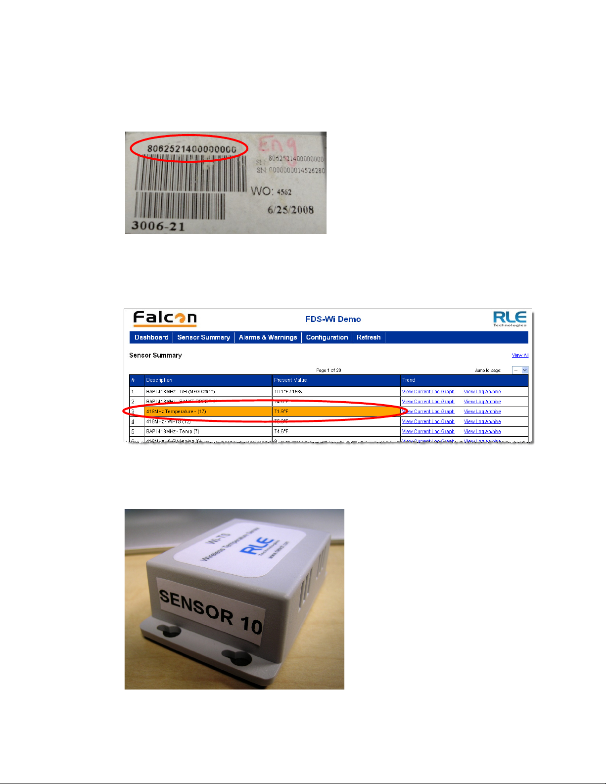
2 Getting Started
4 Turn the sensor over to show the product label on the bottom. This label contains the serial
number of the sensor. The serial number is unique to each sensor, and appears in the table
on the Configuration>Sensors page once the sensor has been discovered by the Wireless
Gateway.
Figure 2.10
5
Go to the Configuration>Sensors page of the Wireless Gateway’s user interface and
Sensor’s Serial Number on Product Label
confirm the placement in the sensor discovery list.
Figure 2.11
6
Place a label or other marking on the sensor to show its index number.
Verifying a Sensor’s Discovery
Figure 2.12
www.rletech.com 20 970.484.6510
Label the Sensor
Page 21
7 Once the sensors have been discovered, turn off the Sensor Discovery option in the
Configuration>FDS-Wi page of the Wireless Gateway’s user interface. If you do not turn
off the sensor discovery feature, the Wireless Gateway will continue to attempt to find new
sensors. This could cause a device malfunction, or contaminate your list of active sensors
with additional sensors that do not actually exist.
8 Note each sensor’s index number and location. Reference Chapter 3, “Web Interface –
Standard Version” on page 23 to learn how to enter the location and any other necessary
identifying information in each sensor’s configuration information.
9 Once you have configured the Wireless Gateway, save a copy of the system configuration.
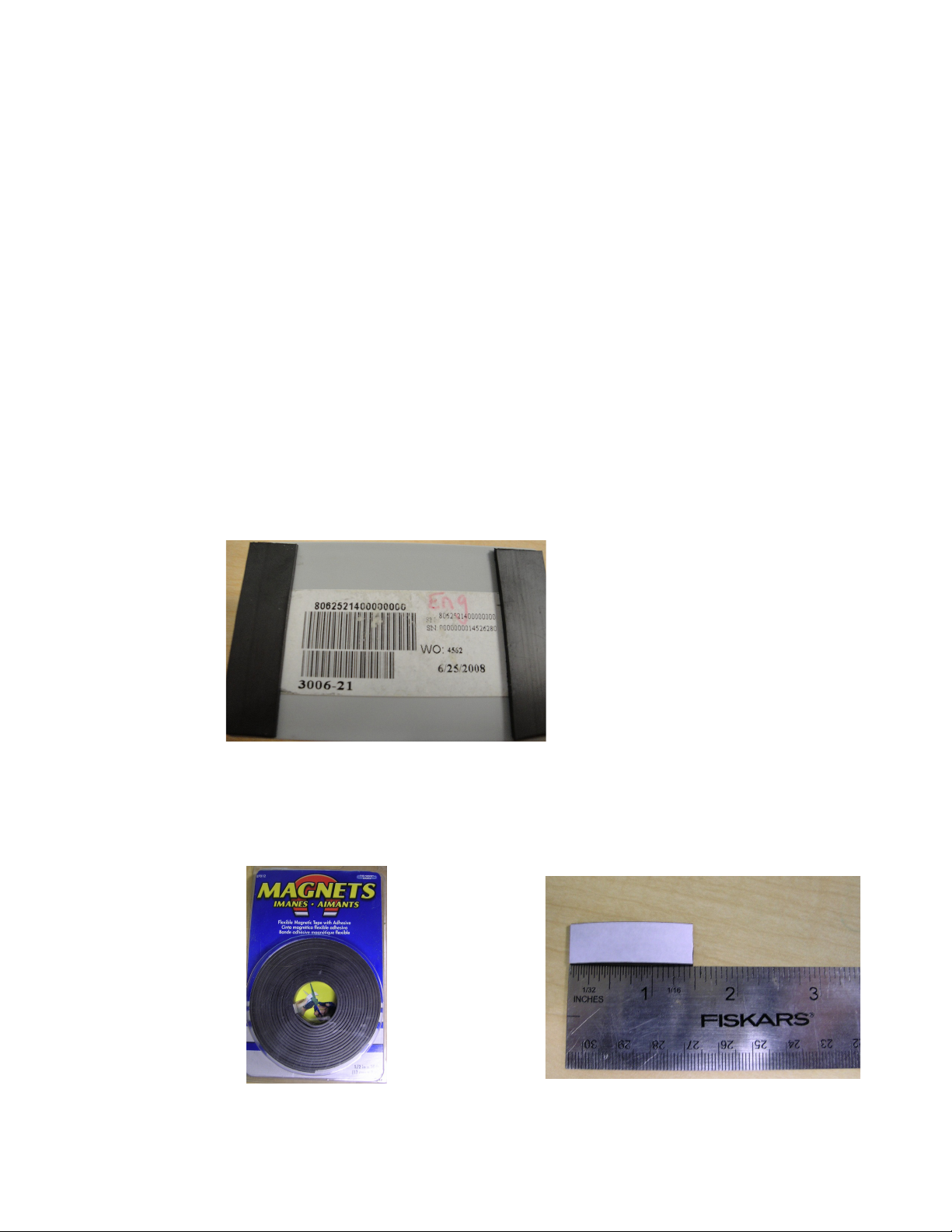
2.6. Sensor Mounting Tips
The electronics in a wireless sensor are water-resistant, but not waterproof. Wireless sensors
need to be mounted in a safe location, where the chance of them becoming submerged in a
liquid are minimal. Sensors can be mounted with double-faced tape or adhesive velcro. To
mount a sensor on a metallic surface, purchase adhesive-backed magnetic tape and adhere it to
the back of the sensor. Use magnetic tape that is 0.5 inch (1.27cm) wide. The magnetic tape
will not disturb the electronics, and when placed correctly, the tape allows the sensor’s label to
remain visible. The serial number on this label is unique to each sensor, and you will need to
refer to this number throughout the life span of the sensor.
2 Getting Started
Figure 2.13
Magnetic Strips Used to Mount a Sensor
To mount sensors using magnetic tape:
1 For each sensor, cut two 1.5-inch (3.81cm) strips of tape.
Figure 2.14
www.rletech.com 21 970.484.6510
Recommended Length of 0.5 Inch for Magnetic Strip
Page 22

2 Getting Started
2 Make sure the back of the sensor is clean. If necessary, use isopropyl alcohol to clean the
sensor.
3 Remove the protective film from the adhesive side of the magnetic tape and place the tape
on the sensor.
4 Place the sensor in the desired location.
www.rletech.com 22 970.484.6510
Page 23
C HAPTER
CHAPTER 0WEB INTERFACE – STANDARD VERSION
The Wireless Gateway allows users to view data points and configure the unit/points via the
Web. To access the Web interfaces, users must first setup the Wireless Gateway to
communicate via the Internet. To set the IP address, see section 2.4., “Communication: Set the
IP Address” on page 17.
Note See Chapter 4, “Web Interface – Integration Version” on page 45 for information about the
integrator version of the web interface.
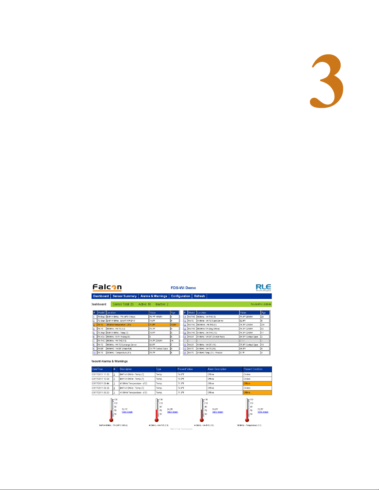
3.1. The Dashboard
The Dashboard provides a quick view of a portion of the information accessible through the
web interface. The Dashboard is fully configurable, so the information most critical to a site’s
operations can be monitored at a glance.
Figure 3.1
www.rletech.com 23 970.484.6510
Wireless Gateway Dashboard
Page 24

3 Web Interface – Standard Version
Sensors on the Dashboard are color coded to help notify users of alarm conditions.
Color Indication
No Color Sensor is registering properly—sensor is communicating properly
Red Sensor is registering properly—sensor has an analog/digital alarm
Yellow Sensor is registering properly—sensor has an analog warning
Orange Sensor is offline—problems with the communications
Table 3.1
Dashboard Alarm Color Codes
From the homepage, users can also navigate to the Configuration page, edit individual sensor
proprieties, refresh the Wireless Gateway signal, and navigate to the Help page.
3.2. Sensor Summary Page
The Sensor Summary page allows users to view all the sensors accessible through the Wireless
Gateway. Up to twenty sensors can be displayed per page, and there are twenty pages
available. The page displays a # link, description, present value and trending information.
Click the number link to access the configuration information for that particular sensor. To
learn more about sensor configuration, reference section 3.6., “Configuration Page - Sensors
Tab” on page 36.
Figure 3.2
Option Description
# Link Click on the sensor number to go to the sensor’s configuration page.
Description A label describing the sensor type and/or location.
Present Value Displays the current sensor reading.
Trend Click the links to view either a graph or a log showing the sensor’s
Table 3.2
Sensor Summary Sample Menu
data record from the last 24 hours.
Sensor Summary Menu Options
The Current Log Graph link
www.rletech.com 24 970.484.6510
Page 25

3 Web Interface – Standard Version
Figure 3.3
Current Log Graphs and Log Archive
3.3. Alarms and Warnings Page
This page displays the 40 most recent events from all monitored sensors. If a sensor was in an
alarm state that has since returned to normal, “Return” is noted in the Present Condition field.
If the sensor is still in an alarm state, the alarm will be noted in the Present Condition field.
If the Wireless Gateway’s power is cycled, all entries on this page will be cleared.
Figure 3.4
www.rletech.com 25 970.484.6510
Alarm and Warnings Page
Page 26

3 Web Interface – Standard Version
3.4. Configuration Page - FDS-Wi Tab
The Configuration Page allows users to view and edit a variety of configuration options.
Figure 3.5
Editable system preferences include:
Configuration Page
♦ System Info
♦ System ID
♦ Network and Web
♦ Date
♦ Alarm Options
♦ Wireless
♦ Graph/Log
♦ Dashboard Key Sensors
♦ Dashboard Options
♦ Ethernet Packet Repeat
NOTE If any of these fields are edited, be sure to click the Submit Changes button to
save the changes. If you edit the fields and do not click the Submit Changes
button, all edits will be lost.
www.rletech.com 26 970.484.6510
Page 27
3 Web Interface – Standard Version
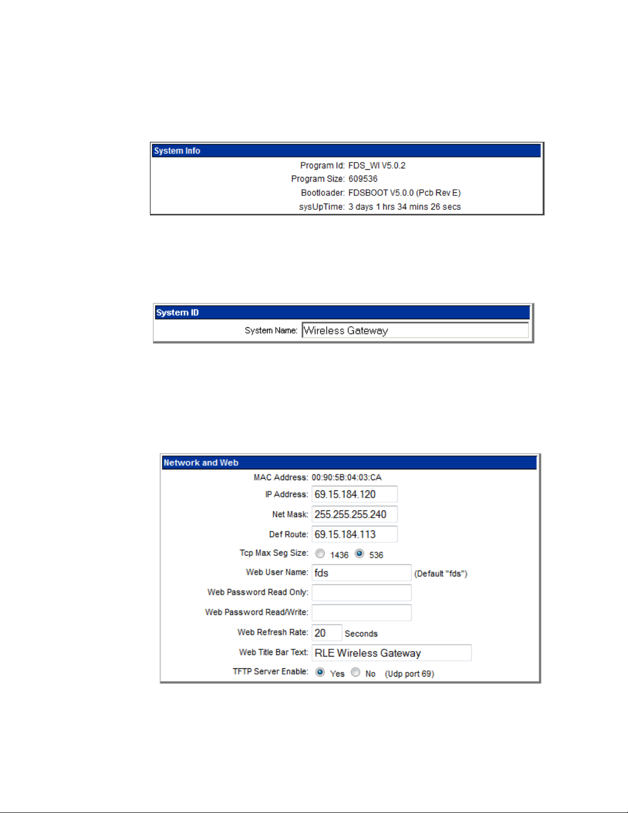
3.4.1 System Info
The System Info section displays detailed information about the system, including the
Program Id (firmware version), Program Size (size of the firmware file), Bootloader Version,
and sysUp Time, or how long the system has been running since power was applied.
Figure 3.6
System Info Section
3.4.2 System ID
Provide the Wireless Gateway with a unique identifier.
Figure 3.7
System ID Section
3.4.3 Network and Web
The Network and Web section displays the assigned MAC Address and allows users configure
common network information.
Figure 3.8
www.rletech.com 27 970.484.6510
Network and Web Section
Page 28

3 Web Interface – Standard Version
Edit the following fields as necessary:
Option Description
IP Address The Wireless Gateway is shipped with a default IP Address of
Net Mask The Wireless Gateway is shipped with a default Subnet Mask of
Default Route The Wireless Gateway comes with a default Gateway Route of
TCP Max Seg Size The Wireless Gateway defaults to 1436 packet size for web page
Web User Name If this field is left blank, the Wireless Gateway’s default user name
10.0.0.188. Contact your IT Department for an appropriate IP
address, if you wish to change this field.
255.255.255.0.
10.0.0.1. Contact your IT Department for help with this setting.
data. Users may select 536 for limited bandwidth or VPN
applications.
is fds (all lower case). Users can enter a user name up to 18
characters, either alpha, numeric, or a combination of the two. The
Wireless Gateway user name is case sensitive.
Web Password Read
Only
Two separate passwords can be established on the Wireless
Gateway.
The Read Only password allows users to access the Wireless
Gateway Web interface and view the conditions of the sensors, but
does not allow users to make changes to the Wireless Gateway
configuration.
Web Password
Read/Write
The second configurable password on the Wireless Gateway
provides users with expanded access.
The Read/Write password allows users to view the condition of the
sensors and make changes to the Wireless Gateway configuration.
Web Refresh Rate The Web Refresh Rate is the amount of time the system waits until
it updates the Web interface with current data. To change the rate,
click in the field and type in the desired amount of time (in seconds).
The minimum recommended refresh rate is five seconds;
otherwise, errors may occur that prevent the system from
functioning properly.
The default refresh rate is set to 0 - the Wireless Gateway will not
refresh at all. Users must set a refresh rate in order for the system
to automatically update.
Web Title Bar Text The text that’s displayed in the title bar of the web browser.
TFTP Server Enable Decide whether the TFTP server capabilities are enabled or not.
Table 3.3
www.rletech.com 28 970.484.6510
Network and Web Section Options
Page 29

3 Web Interface – Standard Version
3.4.4 Date
The Date section allows users to set the current date and time for the system and displays the
first three letters of the day of the week.
Figure 3.9
Option Description
Date Enter the date in mm/dd/yy format.
Time Entered the current time in hh:mm:ss format, where the hour is a
Table 3.4
Date Section
two digit number between 01 and 24.
Date Section Options
3.4.5 Alarm Options
Use the Alarm Options setting to set the Wireless Gateway re-alarm function. The device will
re-send an alarm after a point has been in alarm for a certain number of hours.
Figure 3.10
Option Description
Alarm Option Select a re-alarm time from 1–24 hours. Set the re-alarm time to 0
Table 3.5
Alarm Options Section
to disable the feature.
Alarm Section Option
www.rletech.com 29 970.484.6510
Page 30

3 Web Interface – Standard Version
3.4.6 Wireless
Use this menu to configure wireless options on the Wireless Gateway.
Figure 3.11
Option Description
Wi418/433 Receiver
Wi900/2.4G Receiver
Sensor Discovery Enabled: This is the Wireless Gateway’s default setting. When
Sensor Types Designate whether your system uses only Bapi Sensors, only Point
Wireless Section
Enabled: Turns on the Wireless Gateway’s 418/433 MHz and
900MHz/2.4GHz antennas. This allows the FDS-Wi to
communicate with devices on the respective wavelengths.
Disable: Turns the antennas off and prohibits the Wireless Gateway
from communicating with devices on the respective wavelengths.
sensor discovery is enabled, the Wireless Gateway automatically
discovers new sensors transmitting to it. The Wi loads the newly
detected sensor’s type and serial number in its next available
sensor number.
Disabled: Once you’re done with the sensor discovery process,
set this option to disabled. This prevents the Wireless Gateway
from seeing transmissions from new sensors, and keeps your
system from logging sensors that may not actually exist. Set
Sensory Discovery to Disabled and click on the submit changes
button.
Six Sensors, or a combination of the two.
Bapi Serial Number
Order
Temperature
Conversation
Set All Offline
Delays
Table 3.6
www.rletech.com 30 970.484.6510
Wireless Section Options
If your system uses Bapi sensors, indicate whether the serial
numbers should be read forward or backward by the Wireless
Gateway. In most instances, the serial numbers should be read
forwards. If the Bapi sensors are an older generation, the serial
number may need to be read backward.
Select whether the temperature on the main page displays as
celsius or Fahrenheit.
Users can designate how many minutes must pass before the
FDS-Wi considers the sensor offline. Typical transmission time is
10-20 seconds for 418MHz sensors and 3-5 minutes for 900MHz
sensors.
Page 31

3 Web Interface – Standard Version
3.4.7 Graph/Log
Use this option to determine how frequently the sensors are sampled - every 5 or 10 minutes for graphing and logging purposes.
Figure 3.12
Option Description
Graph/Log Select the 5 minute or 10 minute option.
Log Data Range The FDS-Wi will log temperature readings that falls within a
Table 3.7
Graph/Log Section
designated range. Select the range that best suits your application.
Graph/Log Section Option
3.4.8 Dashboard Key Sensors
Use this section to enable or disable the sensor display on the Dashboard, and designate which
20 sensors are displayed on the Dashboard. By default, this feature is disabled.
Figure 3.13
Option Description
Dashboard Key
Sensors
Table 3.8
www.rletech.com 31 970.484.6510
Dashboard Key Sensors Section
Enable or diable the sensor display.
Select up to 20 different sensors to be displayed on the Dashboard.
Dashboard Key Sensors Section Option
Page 32

3 Web Interface – Standard Version
3.4.9 Dashboard Options
Use this section to enable or disable the recent alarm table and thermometer displays on the
Dashboard. Designate which thermometers are displayed.
Figure 3.14
Option Description
Dashboard Option Enable or disable the recent alarm table and thermometer display.
Table 3.9
Dashboard Options Section
Designate which temperature sensors are displayed on the
Dashboard.
Dashboard Option Section Options
3.4.10 Ethernet Packet Repeat
Use this feature to allow the Wireless Gateway to transmit sensor information over the
network (via port 6767) to another Wireless Gateway.
Figure 3.15
Ethernet Packet Repeat Section
Option Description
Ethernet Packet
Repeat
Table 3.10
www.rletech.com 32 970.484.6510
Ethernet Packet Repeat Section Options
Enable or disable this option.
Select enabled or enabled with labels and enter the IP address of
the Wireless Gateway to which you wish to send the sensor
information.
Page 33
3 Web Interface – Standard Version
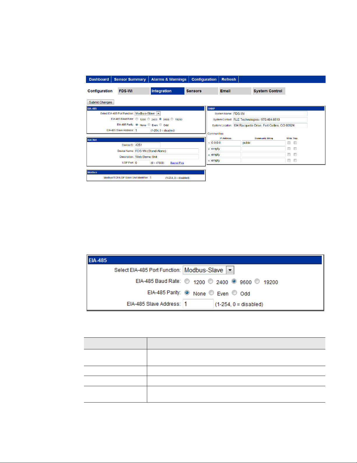
3.5. Configuration Page - Integration Tab
The Integration tab is made up of four configurable sections, which allow users to edit the
following options:
Figure 3.16
Configuration Page, Integration Tab
Use the interface to edit the following fields, taking care to click the Submit Changes button
to save any changes you may have made.
3.5.1 EIA-485
Use this section to configure the system’s EIA-485 port settings.
Figure 3.17
Option Description’
EIA-485 Port
Function
EIA-485 Section
Set the output type for the EIA-485 port to either Modbus-Slave or
Bacnet-MS/TP.
EIA-485 Baud Rate Select 1200, 2400, 9600(default) or 19200.
EIA-485 Parity Select None (default), Even or Odd.
EIA-485 Slave
Address
Table 3.11
www.rletech.com 33 970.484.6510
EIA-485 Section Options
Set a RTU address from 1–254. If the field is left at 0, there is no
transmission on the EIA-485 port.
Page 34

3 Web Interface – Standard Version
3.5.2 BACnet/IP
The BACnet/IP configuration section allows users to configure several settings.
Figure 3.18
Option Description
Device ID Assign a name to uniquely identify each BACnet device on the
Device Name Assign a name - up to 40 characters - to the unit for BACnet
Description Add any additional details about the device. 40 characters,
UDP Port The default port is 0=47808. If a you would like to use a specific
BBMD Data The values in the broadcast distribution table represent IP
Table 3.12
BACnet Section
network.
discovery/integration.
maximum.
port for security reasons, enter a new port number in this field.
addresses and masks. Shown here for reference, the values are
editable via BACnet.
BACnet Section Options
www.rletech.com 34 970.484.6510
Page 35
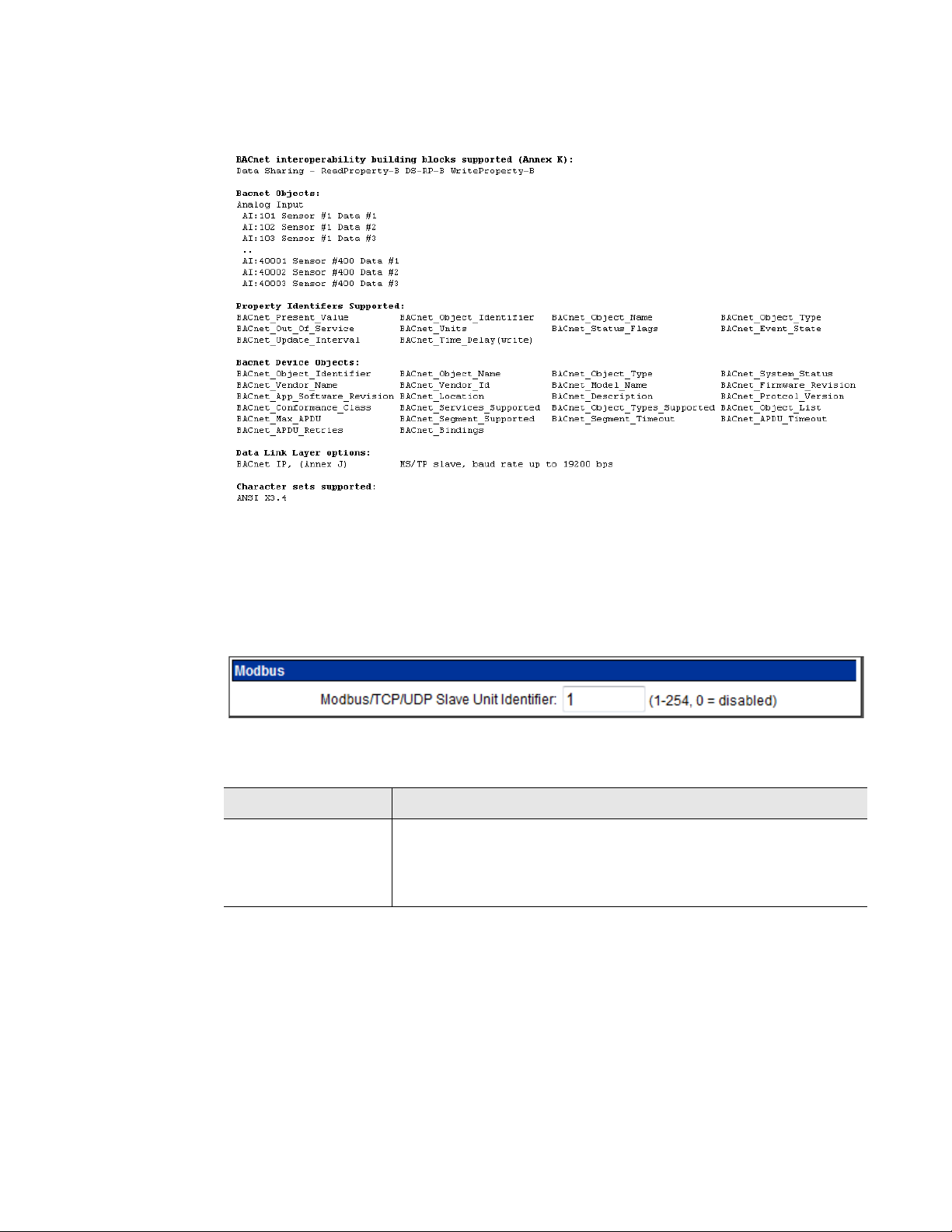
3 Web Interface – Standard Version
The BACnet pics link displays general BACnet capabilities of the device (e.g., what LAN
options are available).
Figure 3.19
General BACnet Capabilities of the Device
3.5.3 Modbus
The Modbus section allows users to configure the Modbus settings for the system.
Figure 3.20
Option Description
Modbus/TCP/UDP
Slave Unit Identifier
Table 3.13
Modbus Section
The default slave unit identifier is 0, which disables this feature.
To enable this option, enter a TCP/UDP slave address from 1-254
in this field. In most instances, the identifier is typically set at 1.
Modbus Section Option
3.5.4 SNMP
The SNMP configuration section also allows users to setup communities that allow multiple
SNMP systems to access the Wireless Gateway. To setup communities, you must know the IP
address of the SNMP Management system and the Community String. Contact your IT
Department to obtain the IP Address and Community String. To configure communities, enter
www.rletech.com 35 970.484.6510
Page 36

3 Web Interface – Standard Version
the IP address and the community string in the designated fields. Each text field
accommodates up to 64 characters.
Figure 3.21
Option Description
System Name Name assigned to the Wireless Gateway for SNMP system
System Contact System Contact responsible for the Wireless Gateway.
System Location Description of the Wireless Gateway location.
Communities: IP
Address
Community String Name or type of password used by the SNMP server for
Write Allows the SNMP server to write back the Wireless Gateway.
Trap Allows the Wireless Gateway to send a message to the SNMP
Table 3.14
SNMP Section
integration.
IP address used by the SNMP server to poll data from the Wireless
Gateway.
communications.
Management System, telling the system to initiate an alarm.
SNMP Section Options
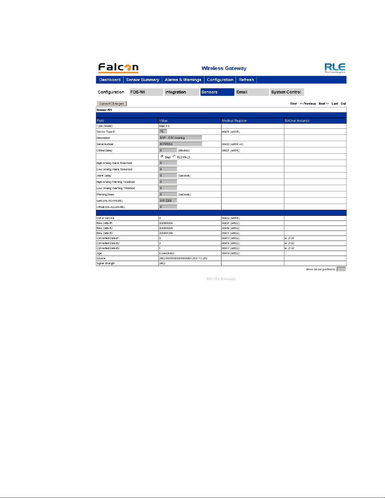
3.6. Configuration Page - Sensors Tab
For each sensor, you can edit all fields in gray. All other fields are for reference. To the right of
the Value field is the corresponding Modbus Register for slave data output from that sensor.
To the right of that is the BACnet Instance number for slave interface to a Building
Management System.
www.rletech.com 36 970.484.6510
Page 37
3 Web Interface – Standard Version
All fields in the following table will not be available for each sensor. Only the configurable
options that apply to each sensor are displayed in that sensor’s configuration menu.
Figure 3.22
Sensors Tab
www.rletech.com 37 970.484.6510
Page 38

3 Web Interface – Standard Version
Editable options are as follows:
Option Description
Sensor Type ID This number is used by the Wireless Gateway to identify what kind
Description Enter a label up to 30 characters to describe the sensor and its
of sensor is being read in to the system. The possible values are:
BAPI 76
Counter 11
SetPointOverride 5B
Thermistor 57
Wi-ASx/Wi-MS 41
Wi-DIT 61
Wi-LD 76
Wi-TC9 74
Wi-TH2 52
Wi_THS 48
Wi-TS 54
location.
Serial Number This is the unique number broadcasted from the sensor to the
Wireless Gateway for identification. Each sensor has a unique
serial number. Enter the appropriate serial number, listed on the
bottom of the sensor, in the provided text field.
Offline Delay Users can designate how many minutes must pass before the
Wireless Gateway considers the sensor offline. Typical
transmission time is 10-20 seconds for 418MHz sensors and 3-5
minutes for 900MHz sensors.
Bapi / RLE Wi-LD
Radio Buttons
Bapi sensors and RLE’s Wi-LD sensor have the same sensor type
ID - 76. If this field is available in your interface, this means the
sensor you’re configuring has a sensor type ID of 76. Designate
whether this sensor is a Bapi sensor or RLE’s Wi-LD.
High Analog Alarm
Threshold
Low Analog Alarm
Threshold
High Temperature
Alarm Threshold
Low Temperature
Alarm Threshold
High Humidity Alarm
Threshold
Enter a high alarm threshold - if the value rises above this number,
an alarm is generated for this sensor.
Enter a low alarm threshold - if the value drops below this number,
an alarm is generated for this sensor.
Enter a high temperature alarm threshold - if the temperature rises
above this value, a high temperature alarm is generated.
Enter a low temperature alarm threshold - if the temperature drops
below this value, a low temperature alarm is generated.
Enter a high humidity alarm threshold - if the humidity rises above
this value, a high humidity alarm is generated.
Low Humidity Alarm
Threshold
Enter a low humidity alarm threshold - if the humidity drops below
this value, a low humidity alarm is generated.
Alarm Delay The number of seconds that pass between the time the system
goes into alarm and the time that alarm is annunciated.
High Temperature
Warning Threshold
Table 3.15
www.rletech.com 38 970.484.6510
Sensors Tab Configuration Options
Enter a high temperature warning threshold - if the temperature
rises above this value, a high temperature warning is generated.
Page 39

Option Description
3 Web Interface – Standard Version
Low Temperature
Warning Threshold
High Humidity
Warning Threshold
Low Humidity
Warning Threshold
Warning Delay The number of seconds that pass between the time the system
Gain (Wi-ASx/WiMS)
and
Offset (Wi-ASx/WiMS)
Enter a low temperature warning threshold - if the temperature
drops below this value, a low temperature warning is generated.
Enter a high humidity warning threshold - if the humidity rises above
this value, a high humidity warning is generated.
Enter a low humidity warning threshold - if the humidity drops below
this value, a low humidity warning is generated.
goes into a warning state and the time that warning is annunciated.
Gain and offset values should be entered for Bapi sensors and
other analog sensors. Gain and offset values for sensors are as
follows:
0-5V Sensor (Bapi)
– Gain: 0.012200
– Offset: 0
0-10V Sensor (Bapi)
– Gain: 0.024400
– Offset: 0
4-20mA Sensor (Bapi)
– Gain: 0.003906
– Offset: 4
Move senor position toReorder the sensors by typing the appropriate number in this box.
Table 3.15
Sensors Tab Configuration Options (continued)
NOTE When the desired edits have been made, click the Submit Changes button to save
the changes. If the Submit Changes button is not selected, the new configuration
will not be updated and saved.
Several fields on this screen are read-only - you can view the data but not edit it. These fields
include:
Option Description
Type (Model) This label is derived from the value entered into the Sensor Type ID
field.
Out Of Service A binary number used to determine if the senor is online or offline.
Raw Data #1-3 This is the uncalculated data received from the wireless sensor.
This data is then processed by the Wireless Gateway to a
calculated value.
Table 3.16
Sensors Tab Read-only Data
www.rletech.com 39 970.484.6510
Page 40

3 Web Interface – Standard Version
Option Description
Converted Data #1-3 This is the calculated data processed from the raw data. This data
Age The amount of time that has passed since the last received
Source Displays to the user where the signal is coming from. 418 is
Signal Strength Displays the quality of the signal from the sensor. 418MHz sensors
Move senor position toThis allows users to enter a new sensor number location
is then displayed on the main page of the Wireless Gateway and
used for Modbus, SNMP and BACnet output.
transmission from this particular wireless sensor.
broadcasted from the common sensor 418MHz Point Six Wireless
sensor. A 900 means it is being broadcasted from a Point Repeater
(Wi-PR) or a 900MHz Point Six Wireless sensor. A 2402 means it is
being received from another Wireless Gateway using the Ethernet
Packet Repeater feature. The MAC address and IP address will be
displayed after the 2402.
display between 0-100.
Table 3.16
Sensors Tab Read-only Data
Navigate to the previous or next sensor in the list of sensors by selecting “Prev” or “Next” on
the upper-right of the webpage. To go to the first sensor on the list, select “First”. To go to the
last connected sensor, click “Last”. If you want to go to the end of the sensor list regardless of
whether a sensor is connected, click “End”. To navigate to individual sensor pages, select the
appropriate page number (1-5) in the upper-right corner.
3.7. Configuration Page - Email Tab
The Email tab allows users to configure the email communications options. Email can be sent
to an exchange server using a distribution list, an individual email account, or a cell phone.
The Wireless Gateway can also communicate via SMTP (Authenticated) to mail servers
requiring a login in name and password.
Figure 3.23
www.rletech.com 40 970.484.6510
Email Tab
Page 41
3 Web Interface – Standard Version
Option Description
Access Type None: Email is not used or is temporarily disabled
LAN: Enable the email notification.
Primary DNS Server First IP address used to communicate to a DNS server.
Secondary DNS
Server
Mail(SMTP)Server IP address or mail server host name used by the FDS-Wi
Mail Sender Address Email address used by the Wireless Gateway.
Mail Subject Description to be displayed on the email notification subject line.
Mail Recipient(1-4) Address for an email account, cell phone or distribution list.
SMTP
Authentication
Smtp Username Username for SMTP Authentication
Smtp Password Password for SMTP Authentication
Table 3.17
SMTP/Email Configuration Options
Second IP address used to communicate to a DNS server.
None: no username or password.
Plain: standard Username and password authentication.
Login is used for certain mail servers. Do not use this unless
instructed by your IT department.
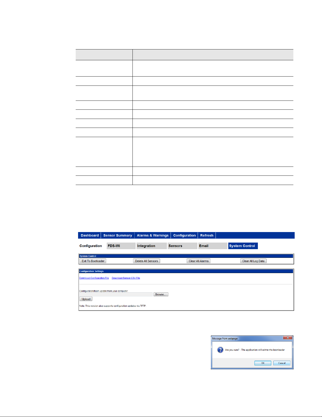
3.8. Configuration Page - System Control Tab
The System Control tab allows users execute a variety of system commands. The messages
shown in the screen shots below may vary, depending on the web browser you’re using.
Figure 3.24
System Control Tab
3.8.1 Exit to Bootloader Button
Allows users to upload new versions of the firmware.
This action erases the current firmware in order to upload
the new firmware. A warning will pop up asking you if
you are sure.
Figure 3.25
www.rletech.com 41 970.484.6510
Exit to Bootloader Message
Page 42

3 Web Interface – Standard Version
3.8.2 Delete All Sensors Button
This command erases all the information about the
sensors the Wireless Gateway is currently reading.
Users will have to reinstall sensor information after
this command has been performed or rediscover
sensors already deployed.
3.8.3 Clear All Alarms Button
This command clears all alarms recorded in the
Alarms and Warning page.
3.8.4 Clear All Log Data Button
This command erases all logging data stored on the
Wireless Gateway.
3.8.5 Download Configuration File Link
Figure 3.26
Figure 3.27
Figure 3.28
Delete All Sensors Message
Clear All Alarms Message
Clear All Log Data Message
This allows users to download a backup file of the
current Wireless Gateway configuration.
Figure 3.29
Download Configuration File Message
3.8.6 Download Sensor CSV File Link
Allows users to download a CSV file showing the
sensors configured in the Wireless Gateway.
Figure 3.30
www.rletech.com 42 970.484.6510
Download Sensor CSV File Message
Page 43

3 Web Interface – Standard Version
3.8.7 Configuration/Flash Upload
This feature allows users to upload a CSV file, unit configuration (.cfg) file or application
firmware.
Figure 3.31
Upload Message
3.9. Refresh Link
Clicking the Refresh link allows users to manually check for status updates. The Refresh link
is especially helpful if the system's refresh rate is set for a long period of time, or when
connecting new units and sensors. Instead of having to wait for the system to refresh, click the
refresh button to update the system.
To set the Refresh rate, go to the Configuration page and type in the refresh time (in seconds)
in the appropriate field underneath the Network and Web section.
www.rletech.com 43 970.484.6510
Page 44

3 Web Interface – Standard Version
www.rletech.com 44 970.484.6510
Page 45
C HAPTER
C
HAPTER
3
W
EB INTERFACE
The Wireless Gateway allows users to view data points and configure the unit/points via the
Web. To access the Web interfaces, users must first setup the Wireless Gateway to
communicate via the Internet. To set the IP address, see section 2.4., “Communication: Set the
IP Address” on page 17.
The integration version of the web interface is designed for operators and installers who use
the Wireless Gateway not as a standalone tool, but as a component of a larger system. To
display this integration version of the web interface:
– I
NTEGRATION
V
ERSION
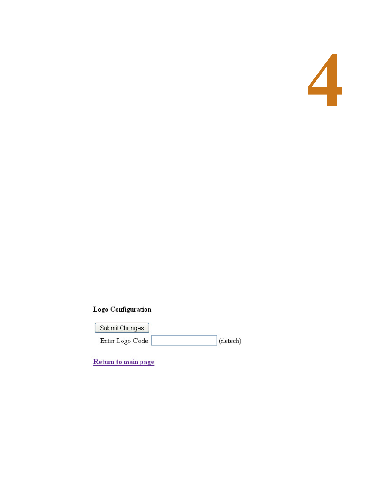
1 In your Web browser, type
http://10.0.0.123/logocfg.htm
2 Press Enter.
The Logo Configuration page displays.
Figure 4.1
3
Type
4 Depending on your browser, you might need to close and reopen it to get the FMS classic
view to display.
Logo Configuration Page (For Displaying “Classic” View)
classic
in the Logo Code field and click the Submit Changes button.
/logocfg.htm
after the IP address for the FMS. For example:
Once you log back in, the FMS classic view displays (see “The Homepage” on page 46).
www.rletech.com 45 970.484.6510
Page 46

4 Web Interface – Integration Version
5 To switch back to the standard view, repeat these steps and type
Configuration field.
4.1. The Homepage
The homepage allows users to view the first 40 sensors outputting signals to the Wireless
Gateway. Each sensor is color coded to help notify users of alarms.
standard
in the Logo
Figure 4.2
Color Meaning
Green Sensor is registering properly—sensor is communicating properly
Red Sensor is registering properly—sensor has an analog/digital alarm
Yellow Sensor is registering properly—sensor has an analog warning
Orange Sensor is offline—problems with the communications
Table 4.1
Wireless Gateway Homepage
Color Codes for Homepage
The “Sensor Pages” links at the top right corner of the screen allow you to scroll through all
the sensors monitored by the Wireless Gateway. Each page displays 40 sensors. Click the
appropriate page link to view your sensors.
www.rletech.com 46 970.484.6510
Page 47

4 Web Interface – Integration Version
4.1.1 View All Sensor IDs
For a single-screen view of all sensors connected to they system, click the “View All Sensor
IDs” link located in the bottom left corner of the screen.
Figure 4.3
Use the scroll bar to view sensors towards the bottom of the list. Each row is numbered and
contains three pieces of information. The number on the left displays the system number
(identifier) assigned to the sensor. The middle column displays the serial number of the sensor
and the right number displays the age of the data on the sensor, or how long it has been
running, in seconds, since the last measurement was read.
The top of the page displays the total sensors connected to the Wireless Gateway, the active
sensors that are currently communicating with the Wireless Gateway, and the total inactive
sensors that are not currently communicating with the Wireless Gateway. To navigate to
individual sensor pages, select the appropriate page number (1-5) in the upper-right corner.
View All Sensors Page
4.1.2 Individual Sensor Configuration
Whether you’re viewing the sensors through the Sensor Pages or the View All option, note
that each sensor’s system number (identifier) is a clickable number link. Click this link to
access the sensor’s configuration page.
Each sensor has its own configuration page which allows users to edit a wide variety of sensor
information. The Wireless Gateway’s sensor discovery feature automatically checks and
updates the serial numbers of sensors once they are connected to the system. Therefore, if the
sensor discovery feature is enabled (4.2.1, “Wireless” on page 53), sensors communicating
with the system should automatically be connected to the Wireless Gateway.
If a serial number is not automatically updated and needs to be entered manually, the serial
number should be entered from left to right. Point Six sensors have two serial numbers on the
sensors, one that reads from left to right and one that reads from right to left. The serial
number should be entered starting with a number (not zero) or an alpha character.
www.rletech.com 47 970.484.6510
Page 48

4 Web Interface – Integration Version
Click on a sensor number to edit.
If a sensor needs to be edited or manually entered, click the sensor’s system number
(identifier) # link—displayed in blue and underlined to the left of each sensor row.
Figure 4.4
Editing Sensor Properties
Click the number in the left side of the sensor row to edit individual sensor properties.
Figure 4.5
Wireless Sensor Configuration
For each sensor, you can edit all fields in gray. All other fields are for reference. To the right of
the Value field is the corresponding Modbus Register for slave data output from that sensor.
To the right of that is the BACnet Instance number for slave interface to a Building
Management System.
www.rletech.com 48 970.484.6510
Page 49

4 Web Interface – Integration Version
All fields in the following table will not be available for each sensor. Only the configurable
options that apply to each sensor are displayed in that sensor’s configuration menu. Editable
options are as follows:
Option Description
Model To edit the sensor model, select the type of model from the drop-
down list by clicking on the down arrow to the direct right of the
sensor model field.
This number is used by the Wireless Gateway to identify what kind
of sensor is being read in to the system. The possible values are:
BAPI 76
Counter 11
SetPointOverride 5B
Thermistor 57
Wi-ASx/Wi-MS 41
Wi-DIT 61
Wi-LD 76
Wi-TC9 74
Wi-TH2 52
Wi_THS 48
Wi-TS 54
Serial Number This is the unique number broadcasted from the sensor to the
Wireless Gateway for identification. Each sensor has a unique
serial number. Enter the appropriate serial number, listed on the
bottom of the sensor, in the provided text field.
Offline Delay Users can designate how many minutes must pass before the
Wireless Gateway considers the sensor offline. Typical
transmission time is 10-20 seconds for 418MHz sensors and 3-5
minutes for 900MHz sensors.
Location/
Description
High Temperature/
Analog Alarm
Threshold
Low Temperature/
Analog Alarm
Threshold
High Temperature
Alarm Threshold
Low Temperature
Alarm Threshold
High Humidity Alarm
Threshold
Enter a label up to 30 characters to describe the sensor and its
location.
Enter a high alarm threshold - if the value rises above this number,
an alarm is generated for this sensor.
Enter a low alarm threshold - if the value drops below this number,
an alarm is generated for this sensor.
Enter a high temperature alarm threshold - if the temperature rises
above this value, a high temperature alarm is generated.
Enter a low temperature alarm threshold - if the temperature drops
below this value, a low temperature alarm is generated.
Enter a high humidity alarm threshold - if the humidity rises above
this value, a high humidity alarm is generated.
Low Humidity Alarm
Threshold
Alarm Delay The number of seconds that pass between the time the system
Table 4.2
www.rletech.com 49 970.484.6510
Wireless Sensor Configuration Options
Enter a low humidity alarm threshold - if the humidity drops below
this value, a low humidity alarm is generated.
goes into alarm and the time that alarm is annunciated.
Page 50

4 Web Interface – Integration Version
Option Description
High Temperature
Warning Threshold
Low Temperature
Warning Threshold
High Humidity
Warning Threshold
Low Humidity
Warning Threshold
Warning Delay The number of seconds that pass between the time the system
Gain (Wi-ASx/WiMS)
and
Offset (Wi-ASx/WiMS)
Enter a high temperature warning threshold - if the temperature
rises above this value, a high temperature warning is generated.
Enter a low temperature warning threshold - if the temperature
drops below this value, a low temperature warning is generated.
Enter a high humidity warning threshold - if the humidity rises above
this value, a high humidity warning is generated.
Enter a low humidity warning threshold - if the humidity drops below
this value, a low humidity warning is generated.
goes into a warning state and the time that warning is annunciated.
Gain and offset values should be entered for Bapi sensors and
other analog sensors. Gain and offset values for sensors are as
follows:
0-5V Sensor (Bapi)
– Gain: 0.012200
– Offset: 0
0-10V Sensor (Bapi)
– Gain: 0.024400
– Offset: 0
4-20mA Sensor (Bapi)
– Gain: 0.003906
– Offset: 4
Contact Alarm (WiDIT/Wi-TC9/BapiWDI)
Move senor position toReorder the sensors by typing the appropriate number in this box.
Table 4.2
Wireless Sensor Configuration Options (continued)
Select One: Normally Open / Normally Closed
Select One: Alarm / Status
NOTE When the desired edits have been made, click the Submit Changes button to save
the changes. If the Submit Changes button is not selected, the new configuration
will not be updated and saved.
www.rletech.com 50 970.484.6510
Page 51

4 Web Interface – Integration Version
Several fields on this screen are read-only - you can view the data but not edit it. These fields
include:
Option Description
ID Specified in the Model field, this number is used by the Wireless
Gateway to identify what kind of sensor is being read in to the
system.
Out Of Service A binary number used to determine if the senor is online or offline.
Raw Data #1-3 This is the uncalculated data received from the wireless sensor.
This data is then processed by the Wireless Gateway to a
calculated value.
Converted Data #1-3 This is the calculated data processed from the raw data. This data
is then displayed on the main page of the Wireless Gateway and
used for Modbus, SNMP and BACnet output.
Age The amount of time that has passed since the last received
transmission from this particular wireless sensor.
Source Displays to the user where the signal is coming from. 418 is
broadcasted from the common sensor 418MHz Point Six Wireless
sensor. A 900 means it is being broadcasted from a Point Repeater
(Wi-PR) or a 900MHz Point Six Wireless sensor. A 2402 means it is
being received from another Wireless Gateway using the Ethernet
Packet Repeater feature. The MAC address and IP address will be
displayed after the 2402.
Signal Strength Displays the quality of the signal from the sensor. 418MHz sensors
display between 0-100.
Navigate to the previous or next sensor in the list of sensors by selecting “Prev” or “Next” on
the upper-right of the web page. To go to the first sensor on the list, select “First”. To go to the
last connected sensor, click “Last”. If you want to go to the end of the sensor list regardless of
whether a sensor is connected, click “End”. To navigate to individual sensor pages, select the
appropriate page number (1-5) in the upper-right corner.
www.rletech.com 51 970.484.6510
Page 52

4 Web Interface – Integration Version
4.2. Configuration Page
The configuration page allows users to set the system preferences.
Figure 4.6
Editable system preferences include:
Configuration Page
♦ Wireless
♦ Network and Web
♦ Date
♦ Configuration Upload/
Download
♦ System Control
♦ System Info
♦ EIA-485
♦ BACNet
♦ Modbus
♦ Sensor Logging
NOTE If any of these fields are edited, be sure to click the Submit Changes button to
save the changes. If you edit the fields and do not click the Submit Changes
button, all edits will be lost.
www.rletech.com 52 970.484.6510
Page 53

4 Web Interface – Integration Version
4.2.1 Wireless
Use this menu to configure wireless options on the Wireless Gateway.
Figure 4.7
Option Description
Wi418/Wi900
Receiver
Sensor Discovery Enabled: This is the Wireless Gateway’s default setting. When
Sensor Types Designate whether your system uses only Bapi Sensors, only Point
Wireless Section
Enabled: Turns on the Wireless Gateway’s 418 and 900 MHz
antennas. This allows it to communicate with devices on the
respective wavelengths.
Disable: Turns the antennas off and prohibits the Wireless Gateway
from communicating with devices on the respective wavelengths.
sensor discovery is enabled, the Wireless Gateway automatically
discovers new sensors transmitting to it. The Wi loads the newly
detected sensor’s type and serial number in its next available
sensor number.
Disabled: Once you’re done with the sensor discovery process,
set this option to disabled. This prevents the Wireless Gateway
from seeing transmissions from new sensors, and keeps your
system from logging sensors that may not actually exist. Set
Sensory Discovery to Disabled and click on the submit changes
button.
Six Sensors, or a combination of the two.
Bapi Serial Number
Order
Temperature
Conversation
Table 4.3
www.rletech.com 53 970.484.6510
Wireless Section Options
If your system uses Bapi sensors, indicate whether the serial
numbers should be read forward or backward by the Wireless
Gateway. In most instances, the serial numbers should be read
forwards. If the Bapi sensors are an older generation, the serial
number may need to be read backward.
Select whether the temperature on the main page displays as
celsius or Fahrenheit.
Page 54

4 Web Interface – Integration Version
Option Description
Ethernet Packet
Repeat
Alarm Reminder Use the Alarm Options setting to set the Wireless Gateway re-
Table 4.3
Wireless Section Options (continued)
Use this feature to allow the Wireless Gateway to transmit sensor
information over the network (via port 6767) to another Wireless
Gateway.
Enable or disable this option.
Select enabled or enabled with labels and enter the IP address of
the Wireless Gateway to which you wish to send the sensor
information.
alarm function. The device will re-send an alarm after a point has
been in alarm for a certain number of hours.
Select a re-alarm time from 1–24 hours. Set the re-alarm time to 0
to disable the feature.
4.2.2 Network and Web
The Network and Web section displays the MAC Address and allows users configure common
network information
Figure 4.8
Option Description
IP Address The Wireless Gateway is shipped with a default IP Address of
Subnet Mask The Wireless Gateway is shipped with a default Subnet Mask of
Default Route The Wireless Gateway comes with a default Gateway Route of
Table 4.4
www.rletech.com 54 970.484.6510
Network and Web Section
10.0.0.188. Contact your IT Department for an appropriate IP
address, if you wish to change this field.
255.255.255.0
10.0.0.1. Contact your IT Department for help with this setting.
Network and Web Section Options
Page 55

4 Web Interface – Integration Version
Option Description
TCP Max Seg Size The Wireless Gateway is defaulted to 1436 packet size for web
page data. Users may select 536 for limited bandwidth or VPN
applications.
Web User Name If this field is left blank, the Wireless Gateway’s default user name
is fds (all lower case). Users can enter a user name up to 18
characters, either alpha, numeric, or a combination of the two. The
Wireless Gateway user name is case sensitive.
Web Password Read
Only
Web Password
Read/Write
Web Refresh Rate The Web Refresh Rate is the amount of time the system waits until
Table 4.4
Network and Web Section Options (continued)
Two separate passwords can be established on the Wireless
Gateway.
The Read Only password allows users to access the Wireless
Gateway Web interface and view the conditions of the sensors, but
does not allow users to make changes to the Wireless Gateway
configuration.
The second configurable password on the Wireless Gateway
provides users with expanded access.
The Read/Write password allows users to view the condition of the
sensors and make changes to the Wireless Gateway configuration.
it updates the Web interface with current data. To change the rate,
click in the field and type in the desired amount of time (in seconds).
The minimum recommended refresh rate is five seconds;
otherwise, errors may occur that prevent the system from
functioning properly.
The default refresh rate is set to 0 - the Wireless Gateway will not
refresh at all. Users must set a refresh rate in order for the system
to automatically update.
4.2.3 Date
The Date section allows users to set the current date and time for the system and displays the
first three letters of the day of the week.
Figure 4.9
Option Description
Date Enter the date in mm/dd/yy format.
Time Entered the current time in hh:mm:ss format, where the hour is a
Table 4.5
www.rletech.com 55 970.484.6510
Date Section
two digit number between 01 and 24.
Date Section Options
Page 56

4 Web Interface – Integration Version
4.2.4 System Info
The System Info section displays detailed information about the system, including the
Program Id (firmware version), Program Size (size of the firmware file), Bootloader Version,
and sysUp Time, or how long the system has been running since power was applied.
Figure 4.10
System Info Section
4.2.5 EIA-485
Use this section to configure the system’s EIA-485 port settings.
Figure 4.11
Option Description
EIA-485 Port
Function
EIA-485 Baud Rate Select 1200, 2400, 9600(default) or 19200.
EIA-485 Parity Select None (default), Even or Odd.
EIA-485 Slave
Address
Table 4.6
EIA-485 Section
Set the output type for the EIA-485 port to either Modbus-Slave or
Bacnet-MS/TP.
Set a RTU address from 1–254. If the field is left at 0, there is no
transmission on the EIA-485 port.
EIA-485 Section
www.rletech.com 56 970.484.6510
Page 57

4 Web Interface – Integration Version
4.2.6 BACNet
The BACNet configuration section allows users to configure several settings.
Figure 4.12
Option Description
Device ID Assign a name to uniquely identify each BACnet device on the
Device Name Assign a name - up to 40 characters - to the unit for BACnet
Description Add any additional details about the device. 40 characters,
UDP Port The default port is 0=47808. If a you would like to use a specific
Table 4.7
BACNet Section
network.
discovery/integration.
maximum.
port for security reasons, enter a new port number in this field.
BACNet Section Options
The BACnet pics link displays general BACnet capabilities of the device (e.g., what LAN
options are available).
4.2.7 Modbus
The Modbus section allows users to configure the Modbus settings for the system.
Figure 4.13
Option Description
Modbus/TCP/UDP
Slave Unit Identifier
Table 4.8
www.rletech.com 57 970.484.6510
Modbus Section
The default slave unit identifier is 0, which disables this feature.
To enable this option, enter a TCP/UDP slave address from 1-254
in this field. In most instances, the identifier is typically set at 1.
Modbus Section Option
Page 58

4 Web Interface – Integration Version
4.2.8 Sensor Logging
Use this option to determine how frequently the sensors are sampled - every 5 or 10 minutes for graphing and logging purposes.
Figure 4.14
Option Description
Graph/Log Select the 5 minute or 10 minute option.
Table 4.9
Sensor Logging Section
Sensor Logging Section Option
4.2.9 Configuration Upload/Download
This feature allows users to upload a CSV file, unit configuration (.cfg) file or application
firmware. The messages shown in the screen shots below may vary, depending on the web
browser you’re using.
Figure 4.15
Download Configuration File: This allows users to download a back up file of the current
Wireless Gateway configuration.
Configuration Upload/Download Section
Figure 4.16
www.rletech.com 58 970.484.6510
Download Configuration File
Page 59
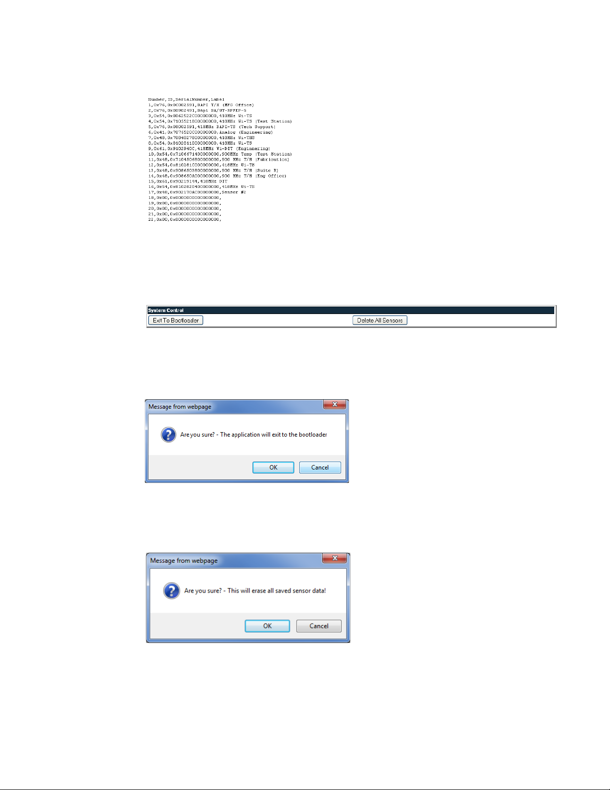
4 Web Interface – Integration Version
Download Sensor CSV File: This allows users to download a CSV file showing the sensors
configured in the Wireless Gateway.
Figure 4.17
Download Sensor CSV File
4.2.10 System Control
This section allows users to exit to bootloader and delete all sensor information associated
with the Wireless Gateway.
Figure 4.18
Exit to Bootloader: This allows users to upload new versions of firmware. This action erases
the current firmware in order to upload the new firmware. A warning will pop up asking you if
you are sure.
Figure 4.19
Delete All Sensors: This command erases all the information about the current sensors the
Wireless Gateway is reading. Users will have to reinstall sensor information after this
command has been performed or rediscover sensors already deployed.
System Control
Exit to Bootloader
Figure 4.20
www.rletech.com 59 970.484.6510
Delete All Sensors
Page 60

4 Web Interface – Integration Version
4.3. Configuration SNMP/SMTP Page
The SNMP section allows users to configure the email communications options. Email can be
sent to an exchange server using a distribution list, an individual email account, or a cell
phone.
The Wireless Gateway can also communicate via SMTP (Authenticated) to mail servers
requiring a login in name and password.
Figure 4.21
Option Description
Access Type None: Email is not used or is temporarily disabled
Primary DNS Server First IP address used to communicate to a DNS server.
Secondary DNS
Server
Mail(SMTP)Server IP address or host name to the mail server used by the Wireless
Mail Sender Address Email address used by the Wireless Gateway.
Mail Subject Description to be displayed on the email notification subject line.
Mail Recipient(1-4) Address for an email account, cell phone or distribution list.
SMTP
Authentication
Smtp Username Username for SMTP Authentication
Smtp Password Password for SMTP Authentication
Table 4.10
SMTP Configuration Section
LAN: Enable the email notification.
Second IP address used to communicate to a DNS server.
Gateway.
None: no username or password.
Plain: standard Username and password authentication.
Login is used for certain mail servers. Do not use this unless
instructed by your IT department.
SNMP Configuration Section Options
www.rletech.com 60 970.484.6510
Page 61

4 Web Interface – Integration Version
The SNMP configuration section also allows users to setup communities that allow multiple
SNMP systems to access the Wireless Gateway. To setup communities, you must know the IP
address of the SNMP Management system and the Community String. Contact your IT
Department to obtain the IP Address and Community String. To configure communities, enter
the IP address and the community string in the designated fields. Each text field
accommodates up to 64 characters.
Figure 4.22
Option Description
System Name Name assigned to the Wireless Gateway for SNMP system
System Contact System Contact responsible for the Wireless Gateway.
System Location Description of the Wireless Gateway location.
Communities: IP
Address
Community String Name or type of password used by the SNMP server for
Write Allows the SNMP server to write back the Wireless Gateway.
Trap Allows the Wireless Gateway to send a message to the SNMP
Table 4.11
SNMP Configuration Section
SNMP Configuration Section Options
4.4. Refresh Link
Clicking the Refresh link allows users to manually check for status updates. The Refresh link
is especially helpful if the system's refresh rate is set for a long period of time, or when
connecting new units and sensors. Instead of having to wait for the system to refresh, click the
refresh button to update the system.
integration.
IP address used by the SNMP server to poll data from the Wireless
Gateway.
communications.
Management Server, telling the system to initiate an alarm.
To set the Refresh rate, go to the Configuration page and type in the refresh time (in seconds)
in the appropriate field underneath the Network and Web section.
www.rletech.com 61 970.484.6510
Page 62

4 Web Interface – Integration Version
www.rletech.com 62 970.484.6510
Page 63

C HAPTER
CHAPTER 0UPDATE FIRMWARE
Firmware updates are available on the RLE Web site at www.rletech.com. Download
appropriate firmware to an accessible location.
5.1. Load the Application Firmware Using MIME
The Wireless Gateway has a MIME (Multipurpose Internet Mail Extensions) built into the
web page interface. A user can download the latest version of firmware from rletech.com to
their local drive, then navigate to the file using the browse button, and then click on upload for
the unit to take the file. This process takes about 60 seconds to complete. The MIME feature
can also be used to upload the unit configuration file.
Figure 5.1
www.rletech.com 63 970.484.6510
MIME Sample
Page 64

5 Update Firmware
5.2. Load the Flash Firmware Using TFTP
Before updating the firmware, the firmware flash application must be exited and then erased.
To do this, navigate to the Wireless Gateway configuration menu. Once here, click on the
“Exit to Bootloader” button. Once exited, you will get a bootloader web page at the IP address
of the unit. Next, click on the “Erase Flash” button. The Flash application will be erased.
Note To erase the flash, a special username and password are required. The username is fds (all
lowercase), and the password is rle2tech (all lowercase).
1
Uploading firmware via TFTP requires a TFTP Client. It may be possible to download a
free license TFTP Client from the internet. Consult your IT department to determine a
compatible client program.
2 Verify that your PC and the Wireless Gateway are on the same subnet (LAN).
3 Open your TFTP client. Configure the client as follows.
a Host = Wireless Gateway IP Address
b Port = 69
c Block Size = 64, 128, 256, 512, or 1024
Note The file must be sent in BINARY (not ASCII).
4
Send or PUT the firmware file to the Wireless Gateway. It may take ~10 seconds for the
firmware upload to begin. This will put the new firmware into effect.
5 After one minute, refresh the Wireless Gateway web page. Notice that the Flash field now
contains the latest firmware. Click the “Start Application” button to reboot the unit.
www.rletech.com 64 970.484.6510
Page 65

CHAPTER 0MODBUS COMMUNICATIONS
A.1. Implementation Basics
The Wireless Gateway is capable of communicating via the half-duplex EIA-485 serial
communication standard. The Wireless Gateway is configured to act as a slave device on a
common network. The EIA-485 medium allows for multiple devices on a multi-drop network.
The Wireless Gateway is a slave only device and will never initiate a communications
sequence.
A PPENDIX
A.1.1 Modes of Transmission
The Modbus protocol uses ASCII and RTU modes of transmission. The Wireless Gateway
supports only the RTU mode of transmission, with 8 data bits, no parity and one stop bit.
Every Modbus packet consists of four fields:
♦ Slave Address Field
♦ Function Field
♦ Data Field
♦ Error Check Field (Checksum)
A.1.1.1 Slave Address Field
The slave address field is one byte in length and identifies the slave device involved in the
transaction. A valid address range is between 1 and 254. The slave address is set from the
Modbus/EIA-485 Configuration webpage.
A.1.1.2 Function Field
The function field is one byte in length and tells the Wireless Gateway which function to
perform. The supported functions are 03 (Read 4xxxx output registers).
www.rletech.com 65 970.484.6510
Page 66

A Modbus Communications
A.1.1.3 Data Field
The data field of the request is a variable length depending on the function. The data fields for
the Wireless Gateway are 16-bit registers, transmitted high order byte first (big-endian)
A.1.1.4 Error Check (Checksum) Field
The checksum field lets the receiving device determine if the packet has transmission errors.
The Wireless Gateway RTU mode uses a 16-bit cyclic redundancy check (CRC-16).
A.1.2 Exception Responses
If a Modbus master sends an invalid command to the Wireless Gateway or attempts to read an
invalid register, an exception response is generated. The response packet will have the high
order bit of the function code set to one. The data field of the exception response contains the
exception error code.
Code Name Description
01 Illegal Function The function code is not supported
02 Illegal Data Address Attempt to access an invalid address
03 Illegal Data Value Attempt to set a variable to an invalid value
Table A.1
Exception Codes
A.2. Packet Communications for the Wireless
Gateway
This section outlines the registers with the name and a brief description of each.
A.2.1 Function 03: Read Output Registers
To read the Wireless Gateway parameter values, the master must send a Read Output
Registers request packet.
The Read Output Registers request packet specifies a start register and the number of registers
to read. The start register is numbered from zero (40001 = zero, 40002 = one, etc.).
Read Registers Request Packet Read Registers Response Packet
Slave Address (1 byte) Slave Address (1 byte)
03 (Function code) (1 byte) 03 (Function code) (1 byte)
Start Register (2 bytes) Byte count (1 byte)
# of registers to read (2 bytes) First register (2 bytes)
Crc Checksum (2 bytes) Second register (2 bytes)
…
Crc Checksum (2 bytes)
Table A.2
www.rletech.com 66 970.484.6510
Read Output Registers Packet Structure
Page 67

A Modbus Communications
Register Name Description Units Range
40001 Id Sensor Identification number uint16 0-65535
40002 Out Of Service Shows when the sensor is in
maintenance mode or offline
40003 Serial # Wireless sensor serial number uint16x4 0-65535
40007 Raw Data #1 First data value displayed by
sensor
40009 Raw Data #2 Second data value displayed
by sensor
40011 Raw Data #3 Third data value displayed by
sensor
40013 Converted Data #1 First data value converted by
the Wireless Gateway
40015 Converted Data #2 Second data value converted
by the Wireless Gateway
40017 Converted Data #3 Third data value converted by
the Wireless Gateway
40019 Age Time since last transmission
received
48001 Offline Delay Time till the sensor reads
offline
Table A.3
Output Registers
uint16 0-65535
Unsigned 32 bit
integer
Unsigned 32 bit
integer
Unsigned 32 bit
integer
Unsigned 32 bit
integer
Unsigned 32 bit
integer
Unsigned 32 bit
integer
Unsigned 32 bit
integer
uint16 0-65535
0-4294967295
0-4294967295
0-4294967295
0-4294967295
0-4294967295
0-4294967295
0-4294967295
A.3. RTU Framing
The example below shows a typical Query/Response from an Wireless Gateway.
Register
Slave
Address
02 04 06 00 00 00 00 00 01 B5 A3
Table A.4
Function
Code
Response Sample
Count Bytes
of Data
Data
Msb Lsb
Slave address 2 responds to Function Code 4 with six bytes of hexadecimal data and ends with
CRC16 checksum.
Register Values:
40001 = 0000 (hex)
40002 = 0000 (hex)
40003 = 0001 (hex)
Register
Data
Msb Lsb
Register
Data
Msb Lsb
CRC 16
“Lsb”
CRC 16
“Msb”
www.rletech.com 67 970.484.6510
Page 68

A Modbus Communications
www.rletech.com 68 970.484.6510
Page 69

A PPENDIX
CHAPTER 1TROUBLESHOOTING
Below you’ll find troubleshooting tips for a variety of situations you may encounter with the
Wireless Gateway. Please use these suggestions to troubleshoot your appliance.
If these troubleshooting tips do not resolve your isues, RLE Technologies offers personalized
support for all our products. If you require customer support for your Wireless Gateway,
please contact RLE Technologies directly:
♦ Email: support@rletech.com
♦ Phone: 800.518.1519
The Wireless Gateway will not power up.
1 Use a digital volt meter (DVM) to check for AC or DC input power on the lower left hand
terminal block on the Wireless Gateway. If no voltage is present at terminal block, check
the circuit breaker or power supply that powers the Wireless Gateway. If voltage is present
at the power supply, continue to step 2.
2 Contact RLE Technologies for further troubleshooting.
You cannot view the Wireless Gateway’s home page.
1 Verify that the Wireless Gateway is powered up and running. You will see lights on the
RJ45 (Ethernet) port illuminated and flashing. If no lights are illuminated on the unit, the unit
may not be powered. If lights are illuminated and flashing, continue to step 2.
2 Connect a computer to the Wireless Gateway via a serial cable and the console port. Once
connected with a terminal emulation program running on the PC:
a Type
b Type
c Type
www.rletech.com 69 970.484.6510
ip and press enter. This displays the current IP address set to the Wireless
Gateway. Verify it is the correct IP address.
nm and press enter. This displays the Net Mask. Verify it is the correct Net Mask.
dg and press enter. This displays the Default Gateway. Verify it is the correct
Default Gateway.
Page 70

B Troubleshooting
d Correct any information that is wrong. If the information is correct, go to step 3.
3 With the serial cable connected and your terminal emulation program running, you can
enter an address to have the Wireless Gateway ping to.
a Obtain a known good IP address.
b In the terminal emulation program, type
then press enter. Example: ping 192.168.1.1
c If a ping response is not established, contact your IT department and make sure the
patch cord your using is not faulty. Have the network switch port checked to make sure it
is activated.
♦ If a ping response is established, contact your local sales representative or RLE
Technologies.
ping <one space> ip address and
Sensors do not display on the Wireless Gateway’s home page.
1 The transmission range of a wireless sensor depends on the distance between the sensor
and the Wireless Gateway, and the number of obstacles between the two. The more
obstructions between the devices, the weaker the signal becomes.
2 Do not install a wireless sensor inside a solid metal cabinet. This can interfere with its
transmission.
3 If the sensor is not visible on the Wireless Gateway’s home page, remove the cover from
the sensor and see if the red “heartbeat” LED is flashing once every ten seconds. If you do
not see a flash, check the sensor’s batteries. If you do see it flash, continue to step 2.
4 Bring the sensor closer to the FSD-Wi and push the reset button on the top of the unit. If the
sensor does not show on the home page when it is close to the Wireless Gateway, contact
your local sales representative or RLE Technologies. If the sensor does show on the home
page, move the sensor back to its original location.
5 418 MHz sensors have a limited range and may loose signal quality due to distance or
physical obstructions. If moving the sensor to its original location causes the signal to be
lost again, you have several options.
a Move the sensor to another acceptable location, where it can be “seen” by the Wireless
Gateway.
b Switch out the 418 MHz sensor for a 900MHz sensor. The 900 MHz sensor will have a
greater range.
c Use a point repeater to improve the signal quality.
Sensors that you have NOT installed appear on the Wireless Gateway’s
home page.
This issue may occur when wireless sensors are used in conjunction with an Wireless
Gateway. When you installed your sensors, the automatic Sensor Discovery feature on the
Wireless Gateway was enabled. Initially everything configured correctly, but when you check
the Wireless Gateway several days later, it reports far more sensors than you have installed,
and some of the reported data is very old.
When you configured your system, you left the Sensor Discovery feature on the Wireless
Gateway enabled. The sensors sometimes transmit messages with garbled data packets, and
the Wireless Gateway has interpreted the garbled data as new sensors. The “new” sensors
have been added to the interface.
www.rletech.com 70 970.484.6510
Page 71

B Troubleshooting
To avoid this problem, you must disable the Sensor Discovery feature in the Wireless
Gateway once the initial configuration is complete and the Wireless Gateway has discovered
all the sensors.
To fix this issue once it’s occurred:
1 Turn OFF the Sensor discovery feature in the Wireless Gateway.
2 Use the Wireless Gateway interface to delete the “ghost” sensors. Click the Sensor
Summary link at the top of the page. You’ll see a list of all the sensors the Wireless
Gateway is monitoring.
3 Click on the number of the sensor you wish to delete. You’ll be taken to the configuration
page for that sensor.
4 Delete the information in the Sensor Type ID field, the Description field, and the Serial
Number field. Click the Submit Changes button.
5 Repeat the process for each sensor you need to delete.
6 Once the “ghost” sensors are all deleted, there may be gaps in your list of sensors - if you
needed to delete the sensors in spots 4, 7, and 9, these sensor numbers are now blank.
You can renumber the existing sensors to fill in these gaps.
7 To renumber your sensors, return to the Sensor Summary page. Click the number of the
sensor you wish to renumber.
8 Scroll to the bottom of the page, and type the new number in the Move sensor position to:
box. Click the Submit Changes button. You’ll be returned to the Sensor Summary page,
and the sensor will appear in its new location in the list. Repeat this process for each
sensor you wish to renumber.
www.rletech.com 71 970.484.6510
Page 72

B Troubleshooting
www.rletech.com 72 970.484.6510
Page 73

A PPENDIX
CHAPTER 1TECHNICAL SPECIFICATIONS
Power 24VAC @ 600mA max, 50/60Hz, 24VDC @ 600mA max.
Communications Ports
Ethernet 10/100 BASE-T, RJ45 connector; 500VAC RMS isolation
EIA-232 DB9 female connector; 9600 baud; No parity, 8 data bits,
1 stop bit
EIA-485 1200, 2400, 9600 or 19200 baud (selectable); Parity: none,
even or odd, 8 data bits, 1 stop bit
Protocols
TCP/IP, HTML, TFTP, SNMP V1: V2C MIB-2 compliant; NMS Manageable with Get
Modbus (EIA-485) Modbus Slave; RTU mode; Supports function codes 03
Modus TCP/IP UDP/IP Modbus Slave; TCP/IP transmission protocol
BACnet/IP ASHRAE STD 135-2004 Annex J
BACnet MS/TP EIA-485
Terminal Emulation VT100 compatible
Login Security
Web Browser Access (Ethernet) 1 Web password Read Only; 1 Web password Read/Write
Terminal Emulation Access None
Maximum Number of Wireless Points 400 with repeaters; 100 without repeaters
Wireless Interface 916MHZ and 418MHZ transceiver. RP/SMA connectors for
Antenna
Indicators
Network 2 Green Active & Speed
Status 1 Red LED
EIA-485 Status 2 Green Transmit & Receive
Table C.1
www.rletech.com 73 970.484.6510
Technical Specifications
Page 74

C Technical Specifications
Operating Environment
Temperature 32ºF to 122ºF (0ºC to 50ºC)
Humidity 5% to 95% RH (non-condensing)
Altitude 15,000ft (4572m) max.
Storage Temperature –4ºF to 185ºF (–20ºC to 85ºC)
Mounting 19" Rack Mount (48.26cm)
Dimensions 9.75"W x 1.69"H x 4.88"D
(24.77cmW x 4.29cmH x 12.383cmD)
Weight 2.32.lb (1.05kg) without optional rack ears
Table C.1
Technical Specifications (continued)
www.rletech.com 74 970.484.6510
 Loading...