

RLE Falcon FMS Quick Start Manual
Access the Web Interface
Once all your power connections have been made, you are ready to congure the
FMS via the web interface.
1. Plug the crossover cable (included with the FMS) into the computer that will be
used to congure the FMS.
Note: This cable is not intended to be connected to a network hub.
2. Connect the other end of the crossover cable to the Ethernet port on the back
of the FMS.
Note: You can also use the FMS’s EIA-232 interface to access the FMS. Refer
to the FMS User Guide (available at http://www.rletech.com) for instructions.
3. Write down the computer’s current IP address, subnet mask, and default
gateway. Change these items temporarily so that the computer can
communicate with the FMS.
FMS default IP address: 10.0.0.188
FMS default subnet mask: 255.255.255.0
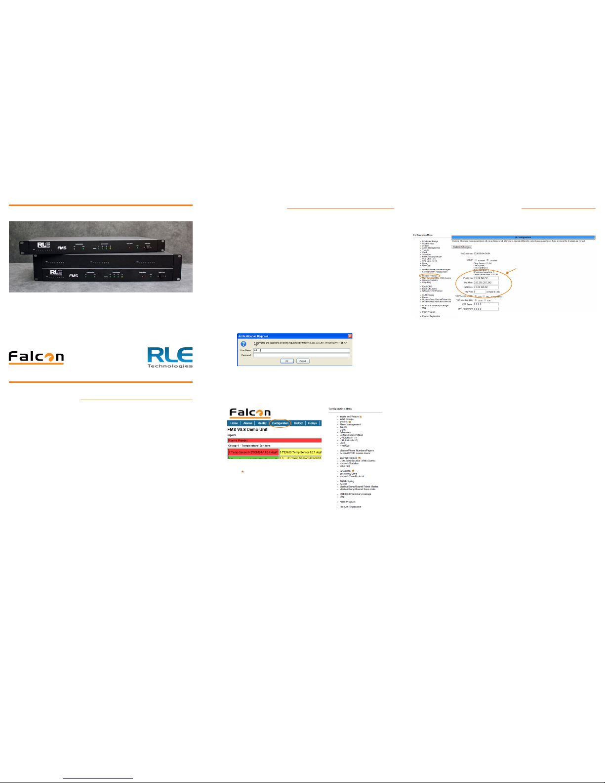
4. Access the FMS through a Web browser by typing the FMS’s default IP address
(10.0.0.188) into the location bar and pressing Enter.
Enter the following:
Default User Name: falcon (case sensitive)
Default Password: (No default password. Leave this eld blank.)
5. From the top bar, select the Conguration Menu link. You will select menu
options from the Conguration Menu for all conguration tasks described in this
guide.
Congure Network Communications
IMPORTANT! Consult your IT administrator before performing these steps.
Click the Internet Protocol link in the Conguration menu to access the IP
Conguration page.
1. Enter the values for IP Address, Net Mask (subnet mask), and Def Route
(default gateway) provided by your IT administrator.
Once you enter the values and click the Submit Changes button, the FMS saves
the changes and reboots. The system status LED on front of the FMS stops
ashing.
2. Reset the computer to its original IP address and subnet mask.
Note: This step might require assistance from your IT administrator.
The computer and the FMS are now both congured to communicate on the
network.
3. Connect the computer and the FMS to the network.
4. From the computer’s Web browser, go to the new IP address of the FMS.
5. When prompted, enter the user name and password to verify network access to
the FMS (as you did in step 4 in the previous section).
If the login window for the FMS does not display:
A. Verify that the cables are rmly attached.
B. Verify that you entered the correct IP address for the FMS.
C. Check for activity on the Link and Active LEDs on the front of the FMS as
follows:
• If the Link LED is off, the FMS is not connected to the network.
Check the cable connections.
• If the Active LED is on solid, too much data is being sent to the
FMS for it to process. Consult your IT administrator.
© Raymond & Lae Engineering, Inc. 2011. All rights reserved. RLE® is a registered trademark and Seahawk™, Falcon™, and Raptor™ are trademarks
of Raymond & Lae Engineering, Inc. The products sold by RLE Technologies, 104 Racquette Dr., Fort Collins, CO 80524 are subject to the limited warranty, limited liability, and other terms and conditions of sale set forth at http://www.rletech.com/.
v2.2
(12/2016)
Prepare for Installation
Consult your IT administrator and determine the following settings for your FMS:
Basic Communications
• IP Address _______________________________________________
• Subnet Mask _____________________________________________
• Default Gateway __________________________________________
Email Notications
• Primary DNS _____________________________________________
• Secondary DNS ___________________________________________
• Mail SMTP Address ________________________________________
• Mail Sender Address _______________________________________
• Mail Recipient Address _____________________________________
ESMTP For Email Authentication
• ESMTP User Name_________________________________________
• ESMTP Password __________________________________________
• Default Gateway __________________________________________
FMS Quick Start Guide
Thank you for purchasing the Falcon FMS. This guide describes how to connect
the FMS to the network, congure inputs and system settings, and set up email
notication. The FMS User Guide, located at rletech.com, contains additional
installation details. Any time you work with printed materials, consult our website
rst to ensure you have the most recent version of those documents.
If you need further assistance, contact RLE Technologies at support@rletech.com.
You will use these items
on the Conguration Menu
to complete the tasks
described in this quick
start guide.
FMS Default Values
IP address: 10.0.0.188
Subnet Mask: 255.255.255.0
Use values provided by
your IT Administrator.
(IP Address or Host Name)
(Up to 8 Recipients)
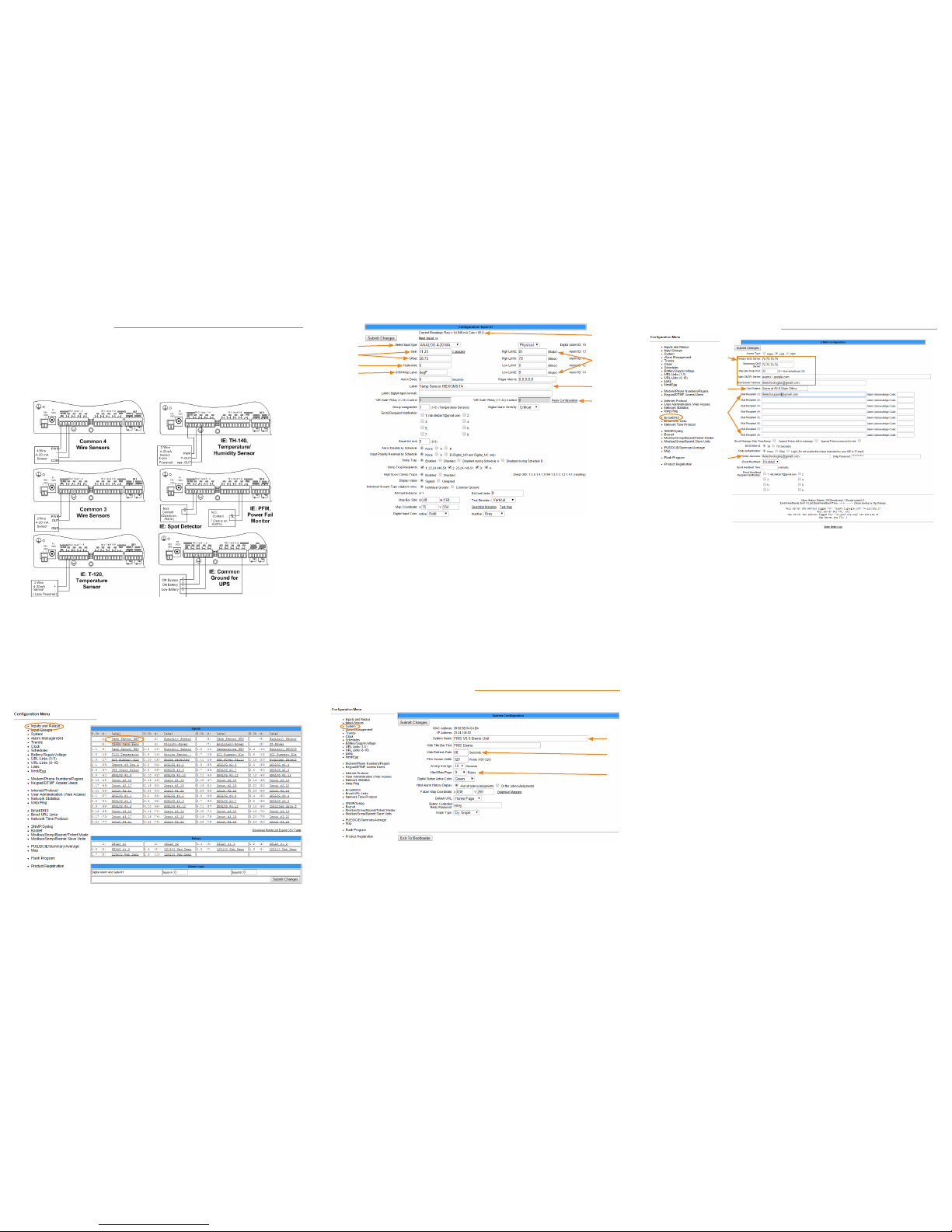
Congure the Inputs
The eight non-isolated universal inputs are connected to TB2 and TB3. Universal
input channels can be individually congured through the FMS to monitor a 4-20mA
signal, a normally open (NO) dry contact relay, or a normally closed (NC) dry
contact relay.
Make the Physical Connections
The following gure shows examples of input wiring:
Once you have wired the inputs, make note of the following:
• Sensor type (analog or digital) connected to each channel
• For each analog sensor - the high and low alarm thresholds.
• For each digital sensor - the non-alarm state: normally open (NO) or normally
closed (NC).
Congure the Inputs
Use the Inputs and Relays page of the conguration menu to congure the inputs.
Click on the underlined label for the input you would like to congure.
A. An input can be Analog 4-20 mA or Digital NO, NC, or Status
B. Applies only to analog inputs. Gain and offset are used by the FMS to
convert temperature, humidity, etc. readings to a 4-20mA signal.
C. Applies only to analog inputs. Hysteresis is the amount the reading of an
alarming input must change before it’s reported as returned to normal.
D. Applies only to analog inputs - use Deg F, Deg C, %RH, Amps, Volts, PSI,
etc. The UoM eld displays on main menu and in alarm notications.
E. The raw reading as reported by the FMS and the calculated value based
on the gain and offset settings.
F. Applies only to Analog inputs. Set the one or two high and low alarm
thresholds to designate the range you would like to monitor.
G. The input label displays on the main menu and in the conguration menu.
H. This link congures corresponding relay output behavior for this input.
Congure System Information
Use the System link on the Conguration menu to congure system information.
A. The system name appears on the FMS main menu and is included as part
of email and pager notications.
B. The rate at which the web pages refresh within the browser. Use a
number greater than 5.
C. Designate the number of points you’ll display on the main menu. Typically
users enter 0 here to display all points.
Congure Email Notication
A. Refer to the information you collected from your IT administrator.
B. Select subject text that you will easily recognize as notication from the
FMS.
C. Enter up to eight email recipients - either individual email addresses or
distribution lists.
D. This information is used for ESMTP email authentication. Refer to the
information you collected from your IT administrator.
Complete the Installation
Once you have completed the tasks in this quick start guide, the FMS can
communicate over the network and monitor the inputs you congured.
Consult the FMS User Guide at http://www.rletech.com for information about
completing these additional tasks:
• System clock settings
• Network time protocol settings
• SNMP/Syslog settings
• Modbus/Telnet settings
• BACnet settings
• User administration
• URL links to IP-addressable devices
• Nest/Egg conguration (for additional FMS appliances that will be monitored by
a central FMS appliance)
• Trends
• Alarm management
• Product registration
A
B
C
D
E
F
G
H
A
B
C
A
B
C
D
 Loading...