

Page 1

FMS USER GUIDE
RLE TECHNOLOGIES
Page 2

©2009 RLE Technologies 10036 Rev. 3.0 (6/2009)
Page 3

FALCON FMS
Page 4

PRODUCT REGISTRATION
Product registration helps RLE Technologies inform owners of:
Product Upgrades
Firmware Enhancements
New Products and Technologies
Special Offers Available Only to Registered Users
Access and submit Product Registration information from the Falcon FMS Configuration Menu.
**Any information provided to RLE Technologies through the registration form will be regarded as confidential. RLE will not
sell or distribute any of the information to third parties. To read our Privacy Policy, please visit our website: rletech.com**
TECHNICAL SUPPORT
Personal assistance is available Monday through Friday, from 8:00 a.m. to 5:00 p.m. MST.
For more information, please download the Product User Guide from the Products/Falcon/FMS
section on our website at www.rletech.com
A request for assistance may be sent to support@rletech.com
Otherwise, please call us directly at: (970) 484-6510 - press “2” for technical support
The following information is located on the bottom of each Falcon FMS unit.
Please have this information available whenever a technical support call is placed:
Product Model Number _____________________________________________________
Product Serial Number _____________________________________________________
Product Manufacture Date ___________________________________________________
.
.
©2009 RLE Technologies 10036 Rev. 3.0 (6/2009)
Page 5

User Guide: Falcon FMS Table of Contents
TABLE OF CONTENTS
Chapter 1: System Overview.........................................................................................................................................1
1-1 Product Description.........................................................................................................................................1
1-2 Front Panel Indicators and Controls................................................................................................................1
1-3 Terminal Block Designations..........................................................................................................................2
1-4 Rear Panel Indicators ......................................................................................................................................3
1-5 SW1 Switch Settings.......................................................................................................................................3
Chapter 2: Getting Started.............................................................................................................................................4
2-1 Installation.......................................................................................................................................................4
2-2 Falcon FMS Wiring......................................................................................................................................... 4
2-2.1 Power Supply and Ground Connections...............................................................................................4
2-2.2 Universal Input Connections ................................................................................................................ 6
2-2.3 Relay 1 and 2 Connections...................................................................................................................8
2-2.4 Keypad Connection ............................................................................................................................10
2-2.5 EIA232 COM2 Connection................................................................................................................10
2-2.6 RJ11 Phone Line Connection .............................................................................................................10
2-2.7 RJ45 Ethernet Connection..................................................................................................................11
2-2.8 Modbus EIA485 Connections ............................................................................................................12
2-2.9 Modbus EIA232 Connections ............................................................................................................12
2-2.10 Expansion Card A Connections..........................................................................................................13
2-2.11 Expansion Card C Connections..........................................................................................................15
2-3 Communication .............................................................................................................................................17
2-4 Set The FMS IP Address...............................................................................................................................17
2-4.1 Set the IP Address Using the ARP and PING Commands ................................................................. 17
2-4.1.1 Obtain the Ethernet Address (MAC Address) .........................................................................17
2-4.1.2 Use the ARP Command...........................................................................................................17
2-4.1.3 Use the PING Command ......................................................................................................... 17
2-4.1.4 Troubleshooting the ARP/PING Commands...........................................................................18
2-4.2 Set the IP Address Using a Web Browser ..........................................................................................18
2-4.3 Set the FMS IP Address using an EIA232 Connection ......................................................................19
Chapter 3: FMS Configuration....................................................................................................................................20
3-1 FMS WEB Interface Overview.....................................................................................................................20
3-2 Main Menu .................................................................................................................................................... 21
3-3 Input and Relay .............................................................................................................................................22
3-3.1 Main Board Input Configuration (Channels 1-8) ...............................................................................23
3-3.2 Expansion Card “A” Input Configuration ..........................................................................................27
www.rletech.com 970 484-6510 i
Page 6

Table of Contents User Guide: Falcon FMS
3-3.3 Expansion Card “C” Input Configuration..........................................................................................28
3-3.3.1 Internal Temperature and Internal Humidity Configuration ................................................... 29
3-3.4 Relay Configuration .......................................................................................................................... 29
3-4 System .......................................................................................................................................................... 31
3-4.1 IP Configuration Menu ...................................................................................................................... 33
3-5 Network Statistics......................................................................................................................................... 34
3-6 ICMP Ping .................................................................................................................................................... 34
3-7 BACnet ......................................................................................................................................................... 35
3-8 User Administration (Web Access) .............................................................................................................. 35
3-9 Web User Access Log .................................................................................................................................. 36
3-10 SNMP/Syslog.............................................................................................................................................. 36
3-11 URL Links (1-5).......................................................................................................................................... 38
3-12 URL Links (6-10)........................................................................................................................................ 38
3-13 Links............................................................................................................................................................ 39
3-14 Nest/Egg...................................................................................................................................................... 39
3-14.1 Falcon Nest Configuration................................................................................................................. 39
3-14.2 Egg Configuration ............................................................................................................................. 40
3-15 Modem ........................................................................................................................................................ 40
3-15.1 Configure Phone Numbers ................................................................................................................ 42
3-15.2 Configure Phone Number 16 (PPP)................................................................................................... 44
3-16 Alarm Management..................................................................................................................................... 44
3-17 Keypad/DTMF Access Users...................................................................................................................... 45
3-18 Schedules..................................................................................................................................................... 46
3-19 Battery......................................................................................................................................................... 46
3-20 Clock. .......................................................................................................................................................... 47
3-21 Email/DNS.................................................................................................................................................. 48
3-22 Network Time Protocol (NTP).................................................................................................................... 49
3-23 Modbus/Com Port 1 .................................................................................................................................... 49
3-24 Modbus / Slave Units .................................................................................................................................. 50
3-25 Flash Program ............................................................................................................................................. 52
3-26 Product Registration.................................................................................................................................... 53
Chapter 4: FMS Web Interface................................................................................................................................... 54
4-1 Main Menu/ Home Page............................................................................................................................... 54
4-2 Keypad (DTMF) Access History.................................................................................................................. 55
4-3 Alarm History............................................................................................................................................... 55
4-4 Event History................................................................................................................................................ 57
4-5 Digital Status History ................................................................................................................................... 57
ii 970 484-6510 www.rletech.com
Page 7

User Guide: Falcon FMS Table of Contents
4-6 Data History ..................................................................................................................................................58
4-6.1 Minute, Hour, and Day View .............................................................................................................59
4-6.2 Data History Text Downloads............................................................................................................59
4-6.2.1 Daily, Hourly, Minute..............................................................................................................60
4-6.2.2 Alarm History Text (alarmhistory.txt).....................................................................................60
4-7 Identity ..........................................................................................................................................................61
4-8 URL Links..................................................................................................................................................... 61
4-9 Relay Status...................................................................................................................................................62
4-10 Relay Control...............................................................................................................................................62
4-11 Configuration ...............................................................................................................................................63
Chapter 5: Communication..........................................................................................................................................64
5-1 Modbus.......................................................................................................................................................... 64
5-2 Hardware Connections ..................................................................................................................................64
5-2.1 EIA232 ...............................................................................................................................................64
5-2.2 EIA485 ...............................................................................................................................................65
5-3 Modbus/COM1 Configuration (Modbus MASTER & Slave) ......................................................................66
5-3.1 Modbus Master Poll Data Log ...........................................................................................................69
5-3.2 Modbus Slave Register Display Log..................................................................................................69
5-3.3 Modbus Packet Log............................................................................................................................ 70
5-3.4 Reset Modbus Port .............................................................................................................................71
5-4 Configuring Inputs and relays for Slave Units (Modbus & BACnet) ...........................................................71
5-5 Modbus / Slave Units Configuration – Modbus Generic (typical)................................................................73
5-5.1 Unit Number Links.............................................................................................................................73
5-5.2 Modbus Register Links ......................................................................................................................74
5-5.3 Read/Preset Single Register ...............................................................................................................76
5-6 Modbus / Slave Units Configuration – Modbus Master BCM – 4 ................................................................76
5-6.1 Unit Number Links.............................................................................................................................77
5-6.2 Modbus Register Links ......................................................................................................................78
5-6.2.1 CB# Links................................................................................................................................ 78
5-7 Modbus / Slave Units Configuration – Modbus Master BCM - 16...............................................................79
5-8 Additonal Modbus Information.....................................................................................................................80
5-8.1 Slave Register Map ............................................................................................................................80
5-8.2 Alarm Bit Map (Reg 40201-40306) ...................................................................................................81
5-8.3 Configuration Codes (Reg 40401-40504) ..........................................................................................81
5-9 BACnet.......................................................................................................................................................... 81
5-9.1 BACnet /Slave Units Configuration...................................................................................................82
5-9.2 Unit Number Links.............................................................................................................................83
www.rletech.com 970 484-6510 iii
Page 8

Table of Contents User Guide: Falcon FMS
5-9.3 BACnet Instance Register Links ....................................................................................................... 83
5-10 TELnet............................................................................................................................................... 84
5-10.1 Hardware Connections ...................................................................................................................... 84
5-10.2 Telnet/COM1 Configuration ............................................................................................................. 85
5-10.3 Telnet Communication ...................................................................................................................... 86
Chapter 6: EIA232 Interface....................................................................................................................................... 88
6-1 Unit Start Up ................................................................................................................................................ 88
6-2 Flash Executable Code ................................................................................................................................. 88
6-3 Main Menu ................................................................................................................................................... 88
6-3.1 Main Configuration Menu - SC......................................................................................................... 90
6-3.1.1 IP Configuration Menu ...........................................................................................................91
Chapter 7: Remote Access.......................................................................................................................................... 93
7-1 Remote Access Configuration ...................................................................................................................... 93
Chapter 8: Point-to-Point Protocol.............................................................................................................................. 94
8-1 Configuring the FMS.................................................................................................................................... 94
8-2 Configuring the PC....................................................................................................................................... 94
Chapter 9: Upgrading Firmware, Loading & Saving Configuration Data .................................................................. 95
9-1 Updating FMS Firmware.............................................................................................................................. 95
9-1.1 Updating FMS Firmware via TFTP Client ........................................................................................ 95
9-1.2 Updating FMS Firmware via the EIA232 COM2 Port (X-Modem).................................................. 96
9-2 Loading/Saving fms Configuration data ...................................................................................................... 97
9-2.1 Saving Configuration Data via TFTP Client ..................................................................................... 97
9-2.2 Saving Configuration Data via EIA232 COM2 Port (X-Modem)..................................................... 97
9-2.3 Loading Configuration Data via TFTP Client ................................................................................... 99
9-2.4 Loading Configuration Data via EIA232 COM2 Port (X-Modem)................................................... 99
APPENDIX A: FMS Expansion Cards .................................................................................................................... 100
A-1 Expansion Card Descriptions ..................................................................................................................... 100
A-2 Expansion Card Installation ....................................................................................................................... 100
A-2.1 Installing an Expansion Card into a One Rack Unit FMS ............................................................... 100
A-2.2 Installing an Expansion Card into a Two Rack Unit FMS .............................................................. 102
A-3 Converting Current Input Channels to Voltage Input Channels on Expansion Card A.............................. 105
APPENDIX B: Analog Averaging........................................................................................................................... 106
B-1 Analog Averaging Overview...................................................................................................................... 106
B-2 How Analog Averaging Affects Values..................................................................................................... 106
APPENDIX C: Analog Input 4-20mA Reference Chart .......................................................................................... 107
APPENDIX D: FMS Accessories Wiring ................................................................................................................ 109
APPENDIX E: Alarm ID Reference Tables............................................................................................................. 115
iv 970 484-6510 www.rletech.com
Page 9

User Guide: Falcon FMS Table of Contents
E-1 Analog Tables .............................................................................................................................................115
E-2 Digital Tables .............................................................................................................................................. 118
APPENDIX F: FMS Slot Designations.....................................................................................................................120
F-1 Input Slot Designation Table.......................................................................................................................120
F-2 Output Slot Designation Table....................................................................................................................123
APPENDIX G: Relay Control Logic ........................................................................................................................125
APPENDIX H: Expansion Card B............................................................................................................................127
H-1.1 Expansion Card B Connections........................................................................................................ 127
APPENDIX I: Technical Specifications ...................................................................................................................129
www.rletech.com 970 484-6510 v
Page 10

List of Figures and Tables User Guide: Falcon FMS
LIST OF FIGURES AND TABLES
Figure 1-1: Terminal Block Designations..................................................................................................................... 2
Figure 1-2: Rear Panel Indicators ................................................................................................................................. 3
Figure 1-3: SW1 Switch is in the down position (ON) and SW2 switch is in the up position (OFF)........................... 3
Figure 2-1: 24VDC Power Supply Connection ............................................................................................................ 4
Figure 2-2: 48VDC Power Supply Connection ............................................................................................................ 5
Figure 2-3: Universal Input Wiring Examples.............................................................................................................. 7
Figure 2-4: Dry Contact Iputs with Common Ground.................................................................................................. 8
Figure 2-5: Relay Output Wiring Examples ................................................................................................................. 9
Figure 2-6: Keypad Wiring......................................................................................................................................... 10
Figure 2-7: EIA232 COM2 Connection ..................................................................................................................... 10
Figure 2-8: FMS Ethernet Connection to a PC using a Crossover Cable ................................................................... 11
Figure 2-9: FMS Ethernet Connection to a PC on a Sub-Net ..................................................................................... 11
Figure 2-10: FMS EIA485 Connection....................................................................................................................... 12
Figure 2-11: FMS EIA232 Connection to a DCE or DTE Device.............................................................................. 13
Figure 2-12: Expansion Card A I/O Terminals........................................................................................................... 14
Figure 2-13: Analog Input Wiring for Expansion Card A .......................................................................................... 14
Figure 2-14: Dry Contact Inputs with Individual Ground and Relay Outputs, Card A .............................................. 15
Figure 2-15: Expansion Card C I/O Terminals........................................................................................................... 15
Figure 2-16: Typical Wiring for Expansion Card C ................................................................................................... 16
Figure 2-17: Falcon FMS Expansion Cards A & C................................................................................................... 16
Figure 3-1: Initial Loggin for the FMS....................................................................................................................... 21
Figure 3-2: Main Menu/Homepage of the FMS ......................................................................................................... 21
Figure 3-3: Sample FMS Configuration Main Menu.................................................................................................. 22
Figure 3-4: Sample FMS Input/Output Configuration Menu...................................................................................... 22
Figure 3-5: Sample FMS Main Board Input Configuration........................................................................................ 23
Figure 3-6: Gain and Offset Calculator ...................................................................................................................... 24
Figure 3-7: NO/NC Wiring Example......................................................................................................................... 27
Figure 3-8: Expansion Card “A” Input Card .............................................................................................................. 28
Figure 3-9: Sample of Falcon FMS Configuration Main Menu.................................................................................. 28
Figure 3-10: Sample FMS Relay Configuration......................................................................................................... 29
Figure 3-11: Sample FMS Keypad/Relay Configuration............................................................................................ 30
Figure 3-12: Sample FMS System Configuration....................................................................................................... 31
Figure 3-13: Sample FMS PDA Width Configuration ............................................................................................... 32
Figure 3-14: Sample FMS IP Configuration Menu .................................................................................................... 33
Figure 3-15: Sample FMS Network Status Page ........................................................................................................ 34
vi 970 484-6510 www.rletech.com
Page 11

User Guide: Falcon FMS List of Figures and Tables
Figure 3-16: Sample FMS ICMP Ping Page................................................................................................................34
Figure 3-17: Sample FMS BACnet Configuration......................................................................................................35
Figure 3-18: Sample FMS Web Access Configuration ...............................................................................................35
Figure 3-19: Sample FMS Web User Access Log.......................................................................................................36
Figure 3-20: Sample FMS SNMP Configuration ........................................................................................................36
Figure 3-21: Sample FMS URL (1-5) Links Configuration........................................................................................38
Figure 3-22: Sample FMS URL (6-10) Links Configuration......................................................................................38
Figure 3-23: Links Configuration Page.......................................................................................................................39
Figure 3-24: Sample FMS Nest Egg Page................................................................................................................... 39
Figure 3-25: Sample FMS Nest Configuration............................................................................................................40
Figure 3-26: Sample FMS Egg Configuration.............................................................................................................40
Figure 3-27: Sample FMS Modem Configuration.......................................................................................................41
Figure 3-28: Sample FMS Phone Number Configuration...........................................................................................42
Figure 3-29: Sample FMS Phone Number 16 (PPP) Configuration............................................................................44
Figure 3-30: Sample FMS Alarm Settings Menu........................................................................................................44
Figure 3-31: Sample FMS URL (6-10) Links Configuration......................................................................................45
Figure 3-32: Sample FMS Schedule Configuration ....................................................................................................46
Figure 3-33: Sample FMS Battery Page......................................................................................................................46
Figure 3-34: Sample FMS Clock Configuration..........................................................................................................47
Figure 3-35: Sample FMS E-mail Configuration ........................................................................................................48
Figure 3-36: Sample FMS Network Time Protocol (NTP) Configuration .................................................................. 49
Figure 3-37: Sample FMS Modbus/Com1 Configuration ...........................................................................................50
Figure 3-38: Sample Modbus Generic Slave Unit Configuration (most common configuration) ...............................51
Figure 3-39: Sample Modbus BCM 16 Unit Configuration Webpage........................................................................51
Figure 3-40: Sample Modbus BCM 4 Units Configuration Webpage.........................................................................52
Figure 3-41: Sample FMS Schedule Configuration ....................................................................................................52
Figure 3-42: Product Registration Webpage ...............................................................................................................53
Figure 4-1: An example of what a configured FMS could look like. ..........................................................................54
Table 4-1: Color Definitions........................................................................................................................................54
Figure 4-2: Keypad Access History View...................................................................................................................55
Figure 4-3: Sample FMS Alarm History Page ............................................................................................................56
Figure 4-4: Sample FMS Event History Page .............................................................................................................57
Figure 4-5: Sample FMS Event Digital Status History Page.......................................................................................57
Figure 4-6: Sample FMS Data History Page...............................................................................................................58
Figure 4-7: Sample FMS Minute, Hour, and Day Page...............................................................................................59
Figure 4-8: Sample FMS Data History Text Downloads Page.................................................................................... 59
Figure 4-9: Sample FMS Index of Page ......................................................................................................................60
www.rletech.com 970 484-6510 vii
Page 12

List of Figures and Tables User Guide: Falcon FMS
Figure 4-10: Sample FMS Alarm History Text Page.................................................................................................. 60
Figure 4-11: Sample of Falcon FMS Identity ............................................................................................................. 61
Figure 4-12: Sample FMS Still images from IP Cameras........................................................................................... 61
Figure 4-13: Sample FMS Relay Display Status ........................................................................................................ 62
Figure 4-14: Sample FMS Relay Control Page .......................................................................................................... 62
Figure 4-15: Sample FMS Configuration Page........................................................................................................... 63
Figure 5-1: FMS Modbus EIA232 Connection to an EIA232 DCE Device .............................................................. 65
Figure 5-2: FMS Modbus EIA232 Connection to an EIA232 DTE Device .............................................................. 65
Figure 5-3: EIA485 Wiring Connections................................................................................................................... 65
Figure 5-4: EIA485 Wiring to RLE/Veris BCMs (Branch Circuit Monitors) ........................................................... 66
Figure 5-5: Sample FMS Modbus/Com1 Configuration with EXP-MBCS Option installed ..................................... 67
Figure 5-6: Modbus / COM Port 1 link without the EXP-MBCS Option Installed .................................................... 67
Figure 5-7: Modbus Master Poll Data Log................................................................................................................. 69
Figure 5-8: Modbus Slave Register Display Log........................................................................................................ 70
Figure 5-9: Modbus Packet Log ................................................................................................................................. 71
Figure 5-10: Modbus Rest Port Confirmation ........................................................................................................... 71
Figure 5-11: Input and Relay Configuration Menu..................................................................................................... 71
Figure 5-12: Individual Input Configuration Screen................................................................................................... 72
Figure 5-13: Modbus Slave Unit Configuration ......................................................................................................... 73
Figure 5-14: Sample Modbus Slave Unit.................................................................................................................... 74
Figure 5-15: Modbus Register Configuration Menu................................................................................................... 75
Figure 5-16: Individual Modbus Configuration Screen.............................................................................................. 75
Figure 5-17: Return to Configuration Menu............................................................................................................... 76
Figure 5-18: Modbus BCM Unit Configuration ......................................................................................................... 77
Figure 5-19: Individual Slave Configuration Screen .................................................................................................. 77
Figure 5-20: Modbus Registers Screen....................................................................................................................... 78
Figure 5-21: Circuit Breaker Configurations for Individual BCM’s .......................................................................... 79
Figure 5-22: Modbus BCM Unit Configuration Page................................................................................................. 80
Table 5-1: Slave Register Map ................................................................................................................................... 80
Figure 5-23: BACnet Configuration Screen ............................................................................................................... 81
Figure 5-24: BACnet /Slave Unit Configuration ........................................................................................................ 83
Figure 5-25: Individual Slave Unit Configuration Screen.......................................................................................... 83
Figure 5-26: BACnet Configuration Registers Screen................................................................................................ 84
Figure 5-27: BACnet Instance Configuration............................................................................................................. 84
Figure 5-28: FMS connection to a EIA232 device. .................................................................................................... 85
Figure 5-29: Telnet/Com1Configuration Page ........................................................................................................... 85
Figure 5-30: Telnet Communication showing a FMS IP address of 10.0.0.108 accessing port 3201. ....................... 86
viii 970 484-6510 www.rletech.com
Page 13

User Guide: Falcon FMS List of Figures and Tables
Figure 5-31: Example of Telnet connection through port 3201 at 9600 baud, 8 data bits, no parity, and 1 stop bit... 86
Figure 5-32: Example of Telnet Menu (device–specific)............................................................................................87
Table 6-1: EIA232 Main Menu ................................................................................................................................... 89
Table 6-2: Main Configuration Menu Options (SC) ...................................................................................................90
Table 6-3: IP Configuration Menu ..............................................................................................................................91
Figure 9-1: Correct COM1 Port Settings.....................................................................................................................98
Figure 9-2: COM1 Port Settings..................................................................................................................................98
Table A-1: Expansion Card Descriptions..................................................................................................................100
Figure A-1: Expansion Card SW2 Dip Switch..........................................................................................................101
Figure A-2: Expansion Card Mounting in a One Rack Unit .....................................................................................101
Figure A-3: Opening and Closing a Two Rack Unit .................................................................................................103
Figure A-4: Expansion Card Ribbon Cable Placement in a Two Rack Unit............................................................. 103
Figure A-5: Expansion Card Mounting in a Two Rack Unit.....................................................................................104
Figure A-6: Expansion Card Final Placement in a Two Rack Unit...........................................................................104
Figure A-7: Expansion Card Final Placement in Two Rack Enclosure.....................................................................105
Figure A-8: Expansion Card Final Placement in Two Rack Enclosure.....................................................................105
Table C-1: Analog Input 4-20mA Reference Chart...................................................................................................107
Figure D-1: T120 & T120D Temperature Sensors....................................................................................................109
Figure D-2: TH140 & TH140D Temperature/Humidity Sensors..............................................................................109
Figure D-3: Dwyer Temperature/Humidity Sensor...................................................................................................110
Figure D-4: BAPI Temperature/Humidity Sensor.....................................................................................................110
Figure D-5: HD150, HD150-2, CM150-2, & HG150-2 Gas Sensors.......................................................................111
Figure D-6: RD150-F2, RD150-2 & RD150-R Refrigerant Detectors.....................................................................111
Figure D-7: PFM Power Fail Monitor......................................................................................................................112
Figure D-8: SeaHawk LD5100 / LD5000 Distance Read Water Leak Detection System (Dry Contact).................112
Figure D-9: SeaHawk LD5100 / LD5000 Distance Read Water Leak Detection System (4-20mA)....................... 113
Figure D-10: SeaHawk LD1000, LD300, and LDRA6 Zone Water Leak Detection Systems.................................114
Table E-1: Analog Alarm ID Reference Tables ........................................................................................................115
Table E-2: Digital Alarm ID Reference Tables.........................................................................................................118
Table F-1: Input Slot Designation Table ................................................................................................................... 120
Table F-2: Output (Relays) Slot Designation Table ..................................................................................................123
Figure G-1: FMS EM Relay Control Logic Diagram................................................................................................125
Figure H-1: Expansion Card B I/O Terminals...........................................................................................................127
Figure H-2: Typical Wiring for Expansion Card B...................................................................................................127
Figure H-3: Expansion Card B ..................................................................................................................................128
www.rletech.com 970 484-6510 ix
Page 14

Page 15
User Guide: Falcon FMS System Overview
CHAPTER 1: SYSTEM OVERVIEW
1-1 PRODUCT DESCRIPTION
The Falcon Monitoring System (FMS) is a comprehensive system which provides additional equipment
protection by monitoring critical operating parameters in enterprises, remote network facilities,
communication rooms, remote and unmanned facilities, and critical support systems. The FMS is a stand
alone system. It operates via embedded “firmware” that handles all data collection, alarm reporting, and
multiple concurrent communication mediums.
The FMS typically monitors analog and dry contact outputs from devices such as temperature sensors,
humidity sensors, gas detectors, smoke detectors, fire suppression systems, surveillance products (e.g., IP
cameras), leak detection systems, power monitoring systems, uninterruptible power supplies (UPSs), power
distribution units (PDUs), generators, DC power plants, commercial power, HVAC units, ATS, TVSSs,
and access keypads.
The FMS performs internal diagnostics that check the Flash Program code, serial ports, RAM, non-volatile
RAM, real-time clock, internal power supplies, relay drivers, analog to digital converter (ADC), and
modem. During operation, the FMS monitors its status and uses several LED indicators to report its
condition.
The FMS embedded firmware enables system configuration, I/O setup, status inquiries, alarm reports, data
logs, and troubleshooting. The FMS is menu driven and operates with any Web browser, ASCII terminal,
or terminal emulation application (e.g., HyperTerminal).
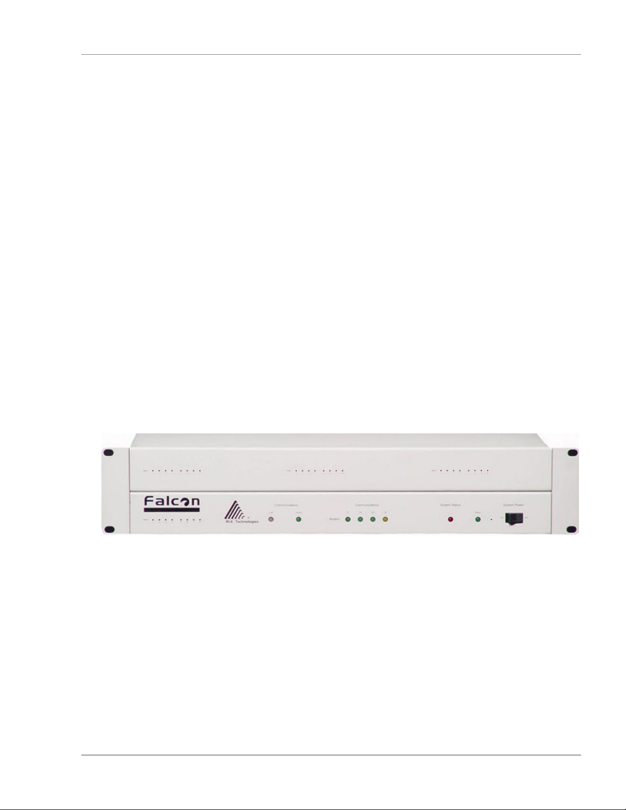
1-2 FRONT PANEL INDICATORS AND CONTROLS
Expansion Card Relay Status LEDs
Green (On) if the relay is active—for Expansion Card A only.
Network LEDs – Two Network Status LEDs
Link - Green if network link is established. Red if there is no connection.
Active – Green (On) if transmitting or receiving data.
Communications LEDs – Four Modem Status LEDs
TX – Green (On) if information is being transmitted.
RX – Green (On) if information is being received.
OH – Green (On) if the Modem detects a dial tone (off hook).
CD - Yellow (On) if a carrier is detected.
www.rletech.com 970 484-6510 1
Page 16
System Overview User Guide: Falcon FMS
System Status LED
Flashes Red ten times per second during the initial boot up of the FMS, which is approximately
45 seconds. If the initial boot up fails, the LED continues to flash. This indicates a condition that
requires service; users must contact RLE for more information. After the boot up, this LED turns
off if no alarms are present, or turns solid if the unit is in an alarm condition.
Power LED – Green (On) if power is on.
System Power Switch – Used to turn power to the unit on and off.
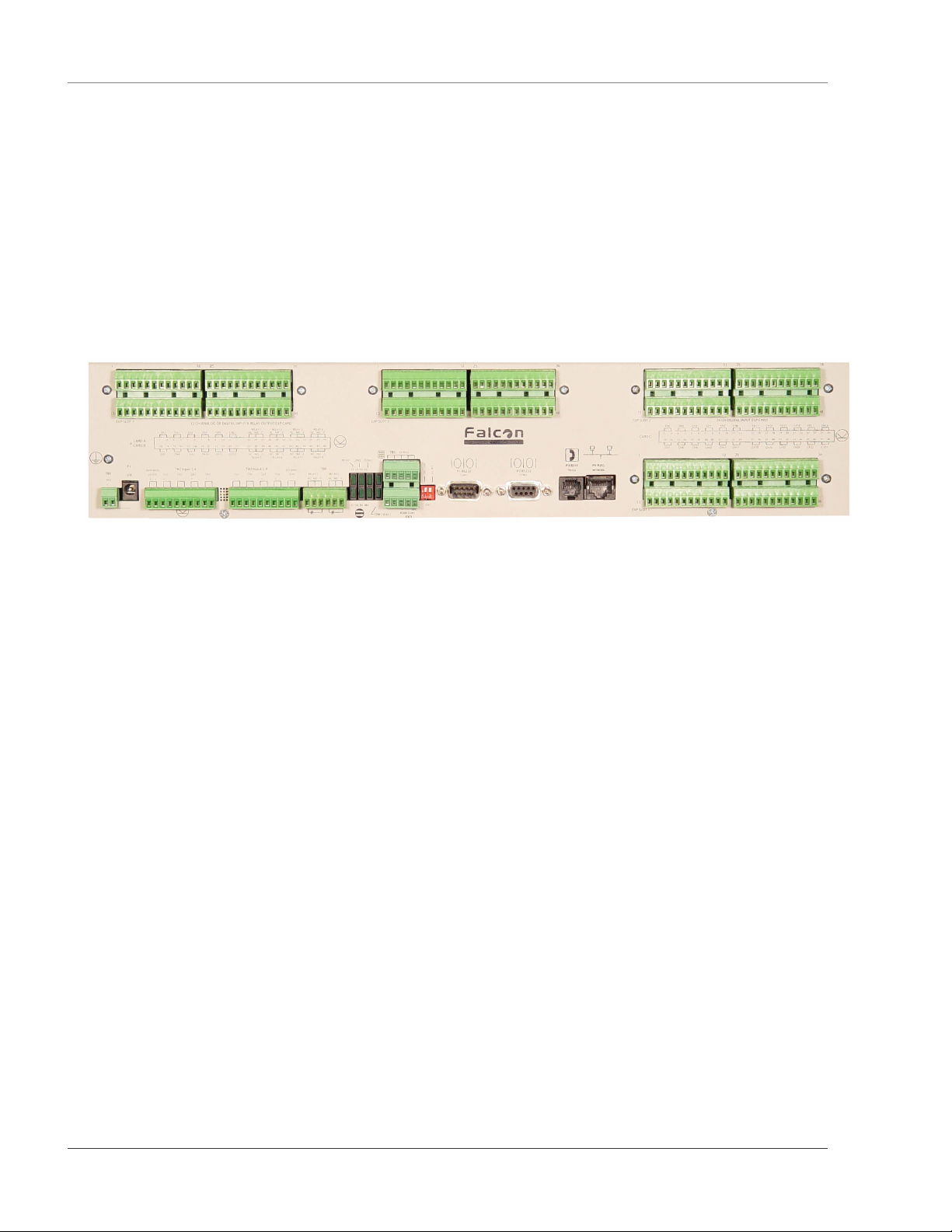
1-3 TERMINAL BLOCK DESIGNATIONS
Figure 1-1: Terminal Block Designations
TB1-1 (+) Input for 24 or 48VDC
(optional) power
TB1-2 (-) Input for 24 or 48VDC (optional) power
P1 24VDC wall adapter input (center +)
(not available with 48VDC version)
TB2-1 24VDC positive (+) external output
(power for sensors)
TB2-2 24VDC positive (+) external output
(power for sensors)
TB2-3 Channel 1 positive (+)
TB2-4 Channel 1 negative (-)
TB2-5 Channel 2 positive (+)
TB2-6 Channel 2 negative (-)
TB2-7 Channel 3 positive (+)
TB2-8 Channel 3 negative (-)
TB2-9 Channel 4 positive (+)
TB2-10 Channel 4 negative (-)
TB3-1 Channel 5 positive (+)
TB3-2 Channel 5 negative (-)
TB3-3 Channel 6 positive (+)
TB3-4 Channel 6 negative (-)
TB3-5 Channel 7 positive (+)
TB3-6 Channel 7 negative (-)
TB3-7 Channel 8 positive (+)
TB3-8 Channel 8 negative (-)
TB3-9 24VDC ground external output
(power for sensors)
TB3-10 24VDC ground external output
(power for sensors)
TB4-1 Relay 1 normally closed (NC)
TB4-2 Relay 1 normally open (NO)
TB4-3 Relay 1 common (C)
TB4-4 Relay 2 normally closed (NC)
TB4-5 Relay 2 normally open (NO)
TB4-6 Relay 2 common (C)
TB5-1 Keypad column 1
TB5-2 Keypad column 2
TB5-3 Keypad column 3
TB5-4 Keypad row 1
TB5-5 Keypad row 2
TB5-6 Keypad row 3
TB5-7 Keypad row 4
TB5-8 COM1 EIA485 positive (+)
(configurable)
TB5-9 COM1 EIA485 negative (-)
(configurable)
TB5-10 EIA485 ground
SW1-1 Unit EIA485 termination switch
SW1-2 Reserved for future use.
P2 COM1 EIA232 male DB9 pin
connector (configurable)
P3 COM2 EIA232 female DB9 pin
connector - craft port
P4 RJ-11 telephone line connector
P5 RJ45 Ethernet 10BaseT connector
2 970 484-6510 www.rletech.com
Page 17
User Guide: Falcon FMS System Overview
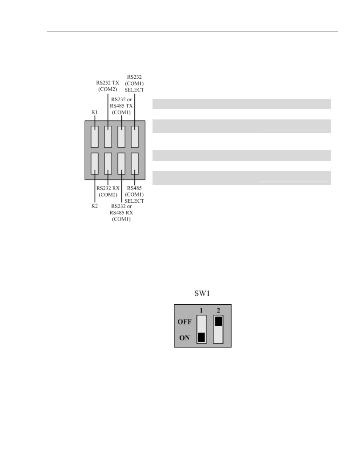
1-4 REAR PANEL INDICATORS
The rear panel of the FMS houses a series of green LEDs. The chart below tracks indicator status when the
corresponding green LED is illuminated:
Status Indicator
K1 (Output Relay) Relay is energized.
EIA232 TX (COM2) Interface Data is being transmitted.
EIA232 or EIA485 TX (COM1)
Interface
EIA232 (COM1) Select Interface EIA232 selected (P2)
K2 (Output Relay) Relay is energized.
EIA232 RX (COM2) Interface Data is being received.
EIA232 or EIA485 RX (COM1)
Interface
EIA485 (COM1) Select Interface EIA485 selected (TB5)
Data is being transmitted.
Data is being received.
1-5 SW1 SWITCH SETTINGS
SW1-1: EIA485 Termination switch should be in the down position (ON) if the FMS is an end
device on an EIA485 network.
SW1-2: Reserved for future use.
Figure 1-3: SW1 Switch is in the down position (ON) and SW2 switch is in the up position (OFF)
Figure 1-2: Rear Panel Indicators
www.rletech.com 970 484-6510 3
Page 18
Getting Started User Guide: Falcon FMS
CHAPTER 2: GETTING STARTED
In order to get the FMS working, users must install the unit, wire and connect the power, and set the IP
address. Any accessories for the FMS should also be connected at this time (e.g., keypad connection,
Modbus connections, Expansion Cards, etc.)
2-1 INSTALLATION
The Falcon FMS comes in a 19 inch (.48m) rack mount enclosure. Install the FMS in the rack. Use the
proper anchoring method to mount the unit securely. Supply either 24VDC (standard) or 48VDC (optional)
to the unit.
WARNING!!
Units have different model numbers. Before applying power to the unit, verify the
model number and power rating located on the back of the unit. The voltage
indicator is the last number on the unit model number. The FMS will either be a
24VDC or a 48VDC.
2-2 FALCON FMS WIRING
RLE Technologies recommends an 18AWG stranded copper wire for connection from each monitored
point to a terminal block (TB) connection on the FMS. RLE recommends no more than 500 feet (152.4m)
of wire at this specification. If longer runs are needed, please contact RLE Technologies for application
guidance. Shielded twisted pair wiring is recommended for analog signal transmitters being wired outside
of conduit runs and dropped ceiling applications.
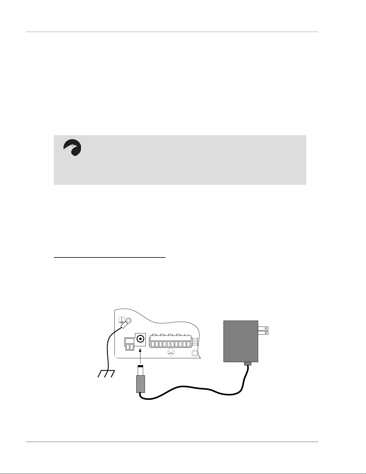
2-2.1 Power Supply and Ground Connections
Connect an 18AWG ground wire from the ground terminal to a suitable earth ground. For 24VDC model
FMS, plug the wall adapter into P1 and a UPS outlet as shown below. The wall adapter has a 5 foot
(1.524m) power cord. RLE Technologies recommends powering the FMS from a UPS supply to allow the
FMS to send alarm notification during a power outage.
P1
EXTERNAL
TB1
VDC
+ -
VDC
24VDC
+ +
TB2 Input 1-4
Ch1
+ -
Ch2
Ch3
Ch4
+ -
+ -
+ -
Figure 2-1: 24VDC Power Supply Connection
4 970 484-6510 www.rletech.com
Page 19

User Guide: Falcon FMS Getting Started
For a 48VDC model FMS, connect a 48VDC supply through a circuit breaker to TB1 as shown below. In
telecommunications applications, the 48VDC supply is typically connected to the 48VDC battery system
through a DC distribution panel.
TB1
VDC
+ -
P1
VDC
EXTERNAL
24VDC
+ +
TB2 Input 1-4
Ch1
Ch2
+ -
+ -
Ch3
+ -
Ch4
+ -
-
48VDC
+
Figure 2-2: 48VDC Power Supply Connection
www.rletech.com 970 484-6510 5
Page 20

Getting Started User Guide: Falcon FMS
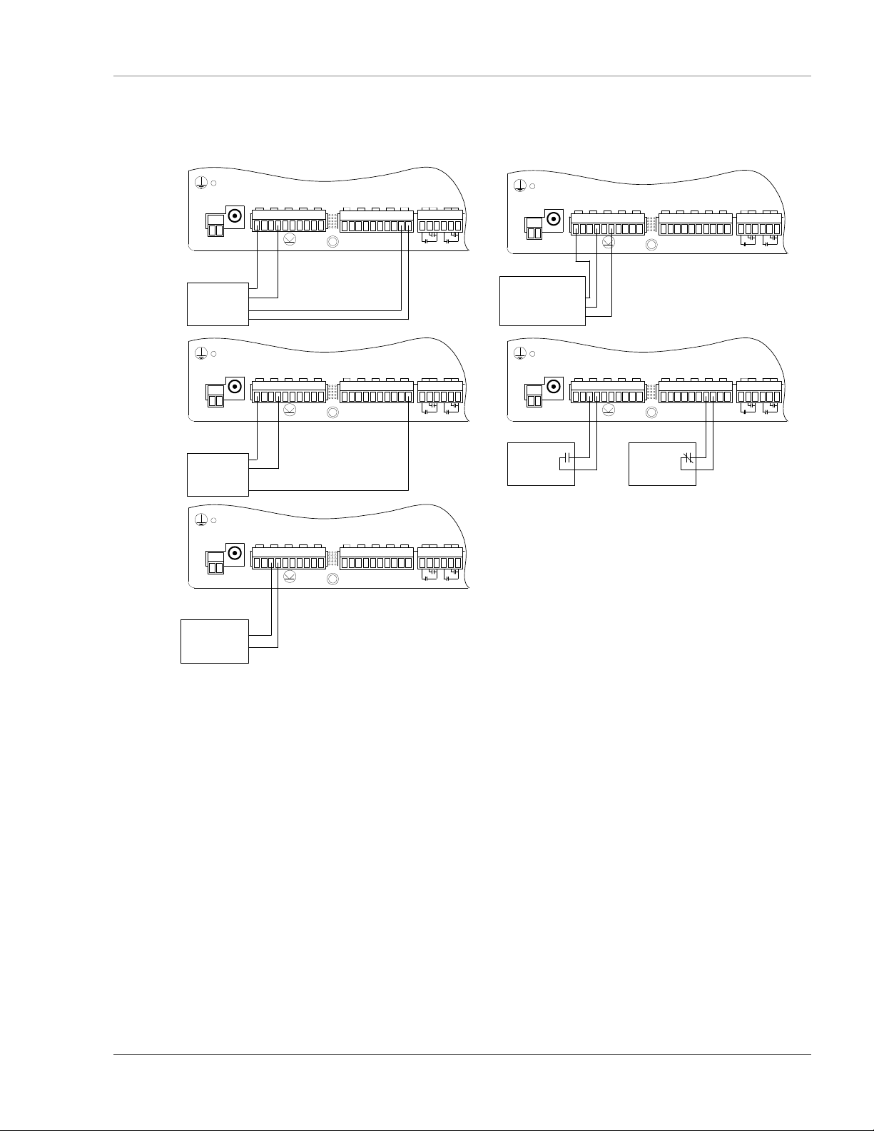
2-2.2 Universal Input Connections
The eight non-isolated universal inputs are connected to TB2 and TB3. Universal input channels can be
individually configured through the FMS to monitor a 4-20mA signal, a Normally Open (NO) dry contact,
or a Normally Closed (NC) dry contact; see
Figure 2-3 for examples of typical sensor wiring. Refer to APPENDIX D: FMS Accessories Wiring on
page 109 for further details on wiring other RLE accessory sensors.
Some temperature and humidity sensors have internal jumper settings that may be used to select sensor
range and output voltage or current. Jumper settings should be set before power is applied to the
equipment. The sensor range (50-95°F, 22-122°F, etc.) should be documented at this time. The sensor
range is required to determine the gain and offset settings when configuring the input through software.
NOTE:
The Falcon has 24VDC available (TB2-1, TB2-2 +24VDC, TB3-9, TB3-10 24VDC
comm.) to power external sensors. The 24VDC external supply is internally fused at
300mA.
6 970 484-6510 www.rletech.com
Page 21
User Guide: Falcon FMS Getting Started
P1
4 Wire
4-20mA
Sensor
TB1
VDC
TB2 Input 1-4
EXTERNAL
VDC
24VDC
Ch1
Ch2
Ch3
+ +
+ -
+ -
+ -
PWR
+
-
COM
+ -
TB3 Input 5-8
EXTERNAL
TB4
Ch5
Ch4
+ -
Ch6
+ -
+ -
GND
Ch7
Ch8
RELAY 1
RELAY 2
- -
NC NO C
+ -
+ -
NC NO C
2 Wire
4-20mA
Sensor
(Loop
Powered)
P1
TB1
VDC
VDC
+ -
Temperature/
Humidity Sensor
T-OUT
RH-OUT
EXTERNAL
PWR
24VDC
+ +
TB2 Input 1-4
Ch1
Ch2
+ -
+ -
TB3 Input 5-8
EXTERNAL
TB4
Ch5
Ch3
Ch4
+ -
+ -
Ch6
+ -
+ -
GND
Ch7
Ch8
RELAY 1
RELAY 2
- -
NC NO C
+ -
+ -
NC NO C
TB1
VDC
VDC
+ -
PWR
3 Wire
OUT
4-20mA
Sensor
GND
TB1
VDC
VDC
+ -
2 Wire
4-20mA
Sensor
(Loop Powered)
P1
EXTERNAL
TB2 Input 1-4
24VDC
Ch1
Ch2
Ch3
+ +
+ -
+ -
+ -
P1
TB2 Input 1-4
EXTERNAL
24VDC
Ch1
Ch2
Ch3
+ +
+ -
+ -
+ -
+
-
TB3 Input 5-8
EXTERNAL
TB4
Ch5
+ -
Ch5
+ -
Ch6
+ -
TB3 Input 5-8
Ch6
+ -
Ch4
+ -
Ch4
+ -
GND
Ch7
Ch8
RELAY 1
RELAY 2
- -
NC NO C
+ -
+ -
EXTERNAL
Ch7
Ch8
+ -
+ -
NC NO C
TB4
GND
RELAY 1
RELAY 2
- -
NC NO C
NC NO C
TB1
VDC
+ -
N.O.
Contact
(Closes on
Alarm)
VDC
P1
EXTERNAL
24VDC
+ +
TB2 Input 1-4
Ch1
Ch2
+ -
+ -
Ch3
+ -
Ch4
+ -
N.C.
Contact
(Opens on
Alarm)
Ch5
+ -
TB3 Input 5-8
Ch6
Ch7
+ -
+ -
Ch8
+ -
EXTERNAL
GND
- -
RELAY 1
NC NO C
TB4
RELAY 2
NC NO C
Figure 2-3: Universal Input Wiring Examples
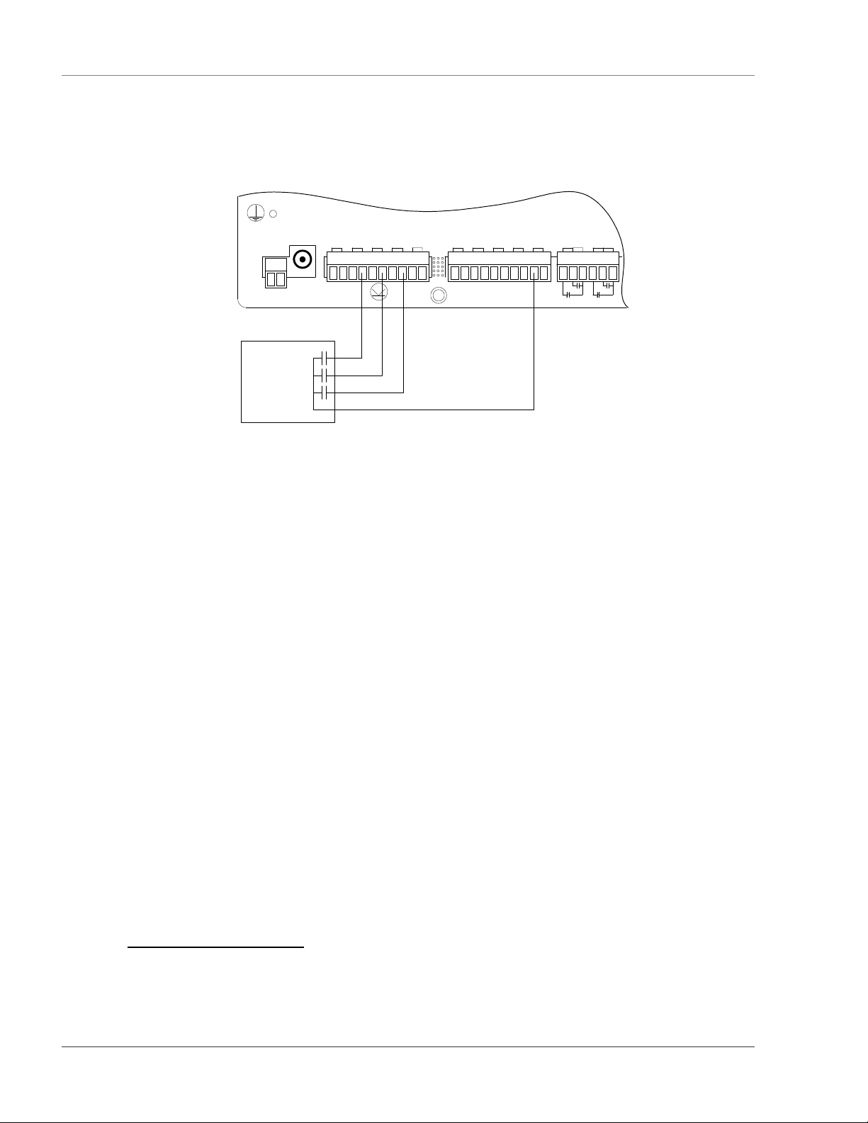
Some equipment may have several dry contact outputs with a Common Ground. Connect this equipment as
shown in Figure 2-4 below.
www.rletech.com 970 484-6510 7
Page 22
Getting Started User Guide: Falcon FMS
P1
EXTERNAL
TB1
VDC
+ -
VDC
24VDC
+ +
TB2 Input 1-4
Ch1
Ch2
+ -
+ -
Ch3
+ -
Ch4
+ -
TB3 Input 5-8
Ch5
+ -
Ch6
+ -
Ch7
+ -
Ch8
+ -
EXTERNAL
GND
- -
RELAY 1
NC NO C
TB4
RELAY 2
NC NO C
UPS
ON Bypass
ON Battery
Low Battery
Figure 2-4: Dry Contact Iputs with Common Ground
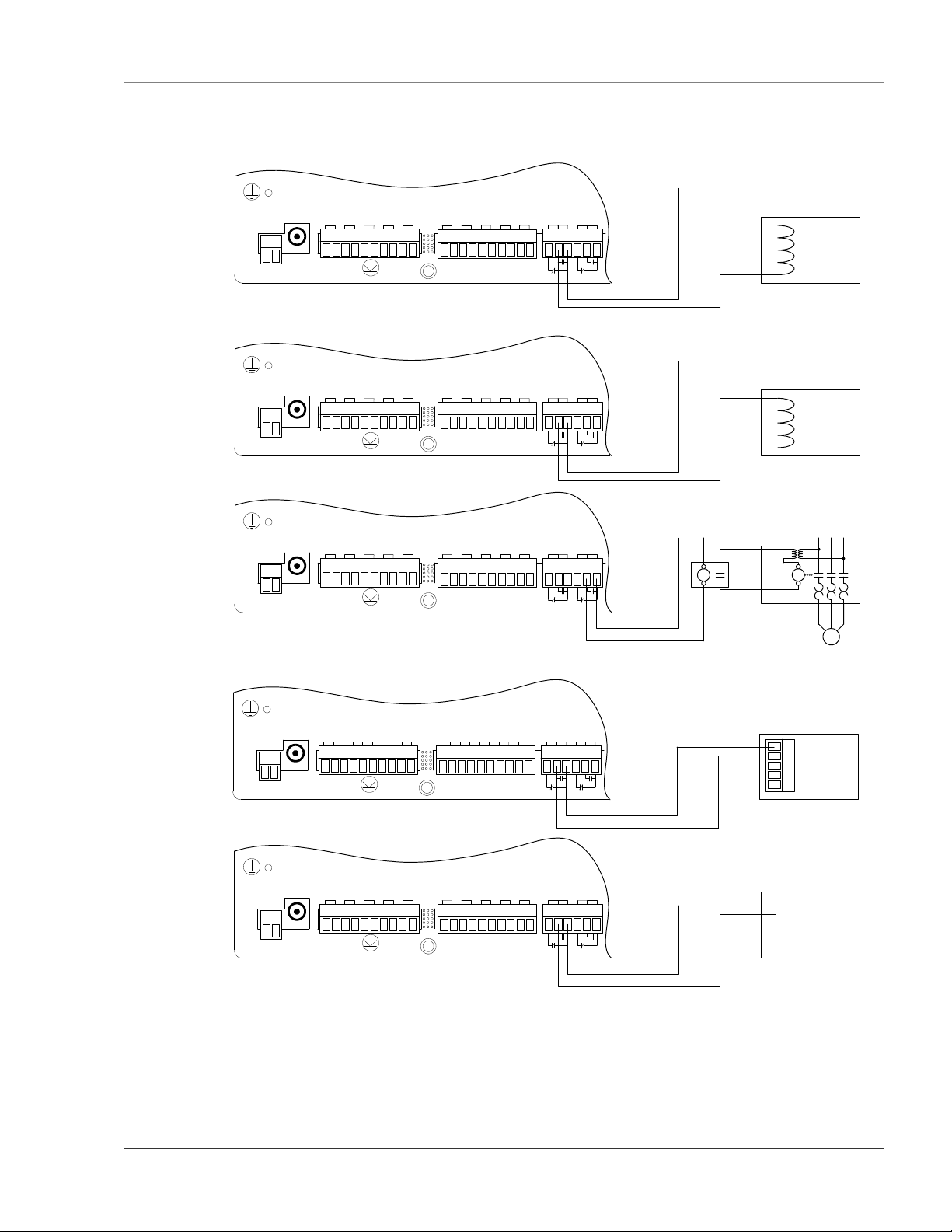
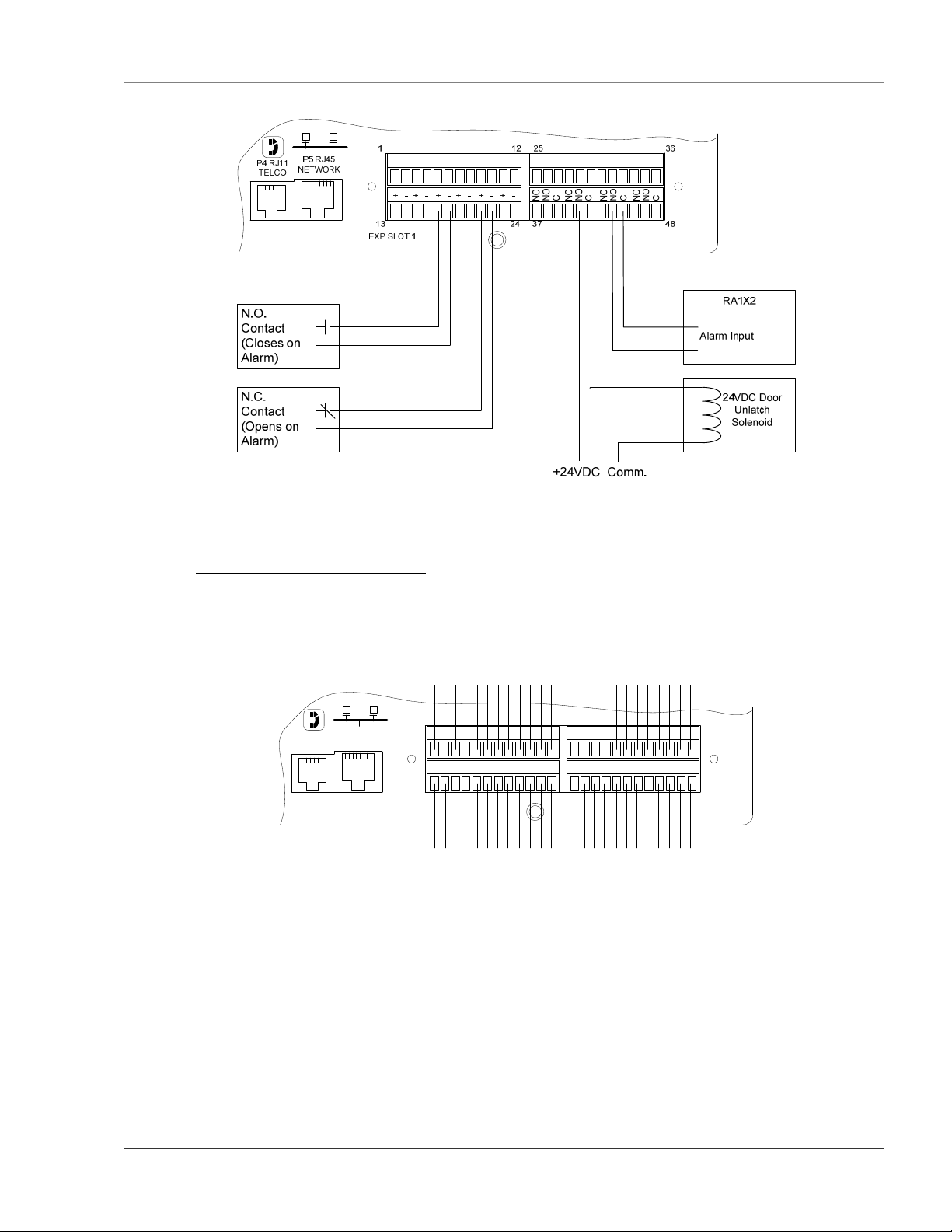
2-2.3 Relay 1 and 2 Connections
Relay outputs may be used to unlatch doors, signal annunciators, signal IP cameras, and to turn on auxiliary
equipment such as exhaust fans. Relay outputs are Form C (SPDT). Refer to specifications in APPENDIX
D: FMS Accessories Wiring on page 109, for relay contact ratings. Relays may be configured, through the
8 970 484-6510 www.rletech.com
Page 23
User Guide: Falcon FMS Getting Started
FMS for Normally Open (NO—unsupervised or normally de-energized), or Normally Closed (NC—
supervised or normally energized) operation; see Figure 2-5: Relay Output Wiring Examples for examples.
+24VDC Comm.
TB1
VDC
+ -
TB1
VDC
+ -
P1
VDC
P1
VDC
EXTERNA
L
24VDC
+ +
EXTERNA
L
24VDC
+ +
TB2 Input 1-
4
Ch1
Ch2
+ -
+ -
TB2 Input 1-
4
Ch1
Ch2
+ -
+ -
Ch3
Ch4
+ -
+ -
Ch3
Ch4
+ -
+ -
Ch5
+ -
Ch5
+ -
TB3 Input 5-
8
Ch6
Ch7
+ -
+ -
TB3 Input 5-
8
Ch6
Ch7
+ -
+ -
Ch8
+ -
Ch8
+ -
EXTERNA
L
GND
- -
EXTERNA
L
GND
- -
RELAY
NC NO
1
C
RELAY
NC NO
1
C
TB4
TB4
RELAY
NC NO
2
C
RELAY
NC NO
2
C
120VAC
L N
24Vdc Door Unlatch
Solenoid
120VAC Door
Unlatch Solenoid
VDC
P1
VDC
VDC
L
4
Ch1
Ch2
Ch3
24VDC
+ -
+ +
TB2 Input 1-
EXTERNA
L
Ch1
24VDC
+ -
+ +
TB2 Input 1-
EXTERNA
P1
L
Ch1
24VDC
+ -
+ +
Ch4
+ -
+ -
+ -
4
Ch2
Ch3
Ch4
+ -
+ -
+ -
4
Ch2
Ch3
Ch4
+ -
+ -
+ -
TB1
VDC
+ -
NOTES:
1. Interposing Relay may not be required if Motor Starter control power is
120VAC and requires less than 0.5A.
2. Control Power for interposing relay can be connected to the Motor
Starter if the Motor Starter control power is 120VAC
TB1
VDC
+ -
TB1
VDC
+ -
TB2 Input 1-
EXTERNA
P1
Ch5
+ -
Ch5
+ -
Ch5
+ -
TB3 Input 5-
8
Ch6
Ch7
+ -
+ -
TB3 Input 5-
8
Ch6
Ch7
+ -
+ -
TB3 Input 5-
8
Ch6
Ch7
+ -
+ -
Ch8
+ -
Ch8
+ -
Ch8
+ -
EXTERNA
L
GND
- -
EXTERNA
L
GND
- -
EXTERNA
L
GND
- -
RELAY
NC NO
RELAY
NC NO
1
C
RELAY
NC NO
1
C
1
C
TB4
TB4
TB4
RELAY
NC NO
RELAY
NC NO
C
RELAY
NC NO
Control Power for
Interposing Relay
2
C
Interposing
Relay
2
2
C
Motor
Starter
Blower
Motor
Web Camera
External
RA1X2
RASP1
Provides
Audible
Alarm
Sensor
Input
Figure 2-5: Relay Output Wiring Examples
www.rletech.com 970 484-6510 9
Page 24
Getting Started User Guide: Falcon FMS
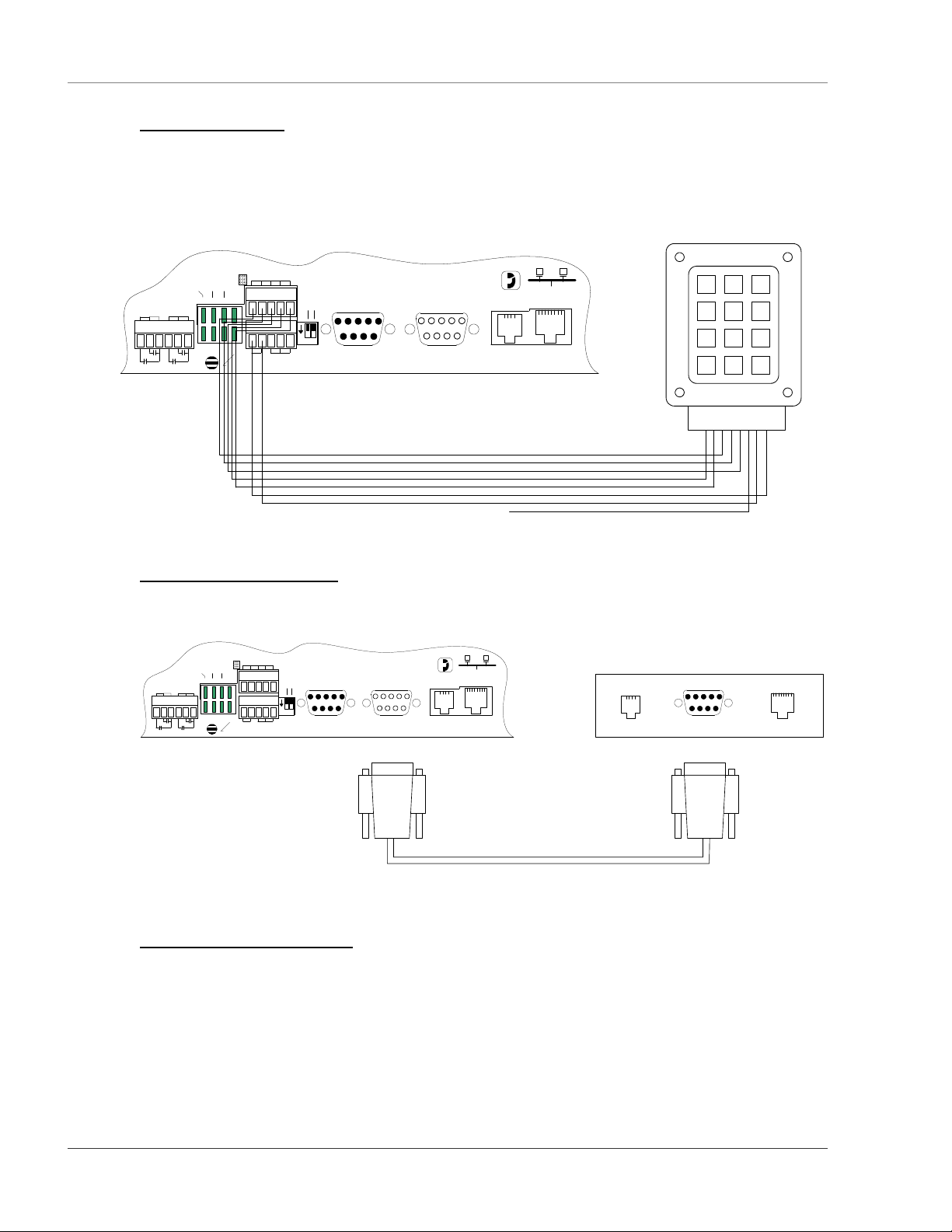
2-2.4 Keypad Connection
The FMS has a 3 x 4 keypad interface. Entering a user code, configured through software, can activate a
relay output which unlatches a door and allows an individual to enter the secure area. Entering the correct
user code can also trigger a relay output to signal an IP camera to snap a picture and email it to a predefined
recipient. Connect the keypad as shown in Figure 2-6. For more information on configuring the keypad
function, see section 3-17 Keypad/DTMF Access Users on page 45.
RLE - KPO Keypad
TB5 KEYPAD
COM1 SELECT
+ - GND
RS485 COM1
IOIOI
485 TERM
SEL M/S
1 2
ON
SW1
RELAY 1
NC NO C
TB4
RELAY 2
NC NO C
RELAY COM1 COM2
K1 TX TX 232
K2 RX RX 485
2-2.5 EIA232 COM2 Connection
The EIA232 port can be connected to a PC for IP configuration, firmware downloads, and troubleshooting.
It is typically a temporary connection. Connect the straight through, 9-pin, cable as shown in Figure 2-7.
RELAY 1
NC NO C
TB4
RELAY 2
NC NO C
RELAY COM1 COM2
K1 TX TX 232
K2 RX RX 485
COM1 SELECT
TB5 KEYPAD
+ - GND
RS485 COM1
IOIOI
P2 RS232
485 TERM
SEL M/S
COM1
1 2
ON
SW1
IOIOI
IOIOI
P2 RS232
COM1
Falcon TB5-1
Falcon TB5-2
Falcon TB5-3
Falcon TB5-4
Falcon TB5-5
Falcon TB5-6
Falcon TB5-7
IOIOI
P3 RS232
COM2
Column 1
Column 2
Column 3
Row 1
Row 2
Row 3
Row 4
No Connection
P4 RJ11
TELCO
Keypad Pin 3 - Orange
Keypad Pin 4 - Green
Keypad Pin 5 - Grey
Keypad Pin 1 - Red
Keypad Pin 2 - White
Keypad Pin 8 - Yel low
Keypad Pin 7 - Bl ue
Keypad Pin 6 - Bl ack
P5 RJ45
NETWORK
Figure 2-6: Keypad Wiring
IOIOI
P3 RS232
COM2
P4 RJ11
TELCO
P5 RJ45
NETWORK
(Female)(Male)
(Male) (Female)
Back of PC or Laptop
COM PORTModem LAN 10baseT
(Male)
1 2 3
4 5 6
7 8 9
* 0 #
Pin 1
Pin 2
Pin 3
Pin 4
Pin 5
Pin 6
Pin 7
Pin 8
RS232 Cable (Straight Thru - Shipped with Falcon)
Figure 2-7: EIA232 COM2 Connection
2-2.6 RJ11 Phone Line Connection
The FMS contains an internal modem for dial in and dial out capabilities. The modem can be used for:
Email notification through an Internet Service Provider (ISP).
Remote connection to accomplish a variety of tasks, including: viewing alarms, changing IP
configurations, and acknowledging alarms.
Remote alarm acknowledgment and access through DTMF. This allows a user to dial the FMS
from a touch tone telephone—standard phone or cell phone—and enter an acknowledgment code or
access code.
10 970 484-6510 www.rletech.com
Page 25
User Guide: Falcon FMS Getting Started
Pager notification to text, numeric pager or alpha-numeric pager (TAP changer). Text and numeric
pagers do not use a TAP changer.
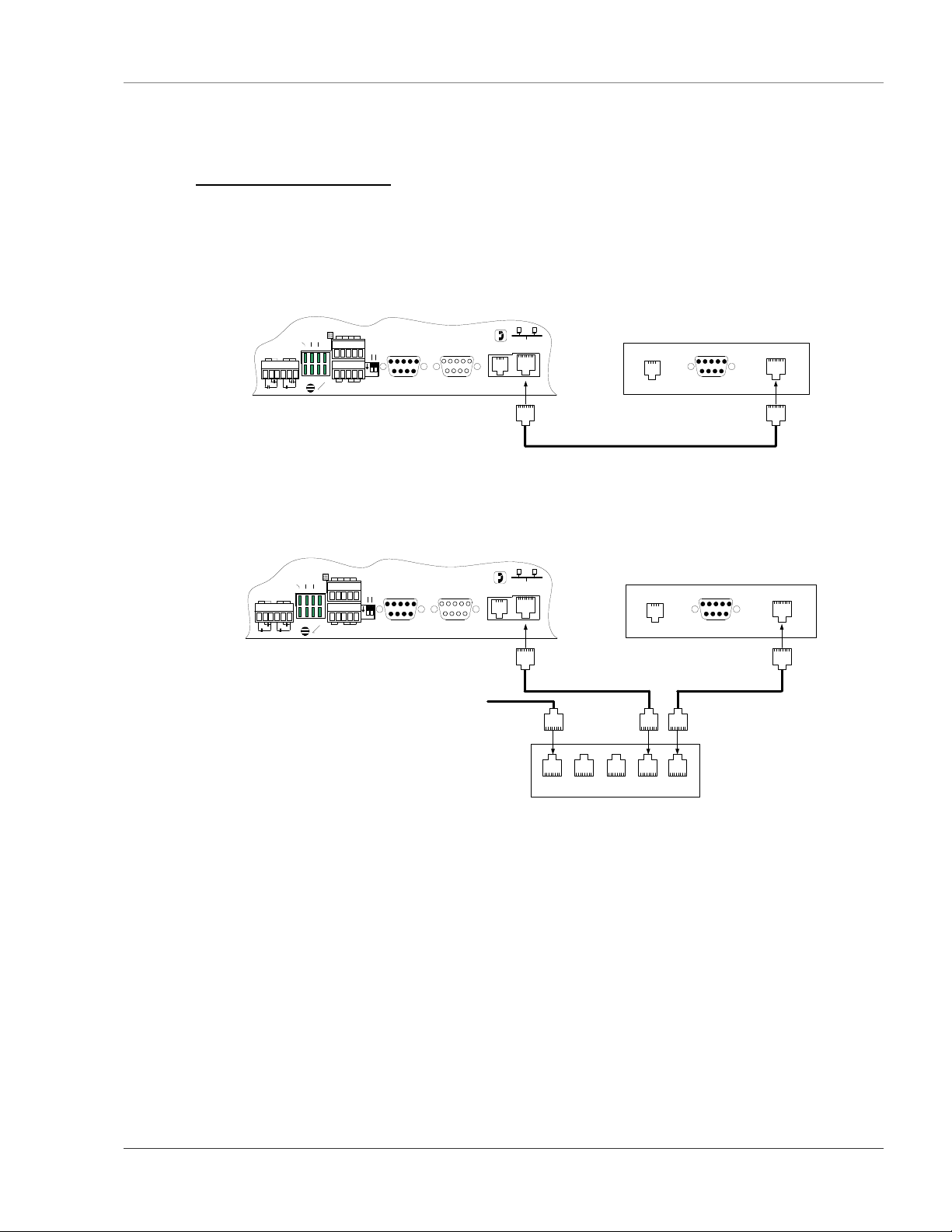
2-2.7 RJ45 Ethernet Connection
The FMS has an internal 10BASE–T Ethernet port used to configure and monitor the FMS. The Ethernet
port supports Web browser access, email (SMTP), BACnet slave, Modbus slave, SNMP and when the
EXP-MBCS option is installed, BACnet master and Modus master. Figures 2-8 and 2-9 show the physical
connections. Figure 2-8 shows a direct connection between the FMS and a PC using the crossover cable
supplied with the FMS. Figure 2-9 shows a typical FMS connection on a subnet using a hub or switch and
straight through CAT5 cables.
RELAY 1
NC NO C
TB4
RELAY COM1 COM2
RELAY 2
NC NO C
K1 TX TX 232
K2 RX RX 485
COM1 SELECT
TB5 KEYPAD
+ - GND
RS485 COM1
IOIOI
P2 RS232
485 TERM
SEL M/S
1 2
ON
SW1
IOIOI
IOIOI
P3 RS232
COM1
COM2
(Female)(Male) (Male)
P4 RJ11
TELCO
P5 RJ45
NETWORK
Back of PC or Laptop
COM PORTModem LAN 10baseT
Crossover CAT5 Cable (ships with Falcon)
Figure 2-8: FMS Ethernet Connection to a PC using a Crossover Cable
RELAY 1
NC NO C
TB4
RELAY 2
NC NO C
RELAY COM1 COM2
K1 TX TX 232
K2 RX RX 485
COM1 SELECT
TB5 KEYPAD
+ - GND
RS485 COM1
IOIOI
P2 RS232
485 TERM
SEL M/S
COM1
1 2
ON
SW1
IOIOI
To Other Devices on the Subnet
IOIOI
P3 RS232
COM2
(Female)(Male) (Male)
P4 RJ11
TELCO
P5 RJ45
NETWORK
HUB or SWITCH - 10/100BaseT
Back of PC or Laptop
COM PORTModem LAN 10baseT
Figure 2-9: FMS Ethernet Connection to a PC on a Sub-Net
www.rletech.com 970 484-6510 11
Page 26
Getting Started User Guide: Falcon FMS
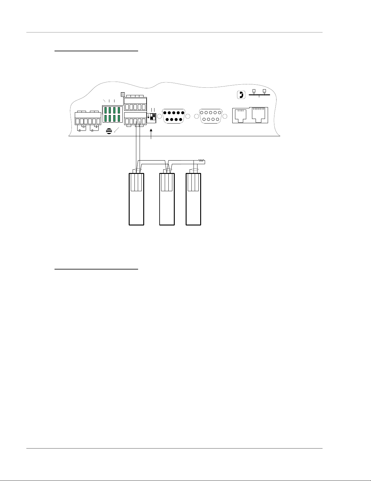
2-2.8 Modbus EIA485 Connections
The FMS can function as a Modbus Master or Slave over an EIA485, 2-wire hardware connection. The
EXP-MBCS option is required to allow the FMS to function as a Modbus Master. This option must be set
at the factory for an FMS to have Modbus capabilities.
TB5 KEYPAD
COM1 SELECT
+ - GND
RS485 COM1
Shield
Modbus Device
RELAY 1
NC NO C
TB4
RELAY 2
NC NO C
RELAY COM2 COM1
K1 TX TX 232
K2 RX RX 485
Figure 2-10: FMS EIA485 Connection
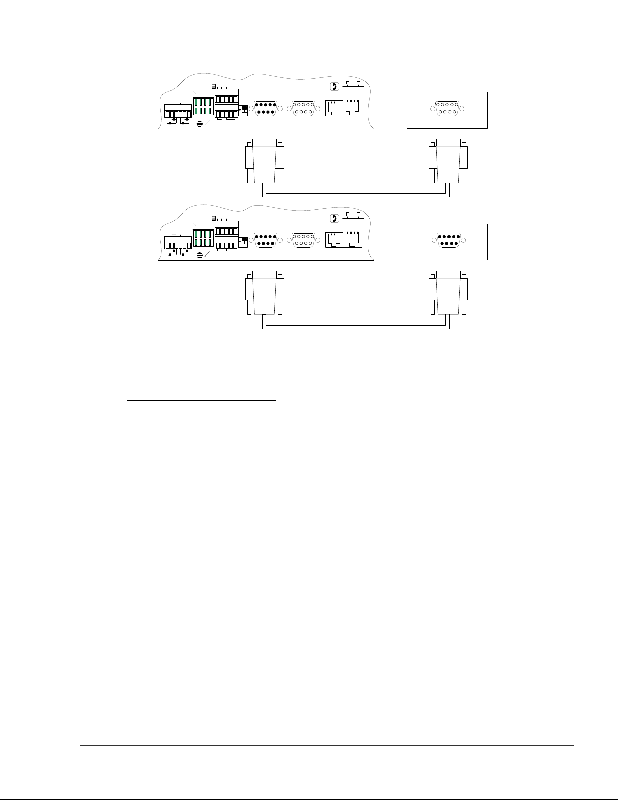
2-2.9 Modbus EIA232 Connections
The FMS can function as a Modbus Master or Slave over an EIA232 hardware connection. The EXPMBCS option is required to allow the FMS to function as a Modbus Master. The EIA232 port is configured
as a DTE device.
485 TERM
SEL M/S
1 2
ON
SW1
IOIOI
Switch #1 = On,
Inserts 100 Ohm
Termination Resistor
TX-/RX-
TX+/RX+
<Name/Slave
Address>
IOIOI
P2 RS232
COM1
Shield
TX-/RX-
TX+/RX+
<Name/Slave
Address>
Modbus Device
100 Ohm
Termination
Resistor
Shield
TX-/RX-
TX+/RX+
<Name/Slave
Modbus Device
IOIOI
P3 RS232
COM2
(Female)(Male)
Address>
P4 RJ11
TELCO
P5 RJ45
NETWORK
12 970 484-6510 www.rletech.com
Page 27
User Guide: Falcon FMS Getting Started
RELAY 1
NC NO C
RELAY 1
NC NO C
TB4
TB4
RELAY 2
NC NO C
RELAY 2
NC NO C
RELAY COM2 COM1
K1 TX TX 232
K2 RX RX 485
RELAY COM2 COM1
K1 TX TX 232
K2 RX RX 485
COM1 SELECT
COM1 SELECT
TB5 KEYPAD
+ - GND
RS485 COM1
TB5 KEYPAD
+ - GND
RS485 COM1
IOIOI
P2 RS232
485 TERM
SEL M/S
1 2
ON
SW1
IOIOI
(Female)
IOIOI
P2 RS232
485 TERM
SEL M/S
1 2
ON
SW1
IOIOI
(Female)
IOIOI
P3 RS232
COM1
COM1
COM2
(Female)(Male)
IOIOI
P3 RS232
COM2
(Female)(Male)
P5 RJ45
P4 RJ11
NETWORK
TELCO
RS232 Cable (Straight Thru)
P5 RJ45
P4 RJ11
NETWORK
TELCO
RS232 Cable (Null Modem)
MODBUS DEVICE (RTU - RS232/DCE)
COM PORT
MODBUS DEVICE (RTU - RS232/DTE)
COM PORT
Figure 2-11: FMS EIA232 Connection to a DCE or DTE Device
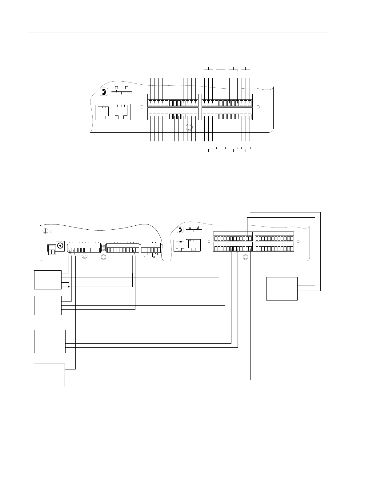
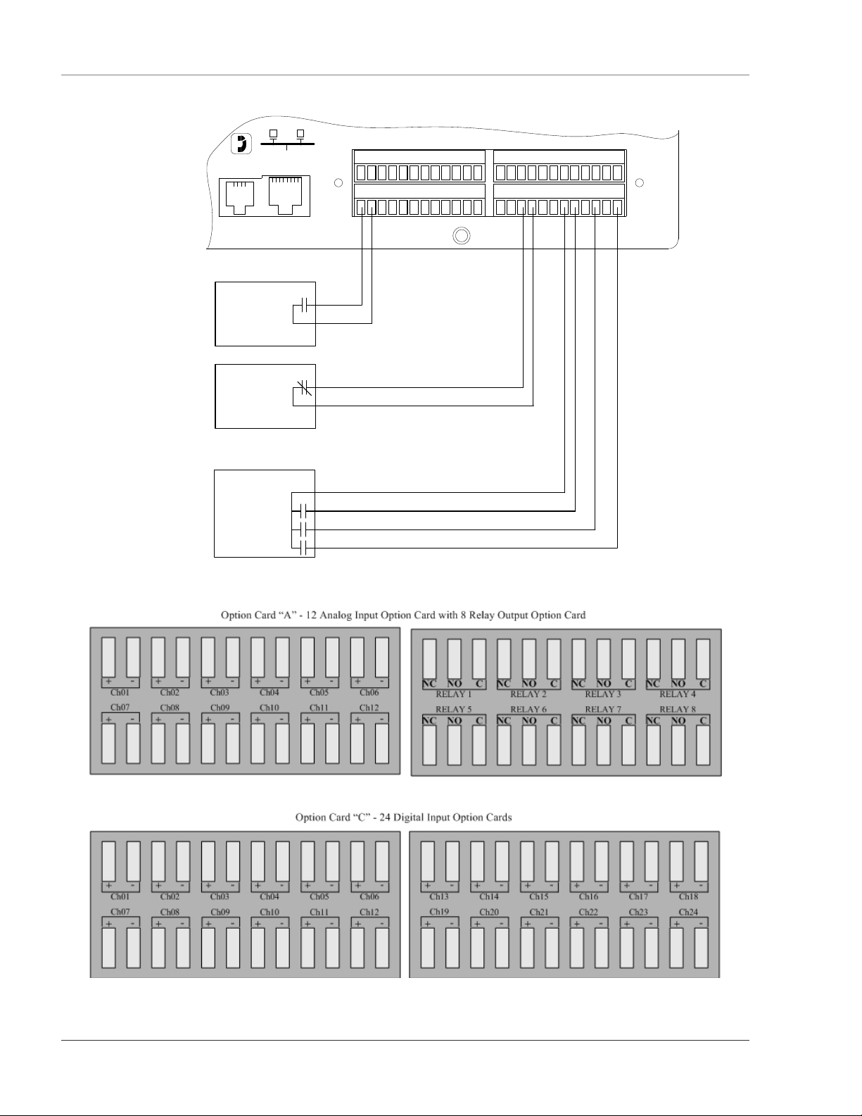
2-2.10 Expansion Card A Connections
A sticker identifying the Expansion Cards as A or C is located on each Expansion Card. The following
wiring diagrams show the Expansion Card in Slot 1. However, the Expansion Card may be in Slot 2, 3 or 4
based on the FMS configuration. The I/O for each card type appears on the back of the FMS for reference
during field wiring; see Figure 2-13 pg. 14 and Figure 2-16, pg. 16 for typical wiring. For information on
Expansion Card B, see APPENDIX H: Expansion Card B, pg. 127.
Expansion Card A has 12 non-isolated analog input channels and 8 relay output channels. The analog input
channels can be wired for 4-20mA, 0-5VDC, 0-10VDC, NO (normally open) dry contact or NC (normally
closed) dry contact. The circuit board has internal jumpers to select an mA input or a voltage input. The
factory default is set as a 4-20mA input. See APPENDIX A: FMS Expansion Cards, pg. 100, for jumper
location and settings.
www.rletech.com 970 484-6510 13
Page 28
Getting Started User Guide: Falcon FMS
Relay 1
Relay 2
Relay 3
Relay 4
Ch 1
Ch 2
Ch 3
Ch 4
Ch 5
+ -
+ -
+ -
+ -
+ -
+ -
Ch 6
NCNOC
NCNOC
NCNOC
NCNOC
TB1
VDC
P4 RJ11
TELCO
P5 RJ45
NETWORK
1
13
EXP SLOT 1
+ -
Ch 7
+ -
Ch 8
+ -
Ch 9
+ -
12 25
C
+ -
+ -
Ch 10
Ch 11
C
NC
NC
NO
NC
NO
NO
Ch 12
Relay 6
Relay 5
Relay 7
36
4824 37
C
C
NC
NO
Relay 8
Figure 2-12: Expansion Card A I/O Terminals
P5 RJ45
P1
EXTERNAL
24VDC
+ +
TB2 Input 1-4
Ch1
Ch2
+ -
+ -
Ch3
+ -
VDC
+ -
TB3 Input 5-8
Ch5
Ch4
+ -
+ -
EXTERNAL
Ch6
Ch7
Ch8
+ -
+ -
+ -
TB4
GND
RELAY 1
NC NO C
RELAY 2
NC NO C
- -
P4 RJ11
TELCO
NETWORK
1
+ - + - + - + -
13
EXP SLOT 1
+ - + -
12 25
+ -
36
4824 37
PWR
4 Wire
Sensor
COM
PWR
3 Wire
Sensor
Humidity Sensor
Voltage
Sensor
Out
COM
Temperature/
T-OUT
RH-OUT
PWR
COM
TH140/TH140D
Loop
Powered
Sensor
PWR
T-OUT
RH-OUT
+
-
T120/T120D
Loop
Powered
Sensor
PWR
T-OUT
Figure 2-13: Analog Input Wiring for Expansion Card A
14 970 484-6510 www.rletech.com
Page 29
User Guide: Falcon FMS Getting Started
Figure 2-14: Dry Contact Inputs with Individual Ground and Relay Outputs, Card A
2-2.11 Expansion Card C Connections
Expansion Card C has 24 dry contact input channels.
P5 RJ45
P4 RJ11
NETWORK
TELCO
13
EXP SLOT 1
Figure 2-15: Expansion Card C I/O Terminals
Ch 1
Ch 2
Ch 3
Ch 4
Ch 5
Ch 6
Ch 13
Ch 14
Ch 15
Ch 16
Ch 17
+ -
+ -
+ -
+ -
+ -
+ -
+ -
+ -
+ -
+ -
1
+ -
+ -
+ -
+ -
Ch 7
Ch 8
Ch 9
12 25
+ -
+ -
+ -
+ -
+ -
+ -
Ch 10
Ch 11
Ch 12
Ch 19
Ch 20
Ch 21
Ch 18
+ -
+ -
36
4824 37
+ -
+ -
Ch 22
Ch 23
Ch 24
www.rletech.com 970 484-6510 15
Page 30
Getting Started User Guide: Falcon FMS
P4 RJ11
TELCO
P5 RJ45
NETWORK
N.O.
Contact
(Closes on
Alarm)
N.C.
Contact
(Opens on
Alarm)
UPS
ON Bypass
ON Battery
Low Battery
1
+ - + - + - + - + - + - + - + - + - + - + - + -
13
EXP SLOT 1
12 25
36
4824 37
Figure 2-16: Typical Wiring for Expansion Card C
Figure 2-17: Falcon FMS Expansion Cards A & C
16 970 484-6510 www.rletech.com
Page 31

User Guide: Falcon FMS Getting Started
2-3 COMMUNICATION
The FMS will not communicate over a user’s network the first time it is connected to the network. The
manufacturer programs the FMS with a default IP address: 10.0.0.189, Subnet Mask: 255.255.255.0. This
default address must be changed to an IP address that corresponds with the user’s network before the FMS
can communicate over the network.
2-4 SET THE FMS IP ADDRESS
There are three ways to set the FMS IP address:
via the ARP and PING commands
via the Web browser
via the EIA232 interface
2-4.1 Set the IP Address Using the ARP and PING Commands
To set the IP address of a manufacturer programmed FMS, you can use the ARP (Address Resolution
Protocol) command together with the PING (ICMP echo request) command. However, before using these
commands, you must know the Ethernet address of the FMS.
2-4.1.1 Obtain the Ethernet Address (MAC Address)
Each network device must have its own unique identification. This identification sets it apart from all other
manufacturers and ensures that no two network devices have the same address. Each manufacturer must
use a six digit numbering convention (six sets of two digits with both letters and numbers). The first three
digits determine the actual manufacturer, and the remaining three digits determine the unique network
serial number of each individual FMS.
A typical Ethernet address (also known as a MAC address - Media Access Control) from the FMS looks
like this: 00:90:5B:00:02:45
The Ethernet (MAC) address for the FMS is on the model number sticker located on the bottom of the
device.
2-4.1.2 Use the ARP Command
Once you know the Ethernet address of the FMS, use the ARP command with the correct parameters from
any computer located on the FMS subnet (e.g., Class C with a subnet of 255.255.255.0).
For example, enter the following from a command prompt:
arp -s 192.168.1.14 00-90-5b-00-02-45
This command tells the computer (from which the ARP command was entered) that the network device
with an IP address of 192.168.1.14 uses the Ethernet (MAC) address of 00-90-5b-00-02-45.
2-4.1.3 Use the PING Command
After the ARP command has been entered, the PING command must be entered from the same computer in
order to set up the IP address of the FMS. The PING command will use the ARP entry added from Section
2-4.1.1, pg. 4, to send the IP address information directly to the FMS (which is just one of several methods
to initially configure the IP address on a new FMS).
To do this, enter the following from a command prompt:
PING ip_address
www.rletech.com 970 484-6510 17
Page 32

Getting Started User Guide: Falcon FMS
Where 'ip_address' is the IP address you entered using the ARP command. In the above example, the
following would be entered:
PING 192.168.1.14
This command changes the IP address of the FMS to: 192.168.1.14.
2-4.1.4 Troubleshooting the ARP/PING Commands
If problems are encountered, it may be for one of the following reasons:
The FMS already has a non-default TCP/IP address. Once the IP address of the FMS has been
changed from the default of 10.0.0.189, it is not possible to change it again with the ARP/PING
commands. This method of setting up the FMS IP address can only be used on an FMS that still
has its original default IP address, as shipped from the manufacturer.
The device is not on the same Class C subnet as the computer from which the ARP/PING commands
were sent. The FMS default router and Subnet Mask must be changed via a Web browser pointed at
the FMS default IP address (i.e., http://10.0.0.189) or via a direct EIA232 terminal connection to the
FMS—both of which are alternate methods for setting up the FMS IP address.
2-4.2 Set the IP Address Using a Web Browser
1. Plug the blue and yellow crossover network cable that shipped with the FMS unit into the laptop or
workstation that will be used to configure the FMS. This cable is not intended to be connected to a
network hub.
2. Write down the computer’s IP address and Subnet Mask. Then change the IP address and Subnet Mask
of the computer from its existing address to one that will allow it to communicate with the FMS, such
as 10.0.0.188. It may be beneficial to set the IP address to one that is one number different from the
FMS IP address. Consult the computer’s manual or your IT Department before attempting this.
3. Connect the other end of the network cable to the Ethernet port on the back of the FMS. Access the
FMS through a Web browser by typing the IP address (10.0.0.189) into the location bar. Enter the
FMS user name and password when prompted.
NOTE:
The default user name is
password field empty.
4. Select the Configuration Menu link, then select the System link. Select the IP Configuration Menu
link and change the IP address, Subnet Mask, and default Gateway to one provided by the network
administrator. Press the Submit Changes button. The FMS will save the new IP address and reboot.
Once the FMS reboots, the system status LED stops flashing. You must now use the new IP address
and reset the computer to its original IP address and Subnet Mask.
5. Change the IP address of the computer back to its original IP address. If the computer was configured
as DHCP (the network domain controller assigns an IP address) return it to this state. This may require
assistance from your IT Department, or you may need to consult the computer’s manual.
“falcon” and there is no default password - leave the
6. The computer and the FMS are now both configured to communicate on the network. Both should be
accessible via the network. Connect the PC and the FMS to the network. From the PC Web browser,
type in the IP address of the FMS. Enter the user name and password as stated above to verify network
access to the FMS.
18 970 484-6510 www.rletech.com
Page 33

User Guide: Falcon FMS Getting Started
2-4.3 Set the FMS IP Address using an EIA232 Connection
To use the EIA232 interface:
1. Connect the EIA232 port (P3 – Com2) on the FMS to a terminal or PC running terminal emulation
software (HyperTerminal) with a 9-pin male-female straight through serial cable.
2. Set the appropriate communication port to 9600 baud, NO parity, 8 data bits, 1 stop bit,
(9600/N/8/1), and no software or hardware flow command.
3. Once the terminal emulation software starts, press Enter on the keyboard and the Main Menu should
appear. If the Main Menu does not appear, check the communication settings and make sure the unit is
powered on.
4. From the Main Menu type “SC” to select the System Configuration Menu.
5. From the main configuration menu type “2” to select the IP Configuration Menu.
6. From the IP Configuration Menu type “i” to change the IP address.
7. Enter the new IP address for the FMS. Separate each field with a decimal point – for example type
10.0.0.50 <enter>.
8. From the IP Configuration Menu type “m” to change the Subnet Mask.
9. Enter the new Subnet Mask for the FMS. Separate each field with a decimal.
10. From the IP Configuration Menu type “d” to change the default Gateway.
11. Enter the new default Gateway for the FMS. Separate each field with a decimal
12. Enter “x” to Exit and Save the new IP address. The FMS will erase a memory block and copy data to
Flash memory before rebooting.
13. The FMS IP address is now set and the FMS can be accessed through a Web browser using the new IP
address.
Refer to Chapter 6: EIA232 Interface, pg. 88, for more information on the EIA232 command set.
www.rletech.com 970 484-6510 19
Page 34

FMS Configuration User Guide: Falcon FMS
CHAPTER 3: FMS CONFIGURATION
3-1 FMS WEB INTERFACE OVERVIEW
The FMS Web interface provides a convenient way to configure basic settings from any Internet–enabled
computer. This chapter will walk users through the steps of configuring the FMS. It will cover the
following configuration options:
Inputs and Relays
System (Configuration for the FMS unit)
Network Statistics
ICMP PING
BACnet
User Administration (Web Access)
Web User Access Log
SNMP/SYSLOG
URL Links 1-5 and 6-10
Links
Nest/Egg
Modem
Alarm Management
Keypad/DTMF Access Users
Schedules
Battery
Clock
Email/DNS
Network Time Protocol (NTP)
Modbus/Com Port 1
Modbus/Slave Units
Flash Program
Product Registration
The FMS is shipped to the user with the IP address configured as
255.255.255.0. The user name is preconfigured as falcon. The unit is configured
of
without a password; when a password is requested, leave the space blank.
10.0.0.189 and a Subnet Mask
20 970 484-6510 www.rletech.com
Page 35

User Guide: Falcon FMS FMS Configuration
These pre–configurations can be customized through the System link on the Configuration Menu of the
Web interface. To change the FMS IP address, refer to section 2-4 Set FMS IP Address on page 17.
Netscape’s “Smart Browsing” feature complicates use of the FMS Web interface. To avoid complications,
turn off Smart Browsing by following the steps below:
1. In the menu bar at the top of the Netscape browser, click on Edit, then on Preferences.
2. Smart Browsing is a subcategory of the Navigator category. Access Smart Browsing and then click the
box in front of the “Enable ‘What’s Related’ ” option. Eliminate the check mark to disable this option.
3-2 MAIN MENU
To access the FMS Main Menu, type the IP address of the FMS into the location bar of the Web browser.
When the prompt appears, enter the default user name (falcon) and password (none—leave blank).
Figure 3-1: Initial Loggin for the FMS
Figure 3-2: Main Menu/Homepage of the FMS
www.rletech.com 970 484-6510 21
Page 36

FMS Configuration User Guide: Falcon FMS
The top of the page provides links to other pages for additional monitoring, control and configuration. To
Configure the FMS, select the Configuration option from the Main Menu of the FMS Homepage.
The Configuration page allows authorized users—with administrator or read-write privileges—to adjust the FMS
settings. Each link on the Configuration page displays more information about specific configuration settings.
Figure 3-3: Sample FMS Configuration Main Menu
3-3 INPUT AND RELAY
Figure 3-4: Sample FMS Input/Output Configuration Menu
Input and Relay allows users to program specific parameters for each FMS input and relay. Different FMS
models allow different numbers of inputs and relays. Only installed inputs and relays are displayed. Inputs
and relays are identified by their name and slot channel number (S.Ch). Clicking an input link will display
one of three input configuration pages: (1) Main Board Inputs 1-8, (2) Expansion Card “A” Inputs or (3)
Expansion Card “C” Inputs.
22 970 484-6510 www.rletech.com
Page 37

User Guide: Falcon FMS FMS Configuration
NOTE:
Users must push the Submit Changes button after they configure each input. Changes
not submitted before proceeding to the next input will be lost.
3-3.1 Main Board Input Configuration (Channels 1-8)
To configure the FMS main board inputs (channels 1-8), select the appropriate input number. A page
similar to figure 4-3 will appear.
Figure 3-5: Sample FMS Main Board Input Configuration
The number of the input that is being configured will appear in the upper left-hand corner, above the
Submit Changes button. Options on this configuration page are described below.
Current Readings: Displays the input current as sensed by the FMS and the calculated value based on the
offset and gain settings.
Example
www.rletech.com 970 484-6510 23
: The example illustrated above shows a current input of 14.771mA from the temperature
sensor. The FMS converts this value to 79.6°F. When the input Type is Digital NO,
Digital NC or Digital Status, the measured Raw Current Reading will typically be 0mA
or 24mA (depending on input). The Calculated Value will be a 0 or 1, with 1
representing an alarm condition.
Page 38

FMS Configuration User Guide: Falcon FMS
Select Input Type: Select based on the type of device connected to the input channel. Options include:
Not Configured:
Analog 4-20mA
Digital NO:
Select when there is nothing connected to the input.
: Select when the device connected to the input provides a 4-20mA output.
Select when the device connected to the input is a dry contact that is normally open
and closes on an alarm condition.
Digital NC
: Select when the device connected to the input is a dry contact that is normally closed
and open on an alarm condition.
Digital Status
: Select when the device connected to the input is a dry contact that only needs to
be monitored (status only), without alarms.
Select Input Type:
Physical:
This allows users to configure the channel to display a sensor that is wired to a FMS
Input, Channel 1 – 104.
Modbus Import:
This allows users to employ a channel to display Modus Register information on
the main page of the FMS. Virtual Slots can be added to the main page of the FMS to display
more Modbus Points; see Chapter 5: Communication, pg. 64.
Gain and Offset: Applies only to Analog 4-20mA input types. Inputs like temperature, humidity,
pressure, etc. connected to the FMS convert information to a 4-20mA signal. The FMS reads this raw 420mA signal and calculates a value based on the input and the predetermined gain and offset settings. The
idea is to determine the correct gain and offset values so that the FMS calculates and displays an accurate
reading. Without setting the correct gain and offset, the FMS will not convert the raw data correctly. As a
result, missed alarms or nuisance alarms could occur.
To set gain and offset values, click the Calculator link.
Figure 3-6: Gain and Offset Calculator
Enter the sensor’s range and press the Calculate button. Click the Return to Input 1 Configuration link
so that the gain and offset fields are automatically entered with the correct offset and gain settings. Gain
and offset values can also be determined by using the following formulas:
Gain for 4-20mA Transducer = (Sensor High Range Value– Sensor Low Range Value) / 4
Offset for 4-20mA Transducer = Sensor Low Range Value – Gain
Example
: Temperature sensor with a sensing range of 50-95°F – displayed in Fahrenheit
Gain = (95-50) / 4 = 11 (round to the nearest integer)
Offset = 50 – 11 = 39
Example
24 970 484-6510 www.rletech.com
: Temperature sensor with a sensing range of 50-95°F – displayed in Celsius
Page 39

User Guide: Falcon FMS FMS Configuration
Convert 50-95°F to 10-35°C and use the Celsius range for the calculations
Gain = (35-10) / 4 = 6 (round to the nearest integer)
Offset = 10 – 6 = 4
Example
: Humidity sensor with a range of 0 – 100% RH
Gain = (100-0) / 4 = 25
Offset = 0 – 25 = -25
Hysteresis (Deadband): The number that designates the amount an input reading must sway from its
preset alarm reading before it is classified as returned to normal. The Hysteresis provides a dead band
around the limit settings to prevent several alarms and return to normal alarms when the input is the same
as a limit setting.
The Hysteresis applies when the input type is Analog 4-20mA and is active for High Limit 1, High Limit 2,
Low Limit 1 and Low Limit 2.
Example
: A temperature sensor alarms when it reaches its High Limit 1 of 80°F. If Hysteresis is
set at four, the sensor must register less than 76°F before the FMS reports it as returned
to normal. In another example, a humidity sensor alarms when it reaches its Low Limit
2 of 30% RH. If the Hysteresis is set at five, the humidity must register more than 35%
before the FMS reports it as returned to normal.
Unit Of Measure (UOM): The 10 character field used to assign a unit of measure label to analog values,
such as °F, °C, % RH, Amps, Volts, PSI, etc. The unit of measure field is only required when the input type
is Analog 4-20mA. The unit of measure field is displayed on the Main Menu and in notification
(email/pager messages and SNMP Trap).
Alarm Delay: The amount of time the FMS waits to send an alert after an alarm condition is detected.
The FMS uses this same time delay to report a return to normal after the alarm condition clears. The alarm
delay is active for all input types except Not Configured.
Example
: An input is configured as a digital NO, labeled “CRAC UNIT ALARM” and has an
alarm delay of 10 seconds. When the CRAC unit alarms, it closes the contact to the FMS.
If the CRAC unit returns to normal and opens the contact to the FMS within the 10
second alarm delay, no alarm is generated in the FMS. If the CRAC unit remains in alarm
for 10 seconds or more, the FMS records the alarm and generates notification per the
input settings. If the CRAC unit returns to normal and alarms within the 10 second alarm
delay, the FMS does not record it as a return to normal. Once the CRAC unit returns to
normal for the 10 second alarm delay, the FMS records a return to normal and generators
notification per the FMS settings.
High Limit 2: Applies only when the input type is Analog 4-20mA. The FMS will record an alarm and
send notification when the FMS calculated value exceeds this limit. The High Limit 1 and High Limit 2 are
disabled when they are both set to 0. High Limit 2 will also activate any designated relays.
High Limit 1: Applies only when the input type is set for Analog 4-20mA. The FMS will record an alarm
and send notification when the FMS calculated value exceeds this limit. The High Limit 1 and High Limit 2
are disabled when they are both set to 0.
Low Limit 1: Applies only when the input type is Analog 4-20mA. The FMS will record an alarm and
send notification when the FMS calculated value falls below this limit. The Low Limit 1 and Low Limit 2
are disabled when they are both set to 0.
Low Limit 2: Applies only when the input type is Analog 4-20mA. The FMS will record an alarm and
send notification when the FMS calculated value falls below this limit. The Low Limit 1 and Low Limit 2
are disabled when they are both set to 0. Low Limit 2 will also activate any designated relays.
www.rletech.com 970 484-6510 25
Page 40

FMS Configuration User Guide: Falcon FMS
Alarm Dial Out (Internal Modem): The list of up to five pager numbers to which the FMS sends alarm
notification. The numbers correspond to phone numbers configured from the Configure Phone Number
links at the bottom of the Modem Configuration page. Separate each ID number with a comma. Enter zero
to disable. The FMS will dial the lowest number listed regardless of the order the numbers are listed; see
section 3-15.1Configure Phone Numbers on page 42 for more information.
Example
: If the Alarm dial out string is set to “3, 5, 1, 0, 0”, the FMS will dial Pager #1, Pager #3
and then Pager #5 when an alarm occurs. Pager notification will be sent when an input
alarms (high limit 2, high limit 1, low limit 1, low limit 2 is exceeded or the digital input
is in alarm). The “Dial Back on Returns” option on the Pager Configuration page
determines if the FMS will send a page when an input returns to normal; see section 3-
15.1Configure Phone Numbers, pg. 42.
Label: Used for input identification. Applies to all input types except “Not Configured”. For Analog input
types, this label is displayed on the FMS Main Menu and the Input Configuration Menu. When the input
alarms and/or returns to normal, the label is included in the Alarm History and notification messages. For
Digital NO and Digital NC inputs, the label is displayed on the FMS Main Menu, Input Configuration
Menu, Alarm History page and in notification messages only when the device is in alarm. For Digital
Status inputs, the label is displayed on the FMS Main Menu when the input is on. When the input turns on,
the label is also included in the Digital Status History.
Label (Digital input normal): Applies to input types Digital NO, Digital NC and Digital Status. This
field may be left blank. If it is left blank, the FMS displays the Label (from above). This label is displayed
on the main page when the input is normal, in the Alarm History when the input returns to normal and in
notification messages. For Digital Status inputs, the label is displayed on the Home page when the input is
off. When the input turns off, the label is also included in the Digital Status History.
Relay Configuration Link: Used to assign a High Level 2, Low Level 2, or Digital Alarm generated by
this input to the OR gate function block of the Relay Control Logic to a specific relay. To select the
relay(s), click on the link and check the relay box(es); see APPENDIX G: Relay Control Logic, pg. 125.
Email Recipient Notification: Designates up to eight email addresses for notification if the input goes
into alarm. Email addresses will be displayed once they are entered on the Email Configuration page.
Email notification will be sent to recipients whose names are checked when an input alarms and, if
designated, when an alarm returns to normal.
Alarm Disable by Schedule: Used to designate a period of time the input will be disabled or inactive. To
do this, select either the A or B schedules, which are defined in the Schedule Configuration menu. Within
the scheduled time, the point on the Main Menu will turn Blue to indicate that the input is currently being
disabled during its scheduled time. Once the scheduled time has past, the point will reactivate and return to
its normal color.
SNMP Trap: Used to enable or disable traps. The trap can also be disabled during one of the schedules.
High1/Low1 SNMP Traps: Used to disable the first level analog alarm until the alarm reaches the more
critical level 2.
Display Value: Used to show either Signed or Unsigned Values for the Displayed value calculated by the
FMS.
Example
: If you have Unsigned value selected, the FMS will not display a negative number on the
calculated reading.
NOTE:
Press the Submit Changes button when done to save all changes.
26 970 484-6510 www.rletech.com
Page 41

User Guide: Falcon FMS FMS Configuration
Individual Ground Type (digital in only): Defines the type of digital input as either Individual Ground
or Common Ground.
Individual Ground:
used if the monitored input is a single relay contact and two contacts—
common and NO or NC—are accessible.
Common Ground:
used if multiple relays are to be monitored that have the commons bussed or
tied together (only one common input connection) and only the NO or NC contacts are available
for each individual relay output. See the example below or refer to section 2-2 Falcon FMS Wiring
on page 4, for more information.
Example
: Configure input channels 1–2 for Individual Ground, and configure input
channels 4–6 for Common Ground.
TB1
VDC
+ -
N.O.
Contact
(Closes on
Alarm)
N.C.
Contact
(Opens on
Alarm)
P1
VDC
EXTERNAL
24VDC
+ +
TB2 Input 1-4
Ch1
Ch2
+ -
+ -
Ch3
Ch4
+ -
+ -
ON Bypass
ON Battery
Low Battery
UPS
TB3 Input 5-8
Ch5
+ -
EXTERNAL
Ch6
+ -
GND
Ch7
Ch8
+ -
+ -
TB4
RELAY 1
NC NO C
RELAY 2
NC NO C
- -
Figure 3-7: NO/NC Wiring Example
BACnet Instance: The BACnet object identifier. It is a numerical code used to identify the input. This
code must be unique within the BACnet device.
BACnet Units: A numerical code used to assign engineering units to this BACnet Instance. Refer to the
BACnet standard for further information.
3-3.2 Expansion Card “A” Input Configuration
To configure Expansion Card A, select the desired input or relay from the Input and Relay Configuration
page; see Figure 3-4, pg. 22. While units will vary depending on individual configurations, Expansion Card
A is typically numbered 1.1–1.12, 2.1–2.12, etc.
www.rletech.com 970 484-6510 27
Page 42

FMS Configuration User Guide: Falcon FMS
Figure 3-8: Expansion Card “A” Input Card
This page will be displayed when configuring an input on an Expansion Card “A”. It is identical to the
FMS Main Board Input Configuration page—see section 3-3.1, Main Board Input Configuration (Channels
1-8), pg. 23—with the following exceptions:
The Expansion Card “A” does not except common ground digital inputs. Therefore, the option for
Individual Ground Type (digital in only) is removed.
Analog 0-5VDC and Analog 0-10VDC options are added to the Input Type. The Expansion Card
“A” accepts analog inputs individually configurable through internal jumpers, as 4-20mA, 0 5VDC or 0-10VDC.
3-3.3 Expansion Card “C” Input Configuration
To configure Expansion Card C, select the desired input or relay from the Input and Relay Configuration
page; see Figure 3-4, pg. 22. While units will vary depending on individual configurations, Expansion Card
C is typically numbered 1.1–1.24, 2.1–2.24, etc.
Figure 3-9: Sample of Falcon FMS Configuration Main Menu
28 970 484-6510 www.rletech.com
Page 43

User Guide: Falcon FMS FMS Configuration
Figure 3-9 will be displayed when configuring inputs for Expansion Card “C”. It is similar to the FMS
Main Board Input Configuration page—see 3-3.1, Main Board Input Configuration (Channels 1-8), pg.
23—with the following exceptions:
The Input Type options do not include Analog 4-20mA since Expansion Card “C”
only accepts dry contact inputs.
The Gain, Offset, Hysteresis, Unit of Measure, High Limit 2, High Limit 1, Low Limit 1, and Low
Limit 2 are not available since Expansion Card “C” does not accept analog inputs.
The option for Individual Ground Type (digital in only) is removed. Expansion Card “C” accepts
Individual and Common Ground inputs; however, it does not require any software configuration.
3-3.3.1 Internal Temperature and Internal Humidity Configuration
Internal Temperature, Ch. 105, and Internal Humidity, Ch. 106, have the same options as a standard
channel configured as an analog input, but the gain value cannot be changed—it has a fixed value
internally. The Input Type for Internal Temperature is used to specify and display the input in Fahrenheit or
Celsius.
3-3.4 Relay Configuration
Figure 3-10: Sample FMS Relay Configuration
A screen similar to Figure 3-10 will be displayed when configuring relays. Options on this page are
described below:
Type: Each relay output can be configured for one of the following types—only one type per relay output:
NO (Non-Supervised): Configures the relay output to be normally de-energized. The relay
output will energize when activated by an input or by a schedule. The silkscreen labeling for the
relay outputs (NC, NO and C) refer to the state of the relay output when it is de-energized.
NC (Supervised): Configures the relay output to be normally energized. The relay output will
de-energize when activated by an input or by a schedule. The silkscreen labeling for the relay
outputs (NC, NO and C) refer to the state of the relay output when it is de-energized.
Force On: Energizes the relay out and allows a user with Read-Write or Administrator privileges
to turn on a relay output for control or testing purposes.
Force Off: Energizes the relay out and allows a user with Read-Write or Administrator privileges
to turn off a relay output for control or testing purposes.
Button Controlled: Adds a button to the Relay Control page allowing users with Read-Only
privileges to turn on or off a relay output for control purposes.
www.rletech.com 970 484-6510 29
Page 44

FMS Configuration User Guide: Falcon FMS
Keypad Controlled: Configures the relay output to be controlled by a keypad code or DTMF
code. The User Code Configuration link appears once the Keypad Controlled option is selected
and submitted; see Figure 3-11, pg. 30. The User Code Configuration link allows users to
link which access code will active the relay output.
Figure 3-11: Sample FMS Keypad/Relay Configuration
Label: Used for relay identification. This label appears on the Relay Status and Relay Control pages.
BACnet Instance: The BACnet object identifier. It is a numerical code used to identify the input. This
code must be unique within the BACnet device.
OR’d Alarm IDs: Displays the Alarm IDs of the inputs specified through the Relay Configuration link on
the Input Configuration Menu. The Alarm IDs displayed can be translated by using APPENDIX E: Alarm
ID Reference Tables, pg. 115. The Alarm IDs are also displayed on the Input Configuration page. The
Relay Control Logic diagram in APPENDIX G: Relay Control Logic, pg. 122, shows how the OR’d Alarm
IDs, AND’d Alarm IDs and the Combo Gate are internally connected.
AND’d Alarm IDs: Allows up to four Alarm IDs (High Limit, Low Limit or Digital Alarms) to be
specified for the AND Gate Function Block input of the Relay Control Logic. Alarm IDs can be obtained
from APPENDIX E: Alarm ID Reference Tables, pg. 115. The Alarm IDs are also displayed on the Input
Configuration page. The Combo Gate Function Block of the Relay Control Logic will either OR or AND
the OR’d Alarm and AND’d Alarm inputs together. The Relay Control Logic diagram in APPENDIX G:
Relay Control Logic, pg. 122, shows how the OR’d Alarm IDs, AND’d Alarm IDs and the Combo Gate are
internally connected.
On-Delay Time: Specifies the number of seconds the Relay Control Logic will be delayed before
activating the relay on alarm.
On-Duration Time: Specifies how long the relay will be active after a valid alarm combination is
recognized through the Relay Control Logic. A positive number entry in seconds will keep the relay in its
alarm state (activated) for the fixed period specified. A negative number entry in seconds will keep the
relay in its alarm state (activated) after the alarm condition has returned to normal for the fixed period
specified. A zero entry will configure the relay to be active until the alarm condition returns to normal.
30 970 484-6510 www.rletech.com
Page 45

User Guide: Falcon FMS FMS Configuration
Latch Mode (Non-Latching, Latching, Silenceable): Latching will cause the relay to latch, or remain in
its alarm state, when activated until it is reset by the user. If latching is selected, the on-duration time
function will be disabled.
Schedule: Designates which of the schedules (None, A or B) the relay will follow. The schedules are
specified in the Configuration Menu. If schedule A or B is selected, all other function blocks of the Relay
Control Logic for that relay will be disabled. This allows the relay output to be energized based on day-ofweek and time-of-day.
Logic Diagram: Refer to APPENDIX G: Relay Control Logic, pg. 125, for a complete relay logic
diagram.
3-4 SYSTEM
The System link allows users to configure basic FMS information. The FMS IP Address and Point-to-Point
Protocol may also be configured through this menu via the IP Configuration Menu link; see Chapter 8:
Point-to-Point Protocol, pg. 94, for more information.
Figure 3-12: Sample FMS System Configuration
System Name: Appears on the FMS Main Menu. The system name is also included as part of email and
pager notifications.
Web Title Bar Text: Appears at the top of every FMS webpage. This text will be visible when the FMS
webpage is minimized.
BACnet Device Name, BACnet Device ID and BACnet Description: Required for the FMS to allow a
Building Management System (BMS) to poll the FMS inputs using the BACnet protocol over LAN
connections. For further information regarding BACnet Device Name, BACnet Device ID and BACnet
Description, consult the BACnet Standard or your IT Department.
Web Refresh Rate: The rate at which the FMS webpages refresh themselves within the Web browser.
Only pages that display monitoring points are automatically refreshed (e.g., Main Menu, Relay Status,
View Points, and Modbus Slave pages). The default is 0 seconds (disabled), but is typically set for 15 to 20
seconds.
WARNING!!
DO NOT SET THE WEB REFRESH RATE LOWER THAN 5 SECONDS. This
could cause the screen to freeze or lock-up.
www.rletech.com 970 484-6510 31
Page 46

FMS Configuration User Guide: Falcon FMS
PDA Screen Width: Sets the width of the PDA webpages in the FMS to match the PDA device. The PDA
webpages can be accessed from the Web browser by entering /pda after the IP Address (e.g.,
10.0.0.189/pda). The FMS includes a PDA webpage view for the Main Menu, Identity and Alarm History
pages only.
Figure 3-13: Sample FMS PDA Width Configuration
Analog Average: Allows users to change the averaging method for analog inputs. Normally, the system
samples analog points once a second while tracking high and low values for each analog point. After sixty
seconds, the high and low values for these points and the average of these readings are recorded in the
Minute Log. To alter this method of averaging, change the value to one of the values listed in the drop
down menu. Zero or one maintains the method described above; a higher value changes the method of
averaging, and the manner by which high and low values are recorded. Refer to APPENDIX B: Analog
Averaging, pg. 106, for a more information.
HTML Main Page Points: Determines the number of monitoring points displayed on the Main Menu.
With the default of ‘0’, the Summary Alarm Box, Internal Temperature and Humidity Box and a link to
View All Points are displayed. Settings greater than ‘0’ will display the selected points with links to the
remaining points. It is typical to display all installed points. If the FMS is continuously monitored with a
Web browser, it may be desirable to set the HTML Main Page Points to ‘0’ and monitor the View all Points
page.
Digital Status Color: Determines the color of Digital Status points on the Main Menu when the input is
turned on. The options are green, gold and magenta. Typically, points are configured to be green and turn
red on alarm. However, inputs configured for Digital Status do not trigger notification. For these points,
this setting determines the color of the point when the input is on.
Main Webpage Frames: The default main page will use frames if ‘Yes’ is selected. This reduces the
amount of information that the webpage has to update on a page refresh and may minimize “Page Not
Found” errors when continuously monitoring the FMS from a Web browser.
32 970 484-6510 www.rletech.com
Page 47

User Guide: Falcon FMS FMS Configuration
NOTE:
Changes will not go into effect until the Submit Changes button is clicked.
3-4.1 IP Configuration Menu
Figure 3-14: Sample FMS IP Configuration Menu
The IP Configuration link found on the System Configuration page allows users to change a variety of
settings, including the FMS IP Address (used in point-to-point ‘PPP’), Default Router and Net Mask.
Contact a network administrator to obtain a valid IP Address for the network. Then, type the appropriate IP
Address, Net Mask (subnet), and Default Router into their respective fields.
HTTP Port: The FMS broadcasts its webpages on Port: 80 of the IP Address assigned. A zero in the field
block defaults the FMS to Port: 80. This can be changed to a specific port allowing increased security of
the webpage broadcast.
TFTP Server Enable (udp port: 69): This setting opens or closes Port 69 on the LAN connection to the
FMS. The TFTP port is used to upgrade firmware and save and load configurations. It can be disabled for
security reasons and only opened for short periods of time during firmware upgrades; see Chapter 9:
Upgrading Firmware, Loading & Saving Configuration Data, pg. 95, for more information.
TCP Max Segment Size: The FMS is defaulted to send webpages at a 1436 TCP segment size. A smaller
TCP segment size helps with a congested network. The 536 TCP segment size may be required if the FMS
is accessed through a VPN connection.
Disable Network Watchdog: This should be left at the “No” default. Do not select “Yes” unless
instructed by RLE.
PPP Server: Sets the IP Address of the FMS network connection when accessing the FMS via its internal
modem.This is required to allow a remote PC to view the FMS webpages over a dial-up connection; see
Chapter 8: Point-to-Point Protocol, pg. 94, for more information.
PPP Assignment: Sets the IP Address of the remote PC’s network connection when accessing the FMS
via its internal modem. This is required to allow a remote PC to view the FMS webpages over a dial- up
connection. The remote PC’s dial-up settings should be set to “Obtain an IP Address Automatically”.
www.rletech.com 970 484-6510 33
Page 48

FMS Configuration User Guide: Falcon FMS
NOTE:
Changes will not go into effect until the Submit Changes button is clicked.
3-5 NETWORK STATISTICS
Figure 3-15: Sample FMS Network Status Page
Network Statistics: Displays network and EIA485 statistics including: network packets received, packets
transmitted, and errors.
3-6 ICMP PING
Figure 3-16: Sample FMS ICMP Ping Page
ICMP Ping: Allows a user to ping an IP address from the FMS. The results of the ping will display below
in the “Last Ping Results” table.
34 970 484-6510 www.rletech.com
Page 49

User Guide: Falcon FMS FMS Configuration
3-7 BACNET
Figure 3-17: Sample FMS BACnet Configuration
BACnet Device Name, BACnet Device ID, and BACnet Description: Required for the FMS to allow
Building Management System (BMS) to poll the FMS inputs using the BACnet protocol over LAN
connections. For further information regarding BACnet Device Name, BACnet Device, and BACnet
Description, consult the BACnet Standard or your IT Department.
3-8 USER ADMINISTRATION (WEB ACCESS)
Figure 3-18: Sample FMS Web Access Configuration
The User Administration (Web Access) page allows the administrator to configure eight separate
accounts, usernames, passwords and privileges for Web access accounts.
Read-Only privileges allow the user to view the Main Menu, Keypad Access History, Alarm
History, Event History, Digital Data History, Identity, Relay Status, Relay Control and URL Links
webpages. The Configuration page cannot be viewed or changed by a Read-Only user. A ReadOnly user can acknowledge alarms by entering their acknowledge code at the bottom of the Alarm
History page. A Read-Only user cannot change any settings.
Read-Write privileges allow the user to have full access to all pages (viewing and changing)
except the User Administration (Web Access) page shown above.
www.rletech.com 970 484-6510 35
Page 50

FMS Configuration User Guide: Falcon FMS
Administrator privileges allow the user to have full access to all pages including the User
Administration (Web Access) page shown above.
3-9 WEB USER ACCESS LOG
Figure 3-19: Sample FMS Web User Access Log
The Web User Access Log records the most recent 100 Web interface users.
3-10 SNMP/SYSLOG
SNMP/Syslog Configuration allows users to configure SNMP and Syslog notification options; s
ee definitions below:
System Name: Appears on the FMS Main Menu and is included as part of email and pager notifications.
The System Name can also be viewed and changed in the System Configuration Menu.
System Contact: Lists the individual responsible for the FMS. The System Contact is only available
through SNMP Gets and is not included in email, pager, or SNMP Trap notifications.
Figure 3-20: Sample FMS SNMP Configuration
36 970 484-6510 www.rletech.com
Page 51

User Guide: Falcon FMS FMS Configuration
System Location: Lists the location of the FMS. It is used to help identify the FMS when viewing the
webpages. The System Location is not included in email, pager, or SNMP Trap notifications.
Persistent Traps: Enables the FMS to issue continuous SNMP Traps until an alarm acknowledgement is
received by the FMS or until the alarming point returns to normal. The parameter is a user defined time
interval that is set in minutes. Traps can be acknowledged from the Alarm Management page. The SNMP
Traps do not include any delivery verification. A Persistent Trap setting of 5 or 10 minutes will trigger the
FMS to send the Trap on a regular interval in case the previous Trap did not reach the Network
Management System (NMS). Typically, the NMS can be set to ignore duplicate Traps to prevent realarming at the NMS.
Analog Trap Varbinds: Used for communication to an NMS via SNMP Traps. The default will add the
Value, UOM (Unit of Measure), and the Label fields. The FMS can be configured to send only the label on
analog Traps, if preferred. This makes analog Traps the same format as digital Traps which may make
parsing the Traps easier for the NMS.
Trap Type: The default is set to send an “Alarm Entry Added” type Trap. The Trap Type can be set to a
Port Type Trap (falconPortTraps). Selecting “AlarmEntryAdded” enables the “AlarmEntryAdded” and
“AlarmEntryRemoved” Trap. An “AlarmEntryAdded” Trap will be sent anytime a new alarm is added to
the Alarm History log. The contents of the “AlarmEntryAdded” Trap contain the Alarm Label. The NMS
can receive the Trap, extract and display the Alarm Label. An “AlarmEntryRemoved” Trap will be sent
anytime a Return to Normal Alarm is added to the Alarm History log. The contents of the
“AlarmEntryRemoved” Trap contain the Alarm Label. Selecting “falconPortTraps” enables two Traps per
FMS input: a “FalconPortxxTrap” and a “FalconPortxxTrapClear”. For example, when input #1 goes into
alarm, the FMS sends a “FalconPort01Trap”. When input #1 returns to normal, the FMS sends a
“FalconPort01TrapClear”.
Selecting “AlarmEntryAdded” makes configuring the NMS easier, since the NMS only needs to be
configured for a couple Traps. Choosing “falconPortTraps” requires more configuration at the NMS, but
may make it easier to display, set severity, and parse the data in the NMS.
Trap Delivery: Determines if the SNMP Trap is sent out the LAN connection or dials out and sends the
SNMP Trap over the modem connection. If PPP is selected, the dial-up connection, or phone number 16,
needs to be configured. Phone numbers are configured through the Modem Configuration page by clicking
the 16 (PPP) link.
Communities: Identifies devices that receive SNMP Traps and/or Syslog messages from the FMS and
interacts with the FMS over the network. To add a device to the Communities list, select a community
number posted as “empty”. Enter the receiving device’s IP Address and a string that identifies the device.
An IP Address of 0.0.0.0 in this field allows any device to access the FMS through an MIB browser. Select
“Write” if the device will have Read/Write network access. This allows the FMS to be configured over the
network. Select “Traps” if the device will receive Traps from the FMS.
NOTE:
Refer to the “MIB Files Information” document located on the FMS webpage of our
website (www.rletech.com
Files.
) for more information on the SNMP Trap format and MIB
NOTE:
Changes will not go into effect until the Submit Changes button is clicked.
www.rletech.com 970 484-6510 37
Page 52

FMS Configuration User Guide: Falcon FMS
3-11 URL LINKS (1-5)
Figure 3-21: Sample FMS URL (1-5) Links Configuration
The Main Menu of the FMS Web interface displays a large image and links to other images. These images
can be graphics, logos or images from an IP camera. The URL Links (1-5) page allows users to specify
which images and URLs will be available from the first five links on the FMS Main Menu.
For Axis207 Web Cameras set the URL link to the following:
URL Link #x Image: http://xxx.xxx.xxx.xxx/jpg/image.jpg
URL Link #x Home: http://xxx.xxx.xxx.xxx
URL Link #x Label: Enter the Camera’s Label
For Panasonic KX-HCM110A Web Cameras set the URL link to the following:
URL Link #x Image: http://xxx.xxx.xxx.xxx/snapshotjpeg?resolution=320x240&quality=standard
URL Link #x Home:
http://xxx.xxx.xxx.xxx/ImageViewer?Mode=Motion&resolution=320x240&quality=standard
URL Link #x Label: Enter the Camera’s Label
3-12 URL LINKS (6-10)
Figure 3-22: Sample FMS URL (6-10) Links Configuration
38 970 484-6510 www.rletech.com
Page 53

User Guide: Falcon FMS FMS Configuration
The URL Links (6-10) page allows users to specify which images and URLs will be available from links
6-10 on the FMS Main Menu.
3-13 LINKS
Figure 3-23: Links Configuration Page
The Main Menu allows users to link to up to four other FMS units. The FMS Links page allows users to
designate the IP Addresses of these additional FMS units.
3-14 NEST/EGG
The Nest/Egg page allows users to configure the FMS Nest/Egg capabilities. More specifically, the FMS
contains a webpage, or “Nest”, that can monitor up to 32 other FMSs, or “Eggs”. The Nest will display the
name and a summary alarm from each Falcon Egg. The summary alarm status of each Egg will
automatically refresh based on the Web refresh rate determined for that individual FMS.
The Nest also provides a link for each Falcon Egg. When an alarm occurs, the summary alarm box turns
red and the operator can select the link to open the alarming FMS webpage to view the alarm.
Once configured, a “Falcon Nest” link appears at the bottom of the Main Menu. Clicking the “Falcon Nest”
link opens the Falcon Nest page where all configured Falcon Eggs are displayed; see Figure 3-24.
3-14.1 Falcon Nest Configuration
Figure 3-24: Sample FMS Nest Egg Page
www.rletech.com 970 484-6510 39
Page 54

FMS Configuration User Guide: Falcon FMS
Figure 3-25: Sample FMS Nest Configuration
The Falcon Nest link appears at the bottom of the Main Menu after the Nest/Egg has been configured. The
Falcon Nest page and all configured Falcon Eggs are displayed. The Nest Type option enables or disables
the Falcon nest page. Selecting “Frames” enables the nest page.
3-14.2 Egg Configuration
The Egg #1 Configuration link on the Falcon Nest page allows users to enter the IP Address and HTTP
port for each Falcon Egg. The HTTP port can be changed for added security. The HTTP port must be set
the same as the FMS HTTP configuration setting, located under the System Configuration Menu.
3-15 MODEM
The Modem link allows users to configure the FMS internal modem. This instructs the FMS when, how,
and whom to call when an alarm occurs; see definitions below for more information.
Figure 3-26: Sample FMS Egg Configuration
40 970 484-6510 www.rletech.com
Page 55

User Guide: Falcon FMS FMS Configuration
Figure 3-27: Sample FMS Modem Configuration
Initialization String: A maximum of 38 characters. &c1 and &d3 are mandatory. s0=1 sets the modem
to answer after one ring. s0=0 disables the auto answer and prevents dial-in access.
Dial Prefix: Should be a specific Hayes compatible command or dial modifier depending on pager
requirements. It is also limited to 38 characters. The default is set to atdt.
Pager Deliveries: Designates the number of times (0-255) the pager is called until the alarm is
acknowledged. Pagers are called in sequence.
Example:
If Pager Deliveries is set to 3 and pagers 1, 7, and 10 are programmed to be notified, the
FMS dials 1, 7, 10, 1, 7, 10, 1, 7, 10. As soon as the alarm is acknowledged, the FMS
quits dialing the pagers with that particular access code. Pagers with different access
codes are still dialed.
Pager Interval: Determines the number of minutes to wait between redials.
Pager No Ack Alarm: Defines which numbered pager contact (1-15) is called if an alarm is not
acknowledged. Enter 0 to disable this function.
Pager Log Full Alarm: Defines which numbered pager contact (1-15) is notified when the Alarm History
Log is full.
Pager Baud Rate: Allows the user to set the pager communications settings. Select 7 bit, even parity or 8
bit, no parity to match the settings of the pager service provider’s TAP service phone number.
Pager Unsuccessful Traps: Select yes to allow the FMS to send an SNMP Trap to the NMS in this event.
Pager Resend: Select yes for the FMS to send all unacknowledged alarms in the Alarm History Menu.
Select no to send only the last unacknowledged alarm. If no is selected, the FMS will auto-acknowledge all
alarms associated with that particular pager once a successful page has occurred.
Modem Password: Defines a remote access password, seven characters maximum. The password is used
when remotely logging into the FMS through a modem.
www.rletech.com 970 484-6510 41
Page 56

FMS Configuration User Guide: Falcon FMS
Redial Attempts: Determines the number of times (1–255) to call a number until the call is successful.
Enter 0 to disable this function.
Redial Interval: Establishes the number of minutes (1–255) to wait between redials. Enter 0 to disable
this function.
Comm Check Phone: Defines which numbered pager contact (1–15) is called to verify communications.
Enter 0 to disable this function.
Comm Check Time: Determines when (time in 24 hour format) a communications check will occur.
Force Alarm Acknowledge Code: Establishes a code that acknowledges all unacknowledged alarms.
This acts as a master code and can override all other alarm acknowledge codes.
Pager Message Strip Timestamp: Check to remove the alarm timestamp from the pager message. This
reduces the size of the pager message as the user can estimate when the alarm occurred based on when the
page was received.
NOTE:
Changes will not go into effect until the Submit Changes button is clicked.
3-15.1 Configure Phone Numbers
Figure 3-28: Sample FMS Phone Number Configuration
A screen similar to Figure 3-28 is accessed through the Config Phone Number link at the bottom of the
Modem Configuration page. This screen allows users to configure pager and cell phone numbers that are
used for alarm notification.
Select Phone Type: Determines which type of device the FMS calls. Select the Text option to dial a PC
receiving ASCII strings. Select Numeric Pager to dial a numeric pager. Choose the Alpha-numeric Pager
option to dial an alphanumeric pager.
Number: Enter the pager service number for numeric and alphanumeric pager entries. Each comma after
the pager number represents a two second delay. This delay allows time for the pager service to answer
before requesting the pager ID. Typically, it will only be necessary to use one comma between pager
numbers. However, based on set-up and pager services, users may need to experiment with the number of
commas that are used. In some cases, a 9 must be entered to access an outside line.
Pager ID: Mandatory for numeric and alphanumeric pagers.
42 970 484-6510 www.rletech.com
Page 57

User Guide: Falcon FMS FMS Configuration
Alphanumeric pager: The ID entered is sent to the paging service along with all queued alarm
messages. The ID is the unique PIN for a specific pager. The ID may be a maximum of 16
characters.
Numeric pager
: The ID entered may be configured to deliver different numeric messages. The
ID can contain 15 characters: any combination of the numerals 0 through 9 and a * or #. These are
the only characters that will be transmitted to the paging service. A $ can be added or inserted
anywhere in the message. This is converted into a 5 digit alarm code: YZZZZ.
Y - Binary Alarm Condition: 1=on, 0=return to normal (RTN)
ZZZZ - Alarm ID Number; see APPENDIX E: Alarm ID Reference Tables, pg. 115.
Example
: A 10011 message is an Input 1, High Limit 1 Alarm. A 04030 message means
that Digital Input #83 (in slot 4) has Returned to Normal.
NOTE:
When using the $, if multiple unacknowledged alarms are present in the Alarm History
Log, the alarm code will be 99999.
An effective numeric page depends largely on the parameters established by the paging service.
Users may need to experiment with different parameters in order to achieve desired results.
Acknowledgement Code: Any number, up to six digits, used to acknowledge receipt of an alarm and to
terminate any additional call outs for this phone number. This code will acknowledge only those alarms
sent to this phone number. The alarms can be acknowledged using this code by dialing the FMS with a
touch tone phone and entering this code followed by the # sign. It can also be acknowledged by selecting
the Acknowledge Alarms button on the bottom of the Alarm History page.
Multiple phone numbers can use the same acknowledge code. This allows one user to
acknowledge alarms sent to multiple pager numbers.
NOTE:
The Acknowledge Code should be different than the access codes. If this code is the
same as one of the access codes, the Falcon will acknowledge the alarms associated
with the acknowledge code, enter a successful entry in the Access Log, and activate the
relay outputs which are set for keypad activation.
Dial Back on Returns: Determines whether to call the number again once the alarm condition returns
to normal.
NOTE:
Changes will not go into effect until the Submit Changes button is clicked.
www.rletech.com 970 484-6510 43
Page 58

FMS Configuration User Guide: Falcon FMS
3-15.2 Configure Phone Number 16 (PPP)
Figure 3-29: Sample FMS Phone Number 16 (PPP) Configuration
This page is accessed through the 16 (PPP) link at the bottom of the Modem Configuration page. This
screen allows users to configure a dial-up networking account.
DUN Phone #: Specifies the phone number of the ISP to which you wish to connect.
DUN User Name: Enter your ISP account user name.
DUN Password: Enter the password associated with your ISP account.
3-16 ALARM MANAGEMENT
Figure 3-30: Sample FMS Alarm Settings Menu
The Alarm Management link allows users to perform the following tasks:
Acknowledge current FMS alarms.
Clear the FMS Alarm and Access History Logs.
Enter the appropriate code or user’s initials to acknowledge or clear alarm histories.
Enable or disable maintenance time.
Designate a maintenance window by selecting the Set Maintenance Time button, which will
disable alarm notifications for a designated period of time.
Enable or disable alarm logging during the maintenance window.
44 970 484-6510 www.rletech.com
Page 59

User Guide: Falcon FMS FMS Configuration
3-17 KEYPAD/DTMF ACCESS USERS
Figure 3-31: Sample FMS URL (6-10) Links Configuration
The Keypad/DTMF Access Users link allows configuration of a maximum of 20 access codes and user
names. The access code can be up to six digits long. The user name can be up to 20 characters long. Each
ID Code/User can be selected as a “Permanent” or “Temporary” type. Temporary users are only allowed
access during the time specified in the Temporary Time drop box. This time may be set by selecting the Set
Temporary Time button.
Once the time frame has expired, the temporary users will not be allowed access. However, their
information will remain in the Keypad/DTMF field until it is manually removed. While temporary users
will not be allowed access to a facility after their allotted time slot, no alarm notification will be transmitted
if they try to re-enter the facility through the keypad. Their information must be manually removed from
the system in order to activate the alarm notification.
Exit Request Inputs are used to prevent unnecessary alarms from being triggered. Exit Request Inputs
register when a motion sensor or keypad entry is entering or leaving a facility and then overrides the
normal alarm notification process (i.e., it prevents the system from registering normal entries or exits as
forced). The Exit Request input provides a dry contact that will signal a relay to unlock a door when the
contact closes from a button or motion sensor.
The Alarm Bypass Input is used in conjunction with the controlled access function of the FMS (digital
inputs 1-104). Typically a magnetic-based contact installed in a door detects the position of the door. This
contact sends a signal to the FMS to report door conditions such as “Forced” and “Held”. When enabled,
the alarm on the door is bypassed upon entry of this valid access code.
NOTE:
Press the Submit Changes button after configuration is complete or all access user
configuration changes will be lost.
www.rletech.com 970 484-6510 45
Page 60

FMS Configuration User Guide: Falcon FMS
NOTE:
The Acknowledge code should be different than the access codes. If this code is the
same as one of the access codes, the Falcon will acknowledge the alarms associated
with the acknowledge code, enter a successful entry in the Access log and activate the
relay outputs which are set for keypad activation.
3-18 SCHEDULES
The Schedules page allows users to schedule the activation and deactivation of relay outputs. This is useful
for cycling redundant equipment such as chillers, generators, etc. Relays are assigned these schedules
through the Relay Configuration menus. Begin DOW is the day of the week the schedule will begin. End
DOW is the day of the week the schedule will end.
NOTE:
Press the Submit Changes button when done to save all schedule changes.
3-19 BATTERY
Figure 3-32: Sample FMS Schedule Configuration
Figure 3-33: Sample FMS Battery Page
46 970 484-6510 www.rletech.com
Page 61

User Guide: Falcon FMS FMS Configuration
The Battery page allows users to configure power monitoring when the FMS is running off a 48V battery.
Low Voltage Trip: The input voltage value below which an alarm occurs.
Alarm Dial Out: Specifies which of the pre-programmed phone numbers and which order to dial them if a
low input voltage condition occurs.
Input Voltage Offset: A negative or positive number used to adjust the input voltage reading: + adds
offset and – subtracts offset.
3-20 CLOCK
Figure 3-34: Sample FMS Clock Configuration
The Clock page allows users to set the date and time on the FMS internal clock.
Enter the date using a MM/DD/YY format, where MM is a two digit month, DD is a two digit
day, and YY is a two digit year.
Enter the time using a HH/MM/SS format, where HH is a two digit hour (1-24), MM is a two digit
minute, and SS is a two digit second.
NOTE:
Press the Submit Changes button when done to save all changes.
www.rletech.com 970 484-6510 47
Page 62

FMS Configuration User Guide: Falcon FMS
3-21 EMAIL/DNS
Figure 3-35: Sample FMS E-mail Configuration
The email page allows users to configure the FMS to send notifications via email when inputs are in an
alarm state. The FMS will send one email message per alarm instance to a maximum of eight email
recipients.
Access Type: Specifies whether to send the message through a local network or over a PPP dial-up
connection.
DUN User Name and Password: Only used if PPP is selected. This option specifies the dial-up network
user name and password. Contact your ISP for this information.
DUN Phone Number: The number the FMS dials to connect to the ISP. Contact your IT Department to
obtain this phone number.
DNS Servers: Information provided by your ISP. It is needed to deliver the email message.
Mail (SMTP) Server: Specifies the email server used to receive and send mail.
Mail Sender Address: The address displayed in the “From” field of the email message.
Mail Subject: Displayed in the subject field of the received email messages. Adding
Address of the FMS into the email subject line. This ensures the email subject is always unique to a FMS.
Mail Recipient (1)–Mail Recipient (8): Specifies the addresses of up to eight email recipients.
SMTP User Name: Used for ESMTP. Use the recommended default setting unless instructed differently
by your IT Department.
SMTP Password: Used for ESMTP. Use the recommended default setting unless instructed differently by
your IT Department.
SMTP Authentication: Used for ESMTP. Use the recommended default setting unless instructed
differently by your IT Department.
&m inserts the MAC
48 970 484-6510 www.rletech.com
Page 63

User Guide: Falcon FMS FMS Configuration
NOTE:
When the information is complete, click Submit Changes for the changes to take effect.
3-22 NETWORK TIME PROTOCOL (NTP)
Figure 3-36: Sample FMS Network Time Protocol (NTP) Configuration
Network Time Protocol (NTP) is widely used on the Internet to synchronize computer clocks to national
standard time or Coordinated Universal Time (UTC). It synchronizes the time of a computer or server—in
this case, the FMS—to another server or reference time source. NTP is important in maintaining a high
level of accuracy and reliability in time stamped events. This page allows users to configure the FMS NTP
feature.
Network Time (NTP) Server: The IP address or hostname of the Network Time Protocol Server with
which the FMS will synchronize. Examples of public NTP Servers include “us.pool.ntp.org” and
“time.nist.gov”.
Update Interval: The time in minutes the FMS takes to request time updates from the NTP Server. This
can be set from 5-1440 minutes. Enter 0 to disable.
Retry Interval: The time in seconds the FMS waits before retrying a failed connection to the NTP Server.
This can be set from 10-120 seconds.
Select Time Zone: Enter the time zone in which the FMS resides.
Daylight Savings Time: Select the hour Daylight Savings Time occurs. Typically, this is 2:00 A.M. local
time.
DST Begin Date: Enter the date Daylight Savings Time will begin.
DST End Date: Enter the date Daylight Savings Time will end.
3-23 MODBUS/COM PORT 1
The Modbus/COM1 Configuration pages allow users to configure Com Port 1 or Modbus features. If
Modbus is not configured, there will be no Modbus options in the drop down box. Configuration for the
Modbus/ Com Port 1 Configuration are explained in greater detail in Section 5-3: Modbus/COM1
Configuration (Modbus MASTER & Slave), pg. 66.
www.rletech.com 970 484-6510 49
Page 64

FMS Configuration User Guide: Falcon FMS
NOTE:
The FMS unit does not come with Modbus communication. The EXP-MBCS option
installed in order to have the option of configuring Modbus Communication. To
configure a unit, contact RLE.
NOTE:
Figure 3-38 will only be displayed if the EXP-MBCS option is installed.
Figure 3-37: Sample FMS Modbus/Com1 Configuration
3-24 MODBUS / SLAVE UNITS
The Modbus Slave Unit Configuration pages are available only when the FMS is configured with the
EXP-MBCS option; to configure an FMS unit for the EXP-MBCS, contact RLE Technologies.
The Modbus Slave Unit Configuration can only be configured after the Modbus/Com Port 1
Communication has been set-up; see Figure 3-38. In other words, users must tell the FMS that they are
using it for Modbus communication before users can configure the Modbus slave units.
The Slave Unit Configuration page will change depending on what type of Serial Protocol users set it up
for (i.e., Modbus Master BCM – 4 Units, Modbus Master Generic – 16 Units, or Modbus Master BCM – 16
Units) selected on the Modbus/COM1 Configuration page; see Figure 3-38. For more information on
Modbus Slave Unit configuration see section 5-3 Modbus/COM1 Configuration (Modbus MASTER &
Slave), pg. 66.
50 970 484-6510 www.rletech.com
Page 65

User Guide: Falcon FMS FMS Configuration
Figure 3-38: Sample Modbus Generic Slave Unit Configuration (most common configuration)
Figure 3-39: Sample Modbus BCM 16 Unit Configuration Webpage
www.rletech.com 970 484-6510 51
Page 66

FMS Configuration User Guide: Falcon FMS
Figure 3-40: Sample Modbus BCM 4 Units Configuration Webpage
3-25 FLASH PROGRAM
Figure 3-41: Sample FMS Schedule Configuration
The Flash Program link displays which versions of FMS firmware are loaded onto the FMS. Only two
copies can be loaded onto the FMS at a time. In order to upload a Firmware update, the backup Flash must
be blank. If it is not, click the Erase Backup button to erase it. This erases the oldest version of firmware
stored on the FMS; see Chapter 9: Upgrading Firmware, Loading & Saving Configuration Data, pg. 95 .
Using a TFTP client software program, send the falcon(vx.x bx).bin file to the IP address of the FMS. The
FMS verifies the file name starts with FAL8EM and ends with .bin. Other file names or file types will not
be accepted. The FMS will accept TFTP block sizes of 64, 128, 256, 512, or 1024. Once the program has
been successfully uploaded, the FMS will automatically reboot; see Chapter 9: Upgrading Firmware,
Loading & Saving Configuration Data, pg. 95, for more details.
52 970 484-6510 www.rletech.com
Page 67

User Guide: Falcon FMS FMS Configuration
3-26 PRODUCT REGISTRATION
Figure 3-42: Product Registration Webpage
The Product Registration link allows users to register their FMS with RLE at the time of configuration.
The FMS IP Address, Subnet Masks, and Default Gateway must be configured before this link will be
operational. Once configured, complete the registration form and click the Register button to submit your
information to RLE.
www.rletech.com 970 484-6510 53
Page 68

FMS Web Interface User Guide: Falcon FMS
CHAPTER 4: FMS WEB INTERFACE
The FMS Web interface provides a convenient way to check and monitor the FMS status via the Web. To
access the FMS Main Menu, or Home page, type the IP address of the FMS into the location bar of the
Web browser. When the prompt appears, enter the default user name (falcon) and password (none—leave
blank); for more information on accessing the FMS Home page, see Chapter 3: FMS Configuration, pg.
20.
4-1 MAIN MENU/ HOME PAGE
The Falcon logo (default), IP camera image and/or company logo can be displayed on the Main Menu; see
section 3-11 URL Links (1-5), pg. 38, for more information. Figure 3-3 shows a sample of what the FMS
homepage could look like when configured.
Figure 4-1: An example of what a configured FMS could look like.
The bottom of the FMS Main Menu features columns that list the FMS configured inputs. The number of
inputs displayed is configurable from the Configuration menu; see Chapter 3: FMS Configuration, pg. 20.
Each input has a box with its number, name, and status. The box is shaded to signal the inputs status. Color
codes are as follows:
Table 4-1: Color Definitions
Green
Yellow
Red
Blue
White
(no shading)
Input is normal–not in an alarm state.
Analog inputs only–input is in a high alarm 1 or low alarm 1 state.
Analog input is in a high alarm 2 or low alarm 2 state. Digital input is in an alarm state.
Alarm/Input disabled by a schedule.
Input is not configured–spare point for future use.
Magenta, Green, or Gold
54 970 484-6510 www.rletech.com
Digital Status point is on. This color is configurable under the System Configuration Menu.
Page 69

User Guide: Falcon FMS FMS Web Interface
4-2 KEYPAD (DTMF) ACCESS HISTORY
Keypad Access History displays the last 100 entries captured by the FMS. The following information is
displayed:
Access Log Index (ALxxx)
Date and Time of Event
Access Granted or Denied
Access denied is entered into the log when three consecutive invalid codes are entered.
Access is granted when a valid code is entered followed by the
the code allowing a user to reenter their code.
Method of Entry (keypad or DTMF)
Access Code Description
4-3 ALARM HISTORY
Alarm History displays the last 256 alarms captured by the FMS. Alarms are ranked from most recent (top
of the list) to least recent (bottom of the list); see Figure 4-3, pg. 56.
Figure 4-2: Keypad Access History View
# key. The * key clears
www.rletech.com 970 484-6510 55
Page 70

FMS Web Interface User Guide: Falcon FMS
Figure 4-3: Sample FMS Alarm History Page
The following format is used to record each alarm entry:
AH###-ID-Condition-Date Time (Value UOM) Label
AH### is the alarm entry index.
ID is the alarm identifier number; see APPENDIX E: Alarm ID Reference Tables, pg. 115.
Condition is On, High1, High2, Low1, Low2, or RTN (Returned to Normal).
Date and Time is the internal date and time stamp of the alarm condition.
Label is the alarm descriptor, up to 64 characters long.
Value and Unit of Measure (UOM) is captured for analog channels only. The value recorded is
the actual analog value that exceeded its alarm threshold.
The Alarm History log entries are color coded as follows:
Red A point that is configured for dial out (pager) is in alarm and is unacknowledged.
The alarm will be red if the point is configured for both pager and email notification.
Orange A point that is not configured for dial out (pager) is in alarm and is unacknowledged.
Blue The alarm has been acknowledged.
Black The alarm has returned to normal.
Unacknowledged dial out alarms (marked in red) can be acknowledged from this page. To do so, type the
appropriate code in the box at the bottom of the page and click the Acknowledge Alarms by Code button.
Acknowledge codes are set under the Phone Number or Email Configuration pages; see section 3-15.1
Configure Phone Numbers, pg. 42, for more information on configuring phone numbers.
56 970 484-6510 www.rletech.com
Page 71

User Guide: Falcon FMS FMS Web Interface
4-4 EVENT HISTORY
Figure 4-4: Sample FMS Event History Page
Event History displays the past 100 events, as recorded by the FMS. Typical events that are logged
include System Booted, Email Accepted by Server, No Dial Tone, Busy, No Carrier, Page Successful,
Alarm History Cleared, Digital Status History Cleared, Force Acknowledge by <initials>, Program Upload
– TFTP.
4-5 DIGITAL STATUS HISTORY
Figure 4-5: Sample FMS Event Digital Status History Page
www.rletech.com 970 484-6510 57
Page 72

FMS Web Interface User Guide: Falcon FMS
Digital Status History displays a history of the state of digital points configured as “Status” points. A
digital input can be configured as NO (normally open), NC (normally closed) or Status. If the digital input
is configured as Status, it will not alarm, but any changes will be noted and appear on this page. The log
displays the past 100 status changes, as recorded by the FMS.
4-6 DATA HISTORY
Figure 4-6: Sample FMS Data History Page
Data History provides an intermediate page to assist in navigating to the desired data. Only points
configured as analog 4-20mA are shown.
The Modbus Points links are shown if the FMS is equipped with the EXP-MBCS option. These
links provide access to the Modbus Data History pages.
The Data History Text Downloads link allows the Alarm History Log to be downloaded as a text
(.txt) file and the Minute, Hour, and Day logs to be downloaded as a comma separated variable
(.csv) file (except for Modbus imports).
58 970 484-6510 www.rletech.com
Page 73

User Guide: Falcon FMS FMS Web Interface
4-6.1 Minute, Hour, and Day View
Figure 4-7: Sample FMS Minute, Hour, and Day Page
The Minute, Hour, and Day links on the Data History page display the detailed information the FMS
records in its logs. The Minute log displays the high, low, and average values per minute for the last 60
minutes. The Hour log displays the high, low, and average values per hour for the last 24 hours. The Day
log displays the high, low, and average values per day for the last seven days. These values can be
downloaded to a comma separated variable (.csv) file via the Data History Text Downloads button.
4-6.2 Data History Text Downloads
Figure 4-8: Sample FMS Data History Text Downloads Page
The Data History Text Downloads located on the Minute/Hour/Day View page provides a view of the types
of data users can download. To save a desired set of information, choose the type (i.e., daily, hourly,
minute).
www.rletech.com 970 484-6510 59
Page 74

FMS Web Interface User Guide: Falcon FMS
4-6.2.1 Daily, Hourly, Minute
Figure 4-9: Sample FMS Index of Page
Once the type of data is selected, a screen similar to Figure 4-9 will appear. Choose the file name to
download, and click the link for the desired data to be saved to the hard drive.
4-6.2.2 Alarm History Text (alarmhistory.txt)
Figure 4-10: Sample FMS Alarm History Text Page
The alarmhistory.txt link opens the Alarm History log as a text (.txt) file in the Web browser. Select
“Save As” to save the file to the hard drive.
60 970 484-6510 www.rletech.com
Page 75

User Guide: Falcon FMS FMS Web Interface
4-7 IDENTITY
Figure 4-11: Sample of Falcon FMS Identity
Identity displays basic FMS information including Model Number, System Name, MAC Address,
Expansion Cards installed, Firmware Version, and IP Address.
4-8 URL LINKS
Figure 4-12: Sample FMS Still images from IP Cameras
URL Links displays still images (.jpg) from all IP cameras and other URLs linked to the FMS.
www.rletech.com 970 484-6510 61
Page 76

FMS Web Interface User Guide: Falcon FMS
4-9 RELAY STATUS
Figure 4-13: Sample FMS Relay Display Status
Relay Status displays the current status of each FMS relay output. The Status field is color coded. White
indicates the relay output is de-energized; red indicates that the relay output is energized.
4-10 RELAY CONTROL
Relay Control contains a button for each relay output that is configured for button control. Selecting the
button turns on the associated relay output. Pressing the button again will turn it off.
Figure 4-14: Sample FMS Relay Control Page
62 970 484-6510 www.rletech.com
Page 77

User Guide: Falcon FMS FMS Web Interface
4-11 CONFIGURATION
Figure 4-15: Sample FMS Configuration Page
The Configuration link provides access to a series of menus from which qualified users can make
adjustments to the FMS settings; see Chapter 3: FMS Configuration, pg. 20, for more details.
www.rletech.com 970 484-6510 63
Page 78

Communication User Guide: Falcon FMS
CHAPTER 5: COMMUNICATION
5-1 MODBUS
When configured by the factory with the EXP-MBCS “M” option, the FMS supports the following:
Modbus Master (RTU) over EIA485 or EIA232
Modbus Slave (RTU) over EIA485 or EIA232
Modbus Master (TCP/IP)
Modbus Slave (TCP/IP Port 502) over Ethernet
The FMS can operate as a Master over EIA485 (or EIA232) and as a Slave over Ethernet at the same time.
The FMS can operate as a Slave over EIA485 (or EIA232) and as a Slave over Ethernet at the same time.
The FMS can NOT operate as a Master over EIA485 (or EIA232) and as a Slave over EIA485 (or EIA232)
at the same time.
5-2 HARDWARE CONNECTIONS
The Modbus connections are located on the back of the FMS. There are status LEDs to indicate if COM
Port 1 is configured (in software) for EIA232 or EIA485. The COM Port 1 Transmit and Receive LEDs are
also located on the back of the FMS.
5-2.1 EIA232
The EIA232 COM Port 1 on the FMS is used to connect the FMS—as a Modbus Master—to one Modbus
Slave device, or it is used to connect a Modbus Master device to the FMS as a Modbus Slave. The Modbus
EIA232 (DTE) is active over COM1 (DB9 male connector). The EIA232 port allows communications
between the FMS and one other device (point to point connection). The EIA232 port has maximum cable
length of 50 feet (15.2m).
TB4
RELAY 1
RELAY 2
NC NO C
NC NO C
RELAY COM2 COM1
K1 TX TX 232
K2 RX RX 485
COM1 DB9 Male Pin Out
Pin 1 = Data Carrier Detect
Pin 2 = Receive Data
Pin 3 = Transmit Data
Pin 4 = Data Terminal Ready
Pin 5 = Signal Ground
Pin 6 = No Connection
Pin 7 = Request to Send (internally connected to Pin 8)
Pin 8 = Clear to Send (internally connected to Pin 7)
Pin 9 = No Connection
TB5 KEYPAD
COM1 SELECT
+ - GND
RS485 COM1
IOIOI
485 TERM
1 2
ON
SW1
IOIOI
SEL M/S
(Female)
P2 RS232
COM1
IOIOI
P3 RS232
COM2
(Female)(Male)
P4 RJ11
TELCO
P5 RJ45
NETWORK
MODBUS DEVICE (RTU - RS232/DCE)
COM PORT
RS232 Cable (Straight Thru)
64 970 484-6510 www.rletech.com
Page 79

User Guide: Falcon FMS Communication
Figure 5-1: FMS Modbus EIA232 Connection to an EIA232 DCE Device
TB4
RELAY 1
RELAY 2
NC NO C
NC NO C
5-2.2 EIA485
The EIA485 COM Port 1 on the FMS is used to connect the FMS—as a Modbus Master—to one or more
Modbus Slave devices or it is used to connect a Modbus Master device to the FMS as a Modbus Slave.
The Modbus EIA485 is active over COM1 (TB5 Pins 8, 9 and 10). The EIA485 port allows
communications between one Modbus Master and one or more Modbus Slave devices. EIA485 can
accommodate up to 4,000 feet (1,219m) of cable length. There are many variations on how terminals are
labeled on EIA485 2-wire (e.g., some devices use (+) and (-) or A and B, and some use (–) and (+) or B and
A. Therefore, if a Slave unit is not responding, try swapping the wires.
R
D
K1 TX TX 232
K2 RX RX 485
COM1 SELECT
TB5 KEYPAD
+ - GND
RS485 COM1
IOIOI
P2 RS232
485 TERM
SEL M/S
COM1
1 2
ON
SW1
IOIOI
(Female)
IOIOI
P3 RS232
COM2
(Female)(Male)
P5 RJ45
P4 RJ11
NETWORK
TELCO
RS232 Cable (Null Modem)
RELAY COM2 COM1
Figure 5-2: FMS Modbus EIA232 Connection to an EIA232 DTE Device
COM1 TB5 Pin Out
Pin 8 = EIA485(+)
Pin 9 = EIA485(-)
Pin 10 = Ground
FALCON COM1 RS485 -
TB5 Pins 8-10
+5V
20K
100 (Termination)
Sw1-1
(down = closed)
20K
8 (RS485 +)
9 (RS485 -)
10 (RS485 GND)
100
Remote Device
RS485, 2-Wire
BA
MODBUS DEVICE (RTU - RS232/DTE)
COM PORT
Remote Device
RS485, 2-Wire
BA
100
(Termination)
Figure 5-3: EIA485 Wiring Connections
www.rletech.com 970 484-6510 65
Page 80

Communication User Guide: Falcon FMS
TB5 KEYPAD
COM1 SELECT
+ - GND
RS485 COM1
IOIOI
Shield
TX-/RX-
<Name/Slave
BCM
TX+/RX+
Address>
ON
SW1
485 TERM
SEL M/S
1 2
IOIOI
P2 RS232
COM1
Shield
TX-/RX-
TX+/RX+
<Name/Slave
Address>
BCM
Shield
BCM
TX-/RX-
TX+/RX+
<Name/Slave
IOIOI
P3 RS232
COM2
(Female)(Male)
Address>
P4 RJ11
TELCO
P5 RJ45
NETWORK
RELAY 1
NC NO C
TB4
RELAY 2
NC NO C
RELAY COM2 COM1
K1 TX TX 232
K2 RX RX 485
Figure 5-4: EIA485 Wiring to RLE/Veris BCMs (Branch Circuit Monitors)
5-3 MODBUS/COM1 CONFIGURATION (MODBUS MASTER & SLAVE)
The Modbus/COM1 Configuration page allows users to configure the FMS Modbus features. Enter the
information as required. Figure 5-5 shows a Modbus/ COM Port 1 link with the EXP-MBCS Option
installed.
66 970 484-6510 www.rletech.com
Page 81

User Guide: Falcon FMS Communication
Figure 5-5: Sample FMS Modbus/Com1 Configuration with EXP-MBCS Option installed
Figure 5-6: Modbus / COM Port 1 link without the EXP-MBCS Option Installed
Modbus/TCP Slave Enable: Enables the FMS as a Modbus Slave over Ethernet TCP/IP.
Modbus/TCP Slave Unit Identifier: Sets the FMS Modbus/TCP Slave address (1-254).
www.rletech.com 970 484-6510 67
Page 82

Communication User Guide: Falcon FMS
Serial Com1 Protocol Type: Configures the Serial COM Port 1 (EIA232 or EIA485) Master or Slave
operation. The options are:
None: Disables Modbus support on Serial Port COM1.
Modbus Master Generic – 16 Units: Modbus Master Generic–16 Units is the most typical
configuration for the FMS when using Modbus communication. Select this option when there is at
least one Slave unit that is not an RLE/Veris BCM. This option can be configured to poll data
from up to 16 Slave devices.
Modbus Master BCM – 4 Units: Select this option when there are 1 to 4 BCMs (Branch Circuit
Monitors) and no other Slave devices. This option enables webpages that are unique to the BCM
allowing for easier setup. SNMP (Get, Set and Traps) is supported for the BCMs.
Modbus Master BCM – 16 Units: Select this option when there are 5 to 16 BCMs and no other
Slave devices. This option enables webpages that are unique to the BCM allowing for easier
setup. SNMP (Get, Set and Traps) is not supported for the BCMs. SNMP is still supported for
the local I/O (Inputs 1 – 104). If SNMP is required for the BCMs, additional FMSs are required
to allow a maximum of 4 BCMs per FMS.
Modbus Slave: Enables the FMS to operate as a Modbus Slave over the Serial Port COM1.
None-BACnet/IP: Enables the FMS operate as a BACnet Master and request data from BACnet
devices.
Telnet: Enables the FMS to communicate via Serial Com Port 1.
Serial Baud Rate: Sets the Serial COM Port 1 to 1200, 2400 or 9600 Baud. All the devices connected to
the FMS Serial COM Port 1 must be set to operate at the same Baud rate.
Serial Interface Type: Enables the FMS Modbus to operate on the EIA-485 or EIA-232 COM Port 1.
Telnet Inactivity Timeout: Allows users to set the Telnet Inactivity Timeout in minutes. This time tells
the FMS when to timeout of the Telnet communication.
Modbus Serial Slave Address: Required when the Serial Protocol is set to “Modbus Slave”. This option
sets the FMS Modbus Slave address for the Serial COM Port 1. Each Slave device on the Modbus network
must have a unique address.
EIA-485 DE TX Delay: Normally left at the 10ms default and is active only when the Serial Interface
Type is “EIA485”. During the start of transmission, the transmit line is driven high for this amount of time
prior to transmitting the message. The time is adjustable from 0ms to 990ms.
EIA-485 DE Off Delay: Normally left at the default of 10ms and is active only when the Serial Interface
Type is “EIA485”. After a message is sent, the transmit line is held high for this amount of time prior to
turning off. The time is adjustable from 10 to 990ms.
Modbus Master Poll Timeout: Sets the amount of time the FMS waits for a response from the Slave
device before moving on to read the next register. It is normally set to the default of one second and is
active only when the Serial Protocol is set to “Modbus Master Generic – 16 Units”, “Modbus Master BCM
– 4 Units” or “Modbus Master BCM – 16 Units”. It is adjustable from 1 to 10 seconds.
Modbus Master Poll Interval: Sets the amount of time when a response is received from a Slave to when
the FMS will ask for the next register and is adjustable from 250 to 2000ms. It is normally left at the 250ms
default and is active only when the Serial Protocol is set to a Modbus Master option. The interval effects
the overall scan rate. If the FMS is configured to read 60 Modbus variables and the poll interval is set to
1000ms (1second), each Modbus variable will be read approximately once per minute.
68 970 484-6510 www.rletech.com
Page 83

User Guide: Falcon FMS Communication
Master Retry Attempts: Determines how many times the FMS will request the same register when there
is no response from the Slave before moving on to read the next register. It is normally left at the default of
one second and is adjustable from 1 to 99 seconds.
Enable Virtual Slot #1-4: Enables additional virtual inputs for use with the FMS main interface. These
virtual points can be used in conjunction with Modbus registers to allow individual alarming, notification
and relay activation per Modbus register.
BCM Zero Amp Level Alarm: Determines if the branch circuit current is zero (CB open or tripped). It is
active when Serial Protocol is set to “Modbus Master BCM – 4 Units” or “Modbus Master BCM – 16
Units”. This applies to all branch circuits in all the BCMs. Each branch circuit has a “Zero Amp” Enable
to enable or disable the zero amp alarm. This setting is adjustable from 0 to 1 Amp.
BCM Status Display: Displays the how the BCM status is displayed (i.e, left/right or vertical).
5-3.1 Modbus Master Poll Data Log
This link allows users to view the raw data the FMS receives from the Slave(s). This log is only visible
when the EXP-MBCS option is installed.
Column 1
Column 2= Time the Data is received, in HH (hour): MM (minute): SS (second) format where HH is a
number 1-24.
Column 3
Column 4
= Falcon Modbus Master Register Number (1-628).
= Number of Bytes Reserved for Data. This will be 2 unless the Modbus Master register is
configured to read a Long or Float value, in which case it would be 4.
= Slave Data in decimal form.
Figure 5-7: Modbus Master Poll Data Log
5-3.2 Modbus Slave Register Display Log
This link displays the current contents of the FMS Slave Registers. The rows correspond to the FMS
channel numbers (inputs 1 – 104) with each row containing the Modbus Slave Registers that pertain to that
particular input.
www.rletech.com 970 484-6510 69
Page 84

Communication User Guide: Falcon FMS
Figure 5-8: Modbus Slave Register Display Log
Column 1
Column 2
Column 3
= Displays the Falcon Channel or Input Number (1-104).
= Displays the Falcon Slave Register Number for the Channel Input Reading.
= Displays the Value of the Current Channel Input. Channels configured for digital will be a “0”
when the input is normal and “1” when the input is in alarm.
Column 4
Column 5
= Displays the Falcon Slave Register Number for the Channel Input Alarm Status.
= Displays the Contents of the Channel Input Alarm Register.
0 = No Alarm
1 = High 1 Alarm
2 = Low 1 Alarm
4 = High 2 Alarm
8 = Low 2 Alarm
10 = Digital Alarm
NOTE:
The number displayed will be the sum of all active alarms. For example, if an input is
above the High1and High2 limits, the number displayed will be 5 (1 + 4 = 5).
Column 6
Column 7
= Displays the Falcon Slave Register Number for the Channel Input Configuration Status.
= Displays the contents of the Channel Input Configuration Register.
0 = Not Installed.
1 = Not Configured
2 = Analog 4-20 mA
3 = Digital NO
4 = Digital NC
5 = Digital Status
6 = Analog 0-5VDC
7 = Analog 0-10VDC
Column 8
= Provides Additional Information for the Falcon Input.
(0) = Input is Not Installed (an Expansion Card not installed for this channel).
(a) = This Channel is an Analog Input (Main Board input or Expansion Card “A”).
(d) = This Channel is a Digital Input (Expansion Card “C”).
(R) = This Channel is a Relay Output.
5-3.3 Modbus Packet Log
This link displays a log of the Modbus packets that the FMS is sending and receiving.
70 970 484-6510 www.rletech.com
Page 85

User Guide: Falcon FMS Communication
Figure 5-9: Modbus Packet Log
Column 1
Column 2
Column 3 = Direction of Packet:
OUT = Packet Sent from the Falcon (Master Request).
IN = Packet Received by the Falcon (Slave Response).
Column 4
= System Up Time.
= Modbus Master Register Number.
= Modbus Packet.
5-3.4 Reset Modbus Port
This link allows users to reset the Modbus port so that the contents of the polling registers will be cleared.
Figure 5-10: Modbus Rest Port Confirmation
5-4 CONFIGURING INPUTS AND RELAYS FOR SLAVE UNITS (MODBUS &
BACNET)
Select any input not currently in use.
Figure 5-11: Input and Relay Configuration Menu
This page allows users to configure the input features.
www.rletech.com 970 484-6510 71
Page 86

Communication User Guide: Falcon FMS
Figure 5-12: Individual Input Configuration Screen
Select Input Type: Select the type based on the values of the register is measured in a normal state.
Change the drop down menu from “Physical” to “Modbus Import” and submit changes before continuing.
Once Modbus Import has been submitted, a new field will appear called Register/Instance Index. Once this
has been configured as a Modbus Import, the physical channel is no longer available for additional
equipment.
Register/Instance index: Enter the register index number on the register screen for the selected function.
High Limit 2/1: Enter the high value(s) at which the user wants to be notified in an alarm state.
Low Limit 2/1: Enter the low value(s) at which the user wants to be notified in an alarm state.
Default Value: Enter the value at which the unit is in a normal state.
Hysteresis: Enter the value that designates the amount an input must sway from its present alarm reading
before it is classified as returned to normal.
Unit of Measure: Enter the value at which the unit outputs data.
Alarm Delay: Enter the alarm time delay in seconds.
Alarm Dial Out: Enter the phone number configuration entry ID for up to five pager numbers to which the
FMS will send notification when any alarm for this slave occurs. The entry ID numbers correspond to
phone numbers configured from the phone number links at the bottom of the Modem Configuration page.
Separate the ID numbers with commas. Enter zero (0) to disable. The FMS will dial the lowest number
listed regardless of the order the numbers are listed.
Label: Enter a label to describe the input being monitored.
“OR gate” Relay Control: Enter the value displayed in the relay control table in APPENDIX G: Relay
Control Logic, pg. 125. Select the appropriate value of the relay to activate it. Or, add the respective values
of the appropriate alarm condition. To activate more than one output relay, each input can have individual
control values.
Email Recipient Notification: Check the recipient email addresses that require notification when any
alarm occurs on this slave. Email addresses are displayed once they are entered on the email configuration
page.
72 970 484-6510 www.rletech.com
Page 87

User Guide: Falcon FMS Communication
Alarm Disable by Schedule: Select the Schedule the user desires
SNMP Trap: Allows users to configure SNMP Trap notification options.
High1/Low1 SNMP Traps: Determines how the notification is sent.
Individual Ground Type: Select ground type
BACnet Instance: This is a BACnet object identifier. The BACnet Instance is a numerical code used to
identify the input. This code must be unique within the BACnet device. Refer to the BACnet standard for
further information.
BACnet Units: Designated BACnet engineering unit, which represents the units of measurement for the
input. Refer to the BACnet standard for further information.
5-5 MODBUS / SLAVE UNITS CONFIGURATION – MODBUS GENERIC
(TYPICAL)
This Modbus Slave Unit Configuration page is available when the FMS is configured for “Modbus
Master Generic – 16 Units”. This is used to configure the information regarding the Modbus Slave device
that the FMS will poll data from. This option is only available when the unit is configured by the factory
with the EXP-MBCS option.
Figure 5-13: Modbus Slave Unit Configuration
5-5.1 Unit Number Links
Select the Slave’s Unit # link, located on the left side of the screen, to display the individual unit
configuration page; see Figure 5-13.
www.rletech.com 970 484-6510 73
Page 88

Communication User Guide: Falcon FMS
Figure 5-14: Sample Modbus Slave Unit
Communications: Configures the FMS to send Modbus requests to a specific slave device over either a
serial connection (EIA232 or EIA485) or over TCP/IP. This configuration can be different for each slave
unit.
RTU Station Address: Enter the address of the Modbus Slave device. Be sure this matches the address
programmed on the particular Slave device.
Protocol: The FMS supports three versions of the Modbus protocol.
Modbus Standard
Modbus Extended
JBus
Selecting these options will configure the FMS to send appropriate requests to each slave device. See the
documentation of the slave device for proper configuration.
Description: Enter a description for the Slave device.
Alarm Dial Out: Enter the Phone Number Configuration Entry ID for up to five pager numbers to which
the FMS will send notification when any alarm for this Slave occurs. The Entry ID numbers correspond to
phone numbers configured from the Configure Phone Number links at the bottom of the Modem
Configuration page. Separate the ID numbers with commas. Enter zero to disable. The FMS will dial the
lowest number listed regardless of the order the numbers are listed.
Example
and then Pager #5 when an alarm occurs.
Email Recipient Notification: Check the recipient email addresses that require notification when any
alarm occurs on this Slave. Email addresses are displayed once they are entered on the Email Configuration
page.
: If the Alarm dial out string is set to “3, 5, 1, 0, 0”, the FMS will dial Pager #1, Pager #3
5-5.2 Modbus Register Links
Selecting a Modbus Register link at the bottom of the Modbus Slave Unit Configuration page will display
a page similar to Figure 5-15. This page is used to navigate among the Modbus Master configuration
registers.
74 970 484-6510 www.rletech.com
Page 89

User Guide: Falcon FMS Communication
Figure 5-15: Modbus Register Configuration Menu
Selecting a link to an individual register displays the configuration options for that register; see Figure 5-
16. Instructions for completing the options on this page are described below.
Figure 5-16: Individual Modbus Configuration Screen
Unit: Enter the Slave Unit Number. This is NOT the Slave address, but the Slave Unit Number shown on
the Modbus Slave Unit Configuration page; see Figure 5-13, pg. 73.
Register: Enter the Register Number for the data to be read. The Register Number is located on the Slave
Units Modbus Register Map; see section 5-8.1 Slave Register Map, pg. 80.
Type: Select the Data Type of the Register.
Unsigned Int
Signed Int
Long
Float
Alarm Bit/ ON= ALARM
Alarm Bit/ OFF=ALARM
Status Bit – No Log
Status Bit – Logged
Coil Status
Input Status
NOTE:
Refer to the manufacturers equipment guide for the register numbers and the data
type.
www.rletech.com 970 484-6510 75
Page 90

Communication User Guide: Falcon FMS
Scaler: Select a multiplier for the data value.
Bitflag: Applies to Data Types, Alarm Bit, Status Bit–Logged and Status Bit – No Log. Selects which bit
is read from the 16 bit register value.
Word Order: Applies to Data Types Long and Float. Long and Float Data Types read two consecutive
registers. The word order selects if the first register is the larger or smaller part of the number.
Label: Enter a label to describe the Data Point.
Log Index: Applies to Data Types Signed Int, Unsigned Int, Long and Float. The FMS has 232 entries
reserved for logging (Min, Hour and Day Logs). Enter a value of 1 to 232 if the point is to be internally
logged on the FMS. Each register to be logged requires a unique entry number.
UOM Conversion: Select an appropriate unit of measure conversion if polled data is not in the format
desired.
deg C – deg F (1,10,100,1000 Scale)
deg C – deg F (1/32 Scale)
kPa – PSI (1/8, 1/28 Scale)
5-5.3 Read/Preset Single Register
The Read/Preset Single Register link at the bottom of the Modbus Slave Unit Configuration page will
display the following. This page reads or writes individual registers for troubleshooting and for configuring
Slave parameters.
Figure 5-17: Return to Configuration Menu
5-6 MODBUS / SLAVE UNITS CONFIGURATION – MODBUS MASTER BCM – 4
This Modbus Slave Unit Configuration page is available when the FMS is configured for Modbus Master
BCM – 4 Units and is used to configure the information regarding the Modbus Slave BCMs from which the
FMS will poll data.
76 970 484-6510 www.rletech.com
Page 91

User Guide: Falcon FMS Communication
Figure 5-18: Modbus BCM Unit Configuration
5-6.1 Unit Number Links
Select the Slave’s Unit # link to display the following page and allow for individual Slave configuration.
Instructions for completing the options on this page are described below.
Communications: Configures the FMS to send Modbus requests to a specific slave device over either a
serial connection (EIA232 or EIA485) or over TCP/IP. This configuration can be different for each slave
unit.
RTU Station Address: Enter the address of the Modbus Slave device. Be sure this matches the address set
by the Dip Switches on the BCM. Each BCM requires a unique address.
Protocol: The FMS supports three versions of the Modbus protocol.
Modbus Standard
Modbus Extended
JBus
Selecting these options will configure the FMS to send appropriate requests to each slave device. See the
documentation of the slave device for proper configuration.
Figure 5-19: Individual Slave Configuration Screen
www.rletech.com 970 484-6510 77
Page 92

Communication User Guide: Falcon FMS
Description: Enter a description for the BCM.
Alarm Dial Out: Enter the Phone Number Configuration Entry ID for up to five pager numbers to which
the FMS will send notification when any alarm for this Slave occurs. The Entry ID numbers correspond to
phone numbers configured from the Configure Phone Number links at the bottom of the Modem
Configuration page. Separate the ID numbers with commas. Enter zero to disable. The FMS will dial the
lowest number listed regardless of the order the numbers are listed.
Example
: If the Alarm dial out string is set to “3, 5, 1, 0, 0”, the FMS will dial Pager #1, Pager #3 and then
Pager #5 when an alarm occurs.
Email Recipient Notification: Check the recipient email addresses that require notification when any
alarm occurs on this BCM. Email addresses are displayed once they are entered on the Email Configuration
page.
5-6.2 Modbus Register Links
Pressing a Modbus Registers link next to the BCM on the Modbus BCM Unit Configuration page will
display.
Figure 5-20: Modbus Registers Screen
5-6.2.1 CB# Links
Pressing a CB # link will display the Circuit Breaker Configurations for each BCM.
78 970 484-6510 www.rletech.com
Page 93

User Guide: Falcon FMS Communication
Figure 5-21: Circuit Breaker Configurations for Individual BCM’s
Label: Enter a label to describe the circuit breaker. The label is included in notifications and for
identification on the Slave Unit Monitoring page.
Zero Amp Enable: Check to enable alarm and notification if the branch circuit current falls below the
zero amp level as set on the Modbus /COM Port 1 Configuration page.
Breaker Size: Enter the circuit breaker size in the BCM.
Warning Threshold: Enter the warning threshold level—in percent—in the BCM.
Alarm Threshold: Enter the alarm threshold level—in percent—in the BCM.
Warning Time Delay: Enter the warning time delay—in seconds—in the BCM.
Alarm Time Delay: Enter the alarm time delay—in seconds—in the BCM.
5-7 MODBUS / SLAVE UNITS CONFIGURATION – MODBUS MASTER BCM - 16
This Modbus Slave Unit Configuration page is available when the FMS is configured for Modbus Master
BCM—16 Units and is used to configure the information regarding the Modbus Slave BCMs that the FMS
will poll data from. Setup is the same as the 4 BCM option, except that the FMS can be configured to
monitor 16 BCMs. Refer to section 5-4 Configuring Inputs and relays for Slave Units (Modbus &
BACnet)on page 71 for details on how to configure the FMS unit for Modbus Master BCM-16.
NOTE:
The 16 BCM option does not support SNMP for the BCMs. SNMP is still supported for
the other Falcon features.
www.rletech.com 970 484-6510 79
Page 94

Communication User Guide: Falcon FMS
Figure 5-22: Modbus BCM Unit Configuration Page
5-8 ADDITONAL MODBUS INFORMATION
5-8.1 Slave Register Map
Table 5-1: Slave Register Map
Register Desc Range
40001 Input #1 value -32678 - 32767
.. .. ..
40104 Input #104 value -32678 - 32767
40105 Internal Temperature Sensor -32678 - 32767
40106 Internal Humidity Sensor -32678 - 32767
40107-40187 Reserved
40188-40193 MAC address 00:90:5b:01:01:01
40194-40197 IP address 10.0.0.203
40198 Model Number 100
40199 Firmware Version 73
40200 Number of Alarms Present 0-65535
40201 Input #1 alarm bit map 0 - 0x0010
.. .. ..
40304 Input #104 alarm bit map 0 – 0x0010
40305 Internal Temperature Sensor -
alarm bit map
40306 Internal Humidity Sensor - alarm
map
40307-40400 Reserved
40401 Input #1 config code 0 - 7
.. .. ..
40504 Input #104 config code 0 – 7
0 – 0x0010
0 – 0x0010
80 970 484-6510 www.rletech.com
Page 95

User Guide: Falcon FMS Communication
5-8.2 Alarm Bit Map (Reg 40201-40306)
0x0000 = No Alarm
B:0 0x0001 = High1 Alarm
B:1 0x0002 = Low1 Alarm
B:2 0x0004 = High2 Alarm
B:3 0x0008 = Low2 Alarm
B:4 0x0010 = Digital Alarm
5-8.3 Configuration Codes (Reg 40401-40504)
0 = Not Installed
1 = Not Configured
2 = Analog 4-20ma
3 = Digital NO
4 = Digital NC
5 = Digital Status
6 = Analog 0-5V
7 = Analog 0-10V
5-9 BACNET
The BACnet Configuration page allows the user to enable the FMS for BACnet Master or BACnet slave
configuration.
NOTE:
The FMS has BACnet slave capabilities automatically built in. For the FMS to be a
Master on the BACnet network the EXP-MBCS option must be installed and the
“Master Protocol Selection” must be set to BACnet.
Figure 5-23: BACnet Configuration Screen
BACnet Device Name
BACnet Device ID
BACnet Description
www.rletech.com 970 484-6510 81
: The name of the FMS as it will appear on the BACnet network
: The unique identifier for the FMS on the BACnet network
: The description of the FMS as it will appear on the BACnet network
Page 96

Communication User Guide: Falcon FMS
BACnet UDP Port: The port to which the FMS will respond to BACnet requests. The default number of
zero in this field will configure the FMS to listen on the standard BACnet port of 47808; see the BACnet
standard for more information.
BACnet BBMD-BDT, FMS IP Address, #1 IP Address, #2 IP Address, #3 IP Address, #4 IP Address
:
These fields give the user a reference and edit capabilities of the BACnet Broadcast Distribution Table.
These fields DO NOT need to be configured by the user. If the FMS is acting as a BACnet router, these
fields will automatically be populated by the BACnet network controller.
Master Protocol Selection
: The FMS can be configured to act either as a BACnet master or a Modbus
master. The FMS can not support both protocols as a master at the same time.
Master Poll Timeout
: Sets the amount of time the FMS waits for a response from the Slave device before
moving on to read the next instance. It is normally set to the default of 1 second but it is adjustable from 1
to 10 seconds.
Master Poll Interval
: Sets the amount of time between when a response is received from a Slave to when
the FMS will ask for the next instance and is adjustable from 250 to 2000ms. It is normally left at the
250ms default. The interval affects the overall scan rate. If the FMS is configured to read 60 variables and
the poll interval is set to 1000ms (1second), each variable will be read approximately once per minute.
Master Retry Attempts
: Determines how many times the FMS will request the same instance when there is
no response from the Slave before moving on to read the next instance. It is normally left at the default of 1
second and is adjustable from 1 to 99.
Enable Virtual Slots (#1-4)
: Enabling virtual slots allows the FMS to create virtual points up to the
maximum 104 available inputs. These virtual points can accept imported Modbus or BACnet values and
then allow notification and alarming of individual registers or instances. The number of available slots will
be determined by the number of expansion cards already installed on the FMS. The total number of slots
can not exceed four.
Present Input Instance Numbers
: Clicking this button tells the FMS to auto populate the BACnet Instance
Number field on each available input. The BACnet Instance Number field can be configured manually by
the user but this button gives the user a more efficient way to assign default values to this field; see
section5-9.3 BACnet Instance Register Links, pg. 83, for more details.
5-9.1 BACnet /Slave Units Configuration
This BACnet Slave Unit Configuration page is available when the FMS is configured for “BACnet/IP”
and is used to configure the information regarding the Modbus Slave Units that the FMS will poll data; see
section 5-4 Configuring Inputs and relays for Slave Units (Modbus & BACnet) , pg. 71, for details on how
to configure an input for a BACnet slave device.
82 970 484-6510 www.rletech.com
Page 97

User Guide: Falcon FMS Communication
Figure 5-24: BACnet /Slave Unit Configuration
5-9.2 Unit Number Links
Select the Slave’s Unit # link to display the following page and allow for individual Slave configuration.
Refer to section 5-4 Configuring Inputs and relays for Slave Units (Modbus & BACnet), pg. 71, for details
on how to configure the option presented here.
Figure 5-25: Individual Slave Unit Configuration Screen
5-9.3 BACnet Instance Register Links
Selecting a BACnet Instance Register link at the bottom of the BACnet Slave Unit Configuration page
will display the following. Figure 5-26, pg. 84, shows the navigation screen for configuring the BACnet
registers.
www.rletech.com 970 484-6510 83
Page 98

Communication User Guide: Falcon FMS
Figure 5-26: BACnet Configuration Registers Screen
Selecting a link to an individual register displays the configuration options for that register. Refer section 54 Configuring Inputs and relays for Slave Units (Modbus & BACnet) on page 71, for details on how to
configure the option presented here.
5-10 TELNET
The FMS supports a Telnet connection over IP port 23. When properly configured a telnet user can use the
Com1 port of the FMS to communicate to external EIA232 enabled devices. For instance, a user could
properly configure the FMS, open a telnet session and then connect to an LD5100 interface over Com1
EIA232.
5-10.1 Hardware Connections
The Com1 port is located on the back of the FMS. The COM1 Transmit and Receive LEDs are also located
on the back of the FMS.
The EIA232 port allows communications between the FMS and one other device (point–to–point
connection). The EIA232 port has maximum cable length of 50 feet (15.2m).
COM1 DB9 Male Pin Out
Pin 1 = Data Carrier Detect
Pin 2 = Receive Data
Pin 3 = Transmit Data
Pin 4 = Data Terminal Ready
Figure 5-27: BACnet Instance Configuration
84 970 484-6510 www.rletech.com
Page 99

User Guide: Falcon FMS Communication
Pin 5 = Signal Ground
Pin 6 = No Connection
Pin 7 = Request to Send (internally connected to Pin 8)
Pin 8 = Clear to Send (internally connected to Pin 7)
Pin 9 = No Connection
K 1 TX TX 232
K 2 RX RX 485
COM1 SELECT
TB5 KEYPAD
RS 485 COM1
+ -GND
IOIOI
IOIOI
P 2 RS232
485 TERM
SEL M/S
COM1
1 2ON
SW1
( Female)
RELAY 1
NC NO C
TB4
RELAY 2
NC NO C
RELAY COM2 COM1
Figure 5-28: FMS connection to a EIA232 device.
5-10.2 Telnet/COM1 Configuration
The Com1 Port/Modbus/Telnet Configuration page allows the user to configure the FMS Telnet features.
IOIOI
P 3 RS232
COM2
( Female)(Male)
P5 RJ45
P4 RJ11
NETWORK
TELCO
RS 232 Cable (Straight Thru
EXTERNAL DEVICE
COM PORT
)
(
RTU - RS232
)
Figure 5-29: Telnet/Com1Configuration Page
Serial Protocol: Configures the Serial COM Port 1 (EIA232 or EIA485) Master or Slave operation. The
options are:
None: Disables Modbus support on Serial Port COM1.
www.rletech.com 970 484-6510 85
Page 100

Communication User Guide: Falcon FMS
Modbus Slave: Enables the FMS to operate as a Modbus Slave over the Serial Port COM1.
Telnet: Enables telnet connections to the FMS and communication with an external EIA232
device through the COM1 port.
Serial Baud Rate: Sets the Serial COM Port 1 to 1200, 2400 or 9600 Baud. All the devices connected to
the FMS Serial COM Port 1 must be set to operate at the same Baud rate.
Serial Interface Type: Enables the FMS Modbus to operate on the EIA485 or EIA232 COM1 Port.
Telnet Inactivity Timeout: Sets the amount of time for the FMS to timeout due to inactivity. The time is
adjustable from 0 to 999 minutes.
5-10.3 Telnet Communication
To access a device through the FMS, open a Command Prompt window and type the following:
Telnet[sp](Falcon IP address)[sp](Port number)
NOTE:
If the FMS is going to be looped back into itself, the Command Prompt line feed must be set
to carriage return (CR) only.
Figure 5-30: Telnet Communication showing a FMS IP address of 10.0.0.108 accessing port 3201.
WARNING!!
Do not Telnet back into the Falcon. This could cause severe problems including system
freezing or complete shutdown of the system.
Press Enter and the device will connect.
Figure 5-31: Example of Telnet connection through port 3201 at 9600 baud, 8 data bits, no parity,
and 1 stop bit.
86 970 484-6510 www.rletech.com
 Loading...