

Page 1

Leak Detection
SeaHawk 10K
User Guide
Version 2.5.a
Firmware Version 3.2
Page 2
Copyright and Trademark Notices
© Raymond & Lae Engineering, Inc. 2011. All rights reserved. RLE® is a registered trademark and
SeaHawk™, Falcon™, and Raptor™ are trademarks of Raymond & Lae Engineering, Inc. The
products sold by Raymond & Lae Engineering, Inc. are subject to the limited warranty, limited liability,
and other terms and conditions of sale set forth at http://rletech.com/RLE-Terms-and-Conditions.html.
Revision History
Rev. No. Date
1.0 April 2011
1.1 May 2011
2.0 August 2011
2.1 December 2011
2.2 November 2012
2.3 August 2013
2.4 August 2013
2.5 September 2013
2.5.a July 2014
2 SeaHawk 10K User Guide 800.518.1519
Page 3

Product Registration
Product registration helps RLE Technologies inform owners of:
• Product upgrades
• New products and technologies
• Special offers available only to registered users
Submit registration information on the Support/Product Registration webpage at www.rletech.com.
Any information provided to RLE Technologies through the registration form will be regarded as
confidential. RLE will not sell or distribute any of the information to third parties. To read our Privacy
Policy, please visit our website: www.rletech.com.
Technical Support
Personal assistance is available Monday through Friday, from 8:00 a.m. to 5:00 p.m. Mountain Time.
A request for assistance may be sent to support@rletech.com.
Otherwise, please call us directly at: (970) 484-6510, and press “2” for technical support.
The following information is located on the bottom of each SeaHawk 10K unit. Please have this
information available whenever a technical support call is placed:
Product Model Number
Product Serial Number
Product Manufacture Date
rletech.com SeaHawk 10K User Guide 3
Page 4

RLE Product Warranty
Seller warrants to the Ultimate Purchaser (the purchaser who buys for use and not for resale) that all
products furnished under this order and which are manufactured by Seller will conform to final
specifications, drawings, samples and other written descriptions approved in writing by Seller, and will be
free from defects in materials and workmanship. These warranties shall remain in effect for a period of
twelve (12) months after shipment. If the Seller installs the equipment or supplies technical direction of
installation by contract, said one year shall run from the completion of installation, provided installation is not
unreasonably delayed by Ultimate Purchaser. Parts replaced or repaired in the warranty period shall carry
the unexpired portion of the original warranty. A unit placed with the purchaser on consignment and then
later purchased will be warranted for twelve (12) months from the time the Seller receives notification of the
Purchaser's intent to purchase said consigned item. The foregoing is in its entirety is subject to the provision
that in no case will the total warranty period extend beyond 18 months from date Seller ships equipment
from point of manufacture.
Products are NOT life and safety certified. In no event shall the Seller be liable for loss, damage, or expense
directly or indirectly arising from the use of the units, or from any other cause, except as expressly stated in
this warranty. Seller makes no warranties, express or implied, including any warranty as to merchantability
or fitness for a particular purpose or use. Seller is not liable for and Purchaser waives any right of action it
has or may have against Seller for any consequential or special damages arising out of any breach of
warranty, and for any damages Purchaser may claim for damage to any property or injury or death to any
person arising out of its purchase or the use, operation, or maintenance of the product. Seller will not be
liable for any labor subcontracted or performed by Purchaser for preparation of warranted item for return to
Seller's factory or for preparation work for field repair or replacement. Invoicing of Seller for labor either
performed or subcontracted by Purchaser will not be considered as a liability by the Seller.
The liability of Seller hereunder is limited to replacing or repairing at Seller's factory or on the job site at
Seller's option, any part or parts which have been returned to the Seller and which are defective or do not
conform to such specifications, drawings or other written descriptions; provided that such part or parts are
returned by the Ultimate Purchaser within ninety (90) days after such defect is discovered. The Seller shall
have the sole right to determine if the parts are to be repaired at the job site or whether they are to be
returned to the factory for repair or replacement. All items returned to Seller for repair or replacement must
be sent freight, prepaid to its factory. Purchaser must obtain Seller's Return Goods Authorization prior to
returning items. The above conditions must be met if warranty is to be valid. Seller will not be liable for any
damage done by unauthorized repair work, unauthorized replacement parts, from any misapplication of the
item, or for damage due to accident, abuse, or act of God.
This warranty shall be exclusive of any and all other warranties express or implied and may be modified only
by writing signed by any officer of the Seller. This warranty shall extend to the Ultimate Purchaser but to no
one else. Accessories supplied by Seller but manufactured by others carry any warranty the manufacturers
have made to Seller and which can be passed on to the Ultimate Purchaser.
Seller makes no warranty with respect to whether the products sold hereunder infringe any patent, U.S. or
foreign, and Purchaser represents that any specially ordered products do not infringe any patent. Purchaser
agrees to indemnify and hold Seller harmless from any liability by virtue of any patent claims where
Purchaser has ordered a product conforming to Purchaser's specifications, or conforming to Purchaser's
specific design.
Purchaser has not relied and shall not rely on any oral representation regarding the Product sold hereunder
and any oral representation shall not bind Seller and shall not be part of any warranty.
4 SeaHawk 10K User Guide 800.518.1519
Page 5

Contents
1 Product Overview . . . . . . . . . . . . . . . . . . . . . . . . . . . . . . . . . . . . . . . . . . . . . . . . . . . 11
Description . . . . . . . . . . . . . . . . . . . . . . . . . . . . . . . . . . . . . . . . . . . . . . . . . . . . . . . . . . . . . . . . . . . . . . 11
Operation . . . . . . . . . . . . . . . . . . . . . . . . . . . . . . . . . . . . . . . . . . . . . . . . . . . . . . . . . . . . . . . . . . . . . . . 11
2 Installation and Configuration . . . . . . . . . . . . . . . . . . . . . . . . . . . . . . . . . . . . . . . .13
Prepare for Installation . . . . . . . . . . . . . . . . . . . . . . . . . . . . . . . . . . . . . . . . . . . . . . . . . . . . . . . . . . . . . 13
Physical Connection Overview . . . . . . . . . . . . . . . . . . . . . . . . . . . . . . . . . . . . . . . . . . . . . . . . . . . . . . . 13
Mount the SeaHawk 10K . . . . . . . . . . . . . . . . . . . . . . . . . . . . . . . . . . . . . . . . . . . . . . . . . . . . . . . . . . . 14
Establish Physical Connections . . . . . . . . . . . . . . . . . . . . . . . . . . . . . . . . . . . . . . . . . . . . . . . . . . . . . . 15
TB1: Summary Relay (optional) . . . . . . . . . . . . . . . . . . . . . . . . . . . . . . . . . . . . . . . . . . . . . . . . . . 15
TB2: Leader Cable . . . . . . . . . . . . . . . . . . . . . . . . . . . . . . . . . . . . . . . . . . . . . . . . . . . . . . . . . . . . 16
TB3 and TB4: Input Power and EIA-485 Communications Port . . . . . . . . . . . . . . . . . . . . . . . . . 17
JMP - Termination Jumper. . . . . . . . . . . . . . . . . . . . . . . . . . . . . . . . . . . . . . . . . . . . . . . . . . . . . . 19
Select Alarm Options . . . . . . . . . . . . . . . . . . . . . . . . . . . . . . . . . . . . . . . . . . . . . . . . . . . . . . . . . . . . . . 19
Enable and Disable the Audible Alarm. . . . . . . . . . . . . . . . . . . . . . . . . . . . . . . . . . . . . . . . . . . . . 19
Set the Re-Alarm Interval. . . . . . . . . . . . . . . . . . . . . . . . . . . . . . . . . . . . . . . . . . . . . . . . . . . . . . . 20
Connect the SeaHawk Leak Detection Cable . . . . . . . . . . . . . . . . . . . . . . . . . . . . . . . . . . . . . . . . . . . . 20
Connect Lengths of Sensing Cable . . . . . . . . . . . . . . . . . . . . . . . . . . . . . . . . . . . . . . . . . . . . . . . 20
Secure Sensing Cable to the Floor . . . . . . . . . . . . . . . . . . . . . . . . . . . . . . . . . . . . . . . . . . . . . . . 21
Apply Power to the SeaHawk 10K . . . . . . . . . . . . . . . . . . . . . . . . . . . . . . . . . . . . . . . . . . . . . . . . . . . . 22
Test the System . . . . . . . . . . . . . . . . . . . . . . . . . . . . . . . . . . . . . . . . . . . . . . . . . . . . . . . . . . . . . . . . . . 22
3 Operation . . . . . . . . . . . . . . . . . . . . . . . . . . . . . . . . . . . . . . . . . . . . . . . . . . . . . . . . .25
Front Panel Controls and Display . . . . . . . . . . . . . . . . . . . . . . . . . . . . . . . . . . . . . . . . . . . . . . . . . . . . . 25
Manage Alarms . . . . . . . . . . . . . . . . . . . . . . . . . . . . . . . . . . . . . . . . . . . . . . . . . . . . . . . . . . . . . . . . . . . 27
4 Modbus Communication . . . . . . . . . . . . . . . . . . . . . . . . . . . . . . . . . . . . . . . . . . . . .29
Modbus Implementation Basics . . . . . . . . . . . . . . . . . . . . . . . . . . . . . . . . . . . . . . . . . . . . . . . . . . . . . . 29
Modes of Transmission . . . . . . . . . . . . . . . . . . . . . . . . . . . . . . . . . . . . . . . . . . . . . . . . . . . . . . . . 29
Slave Address Field. . . . . . . . . . . . . . . . . . . . . . . . . . . . . . . . . . . . . . . . . . . . . . . . . . . . . . . . 29
Function Field . . . . . . . . . . . . . . . . . . . . . . . . . . . . . . . . . . . . . . . . . . . . . . . . . . . . . . . . . . . . 29
Data Field . . . . . . . . . . . . . . . . . . . . . . . . . . . . . . . . . . . . . . . . . . . . . . . . . . . . . . . . . . . . . . . 30
Error Check (Checksum) Field . . . . . . . . . . . . . . . . . . . . . . . . . . . . . . . . . . . . . . . . . . . . . . . 30
5-1.2 Exception Responses. . . . . . . . . . . . . . . . . . . . . . . . . . . . . . . . . . . . . . . . . . . . . . . . . . 30
Packet Communications for the SeaHawk 10K . . . . . . . . . . . . . . . . . . . . . . . . . . . . . . . . . . . . . . . . . . 31
Function 03: Read Output Registers . . . . . . . . . . . . . . . . . . . . . . . . . . . . . . . . . . . . . . . . . . . . . . 31
Function 04: Read Input Registers. . . . . . . . . . . . . . . . . . . . . . . . . . . . . . . . . . . . . . . . . . . . . . . . 33
RTU Framing. . . . . . . . . . . . . . . . . . . . . . . . . . . . . . . . . . . . . . . . . . . . . . . . . . . . . . . . . . . . . . . . . . . . . 34
Calibrate Cable Length via Modbus . . . . . . . . . . . . . . . . . . . . . . . . . . . . . . . . . . . . . . . . . . . . . . . . . . . 35
5 Preventive Maintenance . . . . . . . . . . . . . . . . . . . . . . . . . . . . . . . . . . . . . . . . . . . . . .37
6 Troubleshooting . . . . . . . . . . . . . . . . . . . . . . . . . . . . . . . . . . . . . . . . . . . . . . . . . . . . 39
A Configuration Reference . . . . . . . . . . . . . . . . . . . . . . . . . . . . . . . . . . . . . . . . . . . . .41
DIP Switches. . . . . . . . . . . . . . . . . . . . . . . . . . . . . . . . . . . . . . . . . . . . . . . . . . . . . . . . . . . . . . . . . . . . . 41
DIP SW1 Settings . . . . . . . . . . . . . . . . . . . . . . . . . . . . . . . . . . . . . . . . . . . . . . . . . . . . . . . . . . . . . . . . . 42
DIP SW2 Settings . . . . . . . . . . . . . . . . . . . . . . . . . . . . . . . . . . . . . . . . . . . . . . . . . . . . . . . . . . . . . . . . . 43
rletech.com SeaHawk 10K User Guide 5
Page 6

Configure the SeaHawk 10K for Modbus Communications . . . . . . . . . . . . . . . . . . . . . . . . . . . . . 43
6 SeaHawk10K User Guide 800.518.1519
Page 7

Figures
1 Product Overview . . . . . . . . . . . . . . . . . . . . . . . . . . . . . . . . . . . . . . . . . . . . . . . . 11
2 Installation and Configuration . . . . . . . . . . . . . . . . . . . . . . . . . . . . . . . . . . . . . 13
Figure 2.1 SeaHawk 10K Physical Inputs. . . . . . . . . . . . . . . . . . . . . . . . . . . . . . . . . . . . 14
Figure 2.2 Mount the SeaHawk 10K. . . . . . . . . . . . . . . . . . . . . . . . . . . . . . . . . . . . . . . . 14
Figure 2.3 Relay Output (TB1) and Sensing Cable Connection (TB2) . . . . . . . . . . . . . . 15
Figure 2.4 Power and Communications Connections (TB3 and TB4) and Termination
Jumper (JMP) 15
Figure 2.5 Relay Output Connection TB1. . . . . . . . . . . . . . . . . . . . . . . . . . . . . . . . . . . . 15
Figure 2.6 General DIP Switch Settings . . . . . . . . . . . . . . . . . . . . . . . . . . . . . . . . . . . . . 16
Figure 2.7 DIP Switch 5, SW1 - Latched or Unlatched Alarms. . . . . . . . . . . . . . . . . . . . 16
Figure 2.8 Cable Connection TB2 . . . . . . . . . . . . . . . . . . . . . . . . . . . . . . . . . . . . . . . . . 16
Figure 2.9 DIP Switch 6, SW1 - Display Cable Length in Feet or Meters. . . . . . . . . . . . 17
Figure 2.10 DIP Switch 7, SW1 - Ohms per Foot Resistance . . . . . . . . . . . . . . . . . . . . . 17
Figure 2.11 TB3 and TB4 Power Supply and Communications Connections . . . . . . . . . 18
Figure 2.12 DIP Switch Settings for Communications Baud Rate . . . . . . . . . . . . . . . . . . 18
Figure 2.13 SW2 DIP Switch Settings for Communications Address . . . . . . . . . . . . . . . . 19
Figure 2.14 DIP Switch 8, SW 1 - Audible Alarm Settings . . . . . . . . . . . . . . . . . . . . . . . . 19
Figure 2.15 DIP Switch 4, SW1 - Re-Alarm Interval . . . . . . . . . . . . . . . . . . . . . . . . . . . . . 20
Figure 2.16 SeaHawk Sensing Cable . . . . . . . . . . . . . . . . . . . . . . . . . . . . . . . . . . . . . . . . 20
Figure 2.17 Secure the Cable . . . . . . . . . . . . . . . . . . . . . . . . . . . . . . . . . . . . . . . . . . . . . . 21
3 Operation . . . . . . . . . . . . . . . . . . . . . . . . . . . . . . . . . . . . . . . . . . . . . . . . . . . . . . 25
Figure 3.1 Front Panel Controls and Display . . . . . . . . . . . . . . . . . . . . . . . . . . . . . . . . . 25
4 Modbus Communication . . . . . . . . . . . . . . . . . . . . . . . . . . . . . . . . . . . . . . . . . . 29
Figure 4.1 DIP Switch Settings for Ohms/Foot . . . . . . . . . . . . . . . . . . . . . . . . . . . . . . . . 35
Figure 4.2 Formula for Calculating Exact Cable Resistance . . . . . . . . . . . . . . . . . . . . . 35
5 Preventive Maintenance . . . . . . . . . . . . . . . . . . . . . . . . . . . . . . . . . . . . . . . . . . 37
6 Troubleshooting . . . . . . . . . . . . . . . . . . . . . . . . . . . . . . . . . . . . . . . . . . . . . . . . . 39
A Configuration Reference . . . . . . . . . . . . . . . . . . . . . . . . . . . . . . . . . . . . . . . . . . 41
Figure A.1 General Dip Switch Settings . . . . . . . . . . . . . . . . . . . . . . . . . . . . . . . . . . . . . 41
Figure A.2 SW1 Dip Switch Configuration Settings . . . . . . . . . . . . . . . . . . . . . . . . . . . . 42
Figure A.3 SW2 DIP Switch Settings for Modbus Unit Address . . . . . . . . . . . . . . . . . . . 43
rletech.com SeaHawk 10K User Guide 7
Page 8

8 SeaHawk 10K User Guide 800.518.1519
Page 9

Tables
1 Product Overview . . . . . . . . . . . . . . . . . . . . . . . . . . . . . . . . . . . . . . . . . . . . . . . . . . 11
2 Installation and Configuration . . . . . . . . . . . . . . . . . . . . . . . . . . . . . . . . . . . . . . . . 13
3 Operation . . . . . . . . . . . . . . . . . . . . . . . . . . . . . . . . . . . . . . . . . . . . . . . . . . . . . . . . . 25
Table 3.1 Front Panel Controls and Displays . . . . . . . . . . . . . . . . . . . . . . . . . . . . . . . . . . 26
4 Modbus Communication . . . . . . . . . . . . . . . . . . . . . . . . . . . . . . . . . . . . . . . . . . . . 29
Table 4.1 Exception Codes . . . . . . . . . . . . . . . . . . . . . . . . . . . . . . . . . . . . . . . . . . . . . . . . 30
Table 4.2 Read Output Register Packet Structure . . . . . . . . . . . . . . . . . . . . . . . . . . . . . . 31
Table 4.3 Output Registers . . . . . . . . . . . . . . . . . . . . . . . . . . . . . . . . . . . . . . . . . . . . . . . . 31
Table 4.4 Read Input Registers Packet Structure. . . . . . . . . . . . . . . . . . . . . . . . . . . . . . . 33
Table 4.5 Input Registers . . . . . . . . . . . . . . . . . . . . . . . . . . . . . . . . . . . . . . . . . . . . . . . . . 33
Table 4.6 Status Flags (Register 30001) . . . . . . . . . . . . . . . . . . . . . . . . . . . . . . . . . . . . . 34
Table 4.7 Response Sample. . . . . . . . . . . . . . . . . . . . . . . . . . . . . . . . . . . . . . . . . . . . . . . 34
5 Preventive Maintenance . . . . . . . . . . . . . . . . . . . . . . . . . . . . . . . . . . . . . . . . . . . . . 37
6 Troubleshooting . . . . . . . . . . . . . . . . . . . . . . . . . . . . . . . . . . . . . . . . . . . . . . . . . . . 39
Table 6.1 Troubleshooting . . . . . . . . . . . . . . . . . . . . . . . . . . . . . . . . . . . . . . . . . . . . . . . . 39
A Configuration Reference . . . . . . . . . . . . . . . . . . . . . . . . . . . . . . . . . . . . . . . . . . . . 41
rletech.com SeaHawk 10K User Guide 9
Page 10

10 SeaHawk 10K User Guide 800.518.1519
Page 11

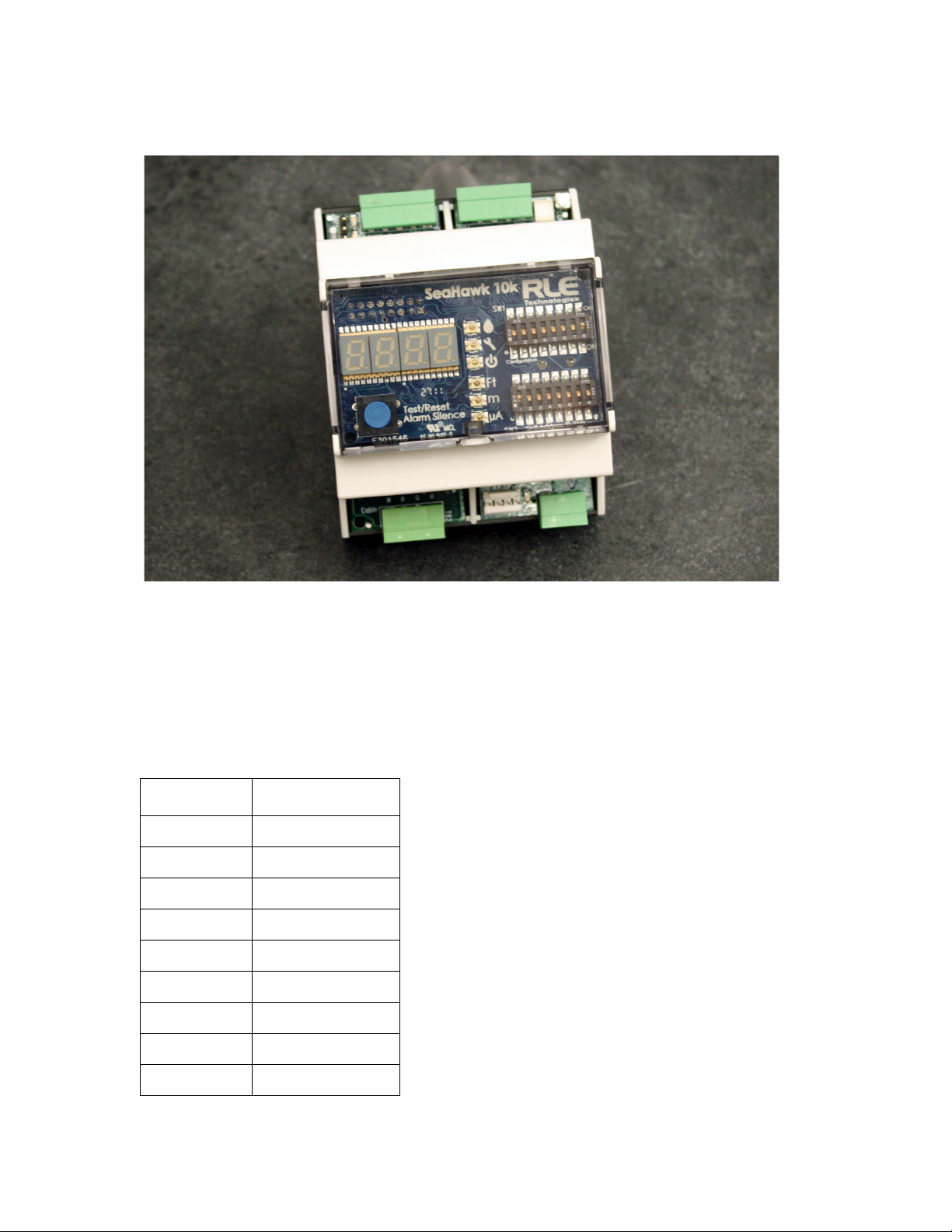
1.1. Description
As RLE’s most cost effective distance-read leak detection solution, the SeaHawk 10K reports
the presence of water and other liquids as detected by sensing cable.
Capable of accommodating up to 10,000 feet (3048m) of sensing cable, the SeaHawk 10K has
an audible alarm and can communicate via Modbus. As a stand-alone solution, the
SeaHawk 10K provides alarm notification and numeric distances on its front panel.
Integration into a Modbus network allows the activity and status of one or multiple
SeaHawk 10Ks to be managed from one central location.
C HAPTER
CHAPTER 0PRODUCT OVERVIEW
1.2. Operation
Supervised System
The SeaHawk 10K is a supervised system – it continually monitors sensing cable and spot
detectors for continuity – and produces alarms for the following conditions:
♦ Leak detection
♦ Cable break
♦ Cable contamination
Distance-Read Leak Detection
When the SeaHawk 10K's circuitry measures a current in excess of the user-defined leak
threshold, the unit's microprocessor computes the distance to the leak. The SeaHawk 10K then
annunciates the leak and communicates via Modbus to a master controller or a Modbusequipped monitoring system. The summary relay sends notification to an alarm panel or
monitoring system.
rletech.com SeaHawk 10K User Guide 11
Page 12

1 Product Overview
User Configuration and Communication
The SeaHawk 10K’s front panel display – which includes a four-digit LED panel and six LED
indicators – provides information about its status, including the following:
♦ Leak detected
♦ Cable fault detected
♦ Power status
♦ Configured unit of measure
♦ Leak detection cable’s amperage value
♦ Distance to leak or contamination
♦ Length of installed leak detection cable
♦ Self-test results
The two blocks of DIP switches on the SeaHawk 10K’s front panel are used for configuration.
DIP SW1 configures parameters such as leak and contamination thresholds, latching alarms,
and realarm time interval. DIP SW2 is used to set the Modbus address information for the unit.
The SeaHawk 10K also provides configuration capability and status information to a Modbus-
equipped system via its EIA-485 port.
12 SeaHawk 10K User Guide 800.518.1519
Page 13

CHAPTER 0INSTALLATION AND CONFIGURATION
2.1. Prepare for Installation
To install the SeaHawk 10K, you’ll need following supplies:
Included with the SeaHawk 10K
C HAPTER
♦ 15 foot (4.57m) leader cable
♦ End-of-line terminator (EOL)
Available from RLE, sold separately
♦ 12-24 VAC/VDC, 50-60Hz isolated power supply
♦ SeaHawk Sensing Cable, up to 10,000 feet (3048m)
♦ J-Clips
Available from other vendors
♦ Electrostatic discharge (ESD) protection
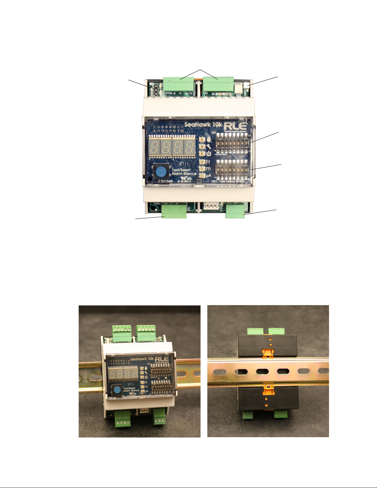
2.2. Physical Connection Overview
The SeaHawk 10K contains two circuit boards:
♦ The top circuit board houses operational controls and displays. SeaHawk 10K operational
information is found in Chapter 3.
♦ The lower circuit board houses the connectors for:
– AC/DC power
– Earth ground
– Relay output
– Leak detection cable
– Communications
rletech.com SeaHawk 10K User Guide 13
Page 14
2 Installation and Configuration
AC/DC Power Connections (2)
and
EIA-485 Communications Ports (2)
Relay
Output
Sensing Cable
Connection
Termination
Jumper
SW1
Configure
Settings
SW2
Modbus
Configuration
EGND1
Earth Ground
for use with
AC Power
Figure 2.1
SeaHawk 10K Physical Inputs
2.3. Mount the SeaHawk 10K
The SeaHawk 10K can be mounted inside a panel or on a DIN rail. The device has two
adjustable orange clips on the bottom. Push the clips out to expose two screw holes that allow
the device to be mounted in a panel; push the clips in to mount it on a DIN rail.
Figure 2.2
14 SeaHawk 10K User Guide 800.518.1519
Mount the SeaHawk 10K
Page 15

2.4. Establish Physical Connections
Relay Output
Sensing Cable
Connection
AC/DC Power Connections (2)
and
EIA-485 Communications Ports (2)
Termination Jumper
Earth Ground
for use with
AC Power
2 Installation and Configuration
Figure 2.3
Figure 2.4
Relay Output (TB1) and Sensing Cable Connection (TB2)
Power and Communications Connections (TB3 and TB4) and Termination Jumper
(JMP)
2.4.1 TB1: Summary Relay (optional)
Terminal Block 1 is a Form C relay output. This relay enables alarm notification through a
local or remote panel, master controller, or BMS whenever a leak, cable fault, or cable
contamination is detected.
1 Insert the wires into the appropriate slots on TB1 to connect the relay output to the desired
panel or controller.
Figure 2.5
rletech.com SeaHawk 10K User Guide 15
Relay Output Connection TB1
Page 16

2 Installation and Configuration
2 DIP switches are used to adjust settings on the SeaHawk 10K.
Figure 2.6
General DIP Switch Settings
Use DIP switch 5 on the SW1 DIP switch block to configure this relay as latched or
unlatched.
♦ An unlatched alarm resets itself once a detected leak or cable problem has been resolved.
♦ A latched alarm must be manually reset, even if the detected leak or cable problem is no
longer present.
Figure 2.7
DIP Switch 5, SW1 - Latched or Unlatched Alarms
2.4.2 TB2: Leader Cable
1 A 15-foot (4.57m) section of non-sensing leader cable is supplied with each SeaHawk 10K.
The leader cable connects sensing cable to the SeaHawk 10K, since sensing cable cannot
connect directly to the unit. Insert its four stripped wires into the appropriate slots in TB2 –
from left to right: white, black, green, and red.
Figure 2.8
Note If the terminal connector is removed from the end of the cable, make sure the wires are in
this same order, W - B - G - R, when the connector is reapplied.
16 SeaHawk 10K User Guide 800.518.1519
Cable Connection TB2
Page 17

2 Installation and Configuration
WARNING
2 Use DIP switch 6 in block SW1 to designate whether the distance on the display is shown in
feet or meters:
Figure 2.9
3
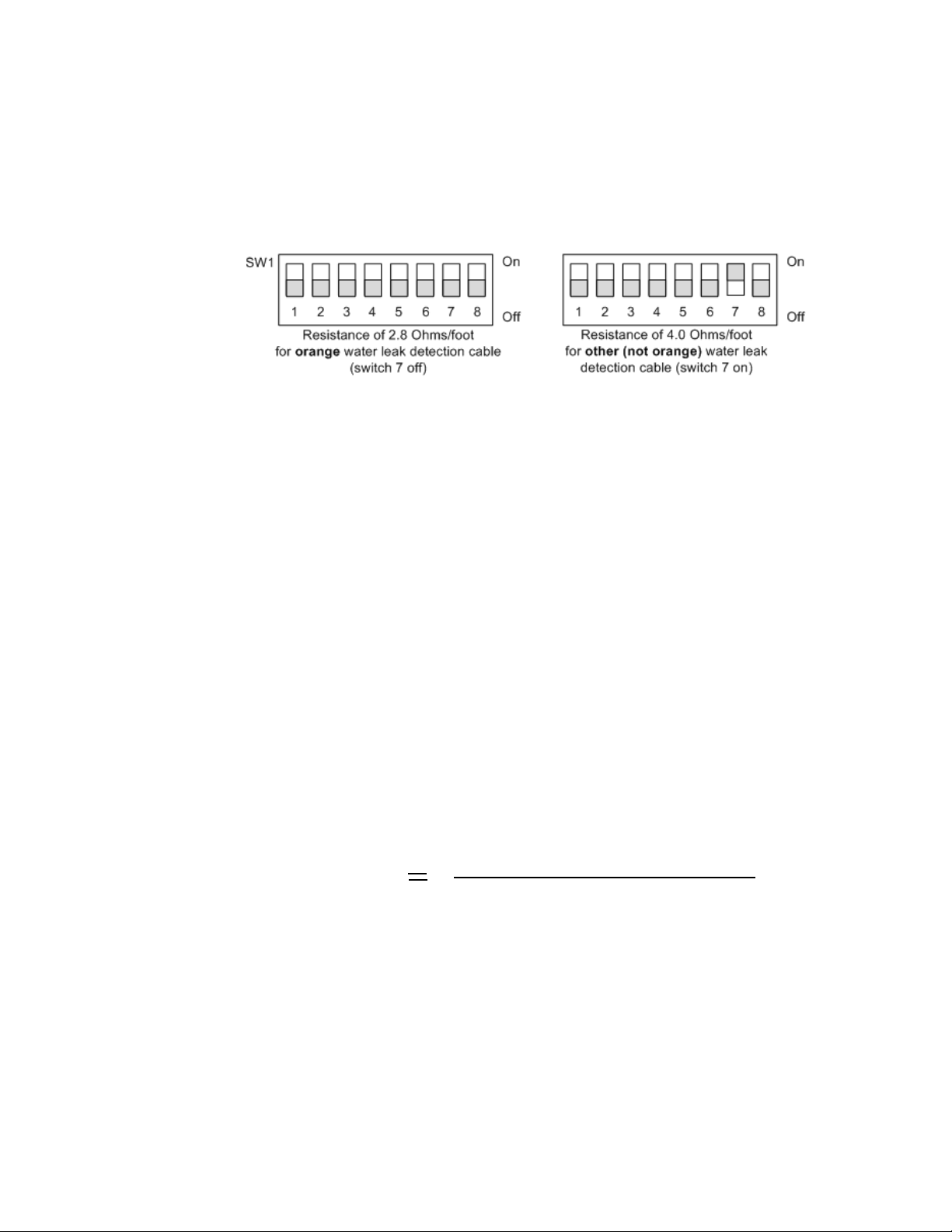
RLE’s orange sensing cable has a resistance of 2.8 ohms per foot. Most other sensing cables
DIP Switch 6, SW1 - Display Cable Length in Feet or Meters
have a resistance of 4.0 ohms per foot. If you have questions regarding the resistance of
your cable, please reference the cable’s data sheet. Set DIP switch 7 in block SW1 to the
appropriate resistance-per-foot value.
Figure 2.10
DIP Switch 7, SW1 - Ohms per Foot Resistance
2.4.3 TB3 and TB4: Input Power and EIA-485 Communications Port
The SeaHawk 10K operates on either 12-24VAC or 12-24VDC power. A power supply is not
included with the SeaHawk 10K.
An isolated power supply must be provided for the SeaHawk 10K.
Do not connect 120/230 VAC to the unit, or damage will occur to the circuitry.
1 Run a power supply to the location of the SeaHawk 10K, or use a DIN rail mountable
power supply and mount it next to the SeaHawk 10K.
2 If you are installing just one SeaHawk 10K, use the two left-most pinouts on either TB3 or
TB4 (marked AC/DC) to connect power to the SeaHawk 10K. Insert the positive and
negative wires of the power supply into either of the pinouts; the SeaHawk 10K’s circuitry
will auto-correct.
If you are installing more than one SeaHawk 10K, use TB3 and TB4 to create a daisychained power connection.
3 If you are installing just one SeaHawk 10K and it will communicate via Modbus to a
Modbus-enabled controller, use the three right-most pinouts on TB3 or TB4 to connect the
SeaHawk 10K to an EIA-485 network.
rletech.com SeaHawk 10K User Guide 17
Page 18

2 Installation and Configuration
If you are installing more than one SeaHawk 10K, use the appropriate pinouts of TB3 and
TB4 to create a daisy-chained Modbus connection.
A grounded shield contact is provided for connection to shielded cable. If the shield contact
is used, verify the power connector is properly grounded and there is no voltage potential
between units on the Modbus network.
Figure 2.11
4
Set the baud rate for the EIA-485 port using DIP switches 1 and 2 on SW1:
Figure 2.12
Note The EIA-485 port is set to 8 databits, no parity, and 1 stop bit (8, N, 1).
TB3 and TB4 Power Supply and Communications Connections
DIP Switch Settings for Communications Baud Rate
18 SeaHawk 10K User Guide 800.518.1519
Page 19
2 Installation and Configuration
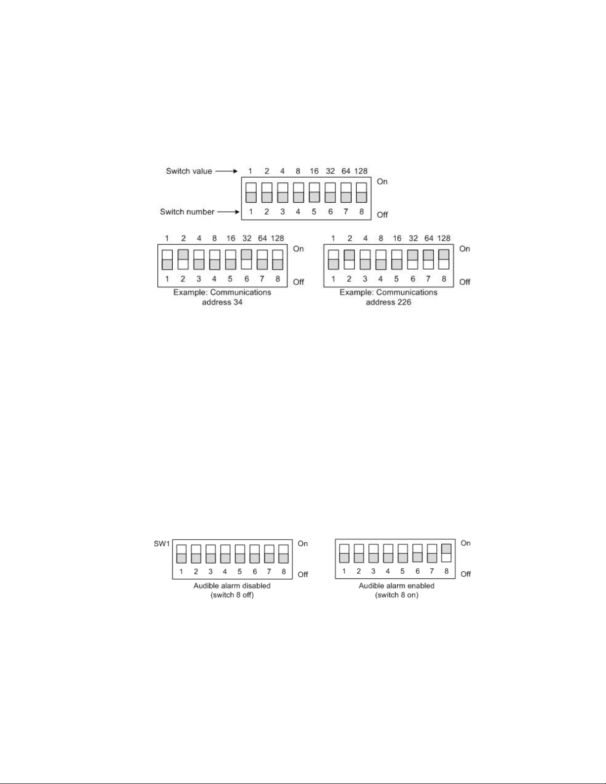
5 DIP SW2 is used to set the Modbus address. For further information regarding Modbus
configuration, refer to Section 4.1., “Modbus Implementation Basics” on page 29.
a If you are communicating via Modbus, you only need to set the Modbus address via
SW2. The Modbus address should be a number between 1 and 254. Adjust the individual
switches until their sum equals the Modbus address. The following illustration shows the
values of the DIP switches on the SW2 block as well as two examples of how the DIP
switches would be set for specific unit addresses.
Figure 2.13
SW2 DIP Switch Settings for Communications Address
2.4.4 JMP - Termination Jumper
The termination jumper, labeled JMP, is located next to TB4. It is used to designate the end of
the line unit In a daisy chain. The SeaHawk 10K ships with the jumper in the non-terminated
position - over the two pins closest to the device enclosure. If your SeaHawk 10K is the only
device in the application, or if it’s not the last unit in the daisy chain, leave the jumper where it
is. If your unit is the last device in a daisy chain, move the jumper so it is over the two pins
nearest the end of the board.
2.5. Select Alarm Options
2.5.1 Enable and Disable the Audible Alarm
The audible alarm is disabled by default. To modify this setting, adjust switch 8 on DIP SW1:
Figure 2.14
rletech.com SeaHawk 10K User Guide 19
DIP Switch 8, SW 1 - Audible Alarm Settings
Page 20

2 Installation and Configuration
2.5.2 Set the Re-Alarm Interval
The SeaHawk 10K can be set to re-alarm – after a leak or cable fault has been detected, the
alarm will be re-sent at a 4 hour interval until the alarm condition has been resolved. This re-
alarm triggers both the audible alarm and the Modbus readout.
The re-alarm option is disabled by default. Activate the re-alarm setting with DIP switch 4 of
SW1:
Figure 2.15
DIP Switch 4, SW1 - Re-Alarm Interval
2.6. Connect the SeaHawk Leak Detection Cable
IMPORTANT To avoid faulty leak detection readings, connect a minimum length of 35 feet (10.7m) of
sensing cable to the SeaHawk 10K.
The SeaHawk 10K is shipped with a 15-foot (4.57m) leader cable. This leader cable was
connected to the SeaHawk 10K in Section 2.4.2 on page 16. The following directions help you
connect sensing cable to the SeaHawk 10K.
2.6.1 Connect Lengths of Sensing Cable
1 Unscrew the end-of-line (EOL) terminator from the end of the leader cable.
2 Attach the first length of sensing cable to the leader cable. Insert the male pins into the
female connector, and twist the collar on the female side of the connector to secure.
Figure 2.16
3
Route the sensing cable according to your cable layout diagram. Attach additional lengths
SeaHawk Sensing Cable
of sensing cable as necessary.
4 Secure the EOL terminator to the unoccupied end of the last length of sensing cable.
Note If the EOL terminator is not present at the end of the cable run, a cable fault will register.
5
If you are using a reference map, compare it with the actual cable installation. Revise any
discrepancies created through the physical installation of the cable.
20 SeaHawk 10K User Guide 800.518.1519
Page 21

2 Installation and Configuration
2.6.2 Secure Sensing Cable to the Floor
Secure the sensing cable to the floor with either J-clips (RLE part #JC), or one of the other
approved methods shown in Figure 2.17. Available from RLE and designed specifically for
use with sensing cable, J-clips are the manufacturer's recommended installation method.
♦ To avoid contaminating the cable, clean the entire floor as much as possible. Use isopropyl
alcohol to clean the spots on the floor where J-clips will be placed.
♦ Place one J-clip every 5 to 6 feet (1.52 to 1.83m) along the length of the sensing cable and
one at each turn of the cable. Use more J-clips if a tighter configuration is required.
♦ If the cable is installed over an obstruction, clip the cable on both sides, as close to the
obstruction as possible.
♦ The J-clip’s adhesive backing does not work well on porous concrete floors. RLE
recommends using a drop of silicone or another nonconductive adhesive to help secure the
J-clip to the floor.
IMPORTANT Do not install the cable directly in front of an air conditioner. Allow a minimum of 4 to 6 feet
(1.22 to 1.83m) between the unit and the cable. If the cable is too close to the air conditioning
unit’s air stream, the moisture from the humidifier may cause false leak readings. If the cable
must be installed in front of an air conditioning unit, place the J-clips 3 feet (0.91m) apart.
.
Figure 2.17
Secure the Cable
rletech.com SeaHawk 10K User Guide 21
Page 22

2 Installation and Configuration
WARNING
2.7. Apply Power to the SeaHawk 10K
An isolated power supply must be provided for the SeaHawk 10K. In addition, a
dedicated circuit breaker must be provided within close proximity to the
SeaHawk 10K and be clearly marked as the disconnecting device for the
SeaHawk 10K leak detection controller.
Do not connect 120/230 VAC to the unit, or damage will occur to the circuitry.
1 An isolated power supply was run and power was connected to the SeaHawk 10K in
Section 2.4.3 on page 17.
2 Ensure all connections are correct and all screw terminals are secure.
Note For AC power connections, wire EGND1 to Earth ground.
3 Apply power to the SeaHawk 10K. The device will begin to boot.
4 Wait approximately one minute for the SeaHawk 10K to start up. Under normal operating
conditions, the power LED glows green and the LED display reads
5 No alarm should be present. If an alarm is present, consult Chapter 6 for troubleshooting
information.
6 Press the Test/Reset button once to verify the amperage reading. For new leak detection
cable, the amperage will be either 0 or 1 μA. If the current is higher than 0 or 1 μA,
contamination may have been introduced during installation. Clean the floor, and then uses
isopropyl alcohol to clean the cable. If the sensing cable is not new, the reading may be
higher. RLE recommends cleaning the cable is the amperage reading is 15 μA or higher.
7 Press the Test/Reset button twice to verify the length of installed sensing cable. If the length
displayed is different from the actual length installed, consult Chapter 6 for troubleshooting
information.
2.8. Test the System
Note If the SeaHawk 10K is already connected to a BMS or NMS, notify monitoring personnel
before you begin testing the system.
1 To verify the SeaHawk 10K’s accuracy, test three points within the length of sensing cable
- one at the beginning, one in the middle of the length, and another near the end of the
length of cable.
SH10
.
2 There are a variety of ways to simulate a leak.
♦ Pour a small puddle of water on the cable while it rests on the floor.
♦ Dunk the cable in a cup of water.
22 SeaHawk 10K User Guide 800.518.1519
Page 23

♦ Wet a paper towel or rag and wrap it loosely around the cable. This is popular if the cable
is used in pipe applications. Be careful to wrap the wet cloth loosely around the cable. Do
not put pressure on the cable.
IMPORTANT To avoid inaccurate readings, do not grip the cable with your hand.
Verify that the SeaHawk 10K reports the leaks within approximately two feet of their actual
3
physical location.
4 Remove all simulated leak sources and return the system to its normal operating state.
2 Installation and Configuration
rletech.com SeaHawk 10K User Guide 23
Page 24

2 Installation and Configuration
24 SeaHawk 10K User Guide 800.518.1519
Page 25
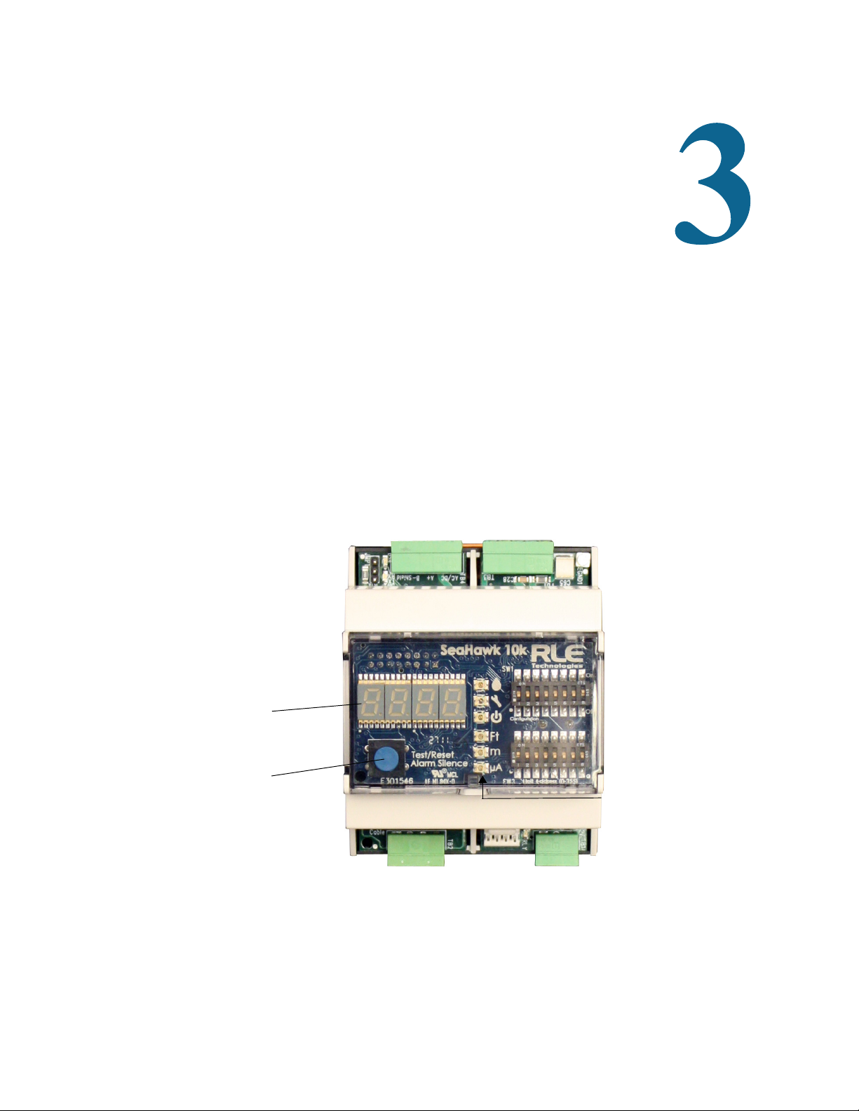
3.1. Front Panel Controls and Display
Four-Character
LED Display
LED
Indicator
Test / Reset /
Alarm Silence
Button
The front panel of the SeaHawk 10K contains a 4-character LED and series of colored LEDs
that are used together to convey device status and information regarding detected leaks and
cable faults. A blue button is used to cycle the 4-character LED, silence the audible alarm, and
reset the alarm.
C HAPTER
CHAPTER 2OPERATION
Figure 3.1
rletech.com SeaHawk 10K User Guide 25
Front Panel Controls and Display
Page 26

3 Operation
Front Panel Indicator Symbol Description
SH10
4-character LED
675
cbr
(e.g.)
• System is running in its normal operating state.
• A leak, fault, or contamination has been detected. The numerical
distance to the leak displays on the LED. A green LED lights next
to the appropriate distance measurement, and either the LED
next to the water drop glows red to indicate a leak, or the LED
next to the wrench glows yellow to indicate cable contamination. If
the distance is measured in meters, a tenths place decimal value
will appear in measurements from 0.0 - 999.9. All meter values
over 1000 will display as whole meter measurements.
• A cable break or fault has been detected. A yellow LED flashes
next to the wrench symbol.
LED
Test/Reset/Alarm
Silence Button
Ft
m
μA
Blue
Push
Button
• Red LED - leak is detected - distance is displayed on 4-
character LED
• Yellow LED - Cable fault - 4-character LED displays
cbr
• Yellow LED - Cable contamination - 4-character LED displays the
distance to the contamination
• Green LED - Power on
• Green LED - Measurements are made in feet
• Green LED - Measurements are made in meters
• Green LED - Microamps of current on cable - amperage is
displayed on 4-character LED
In normal operating conditions, the button functions include:
• Press once: Displays cable current in ohms/foot and the green
LED lights next to the microamp symbol
• Press twice: Displays the length of installed cable components
and the green LED lights next to the appropriate Ft or m symbol
• Press three times: Return to the default display (
SH10
)
• Press and hold: Self-test is initiated and the character display
reads
cal 8060
, which indicates the value of the test resistor.
If an alarm sounds, briefly press the button to turn off the audible
alarm. The Status LED remains red, and the 4-character LED
continues to show the alarm condition.
In an alarm condition, whether the audible alarm is sounding or
not, press and hold this button for 3 seconds to clear the alarm.
Table 3.1
26 SeaHawk 10K User Guide 800.518.1519
Front Panel Controls and Displays
Page 27

3.2. Manage Alarms
General Guidelines
1 If the audible alarm sounds, briefly press the Test/Reset button to silence it.
2 Look at the display, or read the appropriate Modbus register, to determine the type of alarm
and the distance to the leak, contamination, or cable break.
3 If you have a leak detection reference map, cross-reference the distance with the map.
4 Fix the problem (fix the leak, then dry the area and the section of cable involved in the leak;
replace broken cable; clean contaminated cable).
Contamination Alarm Guidelines
If the cable is in a contamination alarm state, check the following:
3 Operation
♦ Verify that the cable is at least 4
feet (1.22m) away from any air conditioning unit.
♦ If there is dirt, grit, or grime on the cable, clean the cable with isopropyl alcohol and a clean
rag.
♦ If the cable is in a high traffic area, move it or install a cable protector over it.
rletech.com SeaHawk 10K User Guide 27
Page 28

3 Operation
28 SeaHawk 10K User Guide 800.518.1519
Page 29

CHAPTER 3MODBUS COMMUNICATION
4.1. Modbus Implementation Basics
The SeaHawk 10K uses its EIA-485 port to communicate via Modbus. The SeaHawk 10K is
configured to act as a slave device on a common network and is a slave only device – it will
never initiate a communications sequence.
C HAPTER
4.1.1 Modes of Transmission
The SeaHawk 10K supports the Modbus RTU mode of transmission, with 8 data bits, no parity
and one stop bit. Every Modbus packet consists of four fields:
♦ Slave Address Field
♦ Function Field
♦ Data Field
♦ Error Check Field (Checksum)
4.1.1.1 Slave Address Field
The slave address field is one byte in length and identifies the slave device involved in the
transaction. The valid Modbus slave address range is between 1 and 254. The Modbus address
was set in Chapter 2, “TB3 and TB4: Input Power and EIA-485 Communications Port” on
page 17. Refer to Figure 2.13, “SW2 DIP Switch Settings for Communications Address” on
page 19 for more specific information.
4.1.1.2 Function Field
The function field is one byte in length and tells the SeaHawk 10K which function to perform.
Functions are 03 (Read 4xxxx output registers) and 04 (Read 3xxxx input registers) are
supported by the SeaHawk 10K.
rletech.com SeaHawk 10K User Guide 29
Page 30

4 Modbus Communication
4.1.1.3 Data Field
The length of the data field varies depending on the function. The data fields for the
SeaHawk 10K are 16-bit registers, transmitted high order byte first (big-endian).
4.1.1.4 Error Check (Checksum) Field
The checksum field lets the receiving device determine if the packet has transmission errors.
The SeaHawk 10K RTU mode uses a 16-bit cyclic redundancy check (CRC-16).
4.1.1.5 5-1.2 Exception Responses
If a Modbus master sends an invalid command to the SeaHawk 10K or attempts to read an
invalid register, an exception response is generated. The response packet will have the high
order bit of the function code set to one. The data field of the exception response contains the
exception error code.
Code Name Description
01 Illegal Function The function code is not supported
02 Illegal Data Address Attempt to access an invalid address
03 Illegal Data Value Attempt to set a variable to an invalid value
Table 4.1
Exception Codes
30 SeaHawk 10K User Guide 800.518.1519
Page 31

4 Modbus Communication
4.2. Packet Communications for the SeaHawk 10K
4.2.1 Function 03: Read Output Registers
To read the SeaHawk 10K parameter values, the master must send a Read Output Registers
request packet.
The Read Output Registers request packet specifies a start register and the number of registers
to read. The start register is numbered from zero (40001 = zero, 40002 = one, etc.).
Read Registers Request Packet Read Registers Response Packet
Slave Address (1 byte) Slave Address (1 byte)
03 (Function code) (1 byte) 03 (Function code) (1 byte)
Start Register (2 bytes) Byte count (1 byte)
# of registers to read (2 bytes) First register (2 bytes)
CRC Checksum (2 bytes) Second register (2 bytes)
…
Cry Checksum (2 bytes)
Table 4.2
Register Name Description Units Range
40001 Leak Threshold Trip point for leak alarm 25-175 uAmps
40002 Contamination
Threshold
40003 Re-alarm Interval
(read-only)
40004 Latched Alarms
(read-only)
Read Output Register Packet Structure
Trip point for
contamination alarm
Amount of time that
passes before unit
resends alarm
notification
Note: Set with DIP SW1;
this register is read-only.
Latched alarm requires
SeaHawk 10K to be
reset once alarm is
cleared.
Note: Set with DIP SW1;
this register is read-only.
Default: 120 uAmps
25-175 uAmps
Default: 50 uAmps
0 (Disabled) or 4 hours
Default: 0 (Disabled)
0 = Disabled
1 = Enabled
Default: Disabled
0-65535
0-65535
0-65535
0-65535
40005 Silence Audible Alarm Indicates whether or not
the audible alarm sounds
when the SeaHawk 10K
goes into alarm state
Table 4.3
rletech.com SeaHawk 10K User Guide 31
Output Registers
0 = Disabled
1 = Enabled
Default: Disabled
0-65535
Page 32

4 Modbus Communication
Register Name Description Units Range
40006 Reset Alarm Resets the
SeaHawk 10K after an
alarm state.
Alternatively, press and
hold the front panel’s
Test/Reset button for 3
seconds.
40007 Sample Size Number of samples
taken to calculate the
leak location
40008 Resistance per Foot Milliohms of resistance
of installed leak
detection cable. This
value is set here and can
also be read through
register 30008.
40009 AC Rejection Frequency Used by ADC to reject
AC powerline
frequencies. Needed
only if the SeaHawk10K
is running on 24VAC
power.
0 = Disabled (do not
reset alarm)
1 = Enabled (reset
alarm)
Default: 0 (Disabled)
0 = Set to default value
4 = Minimum
25 = Maximum
Default: 12
2000 – 3500 Milliohms/
foot*
or
3500 – 4240 Milliohms/
foot*
*to convert this value to
Ohms/foot, divide the
number by 1000
0 = 60Hz
1 = 50Hz
Default: 1 (50Hz)
0-65535
0-65535
0-65535
0-65535
40010 Spare Not used. 0-65535
40011 Spare Not used. 0-65535
40012 Spare Not used. 0-65535
40013 Spare Not used. 0-65535
40014 Spare Not used. 0-65535
40015 Spare Not used. 0-65535
40016 Leak Alarm Delay Amount of time that
5 – 990 seconds
0-65535
passes between leak
40017 Contamination Alarm
Delay
Table 4.3
Output Registers
detection and alarm
notification.
Amount of time that
passes between cable
contamination detection
and alarm notification.
Default: 10 seconds
5 – 990 seconds
Default: 120 seconds
0-65535
32 SeaHawk 10K User Guide 800.518.1519
Page 33
4 Modbus Communication
4.2.2 Function 04: Read Input Registers
To read the SeaHawk 10K input values, the master must send a Read Input Registers request
packet.
The Read Input Registers request packet specifies a start register and the number of registers
to read. The start register is numbered from zero (30001 = zero, 30002 = one, etc).
Read Registers Request Packet Read Registers Response Packet
Slave Address (1 byte) Slave Address (1 byte)
04 (Function code) (1 byte) 04 (Function code) (1 byte)
Start Register (2 bytes) Byte count (1 byte)
# of registers to read (2 bytes) First register (2 bytes)
CRC Checksum (2 bytes) Second register (2 bytes)
…
CRC Checksum (2 bytes)
Table 4.4
Read Input Registers Packet Structure
Register Name Description Units Range
30001 Status Bit level status None 0-65535
30002 Leak Distance Location of leak Ft/Decimeters 0-65535
30003 Units Unit of measure 0=Meters
1=Feet
30004 Leak Current Leakage current on cable μA 0-65535
30005 Cable Length Installed cable length Feet/Decimeters 0-65535
30006 Leg1 Res Resistance of cable
A read-only value, this value
is calculated directly from the
installed leak detection cable.
30007 Leg2 Res Resistance of cable
A read-only value, this value
is calculated directly from the
installed leak detection cable.
30008 Res/Ft Resistance of cable per foot
This value is set through
register 40008
Table 4.5
Input Registers
Ohms 0-65535
Ohms 0-65535
Milliohms*
*to convert this
value to Ohms,
divide the number
by 1000
0-65535
0-65535
rletech.com SeaHawk 10K User Guide 33
Page 34

4 Modbus Communication
Register Name Description Units Range
30009 Version Firmware version x.x.x
(If the register reads
301, the firmware
version is 3.0.1)
38001 Leak Distance Leak distance in meters -
float point - displays with a
tenths place decimal value.
This register must be viewed
and displayed as float
inverse.
38003 Cable Length Cable length in meters - float
point - displays with a tenths
place decimal value. This
register must be viewed and
displayed as float inverse.
Table 4.5
Input Registers (continued)
Bit Description
00 1 = Leak detected
01 1 = Cable break detected
02 1 = Contamination detected
Meters 0.0-9999.9
Meters 0.0-9999.9
0-65535
03 1 = Summary alarm
04-15 Spare
Table 4.6
Status Flags (Register 30001)
4.3. RTU Framing
The example below shows a typical Query/Response from an SeaHawk 10K module.
Register
Slave
Address
02 04 06 00 00 00 00 00 01 B5 A3
Table 4.7
Function
Code
Response Sample
Count Bytes
of Data
Data
Msb Lsb
Slave address 2 responds to Function Code 4 with six bytes of hexadecimal data and ends with
CRC16 checksum.
Register Values:
40001 = 0000 (hex)
40002 = 0000 (hex)
40003 = 0001 (hex)
Register
Data
Msb Lsb
Register
Data
Msb Lsb
CRC
16
“Lsb”
CRC
126
“Msb”
34 SeaHawk 10K User Guide 800.518.1519
Page 35
4.4. Calibrate Cable Length via Modbus
Leg2 Resistance (Modbus register 30007)
(Modbus register 40008)
Resistance per foot
in milliohms/foot
Total Feet of Cable Installed on the System
X
1000
The length of sensing cable connected to the SeaHawk 10K can be calibrated through a
Modbus-enabled system. This helps fine-tune a distance-read leak detection system. If no
alarms are present, follow these steps to calibrate and test the system:
1 Set the SW1 DIP switches for the correct cable resistance per foot, as follows:
4 Modbus Communication
Figure 4.1
2
Press the Test/Reset button on the controller once to verify the cable’s amperage reading.
DIP Switch Settings for Ohms/Foot
Calibration cannot be performed if the current is above 15 μA.
Different sensing cables are cleaned in different ways. The following cleaning instructions
apply to RLE’s orange sensing cable ONLY! If you have questions regarding the care and
maintenance of your sensing cable, please consult the cable’s data sheet or contact the
manufacturer.
If the cable is new and the current is higher than 1 μA, clean the cable. Isopropyl alcohol
removes any contamination that might have been introduced to the cable during installation.
If the cable is older and the amperage reading is above 15 μA, clean the cable. A mild dish
detergent solution removes most dirt. Isopropyl alcohol is also an effective cable cleaner.
3 Sensing cable has a resistance - for example, RLE’s orange cable has a resistance of 2.8
ohms per foot. A system's actual resistance will rarely be exactly 2.8 ohms per foot, but it
will be close - each individual cable or system will vary a very small bit from that 2.8 ohms
per foot value. If you know the exact resistance of your cable, you can fine-tune your
system for a more precise distance reading. The formula for calculating this value - and
more specific directions for using the formula - are as follows:
rletech.com SeaHawk 10K User Guide 35
Figure 4.2
4
Read the Leg 1 and Leg 2 Resistance values in Modbus registers 30006 and 30007. Ensure
Formula for Calculating Exact Cable Resistance
that the reading are similar - within 2% of each other. This helps rule out any major cable
problems before calibration begins. Record the resistance reading from Leg 2, Modbus
register 30007.
Page 36

4 Modbus Communication
Leg2 Resistance (Modbus register 30007)
(Modbus register 40008)
Resistance per foot
in milliohms/foot
Total Feet of Cable Installed on the System
X
1000
2091
750
2788
5 Add up all the lengths of sensing cable and any other equipment in the system that
simulates a length of cable. Record this value. Keep in mind:
♦ Each weighted cable connector (WCCS-50) simulates 50 feet (15.24m) of cable.
♦ Each SD-Z simulates 50 feet (15.24m) of cable.
♦ Each X-Connector (XCON) simulates 150 feet (45.72m) of cable.
6 Divide the Leg 2 resistance by the total length of cable. This value is the resistance of the
cable installed on your system in ohms per foot. This ohms per foot value is for your
reference only (the ohms per foot value will have a decimal point in it, and you cannot write
a number with a decimal point to register 40008). Record this value.
Multiply the value in ohms per foot by 1000. This will give you the value in milliohms per
foot. This milliohms per foot value is your end result, and the number you will write to
Modbus register 40008. Record this value.
7 Access your Modbus-enabled system. Write the milliohms per foot resistance value to the
SeaHawk 10K’s Modbus register 40008.
Example:
♦ The Leg 2 resistance reading on the system is 2091 ohms.
♦ The system has 400 feet of sensing cable,
1 X-Connector - which simulates 150 feet of sensing cable,
4 SD-Zs which simulate 50 feet of cable each, for a total of 200 feet of sensing cable
System-wide, there are 750 feet of actual and simulated cable.
♦ Divide 2091 ohms by 750 feet of cable. You get a resistance of 2.788 ohms per foot.
♦ Multiply 2.789 ohms per foot by 1000 to get 2788 milliohms per foot.
♦ Access Modbus register 40008 and record the new milliohms per foot value, 2788.
36 SeaHawk 10K User Guide 800.518.1519
Page 37

C HAPTER
CHAPTER 4PREVENTIVE MAINTENANCE
Follow these steps monthly to test the SeaHawk 10K and ensure that the device is functioning
properly. If your SeaHawk 10K is hooked into a BMS or NMS, notify monitoring personnel
before you begin to test the system.
1 Place water on the cable - either dip the cable into a cup filled with water, wrap the cable
with a wet cloth, or pour a puddle of water onto the cable.
2 Verify the “leak detected” alarm on the control panel.
3 Compare the distance reading on the SeaHawk 10K to a reference map (if available) to
ensure the SeaHawk 10K displays the correct leak location. See Chapter 4 on page 35 for
more information about calibrating the leak detection cable.
4 Dry the cable and verify the SeaHawk 10K returns to normal.
5 Remove the End-of-Line terminator (EOL).
6 Confirm the “cable break” (
7 Reinstall the EOL.
8 Verify the SeaHawk 10K returns to normal.
9 Monitor the cable current monthly to ensure the cable is not being contaminated. The
cbr
) alarm on the SeaHawk 10K.
SeaHawk 10K will alarm if the contamination is excessive.
10Monitor the cable current. If the cable current is greater than 15μA, troubleshoot the cables
to determine which cable is contaminated. The contaminated cable should be removed,
cleaned, and retested.
rletech.com SeaHawk 10K User Guide 37
Page 38

5 Preventive Maintenance
38 SeaHawk 10K User Guide 800.518.1519
Page 39

C HAPTER
CHAPTER 4TROUBLESHOOTING
Table 6.1
Troubleshooting
Problem Action
Control panel will not
power up
1 Check with a DVOM (multi-meter) for AC or DC input power on the lower left
hand terminal block on the SeaHawk 10K. If no voltage is present at the
terminal block, check the power supply and circuit breaker that power the
SeaHawk 10K. If voltage is present but no LEDs are illuminated, go to step 2.
2 Contact RLE Technologies for further troubleshooting and evaluation.
Cable Break Alarm
1 Verify the leader cable from the sensing cable run is plugged into TB2, the
terminal block marked “Cable.”
2 Verify the End-of-Line terminator (EOL) is installed on the end of the orange
sensing cable run.
3 A section of sensing cable may be damaged or faulty. To isolate a section of
damaged sensing cable, remove the EOL terminator from the end of the cable
run and install it onto the end of the leader cable coming from the control panel.
If the condition clears, there is a damaged/faulty section of sensing cable. Start
moving the EOL terminator to the end of each section of sensing cable to isolate
the faulty section. If you do not find a faulty section of cable and the cable break
alarm does not clear, go to step 4.
4 If the sensing cable is all functional, the leader cable may be damaged or faulty.
To test the leader cable, power down (shut off) the control panel. Remove the
terminal block marked “Cable” from the unit. Remove the four leader cable
wires going into the four position terminal block. Install a jumper wire between
pins 1 and 2 and another jumper wire between pins 3 and 4. Reinstall the
terminal block back into TB2 and reapply power. If the cable break condition
clears, there is a problem with the leader cable. If the condition does not clear,
contact RLE Technologies for further support.
rletech.com SeaHawk 10K User Guide 39
Page 40

6 Troubleshooting
Table 6.1
Troubleshooting (continued)
Problem Action
Control panel does not
calculate the proper
1 Verify the leader cable wires are wired into TB2, the terminal block marked
“Cable,” in the correct order - from left to right, white - black - green - red.
length of cable
2 Calibrate the cable. To do this, adjust the resistance per foot (Configuration
menu via the Web Interface). The control panel is pre-calibrated from the
factory. The overall footage should be within 5% of actual installed length. If the
condition does not change, please contact RLE Technologies
Control panel does not
calculate the proper
leak distance
1 Check to see if multiple leaks are present on the cable. The first leak should be
read and latched by the system; however, if the system is updated, or if two or
more simultaneous leaks occur within 30 seconds of the initial leak, the system
may display an average distance (sum of the distances to all the leaks ÷ the
total number of leaks). If no water is present, continue to step 2.
2 A section of the sensing cable may be faulty. To determine if this is the case:
a Power down the control panel and remove the End-of-Line terminator (EOL)
b Find the junction between the first and second sections of sensing cable.
c Turn power back on at the control panel. Allow the control panel to run for
from the end of the sensing cable.
Separate the two sections and install the EOL terminator at the end of the
first section of sensing cable.
five to ten minutes. Apply a damp cloth, rag or paper towel to the end of the
first section of orange sensing cable. If the leak is calculated correctly,
remove the EOL terminator; reconnect the sensing cable and move down to
the next section of cable.
Persistent Cable
Contamination Alarm
Note Contamination and/or physical damage to the cable is not covered under warranty. For all
other troubleshooting concerns and questions regarding this product, contact RLE
Technologies.
d Repeat this process until a faulty reading is obtained. If the reading is off at
the first section of cable, the SeaHawk 10K may be miscalculating distance.
Please contact RLE Technologies for support.
1 Unless an obvious contaminate can be found, to clear a contamination alarm
the cable must be removed from its installation and cleaned. Usually the cable
can be cleaned by pulling it through a clean damp rag. You can also wipe the
cable with isopropyl alcohol.
2 If the cable is contaminated by oil, glycol or chemicals, the cable can be
washed. Remove the cable from its installation, and submerge in a solution of
one capful mild dish washing detergent to two gallons lukewarm water
(<105°F). Agitate the cable in the solution, rinse with clear lukewarm water and
wipe dry with a clean towel.
3 Connect the cable to the SeaHawk 10K and test it to make sure the
contaminates have been removed before reinstalling the cable under the floor.
40 SeaHawk 10K User Guide 800.518.1519
Page 41

A PPENDIX
CHAPTER 0CONFIGURATION REFERENCE
This chapter provides a complete listing of all possible configuration and address settings that
can be made using the DIP switches in blocks SW1 and SW2.
The configuration of a stand-alone SeaHawk 10K can be performed using the DIP switches on
the front panel. If the SeaHawk 10K will be connected to a Modbus-equipped monitoring
system, some of the configuration can be performed using the registers. Chapter 2 describes
how to install and configure the SeaHawk 10K and refers to specific DIP switch settings
where appropriate. Information about Modbus communications can be found in Chapter 4.
A.1. DIP Switches
The SeaHawk 10K contains two blocks of DIP switches.
Figure A.1
General Dip Switch Settings
rletech.com SeaHawk 10K User Guide 41
Page 42

A Configuration Reference
A.2. DIP SW1 Settings
DIP switch 1 manipulates basic configuration settings on the SeaHawk 10K. Dip switch 3 in
SW1 is unused and should remain in the OFF position.
Figure A.2
42 SeaHawk 10K User Guide 800.518.1519
SW1 Dip Switch Configuration Settings
Page 43

A.3. DIP SW2 Settings
DIP switch 2 is used to set the address of the Modbus device. First, use switches 1 and 2 on
SW1 to set the communication baud rate. Then, use the switches on DIP SW2 as follows for
the communications you plan to employ.
A.3.1 Configure the SeaHawk 10K for Modbus Communications
The Modbus address should be a number between 1 and 254. Adjust the individual switches
until their sum equals the Modbus address. Figure A.3 shows the values of the DIP switches
on the SW2 block as well as two examples of how the DIP switches would be set for specific
unit addresses.
A Configuration Reference
Figure A.3
SW2 DIP Switch Settings for Modbus Unit Address
rletech.com SeaHawk 10K User Guide 43
Page 44

A Configuration Reference
44 SeaHawk 10K User Guide 800.518.1519
 Loading...