


R
R
4
.
RKC INSTRUMENT INC.
®
Temperature Controller
Z100/
Z
00
RS100/RS400
Instruction Manual
IMR02Y03-E1

NOTICE
This manual assumes that the reader has a fundamental knowledge of the principles of
electricity, process control, computer technology and communications.
The figures, diagrams and numeric values used in this manual are only for explanation
purpose.
RKC is not responsible for any damage or injury that is caused as a result of using this
instrument, instrument failure or indirect damage.
RKC is not responsible for any damage and/or injury resulting from the use of instruments
made by imitating this instrument.
Periodic maintenance is required for safe and proper operation of this instrument. Some
components have a limited service life, or characteristics that change over time.
Every effort has been made to ensure accuracy of all information contained herein. RKC
makes no warranty expressed or implied, with respect to the accuracy of the information.
The information in this manual is subject to change without prior notice.
No portion of this document may be reprinted, modified, copied, transmitted, digitized, stored,
processed or retrieved through any mechanical, electronic, optical or other means without
prior written approval from RKC.
Various symbols are used on the equipment, they have the following meaning.
: Alternating current
: Reinforced insulation
: Safety precaution
This symbol is used where the instruction manual needs to be consulted for the safety of
operator and equipment. Carefully read the cautions in this manual before using the
instrument.
Windows is a trademark of Microsoft Corporation.
Modbus is a registered trademark of Schneider Electric.
Company names and product names used in this manual are the trademarks or registered trademarks
of the respective companies.
All Rights Reserved, Copyright 2015, RKC INSTRUMENT INC.

Safety Precautions
Pictorial Symbols (safety symbols)
Various pictorial symbols are used in this manual to ensure safe use of the product, to protect you and
other people from harm, and to prevent damage to property. The symbols are described below.
Be sure you thoroughly understand the meaning of the symbols before reading this manual.
: This mark indicates precautions that must
be taken if there is danger of electric shock,
fire, etc., which could result in loss of life or
injury.
This mark indicates that if these precautions
:
and operating procedures are not taken,
damage to the instrument may result.
: This mark indicates that all precautions
should be taken for safe usage.
To prevent injury to persons, damage to the instrument and equipment, a
suitable external protection device shall be required.
All wiring must be completed before power is turned on to prevent electric
shock, fire or damage to the instrument and equipment.
This instrument must be used in accordance with the specifications to
prevent fire or damage to the instrument and equipment.
This instrument is not intended for use in locations subject to flammable or
explosive gases.
Do not touch high-voltage connections such as power supply terminals, etc.
to avoid electric shock.
RKC is not responsible if this instrument is repaired, modified or
disassembled by other than factory-approved personnel. Malfunction may
occur and warranty is void under these conditions.
IMR02Y03-E1
i-1

This product is intended for use with industrial machines, test and measuring equipment.
(It is not designed for use with medical equipment and nuclear energy plant.)
This is a Class A instrument. In a domestic environment, this instrument may cause radio
interference, in which case the user may be required to take additional measures.
This instrument is protected from electric shock by reinforced insulation. Provide reinforced
insulation between the wire for the input signal and the wires for instrument power supply,
source of power and loads.
Be sure to provide an appropriate surge control circuit respectively for the following:
- If input/output or signal lines within the building are longer than 30 meters.
- If input/output or signal lines leave the building, regardless the length.
This instrument is designed for installation in an enclosed instrumentation panel. All
high-voltage connections such as power supply terminals must be enclosed in the
instrumentation panel to avoid electric shock to operating personnel.
All precautions described in this manual should be taken to avoid damage to the instrument
or equipment.
If the equipment is used in a manner not specified by the manufacturer, the protection
provided by the equipment may be impaired.
All wiring must be in accordance with local codes and regulations.
To prevent instrument damage as a result of failure, protect the power line and the
input/output lines from high currents with a suitable overcurrent protection device with
adequate breaking capacity such as a fuse, circuit breaker, etc.
A malfunction in this product may occasionally make control operations impossible or
prevent alarm outputs, resulting in a possible hazard. Take appropriate measures in the end
use to prevent hazards in the event of malfunction.
Prevent metal fragments or lead wire scraps from falling inside instrument case to avoid
electric shock, fire or malfunction.
Tighten each terminal screw to the specified torque found in the manual to avoid electric
shock, fire or malfunction.
For proper operation of this instrument, provide adequate ventilation for heat dissipation.
Do not connect wires to unused terminals as this will interfere with proper operation of the
instrument.
Turn off the power supply before cleaning the instrument.
Do not use a volatile solvent such as paint thinner to clean the instrument. Deformation or
discoloration will occur. Use a soft, dry cloth to remove stains from the instrument.
To avoid damage to the instrument display, do not rub with an abrasive material or push the
front panel with a hard object.
When disposing of each part used for this instrument, always follows the procedure for
disposing of industrial wastes stipulated by the respective local community.
For Proper Disposal
i-2
IMR02Y03-E1

Symbols
Pictorial Symbols (safety symbols)
: This mark indicates important information on installation,
handling and operating procedures.
: This mark indicates supplemental information on installation,
handling and operating procedures.
: This mark indicates where additional information may be located.
Character Symbols
0 1 2 3 4 5 6 7 8 9
Minus Period
0 1 2 3 4 5 6 7 8 9 - .
A B (b) C c D (d) E F G H I J K
A b C c d E F G H I J K
L M N (n) O (o) P Q (q) R (r) S T t U u
L M n o P q r S T t U u
V W X Y Z
Degree
/
Prime
*
(Asterisk)
V W X Y Z @
Dimly lit
8
Highlighted
8
Flashing
8
Other Symbols
EX
OP
IMR02Y03-E1
: Parameters operatable during the “Expanded display mode”
: Parameters operatable when optional functions are supplied
For the display mode, refer to 9. DISPLAY FUNCTION (P. 9-1).
i-3

NOTICE
Safety Precautions ................................................................................................................ i-1
Pictorial Symbols (safety symbols) ............................................................................... i-1
WARNING ........................................................................................................................ i-1
CAUTION .......................................................................................................................... i-2
For Proper Disposal .............................................................................................................. i-2
Symbols ................................................................................................................................. i-3
Pictorial Symbols (safety symbols) ............................................................................... i-3
Character Symbols ....................................................................................................... i-3
Other Symbols .............................................................................................................. i-3
Contents
1. OUTLINE ............................................................................ 1-1
Page
The chapter 1 describes features, package contents, model code, etc.
1.1 Features ....................................................................................................... 1-2
1.2 Checking the Product ................................................................................... 1-3
1.3 Model Code .................................................................................................. 1-4
Suffix code ................................................................................................................ 1-4
Quick start code 2 (Initial setting code) ..................................................................... 1-7
1.4 Parts Description .......................................................................................... 1-8
Front panel view ....................................................................................................... 1-8
Bottom view .............................................................................................................. 1-9
1.5 Input/Output and Function Blocks ............................................................... 1-10
1.6 Handling Procedure to Operation ............................................................... 1-11
2. MOUNTING ........................................................................ 2-1
The chapter 2 describes mounting cautions, dimensions and mounting procedures.
2.1 Mounting Cautions ........................................................................................ 2-2
2.2 Dimensions ................................................................................................... 2-3
2.3 Procedures of Mounting and Removing ....................................................... 2-4
Mounting position of mounting bracket ..................................................................... 2-4
Mounting procedures (Standard type) ...................................................................... 2-5
Mounting procedures (Waterproof/Dustproof type) [Only RZ100/400]...................... 2-6
Removal procedures ................................................................................................ 2-7
i-4
IMR02Y03-E1

3. WIRING .............................................................................. 3-1
The chapter 3 describes wiring cautions, wiring layout and wiring of terminals.
3.1 Wiring Cautions ............................................................................................ 3-2
3.2 Terminal Layout ............................................................................................ 3-5
RZ100/RS100 ........................................................................................................... 3-5
RZ400/RS400 ........................................................................................................... 3-5
Isolations of input and output .................................................................................... 3-6
3.3 Wiring of Each Terminal ............................................................................... 3-7
Power supply ............................................................................................................ 3-7
Measured input (Thermocouple/RTD) ...................................................................... 3-7
Output 1 (OUT1)/Output 2 (OUT2)/Output 3 (OUT3)................................................ 3-8
Current transformer (CT) input (optional) ............................................................... 3-10
Communication (optional) ....................................................................................... 3-10
Page
3.4 Handling of the Terminal Cover (Optional) ................................................. 3-11
Mounting procedures .............................................................................................. 3-11
Removing procedures ............................................................................................ 3-12
4. BASIC OPERATION AND PARAMETER LIST ................ 4-1
The chapter 4 describes basic operations, different types of modes, switching between modes, and
changing/storing the set values.
4.1 Mode Types and Switching........................................................................... 4-2
4.1.1 Switching between modes ...................................................................................... 4-2
4.1.2 Input type and input range display .......................................................................... 4-3
4.2 Parameter Types and Switching ................................................................... 4-4
4.2.1 Scrolling through parameters .................................................................................. 4-4
4.2.2 Parameter list .......................................................................................................... 4-8
Monitor display mode ............................................................................................... 4-8
SV setting mode ....................................................................................................... 4-8
Communication setting mode ................................................................................... 4-9
Parameter setting mode ......................................................................................... 4-10
Initial setting mode ................................................................................................. 4-12
4.3 Changing Set Value .................................................................................... 4-18
4.4 Protecting Setting Data ............................................................................... 4-19
IMR02Y03-E1
i-5

5. OPERATION ...................................................................... 5-1
The chapter 5 describes Operating precautions, Setup procedures and Parameter setting that are
required before operation.
5.1 Operating Precautions .................................................................................. 5-2
5.2 Setup Procedures ......................................................................................... 5-4
5.3 Initial Setup before Operation ....................................................................... 5-5
5.3.1 Initial setting of setup example 1 (Setting parameters related to the alarm) ............ 5-6
5.3.2 Initial setting of setup example 2
(Setting parameters related to the input, control, output and alarm) ....................... 5-8
5.4 Setting the Control Set Value [Set value (SV)] ........................................... 5-12
5.5 Setting the Alarm Set Value ........................................................................ 5-13
5.6 Tuning the PID Parameters (Execution of AT) ............................................ 5-14
Page
6. INPUT FUNCTION ............................................................. 6-1
The chapter 6 describes input related functions, setting contents and setting procedure based on
the key words related to inputs
.
6.1 Changing Input ............................................................................................. 6-2
6.2 Correcting Input ............................................................................................ 6-7
6.3 Removing Input Noise .................................................................................. 6-8
6.4 Changing Error Handling at Input Error ...................................................... 6-10
7. OUTPUT FUNCTION ......................................................... 7-1
The chapter 7 describes output related functions, setting contents and setting procedure based on
the key words related to outputs.
7.1 Changing Output Assignment ....................................................................... 7-2
7.2 Limiting Output ............................................................................................. 7-6
7.3 Changing Proportional Cycle Time ............................................................... 7-8
7.4 Changing Alarm Output (Energize/De-energize) ........................................ 7-12
7.5 Monitoring Manipulated Output Value ........................................................ 7-15
8. SETTING AND KEY OPERATION .................................... 8-1
The chapter 8 describes display related functions, setting contents and setting procedure based on
the keywords related to setting and key operation.
8.1 Limiting the Setting Range of Set Value (SV) ............................................... 8-2
8.2 Continuing the Control when Entering the Initial Setting Mode ..................... 8-5
8.3 Restricting Key Operation ............................................................................. 8-7
i-6
IMR02Y03-E1

9. DISPLAY FUNCTION ........................................................ 9-1
The chapter 9 describes display related functions, setting contents and setting procedure based on
the key words related to Display.
9.1 Releasing the Display Restriction of the Parameters .................................... 9-2
9.2 Changing the Display Position of STOP during the Control Stop ................. 9-4
9.3 Hiding the Display of the Set Value (SV) ...................................................... 9-6
10. ALARM FUNCTION ....................................................... 10-1
The chapter 10 describes alarm related functions, setting contents and setting procedure based on
the key words related to alarms.
Page
10.1 Using Alarm Function .............................................................................. 10-2
10.1.1 Setting procedure for alarm function ................................................................... 10-2
Setting example: Set the Alarm 1 (Model code: RZ100-MNM*NNN/N) ................ 10-3
10.1.2 Changing alarm type ........................................................................................... 10-8
10.1.3 Setting a differential gap in alarm ac tion ........................................................... 10-14
10.1.4 Preventing alarm from turning on due to a transient abnormal input ................ 10-16
10.1.5 Keeping the alarm state (Interlock function) ...................................................... 10-19
10.1.6 Releasing the alarm state (Interlock release) .................................................... 10-21
10.2 Using Control Loop Break Alarm (LBA) ................................................. 10-23
Setting example: Setting Control loop break alarm (LBA) on Alarm 2
(Model code: RZ100-MNM*NNN/N) ................................................................... 10-24
10.3 Using Heater Break Alarm (HBA) (Optional) .......................................... 10-32
10.3.1 Setting procedure for Heater break al arm (HBA) .............................................. 10-32
Setting example: Set the Heater break alarm 1 (HBA1)
(Model code: RZ100-MNM*TNN/N) ................................................................... 10-33
10.3.2 Setting the heater break alarm (HBA) set value ................................................ 10-38
10.3.3 Changing the current trans former (CT) type ..................................................... 10-40
10.3.4 Preventing Heater break alarm (HBA) from turning on due to
a transient abnormal input ................................................................................ 10-42
10.3.5 Keeping the Heater br eak alarm (HBA) state (Interlock function) ..................... 10-44
10.3.6 Releasing Heater break alarm (HBA) state (Interlock release) ......................... 10-45
10.4 Keeping the Alarm State in STOP Mode ............................................... 10-46
10.5 Checking Alarm ON State ...................................................................... 10-48
IMR02Y03-E1
i-7

11. CONTROL FUNCTION .................................................. 11-1
The chapter 11 describes control related functions, setting contents and setting proce dure based on
the key words related to controls.
11.1 Running/Stopping control (RUN/STOP transfer) ..................................... 11-2
11.2 Changing Control Action .......................................................................... 11-4
11.3 Setting PID Values Automa tically (Autotun i ng) ....................................... 11-8
11.4 Setting PID Values Automatically (Startup tuning) ................................ 11-10
11.5 Setting PID Values Manually .................................................................. 11-14
11.6 Controlling with ON/OFF Action ............................................................. 11-19
11.7 Controlling with Heat/Cool Action .......................................................... 11-24
11.8 Increasing Control Response/Suppressing Overshoot (Fine tuning) ..... 11-29
Page
12. COMMUNICATION FUNCTION (OPTIONAL) .............. 12-1
The chapter 12 describes Host communication including connection, setting, protocol and
communication data.
12.1 Outline ..................................................................................................... 12-2
12.2 Connections ............................................................................................. 12-4
12.2.1 Wiring for host communication ......................................................................... 12-4
12.2.2
12.3 Setting ..................................................................................................... 12-8
12.3.1 Description of each parameter ............................................................................ 12-8
12.3.2 Setting procedure................................................................................................ 12-9
12.3.3 Communication requirements ........................................................................... 12-10
12.4 RKC Communication Protocol ............................................................... 12-12
12.4.1 Polling ............................................................................................................... 12-12
12.4.2 Selecting ........................................................................................................... 12-18
12.5 Modbus Protocol .................................................................................... 12-22
12.5.1 Message format ................................................................................................ 12-22
12.5.2 Function code ................................................................................................... 12-23
12.5.3 Communication mode ....................................................................................... 12-23
12.5.4 Slave responses ............................................................................................... 12-24
12.5.5 Calculating CRC-16 .......................................................................................... 12-25
12.5.6 Register read and write ..................................................................................... 12-28
12.5.7 Caution for handling communication data ......................................................... 12-32
Connections for loader communication (Only RZ100/400) .............................. 12-7
i-8
12.6 Communication Data List ....................................................................... 12-33
12.6.1 Reference to communication data list ............................................................... 12-33
12.6.2 Communication data [RKC communication/Modbus] ........................................ 12-34
IMR02Y03-E1

13. TROUBLESHOOTING ................................................... 13-1
The chapter 13 describes Error displays and countermeasures for errors.
13.1 Error Displays .......................................................................................... 13-2
Input error displays ................................................................................................. 13-2
Self-diagnostic error ............................................................................................... 13-3
13.2 Solutions for Problems ............................................................................. 13-4
Displays .................................................................................................................. 13-5
Control related errors ............................................................................................. 13-6
Operation related errors ......................................................................................... 13-8
Alarm related errors ................................................................................................ 13-8
Control loop break alarm (LBA) related errors ........................................................ 13-9
Heater break alarm (HBA) related errors ................................................................ 13-9
Communication related errors .............................................................................. 13-10
Page
13.3 Verifying Instrument Information ............................................................ 13-12
How to display the information ............................................................................. 13-12
How to check ........................................................................................................ 13-13
14. SPECIFICATIONS ......................................................... 14-1
A. APPENDIX........................................................................ A-1
A.1 Parameters to be Initialized/Changed at the time of changing set values .. A-2
A.1.1 Data to be initialized .............................................................................................. A-2
A.1.2 Data to be automatically converted ....................................................................... A-5
A.2 Replacing the Waterproof/Dustproof Gasket (Option of RZ100/400) ......... A-7
A.3 Current Transformer (CT) Dimensions (Optional) .................................... A-10
A.4 Information about RoHS six hazardous and restricted substances .......... A-11
INDEX [Alphabetical order] ................................................ B-1
INDEX [Character order] ..................................................... B-5
IMR02Y03-E1
i-9

MEMO
IMR02Y03-E1
i-10

OUTLINE
This chapter describes features, package contents, model code, etc.
1.1 Features ........................................................................................... 1-2
1.2 Checking the Product ....................................................................... 1-3
1.3 Model Code ...................................................................................... 1-4
1.4 Parts Description .............................................................................. 1-8
1.5 Input/Output and Function Blocks .................................................. 1-10
1.6 Handling Procedure to Operation ................................................... 1-11
IMR02Y03-E1 1-1

1. OUTLINE
1.1 Features
This high performance digital controller has the following features:
Panel space saving: 60 mm depth (RZ400 and RS400), 63 mm (RZ100 and RS100)
Sampling cycle 0.25 seconds
Incorporates Autotuning (AT) for easy setting of PID values
Automatically calculates the PID values to provide fast stabilization.
“Fine tuning” that changes responsiveness
A new 6 level Fine tuning allows the operator to control response from fast to slow by changing th e Fine tuning setting
(3 to 3) while the PID constant remains unchanged.
Startup tuning eliminates autotuning time
Conventional autotuning time is eliminated by startup tuning which calcu lates optimum PID values immediately upon
startup.
Freely assignable outputs
This instrument can incorporate up to three outputs. Each output port can be freely configured for control outputs
(heating and cooling outputs) and alarm outputs (including heater break alarm outputs).
Easy parameter setup via USB loader port (only RZ100/400)
A user can easily save parameter settings to a PC and copy parameters to other controllers with the USB port, a
COM-K2 converter, and dedicated PROTEM2 software for the RZ100/400.
(Loader communication is available only while RZ100/400 are powered.)
Download the software from the official RKC website:
http://www.rkcinst.com
IP66 waterproof and dustproof protection for severe environments (option of RZ100/400)
Waterproof and dustproof construction (IP66) applies to the front part of the instrument when properly installed on the
panel.
1-2 IMR02Y03-E1

1.2 Checking the Product
Before using this product, check each of the following:
Model code
Check that there are no scratches or breakage in external appearance (case, front panel, or terminal, etc.)
Check that all of the items delivered are complete. (Refer to below)
RZ100/400
Accessories Q’TY Remarks
Instrument 1
Mounting bracket (with screw) 2
RZ100/RZ400 Instruction Manual
(IMR02Y02-E)
1 Enclosed with RZ100/400 (for English)
RS100/400
1. OUTLINE
Accessories Q’TY Remarks
Instrument 1
Mounting bracket (with screw) 2
RS100/RS400 Instruction Manual
(IMR02Y04-X)
1 Enclosed with RS100/400 (for English/Chinese)
Applicable to both models
Accessories Q’TY Remarks
RZ100/RZ400/RS100/RS400
Instruction Manual (IMR02Y03-E1)
Gasket
KRB100-39 (RZ100)
KFB400-36 (RZ400)
Terminal cover
KCA100-517 (RZ100/RS100)
KFB400-58 (RZ400/RS400)
Front cover
KRB100-315 (RZ100/RS100) [Soft cover]
KRB100-36 (RZ100/RS100) [Hard cover]
KRB400-36 (RZ400/RS400) [Hard cover]
CT (Current transformer for heater break alarm)
CTL-6-P-N [for 0 to 30 A] or
CTL-12-S56-10L-N [for 0 to 100 A]
This manual
1
(sold separately)
1 Option of RZ100/400
(Waterproof/Dustproof type)
1 Optional (sold separately)
1 Optional (sold separately)
Depending
on the order
quantity
Option (sold separately)
This manual can be downloaded from
the official RKC website:
http:// www.rkcinst.com/english/
manual_load.htm
IMR02Y03-E1
If any of the above are missing, damaged, or if your manual is incomplete, please contact RKC
sales office or the agent.
1-3

1. OUTLINE
1.3 Model Code
Check that the product received is correctly specified by referring to the following model code list:
If the product is not identical to the specifications, please contact RKC sales office or the agent.
Suffix code
RZ100
RZ400
(1) (2) (3) (4) (5) (6) (7) (8) (9)
Output 1 (OUT1)
Output 2 (OUT2)
Output 3 (OUT3)
Current transformer (CT)
input
(Optional)
Communication function
(Optional)
Waterproof/Dustproof 1
(Optional)
Quick start code
RS100
RS400
-□ □ □*□ □ □ /□-□ □□□
Specification
(1) (2) (3) (4) (5) (6) (7) (8) (9)
None N
Relay contact output M
Voltage pulse output V
Current output (0 to 20 mA DC) 7
Current output (4 to 20 mA DC) 8
None
Relay contact output M
Voltage pulse output V
Current output (0 to 20 mA DC) 7
Current output (4 to 20 mA DC) 8
None N
Relay contact output M
None
CTL-6-P-N (2 points) T
CTL-12-S56-10L-N (2 points) U
None N
RS-485 (RKC communication) 5
RS-485 (Modbus) 6
None
Waterproof/Dustproof (IP66) 1
Quick start code not specified
Specify quick start code 1 3 1
Specify quick start code 1 and 2 2
2
N
Mandatory Optional
N
Suffix code
N
N
Control method
[Quick start code 1]
Measured input and Range
[Quick start code 1]
1
Always “N” for RS100/400.
1-4
No specify quick start code
PID control with AT (Reverse action) F
PID control with AT (Direct action) D
Heat/Cool PID control with AT G
Heat/Cool PID control with AT (for Extruder [air cooling]) A
Heat/Cool PID control with AT (for Extruder [water cooling]) W
No specify quick start code No code
Refer to Input Range Code Table
No code
IMR02Y03-E1

2
If Quick start code is not specified, control action, input range and outputs are factory configured as follows dep ending on with or
without outputs.
With/Without output(s)
Control
Output 1
(OUT1)
1 × - - → F K02
2 × × - → A K02
3 × - × → F K02
4 × × × → A K02
5 - × - → F K02 -
6 - × × → F K02 -
7 - - × → F K02 - -
8 - - - → F K02 - - -
3
If Quick start code 1 is specified, output contents are configured as follows depending on with or without output(s).
×: with output -: without output
(Content of range code is not limited)
Output 1
(OUT1)
1 × - - F or D Specified code →
2 × × - F or D Specified code →
3 × - × F or D Specified code →
4 × × × F or D Specified code →
5 - × - F or D Specified code → -
6 - × × F or D Specified code → -
7 - - × F or D Specified code → - -
8 - - - F or D Specified code → - - -
9 × × -
10 × × ×
×: with output -: without output
Output 2
(OUT2)
With/Without output(s) User specified setting
Output 2
(OUT2)
Output 3
(OUT3)
Output 3
(OUT3)
Control
method
code
G, A or
W
G, A or
W
method
code
Specified code →
Specified code →
Range
code
Range code Output
Output
Control output
Control output
Control output
Control output
(heat-side)
(heat-side)
(heat-side)
(heat-side)
Factory setting
1
(OUT1) Output 2 (OUT2) Output 3 (OUT3)
- -
Control output
(cool-side)
-
Control output
(cool-side)
Alarm 1 output
(Deviation high)
Alarm 1 output
(Deviation high)
Factory setting
1
(OUT1) Output 2 (OUT2) Output 3 (OUT3)
Control output
(heat-side)
Control output
(heat-side)
Control output
(heat-side)
Control output
(heat-side)
Control output
(heat-side)
Control output
(heat-side)
- -
Alarm 1 output
(Deviation high)
-
Alarm 1 output
(Deviation high)
Alarm 1 output
(Deviation high)
Alarm 1 output
(Deviation high)
Control output
(cool-side)
Control output
(cool-side)
-
Alarm 1 output
(Deviation high)
Alarm 1 output
(Deviation high)
-
Alarm 2 output
(Deviation high)
Alarm 1 output
(Deviation high)
Alarm 1 output
(Deviation high)
Alarm 2 output
(Deviation high)
Alarm 2 output
(Deviation high)
Alarm 1 output
(Deviation high)
Alarm 1 output
(Deviation high)
-
-
-
To use alarm output, relay contact output must be specified.
1. OUTLINE
IMR02Y03-E1
1-5

1. OUTLINE
Input Range Code Table
Thermocouple (TC) input RTD input
Input type Code Range Input type Code Range Input type Code Range
K K01 0 to 200 C J JA7 0 to 300 F Pt100 D01 199.9 to 649.0 C
K02 0 to 400 C JB9 328 to 2192 F D02 199.9 to 200.0 C
K03 0 to 600 C JC8 199.9 to 550.0 F D03 100.0 to 50.0 C
K04 0 to 800 C T T01 199.9 to 400.0 C D04 100.0 to 100.0 C
K05 0 to 1000 C T02 199.9 to 100.0 C D05 100.0 to 200.0 C
K06 0 to 1200 C T03 100.0 to 200.0 C D06 0.0 to 50.0 C
K07 0 to 1372 C T04 0.0 to 350.0 C D07 0.0 to 100.0 C
K09 0.0 to 400.0 C T05 199.9 to 300.0 C D08 0.0 to 200.0 C
K10 0.0 to 800.0 C T06 0.0 to 400.0 C D09 0.0 to 300.0 C
K13 0 to 100 C R R01 0 to 1600 C D10 0.0 to 500.0 C
K14 0 to 300 C R02 0 to 1769 C DA1 199.9 to 999.9 F
K17 0 to 450 C R04 0 to 1350 C DA3 199.9 to 200.0 F
K20 0 to 500 C RA1 0 to 3200 F DA4 199.9 to 100.0 F
K41 200 to 1372 C S S01 0 to 1600 C DA5 199.9 to 300.0 F
K43 199.9 to 400.0 C S02 0 to 1769 C DA6 0.0 to 100.0 F
KA1 0 to 800 F B B01 400 to 1800 C DA8 0.0 to 400.0 F
KA2 0 to 1600 F B02 0 to 1820 C DA9 0.0 to 500.0 F
KA3 0 to 2502 F E E01 0 to 800 C DB2 199.9 to 900.0 F
KC8 100.0 to 752.0 F E02 0 to 1000 C JPt100 P01 199.9 to 649.0 C
J J01 0 to 200 C N N01 0 to 1200 C P02 199.9 to 200.0 C
J02 0 to 400 C
J03 0 to 600 C W02 0 to 2320 C P05 100.0 to 200.0 C
J04 0 to 800 C WA1 0 to 4000 F P06 0.0 to 50.0 C
J05 0 to 1000 C PL II A01 0 to 1300 C P07 0.0 to 100.0 C
J06 0 to 1200 C A02 0 to 1390 C P08 0.0 to 200.0 C
J07 199.9 to 300.0 C A03 0 to 1200 C P09 0.0 to 300.0 C
J10 0 to 450 C AA1 0 to 2400 F P10 0.0 to 500.0 C
JA1 0 to 800 F AA2 0 to 2534 F
JA2 0 to 1600 F U U01 199.9 to 600.0 C
JA3 0 to 2192 F L L01 0 to 400 C
JA6 0 to 400 F
W5Re/
W26Re
W01 0 to 2000 C P04 100.0 to 100.0 C
1-6
IMR02Y03-E1

1. OUTLINE
Quick start code 2 (Initial setting code)
Quick start code 2 tells the factory to ship with each parameter preset to the values detailed as specified by
the customer. Quick start code 2 is not necessarily specified when ordering, unless the preset is requested.
These parameters are software selectable items and can be re-programmed in the field following procedures
found in the manual.
□ □ -□ -□ □ -□ □
(A) (B) (C) (D) (E) (F) (G)
Specifications
None N
Deviation high A
Deviation low B
Deviation high/low C
Band D
Deviation high with hold action E
Deviation low with hold action F
Deviation high/low with hold action G
Process high H
Process low J
Alarm 1 type
Alarm 2 type
Control output
assignment
Output assignment of
c
Alarm 1
Output assignment of
Alarm 2 c
Output assignment
of Heater break
alarm 1 c
Output assignment
of Heater break
alarm 2 c
a
Control loop break alarm (LBA) can be specified only for Alarm 2.
b
Control output assignment (code 3 and 4) are available only for Heat/Cool PID control.
c
Alarm output assignment cannot overlap the control output assignment.
Process high with hold action K
Process low with hold action L
Deviation high with re-hold action Q
Deviation low with re-hold action R
Deviation high/low with re-hold action T
Band (High/Low individual setting) U
SV high V
SV low W
Deviation high/low (High/Low individual setting) X
Deviation high/low with hold action (High/Low individual setting) Y
Deviation high/low with re-hold action (High/Low individual setting) Z
Monitor during RUN 4
None N
Alarm 2 (The code is same as Alarm 1 type)
Control loop break alarm (LBA) a 2
PID control: Output 1 (OUT1)
Heat/Cool PID control: Heat-side control output: Output 1 (OUT1)
Cool-side control output: Output 2 (OUT2)
PID control: Output 2 (OUT2)
Heat/Cool PID control: Heat-side control output: Output 2 (OUT2)
Cool-side control output: Output 1 (OUT1)
Heat-side control output: Output 1 (OUT1)
Cool-side control output: Output 3 (OUT3)
Heat-side control output: Output 2 (OUT2)
Cool-side control output: Output 3 (OUT3)
No assignment N
Output 1 (OUT1) 1
Output 2 (OUT2) 2
Output 3 (OUT3) 3
No assignment N
Output 1 (OUT1) 1
Output 2 (OUT2) 2
Output 3 (OUT3) 3
No assignment N
Output 1 (OUT1) 1
Output 2 (OUT2) 2
Output 3 (OUT3) 3
No assignment N
Output 1 (OUT1) 1
Output 2 (OUT2) 2
Output 3 (OUT3) 3
Quick start code 2 (Initial setting code)
(A) (B) (C) (D) (E) (F) (G)
1
2
3 b
4 b
IMR02Y03-E1
1-7

1. OUTLINE
A
A
V
A
A
8
V
A
A
1.4 Parts Description
This section describes various display units and the key functions.
Front Panel View
Measured value (PV) display [Green]
Set value (SV) display [Orange]
Measured value (PV) display [Green]
Set value (SV) display [Orange]
OUT1 to OUT3 lamp [Green]
Set (SET) key
AT lamp [Green]
ALM lamp [Red]
Set (SET) key
RZ100/RS100
PV
888
S
888.8
T OUT1 OUT2
RZ1
00
Shift key
PV
RZ400
OUT3
LM
8888
S
8888
T OUT1 OUT2
Shift key
OUT3
LM
T lamp [Green]
OUT1 to OUT3 lamp [Green]
LM lamp [Red]
Up key Down key
RS400
(Only key appearance is different)
Up key Down key
1-8
IMR02Y03-E1

Display units
Measured value (PV) display [Green] Displays Measured value (PV) or various parameter symbols.
Set value (SV) display [Orange] Displays Set value (SV) or various parameter set values.
Indication lamps
AT lamp [Green]
OUT1 lamp [Green] Lights when Output 1 (OUT1) is turned on.*
OUT2 lamp [Green] Lights when Output 2 (OUT2) is turned on.*
OUT3 lamp [Green] Lights when Output 3 (OUT3) is turned on.*
ALM lamp [Red]
* Lamp indication becomes as follows for current output: For an output of less than 0 %: Extinguished
For an output of more than 100 %: Lit
For an output of more than 0 % but less than 100 %: Dimly lit.
Flashes when Autotuning (AT) is activated. (After AT is completed: AT lamp will go out)
Lights during Startup tuning (ST) execution. (After ST is completed: AT lamp will go out)
Lights when Alarm 1, Alarm 2, Heater break alarm 1 or Heater break alarm 2 is turned on.
Operation keys
Set (SET) key Used for calling up parameters and set value registration.
Shift key
Down key Decreases numerals.
Up key Increases numerals.
Shifts digits when settings are changed.
Used to switch monitor items, RUN/STOP, and modes.
To avoid damage to the instrument, never use a sharp object to press keys.
Bottom View
1. OUTLINE
Loader communication connector is supplied as standard on RZ100/400 only.
RZ100 RZ400
Loader communication connector
Loader communication
connector
(Supplied as standard
on RZ100/400 only)
Setting and monitoring on a personal computer (PC) is possible if the controller is connected with
our cable to a PC via our USB communication converter COM-K2 (sold separately)
Our communication software
(Loader communication is available only while RZ100/400 are powered.)
1
For the COM-K2, refer to the official RKC website.
2
Only available as a download from the official RKC website:
http://www.rkcinst.com
2
must be installed on the PC.
1
.
IMR02Y03-E1
1-9

1. OUTLINE
communicatio
)
)
1.5 Input/Output and Function Blocks
This section describes the input/output and function blocks of the instrument.
Measured
input
TC
RTD
PV monitor
Input processing
PV digital filter
PV bias
CT input
CT1 *
CT2 *
Current value
monitor
Current capture
processing
RUN/STOP transfer
(Front key,
RS-485
Communication
function
*
Protocol selections
Loader
communication
Use our COM-K2 for a connection to a PC.
n
RKC
communication
Modbus
Set value
SV
Control processing
PID control
Heat/Cool PID control
ON/OFF control
Autotuning (AT)
Startup tuning (ST)
Fine tuning
Direct/Reverse action
Output limiter
Alarm processing
Temperature alarm
Heater break alarm
(HBA) *
Control loop break alarm
(LBA)
Monitor during RUN
Communication
processing
Control output
(heat-side)
Control output
(cool-side)
Comprehensive
alarm state
Delay timer
Energized
/De-energized
Interlock release
MV monitor
Output
limiter
Output
limiter
Interlock
(Front key,
communication
Marked
Control output
Alarm output
assignment
Control output
Alarm output
assignment
Control output
Alarm output
assignment
: Monitor display
: Only RZ100/400
*: Optional
Control output
or
Alarm output
Relay contact
Voltage pulse
Current
OUT1
Control output
or
Alarm output
Relay contact
Voltage pulse
Current
OUT2
Control output
or
Alarm output
Relay contact
OUT3
1-10
IMR02Y03-E1

1.6 Handling Procedure to Operation
After installation and wiring, follow the procedure below to configure settings required for operation.
* Change the PID constants manually when the optimum PID constants cannot be calculated by AT or ST because of
characteristic variations of the controlled system.
Power ON
Set operation conditions?
To change pre-set conditions
Initial Setting
Operation Setting
Tuning Type?
Autotuning (AT)
Change from PID to AT
Refer to 11.3 Setting PID Values
Automatically (Autotuning) (P. 11-8).
Refer to 5.6 Tuning the PID Parameters
(Execution of AT) (P. 5-14).
AT lamp flashes
AT End
When the AT is finished, the
controller will automatically
return to PID control.
Conditions specified at time of ordering are acceptable
Refer to 5.3 Initial Setup before Operation (P. 5-5).
Refer to 5.4 Setting the Control Set Value [Set value (SV)] (P. 5-12).
Refer to 5.5 Setting the Alarm Set Value (P. 5-13).
Startup tuning (ST)
ST Setting
ST Execution
During ST execution:
AT lamp lights
AT lamp
turns off
ST End
When the ST is finished, the
controller will automatically
return to PID control.
Operation *
Refer to 11.4 Setting PID Values
Automatically (Startup tuning) (P. 11-10).
AT lamp
turns off
1. OUTLINE
IMR02Y03-E1
1-11

MEMO
1-12 IMR02Y03-E1

MOUNTING
This chapter describes mounting cautions, dimensions and mounting procedure s.
2.1 Mounting Cautions ........................................................................... 2-2
2.2 Dimensions ...................................................................................... 2-3
2.3 Procedures of Mounting and Removing ........................................... 2-4
IMR02Y03-E1 2-1

2. MOUNTING
2.1 Mounting Cautions
To prevent electric shock or instrument failure, always turn off the power before
mounting or removing the instrument.
(1) This instrument is intended to be used under the following environmental conditions. (IEC61010-1)
[OVERVOLTAGE CATEGORY II, POLLUTION DEGREE 2]
(2) Use this instrument within the following environment conditions:
Allowable ambient temperature: 10 to 55 C
Allowable ambient humidity: 5 to 95 %RH
(Absolute humidity: MAX.W.C 29.3 g/m
Installation environment conditions: Indoor use
Altitude up to 2000 m
Short-term temporary overvoltage: 1440 V
Long-term temporary overvoltage: 490 V
3
dry air at 101.3 kPa)
(3) Avoid the following conditions when selecting the mounting location:
Rapid changes in ambient temperature which may cause condensation.
Corrosive or inflammable gases.
Direct vibration or shock to the mainframe.
Water, oil, chemicals, vapor or steam splashes.
Excessive dust, salt or iron particles.
Excessive induction noise, static electricity, magnetic fields or noise.
Direct air flow from an air conditioner.
Exposure to direct sunlight.
Excessive heat accumulation.
(4) Mount this instrument in the panel considering the following conditions:
Provide adequate ventilation space so that heat does not build up.
Ensure at least 50 mm space on top and bottom of the instrument for maintenance and environmental
reasons.
Do not mount this instrument directly above equipment that generates large amount of heat (heaters,
transformers, thyristor units, large-wattage resistors.)
If the ambient temperature rises above 55 C, cool this instrument with a forced air cooling fan, cooling
unit, etc. Cooled air should not blow directly on this instrument.
In order to improve safety and the immunity to withstand noise, mount this instrument as far away as
possible from high voltage equipment, power lines, and rotating machinery.
High voltage equipment: Do not mount within the same panel.
Power lines: Separate at least 200 mm.
Rotating machinery: Separate as far as possible.
For correct functioning mount this instrument in a horizontal position.
(5) If this instrument is permanently connected to equipment, it is important to include a switch or
circuit-breaker into the installation. This should be in close proximity to the equipment and within easy
reach of the operator. It should be marked as the disconnecting device for the equipment.
2-2 IMR02Y03-E1

2. MOUNTING
2.2 Dimensions
Panel thickness: 1 to 10 mm
(When mounting multiple instruments close together, the panel strength should be checked to ensure proper
support.)
RZ100/RS100
L1
L1
45
45
*3
0.6
0
*3
0.6
0
0.6
0
0.6
0
0.6
0
45
25
*4
0.6
0
45
0.8
0
92
30
*4
0.8
0
92
(Unit: mm)
Individual mounting
25
44.8
48
*2
Close horizontal mounting
48
44.8
48.2
63.7
7.9
1
*1
63
79.1
L1 = 48 n 3
n = Number of controllers (2 to 6)
RZ400/RS400
(Unit: mm)
44.8
48
*2
96
91.8
*1
7.9
1
60
70.1
*1 Gasket (optional) [Waterproof/Dustproof] (only RZ100/400)
*2 Terminal cover (optional) [sold separately]
*3 To keep the instrument as waterproof as possible, make sure that the panel surface has no burr or distortion where the hole is to
be cut out.
*4 Remove the gasket. When multiple RZ100/400 are mounted close to one another IP66 water-proof protection will no longer
assured.
Individual mounting
25
Close horizontal mounting
110.6
L1 = 48 n 3
n = Number of controllers (2 to 6)
IMR02Y03-E1
2-3

2. MOUNTING
2.3 Procedures of Mounting and Removing
The mounting position of the mounting brackets
Mounting positions for a single controller
* If mounting brackets are installed on the sides of the Waterproof/Dustproof type controller as shown
in the figure (marked with *), sufficient Waterproof/Dustproof performance cannot be obtained.
RZ100/RS100 RZ400/RS400
Mounting positions for close mounting
RZ100/RS100 RZ400/RS400
When two or more controllers are mounted closely, the optional waterproof/dustproof feature is
no longer assured.
2-4
IMR02Y03-E1

Mounting procedures (Standard type)
2. MOUNTING
1. Prepare the panel cutout as specified in Fig. 2.1.
(Panel thickness: 1 to 10 mm)
Refer to 2.2 Dimensions (P. 2-3).
2. Insert the instrument through the panel cutout. (Fig. 2.2)
3. Insert the mounting bracket into the mounting groove of the
instrument. (Fig. 2.3)
Fig. 2.1
Mounting
holes
Fig. 2.2
Fig. 2.3
Panel
Panel
4. Push the moun ting bracket forward until the bracket is firmly
secured to the panel. (Fig. 2.4)
5. Tighten the screw for the mounting bracket with a Phillips
screwdriver.
Do not overtighten the screw. (Fig. 2.5)
Recommended tightening torque: 0.15 Nm [1.5 kgfcm]
6. The other mounting bracket should be installed in the same
way as described in 3 to 5.
Fig. 2.4
Fig. 2.5
IMR02Y03-E1
2-5

2. MOUNTING
Mounting procedures (Waterproof/Dustproof type) [Only RZ100/400]
The front of the instrument conforms to IP66 [Specify when ordering] when mounted on the panel. For
effective Waterproof/Dustproof, the gasket must be securely placed between the instrument and the panel
without any gap. If gasket is damaged, please contact RKC sales office or the agent.
1. Prepare the panel cutout as specified in Fig. 2.6.
(Panel thickness: 1 to 10 mm)
Refer to 2.2 Dimensions (P. 2-3).
Fig. 2.6
Panel
2. Set the waterproof/dustproof gasket (optional) on the case
from the back side of the instrument as shown in Fig. 2.7.
Insert the instrument through the panel cutout.
3. Insert the mounting bracket into the mounting groove of the
instrument. (Fig. 2.8)
For waterproof and dustproof protection, two
mounting brackets must be placed on the top and
the bottom side of the instrument. If the
mounting brackets are placed on the sides of the
controller, waterproof and dustproof protection
will not be guaranteed.
4. Push the mounting bracket forward until the bracket is
firmly secured to the panel. (Fig. 2.9)
5. Tighten the screw for the mounting bracket with a Phillips
screwdriver.
Do not overtighten the screw. (Fig. 2.10)
Recommended tightening torque: 0.15 Nm [1.5 kgfcm]
6. The other mounting bracket should be installed in the same
way as described in 3 to 5.
For replacing of the gasket, refer to APPENDIX A.2 Replacing the Waterproof/Dustproof
Gasket (Option of RZ100/400) (P. A-7).
Mounting
holes
Fig. 2.7
Gasket
Fig. 2.8
Fig. 2.9
Fig. 2.10
2-6
IMR02Y03-E1

Removal procedures
2. MOUNTING
1. Turn the power OFF.
2. Remove the wiring.
3. Loosen the screw of the mounting bracket.
4. Remove the mounting bracket by pulling it up (Fig. 2.12 )
and forward (Fig. 2.12 ) while holding the rear (Fig. 2.11).
5. The other mounting bracket(s) should be removed in the
same way as described in 3 and 4.
6. Pull out the instrument from the mounting cutout while
holding the front panel frame of this inst r ument. (Fig. 2.13)
Use long-nose pliers to remove mounting brackets
from the instrument that is installed in a narrow place
or installed tightly in a vertical position.
Fig. 2.11
Rear of mounting
bracket
Fig. 2.12
Fig. 2.13
Pull out
Front panel frame
1
2
Panel
IMR02Y03-E1
2-7

MEMO
2-8 IMR02Y03-E1

WIRING
This chapter describes wiring cautions, wiring layout and wiring of terminals.
3.1 Wiring Cautions ................................................................................ 3-2
3.2 Terminal Layout ............................................................................... 3-5
3.3 Wiring of Each Terminal ................................................................... 3-7
3.4 Handling of the Terminal Cover (Optional) ..................................... 3-11
IMR02Y03-E1 3-1

3. WIRING
3.1 Wiring Cautions
To prevent electric shock or instrument failure, do not turn on the power until all wiring
is completed. Make sure that the wiring is correct before applying power to the
instrument.
For thermocouple input, use the appropriate compensation wire.
For RTD input, use low resistance lead wire with no difference in resistance between the three lead wires.
To avoid noise induction, keep input signal wire away from instrument power line, load lines and power
lines of other electric equipment.
If there is electrical noise in the vicinity of the instrument that could affect operation, use a noise filter.
Shorten the distance between the twisted power supply wire pitches to achieve the most effective
noise reduction.
Always install the noise filter on a grounded panel. Minimize the wiring distance between the noise
filter output and the instrument power supply terminals to achieve the most effective noise reduction.
Do not connect fuses or switches to the noise filter output wiring as this will reduce the effectiveness
of the noise filter.
Allow approximately 5 seconds for contact output after the instrument is turned on. Use a delay relay when
the output line is used for an external interlock circuit.
Power supply wiring must be twisted and have a low voltage drop.
This instrument is not provided with an overcurrent protection device (fuse). If a fuse is required for safety,
install a fuse close to the instrument.
Fuse type: Time-lag fuse
Fuse rating: Rated voltage 250 V, Rated current 1 A
Use the solderless terminal appropriate to the screw size.
Screw size: M3 7 (With 5.8 5.8 square washer)
Recommended tightening torque:
Fig. 3.1
φ
5.9 MAX
φ
3.2 MIN
φ 5.0
0.4 N・m (4 kgf・cm)
Applicable wire: Solid/twisted wire of 0.25 to 1.65 mm
Specified dimension: Refer to Fig. 3.1
2
5.6 mm
9.0 mm
Specified solderless terminals:
Circular terminal with isolation V1.25-MS3
(M3 screw, width 5.6 mm, hole diameter 3.2 mm)
Make sure that during field wiring parts of conductors cannot come into contact with adjacent conductive
parts.
3-2 IMR02Y03-E1

3. WIRING
When wiring RZ100/RZ400/RS100/RS400, wire from the left direction toward the backside terminals as
shown in Fig. 3.2.
For RZ100/RS100, the wiring surfaces of the central and the right side lines of terminals are inclined to
make it easier to wire from the left side.
When using the terminal cover (Figs. 3.2, 3.5), it is not possible to wire from the right side.
When wiring from the left and right with a close mounting, there are cases where adjacent instruments
cannot be wired.
Fig. 3.2: Wiring direction
Wire from the left side
(RZ100/RS100)
(RZ100/RS100 is used in the example shown, but the wiring directions are the same for RZ400/RS400.)
When equipped with a terminal cover
(RZ100/RS100)
It is not possible
to wire from the
right side.
Wire from
the left side
Up to two solderless terminal lugs can be connected to one terminal screw.
However, reinforced insulation cannot be assured in this case.
Fig. 3.4: Image of how to bend each solderless terminal lug
(RZ100/RS100)
(RZ100/RS100 is used in the example shown, but restrictions for crossover wiring are the same for RZ400/RS400.)
Panel
Top view
If solderless terminal lugs other than the recommended dimensions are used, terminal screws may
not tighten. In that case, bend each solderless terminal lug before wiring.
If the terminal screw is forcibly tightened, it may be damaged.
In case of RZ100/RS100, if two solderless terminal lugs are connected to one terminal screw, a
terminal cover cannot be used.
IMR02Y03-E1
3-3

3. WIRING
Caution for using the terminal cover:
To prevent electric shock or instrument failure, always turn off the power before mounting or removing
the terminal cover.
When mounting and removing the terminal cover, apply pressure very carefully to avoid damage to the
terminal cover.
If a solderless terminal lug touches the RZ400/RS400 common terminal cover, remove the projection
from the terminal cover by manually bending it back and forth until it breaks off.
(Fig. 3.5)
Fig. 3.5: Image of how to close the terminal board with the terminal cover and to remove projections.
(Only RZ400/RS400)
This section illustrates
how to manually
remove projections
from the terminal
cover if a terminal lug
touches the cover.
RZ400/RS400
Terminal cover
Terminal cover
For the mounting and removing of the terminal cover, refer to 3.4 Handling of the Terminal Cover
(Optional) (P. 3-11).
3-4
IMR02Y03-E1

3.2 Terminal Layout
The terminal layout is as follows.
RZ100/RS100
3. WIRING
Power supply voltage
[Refer to P. 3-7]
100 to 240 V AC
Output 2 (OUT2)
[Refer to P. 3-8]
Relay contact/Voltage pulse/Current
Output 1 (OUT1)
[Refer to P. 3-8]
Relay contact/Voltage pulse/Current
RZ400/RS400
Power supply voltage
[Refer to P. 3-7]
100 to 240 V AC
Output 2 (OUT2)
[Refer to P. 3-8]
Relay contact/Voltage pulse/Current
Output 1 (OUT1)
[Refer to P. 3-8]
Relay contact/Voltage pulse/Current
Unused
Output 3 (OUT3)
[Refer to P. 3-8]
Relay contact
Measured input
[Refer to P. 3-7]
Thermocouple/RTD
To prevent malfunctioning, do not connect wires to unused terminals.
1
2
3
4
5
6
10
11
12
Communication *
[Refer to P. 3-10]
RS-485
713
14
15
16
17
18
Current transformer (CT) input 2 (CT2) *
Current transformer (CT) input 1 (CT1) *
[Refer to P. 3-10]
1
2
3
4
5
6
7
8
9
8
9
10
11
12
* Optional
13
14
15
16
17
18
19
20
21
Unused
Output 3 (OUT3)
[Refer to P. 3-8]
Relay contact
Measured input
[Refer to P. 3-7]
Thermocouple/RTD
Communication *
[Refer to P. 3-10]
RS-485
Unused
22
23
24
* Optional
Current transformer (CT) input 2 (CT2) *
Current transformer (CT) input 1 (CT1) *
[Refer to P. 3-10]
IMR02Y03-E1
3-5

3. WIRING
1
3
Isolations of input and output
For the Input/Output isolation block of this instrument, refer to the following:
Power supply
Isolated
Isolated IsolatedIsolated
MCU
2
Non-Isolated
Output 3
(OUT3)
CT input
(CT1, CT2)
Communication
(RS-485)
3
Isolated
Output 11
(OUT1)
Output 2
(OUT2)
Isolated Isolated
Measured input
Non-Isolated
Loader
communication
1
Outputs are isolated if OUT1 or OUT2 is “relay contact output.” If both outputs are not “relay contact output,” outputs
are not isolated.
2
Loader communication is supplied on RZ100/400 only.
3
Current transformer input and communication are optional functions.
3-6
IMR02Y03-E1

A
12
3.3 Wiring of Each Terminal
Always check the polarity of each terminal prior to wiring.
Power supply
3. WIRING
713
8
9
10
11
12
RZ400/RS400
1
2
3
4
5
6
7
8
9
10
11
12
13
14
15
16
17
18
19
20
21
22
23
24
Connect the power to terminal numbers 1 and 2.
100-240 V AC power supply type
L
C
100-240 V
1
2
N
RZ100/RS100
1
2
14
3
15
4
16
5
17
18
6
Power supply voltage for the controller must be within the range shown below.
Power supply type Power consumption
85 to 264 V AC (including voltage variation)
[Rating: 100 to 240 V AC]
Power supply frequency: 50/60 Hz
RZ100/RS100: 5.1 VA max. (at 100 V AC)
7.6 VA max. (at 240 V AC)
RZ400/RS400: 5.9 VA max. (at 100 V AC)
8.4 VA max. (at 240 V AC)
If there is electrical noise in the vicinity of the instrument that could affect operation, use a noise filter.
Power supply wiring must be twisted and have a low voltage drop.
This instrument is not provided with an overcurrent protection device (fuse). If a fuse is required for safety,
install a fuse close to the instrument.
Fuse type: Time-lag fuse
Fuse rating: Rated voltage 250 V, Rated current 1 A
Measured input (Thermocouple/RTD)
For the measured input type, terminals 10 through 12 are allocated to the measured input.
713
8
9
10
11
12
RZ400/RS400
1
2
3
4
5
6
7
8
9
10
11
12
13
14
15
16
17
18
19
20
21
22
23
24
Thermocouple input
11
TC
12
RTD input
A
RTD
B
B
10
11
RZ100/RS100
1
2
14
3
15
4
16
5
17
18
6
The input types (input group) are as follows.
Input group Input type
Thermocouple (TC) input K, J, T, S, R, E, B, N (JIS C1602-1995), PLII (NBS),
W5Re/W26Re (ASTM-E988-96), U, L (DIN43710-1985)
RTD input Pt100 (JIS C1604-1997),
JPt100 (JIS C1604-1997, JIS C1604-1981 of Pt100)
For thermocouple input, use the appropriate compensation wire.
For RTD input, use low resistance lead wires with no difference in resistance between the three lead wires.
To avoid noise induction, keep input signal wire away from instrument power line, load lines and power
lines of other electric equipment.
IMR02Y03-E1
3-7

3. WIRING
Output 1 (OUT1)/Output 2 (OUT2)/Output 3 (OUT3)
Terminals 5 and 6 are for output 1 (OUT1); Terminals 3 and 4 are for output 2 (OUT2); Terminals 8 and 9
are for output 3 (OUT3).
Connect an appropriate load according to the output type. (Specify when ordering)
Output 2 (OUT2)
Output 1 (OUT1)
Output 1 (OUT1) Outpu t 2 (OUT2) Output 3 (OUT3) Wiring example
OUT
NO
RZ100/RS100
5
6
RZ400/RS400
16
14
15
17
18
NO
713
8
9
10
11
12
OUT
Output 3 (OUT3)
3
4
NO
OUT
Output 2 (OUT2)
Output 1 (OUT1)
Output 3 (OUT3)
8
Load
9
1
2
3
4
5
6
7
8
9
10
11
12
~
13
14
15
16
17
18
19
20
21
22
23
24
OUT
5
NO
6
1
2
3
4
5
6
Relay contact output
Voltage pulse output
OUT
5
6
OUT
3
4
~
SSR Load
OUT
5
0/12 V DC
6
OUT
5
6
Current output
OUT
3
4
~
Actuator Load
: The dotted box diagram describes the output state inside the instrument.
OUT
5
0 to 20 mA DC
6
Outputs are isolated if output 1 (OUT1) or output 2 (OUT2) is “relay contact output.” If both outputs are
“relay contact output,” outputs are not isolated.
Number of outputs and output types must be specified when ordering. The specifications of each output are
as follows.
Specification code
OUT1 OUT2 OUT3
N N N
M M M
V V
7 7
8 8
Output type Specifications
None
Relay contact output Refer to the table on the next page.
Voltage pulse output 0/12 V DC (Allowable load resistance: 500 or more)
Current output
0 to 20 mA DC (Allowable load resistance: 500 or less)
4 to 20 mA DC (Allowable load resistance: 500 or less)
3-8
IMR02Y03-E1

When output type is a relay contact, specification may be different depending on the assigned
output type.
Type Output terminal Output type Specification of relay contact output
RZ100
RS100
RZ400
RS400
RZ400
RS400
RZ100
RS100
RZ400
RS400
Output 1 (OUT1)
Output 2 (OUT2)
Output 3 (OUT3)
Output 3 (OUT3)
Output 1 (OUT1)
Output 2 (OUT2)
Output 1 (OUT1)
Output 2 (OUT2)
Output 3 (OUT3)
Control output
Control output
Alarm output,
Heater break
alarm output
Contact type: 1a contact
Contact rating (Resistive load): 250 V AC
Electrical life: 100,000 times or more (Rated load)
Mechanical life: 20 million times or more
(Switching: 300 times/min)
Contact type: 1a contact
Contact rating (Resistive load): 250 V AC
Electrical life: 300,000 times or more (Rated load)
Mechanical life: 50 million times or more
(Switching: 180 times/min)
Contact type: 1a contact
Contact rating (Resistive load): 250 V AC
Electrical life: 150,000 times or more (Rated load)
Mechanical life: 20 million times or more
(Switching: 300 times/min)
3 A, 30 V DC 1 A
3 A, 30 V DC 1 A
1 A, 30 V DC 0.5 A
It is possible to specify the following uses for output when ordering. (Output reassignment is possible after
the receipt of the delivery.)
Output assignment list [for PID control]
Control output Alarm 1 output Alarm 2 output
No assignment
Output 1 (OUT1) Output 2 (OUT2) or Output 3 (OUT3) *
Output 2 (OUT2) Output 1 (OUT1) or Output 3 (OUT3) *
Any one of outputs 1,2, and 3
(OUT1, 2, 3) *
Heater break alarm 1
(HBA1) output
* Output assignment can be overlapped. Overlapped outputs are produced as OR output.
Heater break alarm 2
(HBA2) output
Not available
3. WIRING
Output assignment list [for Heat/Cool PID control]
Control output
Heat-side output Cool-side output
No assignment No assignment
Output 1 (OUT1) Output 2 (OUT2) Output 3 (OUT3) *
Output 2 (OUT2) Output 1 (OUT1) Output 3 (OUT3) *
Output 1 (OUT1) Output 3 (OUT3) Output 2 (OUT2) *
Output 2 (OUT2) Output 3 (OUT3) Output 1 (OUT1) *
Alarm 1 output Alarm 2 output
Any one of outputs 1,2, and 3
(OUT1, 2, 3) *
* Output assignment can be overlapped. Overlapped outputs are produced as OR output.
Heater break alarm 1
(HBA1) output
Not available
Heater break alarm (HBA) output is an optional function.
Heater break alarm 2
(HBA2) output
IMR02Y03-E1
3-9

3. WIRING
Current transformer (CT) input (optional)
Models that were specified with a current transformer (CT) when ordering can use the following terminal
numbers.
RZ100/RS100: Terminal No. 16 to 18 (CT1, CT2)
RZ400/RS400: Terminal No. 22 to 24 (CT1, CT2)
When using CT input, connect CTs to the relevant terminals.
Current transformer model code: CTL-6-P-N [Input range: 0 to 30 A] (sold separately)
CTL-12-S56-10L-N [Input range: 0 to 100 A] (sold separately)
Current transformer (CT) input is not isolated from the measured input.
RZ100/RS100
CT input
CT2
CT1
COM
RZ400/RS400
CT input
CT2
CT1
COM
RZ100/RS100
1
16
17
18
22
23
24
2
3
4
5
6
RZ400/RS400
1
2
3
4
5
6
7
8
9
10
11
12
713
8
14
9
15
10
16
11
17
12
18
13
14
15
16
17
18
19
20
21
22
23
24
If the current transformer (CT) was replaced, adjust the CT ratio. (Refer to P. 10-40)
Communication (optional)
With Communication function, terminals 13 through 15 are allocated to Communication.
713
8
9
RZ400/RS400
1
2
3
4
5
6
7
8
9
10
11
12
13
14
15
16
17
18
19
20
21
22
23
24
RS-485
SG
T/R (A)
T/R (B)
13
14
15
RZ100/RS100
1
2
14
3
15
4
5
6
10
16
11
17
12
18
For the wiring, refer to 12. COMMUNICATION FUNCTION (P. 12-1).
3-10
IMR02Y03-E1

3.4 Handling of the Terminal Cover (Optional)
When mounting and removing the terminal cover, take the following steps:
To prevent electric shock or instrument failure, always turn off the power before
mounting or removing the terminal cover.
When mounting and removing the terminal cover, apply pressure very carefully to avoid
damage to the terminal cover.
Mounting procedures
3. WIRING
1. Check the mounting direction of the terminal cover.
2. Push the protrusions of terminal cover into the insertion slots for mounting the terminal cover.
Inserting slot
Terminal cover
RZ100/RS100 terminal cover
Protrusions
RZ400/RS400 commo n t e rminal cov e r
Drawing of RZ400/RS400 with terminal caver
Drawing of RZ100/RS100 with terminal caver
This section of RZ400/RS400
terminal cover can be removed
by bending it.
Remove unnecessary part(s)
depending on the wiring
condition.
IMR02Y03-E1
3-11

3. WIRING
Removal procedures
Release the protrusions of terminal cover from the insertion slots () shown in the following figure, and
then pull the terminal cover () to remove it from the case.
3-12
IMR02Y03-E1

BASIC
OPERATION
AND
PARAMETER LIST
This chapter describes basic operations, different types of modes, switching
between modes, and changing/storing the set values.
4.1 Mode Types and Switching .............................................................. 4-2
4.1.1 Switching between modes ................................................................... 4-2
4.1.2 Input type and input range display ....................................................... 4-3
4.2 Parameter Types and Switching ...................................................... 4-4
4.2.1 Scrolling through parameters ............................................................... 4-4
4.2.2 Parameter list ....................................................................................... 4-8
4.3 Changing Set Value ....................................................................... 4-18
4.4 Protecting Setting Data .................................................................. 4-19
IMR02Y03-E1 4-1

4. BASIC OPERATION AND PARAMETER LIST
A
4.1 Mode Types and Switching
4.1.1 Switching between modes
The instrument has five different modes. Modes can be switched through key operations of and
keys.
While pressing the
key, press the key
for 2 seconds or more
While pressing the
key, press the key
for 2 seconds or more
If no key operation is performed within 1 minute in the mode other than Initial setting, the Display
returns to the PV/SV monitor. If no key operation is performed within 1 minute in the Initial setting
mode, the Display returns to the Initial setting code number screen to which it belongs.
Parameters not included in the specification will not be displayed.
Input type/Input range display
Parameters such as Measured
value (PV), Set value (SV), Alarm
status and other parameters can be
monitored in this mode.This screen
is also used to switch between
Control start (RUN) and Stop
(STOP). (Refer to P. 4-8)
Parameter setting mode
Change parameters related to
control such as PID values.
In this mode the instrument can
be configured to meet the
operating requirements.
Power ON
(Refer to P. 4-3)
utomatically (in 4 seconds)
Monitor display mode
2 seconds
or more
(Refer to P. 4-10)
Initial setting mode *
(Refer to P. 4-12)
SV setting mode
In this mode the set value (SV)
can be set. Alarm interlock release
is also possible in this mode.
(Refer to P. 4-8)
While pressing the
key, press the key
While pressing the
key, press the key
Communication setting
2 seconds
or more
2 seconds
or more
While pressing the
key, press the key
for 2 seconds or more
* To enter the Initial setting mode, you need to set the “Setting
data lock” to allow access to the Initial setting mode. For
details, refer to 8.3 Restricting Key Operation (P. 8-7).
mode (optional)
In this mode the optional
communication related function
can be set.
(Refer to P. 4-9)
While pressing the
key, press the key
for 2 seconds or more
4-2 IMR02Y03-E1

4. BASIC OPERATION AND PARAMETER LIST
A
A
4.1.2 Input type and input range display
As soon as this instrument is powered on, input type and input range will be displayed.
Example: When sensor type is K thermocouple (0 to 400 C)
Power ON
PV
0InP
SV
@C0K
utomatically
(in 2 seconds)
Input symbol
Unit for input and SV display:
Temperature input: C or F
Input type symbol
(Refer to table 1)
Table 1: Input type symbol
Symbol Input type
K
J
T
S
PV
Input range high
0400
SV
Input range low
@C00
utomatically
(in 2 seconds)
R
E
b
n
P
W
PV
0428
SV
Monitor display mode
Measured value (PV)/Set value (SV)
monitor
U
L
PT
@C00
JP
Thermocouple K
Thermocouple J
Thermocouple T
Thermocouple S
Thermocouple R
Thermocouple E
Thermocouple B
Thermocouple N
Thermocouple PLII
Thermocouple W5Re/W26 Re
Thermocouple U
Thermocouple L
RTD Pt100
RTD JPt100
IMR02Y03-E1
4-3

4. BASIC OPERATION AND PARAMETER LIST
4.2 Parameter Types and Switching
4.2.1 Scrolling through parameters
The diagram below shows operating navigation.
Power ON
Input type/Input
range display
(Refer to P. 4-3)
Parameters not included in the specification will not be displayed.
(P. 4-8) (P. 4-8)
SV setting mode
Automatically
(in 4 seconds)
モニタ表示モード
Monitor display mode
PV/SV monitor
PV
SV
Comprehensive alarm state
Current transformer 1
(CT1) input value monitor
Current transformer 2
(CT2) input value monitor
Manipulated output value
Manipulated output value
Return to the PV/SV monitor
: Parameters that can be displayed if display requirements are satisfied.
: Parameters displayed in the Expanded display mode.
(The Expanded display mode can be set in the “Display mode selection” in the Initial setting mode.)
: Parameters displayed in the Expanded display mode. (If display requirements are satisfied)
8ALM
8CT1
8CT2
[heat-side]
8MV
[cool-side]
MVc
Return to the PV/SV monitor
For mode switching, refer to 4.1.1 Switching between modes (P. 4-2).
Set value (SV)
828
0000
Dimily lit
Interlock release
Highlighted
(SV can be
changed)
ILr
: Press key
PV
SV
: Press key
(P. 4-9)
Communication setting
mode (optional)
Communication protocol
CMPS
Device address
CAdd
Communication speed
CbPS
Data bit configuration
CbIT
Interval time
CInT
Communication response
monitor
CMrM
Return to the
Communication protocol
4-4
IMR02Y03-E1

A
A
A
A
A
A
[
]
Parameter setting mode
larm 1 set value (ALM1)
larm 1 set value (ALM1) [high]
CAL1
larm 1 set value (ALM1) [low]
AL1`
larm 2 set value (ALM2)
larm 2 set value (ALM2) [high]
CAL2
larm 2 set value (ALM2) [low]
AL2`
Heater break alarm 1
(HBA1) set value
HBA1
Heater break alarm 2
(HBA2) set value
HBA2
Control loop break alarm
(LBA) time
LBA
LBA deadband (LBD)
LBd
Autotuning (AT)
ATU
Startup tuning (ST)
STU
: Parameters that can be displayed if display requirements are satisfied.
: Parameters displayed in the Expanded display mode.
(The Expanded display mode can be set in the “Display mode selection” in the Initial setting mode.)
: Parameters displayed in the Expanded display mode. (If display requirements are satisfied)
For mode switching, refer to 4.1.1 Switching between modes (P. 4-2).
4. BASIC OPERATION AND PARAMETER LIST
key
Cod
0001
: Press key
: Press or
(P. 4-10)
Initial setting mode
Proportional band
[heat-side]
P
Integral time
I
Fine tuning
PTU
Minimum ON/OFF time of
proportioning cycle
[heat-side]
Initial setting code
Code No.: 0000
Cod
0000
(P. 4-12)
Input type
MT
Derivative time
Minimum ON/OFF time of
Anti-reset windup (ARW)
Proportional cycle time
Proportional band
Overlap/Deadband
d
Ar
[heat-side]
T
[cool-side]
Pc
dB
Proportional cycle time
[cool-side]
PV digital filter
t
PV bias
Pb
dF
proportioning cycle
cool-side
Mt
Output limiter high
[Heat-side output limiter (high)]
oLH
Output limiter low
[Cool-side output limiter (high)]
oLL
Set data lock
LCK
Return to the
Alarm 1 set value (ALM1)
InP
Decimal point position
PGdP
Input range high
PGSH
Input range low
PGSL
Alarm 1 type
ALM1
Alarm 2 type
ALM2
Return to the
Initial setting code 0000
IMR02Y03-E1
4-5

4. BASIC OPERATION AND PARAMETER LIST
Cod
0000
Initial setting mode
Initial setting code
Code No.: 0001
Cod
0001
Peak hold monitor of
ambient temperature
Integrated operating time
(upper-digits)
Integrated operating time
(lower-digits)
ROM version
(P. 4-13) (P. 4-13) (P. 4-14) (P. 4-14) (P. 4-15)
TCJ
WTH
WTL
Initial setting code
Code No.: 0002
Cod
0002
Control output assignment
Output assignment of Alarm 1
oAL1
Output assignment of Alarm 2
oAL2
Output assignment of
Heater break alarm 1
oHb1
oCo
813
Output assignment of
Model code monitor
rZ40
Instrument serial number
monitor
JAE0
Return to the
Initial setting code 0001
: Parameters that can be displayed if display requirements are satisfied.
: Parameters displayed in the Expanded display mode.
(The Expanded display mode can be set in the “Display mode selection” in the Initial setting mode.)
: Parameters displayed in the Expanded display mode. (If display requirements are satisfied)
For mode switching, refer to 4.1.1 Switching between modes (P. 4-2).
Heater break alarm 2
oHb2
Output 1 (OUT1)
energize/de-energize
when assigned to alarm
EXC1
Output 2 (OUT2)
energize/de-energize
when assigned to alarm
EXC2
Output 3 (OUT3)
energize/de-energize
when assigned to alarm
EXC3
Return to the
Initial setting code 0002
Initial setting code
Code No.: 0003
Cod
0003
Display mode selection
dSEL
Return to the
Initial setting code 0003
Initial setting code
Code No.: 1021
Cod
1021
Temperature unit
UnIT
Setting limiter high
SLH
Setting limiter low
SLL
PV flashing display
at input error
dSoP
Show/Hide SV display
dSV
Return to the
Initial setting code 1021
: Press key
: Press or
Initial setting code
Code No.: 1030
key
Cod
1030
Action selection
at STOP mode
SS
STOP display selection
SPCH
STOP function
at Initial setting mode
InS
Return to the
Initial setting code 1030
Cod
1041
4-6
IMR02Y03-E1

4. BASIC OPERATION AND PARAMETER LIST
1030
Initial setting mode
Initial setting code
Cod
Alarm 1 differential gap
Alarm 1 interlock
Initial setting code 1041
: Parameters displayed in the Expanded display mode.
(The Expanded display mode can be set in the “Display mode selection” in the Initial setting mode.)
: Parameters displayed in the Expanded display mode. (If display requirements are satisfied)
For mode switching, refer to 4.1.1 Switching between modes (P. 4-2).
Code No.: 1041
Cod
1041
Alarm 1 action
at input burnout
Abo1
Alarm 1 timer
ALT1
AIL1
Return to the
(P. 4-15) (P. 4-15) (P. 4-16) (P. 4-16) (P. 4-17)
AH1
Initial setting code
Code No.: 1042
Cod
1042
Alarm 2 differential gap
AH2
Alarm 2 action
at input burnout
Abo2
Alarm 2 timer
ALT2
Alarm 2 interlock
AIL2
Return to the
Initial setting code 1042
Initial setting code
Code No.: 1045
Cod
1045
CT1 ratio
CTr1
CT2 ratio
CTr2
HBA1 interlock
HIL1
HBA2 interlock
HIL2
HBA determination time
Initial setting code
Code No.: 1051
Cod
1051
Control action
XE
Direct/Reverse action
oS
Cool action
oSc
ON/OFF action
differential gap (upper)
oHH
ON/OFF action
differential gap (lower)
HbT
oHL
Return to the
Initial setting code 1045
Control output at burnout
obo
Return to the
Initial setting code 1051
: Press key
: Press or
Initial setting code 1052
key
Initial setting code
Code No.: 1052
Cod
1052
ST start condition
STS
Return to the
IMR02Y03-E1
4-7

4. BASIC OPERATION AND PARAMETER LIST
4.2.2 Parameter list
Monitor display mode
Symbol Name Display range
ALM
CT1
CT2
MVc
1
Set value (SV) is not displayed in the following cases.
・“SToP” display during STOP is configured to the SV display. (Refer to P. 8-8)
・Set value (SV) is configured to “hide” in setting show/hide SV. (Refer to P. 8-8)
・While error exists.
2
Displayed when any selection other than “None” is selected for Alarm 1 type and Alarm 2 type.
3
Displayed when optional “Current transformer (CT) input” is specified at the time of ordering and the heater break alarm (HBA)
set value is other than “0.0.”
4
Displayed when optional “Current transformer (CT) input” is specified at the time of ordering.
5
Displayed when “Heat/Cool PID control” is specified at the time ordering or when the instrument is configured to “Heat/Cool PID
control” in the selection of the Control action.
PV/SV monitor PV display unit:
Measured range low (5 % of Measured range) to
Measured range high (5 % of Measured range)
For a range with a decimal point, the maximum
display range is 199.9 to 999.9.
SV display unit
Setting limiter low to Setting limiter high
Varies with the setting of the Decimal point position.
Comprehensive alarm state
Current transformer 1 (CT1)
input value monitor 4
Current transformer 2 (CT2)
input value monitor 4
Manipulated output value
MV
[heat-side]
Manipulated output value
[cool-side] 5
Displayed when “Expanded display mode” is selected in the Display mode selection.
2, 3
0: Alarm OFF or No alarm
1: Alarm ON
0000
0.0 to 100.0 A
0.0 to 100.0 A
PID control:
Output limiter low to Output limiter high
Heat/Cool PID control:
5.0 to Heat-side output limiter (high)
5.0 to Cool-side output limiter (high)
1
:
SV display unit
Alarm 1
Alarm 2
Heater break alarm 1 (HBA1)
Heater break alarm 2 (HBA2)
Factory
set value
10-48
10-38
10-38
7-15
7-15
Page
SV setting mode
Symbol Name Data range
1
ILr
1
Not displayed if “Set value (SV): Lock” is selected in the Set data lock. Displays in the following cases.
・“SToP” display during STOP is configured to the SV display. (Refer to P. 8-8)
・Set value (SV) is configured to “hide” in setting show/hide SV. (Refer to P. 8-8)
・While error exists.
2
Displayed when Interlock is used in Alarm 1, 2, or HBA1 or 2.
Set value (SV)
Interlock release 2 oFF: Interlock release
Setting limiter low to Setting limiter high
Varies with the setting of the Decimal point position.
on: Interlock state
4-8
Factory
set value
0 or 0.0 5-12
oFF 10-21
Page
10-45
IMR02Y03-E1
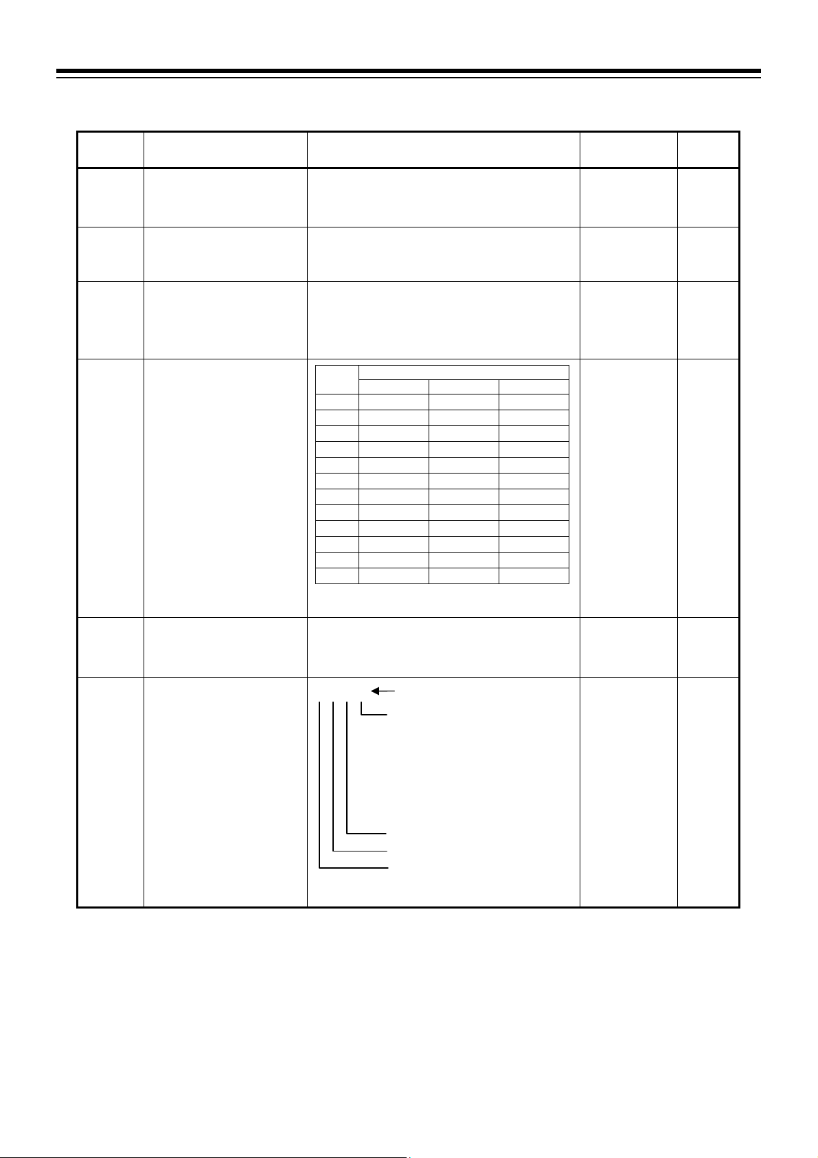
Communication setting mode
4. BASIC OPERATION AND PARAMETER LIST
Symbol Name Data range
CMPS
Add
bPS
bIT
InT
CMrM
1
Displayed when optional “Communication function” is specified at the time of ordering.
2
In Modbus communication, communication is not possible when the address is 0.
3
In Modbus communication, setting 2, 3, 4, 5, 10, or 11 will not establish communication.
4
When two or more errors occur at the same time, the sum of the error numbers are displayed in the hexadecimal format.
Communication protocol 1 0: RKC communication
1: Modbus
Device address 1
Communication speed 1 0: 2400 bps
Data bit configuration 1
Interval time 1 0 to 150 ( 1.666 ms)
Communication response
monitor
1
RKC communication: 0 to 99
Modbus 2: 1 to 99
1: 4800 bps
2: 9600 bps
3: 19200 bps
4: 38400 bps
Setting
0
1
2
3
4
5
6
7
8
9
10
11
Setting range of RKC communication: 0 to 11
Setting range of Modbus
Actual interval time is set value (0 to 150) multiplied
by 1.666 (unit: ms).
0000
* Each time signal is sent or received, 0 and 1 are
displayed in turns.
Data bit configuration
Data bit Parity bit Stop bit
8 Without 1
8 Without 2
7 Even 1
7 Even 2
7 Odd 1
7 Odd 2
8 Even 1
8 Odd 1
8 Even 2
8 Odd 2
7 Without 1
7 Without 2
3
: 0, 1, 6, 7, 8, 9
SV display unit
Communication response monitor 4
0: Normal response
1: Overrun error
2: Parity error
4: Framing error
8: Receive buffer overflow
Errors are displayed in the
hexadecimal format (0 to F).
Unused
Reception status monitor *
Transmission status monitor *
Factory
set value
Communication
Protocol specified
at the time of
ordering.
RKC
communication:
0
Modbus: 1
2 12-8
0 12-8
5 12-8
Page
12-8
12-8
(Example: In case all of four errors occur, a character “F” is displayed)
IMR02Y03-E1
4-9
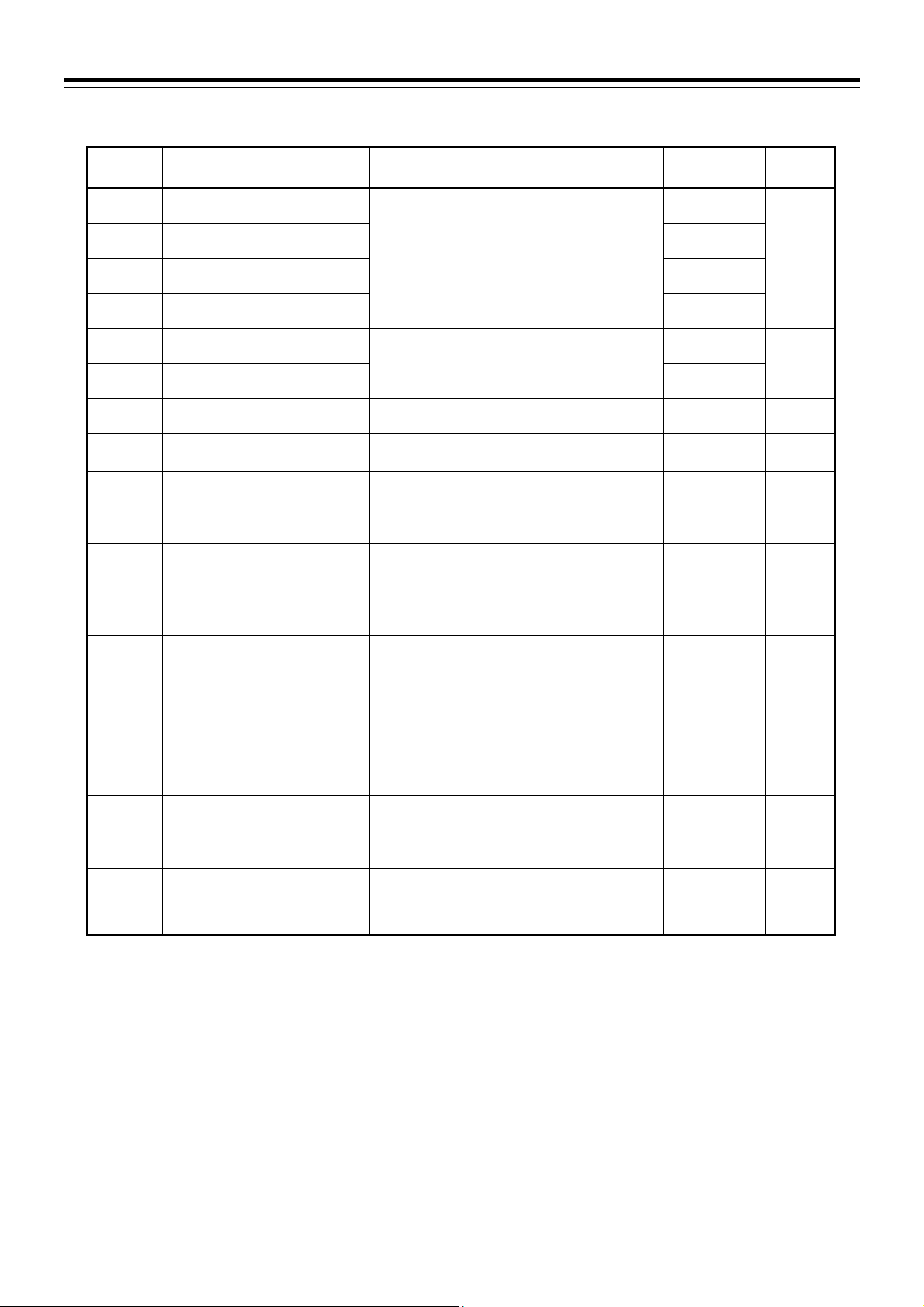
4. BASIC OPERATION AND PARAMETER LIST
Parameter setting mode
Symbol Name Data range
AL1
AL1`
AL2
AL2`
HbA1
HbA2
LbA
Lbd
ATU
STU
1
Displayed when Alarm 1 type is set to the type other than “None” and “Monitor during RUN.”
When “High/Low individual setting type” (setting: 16, 17, 18, 22) is set for Alarm 1 type, “AL1”” becomes Alarm 1 set value
(ALM1) [high].
2
Displayed when Alarm 1 type is set to “High/Low individual setting type” (setting: 16, 17, 18, 22).
3
Displayed when Alarm 2 type is set to the type other than “None,” “Monitor during RUN” and “Control loop break alarm (LBA).”
When “High/Low individual setting type” (setting: 16, 17, 18, 22) is set for Alarm 2 type, “AL2”” becomes Alarm 2 set value
(ALM2) [high].
4
Displayed when Alarm 2 type is set to “High/Low individual setting type” (setting: 16, 17, 18, 22).
5
Displayed when optional “Current transformer (CT) input” is specified at the time of ordering.
6
Displayed when “Control loop break alarm (LBA)” is selected for Alarm 2 type.
7
Displayed when output type (which was configured in control output assignment) is “Relay contact output” or “Voltage pulse
output.”
Alarm 1 set value (ALM1)
Alarm 1 set value (ALM1) [high]
Alarm 1 set value (ALM1) [low] 2 10 or 10.0
Alarm 2 set value (ALM2)
Alarm 2 set value (ALM2) [high]
Alarm 2 set value (ALM2) [low] 4 10 or 10.0
Heater break alarm 1 (HBA1) set
5
value
Heater break alarm 2 (HBA2) set
5
value
Control loop break alarm (LBA)
6
time
LBA deadband (LBD) 6 0 to 9999
Autotuning (AT) 0: PID control
Startup tuning (ST)
Proportional band [heat-side] 0 (0.0) to Input span
P
Integral time 0 to 3600 seconds
I
Derivative time 0 to 3600 seconds
d
Anti-reset windup (ARW) 0 to 100 % of Proportional band [heat-side]
Ar
Proportional cycle time
T
[heat-side]
7
1999 to
1
(Unit: C [F])
Varies with the setting of the Decimal point position.
3
0.0 to 100.0 A
(0.0: HBA function OFF)
0.1 to 200.0 minutes
(Unit: C [F])
1: Start Autotuning (AT)
When the Autotuning (AT) is finished, the control will
automatically return to “0: PID control.”
0: ST unused
1: Execute once *
2: Execute always
* When the Startup tuning (ST) is finished, the control
will automatically return to “0: ST unused.”
(Unit: C [F])
For a scale range with a decimal point, when the input
span exceeds the display limit, the maximum value is
999.9.
Varies with the setting of the Decimal point position.
0 (0.0): ON/OFF action
(0: PD action)
(0: PI action)
(0: Integral action is always OFF)
1 to 100 seconds
9999 or 199.9 to 999.9
Factory
set value
10 or 10.0 5-13
10 or 10.0
0.0 10-32
0.0
8.0 10-23
0 10-29
0 5-14
0 11-10
30 or 30.0 11-14
240 11-14
60 11-14
100 11-14
Relay contact
output: 20
Voltage pulse
output: 2
Continued on the next page.
Page
10-2
10-38
11-8
7-8
4-10
IMR02Y03-E1

4. BASIC OPERATION AND PARAMETER LIST
Symbol Name Data range
Proportional band [cool-side] 1 1 to 1000 % of Proportional band [heat-side]
Pc
db
t
pPb
dF
PTU
MT
Mt
oLH
oLL
LCK
Overlap/Deadband 10 to 10 or 10.0 to 10.0
Proportional cycle time
[cool-side]
PV bias 1999 to 9999 or 199.9 to 999.9
PV digital filter 0 to 100 seconds
Fine tuning 3 to 3
Minimum ON/OFF time of
proportioning cycle
[heat-side] 2
Minimum ON/OFF time of
proportioning cycle
[cool-side]
Output limiter high
[Heat-side output limiter
(high)]
Output limiter low
[Cool-side output limiter
(high)]
Set data lock
1, 2
1, 2
(ON/OFF action of cool-side only is not possible.)
(Unit: C [F])
Varies with the setting of the Decimal point position.
1 to 100 seconds
(Unit: C [F])
Varies with the setting of the Decimal point position.
(0: Digital filter function OFF)
(0: Function OFF)
0 to 1000 ms
0 to 1000 ms
PID control:
Output limiter low to 105.0 %
(Output limiter high Output limiter low)
Heat/Cool PID control:
0.0 to 105.0 %
PID control:
5.0 % to Output limiter high
(Output limiter high Output limiter low)
Heat/Cool PID control:
0.0 to 105.0 %
0000
SV display unit
Parameters in the Parameter setting
mode and the Communication setting
mode excluding the Set value (SV) and
Alarm set values (ALM1, ALM2)
0: Unlock
1: Lock
Alarm set value (ALM1, ALM2)
0: Unlock
1: Lock
Set value (SV)
0: Unlock
1: Lock
Initial setting mode
0: Lock
1: Unlock
Factory
set value
100 11-24
0 or 0.0 11-24
For “Cooling
linear type”
configured to
have “Voltage
pulse output”: 2
Otherwise: 20
0 or 0.0 6-7
1 6-8
0 11-29
0 7-8
0 7-8
105.0 7-6
PID control:
5.0
Heat/Cool PID
control:
105.0
0000 4-19
Page
7-8
7-6
8-7
Displayed when “Expanded display mode” is selected in the Display mode selection.
1
Displayed when “Heat/Cool PID control” is specified at the time ordering or when the instrument is configured to “Heat/Cool PID
control” in the selection of the Control action.
2
Displayed when output type (which was configured in control output assignment) is “Relay contact output” or “Voltage pulse
output.”
IMR02Y03-E1
4-11

4. BASIC OPERATION AND PARAMETER LIST
Initial setting mode
Symbol Name Data range
Cod
InP
PGdP
PGSH
PGSL
ALM1
Initial setting code
0000
Input type
Decimal point position
Input range high (Input range low 1digit) to Measured range high
Input range low Measured range low to (Input range high 1digit)
Alarm 1 type 0: None
This is the first parameter symbol of Initial setting code 0000
0000: TC input K 1000: TC input S
0001: TC input J 1001: TC input B
0010: TC input L 1010: TC input W5Re/W26Re
0011: TC input E 1011: TC input PLII
0100: TC input N 1100: RTD input Pt100
0101: TC input T 1101: RTD input JPt100
0110: TC input U
0111: TC input R
0: No decimal place
1: One decimal place
Setting below zero (first decimal place) is possible if the
selected input type has a measured range with a decimal
place.
Varies with the setting of the Decimal point position.
Varies with the setting of the Decimal point position.
1: Deviation high
2: Deviation high/low
3: Process high
5: Deviation low
6: Band
7: Process low
9: Deviation high with re-hold action
10: Deviation high/low with re-hold action
11: Process high with hold action
13: Deviation low with re-hold action
15: Process low with hold action
16: Deviation high/low (High/Low individual setting)
17: Band (High/Low individual setting)
18: Deviation high/low with re-hold action
(High/Low individual setting)
19: Deviation high with hold action
20: Deviation high/low with hold action
21: Deviation low with hold action
22: Deviation high/low with hold action
(High/Low individual setting)
23: SV high
24: SV low
25: Monitor during RUN
Do not set 4, 8, 12, and 14.
Factory
set value
When input range
code is specified at
the time of ordering,
the input type in the
input range code is
the factory setting.
If input range code is
not specified: 0000
When input range
code is specified at
the time of ordering,
the decimal point
position in the input
range code is
the factory setting.
If input range code is
not specified: 0
When input range
code is specified at
the time of ordering,
the input range high
in the input range
code is the factory
setting.
If input range code is
not specified: 400
When input range
code is specified at
the time of ordering,
the input range low
in the input range
code is the factory
setting.
If input range code is
not specified: 0
When alarm code is
specified at the time
of ordering, the
Alarm type in
the alarm code is
the factory setting.
If Alarm type is not
specified, factory
setting depends on
the specification
(with or without
outputs).
If alarm output is
assigned, Alarm type
is “Deviation high.”
If not assigned,
Alarm type is
“None.”
For details, refer to
1.3 Model Code
(P. 1-4).
Continued on the next page.
Page
6-2
6-2
6-2
6-2
10-8
4-12
IMR02Y03-E1
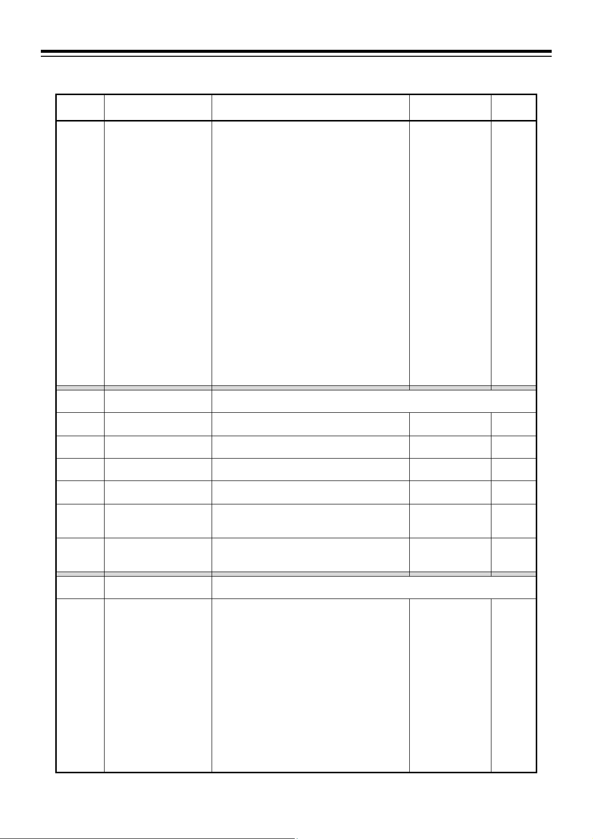
4. BASIC OPERATION AND PARAMETER LIST
Symbol Name Data range
ALM2
Cod
TCJ
WTH
WTL
Cod
oCo
Alarm 2 type 0: None
1: Deviation high
2: Deviation high/low
3: Process high
5: Deviation low
6: Band
7: Process low
9: Deviation high with re-hold action
10: Deviation high/low with re-hold action
11: Process high with hold action
13: Deviation low with re-hold action
15: Process low with hold action
16: Deviation high/low (High/Low individual setting)
17: Band (High/Low individual setting)
18: Deviation high/low with re-hold action
(High/Low individual setting)
19: Deviation high with hold action
20: Deviation high/low with hold action
21: Deviation low with hold action
22: Deviation high/low with hold action
(High/Low individual setting)
23: SV high
24: SV low
25: Monitor during RUN
26: Control loop break alarm (LBA)
Initial setting code
0001
Peak hold monitor of
ambient temperature
Integrated operating time
(upper-digits)
Integrated operating time
(lower-digits)
ROM version PV display: Version number
Model code monitor
Instrument serial number
monitor
Initial setting code
0002
Control output assignment 0: No assignment *
Do not set 4, 8, 12, and 14.
This is the first parameter symbol of Initial setting code 0001
120 to 120 C
0 to 9999 (10000) hours
0 to 9999 hours
SV display: Running number
Model code is displayed.
Display can be scrolled left and right with
the Up/Down keys.
Instrument serial number is displayed.
Display can be scrolled left and right with
the Up/Down keys.
This is the first parameter symbol of Initial setting code 0002
1: PID control: Output 1 (OUT1)
Heat/Cool PID control:
Heat-side output: Output 1 (OUT1)
Cool-side output: Output 2 (OUT2)
2: PID control: Output 2 (OUT2)
Heat/Cool PID control:
Heat-side output: Output 2 (OUT2)
Cool-side output: Output 1 (OUT1)
3: Heat-side output: Output 1 (OUT1)
Cool-side output: Output 3 (OUT3)
4: Heat-side output: Output 2 (OUT2)
Cool-side output: Output 3 (OUT3)
Data range for PID control: 0 to 2
* If “No assignment” is specified, Heater break alarm
(HBA) will be disabled.
Factory
set value
When alarm code is
specified at the time
of ordering,
the Alarm type in
the alarm code is
the factory setting.
If Alarm type is not
specified, factory
setting depends on
the specification
(with or without
outputs).
If alarm output is
assigned, Alarm
type is “Deviation
high.”
If not assigned,
Alarm type is
“None.”
For details, refer to
1.3 Model Code
(P. 1-4).
13-12
13-12
13-12
When Control
output assignment is
specified at the time
of ordering,
the ordered output
assignment is
the factory setting.
If Control output
assignment is not
specified, factory
setting depends on
the specification
(with or without
outputs).
For details, refer to
1.3 Model Code
(P. 1-4).
Continued on the next page.
Page
10-8
7-2
IMR02Y03-E1
4-13

4. BASIC OPERATION AND PARAMETER LIST
Symbol Name Data range
oAL1
oAL2
oHb1
oHb2
EXC1
EXC2
EXC3
Cod
dSEL
Cod
UnIT
SLH
1
Displayed when Alarm 1 type is set to the type other than “None.”
2
Displayed when Alarm 2 type is set to the type other than “None.”
3
Displayed when optional “Current transformer (CT) input” is specified at the time of ordering.
4
Displayed when Heater break alarm 1 (HBA1) set value is set to any value other than “0.0.”
5
Displayed when Heater break alarm 2 (HBA2) set value is set to any value other than “0.0.”
Output assignment of
Alarm 1
Output assignment of
Alarm 2
Output assignment of
Heater break alarm 1
Output assignment of
Heater break alarm 2
Output 1 (OUT1)
energize/de-energize when
assigned to alarm
Output 2 (OUT2)
energize/de-energize when
assigned to alarm
Output 3 (OUT3)
energize/de-energize when
assigned to alarm
Initial setting code
0003
Display mode selection 0: Standard display mode
Initial setting code
1021
Temperature unit 0: C
Setting limiter high
Displayed when “Expanded display mode” is selected in the Display mode selection.
1
2
3, 4
3, 5
1, 2, 3, 4, 5
1, 2, 3, 4, 5
1, 2, 3, 4, 5
0: No assignment
1: Output 1 (OUT1) *
2: Output 2 (OUT2) *
3: Output 3 (OUT3)
* If Output 1 or 2 (OUT1 or 2) is voltage pulse output or
current output, assignment of Alarm output is ignored.
0: No assignment
1: Output 1 (OUT1) *
2: Output 2 (OUT2) *
3: Output 3 (OUT3)
* If Output 1 or 2 (OUT1 or 2) is voltage pulse output or
current output, assignment of Heater break alarm (HBA)
output is ignored.
0: Energize
1: De-energize
(Contact CLOSE or OPEN, at STOP) *
2: De-energize
(Contact OPEN, at STOP)
* If the controller is not in the alarm state at STOP,
contact CLOSE. If the controller is in the alarm state
at STOP, contact OPEN.
This is the first parameter symbol of Initial setting code 0003
1: Expanded display mode
This is the first parameter symbol of Initial setting code 1021
1: F
Setting limiter low to Input range high
Varies with the setting of the Decimal point position.
Factory
set value
When Alarm output
assignment is
specified at the time
of ordering, the
ordered output
assignment is the
factory setting.
If Alarm output
assignment is not
specified, factory
setting depends on
the specification
(with or without
outputs).
For details, refer to
1.3 Model Code
(P. 1-4).
When Heater break
alarm output
assignment is
specified at the time
of ordering,
the ordered output
assignment is
the factory setting.
If Heater break
alarm output
assignment is not
specified: 0
0
0
0
0 9-2
When input range
code is specified at
the time of ordering,
the temperature unit
in the input range
code is the factory
setting.
If input range code
is not specified: 0
Input range high 8-2
Continued on the next page.
Page
7-2
7-2
7-2
7-2
7-12
7-12
7-12
6-2
4-14
IMR02Y03-E1

4. BASIC OPERATION AND PARAMETER LIST
Symbol Name Data range
SLL
dSoP
dSV
Cod
SS
SPCH
InS
Cod
AH1
Abo1
ALT1
AIL1
Cod
AH2
Abo2
ALT2
AIL2
Setting limiter low
PV flashing display at input
error
Show/Hide SV display
Initial setting code
1030
Action selection at STOP
mode
STOP display selection 0: STOP on PV display
STOP function at Initial
setting mode
Initial setting code
1041 1
Alarm 1 differential gap 2 0 to 9999 or 0.0 to 999.9
Alarm 1 action at input
burnout 1
Alarm 1 timer
Alarm 1 interlock 1 oFF: Unused
Initial setting code
1042 3
Alarm 2 differential gap 4 0 to 9999 or 0.0 to 999.9
Alarm 2 action at input
burnout 3
Alarm 2 timer
Alarm 2 interlock 3 oFF: Unused
1
3
Input range low to Setting limiter high
Varies with the setting of the Decimal point position.
0: Flashing display
1: Non-flashing display
0: Show SV
1: Hide SV
This is the first parameter symbol of Initial setting code 1030
0: Alarm is cleared at STOP
1: Alarm remains on at STOP
0000
1: STOP on SV display
0: STOP in the Initial setting mode
1: RUN/STOP continues in the Initial setting mode
This is the first parameter symbol of Initial setting code 1041
(Unit: C [F])
Varies with the setting of the Decimal point position.
0: Alarm output is not forcibly turned ON when the
burnout function is activated.
1: ON at over-scale; no action at underscale
2: ON at underscale; no action at over-scale
3: ON at over-scale or underscale
4: OFF at over-scale or underscale
0 to 600 seconds
on: Used
This is the first parameter symbol of Initial setting code 1042
(Unit: C [F])
Varies with the setting of the Decimal point position.
0: Alarm output is not forcibly turned ON when the
burnout function is activated.
1: ON at over-scale; no action at underscale
2: ON at underscale; no action at over-scale
3: ON at over-scale or underscale
4: OFF at over-scale or underscale
0 to 600 seconds
on: Used
SV display unit
Alarm action
Heater break alarm (HBA) action
0 (fixed) [Do not change this one]
Factory
set value
Input range low 8-2
0 6-10
0 9-6
0000
1
0
2 or 2.0
3
0
oFF 10-21
2 or 2.0
3
0
oFF 10-21
Page
10-46
9-4
8-5
10-14
6-10
10-16
10-14
6-10
10-16
Displayed when “Expanded display mode” is selected in the Display mode selection.
1
Displayed when Alarm 1 type is set to the type other than “None.”
2
Displayed when Alarm 1 is set to the type other than “None” and “Monitor during RUN.”
3
Displayed when Alarm 2 type is set to the type other than “None.”
4
Displayed when Alarm 2 type is set to the type other than “None,” “Monitor during RUN” and “Control loop break alarm (LBA).”
Continued on the next page.
IMR02Y03-E1
4-15

4. BASIC OPERATION AND PARAMETER LIST
Symbol Name Data range
Cod
CTr1
CTr2
HIL1
HIL2
HbT
Cod
oSc
oHH
oHL
1
Displayed when optional “Current transformer (CT) input” is specified at the time of ordering.
2
Displayed when “PID control” is specified for Control action.
3
Displayed when “Heat/Cool PID control” is specified for Control action.
Initial setting code
1045 1
CT1 ratio 1 1 to 1000
CT2 ratio 1 10-40
HBA1 interlock
HBA2 interlock
HBA determination time
Initial setting code
1051
Control action 0: PID control
XE
Direct/Reverse action 2 0: PID control: Direct action
OS
Cool action
ON/OFF action differential
gap (upper)
ON/OFF action differential
gap (lower)
Displayed when “Expanded display mode” is selected in the Display mode selection.
1
1
3
This is the first parameter symbol of Initial setting code 1045
Set the following value depending on the CT type.
CTL-6-P-N: 800
CTL-12-S56-10L-N: 1000
oFF: Unused
on: Used
1
0 to 255 seconds
This is the first parameter symbol of Initial setting code 1051
1: Heat/Cool PID control
1: PID control: Reverse action
0: Heat/Cool PID control: Air cooling (for Extruder)
1: Heat/Cool PID contr o l : Water cooling (for Extruder)
2: Heat/Cool PID control: Cooling linear type
0 to 9999 or 0.0 to 999.9
(Unit: C [F])
Varies with the setting of the Decimal point position.
Factory
set value
When CTL-6-P-N
is specified at the
time or ordering:
800
When
CTL-12-S56-10L-N
is specified at the
time or ordering:
1000
oFF 10-44
3
When control action
is specified at the
time of ordering,
the ordered code for
control action is the
factory setting.
If control action is
not specified,
factory setting
depends on the
specification (with
or without outputs).
For details, refer to
1.3 Model Code
(P. 1-4).
When control action
is specified at the
time of ordering,
the ordered code for
control action is the
factory setting.
If Control action is
not specified: 1
When control action
is specified at the
time of ordering,
the ordered code for
control action is the
factory setting.
If Control action is
not specified: 0
1 or 1.0
Continued on the next page.
Page
10-40
10-44
10-42
11-4
11-4
11-4
11-24
11-19
11-19
4-16
IMR02Y03-E1

4. BASIC OPERATION AND PARAMETER LIST
Symbol Name Data range
obo
Cod
STS
Control output at burnout 0: Result of control computation
1: PID control: Output limiter low (output OFF)
Heat/Cool PID control: 5.0 % (output OFF) *
* Both heating and cooling outputs are forced OFF.
Initial setting code
1052
ST start condition 0: Activate the ST function when the power is
Displayed when “Expanded display mode” is selected in the Display mode selection.
This is the first parameter symbol of Initial setting code 1052
turned on; when transferred from STOP to RUN;
or when the Set value (SV) is changed.
1: Activate the ST function when the power is
turned on; or when transferred from STOP to
RUN.
2: Activate the ST function when the Set value
(SV) is changed.
Factory
set value
PID control:
0
Heat/Cool PID
control:
1
0 11-10
Page
6-10
IMR02Y03-E1
4-17

4. BASIC OPERATION AND PARAMETER LIST
4.3 Changing Set Value
The highlighted digit indicates which digit can be set. Press key to go to a different digit. Every time
the key is pressed, the highlighted digit moves as follows.
SV
8.8.8.8
The following is also available when changing the set value.
Increase SV from 199 °C to 200 °C:
1. Press the key to highlight the ones place
(first digit from the right).
2. Press the key to change to 0.
The display changes to 200.
Decrease SV from 200 °C to 190 °C:
1. Press the key to highlight the tens place.
2. Press the key to change to 9.
The display changes to 190.
Decrease SV from 200 C to –100 C:
1. Press the key to highlight the hundreds place.
2. Press the key (three times) to change to 1.
The display changes to 100.
To store a new value for the parameter, always press the key. The display changes to the next
parameter and the new value will be stored.
A new value will not be stored without pressing key after the new value is display ed on the
display.
If no key operation is performed within 1 minute without pressing the key after the new value
has been set by using and keys, this instrument returns to the PV/SV monitor display
mode if the instrument is in the mode other than Initial setting mode.
In case the instrument is in the Initial setting mode, the display goes to the initial setting code
number screen to which the displayed screen belongs (For example, in case of Control output
assignment, the display goes to the initial setting Code0002 screen). In each case the modified
value is not stored.
Highlighted
1328
0199
1328
0200
1328
0200
once
Highlighted
once
Highlighted
3 times
Highlighted
1328
0200
1328
0190
1328
-100
4-18
IMR02Y03-E1

4. BASIC OPERATION AND PARAMETER LIST
4.4 Protecting Setting Data
To protect setting data in the instrument, the setting data can be locked so that no changes can be made (Set
data lock function). The Set data lock function uses the lower three digits of the set value to restrict the
setting in the SV setting mode, the Parameter setting mode, and the Communication setting mode.
The highest digit is used to show/hide the Initial setting mode.
Perform setting in the Parameter setting mode.
Set value Description of Set Lock
1LCK
101
110
111
Restricting access to
Initial setting mode
0000
Restricting the
operations in the SV
setting mode, the
Parameter setting
mode, and the
Communication
setting mode
1LCK
0000
000
001
010
011
100
0
1
All parameters
[Factory set value]
Parameters in the Parameter setting mode and the
Communication setting mode excluding the Set value (SV)
and Alarm set values (ALM1, ALM2) *
All parameters except for Alarm 1 set value (ALM1) and
Alarm 2 set value (ALM2) *
Parameters in the Parameter setting mode and the
Communication setting mode excluding the Set value (SV)
All parameters except for Set value (SV)
Parameters in the Parameter setting mode and the
Communication setting mode excluding Alarm set values
(ALM1, ALM2) *
All parameters except for Set value (SV), Alarm 1 set value
(ALM1) and Alarm 2 set value (ALM2) *
No parameter (All Locked)
Hide Initial setting mode
[Factory set value]
Show Initial setting mode (Show all parameters)
* Values for Control loop break alarm (LBA) time and LBA deadband (LBD) are not included.
The following parameters cannot be locked:
Interlock release (SV setting mode)
IMR02Y03-E1
Set data lock (Parameter setting mode)
The contents of lock mode can be switched anytime regardless of RUN/STOP mode.
As the parameters can be viewed even in the lock state, the set data can be verified.
However, when the set value (SV) is locked, the SV screen in the SV setting mode will not be
displayed. (Refer to P.8-8)
Setting through the Communication (optional) is possible even when setting is locked. However, to
change parameters in the Initial setting mode, the controller must be set to STOP mode.
For details, refer to 8.3 Restricting Key Operation (P. 8-7).
4-19

MEMO
4-20 IMR02Y03-E1

OPERATION
This chapter describes Operating precautions, Setup procedures and Parameter
setting that are required before operation.
5.1 Operating Precautions .................................................................... 5-2
5.2 Setup Procedures ........................................................................... 5-4
5.3 Initial Setup before Operation ......................................................... 5-5
5.3.1 Initial setting of setup example 1
(Setting parameters related to the alarm) ............................................ 5-6
5.3.2 Initial setting of setup example 2
(Setting parameters related to the input, control, output and alarm) ... 5-8
5.4 Setting the Control Set Value [Set value (SV)] .............................. 5-12
5.5 Setting the Alarm Set Value .......................................................... 5-13
5.6 Tuning the PID Parameters (Execution of AT) .............................. 5-14
IMR02Y03-E1 5-1

5. OPERATION
5.1 Operating Precautions
Before starting the operation, check the following items.
Power ON
As soon as the instrument is powered up, operation is started after the display of the input type and the input
range.
Action at input error
In case of input failure this instrument provides the following behaviors and output.
Action at input break
Thermocouple input: Upscale
RTD input: Upscale
Action at input short-circuit
RTD input: Downscale
Action at input burnout
Control output at burnout (Initial setting mode) [refer to P. 6-11]:
Result of cont rol com putati on
PID control: Output limiter low (output OFF)
Heat/Cool PID control: 5.0 % (output OFF) *
* On the Heat/Cool PID control type, both heating and cooling outputs are off.
Alarm action at input burnout (Initial setting mode) [refer to P. 6-11]:
Alarm output is not forcibly turned ON when the burnout function is activated.
ON at over-scale; no action at underscale
ON at underscale; no action at over-scale
ON at over-scale or underscale
OFF at over-scale or underscale
Checking each parameter
The settings for the Set value (SV) and all parameters should be appropriate for the controlled system.
With the factory setting, all parameters cannot be verified. Switch the mode to “Expanded display mode,”
then the parameters not displayed can be seen. Some parameters may not be displayed if display
requirements are not met.
With the factory setting, control is stopped if the mode is switched to the Initial setting mode. It is possible
to verify the parameters in the Initial setting mode without stopping the control. However, to change the
parameters in the Initial setting mode, the control needs to be stopped, because the parameters in the Initial
setting mode cannot be changed while the control is running.
Refer to 4. BASIC OPERATION AND PARAMETER LIST (P. 4-1) and chapters 6 to 11 for
switching between each mode and details of parameters.
For switching to the Expanded display mode, refer to 9.1 Releasing the Display Restriction of the
Parameters (P. 9-2).
For continuing the control in the Initial setting mode, refer to 8.2 Continuing the Control when
Entering the Initial Setting Mode (P. 8-5).
5-2 IMR02Y03-E1

5. OPERATION
Alarm hold action
The Alarm hold action is activated when the power is turned on or when transferred from STOP mode to
RUN mode. (in case of “with hold action”)
The Alarm re-hold action is activated when not only the Set value (SV) is changed, but also the power is
turned on or when transferred from STOP mode to RUN mode. (in case of “with re-hold action”)
Operation at power failure
A power failure of 20 ms or less will not affect the control action (at 100 V AC). When a power failure of
more than 20 ms occurs the instrument assumes that the power has been turned off. The instrument restarts
from the mode operated prior to the power failure.
IMR02Y03-E1
5-3

5. OPERATION
5.2 Setup Procedures
Setup the controller prior to operating the instrument. Refer to the following setup example.
Input: Thermocouple (K), 0 to 400 C
Control: PID control with AT (reverse action)
Output: Control output: Uses Output 1 (OUT1)
Alarm output: Uses Output 3 (OUT3)
Alarm: Number of alarm points: 1 point
(Uses Alarm 1)
Deviation high/low with hold action
Without interlock function
Control set value: 200.0 C
Alarm set value: 10.0 C
PID constants: Automatic setting by Autotuning (AT)
Setup example 1
: Values to be set in the Initial setting
Power ON
Setup example 1
parameters
related to
Set the
alarm
Initial Setting
初期設定
Setup example 2
Set the parameters
related to input,
control, output and
alarm
Operation Setting
運転設定
Set the control set value
Set the alarm set value
Operation Start
運転開始
Tuning the PID parameters
(Execution of AT)
Operation
Input: RTD (Pt100), 0.0 to 300.0 C
Control: Heat/Cool PID control with AT (air cooling)
Output: Control output: Heat-side: Uses Output 1 (OUT 1)
Cool-side: Uses Output 2 (OUT2)
Alarm output: Uses Output 3 (OUT3)
(Shared between Alarm 1 and
Alarm 2)
Alarm: Number of alarm points: 2 points
(Uses Alarm 1 and Alarm 2)
Alarm 1 type: Deviati on high
Alarm 2 type: Deviati on low
Uses interlock function
Control set value: 100.0 C
Alarm set value: Alarm 1: 10.0 C, Alarm 2: 10.0 C
PID constants: Automatic setting by Autotuning (AT)
: Values to be set in the Initial setting
For operation in initial setting (Initial setting mode),
refer to 5.3 Initial Setup before Operation (P. 5-5).
For operation setting, refer to the following:
5.4 Setting the Control Set Value [Set value (SV)]
(P. 5-12)
5.5 Setting the Alarm Set Value (P. 5-13)
For starting the operation, refer to 5.6 Tuning the PID
Parameters (Execution of AT) (P. 5-14).
Setup example 2
5-4
IMR02Y03-E1

5. OPERATION
5.3 Initial Setup before Operation
Before starting the operation, confirm that the set value of the parameter matches the model code as specified
when ordered. Parameters which were not specified when ordered must be set before use.
Some functions may need to be set in the Initial setting mode. Read the following part before attempting the
setting.
Parameters in the Initial setting mode should be set according to the application
before setting any parameters related to operation. Once the parameters in the Initial
setting mode are set correctly, no further changes need to be made to the parameters
for the same application under normal conditions. If they are changed unnecessarily, it
may result in malfunction or failure of the instrument. RKC will not bear any
responsibility for malfunction or failure as a result of improper changes in the Initial
setting mode.
To make setting in the Initial setting mode, control needs to be stopped (STOP). With the
factory setting, control is stopped when the mode is switched to the Initial setting mode.
When the mode is switched back to the Monitor display mode from the Initial setting mode,
control is started (RUN) again.
Control can be set to continue after switching to the Initial setting mode. For details, refer to
8.2 Continuing the Control when Entering the Initial Setting Mode (P. 8-5). Even if the control
is set to continue in the Initial setting mode, the Initial setting mode still requires the control to be
stopped (STOP). Switching between RUN and STOP can be made only in the Monitor display
mode.
Set value change and registration
The highlighted digit indicates which digit can be set. The highlighted digit can be shifted by
pressing the key.
However, the changed data is not stored by the operation of the and keys alone. In order
to store the new parameter value, the key must be pressed. within 1 minute after the new value
is displayed. The new value will then be saved and the display will move to the next parameter.
In any mode other than the Initial setting mode, if no registration is made within 1 minute after the
change, the display returns to the PV/SV monitor. In such a case the changed data is not stored.
In the Initial setting mode, if no registration operation is made within 1 minute after the change, the
display returns to the Initial setting code number screen to which the displayed parameter belongs
(For example, in case of the Control output assignment screen, the display returns to the initial
setting code 0002 screen). The changed data will not be stored in this case either.
IMR02Y03-E1
5-5

5. OPERATION
A
5.3.1 Initial setting of setup example 1 (Setting parameters related to the alarm)
In the Setup example 1 (refer to P. 5-4), all default factory set values except alarm related parameters can be
used in actual applications without any changes.
This section describes the Initial setting of the alarm related operation used in the Setup example 1.
Setup example 1:
Alarm: Number of alarm points: 1 point (Uses Alarm 1)
Deviation high/low with hold action
Without interlock function
Deviation
high/low
( : Set value (SV) : Alarm set value ☆: Alarm differential gap)
ON OFF ON
Low High
Parameters to be set (Initial setting mode):
Mandatory setting items:
Cod 0000: Alarm 1 type
Related setting items (Set only when necessary):
Cod 1041: Alarm 1 differential gap, Alarm 1 action at input burnout, Alarm 1 timer
Items unnecessary to set (Used with factory setting):
Cod 0002: Output assignment of Alarm 1
[Alarm 1 is assigned to Output 3 (OUT3)]
Output 3 (OUT3) energize/de-energize when assigned to alarm
[Output 3 (OUT3) to which Alarm 1 is assigned is energizing]
Cod 1041: Alarm 1 interlock
[Alarm 1 interlock is disabled]
Power ON
Procedure to enter the Initial setting mode
Monitor display mode
PV/SV monitor
1328
@C 0
2 seconds
or more
While pressing the
key, press
the key for
2 seconds or more
Parameter setting mode
Alarm 1 set value
1AL1
0010
nother parameter
may be displayed
depending on the
specification
Press the SET
key repeatedly
till
LCK appears
Set data lock
1LCK
1000
Set “1”
Initial setting
mode display
Initial setting mode
Initial setting code
1Cod
To continue
setting related
items
To Cod 0003
Control is stopped (STOP)
0000
3 times
5 times
Aalrm 1 type
ALM1
0020
Set the Alarm 1type.
0020: Deviation
high/low with
hold action
To continue setting
related items
Twice
Setting End
Next parameter is displayed.
Press the key for 2 seconds or more
while pressing the
PV/SV monitor screen.
Control is started (RUN)
Set the highest digit of Set data lock to “0:
Lock.”
☆ ☆
key to return to the
PV
5-6
IMR02Y03-E1

d
From Cod 0000
Initial setting mode
Initial setting code
1Cod
0003
3 times
Initial setting mode
Initial setting code
1Cod
1041
5. OPERATION
Display mode selection
dSEL
0001
Set “1: Expanded
display mode”
Alarm 1 differential gap
dAH1
0002
Set Alarm 1
differential gap
Setting End
Next parameter is displayed.
Set the “Display mode selection” at
display mode.”
Press the key for 2 seconds or more while pressing the key to return to the PV/SV
monitor screen.
Control is started (RUN)
Set the highest digit of Set data lock to “0: Lock.”
Alarm 1 action
at input burnout
Abo1
0003
Set Alarm 1 action
at input burnout
Cod 0003 in the Initial setting mode to “0: Standar
Set Alarm 1 timer
Alarm 1 timer
ALT1
0000
IMR02Y03-E1
5-7

5. OPERATION
A
5.3.2 Initial setting of setup example 2 (Setting parameters related to the input, control, output and alarm)
The setup example 2 (refer to P. 5-4) describes the initial setting of input, control, output and alarm action.
Setup example 2:
Input: RTD (Pt100), 0.0 to 300.0 C
Control: Heat/Cool PID control with AT (air cooling)
Output: Control output:
Heat-side: Uses Output 1 (OUT1)
Cool-side: Uses Output 2 (OUT2)
Alarm output: Uses Output 3 (OUT3)
(Shared between Alarm 1 and Alarm2)
Alarm: Number of alarm points: 2 points
(Uses Alarm 1 and Alarm 2)
Alarm 1 type: Deviation high
Alarm 2 type: Deviation low
Uses interlock function
Parameters to be set (Initial setting mode):
Mandatory setting items:
Cod 0000: Input type, Decimal point position, Input range high, Input range low, Alarm 1 type, Alarm 2 type
Cod 0002: Control output assignment, Output assignment of Alarm 1, Output assignment of Alarm 2
Cod 1021: Temperature unit
Cod 1041: Alarm 1 interlock
Cod 1042: Alarm 2 interlock
Cod 1051: Control action, Cool action
Related setting items (Set only when necessary):
Cod 0002: Output 3 (OUT3) energize/de-energize when assigned to alarm
Cod 1021: Setting limiter high, Setting limiter low, PV flashing display at input error
Cod 1041: Alarm 1 differential gap, Alarm 1 action at input burnout, Alarm 1 timer
Cod 1042: Alarm 2 differential gap, Alarm 2 action at input burnout, Alarm 2 timer
Cod 1051: Control output at burnout
Power ON
Procedure to enter the Initial setting mode
Monitor display mode
PV/SV monitor
1328
@C 0
2 seconds
or more
While pressing the
key, press
the key for
2 seconds or more
Parameter setting mode
Alarm 1 set value
1AL1
0010
nother parameter
may be displayed
depending on the
specification
To Cod 0000
Control is stopped (STOP)
Deviation
high
Low High
Deviation
low
Low High
( : Set value (SV) : Alarm set value ☆: Alarm differential gap)
OFF ON
ON OFF
Set data lock
☆
☆
1LCK
Press the SET
key repeatedly
till
LCK appears
1000
Set “1”
Initial setting
mode display
PV
PV
5-8
IMR02Y03-E1
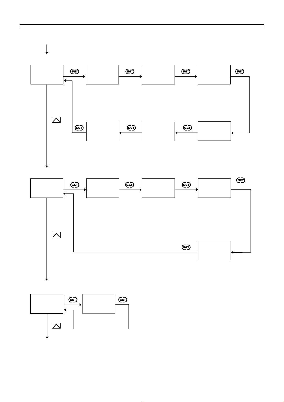
]
]
f
A
f
A
From Parameter setting
mode
Initial setting mode
Initial setting code
1Cod
0000
Initial setting mode
Initial setting code
1Cod
0002
Initial setting mode
Initial setting code
1Cod
0003
To Cod 1021
Twice
Input type
1InP
1100
Set Input type.
1100: RTD input
Pt100
Alarm 2 type
ALM2
0005
Set Alarm 2 type
5: Deviation low
Control output assignment
1oCo
0001
Set Control output
assignment
1: Heat-side output:
Output 1 (OUT1)
Cool-side output:
Output 2 (OUT2)
Display mode selection
dSEL
0001
Set “1: Expanded
display mode”
Decimal point position
PGdP
0001
Set Decimal point
position
1: One decimal place
Alarm 1 type
ALM1
0001
Set Alarm 1 type
1: Deviation high
Output assignment of
Alarm 1
oAL1
0003
Set Output assignment o
larm 1
3: Output 3 (OUT3)
5. OPERATION
Input range high
PGSH
300.0
Set Input range high
300.0
[Setting range:
0.0 to 649.0 C
Input range low
PGSL
000.0
Set Input range low
0.0
[Setting range:
0.0 to 649.0 C
Output assignment of
Alarm 2
oAL2
0003
Set Output assignment o
larm 2
3: Output 3 (OUT3)
Output 3 (OUT3)
energize/de-energize when
assigned to alarm
EXC3
0000
Set Output 3 (OUT3)
energize/de-energize
when assigned to alarm
0: Energize
3 times
IMR02Y03-E1
5-9

5. OPERATION
From Cod 0003
Initial setting mode
Initial setting code
1Cod
1021
Initial setting mode
Initial setting code
1Cod
1041
Initial setting mode
Initial setting code
1Cod
1042
To Cod 1051
Twice
Twice
Temperature unit
UnIT
0001
Set Temperature unit
1: C
Alarm 1 differential gap
dAH1
002.0
Set Alarm 1 differential
gap
2.0
[Setting range:
0.0 to 999.9 C]
Alarm 2 differential gap
dAH2
002.0
Set Alarm 1 differential
gap
2.0
[Setting range:
0.0 to 999.9 C]
Setting limiter high
dSLH
300.0
Set Setting limiter high
300.0
[Setting range:
Setting limiter low to
Input range high]
Alarm 1 action
at input burnout
Abo1
0003
Set Alarm 1 action at input
burnout
3: ON at over-scale or
underscale
Alarm 2 action
at input burnout
Abo2
0003
Set Alarm 2 action at input
burnout
3: ON at over-scale or
underscale
Setting limiter low
dSLL
000.0
Set Setting limiter low
0.0
[Setting range:
Input range low to
Setting limiter high]
Alarm 1 timer
ALT1
0000
Set Alarm 1 timer
0
[Setting range:
0 to 600 seconds]
Alarm 1 interlock
AIL1
0oon
Set Alarm 1 interlock
on: Used
Alarm 2 timer
ALT2
0000
Set Alarm 2 timer
0
[Setting range:
0 to 600 seconds]
Alarm 2 interlock
AIL2
0oon
Set Alarm 2 interlock
on: Used
3 times
5-10
IMR02Y03-E1

d
Initial setting mode
From Cod 1042
Initial setting code
1Cod
1051
Control action
UnXE
0001
Set Control action
1: Heat/Cool PID control
Setting End
Next parameter is displayed.
Set the “Display mode selection” at
display mode.”
Press the key for 2 seconds or more while pressing the
monitor screen.
Control is started (RUN)
Set the highest digit of Set data lock to “0: Lock.”
Set Cool action
Cool action
UOSc
3 times
0000
0: Air cooling
(for Extruder)
Cod 0003 in the Initial setting mode to “0: Standar
Control output at burnout
0obo
0000
Set Control output at
burnout
0: Result of control
computation
key to return to the PV/SV
5. OPERATION
IMR02Y03-E1
5-11

5. OPERATION
5.4 Setting the Control Set Value [Set value (SV)]
After finishing the initial settings, set the control target value, SV.
[Setting example: Set the set value (SV) to 200 C.]
1. Switch the display to the Set value (SV) setting mode
Press the
the SV setting screen from the PV/SV monitor.
key to switch the display to
Monitor display mode
PV/SV monitor
1328
@C 0
Press the
key
SV setting mode
Set value (SV)
1328
0000
2. Shift the highlighted digit to the hundreds digit
Press
the hundreds digit.
The highlighted digit indicates which digit can
be set.
key to shift the highlighted digit to
Highlighted digit
3. Change the numerical value from “0” to “2”
Press the
the numerical value from “0” to “2.”
Setting range:
Setting limiter low to Setting limiter high
Varies with the setting of the Decimal point position.
Factory set value: 0
key twice to change
4. Store the set value (SV)
Press the
The display changes to the next parameter.
The parameter displayed after the set value
(SV) varies depends on the product
specifications.
key to store the set value.
Set value (SV)
1328
0000
Set value (SV)
1328
0000
Set value (SV)
1328
0200
Press the
key twice
Press the
key twice
Press the
key
1328
0000
Shift the highlighted
digit.
1328
0200
Monitor display mode
PV/SV monitor
1328
@200
Set value change and registration
The highlighted digit indicates which digit can be set. The highlighted digit can be shifted by
5-12
pressing the key.
However, the changed data is not stored by the operation of the and keys alone. In order
to store the new parameter value, the key must be pressed within 1 minute after the new value
is displayed. The new value will then be saved and the display will move to the next parameter.
In any mode other than the Initial setting mode, if no registration is made within 1 minute after the
change, the display returns to the PV/SV monitor. In such a case the changed data is not stored.
IMR02Y03-E1

5.5 Setting the Alarm Set Value
After finishing the initial settings, set the alarm set values if they are used.
[Setting example: Set the Alarm 1 set value (ALM1) to 20 C.]
1. Switch the mode to the Parameter setting mode
[Switch the screen to Alarm 1 set value (ALM1)]
Press and hold the
more on the PV/SV monitor screen until
Parameter setting mode is displayed.
The first screen in the Parameter setting mode is
Alarm 1 set value (ALM1).
key for 2 seconds or
Monitor display mode
PV/SV monitor
1328
@C 0
Press and hold
the key
for 2 seconds
or more
5. OPERATION
Parameter setting
mode
Alarm 1 set value
1AL1
0010
2. Shift the highlighted digit to the tens digit
Press the
to the tens digit. The highlighted digit indicates
which digit can be set.
key to shift the highlighted digit
3. Change the numerical value from “1” to “2”
Press the
value from “1” to “2.”
Setting range:
1999 to 9999 or 199.9 to 999.9
(Unit: C [F])
Varies with the setting of the Decimal point position.
Factory set value: 10
key once to change the numerical
4. Store the Alarm 1 set value
Press the
display changes to the next parameter.
key to store the set value. The
Alarm 1 set value
1AL1
0010
Highlighted digit
Alarm 1 set value
1AL1
0010
Alarm 1 set value
1AL1
0020
Press the
key
1AL1
0010
Shift the highlighted
digit.
Press the
key
1AL1
0020
Press the
key
警報 2設定値
1AL2
0010
Set value change and registration
The highlighted digit indicates which digit can be set. The highlighted digit can be shifted by
pressing the key.
However, the changed data is not stored by the operation of the and keys alone. In order
to store the new parameter value, the key must be pressed within 1 minute after the new value
is displayed. The new value will then be saved and the display will move to the next parameter.
In any mode other than the Initial setting mode, if no registration is made within 1 minute after the
change, the display returns to the PV/SV monitor. In such a case the changed data is not stored.
IMR02Y03-E1
5-13

5. OPERATION
A
A
5.6 Tuning the PID Parameters (Execution of AT)
Suitable PID values are automatically calculated by Autotuning (AT) function.
The Autotuning (AT) function automatically measures, computes and sets the optimum PID values.
Before starting the Autotuning, make sure that all required conditions to start the AT are satisfied.
(Refer to 11.3 Setting PID Values Automatically (Autotuning) [P. 11-8])
1. Switch the mode to the Parameter setting mode
Press and hold the
more on the PV/SV monitor screen until
Parameter setting mode is displayed.
The first screen in the Parameter setting mode is
Alarm 1 set value (ALM1).
(If alarm is supplied)
key for 2 seconds or
2. Switch the display to the Autotuning (AT)
Press the
displayed.
The number of available displays depends on
the specification.
key until the Autotuning (AT) is
3. Change the numerical value from “0” to “1”
Press the
value from “0” to “1.”
Setting range: 0: PID control
1: Start Autotuning (AT)
Factory set value: 0
key to change the numerical
Monitor display mode
PV/SV monitor
1328
@C 0
Alarm 1 set value
1AL1
0010
Autotuning (AT)
1ATU
0000
Press and hold
the key
for 2 seconds
or more
Press the
key until the
T screen
Press the
key
Parameter setting
mode
Alarm 1 set value
1AL1
0010
Autotuning (AT)
1ATU
0000
1ATU
0001
4. Start the Autotuning (AT)
Press the
display shows the next parameter and the
autotuning (AT) is started.
The Autotuning (AT) lamp starts flashing.
key to store the set value. The
Autotuning (AT)
1ATU
0001
Press the
key
T lamp (flashing)
Startup tuning (ST)
1STU
0001
OUT3OUT2OUT1AT AL M
5. Finish the Autotuning (AT)
When the Autotuning (AT) is finished, the control will automatically return to “0: PID control” and the
AT lamp turns off.
5-14
IMR02Y03-E1

5. OPERATION
When canceling the Autotuning (AT) function, press the key to be set to “0: PID control”
with the Autotuning (AT) screen.
To return to the PV/SV monitor, press and hold the key for 2 seconds or more.
If no key operation is performed within 1 minute, the display returns to the PV/SV monitor screen.
If the Autotuning (AT) is not completed yet at this moment, the Autotuning (AT) continues even
after the display has returned to the PV/SV monitor.
IMR02Y03-E1
5-15

MEMO
5-16 IMR02Y03-E1

INPUT FUNCTION
This chapter describes input related functions, setting contents and setting
procedure based on the key words related to inputs.
6.1 Changing Input ................................................................................. 6-2
6.2 Correcting Input ............................................................................... 6-7
6.3 Removing Input Noise ...................................................................... 6-8
6.4 Changing Error Handling at Input Error .......................................... 6-10
IMR02Y03-E1 6-1

6. INPUT FUNCTION
6.1 Changing Input
Measured input can be changed at following parameters. Set the input according to the sensor and the
application.
Input type
Decimal point position
Input range high/Input range low
Temperature unit
Description of function
Input range high/low
High and low limits of the input range can be changed within the measured range.
(The input range specified when ordered can be changed by setting the input range high and low.)
Example of input change 1:
Changing thermocouple K “200 to 1372 C” to “0 to 400 C”
Measured range low
200 C
Measured range
Input span
1572 C
Input span
400 C
Input range low
0 C
Input range high
400 C
Example of input change 2:
When a range of
200 to 1372 C with a type K thermocouple input is changed from “No decimal
place” to “One decimal place,” the measured range is changed to 199.9 to 800.0 C. For a
thermocouple input K with a range with one decimal place, the maxi mum measured range is limited
to 199.9 to 800.0 C.
Measured range low
200 C
Measured range without
a decimal place
Input span
1572 C
Measured range low
199.9 C
Measured range with
one decimal place
Input span
999.9 C
Measured range high
+800.0 C
Changing a Decimal point position changes the input resolution.
Measured range high
+1372 C
Measured range high
+1372 C
6-2 IMR02Y03-E1

6. INPUT FUNCTION
Parameter setting
Refer to the Measured range table (P. 6-5) for the measured range of each input type.
For the input range code, refer to Input range code table (P. 6-5).
Input type
[Initial setting mode: Cod 0000]
Parameter symbol Data range Factory set value
xInP
0000: TC input K
0001: TC input J
0010: TC input L
0011: TC input E
0100: TC input N
0101: TC input T
0110: TC input U
0111: TC input R
1000: TC input S
1001: TC input B
1010: TC input W5Re/W26Re
1011: TC input PL II
1100: RTD input Pt100
1101: RTD input JPt100
When input range code is
specified at the time of
ordering, the input type in the
input range code is the factory
setting.
If input range code is not
specified: 0000
Some parameters are initialized when Input type is changed. Refer to appendix A.1 Parameters to
be Initialized/Changed at the time of changing set values (P. A-2).
Decimal point position
[Initial setting mode: Cod 0000]
Parameter symbol Data range Factory set value
PGdP
0: No decimal place
1: One decimal place
Setting below zero (first decimal place) is possible if the selected input type
has a measured range with a decimal place.
When input range code is
specified at the time of
ordering, the decimal point
position in the input range code
is the factory setting.
If input range code is not
specified: 0
Changing a Decimal point position changes the input resolution.
Range of some parameters are limited when a Decimal point position is changed. Refer to appendix
A.1 Parameters to be Initialized/Changed at the time of changing set values (P. A-2).
Input range high
[Initial setting mode: Cod 0000]
Parameter symbol Data range Factory set value
PGSH
(Input range low 1 digit) to Measured range high
Varies with the setting of the Decimal point position.
When the input range is changed, it is recommended to set a value within the specified range
shown in the measured range table. Setting a value outside the described range may change
the input resolution.
When input range code is
specified at the time of
ordering, the input range high
in the input range code is the
factory setting.
If input range code is not
specified: 400
IMR02Y03-E1
Some parameters are limited when Input range high limit or low limit is changed. Refer to
appendix A.1 Parameters to be Initialized/Changed at the time of changing set values (P. A-2).
6-3

6. INPUT FUNCTION
Input range low
[Initial setting mode: Cod 0000]
Parameter symbol Data range Factory set value
PGSL
Measured range low to (Input range high 1 digit)
Varies with the setting of the Decimal point position.
When input range code is
specified at the time of
ordering, the input range low in
the input range code is the
factory setting.
If input range code is not
specified: 0
When the input range is changed, it is recommended to set a value within the specified range
shown in the measured range table. Setting a value outside the described range may change
the input resolution.
Some parameters are limited when Input range high limit or low limit is changed. Refer to
appendix A.1 Parameters to be Initialized/Changed at the time of changing set values (P. A-2).
Temperature unit
[Initial setting mode: Cod 1021]
EX
Parameter symbol Data range Factory set value
UnIT
0: C
1: F
When input range code is
specified at the time of
ordering, the temperature unit
in the input range code is the
factory setting.
If input range code is not
specified: 0
Changing a temperature unit changes the input resolution.
To show the “Temperature unit,” enter the Expanded display mode by setting the “Display mode
selection” at Cod 0003 in the Initial setting mode.
Some parameters are limited when Temperature unit is changed. Refer to appendix A.1
Parameters to be Initialized/Changed at the time of changing set values (P. A-2).
6-4
IMR02Y03-E1
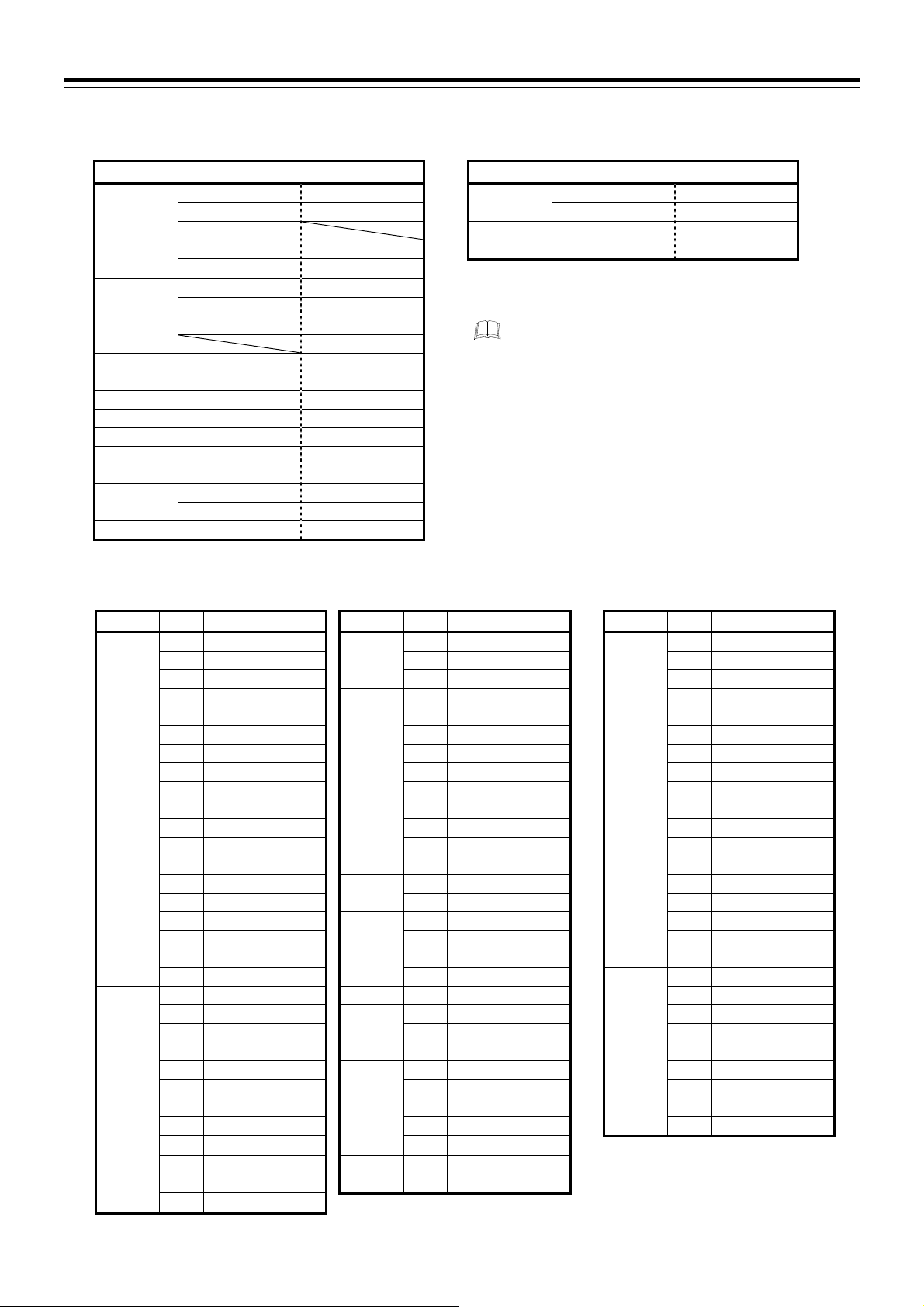
6. INPUT FUNCTION
Measured range table
TC input RTD input
Input type Measured range
200 to 1372 C 328 to 2502 F
K
J
T
S 0 to 1769 C 0 to 3216 F
R 0 to 1769 C 0 to 3216 F
E 0 to 1000 C 0 to 1832 F
B 0 to 1820 C 0 to 3308 F
N 0 to 1300 C 0 to 2372 F
PLⅡ 0 to 1390 C 0 to 2534 F
W5Re/W26Re 0 to 2320 C 0 to 4208 F
U
L 0 to 900 C 0 to 1652 F
199.9 to 400.0 C 100.0 to 752.0 F 199.9 to 649.0 C 199.9 to 999.9 F
199.9 to 800.0 C
200 to 1200 C 328 to 2192 F 199.9 to 649.0 C 199.9 to 999.9 F
199.9 to 300.0 C 199.9 to 550.0 F
200 to 400 C 328 to 752 F
199.9 to 300.0 C 199.9 to 300.0 F
199.9 to 400.0 C 199.9 to 600.0 F
199.9 to 752.0 F
200 to 600 C 328 to 1112 F
199.9 to 600.0 C 199.9 to 999.9 F
Input type Measured range
Pt100
JPt100
200 to 649 C 328 to 1200 F
200 to 649 C 328 to 1200 F
Measured range table and Input range
code table
The measured range table shows the measured
range of each input by the temperature unit and
a decimal point position. Input resolution
depends on the range.
The range code table is a list of input range
codes so that a user can specify the input range
at the time of ordering.
Even if the input range has been specified when
ordered, the input range can be changed later
within the measured range.
Input range code table (Input ranges specifiable at ordering)
TC input RTD input
Input type Code Range Input type Code Range Input type Code Range
K K01 0 to 200 C J JA7 0 to 300 F Pt100 D01 199.9 to 649.0 C
K02 0 to 400 C JB9 328 to 2192 F D02 199.9 to 200.0 C
K03 0 to 600 C JC8 199.9 to 550.0 F D03 100.0 to 50.0 C
K04 0 to 800 C T T01 199.9 to 400.0 C D04 100.0 to 100.0 C
K05 0 to 1000 C T02 199.9 to 100.0 C D05 100.0 to 200.0 C
K06 0 to 1200 C T03 100.0 to 200.0 C D06 0.0 to 50.0 C
K07 0 to 1372 C T04 0.0 to 350.0 C D07 0.0 to 100.0 C
K09 0.0 to 400.0 C T05 199.9 to 300.0 C D08 0.0 to 200.0 C
K10 0.0 to 800.0 C T06 0.0 to 400.0 C D09 0.0 to 300.0 C
K13 0 to 100 C R R01 0 to 1600 C D10 0.0 to 500.0 C
K14 0 to 300 C R02 0 to 1769 C DA1 199.9 to 999.9 F
K17 0 to 450 C R04 0 to 1350 C DA3 199.9 to 200.0 F
K20 0 to 500 C RA1 0 to 3200 F DA4 199.9 to 100.0 F
K41 200 to 1372 C S S01 0 to 1600 C DA5 199.9 to 300.0 F
K43 199.9 to 400.0 C S02 0 to 1769 C DA6 0.0 to 100.0 F
KA1 0 to 800 F B B01 400 to 1800 C DA8 0.0 to 400.0 F
KA2 0 to 1600 F B02 0 to 1820 C DA9 0.0 to 500.0 F
KA3 0 to 2502 F E E01 0 to 800 C DB2 199.9 to 900.0 F
KC8 100.0 to 752.0 F E02 0 to 1000 C JPt100 P01 199.9 to 649.0 C
J J01 0 to 200 C N N01 0 to 1200 C P02 199.9 to 200.0 C
J02 0 to 400 C
J03 0 to 600 C W02 0 to 2320 C P05 100.0 to 200.0 C
J04 0 to 800 C WA1 0 to 4000 F P06 0.0 to 50.0 C
J05 0 to 1000 C PL II A01 0 to 1300 C P07 0.0 to 100.0 C
J06 0 to 1200 C A02 0 to 1390 C P08 0.0 to 200.0 C
J07 199.9 to 300.0 C A03 0 to 1200 C P09 0.0 to 300.0 C
J10 0 to 450 C AA1 0 to 2400 F P10 0.0 to 500.0 C
JA1 0 to 800 F AA2 0 to 2534 F
JA2 0 to 1600 F U U01 199.9 to 600.0 C
JA3 0 to 2192 F L L01 0 to 400 C
JA6 0 to 400 F
W5Re/
W26Re
W01 0 to 2000 C P04 100.0 to 100.0 C
IMR02Y03-E1
6-5

6. INPUT FUNCTION
A
Setting procedure
Input type, Decimal point position and Input range high/low can be set at Cod 0000 in the Initial setting
mode.
Temperature unit can be set at
Procedure to enter the Initial setting mode
Monitor display mode
PV/SV monitor
1328
To change
temperature
unit
@C 0
Initial setting mode
Initial setting code
1Cod
0000
Initial setting mode
Initial setting code
1Cod
0003
Initial setting mode
Initial setting code
1Cod
1021
While pressing the
key, press
the key for
2 seconds or more
3 times
2 seconds
or more
1InP
Set Input type
Display mode selection
Cod 1021 in the Initial setting mode.
Parameter setting mode
Alarm 1 set value
1AL1
0010
nother parameter
may be displayed
depending on the
specification
Input type
Decimal point position
Press the SET
key repeatedly
till
LCK appears
PGdP
0000
dSEL
0001
Set “1: Expanded
display mode”
Temperature unit
UnIT
0001
Set Temperature
unit
0000
Set Decimal point
position
Setting End
Next parameter is displayed.
Press the
Set the highest digit of Set data lock to “0: Lock.”
Setting End
Next parameter is displayed.
Set the “Display mode selection” at
setting mode to “0: Standard display mode.”
Press the
Set the highest digit of Set data lock to “0: Lock.”
Set data lock
1LCK
1000
Set “1”
Initial setting
mode display
Input range high
PGSH
0400
Set Input range high
3 times
key for 2 seconds or more while pressing the
key to return to the PV/SV monitor screen.
key for 2 seconds or more while pressing the
key to return to the PV/SV monitor screen.
To change temperature unit
Temperature unit remains
unchanged
Cod 0003 in the Initial
PGSL
Set Input range low
Input range low
0000
6-6
IMR02Y03-E1
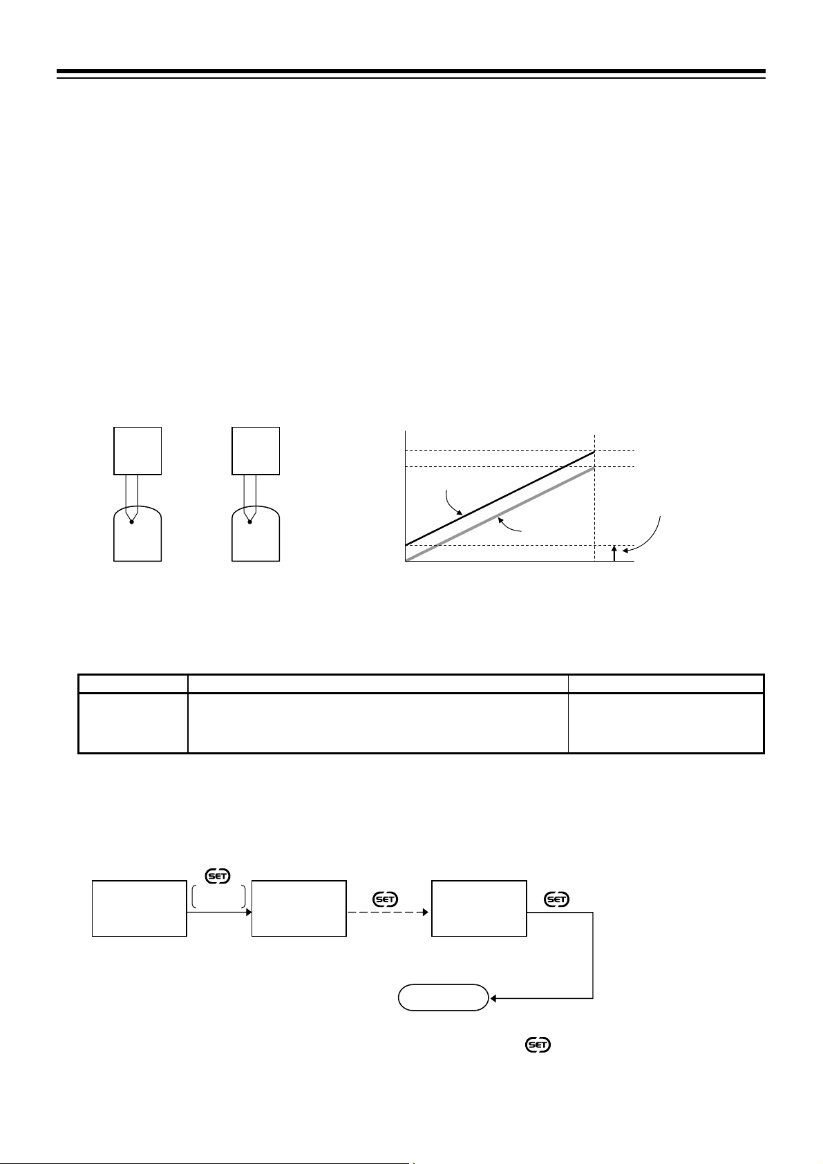
6. INPUT FUNCTION
A
n
6.2 Correcting Input
PV bias can be used for Input correction. The PV bias is used to compensate the individual variations of the
sensors or correct the difference between the Measured value (PV) of other instruments.
Description of function
PV bias
PV bias adds bias to the Measured value (PV).
Setting example of PV bias:
When measuring the same type of load by using different sensors, the Measured value (PV) will be
displayed differently based on the features of sensors:
RZ400 [A]: 200 C RZ400 [B]: 198 C
To correct the Measure value (PV) of RZ400 [B], add bias of 2 C by PV bias:
Displayed value = Measured value (PV) + PV bias 198 C 2 C 200 C
[A]
200 C
RZ400
RZ400
Sensor A Sensor B
Load B Load A
Parameter setting
198 C
[B]
Level (Temperature)
200 C
198 C
PV after adding bias
2 C
0 C
PV bias
2 C
PV change
Time
PV bias
[Parameter setting mode]
Parameter symbol Data range Factory set value
0 or 0.0
ccPB
1999 to 9999 or 199.9 to 999.9
(Unit: C [F])
Varies with the setting of the Decimal point position.
Setting procedure
PV bias can be set in Parameter setting mode.
Monitor display mode
PV/SV monitor
1328
@C 0
2 seconds
or more
Parameter setting mode
Alarm 1 set value
1AL1
0010
nother parameter
may be displayed
depending on the
specification
Press the SET
key repeatedly
Pb appears
till
PV bias
1LPb
0000
Set PV bias
Setting End
Next parameter is displayed.
Press and hold the
to the PV/SV monitor screen.
key for 2 seconds or more to retur
IMR02Y03-E1
6-7
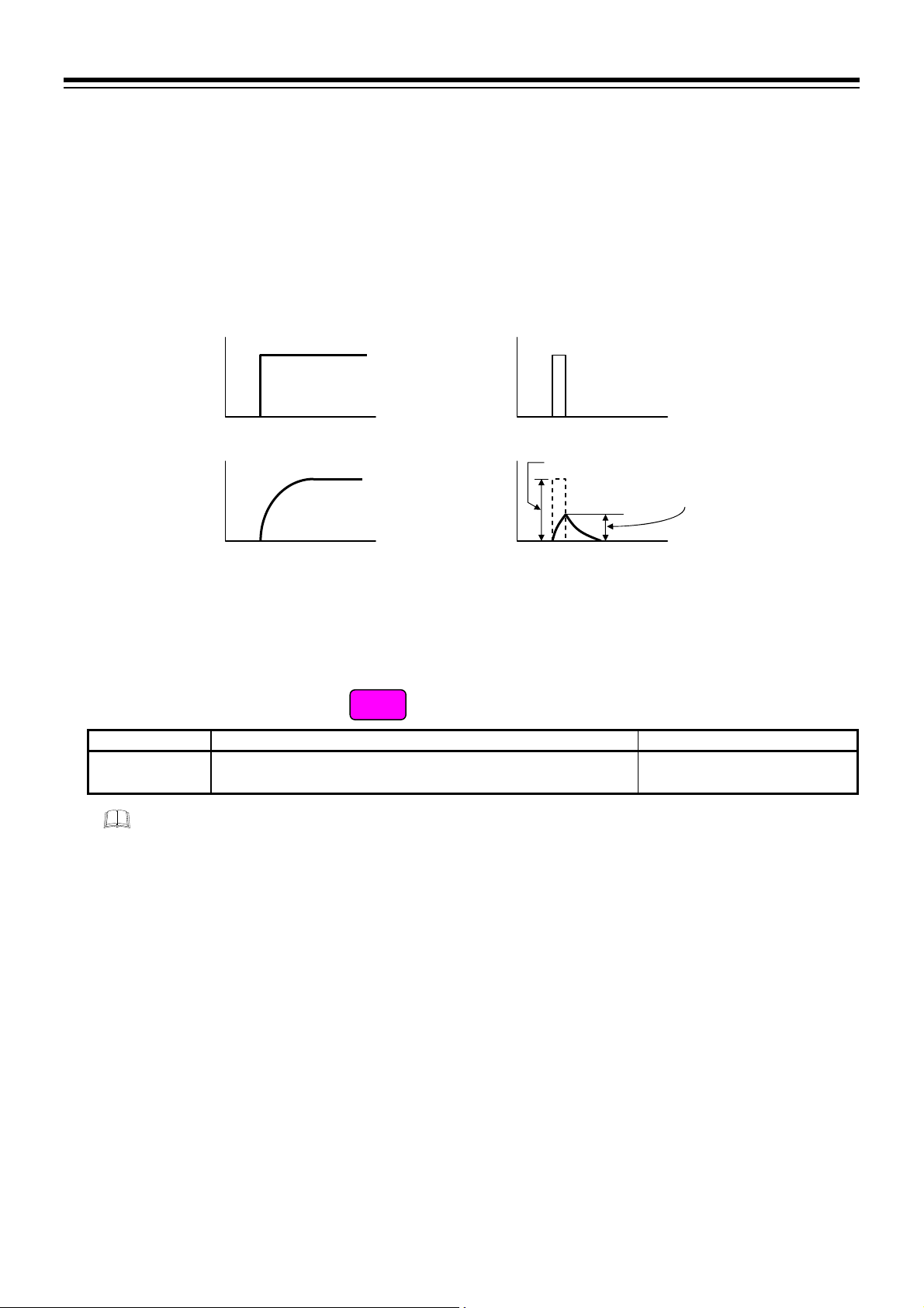
6. INPUT FUNCTION
6.3 Removing Input Noise
To remove input noise influence, first-order delay PV digital filter is available.
Description of function
PV digital filter is software designed to reduce variance of PV caused by noise. Effect of Input noise can be
reduced by setting time constant of PV digital filter based on the controlled object requirement and its level
of noise. Setting a value too small leads to a poor result of PV digital filter; just as an input response will be
poor when setting a value too large.
Parameter setting
Actual PV Pulse input by noise
Input amplitude
Filtered input
amplitude
PV after setting
PV digital filter
PV digital filter
[Parameter setting mode]
Parameter symbol Data range Factory set value
ccdF
To show the “PV digital filter,” enter the Expanded display mode by setting the “Display mode
selection” at Cod 0003 in the Initial setting mode.
0 to 100 seconds
(0: Digital filter function OFF)
EX
1
6-8
IMR02Y03-E1

6. INPUT FUNCTION
A
A
Setting procedure
PV digital filter can be set in the Parameter setting mode.
To show the PV digital filter, enter the Expanded display mode by setting the “Display mode selection” at
Cod 0003 in the Initial setting mode.
Procedure to enter the Initial setting mode
Monitor display mode
PV/SV monitor
1328
@C 0
While pressing the
key, press
the key for
2 seconds or more
Initial setting mode
Initial setting code
1Cod
0000
While pressing the
key, press
the key for
2 seconds or more
Monitor display mode
PV/SV monitor
1328
@C 0
2 seconds
or more
3 times
2 seconds
or more
Parameter setting mode
Alarm 1 set value
1AL1
0010
nother parameter
may be displayed
depending on the
specification
1Cod
0003
Parameter setting mode
Alarm 1 set value
1AL1
0010
nother parameter
may be displayed
depending on the
specification
Press the SET
key repeatedly
till
LCK appears
Display mode selection
Press the SET
key repeatedly
till
dF appears
Setting End
Set data lock
1LCK
1000
Set “1”
Initial setting
mode display
dSEL
0001
Set “1: Expanded
display mode”
PV digital filter
1LdF
0001
Set PV digital filter
Next parameter is displayed.
Set the “Display mode selection” at
setting mode to “0: Standard display mode.”
Press and hold the
the PV/SV monitor screen.
Set the highest digit of Set data lock to “0: Lock.”
key for 2 seconds or more to return to
Cod 0003 in the Initial
IMR02Y03-E1
6-9

6. INPUT FUNCTION
1
4
4
6.4 Changing Error Handling at Input Error
PV flashing display at input error, Control output at burnout and Alarm action at input burnout can be set.
Description of function
When the Measured value (PV) exceeds the input range high limit or goes below the input range low limit,
action is switched to the one specified in the Selection of control output at input burnout. Alarm functions
according to the setting of the Selection of alarm action at input burnout.
Measured value
(PV) display
Manipulated output
(MV)
Alarm at input
burnout
Refer to the Measured range table (P. 6-5) for the measured range of each input type.
Display limit low
Underscale
uuuu [Flashing]
Action area at input error
Output limiter low
(Output OFF)
Chooses
either
Result of control
computation
Alarm ON
1
Minimum display limit is 1999 or 199.9
2
Maximum display limit is 9999 or 999.9
3
“Flashing display” or “Non-flashing display” of PV can be selected for the “PV flashing display at input error.”
4
Selection of “Alarm NOT forced to ON” at input burnout is possible at Selection of Alarm action at input burnout.
Alarm ON
Measured range
low
5 % of
measured
range
Input range low
Measured
value (PV)
[Flashing]
Result of control computation
Manipulated output value (MV) obtained by PID control
3
Display range limit
Measured range
Measured range
Input range high
Input range
(Input span)
Display limit high 2
high
5 % of
measured
range
Measured
value (PV)
[Flashing]
Action area at input error
Over-scale
3
oooo [Flashing]
Output limiter low
(Output OFF)
Chooses
either
Result of control
computation
[Example of display range at the time of abnormal input]
Input type: thermocouple K, Measured range: 200 to 1372 C, Input range: 0 to 400 C
uuuu [Flashing]
Display limit low
Underscale
279 C
Measured range
5 % of
measured
range
Measured
value (PV)
[Flashing]
low
200 C
Input range low
0 C
Display range limit
Measured range
Input range high
Input range
(Input span: 400 C)
Display limit high
1451 C
Measured range
high
1372 C
5 % of
measured
range
400 C
Measured
value (PV)
[Flashing]
Over-scale
oooo [Flashing]
6-10
IMR02Y03-E1

6. INPUT FUNCTION
Parameter setting
PV flashing display at input error
[Initial setting mode: Cod 1021]
Parameter symbol Data range Factory set value
DSOP
To show the “PV flashing display at input error,” enter the Expanded display mode by setting the
“Display mode selection” at Cod 0003 in the Initial setting mode.
0: Flashing display
1: Non-flashing display
EX
0
Alarm 1 and 2 action at input burnout
[Initial setting mode: Cod 1041, Cod 1042]
Parameter symbol Data range Factory set value
AbO1
AbO2
1
“No action” means alarm action is not forced to ON when burnout occurs. For example, if the alarm is ON when burnout occurs, the
alarm remains ON.
2
Regardless of the alarm state, alarms are forced to turn off when overrange (going over-scale or underscale) happens.
To show the “Alarm 1 action at input burnout” and “Alarm 2 action at input burnout,” enter the
Expanded display mode by setting the “Display mode selection” at Cod 0003 in the Initial setting
mode.
0: Alarm output is not forcibly turned ON when the burnout function is
activated.
1: ON at over-scale; no action at underscale
2: ON at underscale; no action at over-scale
3: ON at over-scale or underscale
4: OFF at over-scale or underscale
2
1
1
EX
3
To show the “Alarm 1 action at input burnout,” set a value other than “None” at Cod 0000 (Alarm 1
type) in the Initial setting mode.
To show the “Alarm 2 action at input burnout,” set a value other than “None” at Cod 0000 (Alarm 2
type) in the Initial setting mode.
For alarm output, refer to 7.1 Changing Output Assignment (P. 7-2).
For alarm type, refer to 10.1.2 Changing alarm type (P. 10-8).
Control output at burnout
[Initial setting mode: Cod 1051]
Parameter symbol Data range Factory set value
o oBO
To show the “Control output at burnout,” enter the Expanded display mode by setting the “Display
mode selection” at Cod 0003 in the Initial setting mode.
0: Result of control computation
1: PID control: Output limiter low (output OFF)
Heat/Cool PID control: 5.0 % (output OFF) *
* Both heating and cooling outputs are forced OFF.
EX
PID control:
0
Heat/Cool PID control:
1
IMR02Y03-E1
6-11

6. INPUT FUNCTION
A
Setting procedure
PV flashing display at input error can be set at Cod 1021 in the Initial setting mode.
Alarm 1 output action at input burnout can be set at
Alarm 2 output action at input burnout can be set at
Control output at burnout can be set at
Cod 1051 in the Initial setting mode.
Procedure to enter the Initial setting mode
Monitor display mode
PV/SV monitor
1328
@C 0
2 seconds
or more
While pressing the
key, press
the key for
2 seconds or more
Parameter setting mode
Alarm 1 set value
1AL1
0010
nother parameter
may be displayed
depending on the
specification
Initial setting mode
Initial setting code
1Cod
0000
3 times
1Cod
0003
To set “PV flashing
display at input error”
To set “Control output at burnout”
Initial setting mode
Initial setting code
A
PV flashing display
To set "Alarm 2 action at input burnout"
To set "Alarm 1 action at input burnout"
at input error
1Cod
1021
To continue
setting
4 times
dSoP
0000
Set PV flashing display
at input error
Press a few times
depending on the setting
item
Go to one of following
instructions:
B C D
Setting End
Next parameter is displayed.
Set the “Display mode selection” at
display mode.”
Press the
monitor screen.
Set the highest digit of Set data lock to “0: Lock.”
Twice
key for 2 seconds or more while pressing the
Cod 1041 in the Initial setting mode.
Cod 1042 in the Initial setting mode.
Set data lock
1LCK
Press the SET
key repeatedly
till
LCK appears
Display mode selection
1000
Set “1”
Initial setting
mode display
dSEL
0001
Set “1: Expanded
display mode”
To continue setting
To end setting
Cod 0003 in the Initial setting mode to “0: Standard
6 times
4 times
3 times
key to return to the PV/SV
Continued on the next page.
To
To
To
D
C
B
6-12
IMR02Y03-E1

6. INPUT FUNCTION
n
B
Initial setting mode
Initial setting code
1Cod
1041
To continue
setting
Press or a few
times depending on the
setting item
Go to one of following
instructions:
A C D
Twice
Alarm 1 action
at input burnout
Abo1
0003
Set Alarm 1 action
at input burnout
3 times
To end setting
To continue
setting
C
Initial setting mode
Initial setting code
1Cod
1042
Twice
To continue
setting
D
Press or a few
times depending on the
setting item
Go to one of following
instructions:
A B D
Initial setting mode
Initial setting code
1Cod
1051
6 times
To continue
setting
Press a few times
depending on the setting
item
Go to one of following
instructions:
A B C
Setting End
Next parameter is displayed.
Set the “Display mode selection” at
Press the
Set the highest digit of Set data lock to “0: Lock.”
Alarm 2 action
at input burnout
Abo2
0003
Set Alarm 2 action
at input burnout
Control output
at burnout
0obo
0000
Set Control output
at burnout
Standard display mode.”
key for 2 seconds or more while pressing the
to the PV/SV monitor screen.
To end setting
To continue
3 times
setting
To end setting
To continue
setting
Cod 0003 in the Initial setting mode to “0:
key to retur
IMR02Y03-E1
6-13

MEMO
6-14 IMR02Y03-E1

OUTPUT
FUNCTION
This chapter describes output related functions, setting contents and setting
procedure based on the key words related to outputs.
7.1 Changing Output Assignment .......................................................... 7-2
7.2 Limiting Output ................................................................................. 7-6
7.3 Changing Proportional Cycle Time .................................................. 7-8
7.4 Changing Alarm Output (Energize/De-energize) ............................ 7-12
7.5 Monitoring Manipulated Output Value ............................................ 7-15
IMR02Y03-E1 7-1

7. OUTPUT FUNCTION
7.1 Changing Output Assignment
This instrument has up to three hardware outputs. The following output signals can be assigned to each
output.
Control output
Alarm output
Heater break alarm (HBA) output (optional)
Description of function
Assign outputs [control output, alarm output, heater break alarm (HBA) output] to the output terminals.
When assigning outputs, assign Control output(s) first. Then, assign Alarm output and Heater break alarm
(HBA) output. Refer to the following table for available assignments.
Output terminals
Output 2 (OUT2)
Output 1 (OUT1)
RZ100/RS100
①
②
③
④
⑤
⑥
⑦
⑧
⑨
⑩
⑪
⑫
Output 3 (OUT3)
Output assignment [for PID control]
Control output
No assignment
Output 1 (OUT1) Output 2 (OUT2) or Output 3 (OUT3) *
Output 2 (OUT2) Output 1 (OUT1) or Output 3 (OUT3) *
Alarm 1
output
Any one of Output 1, 2,
and 3 (OUT1, 2, 3) *
Alarm 2
output
Output 2 (OUT2)
Output 1 (OUT1)
Output 3 (OUT3)
Heater break alarm 1
(HBA1) output
Not settable
RZ400/RS400
①
②
③
④
⑤
⑥
⑦
⑧
⑨
⑩
⑪
⑫
Heater break alarm 2
(HBA2) output
* Output assignment can be overlapped. Overlapped outputs are produced as OR output.
Output assignment [for Heat/Cool PID control]
Control output
Heat-side output Cool-side output
No assignment No assignment
Output 1 (OUT1) Output 2 (OUT2) Output 3 (OUT3) *
Output 2 (OUT2) Output 1 (OUT1) Output 3 (OUT3) *
Output 1 (OUT1) Output 3 (OUT3) Output 2 (OUT2) *
Output 2 (OUT2) Output 3 (OUT3) Output 1 (OUT1) *
* Output assignment can be overlapped. Overlapped outputs are produced as OR output.
Alarm 1
output
Any one of Output 1, 2,
and 3 (OUT1, 2, 3) *
Alarm 2
output
Heater break alarm 1
(HBA1) output
Not settable
Heater break alarm 2
(HBA2) output
7-2 IMR02Y03-E1

Specification of relay contact varies with the assigned output (relay type).
Type Output terminal Output type Specification of relay contact output
RZ100
RS100
RZ400
RS400
RZ400
RS400
RZ100
RS100
RZ400
RS400
Output 1 (OUT1)
Output 2 (OUT2)
Output 3 (OUT3)
Output 3 (OUT3)
Output 1 (OUT1)
Output 2 (OUT2)
Output 1 (OUT1)
Output 2 (OUT2)
Output 3 (OUT3)
If Output 1 or 2 (OUT1 or 2) is voltage pulse output or current output, assigning Alarm output or
Heater break alarm (HBA) output will be ignored.
Parameter setting
Control
output
Control
output
Alarm output
(including
Heater break
alarm output)
7. OUTPUT FUNCTION
Contact type: 1a contact
Contact rating (Resistive load): 250 V AC 3 A, 30 V DC 1 A
Electrical life: 100,000 times or more (Rated load)
Mechanical life: 20 million times or more
(Switching: 300 times/min)
Contact type: 1a contact
Contact rating (Resistive load): 250 V AC 3 A, 30 V DC 1 A
Electrical life: 300,000 times or more (Rated load)
Mechanical life: 50 million times or more
(Switching: 180 times/min)
Contact type: 1a contact
Contact rating (Resistive load): 250 V AC 1 A, 30 V DC 0.5 A
Electrical life: 150,000 times or more (Rated load)
Mechanical life: 20 million times or more
(Switching: 300 times/min)
Control output assignment
[Initial setting mode: Cod 0002]
Parameter symbol Data range Factory set value
c oCo
0: No assignment
1: PID control: Output 1 (OUT1)
Heat/Cool PID control: Heat-side output: Output 1 (OUT1)
Cool-side output: Output 2 (OUT2)
2: PID control: Output 2 (OUT2)
Heat/Cool PID control: Heat-side output: Output 2 (OUT2)
Cool-side output: Output 1 (OUT1)
3: Heat-side output: Output 1 (OUT1)
Cool-side output: Output 3 (OUT3)
4: Heat-side output: Output 2 (OUT2)
Cool-side output: Output 3 (OUT3)
Data range for PID control: 0 to 2
When Control output assignment is set to “No assignment,” then Heater break alarm (HBA)
function is disabled.
When Control output assignment is
specified at the time of ordering, the
ordered output assignment is the
factory setting.
If Control output assignment is not
specified, factory setting depends on
the specification (with or without
outputs).
For details, refer to 1.3 Model Code
(P. 1-4).
IMR02Y03-E1
7-3

7. OUTPUT FUNCTION
Output assignment of Alarm 1, 2
[Initial setting mode: Cod 0002]
Parameter symbol Data range Factory set value
OAL1
OAL2
To show the “Output assignment of Alarm 1,” set a value other than “None” at Cod 0000 (Alarm 1
type) in the Initial setting mode.
To show the “Output assignment of Alarm 2,” set a value other than “None” at Cod 0000 (Alarm 2
type) in the Initial setting mode.
0: No assignment
1: Output 1 (OUT1)
2: Output 2 (OUT2)
3: Output 3 (OUT3)
When Alarm output assignment is
specified at the time of ordering, the
ordered output assignment is the
factory setting.
If Alarm output assignment is not
specified, factory setting depends on
the specification (with or without
outputs).
For details, refer to 1.3 Model Code
(P. 1-4).
If Output 1 or 2 (OUT1 or 2) is voltage pulse output or current output, assignment of Alarm output
is ignored.
Refer to the list of Output assignment (P. 7-2) for assignable alarm output.
For alarm type, refer to 10.1.2 Changing alarm type (P. 10-8).
Output assignment of Heater break alarm 1, 2
[Initial setting mode: Cod 0002]
Parameter symbol Data range Factory set value
OHb1
OHb2
To show the “Output assignment of Heater break alarm 1” and “Output assignment of Heater break
alarm 2,” specify “with current transformer (CT),” which is an optional function. You also need to
set a value other than “0.0” for “Heater break alarm 1 (HBA1) set value” and “Heater break alarm
2 (HBA2) set value.”
0: No assignment
1: Output 1 (OUT1)
2: Output 2 (OUT2)
3: Output 3 (OUT3)
OP
When Heater break alarm output
assignment is specified at the time
of ordering, the ordered output
assignment is the factory setting.
If Heater break alarm output
assignment is not specified: 0
7-4
If Output 1 or 2 (OUT1 or 2) is voltage pulse output or current output, assignment of Heater break
alarm (HBA) output is ignored.
Refer to the list of Output assignment (P. 7-2) for assignable Heater break alarm (HBA) output.
IMR02Y03-E1

7. OUTPUT FUNCTION
A
Setting procedure
Control output assignment, Output assignment of Alarm and Output assignment of Heater break alarm can
be set at
Cod 0002 in the Initial setting mode.
Procedure to enter the Initial setting mode
Monitor display mode
PV/SV monitor
1328
@C 0
While pressing the
key, press
the key for
2 seconds or more
Initial setting mode
Initial setting code
2 seconds
or more
Parameter setting mode
Alarm 1 set value
1AL1
0010
nother parameter
may be displayed
depending on the
specification
1Cod
0000
Twice
Initial setting mode
Initial setting code
1Cod
0002
Control output
assignment
1oCo
0001
Set Control output
assignment
Setting End
Next parameter is displayed.
Press the
Set the highest digit of Set data lock to “0: Lock.”
key to return to the PV/SV monitor screen.
Set Output assignment
of Alarm 1
key for 2 seconds or more while pressing the
Press the SET
key repeatedly
till
LCK appears
Output assignment
of Alarm 1
oAL1
0003
Set data lock
1LCK
1000
Set “1”
Initial setting
mode display
Output assignment
of Alarm 2
oAL2
0003
Set Output assignment
of Alarm 2
Output assignment of
Heater break alarm 1
oHb1
0003
Set Output assignment
of Heater break alarm 1
Output assignment of
Heater break alarm 2
oHb2
0003
Set Output assignment
of Heater break alarm 2
IMR02Y03-E1
7-5

7. OUTPUT FUNCTION
7.2 Limiting Output
Use output limiter to limit the output.
Description of function
This is the function which restricts the high and low limits of Manipulated output values (MV).
Output limiter is also effective in ON/OFF control.
Manipulated output value (MV)
105.0 %
Output limiter high
Output limiter low
5.0 %
The manipulated output value
is not produced within this
range.
Manipulated output value (MV)
The manipulated output value is not
produced within this range.
Time
Parameter setting
Output limiter high [Heat-side output limiter (high)]
[Parameter setting mode]
Parameter symbol Data range Factory set value
A oLH
To show the “Output limiter high [Heat-side output limiter (high)],” enter the Expanded display
mode by setting the “Display mode selection” at Cod 0003 in the Initial setting mode.
PID control:
Output limiter low to 105.0 %
(Output limiter high Output limiter low)
Heat/Cool PID control:
0.0 to 105.0 %
EX
105.0
Output limiter low [Cool-side output limiter (high)]
[Parameter setting mode]
Parameter symbol Data range Factory set value
A oLL
To show the “Output limiter low [Cool-side output limiter (high)],” enter the Expanded display
mode by setting the “Display mode selection” at Cod 0003 in the Initial setting mode.
PID control:
5.0 % to Output limiter high
(Output limiter high Output limiter low)
Heat/Cool PID control:
0.0 to 105.0 %
For Heat/Cool PID control, this is a Cool-side output limiter (high).
EX
PID control:
5.0
Heat/Cool PID control:
105.0
7-6
IMR02Y03-E1
 Loading...