

Page 1

GasWatch 2
Operator’s Manual
Part Number: 71-0065RK
Revision: F
Released: 2/2/11
www.rkiinstruments.com
Page 2

WARNING
Read and understand this instruction manual
before operating instrument. Improper use of the
gas monitor could result in bodily harm or death.
Periodic calibration and maintenance of the gas
monitor is essential for proper operation and correct readings. Please calibrate and maintain this
instrument regularly! Frequency of calibration
depends upon the type of use you have and the
sensor types. Typical calibration frequencies for
most applications are between 1 and 3 months,
but can be required more often or less often
based on your usage.
GasWatch 2 Operator’ s Manual
Page 3

Warranty
RKI Instruments, In c. warrants the GasWatch 2 sold by us to be free from
defects in materials, workmanship, and performance for a period of two
years from the date of shipment from RKI Instruments, Inc. This includes
the instrument and the original sensors. Replacement parts are warranted
for 1 year from the date of their shipment from RKI Instruments, Inc. Any
parts found defective within their warranty period will be repaired or
replaced, at our option, free of charge. This warranty does not apply to
those items which by their nature are subject to deterioration or
consumption in normal service, and which must be cleaned, repaired, or
replaced on a routine basis. Examples of such items are:
Absorbent cartridges
Filter elements, disks, or sheets
Pump diaphragms and valves
Warranty is voided by abuse including mechanical damage, alteration,
rough handling, o r r epair procedures not in accordance w i th t he instruction
manual. This warranty indicates the full extent of our liability, and we are
not responsible for removal or replacement costs, local repair costs,
transportation costs, or contingent expenses incurred without our prior
approval.
THIS WARRANTY IS EXPRESSLY IN LIEU OF ANY AND ALL OTHER WARRANTIES
AND REPRESENTATIONS, EXPRESSED OR IMPLIED, AND ALL OTHER OBLIGATIONS
OR LIABILITIES ON THE PART OF RKI INSTRUMENTS, INC. INCLUDING BUT NOT
LIMITED TO THE WARRANTY OF MERCHANTABILITY OR FITNESS FOR A
PARTICULAR PURPOSE. IN NO EVENT SHALL RKI INSTRUMENTS, INC. BE LIABLE
FOR INDIRECT, INCIDENTAL, OR CONSEQUENTIAL LOSS OR DAMAGE OF ANY KIND
CONNECTED WITH THE USE OF ITS PRODUCTS OR FAILURE OF ITS PRODUCTS TO
FUNCTION OR OPERATE PROPERLY.
This warranty covers instruments and parts sold to users only by
authorized distributors, dealers, and representatives as appointed by RKI
Instruments, Inc.
We do not assume indemn ification for any accident or damage caused by
the operation of this gas monitor and our warranty is limited to replacement
of parts or our complete goods.
GasWatch 2 Operator’s Manual Warranty
Page 4

Table of Contents
Introduction . . . . . . . . . . . . . . . . . . . . . . . . . . . . . . . . . . . . . . . . . . . . . . . . . . . . . . . . . .1
Specifications. . . . . . . . . . . . . . . . . . . . . . . . . . . . . . . . . . . . . . . . . . . . . . . . . . . . . . . . . 2
Description. . . . . . . . . . . . . . . . . . . . . . . . . . . . . . . . . . . . . . . . . . . . . . . . . . . . . . . . . . .4
Case . . . . . . . . . . . . . . . . . . . . . . . . . . . . . . . . . . . . . . . . . . . . . . . . . . . . . . . . . . . 5
Wristband . . . . . . . . . . . . . . . . . . . . . . . . . . . . . . . . . . . . . . . . . . . . . . . . . . . . . . . 5
Sensor Cap/.Sensor Cover. . . . . . . . . . . . . . . . . . . . . . . . . . . . . . . . . . . . . . . . . . 5
Charcoal Filter Disk in GW-2C . . . . . . . . . . . . . . . . . . . . . . . . . . . . . . . . . . . . . . . 5
Sensor. . . . . . . . . . . . . . . . . . . . . . . . . . . . . . . . . . . . . . . . . . . . . . . . . . . . . . . . . . 6
LCD. . . . . . . . . . . . . . . . . . . . . . . . . . . . . . . . . . . . . . . . . . . . . . . . . . . . . . . . . . . . 6
Control Buttons. . . . . . . . . . . . . . . . . . . . . . . . . . . . . . . . . . . . . . . . . . . . . . . . . . . 6
Printed Circuit Boards. . . . . . . . . . . . . . . . . . . . . . . . . . . . . . . . . . . . . . . . . . . . . . 7
Alarm Lights . . . . . . . . . . . . . . . . . . . . . . . . . . . . . . . . . . . . . . . . . . . . . . . . . . . . . 8
Buzzer. . . . . . . . . . . . . . . . . . . . . . . . . . . . . . . . . . . . . . . . . . . . . . . . . . . . . . . . . . 8
Vibrator . . . . . . . . . . . . . . . . . . . . . . . . . . . . . . . . . . . . . . . . . . . . . . . . . . . . . . . . . 8
Lithium Battery . . . . . . . . . . . . . . . . . . . . . . . . . . . . . . . . . . . . . . . . . . . . . . . . . . . 8
Start Up. . . . . . . . . . . . . . . . . . . . . . . . . . . . . . . . . . . . . . . . . . . . . . . . . . . . . . . . . . . . . . 9
Start-up Procedure . . . . . . . . . . . . . . . . . . . . . . . . . . . . . . . . . . . . . . . . . . . . . . . . 9
Performing a Fresh Air Adjustment. . . . . . . . . . . . . . . . . . . . . . . . . . . . . . . . . . . . 9
Turning Off the GasWatch 2 . . . . . . . . . . . . . . . . . . . . . . . . . . . . . . . . . . . . . . . . 10
Operation . . . . . . . . . . . . . . . . . . . . . . . . . . . . . . . . . . . . . . . . . . . . . . . . . . . . . . . . . . . 11
Measuring Mode. . . . . . . . . . . . . . . . . . . . . . . . . . . . . . . . . . . . . . . . . . . . . . . . . 11
Displaying the Peak, STEL, & TWA (GW-2C & GW-2H) . . . . . . . . . . . . . . . . . . 11
Displaying Min and Max (GW-2X). . . . . . . . . . . . . . . . . . . . . . . . . . . . . . . . . . . . 12
Alarms. . . . . . . . . . . . . . . . . . . . . . . . . . . . . . . . . . . . . . . . . . . . . . . . . . . . . . . . . 13
Displaying and Setting the Alarm Points. . . . . . . . . . . . . . . . . . . . . . . . . . . . . . . . . . 17
Setting the Time. . . . . . . . . . . . . . . . . . . . . . . . . . . . . . . . . . . . . . . . . . . . . . . . . . . . . . 20
Calibration . . . . . . . . . . . . . . . . . . . . . . . . . . . . . . . . . . . . . . . . . . . . . . . . . . . . . . . . . . 21
Setting the Fresh Air Reading. . . . . . . . . . . . . . . . . . . . . . . . . . . . . . . . . . . . . . . 21
Setting the Span (Zero for GW-2X). . . . . . . . . . . . . . . . . . . . . . . . . . . . . . . . . . . 21
Table of Contents GasWatch 2 Operator’ s Manual
Page 5

Maintenance. . . . . . . . . . . . . . . . . . . . . . . . . . . . . . . . . . . . . . . . . . . . . . . . . . . . . . . . . 24
Troubleshooting . . . . . . . . . . . . . . . . . . . . . . . . . . . . . . . . . . . . . . . . . . . . . . . . . 24
Replacing the Lithium Battery. . . . . . . . . . . . . . . . . . . . . . . . . . . . . . . . . . . . . . . 25
Replacing the Sensor . . . . . . . . . . . . . . . . . . . . . . . . . . . . . . . . . . . . . . . . . . . . . 27
Replacing the Sensor Cover. . . . . . . . . . . . . . . . . . . . . . . . . . . . . . . . . . . . . . . . 28
Replacing the Charcoal Filter Disk . . . . . . . . . . . . . . . . . . . . . . . . . . . . . . . . . . . 29
Replacing the Wristband. . . . . . . . . . . . . . . . . . . . . . . . . . . . . . . . . . . . . . . . . . . 29
Parts List. . . . . . . . . . . . . . . . . . . . . . . . . . . . . . . . . . . . . . . . . . . . . . . . . . . . . . . . . . . .31
Appendix A: MRI Applications . . . . . . . . . . . . . . . . . . . . . . . . . . . . . . . . . . . . . . . . . . 32
WARNING: Understand manual before operating. Substitution of
components may impair intrinsic safety. To prevent
ignition of a hazardous atmosphere, batteries must only
be changed in an area known to be nonhazardous. Not
tested in oxygen en riched atmospheres (abo ve 21%).
GasWatch 2 Operator’s Manual Table of Contents
Page 6

Introduction
Using an advanced microprocessor controlled detection system, the
GasWatch 2 Personal Single-Gas Monitor detects the presence of either
carbon monoxide (CO), hydrogen sulfide (H2S), or oxygen (O2). The
GasWatch 2’ s comp act size and easy-to-use design make s it ideally suited
for a wide range of applications, including sewage treatment plants,
tunnels, hazardous waste sites, petrochemical facilities, oil fields, mines,
and chemical plants. The GasWatch 2 is even small enough to be worn
comfortably o n the wris t like a watch. The GasWatch 2 offers a full rang e of
features, including:
• Hands free gas monitori n g
• Compact “watch type” design
• Fast, accurate response with digital liquid crystal display (LCD)
• Visual, audible, and vibration alarms
• Microprocessor control for reliability, ease of use, and advanced
capabilities
• Peak, STEL, and TWA indication for GW-2C & GW-2H
• Minimum and maximum indication for GW-2X
• STEL, TW A, an d ov er ran ge al ar m s
• Sensor fail alarm
• Displays current time
• Over 3,000 hours of operation from 1 battery
• CSA classified for Class I, Division I, Groups A, B, C, and D hazardous
atmospheres
WARNING: The GasWatch 2 detects carbon monoxide, hydroge n
sulfide, or oxygen deficiency and elevated levels of
oxygen, all of which can be dangerous or life threatening.
When using the GasWatch 2, you must follow the
instructions and warnings in this manual to assure
proper and safe operation of the unit and to minimize the
risk of personal injury. Be sure to maintain and calibrate
the GasWatch 2 as described in this manual.
1 • Introduction GasWatch 2 Operator’s Manual
Page 7
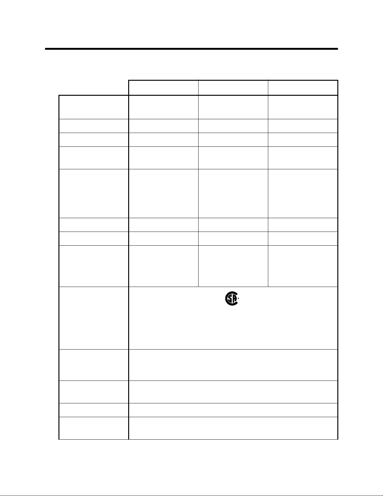
Specifications
Table 1: GasWatch 2 Specifications
GW-2C GW-2H GW-2X
Target Gas Carbon Monoxide
(CO)
Hydrogen Sulfide
(H2S)
Oxygen
(O2)
Detection Range 0 to 500 ppm 0 to 100.0 ppm 0 to 40.0% vol.
Display Increment 1 ppm 0.5 ppm 0.1% vol.
Detection
Electro Chemic al Electro Chemic al Galvanic Cell
Principle
Alarm Points Low 25 ppm
High 50 ppm
TWA 25 ppm
STEL 200 ppm
Low 10.0 ppm
High 30.0 ppm
TWA 10.0 ppm
STEL 15.0 ppm
Low 19.5% vol.
(decreasing)
High 23.5% vol.
(increasing)
Sampling Method Diffusion Diffusion Diffusion
Response Time T90 in 30 seconds T90 in 30 seconds T90 in 20 seconds
Accuracy ± 5% of reading or
± 5 ppm CO
(whichever is
greater)
± 5% of reading or
± 2 ppm H2S
(whichever is
greater)
± 0.5% O
2
Safety/Regulatory
C US
186718
CSA classified, “C/US”, as Intrinsically Safe. Exia. Class I,
Groups A, B, C, & D. Class I, Zone 0, Group IIC.
Temperature Code T4.
Power Tw o AAA size Alka line Batte ries Standard, Duracell M N2400
or PC2400, Eveready Energizer E92 or EN92
Continuous
Approximately 3,000 Hours With No alarms or Backlighing
Operating Hours
Case High-impact Plastic, Dust Proof and Weather Resistant
Standard
Wristband
Accessory
GasWatch 2 Operator’s Manual Specifications • 2
Page 8

Table 1: GasWatch 2 Specifications
GW-2C GW-2H GW-2X
Optional
Accessories
Dimensions and
Weight
Operating T emp. &
Humidity
• Belt Clip
• Hard Hat Clip
• Lapel Clip
Dimensions: 2.5 (H), 1.7 (W), 0.9 (D) inches
Weight: 2 oz.
-10°C - 40°C, below 85% RH (non condensing)
3 • Specifications GasWatch 2 Operator’ s Manual
Page 9
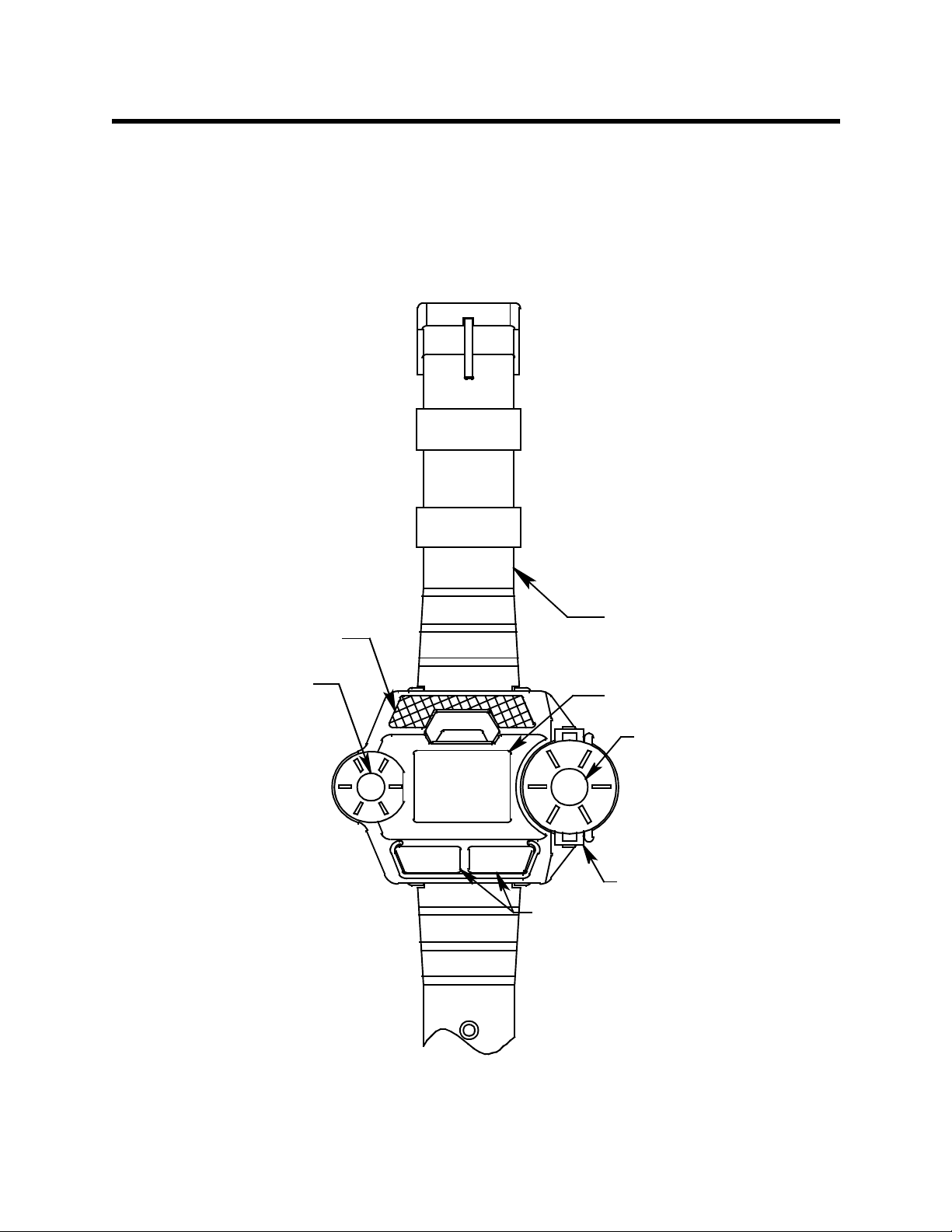
Description
This section describes the components of the GasWatch 2. These
components include the GasWatch 2’s case, wristband, sensor cap and
sensor cover, charcoal filter disk (in the GW-2C), sensor, LCD, control
buttons, printed circuit boards, alarm lights, buzzer, vibrator, and lithium
battery.
Alarm LED Lens
Buzzer Opening
POWER
MODE
Wristband
LCD Display Window
Sensor Diffusion
Port
AIR
Sensor Cap
Control Buttons
Figure 1:Components of the GasWatch 2
GasWatch 2 Operator’s Manual Description • 4
Page 10

Case
The GasWatch 2’s sturdy, high -im pact plastic case is suitable for use in
many environmen ta l condit ions, in doors and out. The uni t is dust pr oof and
weather resistant. The case has two halves, the top case and the bottom
case. They are held together by four screws in the bottom case. The case
is a different color depe nding on the model. The GW-2C for CO is red, the
GW-2H for H2S is orange, and the GW-2 X for oxyg en is bl ue .
The digital LCD is visible through the top case. It displays gas
concentrations, battery level, time, and other readings including TWA,
STEL, and peak gas levels. Below the LCD are two black control buttons.
The button on th e left is labeled POWER/MODE. The b utto n on the right is
labeled AIR.
To the left of the LCD is the buzzer, which is located inside the unit. To the
right of the LCD is the sensor cap which retains the sensor. Above the LCD
is a frosted lens through which the alarm lights are visible.
A battery cover is located on the bottom case and is held in place by two
screws. The wristband attaches to the bottom case.
Wristband
The GasWatch 2 comes with a wristband as a standard accessory so the
unit may be worn as a watch and allow hands-free gas monitoring. The
wristband is held in place with the sam e type of spring ba rs that are used i n
a watch. The spring bars are protected by hollow tubes which fit into the
wristband. Optional accessories are available from RKI Instruments, Inc.
that can be used in place of the wristband such as a belt clip.
Sensor Cap/Sensor Cover
The sensor cap snaps onto the right side of the case and retains the
sensor. It also retains the sensor cover which is a round hydrophobic disk
membrane which protects the sensor from dirt and weather. A gasket
installed on the sensor seals against the sensor, sensor cover, and sensor
cap.
Charcoal Filter Disk in GW-2C
The GW-2C includes a charcoal filter disk which is located in a recessed
area of the sensor gasket be neath the sensor cove r . The charcoal fil ter disk
removes gases from the sampled air that will cause a response on the CO
sensor such as H2S and certain hydrocarbons. If false or elevated CO
readings are noticed, especial l y in the presence of H2S, change the
charcoal filte r disk (see the Maintenance section for instructions).
5 • Description GasWatch 2 Operator’s Manual
Page 11

Sensor
The GasWatch 2 uses either an oxygen, CO, or H2S sensor . The sensor is
protected by the white sensor cover which is held in place by the sensor
cap and sensor gasket. The sensor cover allows ambient air to diffuse past
it to the sensor. The three sensors used in the three GasWatch 2 models
use different detection principles as described below.
Oxygen Sensor
The oxygen sensor is a galvanic type of sensor. A membrane covers the
cell and allows gas to diffuse i nto the cell at a rate proportion al to the par tial
pressure of oxygen. The oxygen react s in the cell and prod uce s a volta ge
proportion al to the concentration of oxygen. The voltage is measured by
the GasWatch 2’s circuitry, converted to a measurement of gas
concentration, and displayed on the LCD.
CO and H2S Sensors
The CO and H
precious metal electrodes in an acid electrolyte. A gas permeable
membrane covers the sensor face and allows gas to diffuse into the
electrolyte. The gas reacts in the sensor and produces a c urrent
proportional to the concentration of the target gas. The current is amplified
by the GasWatch 2’s circuitry, converted to a measurement of gas
concentration, and displayed on the LCD.
S sensors are electrochemical sensors that consist of two
2
LCD
The LCD is visible through the top case. Target gas concentrations, the
time, battery condition, and alarm indications are displayed on the LCD.
When either of the control buttons is pressed, the LCD backlight comes on
for 20 seconds.
Control Buttons
Below the LCD are the two control buttons. They are POWER/MODE and
AIR. They turn on the power to the GasWatch 2 and turn it off. They control
what is displayed on the LCD, including ti me, gas concentrations, peak,
TWA, and S TEL re adin gs, as well as othe r messag es. They a lso allow yo u
to perform a fresh air adjustment, change alarm points, change the time,
and calibrate the instrument. The functions performed by the control
buttons are summarized in the following table:
GasWatch 2 Operator’s Manual Description • 6
Page 12

Table 2: The Control Buttons of the GasWatch 2
Button Function
• Turns the unit on and off.
• Turns the LCD back light on.
• Displays STEL and TWA readings (GW-2H & GW2C).
• Displays peak readings (high for GW-2H & GW-2C
POWER/MODE
and low & high for GW-2X).
• Resets the alarm circuit (gas alarms).
• Enters Calibration Mode with the AIR button.
• Enters Alarm Adjustment Mode with the AIR
button.
• Enters Time Adjustment Mode with the AIR button.
• Turns the LCD back light on.
• Adjusts LCD r eadings w hen a fresh air adju stment
is performed.
• Enters Calibration Mode with the POWER/MODE
button.
AIR
• Enters Alarm Adjustment Mode with the POWER/
MODE button.
• Enters Time Adjustment Mode with the POWER/
MODE button.
• Increases settings when the unit is in Alarm
Adjustment Mode, Time Adjustment Mode, or
Calibration Mode.
Printed Circuit Boards
The primary function of the GasWatch 2’s two printed circuit boards are to
amplify the current or voltage signal sent to them from the gas sensor,
convert the signal to a meaningful measurement of gas concentration,
display the gas concentration on the LCD, store peak, STEL, and TWA
readings, and activate th e alarm cir cuit if an ala rm point h as been reac hed.
They monitor battery level, battery failure, and sensor failure. They also
control the GasW atch 2’ s time funct ion and the vari ous operati ng modes of
the unit.
NOTE: The printed circuit boards co ntain no user serviceab l e parts.
7 • Description GasWatch 2 Operator’s Manual
Page 13

Alarm Lights
The GasWatch 2 has two alarm lights located above the LCD. The alarm
lights are two red LEDs that al ert you to gas, low battery, and sensor failure
alarms. They are visible through a frosted lens.
Buzzer
A solid-state electronic buzzer is mounted inside the GasWatch 2. An
opening on the left side of the top case allows the buzzer’s sound to
resonate from the case. The buzzer sounds for gas alarms, unit
malfunctions, low batter y volt age, and as an indi cator du ring nor mal use of
the various display options of the GasWatch 2.
Vibrator
A vibrating motor ( vibrator) is m ounted in side the GasW atch 2. The vibrator
vibrates momentarily during the power-up sequence and for gas alarms.
Lithium Battery
A 3.0 volt coin type lithium battery powers the GasWatch 2. The battery will
run the unit for approximately 3,000 hours when no alarms have been
activated during that time period. The battery icon on the LCD shows the
charge remaining in the battery. When the GasWatch 2 detects a low
battery voltage, a low battery warning is activated. When the GasWatch 2
determines that the battery is too low for normal operation, a dead battery
alarm is activated. The battery can be replaced by removing the battery
door in the bottom case. See the maintenance section of this manual for
instructions about replacing the battery.
GasWatch 2 Operator’s Manual Description • 8
Page 14

Start Up
This section explains how to start up the GasWatch 2 and to get it ready for
operation.
Start-up Procedure
1. Press and hold the POWER/MODE button for one second to turn on the
GasWatch 2 . The the bu zzer sounds br iefly, the vibrator vibrate s briefly,
all elements of display are activated, and the alarm lights and LCD
backlight turn on for a few seconds.
2. The GasWatch 2 then displays the target gas and time before
displaying the battery voltage. The buzzer sounds again after the
battery voltage is displayed.
CAUTION: If the unit is in low battery warning, change the battery
immediately. If the unit is in dead battery alarm, change the
battery before attempting to use the unit.
3. The gas sensor inside the GasWatch 2 begins operating and the
concentration of the t arget ga s is displayed on the LCD. The GasW a tch
2 is now in Measuring Mode. The target gas is displa yed in the
appropriate units (see specifications) and the current time is displayed
at the bottom of the LCD.
NOTE: Wh en using the GasWatch 2 for the first time, check the current
time and verify that it is correct for your time zone. If it is not, set
the time as described in “Setting the Time”.
Performing a Fresh Air Adjustment
Before using the GasWatch 2, it is a recommended to set the fresh air
reading for the target gas to ensure accurate gas readings in the
monitoring environment.
1. Find a fresh air environment. This is an environment free of toxic or
combustible gases and of normal oxygen content (20.9%).
2. With the unit on and in Measuring Mode, pr ess and h old the AIR butto n
for about three seconds to allow the GasWatch 2 to set the fresh air
reading.
While you are pressing the AIR button, the LCD displays “hold”, a
prompt for you to keep pressing the AIR button.
9 • Start Up GasWatch 2 Operator’ s Manual
Page 15

3. When the fresh air readings have be en set, the L CD displ ays “Adj” f or 2
seconds which prompts you to release the AIR button . The unit will set
the reading to 0 ppm for the GW-2C and GW-2H and to 20.9% oxygen
for the GW-2X.
4. The unit then returns to normal operation and the display indicates the
current gas concentration.
Turning Off the GasWatch 2
1. Press and hold the POWER/MODE button for about five seconds to
turn off the unit. The buzzer will pulse wh ile the POWER/MODE button
is being pressed before the unit turns off.
2. Release the button when the LCD is blank. The unit is off.
GasWatch 2 Operator’s Manual Start Up • 10
Page 16

Operation
This section describes the normal operation of the GasWatch 2. It explains
how the unit can be used to displa y peak, STEL, a nd TWA readings for the
GW-2C and GW-2C, and minimum and maximum readings for the GW-2X.
It also covers alarm indications.
Measuring Mode
After you have powered up the GasWatch 2 and performed a fresh air
adjustment follo wing the instr uctions of the previ ous section, “Start Up”, the
GasWatch 2 is in Measuring Mode.
In Measuring Mode, the battery level, time, and target gas concentration
are displaye d on the LCD. The battery icon has four bars visible when the
battery is full. As the battery charge dec re ases, the ba rs will di sappe ar. On
the GW-2C, CO is displayed in parts per million (ppm). On the GW-2H, H2S
is displayed in ppm. On the GW-2X, oxygen is displaye d as volume percent
(%).
Battery
level
Gas concentration
0
Time
Figure 2: LCD in Measuring Mode
NOTE: The time is displayed in military format with the hour going from 0
to 24.
21:19
Displaying the Peak, STEL, and TWA (GW-2C & GW-2H)
You can display the Peak, STEL, and TWA readings on the GW-2C and
GW-2H when the GasWatch 2 is in Measuring Mode using the POWER/
MODE button. STEL is an acronym for short-term exposure limit, and it is
the average reading of the target gas (H2S or CO) during the last 15
minutes. TW A is an acr on ym for time- wei g hte d aver ag e, and it is the
average reading for the target gas (H2S or CO) during the last eight (8)
hours. If eight (8) hours has not elapsed since the unit was turned on, the
TWA is still calculated over eight hours, with the missing time assigned a
zero (0) value for the readings. Similarly, if the unit has not been on for 15
minutes, the missing time is assigned a 0 val ue and the STEL is calculated
over 15 minutes. The Peak, STEL, and TWA readings are cleared when
the unit is turned off.
ppm
11 • Operation GasWatch 2 Operator’s Manual
Page 17

1. Make sure the GasWatch 2 is in Measuring Mode. The current gas
concentration should be displayed on the LCD.
2. Press and release the POWER/MODE button to enter Peak Display
Mode. This will activate the LCD backlight and display the Peak
reading. A small Peak symbo l is displayed in the up per lef t corner of the
LCD.
3. Press and release the POWER/MODE button again to enter STEL
Display Mode. This will display the STEL reading. The word “STEL” is
displayed in the middle of the LCD above the reading.
4. Press and release the POWER/MODE button again to enter TWA
Display Mode. This will display the TWA reading. The word “TWA” is
displayed in the middle of the LCD above the reading.
5. Press and release the POWER/MODE button once again to return to
Measuring Mode.
NOTE: If you do not press a button for 20 seconds while displaying the
Peak, STEL, or TWA readings, the unit will return to Measuring
Mode automatically and the backlight wil l turn off.
Displaying the Min and Max (GW-2X)
You can display the minimum (Min) and maximum (Max) readings on the
GW-2X when the GasWatch 2 is in Measuring Mode using the POWER/
MODE button. The Min and Max readings are cleared when the unit is
turned off.
1. Make sure the GasWatch 2 is in M easuring Mode. The oxygen
concentration should be displayed on the LCD.
2. Press and release the POWER/MODE button to enter Min Display
Mode. This will activate the LC D backli gh t an d displ a y the M in re ading.
A small Min symbol is displayed in the upper left corner of the LCD.
3. Press and release the POWER/MODE button again to enter Max
Display Mode. This will display the Max reading. A small Max symbol is
displayed in the upper left corner of the LCD.
4. Press and release the POWER/MODE button once again to return to
Measuring Mode.
NOTE: If you do not press a button for 20 seconds while displaying the
Min or Max readings, the unit will return to Me asuring Mode
automatically and the backlight wi ll turn off.
GasWatch 2 Operator’s Manual Operation • 12
Page 18

Alarms
This section covers alarm indications. It also tells you how to reset the
GasWatch 2 after an alarm has occurred and how to respond to an alarm
condition.
Alarm Indications, GW-2C & GW-2H
The GW-2C and the GW-2H will sound an alarm and the unit will vibrate
when the target gas concentration, CO or H2S, rises above the low alarm
point. The GasWatch 2 als o sounds an alarm and v i brates when the high
alarm point, the STEL alarm point, or the TWA alarm point is reached. It
also has a low batter y warni ng, a de ad batt ery al arm, an over rang e ala rm,
a sensor failure alarm, and a syst em fa ilure a lar m. Se e Ta ble 3 b elo w for a
description of each alarm indication.
Alarm Indications, GW-2X
The GW-2X will sound an alarm and the unit will vibra te when the oxygen
concentration fall s be lo w the l ow al ar m point or rises above the hi gh al ar m
point. It also has a low battery warning, a dead battery alarm, an over
range alarm, a sensor failure alarm, and a system failure alarm. See
Table 3 below for a description of each alarm indication.
The table below summarizes the types of ala r ms produced by the
GasWatch 2.
Table 3: Alarm Types and Indications
Alarm T ype LCD Indications Other Indications
Low Alarm
Concentration of gas
rises above the low
alarm point, or for the
GW-2X, falls below
the low alarm point.
High Alarm
Concentration of gas
rises above the high
alarm point.
• Gas reading
flashes.
• Back light turns on.
• Gas reading
flashes.
• Back light turns on.
• Pulsing tone once
per second.
• Unit vibrates once
per second.
• Alarm lights flash
once per second.
• Pulsing tone twice
per second.
• Unit vibrates twice
per second.
• Alarm light flashes
twice per second.
13 • Operation GasWatch 2 Operator’s Manual
Page 19

Table 3: Alarm Types and Indications
Alarm T ype LCD Indications Other Indications
TWA or STEL
(GW-2C & GW-2H
Only)
Concentration of CO
or H2S rises above the
• Back light turns on.
• TWA or STEL
blinks to the left of
the battery icon.
• If the unit is in both
TWA alarm and
TWA or STEL alarm
point.
STEL alarm, both
TWA an d STEL will
be displayed.
Over Range • Gas reading
replaced by blinking
brackets.
• Back light turns on.
Low Battery Warning • Last remaining bar
on the right in
battery icon
flashes.
• Pulsing tone once
per second.
• Unit vibrates once
per second.
• Alarm light flashes
once per second.
• Pulsing tone once
per second.
• Unit vibrates once
per second.
• Alarm light flashes.
•None
Dead Battery Alarm • Gas reading
replaced by FAIL.
• Battery icon
flashes.
Sensor Failure • Gas reading
replaced by FAIL.
System Failure • Gas reading
replaced by FAIL.
• Time replaced by
SYS below FAIL.
• Double Pulsing
Tone (two pulse s i n
quick succession)
once a second.
• Double Pulsing
Tone (two pulse s i n
quick succession)
once a second.
• Double Pulsing
Tone (two pulse s i n
quick succession)
once a second.
GasWatch 2 Operator’s Manual Operation • 14
Page 20

Resetting Gas Alarms
To reset a gas alarm, press the POWER/MODE button after the gas
reading falls below the low alarm point (or above for the GW-2X). If a TWA
or STEL alarm has been activated, i t c annot be reset unless you turn off
the unit.
NOTE: Even though the gas concentration may have ret urned to normal
or may have fallen below the alarm point, the alarm indications will
continue until you have reset the alarm using the MODE/POWER
button.
Responding to Alarms
This section describes response to gas, over range, battery, sensor failure,
and system failure alarms.
Responding to Gas Alarms
1. Follow your estab lished procedure for an increasing gas condition or a
decreasing oxygen condition.
2. Reset the alarm using the POWER/MODE button once the alarm
condition has been cleared.
Responding to an Over Range Alarm
WARNING: An over range condition may indicate an extreme toxic
gas or oxygen concentration. Confirm the gas
concentration with a different GasWatch 2 or with another
gas detecting device.
1. Follow your estab lished procedure for an increasing gas condition.
2. Reset the alarm using the MODE/POWER button once the alarm
condition has cleared.
3. Calibrate the GasWatch 2 as described in the calibration section of this
manual.
4. If the over range condition contin ues, you may need to replace the
sensor.
5. If the over range condition continues after you have replaced the
sensor, contact RKI Instruments, Inc. for further instructions.
15 • Operation GasWatch 2 Operator’s Manual
Page 21

Responding to Battery Alarms
WARNING: The GasWatch 2 is not operational as a gas monitoring
device during a dead battery alarm. Take the GasWatch 2
to a non-hazardous area and change the battery as
described in “Changing the Lithium Battery”.
The GasWatch 2 is fully functional in a low battery warning condition.
However, only a couple of days of operation may remain depending on
certain condi tion s such as a l arm occurrences. Change the battery as soo n
as possible when a low battery warning occurs as described in “Changing
the Lithium Battery”.
NOTE: Alarms and the back light feature consume battery power and
reduce the amount of operating time remaining.
Responding to a Sensor Failure Alarm
1. Try calibrating the sensor first, as described in “Calibration”, before
replacing it.
2. If the sensor failure continues, replace the sensor as described in
“Replacing a Sensor”.
3. If the sensor failure condition continues after you have replaced the
sensor, contact RKI Instruments, Inc. for further instructions.
Responding to a System Failure Alarm
1. If a system failure occurs, try turning off the unit an d turning it on again.
2. If the unit is still in system failure, contact RKI Instruments, Inc. for
further instructions.
GasWatch 2 Operator’s Manual Operation • 16
Page 22

Displaying and Setting the Alarm
Points
The GasWatch 2 allows you to display and set the alarm poi nts. There is a
Low Alarm point and a High alarm point on all three models. The GW-2C
and GW-2H also have ST EL and TWA alarm points. The alarm points and
their factory settings for the three GasWatch 2 models are summarized in
the table below:
Table 4: Alarm Points of the Four Target Gasses
Model Low Alarm High Alarm STEL TWA
GW-2C (CO) 25 ppm 50 ppm 200 ppm 25 ppm
GW-2H (H
GW-2X (O2) 19.5%
In the table above, Lo w Alarm and High Alarm for the GW-2C and GW-2H
refer to a rising concentration of the target ga ses. The Low Alarm is
triggered at the Low Al arm concen tration list ed in the t able. For the GW -2C
that would be 25 ppm CO, a nd for t he GW -2H that woul d be 10.0 ppm. The
High Alarm is triggered when the High Alarm co ncentration is reache d.
For the GW-2X, Low Alarm is triggered when the concentration of oxygen
falls below 19.5%. When the concentration of oxygen rises above 23.5%,
High Alarm is activated.
S) 10.0 ppm 30.0 ppm 15.0 ppm 10.0 ppm
2
Decreasing
23.5%
Increasing
N/A N/A
Display and Adjust the Alarm Points
1. Make sure the GasWatch 2 is turn ed off. The LCD should be blank.
2. Press and hold the AIR button, then press a nd hold the POW ER/MODE
button.
1 7 • D i s p l a y i n g a n d S e t t i ng t h e A l a r m P o i n t s GasWatch 2 O perator’s Manual
Page 23

3. As soon as segme nts appear on the disp lay (approximately one
second), release the AIR button. Wh en the unit “beeps,” release the
POWER/MODE button to put the GasWatch 2 into Alarm Point
Adjustment Mode. The LCD should display the Low Alarm setting for
the target gas and the battery level.
Rising
Alarm
.
Battery
level
Alarm point
10.0
Alarm
Name
Figure 3: LCD in Alarm Adjustment Mode, GW-2C & GW-2H
Falling
Alarm
LO
.
19.5
Alarm
Name
Figure 4: LCD in Alarm Adjustment Mode, GW-2X
LO
ppm
Battery
level
Alarm point
%
NOTE: If the LCD should show “CAL” in the lower left corner, the
GasWatch 2 is in Calibration Mode. You will need to press and
hold the POWER/MODE button to turn off the unit. Begin again
with step 2 above.
4. Use the POWER/MODE button to cycle through the alarm points by
pressing and releasing. If you press and hold the POWER/MODE
button, you may tur n of f t he uni t. Wh en an alar m po int is displ ayed, u se
the AIR button to increase the alarm point. If you pass the desired
setting, continue increasing the alarm point until it reaches the
maximum setting and it will “wrap around” to the minimum setting.
5. If you adjust an alarm setting, press the POWER/MODE button to save
the new setting. The next alarm point will be di splayed.
GasWatch 2 Operator’s Manual Displaying and Setting the Alarm Points • 18
Page 24

NOTE: You can only cycle through the alarm points once before the
GasWatch 2 goes into its startup sequence followed by Measuring
Mode. If you want to cycle through the alarm points again, press
and hold the POWER/MODE button to turn off the GasWatch 2.
Then begin with ste p 2 a bove to put t he unit back i nto A larm Poin t
Adjustment Mode.
6. When you are finished viewing or adjusting the alarm point settings,
press and release the POWER button repeatedly until the ROM number
for your unit appears on the LCD. The ROM is the component that
contains the software that runs the GasWatch 2. The GasWatch 2 will
then go into its startup sequence followed by Measuring Mode.
1 9 • D i s p l a y i n g a n d S e t t i ng t h e A l a r m P o i n t s GasWatch 2 O perator’s Manual
Page 25

Setting the Time
The GasWatch 2 allows you to set the time.
1. Make sure the GasWatch 2 is on and in Measuring Mode.
2. Press and hold the Air button, then press and hold the POWER/MODE
button to put the GasWatch 2 into Time Adjustment Mode. Relea se the
buttons when the word “SEt” appears on the LCD. Belo w “SEt”, the time
will be displayed and the hour in the time will be flas hing.
Hour
Battery
level
SEt
21:19
Figure 5: LCD in Time Adjustment Mode
Minute
3. Use the AIR button to increase the hour to the desired setting. If you
pass the desired setting, continue to increase the hour until it reaches
23 and then wraps around to 0, then set to the desired setting.
4. Press the POWER/MODE button to accep t the hour setting. The minute
starts flashing.
5. Use the Air button to increase the minute setting to the desired setting.
6. Press the POWER/MODE button to accept the minute setting and
return to Measuring Mode.
GasWatch 2 Operator’s Manual Setting the Time • 20
Page 26

Calibration
This section covers the calibration of the GasWatch 2. Setting the fresh air
reading is described first followed by setting the span (GW-2C and GW-2H)
and zero (GW-2X) reading. You are told what is needed to complete the
task, how to assemble the calibration kit, and how to set the sp a n (zero fo r
GW-2X) reading.
WARNING: Use a 0.5 LPM (liters per minute) fixed flow regulator
Setting the Fresh Air Reading
You will need to set the fresh air reading first before setting the span (zero
for GW-2X) reading.
1. Find a fresh-air en vironment. This is an environment free of toxic or
when calibrating. Use of a different flow rate may
adversely affect the accuracy of the calibration.
combustible gases and of normal oxygen content (20.9%).
2. Turn on the GasWatch 2 by pressing and hol d i ng the POWER/ MOD E
button for one second. Allow the unit to finish its warm-up sequence.
3. Press and hold the AIR button for about three seconds to allow the
GasWatch 2 to set the fresh air reading. It will set the reading on the
GW-2C and GW-2H to 0 ppm and on the GW-2X it will set the reading
to 20.9% oxygen.
4. While you are pressing the AIR button, the LCD displays “Hold”, a
prompt for you to keep pressing the AIR button.
5. When the fresh air reading has been set, the LCD displays “Adj”, which
prompts you to release the AIR button.
Setting the Spa n (Zero for GW-2X) Reading
This section tells you how to set the span re ading on the GW-2C and GW2H and the zero reading on the GW-2X using the Calibration Mode.
Preparation
Set the fresh air reading as described in “Setting the Fresh Air Reading.”
You will also need the supplies listed below. A calibration kit is available
from RKI Instruments, Inc. for each GasWatch 2 model for this purpose
(see “Parts List”).
• A gas cylinder with an appropriate concentration of the target gas for
the GW-2C or GW-2H, or a cylinder of 100% nitrogen for the GW-2X.
21 • Cali bration GasWatch 2 Operator’ s Manual
Page 27

NOTE: On the GW-2X, instead of 100% nitrogen (0% oxygen), it is
allowable to use an oxygen concentration of up to 19.5% to set
the zero reading.
• To carry out the calibration, you will need a fixed-flow regulator with an
on/off knob and a flow rate of 0.5 LPM (liters per mi nute), nonabsorbent tubing, and the calibration adapter that will fit over the
GasWatch 2’s sensor.
Assembling the Calibration Kit
WARNING: Calibrate the GasWatch 2 in a non-hazardous
environment.
1. Attach the calibration adapter to the unit. It opens up like a clothes pin
and fits over the sensor area and retains itself over the sensor.
2. Attach the calibration tubing to the calibration adapter, then attach the
opposite end of the tubing to the regulator.
Setting the Span Readings for the Target Gas
1. Make sure you have set the fresh air reading and have set up the
calibration kit as described in the procedure above.
2. Make sure the GasWatch 2 is off.
3. Press and hold the AIR button, then press a nd hold the POW ER/MODE
button. Release both buttons when you hear a “beep.” The unit is in
calibration mode and the LCD displays “CAL” in the lower left and the
battery level in the upper right. It also displays the gas concen tration the
unit expects you to use, the calibration value, when setting the span or
zero reading.
4. If necessary, use the AIR button to adjust the calibration value to the
desired setting. The calibration value must match the gas concentration
in the calibration cylinder.
5. Press the POWER/MODE button to accept the calibration value and
proceed to the calibration screen. The current gas reading is displayed.
6. Attach the regulator to the gas cylinder.
7. Turn the regulator knob counterclockwise to open the regulator.
NOTE: If you wish to cancel the span or zero adjustment process, press
and hold the AIR button for about 3 seconds. The unit will cancel
the span or zero adjus tment and begin its startup s equence.
GasWatch 2 Operator’s Manual Calibration • 22
Page 28

8. Let the gas flow for one minute and then press the POWER/MODE
button. The unit will adjust the span (GW-2C or GW-2H) or zero (GW2X) based on the calibration value that was saved in step 5 above.
9. Turn the regulator knob clockwise to close the regulator.
10.Remove the regulator from the gas cylinder and the calibration adapter
from the unit. As soon as the unit makes the calibration adjustment, it
will begin its startup sequence and then en ter Measuring Mode.
NOTE: If the gas reading is high enou gh (low enough for the GW-2X)
when the unit enters Measuring Mo de, an alarm condition will
occur. Reset the alarm using the POWER/MODE button when the
gas reading falls below (rises above for the GW-2X) the alarm
point.
23 • Cali bration GasWatch 2 Operator’ s Manual
Page 29

Maintenance
This section describes troubleshooting procedures for the GasWatch 2. It
also describes how to change the GasWatch 2’s battery as well as how to
replace the sensor cover and gas sensor.
WARNING: RKI Instruments, Inc. recommends that service,
Troubleshooting
The troubleshooting table describes error messages, symptoms, probable
causes, and recommended action for problems you may encounter with
the GasWatch 2.
calibration, and repair of RKI instruments be performed
by personnel properly trained for this work. Replacing
sensors and other parts with original equipment does not
affect the intrinsic safety of the instrument.
Table 5: Troubleshooting the GasWatch 2
Symptoms
• The LCD is
blank.
• The LCD shows
abnormally high
or low readings
but other gas
detection
instruments do
not.
Probable
Causes
• The unit may
have been
turned off.
• The battery
may need to
be replaced.
• The unit may
need to be
recalibrated.
• The sensor
may need
replacement.
Recommended Action
1. To turn on the unit, press
and hold the MODE/
POWER button.
2. If the unit does not turn on,
replace the battery.
3. If the difficulties continue,
contact RKI Instruments,
Inc. for further instruction.
1. Recalibrate t he unit.
2. Replace the sensor and
calibrate the unit.
3. If the difficulties continue,
contact RKI Instrument s for
further instruction.
GasWatch 2 Operator’s Manual Maintenance • 24
Page 30

Table 5: Troubleshooting the GasWatch 2
Symptoms
• “FAIL” displays
during span or
zero adjustment.
Probable
Causes
• The calibration
value may not
match the
cylinder gas
concentration.
• The sample
gas is not
reaching the
sensor
because of a
bad
connection.
• The calibration
cylinder may
be out of gas
or is outdated.
• The sensor
may need
replacement.
Recommended Action
1. Check all calibration tubing
for leaks or for any bad
connections.
2. Make sure the GasW atch 2
has been properly set up
for calibration.
3. Verify that the calibration
cylinder contains an
adequate supply of fresh
test sample.
4. If the fail condition
continues, replace the
sensor.
5. If the difficulties continue,
contact RKI Instruments,
Inc. for further instruction.
• “FAIL SYS” is
indicated on the
LCD
• A microprocessor failure has
occurred.
1. Turn off the unit and turn it
on again.
2. If difficulties continue,
contact RKI Instruments,
Inc.
Replacing the Lithium Battery
WARNING: Replace the lithium battery in a non-hazardous
environment.
Replace the lithi um battery when the bat tery icon indicate s
that the unit is in low battery warning. When in low battery
warning, only one battery level indication bar remains and it
is flashing.
NOTE: Use a CR 2450 battery manufactured by Sony, Eveready, Maxell
Hitachi, or Toshiba to maintain the CSA classification of the
GasWatch 2.
25 • Maintenance GasWatch 2 Operator’s Manual
Page 31

1. Verify that the GasWatch 2 is off.
2. On the back of the unit, unscrew the two screws that retain the battery
cover far enough so you can pull the cover away from th e bo ttom case.
The screws are held captive in the battery cover if you do not unscrew
them too far.
Battery Cover
Lithium Battery,
CR 2450
+
Note: Shown w/out
wristband.
Figure 6: Changing the Battery
3. Carefully remove the old battery.
4. Carefully install the new battery, type CR 2450, noting the polarity
indications on the battery cover and in the battery compartment. The
negative (-) side of the battery goes in first.
5. Reinstall the battery cover.
NOTE: When the battery is changed, since all power to the unit is lost
when the old battery is removed, the clock is reset to 0:00 when
the new battery is installed. The clock must be set to the correct
time after the battery is changed.
6. Press the POWER/MODE button for a few seconds.
7. The display will indicate “SET” and show the ti me as 0 :00 w it h th e h our
flashing.
8. Use the AIR button to increase the hour to the desired setting. If you
pass the desired setting, continue to increase the hour until it reaches
23 and then wraps around to 0, then set to the desired setting.
GasWatch 2 Operator’s Manual Maintenance • 26
Page 32

9. Press the POWER/MODE button to accep t the hour setting. The minute
starts flashing.
10.Use the Air button to increase the minute setting to the desired setting.
11. Press the P OWE R/ MOD E but ton to acce pt the minute setting. The unit
will begin its startup sequence and the enter Measurin g Mode.
Replacing the Sensor
WARNING: Replace the sensor in a non-hazardous environment.
1. Verify that the GasWatch 2 is off.
2. With a flat blade screw driver, gently pry off the sensor cap. It snaps
onto the top case with two tabs.
3. Remove the sensor gasket with the sensor cover from the sensor.
Sensor Cap
Sensor Cover
Charcoal Filter
Disk (GW-2C Only)
Sensor Gasket
Sensor
Note: Shown w/out
wristband.
Figure 7: Removing the Sensor Cap, Gasket, and Cover
4. Carefully remove the old sensor from the sensor socket.
NOTE: Th e sensors in th e GW -2C (CO sensor) and G W- 2H (H2S sensor)
are keyed and can only be inserted in the socket one way. Note
the orientation of the old sensor before you remove it. The sensor
in the GW-2X is not keyed.
27 • Maintenance GasWatch 2 Operator’s Manual
Page 33

Tab
Align slots in CO
and H2S sensor
RKI
POWER
MODE
Note: Oxygen sensor is not keyed.
Unit shown w/out wristband.
AIR
Tab
with tabs in case.
Figure 8: Replacing the Sensor
5. Carefully insert the replacement sensor in the socket. Make sure the
sensor face with the colored ring is facing up.
CAUTION: When replacing the sensor, verify that the sensor is properly
aligned with its socket before inserting it into the socket. The
CO and H2S sensors have alignment slots w hich match up
with alignment tabs in the sockets. Forcing a sensor into its
socket may damage the sensor or the socket.
6. Reinstall the sensor gasket with the se nsor cover over the sensor.
7. Reinstall the sensor cap.
8. Calibrate the new sensor as described in the calibration section of this
manual.
Replacing the Sensor Cover
WARNING: Replace the sensor cover in a non-hazardous
environment.
1. Verify that the GasWatch 2 is off.
2. With a flat blade screw driver, gently pry off the sensor cap. It snaps
onto the top case with two tabs.
3. Remove the old sensor cover from its recess in the sensor gasket.
4. Install the new sensor cover into the recess in the sensor gasket.
5. Reinstall the sensor cap.
GasWatch 2 Operator’s Manual Maintenance • 28
Page 34

Replacing the Charcoal Filter Disk
WARNING: Replace the charcoal filter disk in a non-hazardous
environment.
1. Verify that the GasWatch 2 is off.
2. With a flat blade screw driver, gently pry off the sensor cap. It snaps
onto the top case with two tabs.
3. Remove the old charcoal filter from its recess in the sensor gasket.
4. Install the new charcoal filter into its recess in the sensor gasket.
5. Replace the sensor cover into its recess in the sensor gasket.
6. Reinstall the sensor cap.
Replacing the Wristband
CAUTION: Wear protective eye wear when removing or replacing the
spring bars from the GasWatch 2. The spring bars may
become projectiles travelling at high speed in any direction if
not handled carefully while bei ng removed or installed.
1. Remove the old wristband from the unit.
Use a spring bar tool to remove the spring bars from the unit. A spring
bar tool may be purchased from a jewelry supply shop or may be
purchased from RKI Instruments, Inc. (see Parts List at the end of this
manual).
The spring bars have a ridge at the end which are accessible between
the case and the wristband. Use the spring bar tool to catch this ridge
and push the spring bar away from it s hole in the case. The wr i st ban d
will compress to allow you to push the spring bar far enough so it will
come out.
29 • Maintenance GasWatch 2 Operator’s Manual
Page 35

Wristband
Use spring bar
tool to remove
spring bars.
POWER
MODE
AIR
Figure 9: Removing the Spring Bars
2. Remove the spring bars from the old wristband.
The spring bar is protected by a hollow sleeve that is inserted in the
wristband. The hollow sleeve may remain inside the old wrist band
when the spring bar comes out. Be sure to remove the outer sleeve
from the wrist band.
3. Insert the hollow sleeves and spring bars into the new wristband.
4. Install the new wristband on to the unit with a spring bar tool.
GasWatch 2 Operator’s Manual Maintenance • 30
Page 36

Parts List
Table 6 lists replacement parts and accessories for the GasWatch 2.
Table 6: Parts List
Part Number Description
06-1248RK Calibration kit tubing (specify leng th in feet)
07-0029RK Sensor gasket
07-6007RK O-rin g for battery cover
10-1097RK Screw, for battery cover
10-1100RK S crew, self tapping, for case
10-1100RK-02 Replacement kit, 8 case screws & 4 battery
cover screws
13-0105RK Wristband
13-0204RK Spring bar w/hollow sleeve to retain wr istband
21-1834RK Sensor cap
33-0166RK Sensor cover disk membrane, 10 pack
33-7106RK Charcoal filter disk, 10 pack
49-1404RK Lithium battery, 3.0 volt, coin type, CR 2450
81-1050RK Regulator with gauge and knob, fixed flow, 0.5
LPM, for 58/34 liter aluminum cylinder, 103 liter
steel cylinder
81-1051RK Regulator with gauge and knob, fixed flow, 0.5
LPM, for 17/34 liter steel cylinder
81-1104RK Calibration adapter
81-0064RK-01 Calibration cylinder, 50 ppm CO in air, 34 liter
steel
81-0078RK-01 Calibration cylinder, 100% nitrogen,34 liter, steel
81-0151RK-04 Calibration cylinder, 25 ppm H
S in nitrogen,
2
aluminum
81-GW2C-LV Calibration kit for GW-2C, one 34 liter steel gas
cylinder (50 ppm CO in air), regulator , calibration
cup, case, tubing
31 • Part s List GasWatch 2 Operator’ s Manual
Page 37

Table 6: Parts List
Part Number Description
81-GW2H-LV Cali bration kit for GW-2H, one 3 4 li te r al u minum
gas cylinder (25 ppm H
S in nitrogen), regul ator ,
2
calibration c up, case, & tubin g
81-GW2X-LV Calibration kit for GW-2Xone 34 liter steel gas
cylinder (100% nitrogen), regulator, calibration
cup, case, tubing
82-0001RK Spring bar tool
ES-1821 Carbon monoxide senso r
ES-1821L Carbon monoxide sensor, for low humidity use
ES-1827 Hydrogen sulfide sensor
ES-1827L Hydrogen sulfide sensor, for low humidity use
OS-BM2 Oxygen sensor
Appendix A: MRI Applications
When the GasWatch 2 is used in MRI applications or applications where a
strong magnetic field is present on a regular basis, the magnetic field will
cause damage to the instruments’s buzzer over time. This damage may
eventually render the buzzer inoperable.
WARNING: In MRI or similar applications, do not rely on the buzzer
for alarm indications. The GasWatch 2 also uses a
vibrator and visual indications for alarms. Make sure you
are using these indications when using the GasWatch 2
for this type of application.
The damage caused to th e buzzer by a magn etic fiel d in these applic ations
is not covered unde r warranty.
GasWatch 2 Operator’s Manual Appendix A: MRI Applications • 32
 Loading...