

Page 1

Instruction Manual
for
FORMALDEHYDE GAS DETECTOR
MODEL FP-30/FP-40
This instrument is sold and serviced by RKI Instruments, Union City, CA
For questions, parts, or service please contact RKI at (800) 754-5165.
Please read and understand this instruction manual before operating this
instrument.
Part Number: 71-0085RK
Revision: P3
Released: 8/27/03
Page 2
1
Table of Contents
1.1 Start-up Operation 2
1.2 Installation of the Detection TAB 3
1.3 Detection Method 4
1.4 High Density Gas Detection 4
1.5 Memory of Stored Detection Results 4
1.6 Battery Voltage Check 7
1.7 Preliminary Sample-Draw 7
1.8 Purge Cycle 8
1.9 Completion of Detection 8
2.1 Storage of Detection TAB 9
2.2 Handling of Detection TAB 9
4.1 Battery Replacement 12
4.2 Daily Check / Regular Check 12
4.3 Replacement of parts 12
4.4 Storage and Treatment After Long Term Storage 12
13
6
6.1 Specifications 14
6.2 Accessories 14
6.3 Spare Parts List 14
7
15
Page 3
2
1 OPERATION
1.1 Start-Up Operation
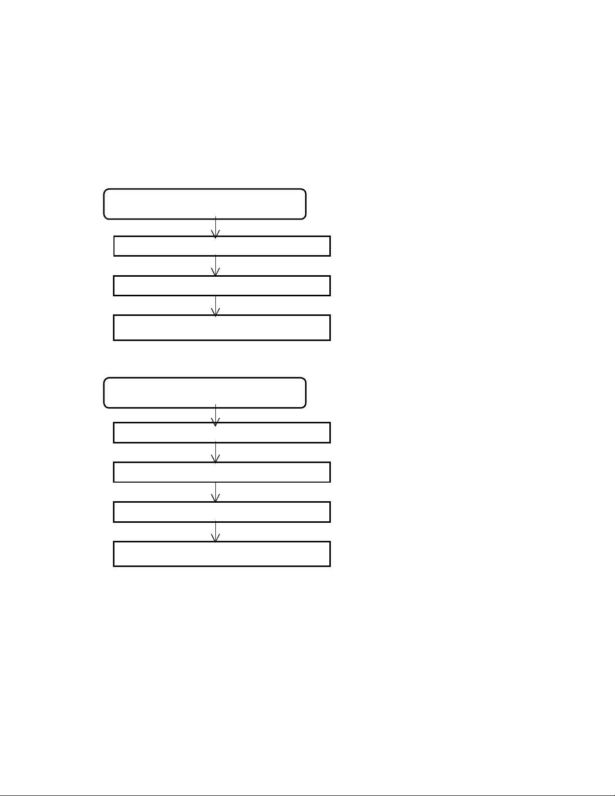
Press ON/OFF switch for 2 seconds to turn instrument on and start warm-up and self-diagnosis .
The program and instrument display function one of the following two ways:
If the detection TAB is not installed before start-up:
Press ON/OFF switch for 2 seconds
BATT E--------l------F Shows the battery capacity
Approx 5 sec
STAND BY OK Standby Condition
Approx 5 sec
SET TAB
If the detection TAB is installed before start-up
Waiting for TAB to be installed and
selected
Press ON/OFF switch for 2 seconds
BATT----------l----F Shows the battery capacity
Approx 5 sec
SELF-DIAGNOSIS Self-diagnosis : Sensor check
Approx 5 sec
STAND BY OK Standby Condition
Approx 5 sec
SELECT TAB No
Select the detection TAB for desired range
using up/down button.
Page 4
3
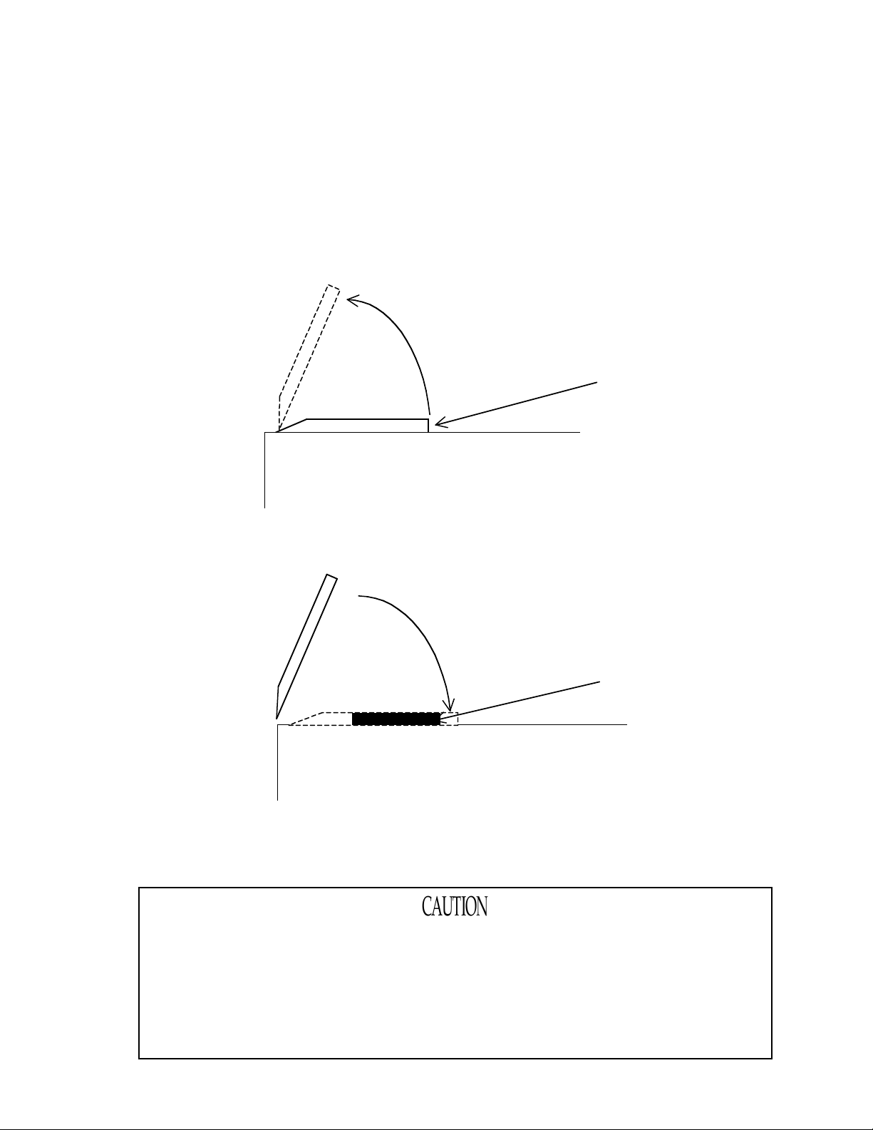
1.2 Installation of Detection Tab
L
D
I
C
I
The detection TAB comes packaged in a sealed foil wrapper. Remove it from the wrapper. The detection
surface of the TAB is protected by a plastic cover that fits over the TAB. Remove this cover. The
detection TAB must only be handled by its edges or backside. Do not touch the indented center section
of the TAB.
1. Open the detection TAB cover.
ift up this way.
etection TAB cover
nstrument (Side view)
2. Place the TAB into the slot under the cover, indented face down, and then close the cover
slowly.
lose the cover.
Detection TAB
nstrument (Side view)
3. Press the center of detection TAB cover with finger to assure proper TAB seating.
When closing the detection TAB cover, close it slowly to avoid pinching finger.
Do not allow the lid to slam shut since that may cause damage to the
instrument.
When installing the detection TAB, do not allow water drops or dust to get in
the TAB port area.
Page 5
4
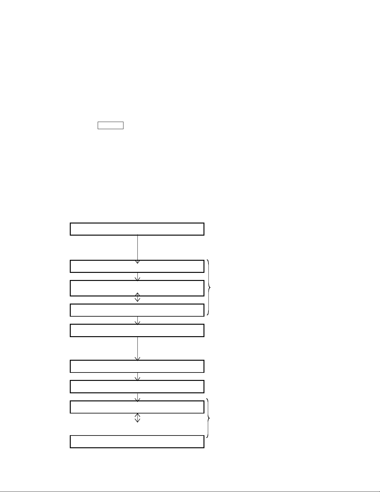
1.3 Detection Method
Gas detection
• Detection waiting condition
The instrument waits in this mode until the detection TAB is installed.
• Installation of the detection TAB
Install the detection TAB.
• Selection of the detection range
Select the detection range by pressing up/down keys.
• Detection starts
Press START
minutes or 30 minutes (as selected).
• Display of detection result
After the detection cycle is completed, the average gas reading during the detection cycle is
shown as the detection result.
• Display of memory number
The number recorded for this reading in the memory is displayed.
• Completion of detection
The gas reading and message will alternately be shown until the used detection
tab is removed. Buzzer sounds every one second until used tab is removed.
Display example
switch to start the pump and start the detection cycle. Cycle is either 15
SET 1 Detection waiting condition
2 Install the detection TAB
SELECT TAB No
008 : HCHO START
008 : HCHO PUSH
008 : HCHO 1800 4 Start
Counting down the detection time. (Sec.)
008 : HCHO 0.100 5 Display of detection result
MO5 REGISTERED 6 Memory number display
REMOVE TAB
beep beep 7 Completion of detection
2 Select the detection TAB (time/range
selection) using the up/down keys.
008 : HCHO 0.100
Page 6

5
NOTE
Only one type of detection TAB is used in the FP-30 & FP-40, but the TAB may be used
for three different detection ranges. For the FP-30, select the TAB No. according to the
desired detection range. The FP-40 can only be used for one detection range.
Detection range Measuring time TAB No.
0 - 0.4 ppm (FP-30) 30 min. 008
0 – 1.0 ppm (FP-30 15 min. 009
0 - 0.6 ppm (FP-40) 3 min 010
• Do not remove tab during detection.
If TAB is removed during detection, the detection is interrupted, and that
cycle cannot be restarted with a new TAB. The error message TAB is
displayed. The old TAB must be discarded and replaced with a new one
before a new cycle is started.
• When the detection range is changed for a new cycle, be sure to exhaust
the inside gas by pre-sample drawing from the instrument (see Section
1.7 Preliminary Sample Draw Mode) to flush out any residual gas
concentrations inside the unit. If high-density gas remains inside the FP30 then it may affect the next gas detection cycle.
• Do not suck water or oil into the instrument since this will cause pump and
instrument damage.
• When detecting gas, confirm that the pump is working by listening to the
humming sound of the pump or confirming that the pump is sucking. If the
pump is not sucking, no gas detection will occur.
• Do not block the gas outlet, or else an incorrect gas reading may result.
Page 7

6
1.4 High Density Gas Detection
If high-density gas is detected, the instrument and any sample hose must be flushed out with fresh air
before installing a new detection tablet. If a new detection tab is installed immediately without flushing
the instrument (and sample hose) out with fresh air, the wrong answer will occur since detection will
start immediately when the new tab in installed. (SEE PRELIMINARY SAMPLE DRAW, STEP 1.7)
1.5 Memory of Stored Gas Detection Results
1.5.1 Checking Stored Data
The past detection results can be displayed by pressing DATA
condition or detection finished condition.
The detection results will be stored into the instrument memory (up to 99 readings maximum). The
memory can be retrieved by using the UP and DOWN keys. When power is off, the memory is retained.
To return to the detection waiting condition or detection finished condition, press DATA
When the DATA
The detection result memory can store only the past 99 readings. If the memory is full, the display will
say:
For deletion of measuring results stored in memory, see the next page.
If there is no stored data, the display will say:
switch is pressed, the most recent record is displayed.
M05 : HCHO 0.100
DATA FULL
DATA EMPTY
switch when in the detection waiting
switch again.
Page 8

7
1.5.2 Deleting the Memory of Stored Detection Results
To delete the memory:
While in the data display screen described above in 1.5.1, press the START
simultaneously. The message to delete the stored detection results is displayed.
Then, when START
If DATA
deleting the data.
Display every 4 sec.
Display every 1 sec.
switch is pressed instead, the instrument will return to the previous condition without
• It is impossible to delete an individual detection result.
• All detection results are deleted simultaneously, and once deleted they are
switch is pressed, all the stored detection results are deleted.
DELETE START
Display every 1 sec.
DELETE PUSH
STORE DATA
STORE PUSH
not recoverable.
+ DATA switches
1.6 Battery Voltage Check
By pressing DATA switch for 3 sec while in detection waiting condition or detection finished mode,
the current battery voltage can be checked. If 20 seconds elapses without any switch being pressed
while in the battery voltage check screen, the instrument will return to the state it was in, either
detection standby condition or detection finished mode.
To return to the detection waiting or detection finished mode, press DATA
BATT E----------l------F
switch again.
1.7 Preliminary Sample Draw Mode
When detection gas mode is changed, or if a high gas concentration was last detected with the
instrument, it is possible the next gas detection test will be influenced by high-density gas
remaining inside the instrument. To prevent this, it is necessary to flush the instrument using the
preliminary sample-drawing mode.
Page 9

8
Preliminary sample drawing method
With detection TAB removed, press START
Preliminary sample drawing is made for about 5 sec to flush out the previous sample, and the following
message is displayed until completion.
Previous sample drawing
Preliminary sample drawing must be done in fresh air , or in the air of the room
switch.
you will check next.
1.8 Purge Cycle
When sample-drawing an adsorptive gas continuously, there is the possibility the gas will be adsorbed
onto the inside of the tubing, especially if a high concentration of gas is encountered. If a high
concentration of gas is encountered, the system must be purged in known fresh air before taking a
reading. After purge, the gas detection cycle will start automatically.
Purging method
Mount the detection TAB, select the purge cycle by using UP and DOWN keys. A used TAB may be
used for the purge cycle.
PURGE S T A R T
PURGE P U S H
When START switch is pressed, the purging starts. for 10 minutes
PURGE 600
When 10 min (600 sec.) passes, the purge cycle is finished and the unit is ready to start the next gas
detection cycle.
REMOVE TAB
Count down 600 sec.
1.9 Completion of Detection
HOW TO TURN INSTRUMENT POWER OFF
To turn instrument off, press and hold ON/OFF
When pressing ON/OFF
Also, if 5 minutes passes without any button being pressed, or when 5 minutes has elapsed since the last
operation, the power will shut off automatically.
switch, the buzzer sounds about 9 times.
switch for about 3 sec.
Page 10

9
2 ABOUT THE DETECTION TAB
The Gas Detection Tablet is a unique detection method developed by our company. The tablet contains a
paper impregnated with special chemicals that will darken if exposed to a specific gas.
Proper storage of the tablet is critical. If tablet is not stored correctly, the detection results will not be
accurate.
2.1 Storage of Detection TAB
Detection TAB must be used within the storage period indicated on the package.
Use of tablets beyond their expiration date can result in incorr ect readings.
Leave detection TAB in its package until ready for use. Once a tablet is removed
from its packet, it will begin drying out, and also it may respond to gas in the local
environment causing error if used for any actual test.
Follow the storage instructions on the detection TAB package. Detection tabs must be stored in a
refrigerator for longest life.
If detection tab is removed from its package and not used right away, it must be discarded. It will give
an incorrect reading if used later. Prolonged exposure to air or background gas will dry out the tablet or
cause it to become discolored, either of which will cause an incorrect reading.
2.2 Handling of Detection TAB
Do not touch the test paper of the detection TAB.
____ ___Test paper (White) Ring (Black) TAB No & Gas name etc
Do not touch the test paper with your finger; this will cause an incorrect reading.
Page 11

1
Always use a new detection TAB for readings
For each gas test, be sure to use new detection TAB. TABS are intended for one time use only, and
should not be opened until immediately before you intend to use them. If an already used TAB is
attempted to be used, an error message “TAB” may be shown. But, even if the error message is not
displayed, the detection result will not be correct if an old TAB is used.
Use TAB immediately after removing from package.
After unpacking the detection TAB, it is subject to gas response and dust, which discolors the TAB due
to response to the measured. To maintain accuracy, start measurement immediately after unpacking.
_
Check that the number of the detection TAB corresponds to the TAB number of
displayed on FP-30 during the Start Measurement display.
If the TAB used is not the same TAB number the instrument believes you are using, the reading will not
be correct.
0
Page 12

1
3 SELF DIAGNOSIS FUNCTION
A Self-diagnosis function is provided with this instrument.
Each self-diagnosis mode has a unique alarm, display, and buzzer sound.
Types of self-diagnosis and alarm pattern
Self diagnosis Buzzer Display
Power on
Low battery precaution No sound Flickering “B” at left
During gas detection
Failure of pump connection Continuous PUMP FAILURE
Low battery voltage Continuous REPLACE BATTERY
System error No sound SYSTEM ERROR
Sensor failure Continuous FAIL
Lower battery voltage Continuous REPLACE BATTERY
TAB detachment No sound RESET TAB
TAB FAILURE
Defective TAB Continuous
and
REPLACE TAB
1
Page 13

1
4 MAINTENANCE
4.1 Battery Replacement
When replacing batteries, replace all 4 batteries at the same time.
• Turn power off.
• Remove the carrying case from instrument.
• Press the battery cover slightly and slide it off.
• Remove all 4 batteries and install the new batteries. Take care to use correct polarity and
battery type.
• After replacing batteries, replace cover and carrying case.
4.2 Daily Check/Regular Check
Daily check
• Checking switches, display and body for any physical damage.
• Pump suction check. Is pump running sound normal ?
• Check battery voltage.
• Sensor check: Instrument performs a sensor check duding warm up whenever first turned
on.
4.3 Replacement of Parts
The following parts have a limited life and it is recommended that they be replaced regularly.
Pump : About 1 year (field replaceable)
Sensor : About 5 years (factory replaceable only. Requires special tools and calibration)
4.4 Storage and Treatment After Long Term Storage
Store in a cool dry place and out of direct sunlight.
If storing for a long period, remove batteries before storage.
2
Page 14

1
5 TROUBLE SHOOTING
This trouble-shooting guide cannot cover all possible malfunctions. The most likely problems and
causes are listed below.
Symptom (Message) Cause Treatment
Low battery (REPLACE BATTERY) Battery voltage is low. Replace Batteries
Sensor failure (FAIL)
Pump failure
(PUMP FAILURE)
System error of instrument
(SYSTEM ERROR)
Detachment of TAB
(RESET TAB)
Failure of TAB.
(TAB FAILURE)
(REPLACE TAB)
Power will not turn on.
Excessive shock such as
dropping, or extensive use
for a long time.
Remove the detection TAB
during sensor check.
Excessive shock such as
dropping, or extensive use
for a long time.
Possible influence by high
EMI or RFI signal, or other
electrical problem.
Remove TAB.
The initial condition of
TAB is not normal.
Batteries need replacement
or no batteries installed.
Battery polarity is wrong.
On/Off switch not held long
enough.
Turn on power again and repeat
the sensor check. If it does not
recover, return to factory for
repair.
Replace TAB and turn on the
power. Re-check the sensor.
Turn power on again.
If not recovered, replace pump or
return unit to factory for repair.
Turn power on again. If not
recovered, return to factory for
repair.
Remove /replace tab after gas
detection cycle is complete.
Use new TAB.
Replace or install batteries
correctly.
Press switch for approx. 2 sec.
(Until instrument turns on)
Pump not working.
Sample cannot be drawn
The battery capacity is too
low.
The sampling hose is
disconnected or clogged.
Replace batteries and try again.
Check the connection of sampling
hose. Check for clogged hose.
3
Page 15

1
6 SPECIFICATIONS
6.1 Specifications
Model______
Detection principle Photoelectric photometry method
Display method Digital display by LCD.
Sampling method Sample-drawing by pump
Memory function 99 points logged. (Automatic recording after detection)
Ambient temp -10 to +40 C, 90% RH (Non-condensing)
Power source AA size Dry battery, 4 ea.
Continuous duty
Regulatory NOT explosion proof or intrinsically safe.
Dimensions
W eight Approx. 550g (Including instrument and batteries)
FP-30, FP-40
Approx. 12 hours (with Alkaline battery, no alarm or illumination and
at 20 C
Approx. 85(W)
protrusions)
190(H) 40(D) mm (not including instrument
6.2 Accessories
Standard accessories:
• Carrying case
• AA size battery
• 1 pack of 20 tablets
• Instruction manual
Optional accessories_
• Additional detection tablets (20 / pack)
• Software for data logger
• Exclusive cable for data logger
6.3 Spare Parts List
Part Number Description
65-TAB-008 Detection TAB, type 008/009/010
71-0085RK Operator’s Manual (this document)
4
Page 16

1
6.4 7 DETECTION PRINCIPLE
P
G
G
The Gas detection TAB test paper is treated with special chemicals and an illuminating agent.
When gas is blown onto the TAB paper face, the paper emits illumination by chemical reaction, and this
causes the paper to change color. The amount of color change is determined by the level of
formaldehyde exposure, and the time of exposure.
For example, when formaldehyde (HCHO) contacts the paper, chemicals impregnated into the
paper combine with HCHO to form compounds, and these compounds change the paper from white to
yellow color.
The instrument creates a light beam that reflects off the test paper at the end of the detection cycle. The
intensity of the light beam is affected by the color or darkness of the detection TAB paper, and this
intensity is measured by a light sensor. The level of light intensity measured is correlated (from an
exposure curve stored in the instrument) to a particular level of Formaldehyde exposure to the tab. This
concentration is then displayed at the end of the detection cycle.
Detection
TAB
Light (LED)
Chamber
AS IN
AS OUT
hoto sensor (Photo diode)
5
 Loading...