

Page 1

EAGLE 2
Operator’s Manual
Part Number: 71-0154RK
Revision: CC
Released: 3/12/19
www.rkiinstruments.com
Page 2

WARNING
Read and understand this instruction manual before
operating instrument. Improper use of the gas
monitor could result in bodily harm or death.
Periodic calibration and maintenance of the gas
monitor is essential for proper operation and correct
readings. Please calibrate and maintain this
instrument regularly! Frequency of calibration
depends upon the type of use y ou have and th e sensor
types. Typical calibration frequencie s for most
applications are between 1 and 3 months, but can be
required more often or less often based on your usage.
EAGLE 2 Operator’s Manual
Page 3

Table of Contents
Chapter 1: Introduction . . . . . . . . . . . . . . . . . . . . . . . . . . . . . . . . . . . . . . . . . . . . . . . . . . . . . . 10
Overview . . . . . . . . . . . . . . . . . . . . . . . . . . . . . . . . . . . . . . . . . . . . . . . . . . . . . . . . . . . . . 10
About the EAGLE 2 . . . . . . . . . . . . . . . . . . . . . . . . . . . . . . . . . . . . . . . . . . . . . . . . . . . . 10
Specifications . . . . . . . . . . . . . . . . . . . . . . . . . . . . . . . . . . . . . . . . . . . . . . . . . . . . . . . . . . 12
About this Manual . . . . . . . . . . . . . . . . . . . . . . . . . . . . . . . . . . . . . . . . . . . . . . . . . . . . . . 13
Chapter 2: Description . . . . . . . . . . . . . . . . . . . . . . . . . . . . . . . . . . . . . . . . . . . . . . . . . . . . . . . 14
Overview . . . . . . . . . . . . . . . . . . . . . . . . . . . . . . . . . . . . . . . . . . . . . . . . . . . . . . . . . . . . . 14
Instrument Description . . . . . . . . . . . . . . . . . . . . . . . . . . . . . . . . . . . . . . . . . . . . . . . . . . 14
Case . . . . . . . . . . . . . . . . . . . . . . . . . . . . . . . . . . . . . . . . . . . . . . . . . . . . . . . . . . . 16
Sensors . . . . . . . . . . . . . . . . . . . . . . . . . . . . . . . . . . . . . . . . . . . . . . . . . . . . . . . . . 16
LCD . . . . . . . . . . . . . . . . . . . . . . . . . . . . . . . . . . . . . . . . . . . . . . . . . . . . . . . . . . . 17
Control Buttons . . . . . . . . . . . . . . . . . . . . . . . . . . . . . . . . . . . . . . . . . . . . . . . . . . 17
Printed Circuit Boards (PCBs) . . . . . . . . . . . . . . . . . . . . . . . . . . . . . . . . . . . . . . 18
Alarm LEDs . . . . . . . . . . . . . . . . . . . . . . . . . . . . . . . . . . . . . . . . . . . . . . . . . . . . . 19
Infrared Communications Port . . . . . . . . . . . . . . . . . . . . . . . . . . . . . . . . . . . . . . 19
Buzzer . . . . . . . . . . . . . . . . . . . . . . . . . . . . . . . . . . . . . . . . . . . . . . . . . . . . . . . . . . 20
Battery Case & Batteries . . . . . . . . . . . . . . . . . . . . . . . . . . . . . . . . . . . . . . . . . . . 20
Flow System . . . . . . . . . . . . . . . . . . . . . . . . . . . . . . . . . . . . . . . . . . . . . . . . . . . . . 20
Standard Accessories . . . . . . . . . . . . . . . . . . . . . . . . . . . . . . . . . . . . . . . . . . . . . . . . . . . . 21
Shoulder Strap . . . . . . . . . . . . . . . . . . . . . . . . . . . . . . . . . . . . . . . . . . . . . . . . . . . 21
Hose and Probe . . . . . . . . . . . . . . . . . . . . . . . . . . . . . . . . . . . . . . . . . . . . . . . . . . 21
Optional Accessories . . . . . . . . . . . . . . . . . . . . . . . . . . . . . . . . . . . . . . . . . . . . . . . . . . . . 23
Rechargeable Ni-MH Batteries . . . . . . . . . . . . . . . . . . . . . . . . . . . . . . . . . . . . . . 23
Battery Chargers . . . . . . . . . . . . . . . . . . . . . . . . . . . . . . . . . . . . . . . . . . . . . . . . . 23
Optional Probes . . . . . . . . . . . . . . . . . . . . . . . . . . . . . . . . . . . . . . . . . . . . . . . . . . 24
External Dilution Fittings . . . . . . . . . . . . . . . . . . . . . . . . . . . . . . . . . . . . . . . . . . 26
Chapter 3: Operation . . . . . . . . . . . . . . . . . . . . . . . . . . . . . . . . . . . . . . . . . . . . . . . . . . . . . . . . . 27
Overview . . . . . . . . . . . . . . . . . . . . . . . . . . . . . . . . . . . . . . . . . . . . . . . . . . . . . . . . . . . . . 27
Start Up . . . . . . . . . . . . . . . . . . . . . . . . . . . . . . . . . . . . . . . . . . . . . . . . . . . . . . . . . . . . . . 27
Turning On the EAGLE 2 . . . . . . . . . . . . . . . . . . . . . . . . . . . . . . . . . . . . . . . . . . . 27
Performing a Demand Zero . . . . . . . . . . . . . . . . . . . . . . . . . . . . . . . . . . . . . . . . . 31
Turning Off the EAGLE 2 . . . . . . . . . . . . . . . . . . . . . . . . . . . . . . . . . . . . . . . . . . 32
Using the Battery Charger for Continuous Operation . . . . . . . . . . . . . . . . . . . . . . . . . . . 32
Measuring Mode, Normal Operation . . . . . . . . . . . . . . . . . . . . . . . . . . . . . . . . . . . . . . . . 33
Monitoring an Area . . . . . . . . . . . . . . . . . . . . . . . . . . . . . . . . . . . . . . . . . . . . . . . 33
Using Optional Sample Hoses . . . . . . . . . . . . . . . . . . . . . . . . . . . . . . . . . . . . . . . 34
Using Exhaust Tubing . . . . . . . . . . . . . . . . . . . . . . . . . . . . . . . . . . . . . . . . . . . . . 34
Combustible Gas Detection . . . . . . . . . . . . . . . . . . . . . . . . . . . . . . . . . . . . . . . . . 34
Monitoring Combustible Gas in the PPM or %Volume Ranges. . . . . . . . . . . . . . 36
Measuring Mode, Alarms . . . . . . . . . . . . . . . . . . . . . . . . . . . . . . . . . . . . . . . . . . . . . . . . 38
Alarm Indications . . . . . . . . . . . . . . . . . . . . . . . . . . . . . . . . . . . . . . . . . . . . . . . . . 38
Resetting and Silencing Alarms . . . . . . . . . . . . . . . . . . . . . . . . . . . . . . . . . . . . . . 39
Responding to Alarms . . . . . . . . . . . . . . . . . . . . . . . . . . . . . . . . . . . . . . . . . . . . . 40
EAGLE 2 Operator’s Manual Table of Contents
Page 4

Display Mode . . . . . . . . . . . . . . . . . . . . . . . . . . . . . . . . . . . . . . . . . . . . . . . . . . . . . . . . . . 41
Tips for Using Display Mode . . . . . . . . . . . . . . . . . . . . . . . . . . . . . . . . . . . . . . . . 42
Peak Screen . . . . . . . . . . . . . . . . . . . . . . . . . . . . . . . . . . . . . . . . . . . . . . . . . . . . . 42
Battery Voltage Screen . . . . . . . . . . . . . . . . . . . . . . . . . . . . . . . . . . . . . . . . . . . . . 43
Gas Display Screen . . . . . . . . . . . . . . . . . . . . . . . . . . . . . . . . . . . . . . . . . . . . . . . 43
Catalytic (LEL) Sensor Screen . . . . . . . . . . . . . . . . . . . . . . . . . . . . . . . . . . . . . . . 44
Methane Elimination Mode Screen . . . . . . . . . . . . . . . . . . . . . . . . . . . . . . . . . . . 44
Relative Response Screen . . . . . . . . . . . . . . . . . . . . . . . . . . . . . . . . . . . . . . . . . . . 44
STEL Screen . . . . . . . . . . . . . . . . . . . . . . . . . . . . . . . . . . . . . . . . . . . . . . . . . . . . . 46
TWA Screen . . . . . . . . . . . . . . . . . . . . . . . . . . . . . . . . . . . . . . . . . . . . . . . . . . . . . 46
View Alarm Settings Screen . . . . . . . . . . . . . . . . . . . . . . . . . . . . . . . . . . . . . . . . . 47
Select User ID Screen . . . . . . . . . . . . . . . . . . . . . . . . . . . . . . . . . . . . . . . . . . . . . 48
Select Station ID Screen . . . . . . . . . . . . . . . . . . . . . . . . . . . . . . . . . . . . . . . . . . . . 49
Time in Operation Screen . . . . . . . . . . . . . . . . . . . . . . . . . . . . . . . . . . . . . . . . . . 50
Date/Time Screen . . . . . . . . . . . . . . . . . . . . . . . . . . . . . . . . . . . . . . . . . . . . . . . . . 51
Data Logging Screen . . . . . . . . . . . . . . . . . . . . . . . . . . . . . . . . . . . . . . . . . . . . . . 51
Data Logging . . . . . . . . . . . . . . . . . . . . . . . . . . . . . . . . . . . . . . . . . . . . . . . . . . . . . . . . . . 52
Chapter 4: Calibration Mode . . . . . . . . . . . . . . . . . . . . . . . . . . . . . . . . . . . . . . . . . . . . . . . . . . 54
Overview . . . . . . . . . . . . . . . . . . . . . . . . . . . . . . . . . . . . . . . . . . . . . . . . . . . . . . . . . . . . . 54
Calibration Supplies and Equipment . . . . . . . . . . . . . . . . . . . . . . . . . . . . . . . . . . . . . . . . 55
Entering Calibration Mode . . . . . . . . . . . . . . . . . . . . . . . . . . . . . . . . . . . . . . . . . . . . . . . 56
Calibrating Using the Auto Calibration Method . . . . . . . . . . . . . . . . . . . . . . . . . . . . . . . 56
Setting the Fresh Air Reading . . . . . . . . . . . . . . . . . . . . . . . . . . . . . . . . . . . . . . . 56
Performing a Span Adjustment in Auto Calibration . . . . . . . . . . . . . . . . . . . . . . 58
Calibrating Using the Single Calibration Method . . . . . . . . . . . . . . . . . . . . . . . . . . . . . . 62
Setting the Fresh Air Reading . . . . . . . . . . . . . . . . . . . . . . . . . . . . . . . . . . . . . . . 62
Performing a Span Adjustment in Single Calibration . . . . . . . . . . . . . . . . . . . . . 63
Chapter 5: Maintenance . . . . . . . . . . . . . . . . . . . . . . . . . . . . . . . . . . . . . . . . . . . . . . . . . . . . . . 67
Overview . . . . . . . . . . . . . . . . . . . . . . . . . . . . . . . . . . . . . . . . . . . . . . . . . . . . . . . . . . . . . 67
Troubleshooting . . . . . . . . . . . . . . . . . . . . . . . . . . . . . . . . . . . . . . . . . . . . . . . . . . . . . . . . 67
Replacing or Recharging the Batteries . . . . . . . . . . . . . . . . . . . . . . . . . . . . . . . . . . . . . . 69
Replacing the Batteries . . . . . . . . . . . . . . . . . . . . . . . . . . . . . . . . . . . . . . . . . . . . 69
Recharging the Ni-MH Batteries . . . . . . . . . . . . . . . . . . . . . . . . . . . . . . . . . . . . . 70
Replacing the Hydrophobic Probe’s Particle Filter and Hydrophobic Filter Disk . . . . . 72
Replacing the Hydrophobic Filter . . . . . . . . . . . . . . . . . . . . . . . . . . . . . . . . . . . . . . . . . . 73
Replacing the Charcoal Filter . . . . . . . . . . . . . . . . . . . . . . . . . . . . . . . . . . . . . . . . . . . . . 75
Checking the Combustible Gas Sensor’s Condition . . . . . . . . . . . . . . . . . . . . . . . . . . . . 76
Replacing a Sensor . . . . . . . . . . . . . . . . . . . . . . . . . . . . . . . . . . . . . . . . . . . . . . . . . . . . . . 76
General Parts List . . . . . . . . . . . . . . . . . . . . . . . . . . . . . . . . . . . . . . . . . . . . . . . . . . . . . . . 79
Appendix A: Calibrating with a Sample Bag . . . . . . . . . . . . . . . . . . . . . . . . . . . . . . . . . . . . . 82
Overview . . . . . . . . . . . . . . . . . . . . . . . . . . . . . . . . . . . . . . . . . . . . . . . . . . . . . . . . . . . . . 82
Calibration Supplies and Equipment . . . . . . . . . . . . . . . . . . . . . . . . . . . . . . . . . . . . . . . . 82
Entering Calibration Mode . . . . . . . . . . . . . . . . . . . . . . . . . . . . . . . . . . . . . . . . . . . . . . . 83
Calibrating Using the Auto Calibration Method . . . . . . . . . . . . . . . . . . . . . . . . . . . . . . . 84
Setting the Fresh Air Reading . . . . . . . . . . . . . . . . . . . . . . . . . . . . . . . . . . . . . . . 84
Performing a Span Adjustment in Auto Calibration . . . . . . . . . . . . . . . . . . . . . . 85
Ta ble of Contents EAGLE 2 Operator’s Manual
Page 5

Calibrating Using the Single Calibration Method . . . . . . . . . . . . . . . . . . . . . . . . . . . . . . 89
Setting the Fresh Air Reading . . . . . . . . . . . . . . . . . . . . . . . . . . . . . . . . . . . . . . . 89
Performing a Span Adjustment in Single Calibration . . . . . . . . . . . . . . . . . . . . . 90
Parts List . . . . . . . . . . . . . . . . . . . . . . . . . . . . . . . . . . . . . . . . . . . . . . . . . . . . . . . . . . . . . 94
Appendix B: Setup Mode . . . . . . . . . . . . . . . . . . . . . . . . . . . . . . . . . . . . . . . . . . . . . . . . . . . . . 95
Overview . . . . . . . . . . . . . . . . . . . . . . . . . . . . . . . . . . . . . . . . . . . . . . . . . . . . . . . . . . . . . 95
Tips for Using Setup Mode . . . . . . . . . . . . . . . . . . . . . . . . . . . . . . . . . . . . . . . . . . . . . . . 96
Using Setup Mode . . . . . . . . . . . . . . . . . . . . . . . . . . . . . . . . . . . . . . . . . . . . . . . . . . . . . . 96
Setting the Date and Time . . . . . . . . . . . . . . . . . . . . . . . . . . . . . . . . . . . . . . . . . . 97
Setting the Date Format . . . . . . . . . . . . . . . . . . . . . . . . . . . . . . . . . . . . . . . . . . . . 98
Setting the Battery Type . . . . . . . . . . . . . . . . . . . . . . . . . . . . . . . . . . . . . . . . . . . . 98
Configuring the Channels . . . . . . . . . . . . . . . . . . . . . . . . . . . . . . . . . . . . . . . . . . 99
Configuring the Combustible Gas . . . . . . . . . . . . . . . . . . . . . . . . . . . . . . . . . . . 101
Setting the Catalytic Detection Units . . . . . . . . . . . . . . . . . . . . . . . . . . . . . . . . . 105
Updating the Relative Response Setting . . . . . . . . . . . . . . . . . . . . . . . . . . . . . . 106
Updating the Alarm Point Settings . . . . . . . . . . . . . . . . . . . . . . . . . . . . . . . . . . 106
Updating the Alarm Latching Setting . . . . . . . . . . . . . . . . . . . . . . . . . . . . . . . . 108
Updating the Alarm Silence Setting . . . . . . . . . . . . . . . . . . . . . . . . . . . . . . . . . . 108
Turning the User/Station ID Function On or Off . . . . . . . . . . . . . . . . . . . . . . . . 109
Updating the Autocal Values . . . . . . . . . . . . . . . . . . . . . . . . . . . . . . . . . . . . . . . 109
Updating the Backlight Delay Setting . . . . . . . . . . . . . . . . . . . . . . . . . . . . . . . . 110
Updating the Auto Fresh Air Setting . . . . . . . . . . . . . . . . . . . . . . . . . . . . . . . . . 110
Updating the Data Log Interval Setting . . . . . . . . . . . . . . . . . . . . . . . . . . . . . . . 111
Updating the Data Log Overwrite Setting . . . . . . . . . . . . . . . . . . . . . . . . . . . . . 111
Updating the Data Log Memory Setting . . . . . . . . . . . . . . . . . . . . . . . . . . . . . . 112
Updating the LCD Contrast Setting . . . . . . . . . . . . . . . . . . . . . . . . . . . . . . . . . . 112
Updating the Calibration Reminder Setting . . . . . . . . . . . . . . . . . . . . . . . . . . . 113
Updating the Calibration Past Due Action Setting . . . . . . . . . . . . . . . . . . . . . . 113
Updating the Calibration Interval . . . . . . . . . . . . . . . . . . . . . . . . . . . . . . . . . . . 114
Updating LC/BH Mode Setting . . . . . . . . . . . . . . . . . . . . . . . . . . . . . . . . . . . . . 114
Setting the Bar Hole Measurement Time . . . . . . . . . . . . . . . . . . . . . . . . . . . . . . 115
Zero Follower Settings . . . . . . . . . . . . . . . . . . . . . . . . . . . . . . . . . . . . . . . . . . . . 115
Zero Suppression Settings . . . . . . . . . . . . . . . . . . . . . . . . . . . . . . . . . . . . . . . . . 115
Updating the Confirmation Alert Setting . . . . . . . . . . . . . . . . . . . . . . . . . . . . . . 115
Turning the Password Function On or Off . . . . . . . . . . . . . . . . . . . . . . . . . . . . 116
Restoring the Default Settings . . . . . . . . . . . . . . . . . . . . . . . . . . . . . . . . . . . . . . 117
Updating the Lunch Break Setting . . . . . . . . . . . . . . . . . . . . . . . . . . . . . . . . . . . 118
Updating the Span Factor Setting. . . . . . . . . . . . . . . . . . . . . . . . . . . . . . . . . . . . 119
Updating the Language Setting . . . . . . . . . . . . . . . . . . . . . . . . . . . . . . . . . . . . . 119
Exiting Setup Mode . . . . . . . . . . . . . . . . . . . . . . . . . . . . . . . . . . . . . . . . . . . . . . 120
Appendix C: Sub PCBs . . . . . . . . . . . . . . . . . . . . . . . . . . . . . . . . . . . . . . . . . . . . . . . . . . . . . . 121
Overview. . . . . . . . . . . . . . . . . . . . . . . . . . . . . . . . . . . . . . . . . . . . . . . . . . . . . . . . . . . . . 121
Description . . . . . . . . . . . . . . . . . . . . . . . . . . . . . . . . . . . . . . . . . . . . . . . . . . . . . . . . . . . 121
Channel Setup and Sub PCBs. . . . . . . . . . . . . . . . . . . . . . . . . . . . . . . . . . . . . . . . . . . . . 122
Sub PCBs and CONFIGURE CHANNELS. . . . . . . . . . . . . . . . . . . . . . . . . . . . . 122
Sub PCBs and CONFIGURE GASES. . . . . . . . . . . . . . . . . . . . . . . . . . . . . . . . . 123
EAGLE 2 Operator’s Manual Table of Contents
Page 6

Appendix D: PID Sensors. . . . . . . . . . . . . . . . . . . . . . . . . . . . . . . . . . . . . . . . . . . . . . . . . . . . . 125
Overview. . . . . . . . . . . . . . . . . . . . . . . . . . . . . . . . . . . . . . . . . . . . . . . . . . . . . . . . . . . . . 125
Description . . . . . . . . . . . . . . . . . . . . . . . . . . . . . . . . . . . . . . . . . . . . . . . . . . . . . . . . . . . 125
PID Sensor and Sensor Adapter. . . . . . . . . . . . . . . . . . . . . . . . . . . . . . . . . . . . . 126
PID Sub PCB . . . . . . . . . . . . . . . . . . . . . . . . . . . . . . . . . . . . . . . . . . . . . . . . . . . 126
PID Probe. . . . . . . . . . . . . . . . . . . . . . . . . . . . . . . . . . . . . . . . . . . . . . . . . . . . . . 127
Start Up and Normal Operation . . . . . . . . . . . . . . . . . . . . . . . . . . . . . . . . . . . . . . . . . . . 127
PID Relative Response Feature . . . . . . . . . . . . . . . . . . . . . . . . . . . . . . . . . . . . . . . . . . . 128
PID Sensor Relative Response Screen in Display Mode . . . . . . . . . . . . . . . . . . 129
PID Calibration . . . . . . . . . . . . . . . . . . . . . . . . . . . . . . . . . . . . . . . . . . . . . . . . . . . . . . . . 131
Calibrating with a 4-Gas Cylinder and a PID Cylinder. . . . . . . . . . . . . . . . . . . 131
Calibrating with a 5-Gas Cylinder. . . . . . . . . . . . . . . . . . . . . . . . . . . . . . . . . . . 139
Maintenance . . . . . . . . . . . . . . . . . . . . . . . . . . . . . . . . . . . . . . . . . . . . . . . . . . . . . . . . . . 146
Troubleshooting . . . . . . . . . . . . . . . . . . . . . . . . . . . . . . . . . . . . . . . . . . . . . . . . . 146
Cleaning the PID Sensor’s Lamp . . . . . . . . . . . . . . . . . . . . . . . . . . . . . . . . . . . . 146
Replacing PID Sensor’s Lamp . . . . . . . . . . . . . . . . . . . . . . . . . . . . . . . . . . . . . . 150
Replacing Electrode Stack . . . . . . . . . . . . . . . . . . . . . . . . . . . . . . . . . . . . . . . . . 153
Replacing the PID Sensor. . . . . . . . . . . . . . . . . . . . . . . . . . . . . . . . . . . . . . . . . . 156
Configuring the PID Gas in Setup Mode . . . . . . . . . . . . . . . . . . . . . . . . . . . . . . . . . . . . 157
Parts List . . . . . . . . . . . . . . . . . . . . . . . . . . . . . . . . . . . . . . . . . . . . . . . . . . . . . . . . . . . . . 162
Appendix E: ESM-01 Toxic Sensors . . . . . . . . . . . . . . . . . . . . . . . . . . . . . . . . . . . . . . . . . . . . 164
Overview. . . . . . . . . . . . . . . . . . . . . . . . . . . . . . . . . . . . . . . . . . . . . . . . . . . . . . . . . . . . . 164
Description . . . . . . . . . . . . . . . . . . . . . . . . . . . . . . . . . . . . . . . . . . . . . . . . . . . . . . . . . . . 164
ESM-01 Sensor . . . . . . . . . . . . . . . . . . . . . . . . . . . . . . . . . . . . . . . . . . . . . . . . . . 165
ESM-01 Sub PCB . . . . . . . . . . . . . . . . . . . . . . . . . . . . . . . . . . . . . . . . . . . . . . . . 165
Start Up and Normal Operation . . . . . . . . . . . . . . . . . . . . . . . . . . . . . . . . . . . . . . . . . . . 166
ESM-01 Calibration . . . . . . . . . . . . . . . . . . . . . . . . . . . . . . . . . . . . . . . . . . . . . . . . . . . . 166
Calibrating with a 4-Gas Cylinder and an ESM-01 Cylinder . . . . . . . . . . . . . . 166
Calibrating with a 5-Gas Cylinder. . . . . . . . . . . . . . . . . . . . . . . . . . . . . . . . . . . 174
Maintenance . . . . . . . . . . . . . . . . . . . . . . . . . . . . . . . . . . . . . . . . . . . . . . . . . . . . . . . . . . 180
Replacing the ESM-01 Sensor . . . . . . . . . . . . . . . . . . . . . . . . . . . . . . . . . . . . . . 180
Replacing the H2S Scrubber in the SO2 and HCN Sensors . . . . . . . . . . . . . . . . 181
Parts List . . . . . . . . . . . . . . . . . . . . . . . . . . . . . . . . . . . . . . . . . . . . . . . . . . . . . . . . . . . . . 183
Appendix F: TC Sensors . . . . . . . . . . . . . . . . . . . . . . . . . . . . . . . . . . . . . . . . . . . . . . . . . . . . . 184
Overview. . . . . . . . . . . . . . . . . . . . . . . . . . . . . . . . . . . . . . . . . . . . . . . . . . . . . . . . . . . . . 184
Description . . . . . . . . . . . . . . . . . . . . . . . . . . . . . . . . . . . . . . . . . . . . . . . . . . . . . . . . . . . 184
TC Sensor . . . . . . . . . . . . . . . . . . . . . . . . . . . . . . . . . . . . . . . . . . . . . . . . . . . . . . 185
TC Sub PCB . . . . . . . . . . . . . . . . . . . . . . . . . . . . . . . . . . . . . . . . . . . . . . . . . . . . 185
Start Up and Normal Operation . . . . . . . . . . . . . . . . . . . . . . . . . . . . . . . . . . . . . . . . . . . 186
Catalytic (LEL) Sensor Screen . . . . . . . . . . . . . . . . . . . . . . . . . . . . . . . . . . . . . . . . . . . . 186
TC Calibration . . . . . . . . . . . . . . . . . . . . . . . . . . . . . . . . . . . . . . . . . . . . . . . . . . . . . . . . 187
Maintenance . . . . . . . . . . . . . . . . . . . . . . . . . . . . . . . . . . . . . . . . . . . . . . . . . . . . . . . . . . 193
Replacing the TC Sensor. . . . . . . . . . . . . . . . . . . . . . . . . . . . . . . . . . . . . . . . . . . 193
Configuring the TC Gas in Setup Mode . . . . . . . . . . . . . . . . . . . . . . . . . . . . . . . . . . . . . 195
Parts List . . . . . . . . . . . . . . . . . . . . . . . . . . . . . . . . . . . . . . . . . . . . . . . . . . . . . . . . . . . . . 199
Ta ble of Contents EAGLE 2 Operator’s Manual
Page 7

Appendix G: Infrared Carbon Dioxide Sensors . . . . . . . . . . . . . . . . . . . . . . . . . . . . . . . . . . 200
Overview. . . . . . . . . . . . . . . . . . . . . . . . . . . . . . . . . . . . . . . . . . . . . . . . . . . . . . . . . . . . . 200
Description . . . . . . . . . . . . . . . . . . . . . . . . . . . . . . . . . . . . . . . . . . . . . . . . . . . . . . . . . . . 200
Infrared Carbon Dioxide Sensor. . . . . . . . . . . . . . . . . . . . . . . . . . . . . . . . . . . . . 201
Infrared Sub PCB . . . . . . . . . . . . . . . . . . . . . . . . . . . . . . . . . . . . . . . . . . . . . . . . 201
CO2 Scrubber . . . . . . . . . . . . . . . . . . . . . . . . . . . . . . . . . . . . . . . . . . . . . . . . . . . 202
Start Up and Normal Operation . . . . . . . . . . . . . . . . . . . . . . . . . . . . . . . . . . . . . . . . . . . 202
Performing a Demand Zero for Carbon Dioxide Sensors . . . . . . . . . . . . . . . . . 203
Infrared Carbon Dioxide Calibration . . . . . . . . . . . . . . . . . . . . . . . . . . . . . . . . . . . . . . . 203
Maintenance . . . . . . . . . . . . . . . . . . . . . . . . . . . . . . . . . . . . . . . . . . . . . . . . . . . . . . . . . . 211
Replacing the IR CO2 Sensor or Changing Sensor Type . . . . . . . . . . . . . . . . . . 211
Parts List . . . . . . . . . . . . . . . . . . . . . . . . . . . . . . . . . . . . . . . . . . . . . . . . . . . . . . . . . . . . . 213
Appendix H: Infrared Methane Sensors. . . . . . . . . . . . . . . . . . . . . . . . . . . . . . . . . . . . . . . . . 214
Overview. . . . . . . . . . . . . . . . . . . . . . . . . . . . . . . . . . . . . . . . . . . . . . . . . . . . . . . . . . . . . 214
Target Gases . . . . . . . . . . . . . . . . . . . . . . . . . . . . . . . . . . . . . . . . . . . . . . . . . . . . 214
Description . . . . . . . . . . . . . . . . . . . . . . . . . . . . . . . . . . . . . . . . . . . . . . . . . . . . . . . . . . . 215
Infrared Methane Sensor . . . . . . . . . . . . . . . . . . . . . . . . . . . . . . . . . . . . . . . . . . 215
Infrared Sub PCB . . . . . . . . . . . . . . . . . . . . . . . . . . . . . . . . . . . . . . . . . . . . . . . . 216
Start Up and Normal Operation . . . . . . . . . . . . . . . . . . . . . . . . . . . . . . . . . . . . . . . . . . . 216
Detection Ranges . . . . . . . . . . . . . . . . . . . . . . . . . . . . . . . . . . . . . . . . . . . . . . . . 216
Catalytic (LEL) Sensor Screen . . . . . . . . . . . . . . . . . . . . . . . . . . . . . . . . . . . . . . . . . . . . 216
Infrared Methane Calibration . . . . . . . . . . . . . . . . . . . . . . . . . . . . . . . . . . . . . . . . . . . . . 217
Maintenance . . . . . . . . . . . . . . . . . . . . . . . . . . . . . . . . . . . . . . . . . . . . . . . . . . . . . . . . . . 224
Replacing the IR Methane Sensor. . . . . . . . . . . . . . . . . . . . . . . . . . . . . . . . . . . . 224
Parts List . . . . . . . . . . . . . . . . . . . . . . . . . . . . . . . . . . . . . . . . . . . . . . . . . . . . . . . . . . . . . 225
Appendix I: Infrared Hydrocarbon Sensor . . . . . . . . . . . . . . . . . . . . . . . . . . . . . . . . . . . . . . 226
Overview. . . . . . . . . . . . . . . . . . . . . . . . . . . . . . . . . . . . . . . . . . . . . . . . . . . . . . . . . . . . . 226
Target Gases . . . . . . . . . . . . . . . . . . . . . . . . . . . . . . . . . . . . . . . . . . . . . . . . . . . . 226
Description . . . . . . . . . . . . . . . . . . . . . . . . . . . . . . . . . . . . . . . . . . . . . . . . . . . . . . . . . . . 226
Infrared Hydrocarbon Sensor. . . . . . . . . . . . . . . . . . . . . . . . . . . . . . . . . . . . . . . 227
Infrared Sub PCB . . . . . . . . . . . . . . . . . . . . . . . . . . . . . . . . . . . . . . . . . . . . . . . . 227
Start Up and Normal Operation . . . . . . . . . . . . . . . . . . . . . . . . . . . . . . . . . . . . . . . . . . . 227
0-100 %LEL/2.0-30.0 %vol Autoranging. . . . . . . . . . . . . . . . . . . . . . . . . . . . . . 227
Catalytic (LEL) Sensor Screen . . . . . . . . . . . . . . . . . . . . . . . . . . . . . . . . . . . . . . . . . . . . 228
Infrared Hydrocarbon Calibration . . . . . . . . . . . . . . . . . . . . . . . . . . . . . . . . . . . . . . . . . 228
Maintenance . . . . . . . . . . . . . . . . . . . . . . . . . . . . . . . . . . . . . . . . . . . . . . . . . . . . . . . . . . 235
Replacing the IR Hydrocarbon Sensor. . . . . . . . . . . . . . . . . . . . . . . . . . . . . . . . 235
Parts List . . . . . . . . . . . . . . . . . . . . . . . . . . . . . . . . . . . . . . . . . . . . . . . . . . . . . . . . . . . . . 236
Appendix J: Methane Elimination Mode . . . . . . . . . . . . . . . . . . . . . . . . . . . . . . . . . . . . . . . . 237
Overview. . . . . . . . . . . . . . . . . . . . . . . . . . . . . . . . . . . . . . . . . . . . . . . . . . . . . . . . . . . . . 237
Monitoring in Methane Elimination Mode. . . . . . . . . . . . . . . . . . . . . . . . . . . . . . . . . . . 237
Calibration . . . . . . . . . . . . . . . . . . . . . . . . . . . . . . . . . . . . . . . . . . . . . . . . . . . . . . . . . . . 240
EAGLE 2 Operator’s Manual Table of Contents
Page 8

Appendix K: Using the EAGLE 2 in Bar Hole Mode . . . . . . . . . . . . . . . . . . . . . . . . . . . . . . 241
Overview. . . . . . . . . . . . . . . . . . . . . . . . . . . . . . . . . . . . . . . . . . . . . . . . . . . . . . . . . . . . . 241
Start Up, Bar Hole Mode . . . . . . . . . . . . . . . . . . . . . . . . . . . . . . . . . . . . . . . . . . . . . . . . 241
Turning on EAGLE 2, Bar Hole Mode . . . . . . . . . . . . . . . . . . . . . . . . . . . . . . . . 241
Performing a Demand Zero, Bar Hole Mode. . . . . . . . . . . . . . . . . . . . . . . . . . . 245
Bar Hole Testing . . . . . . . . . . . . . . . . . . . . . . . . . . . . . . . . . . . . . . . . . . . . . . . . . . . . . . . 246
Performing a Bar Hole Test . . . . . . . . . . . . . . . . . . . . . . . . . . . . . . . . . . . . . . . . 246
Turning off the EAGLE 2, Bar Hole Mode . . . . . . . . . . . . . . . . . . . . . . . . . . . . . 248
Appendix L: Using the EAGLE 2 in Leak Check Mode. . . . . . . . . . . . . . . . . . . . . . . . . . . . 249
Overview. . . . . . . . . . . . . . . . . . . . . . . . . . . . . . . . . . . . . . . . . . . . . . . . . . . . . . . . . . . . . 249
Start Up, Leak Check Mode . . . . . . . . . . . . . . . . . . . . . . . . . . . . . . . . . . . . . . . . . . . . . . 249
Turning On the EAGLE 2, Leak Check Mode. . . . . . . . . . . . . . . . . . . . . . . . . . . 249
Performing a Demand Zero, Leak Check Mode. . . . . . . . . . . . . . . . . . . . . . . . . 254
Leak Testing . . . . . . . . . . . . . . . . . . . . . . . . . . . . . . . . . . . . . . . . . . . . . . . . . . . . . . . . . . 254
Locating a Leak. . . . . . . . . . . . . . . . . . . . . . . . . . . . . . . . . . . . . . . . . . . . . . . . . . 254
Turning the Buzzer On and Off In Leak Check Mode. . . . . . . . . . . . . . . . . . . . . 255
Turning Off the EAGLE 2, Leak Check Mode. . . . . . . . . . . . . . . . . . . . . . . . . . . 255
Appendix M: EAGLE 2 Tank Tester Model. . . . . . . . . . . . . . . . . . . . . . . . . . . . . . . . . . . . . . 256
Description . . . . . . . . . . . . . . . . . . . . . . . . . . . . . . . . . . . . . . . . . . . . . . . . . . . . . . . . . . . 256
Float Probe Assembly. . . . . . . . . . . . . . . . . . . . . . . . . . . . . . . . . . . . . . . . . . . . . 257
Dilution Fitting (1:1) . . . . . . . . . . . . . . . . . . . . . . . . . . . . . . . . . . . . . . . . . . . . . 257
Start Up . . . . . . . . . . . . . . . . . . . . . . . . . . . . . . . . . . . . . . . . . . . . . . . . . . . . . . . . . . . . . . 258
Alarms. . . . . . . . . . . . . . . . . . . . . . . . . . . . . . . . . . . . . . . . . . . . . . . . . . . . . . . . . . . . . . . 259
Calibration . . . . . . . . . . . . . . . . . . . . . . . . . . . . . . . . . . . . . . . . . . . . . . . . . . . . . . . . . . . 260
Parts List . . . . . . . . . . . . . . . . . . . . . . . . . . . . . . . . . . . . . . . . . . . . . . . . . . . . . . . . . . . . . 260
Appendix N: Using the EAGLE 2 in Inert Mode. . . . . . . . . . . . . . . . . . . . . . . . . . . . . . . . . . 261
Description . . . . . . . . . . . . . . . . . . . . . . . . . . . . . . . . . . . . . . . . . . . . . . . . . . . . . . . . . . . 261
Alarms. . . . . . . . . . . . . . . . . . . . . . . . . . . . . . . . . . . . . . . . . . . . . . . . . . . . . . . . . . . . . . . 261
Start Up . . . . . . . . . . . . . . . . . . . . . . . . . . . . . . . . . . . . . . . . . . . . . . . . . . . . . . . . . . . . . . 263
Operation . . . . . . . . . . . . . . . . . . . . . . . . . . . . . . . . . . . . . . . . . . . . . . . . . . . . . . . . . . . . 265
Appendix O: Transformer Gas Tester Model. . . . . . . . . . . . . . . . . . . . . . . . . . . . . . . . . . . . . 266
Description . . . . . . . . . . . . . . . . . . . . . . . . . . . . . . . . . . . . . . . . . . . . . . . . . . . . . . . . . . . 266
Operation . . . . . . . . . . . . . . . . . . . . . . . . . . . . . . . . . . . . . . . . . . . . . . . . . . . . . . . . . . . . 266
Alarms. . . . . . . . . . . . . . . . . . . . . . . . . . . . . . . . . . . . . . . . . . . . . . . . . . . . . . . . . . . . . . . 267
Parts List . . . . . . . . . . . . . . . . . . . . . . . . . . . . . . . . . . . . . . . . . . . . . . . . . . . . . . . . . . . . . 267
Appendix P: Internal Dilution Models . . . . . . . . . . . . . . . . . . . . . . . . . . . . . . . . . . . . . . . . . . 268
Description . . . . . . . . . . . . . . . . . . . . . . . . . . . . . . . . . . . . . . . . . . . . . . . . . . . . . . . . . . . 268
Calibration . . . . . . . . . . . . . . . . . . . . . . . . . . . . . . . . . . . . . . . . . . . . . . . . . . . . . . . . . . . 268
WARNING: Understand manual before operating. Substitution of components may
impair intrinsic safety. To prevent ignition of a hazardous atmosphere,
batteries must only be changed or charged in an area known to be
nonhazardous. Not tested in oxygen enriched atmospheres (above
21%).
Ta ble of Contents EAGLE 2 Operator’s Manual
Page 9

NOTE: RKI Instruments, Inc. recommends that you refer to ISA-RP12.13, Part II-1987
or an equivalent international recommended practice for guidance in the use of
combustible gas detection instruments.
EAGLE 2 Operator’s Manual Table of Contents
Page 10

Chapter 1: Introduction
Overview
This chapter briefly describes the EAGLE 2 gas monitor. This chapter also describes the
EAGLE 2 Operator’s Manual (this document). Table 1 at the end of this chapter lists the
specifications for the EAGLE 2.
About the EAGLE 2
Using an advanced detection system consisting of up to six gas sensors, the EAGLE 2
sample draw gas monitor is capable of detecting the presence of combustible gas, oxygen
(O2), carbon monoxide (CO), hydrogen sulfide (H2S), and various other toxic gases
simultaneously. The EAGLE 2’s rugged, reliable, and easy-to-use design makes it ideally
suited for a wide range of applications, including sewage treatment plants, utility
manholes, tunnels, hazardous waste sites, power stations, petrochemical refineries, mines,
paper mills, drilling rigs, and fire fighting stations. The EAGLE 2 offers a full range of
features including:
• Simultaneous monitoring of one to six gases. The standard configuration includes four
sensors for combustible gas (%LEL, ppm, and %volume), oxygen, carbon monoxide
(CO), and hydrogen sulfide (H2S).
• Choice of three operating modes:
• Normal Mode for typical confined space or area monitoring. Normal Mode is the
standard factory setting.
• Bar Hole Mode for checking of bar holes when searching for underground gas
leaks
• Leak Check Mode for locating leaks in valves and piping
• Sample-drawing pump with up to 125 foot range
• Liquid crystal display (LCD) for complete and understandable information at a glance
• Ultrabright alarm LEDs
• Distinctive audible alarm for dangerous gas conditions or unit malfunction
• Microprocessor control for reliability, ease of use, and advanced capabilities
• Data logging functions (when used in Normal Mode)
• Alarm trend data (when used in Normal Mode)
• STEL and TWA (when used in Normal Mode) and over range alarms
• Peak readings (when used in Normal Mode)
• Built-in time function
• Lunch break feature
• RF shielded high impact plastic case
• CSA classified for Class I, Division I, Groups A, B, C, and D hazardous atmospheres
10 • Overview EAGLE 2 Operator’s Manual
Page 11

WARNING: The Model EAGLE 2 detects oxygen deficiency, elevated levels of
oxygen, combustible gases, carbon monoxide, and hydrogen sulfide, all
of which can be dangerous or life threatening. When u sing the EAGLE
2, you must follow the instructions and warnings in this manual to
assure proper and safe operation of the unit and to mini mize t he risk of
personal injury. Be sure to maintain and periodically calibrate the
EAGLE 2 as described in this manual.
NOTE: ONLY THE COMBUSTIBLE GAS DETECTION PORTION OF THIS
INSTRUMENT HAS BEEN ASSESSED FOR PERFORMANCE.
EAGLE 2 Operator’s Manual About the EAGLE 2 • 11
Page 12

Specifications
Table 1: Standard Sensor Specifications
Combustible Gas,
Methane (CH
)
4
Oxygen (O
) Hydrogen
2
Sulfide (H
Carbon
S)
2
Monoxide (CO)
Calibration Standard
Detection
0 - 100 %LEL 0 - 40 volume% 0 - 100.0 ppm 0 - 500 ppm
Range
Reading
1 %LEL 0.1 volume % 0.5 ppm 1 ppm
Increment
Alarm 1
10 %LEL* 19.5 volume %* 5.0 ppm* 25 ppm*
Factory Setting
Alarm 2
50 %LEL 23.5 volume % 30.0 ppm 50 ppm
Factory Setting
STEL Alarm n/a n/a 5.0 ppm 200 ppm
TWA Alarm n/a n/a 1.0 ppm 25 ppm
* When calibrating the EAGLE 2 with the Auto Calibration or the Single Calibration method, the calibration gas
value must be equal to or higher than the alarm 1 setting. See “Updating the Alarm Point Settings” on page 106
for instructions to change the alarm points if necessary for the desired calibration gas value.
Table 2: EAGLE 2 Specifications
Sampling
Sample Draw
Method
Response
T90 Within 30 Seconds
Time
Display Graphics LCD Display
Operating
-20°C to 50
°
C/Below 85% RH (Without Condensation)
Temperature
& Humidity
Indication
Accuracy
Combustible Gas (LEL), Catalytic Type Sensor
• -10°C to 40
• -20°C to 50
°
C: 5% of full scale
°
C: 6% of full scale
Combustible Gas (ppm), Catalytic Type Sensor
• ± 25 ppm or ± 5% of reading (whichever is greater)
Oxygen
•± 0.5% O
2
Hydrogen Sulfide
• ± 5% of reading or ± 2 ppm H
S (whichever is greater)
2
Carbon Monoxide
• ± 5% of reading or ± 5 ppm CO (whichever is greater)
12 • Specifications EAGLE 2 Operator’s Manual
Page 13

Safety/
Regulatory
186718
CSA classified as Intrinsically Safe. Exia. Class I, Groups A, B, C, & D.
Temperature Code T3C.
Power
Supply
Continuous
Operating
Hours
@ 25 °C
Case High-impact Plastic, RF Shielded, Dust and Weather Proof
Standard
Accessories
Optional
Accessories
• Four C size alkaline batteries, standard
• Four C size Ni-MH batteries, optional
• Alkaline Batteries: 16 Hours (Non Alarm Operation, Fully Charged)
• Ni-MH Batteries: 18 Hours (Non Alarm Operation, Fully Charged)
• 5 foot hose
• Hydrophobic probe
• Shoulder Strap
• Rechargeable NiMH Batteries
• 115 VAC Charger
• 12 VDC Charger
• Hoses of Various Lengths, See “General Parts List” on page 79.
• Dilution Fitting (1:1 and 3:1)
• Various Probes, See “General Parts List” on page 79
• Product CD, includes Data Logger Management Program and Maintenance
Data Loader Program
• IrDA/USB Cable for connecting to a computer when using the Data Logger
Management Program and Maintenance Data Loader Program (not needed
if computer has an infrared port)
Dimensions
and Weight
Approximately 171(H) x 65(W) x 39(D) mm (5.6”H x 2.5”W x 1.5”D)
About this Manual
The EAGLE 2 Operator’s Manual uses the following conventions for notes, cautions, and
warnings.
NOTE: Describes additional or critical information.
CAUTION: Describes potential damage to equipment.
WARNING: Describes potential danger that can result in injury or death.
Approximately 310 g (11 oz.)
EAGLE 2 Operator’s Manual About this Manual • 13
Page 14
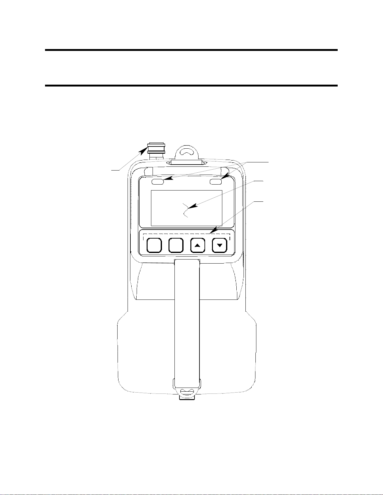
Chapter 2: Description
LCD Display
Control Buttons
Alarm LEDs
RANGE
SHIFT
DISPLAY
ADJUST
NO
AIR
YES
PO WER
ENTE R
RESET
Inlet Fitting
Overview
This chapter describes the EAGLE 2 instrument and accessories.
Instrument Description
The EAGLE 2 includes the case, sensors, LCD, control buttons, printed circuit boards,
alarm LEDs, infrared communication port, buzzer, battery case and batteries, and flow
system.
Figure 1: Component Location, Top View
14 • Overview EAGLE 2 Operator’s Manual
Page 15
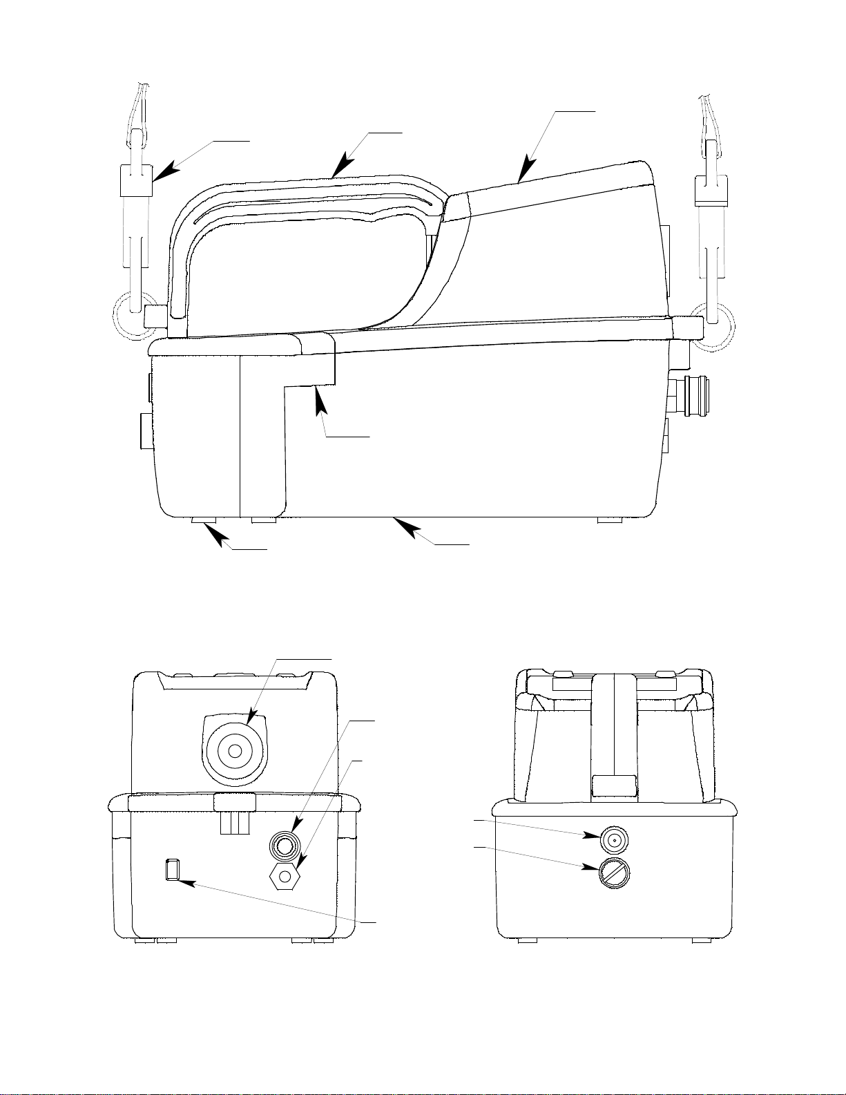
Top Case
Bottom Case
Strap
Case Foot, 6X
Handle
Case Screw, 3X
(Hidden From view)
Buzzer
Inlet Fitting
Exhaust Fitting
Battery Case
Thumbscrew
Charging Jack
Infrared Port
Figure 2: Component Location, Side View
Figure 3: Component Location, Front & Back
EAGLE 2 Operator’s Manual Instrument Description • 15
Page 16

Case
The EAGLE 2’s sturdy, high-impact plastic case is radio frequency (RF) resistant and is
suitable for use in many environmental conditions, indoors and out. The case is dust proof
and water resistant. It’s two main components, the top case and bottom case, are held
together with three screws located on the bottom case. The interface between the top case
and bottom case is gasketed. A sturdy, well balanced handle on the top case allows you to
hold the instrument comfortably. A clear plastic window is located on the top case to the
front of the handle for viewing the LCD.
A removable battery case is located at the rear of the bottom case. A thumbscrew secures
the battery case to the bottom case. The interface between the battery case and the bottom
case is gasketed. Six raised feet on the bottom of the case, four on the bottom case and two
on the battery compartment, raise the EAGLE 2 slightly from the surface on which it rests.
Sensors
The EAGLE 2 uses up to six sensors to monitor combustible gas, oxygen (O2), carbon
monoxide (CO), hydrogen sulfide (H2S), and various other toxic gases simultaneously.
The sensors are located inside the EAGLE 2 bottom case and are installed in the flow
chamber. The sensors described below are the four standard sensors. See “Appendix D:
PID Sensors” for a description of the PID sensors, “Appendix E: ESM-01 Toxic Sensors”
for a description of the ESM-01 toxic sensors, “Appendix F: TC Sensors” for a description
of the TC sensors, “Appendix G: Infrared Carbon Dioxide Sensors” for a description of
the IR CO2 sensors, “Appendix H: Infrared Methane Sensor” for a description of the IR
methane sensors, and “Appendix I: Infrared Hydrocarbon Sensor” for a description of the
IR hydrocarbon sensor. The standard sensors use different detection principles as
described below.
Catalytic Combustible Gas Sensor (LEL Sensor)
The catalytic combustible gas (LEL) sensor detects combustible gas in the %LEL range. It
uses a catalytic element for detection. The reaction of gas with oxygen on the catalyst
causes a change in the resistance of the element which changes the current flowing
through it. The current is amplified by the EAGLE 2’s circuitry, converted to a
measurement of combustible gas concentration, and displayed on the LCD.
The LEL sensor housing includes a sintered metal flame arrestor on one end that allows
gas to diffuse into the sensor. On the other end, five pins extend from the sensor. The
sensor cable connects to these pins on one end and terminates in a four-position connector
on the other end which plugs into the HC socket on the main PCB (see “Main PCB” on
page 19).
Oxygen Sensor
The O2 sensor is a galvanic type of sensor. A membrane behind the openings on the sensor
face allows gas to diffuse into the sensor at a rate proportional to the partial pressure of
oxygen. The oxygen reacts in the sensor and produces a voltage proportional to the
concentration of oxygen. The voltage is measured by the EAGLE 2’s circuitry, converted
to a measurement of gas concentration, and displayed on the LCD.
The sensor includes a short cable that terminates in a round 7-position connector. It mates
with the OXY pins on the main PCB (see “Main PCB” on page 19).
16 • Instrument Description EAGLE 2 Operator’s Manual
Page 17

CO and H2S Sensors
The CO and H2S sensors are electrochemical sensors that consist of three precious metal
electrodes in a dilute acid electrolyte. A gas permeable membrane covers the sensor face
and allows gas to diffuse into the electrolyte. The gas reacts in the sensor and produces a
current proportional to the concentration of the target gas. The current is amplified by the
EAGLE 2’s circuitry, converted to a measurement of gas concentration, and displayed on
the LCD.
The CO and H
S sensors are physically very similar. Except for their markings and wire
2
colors, they look almost identical. A three-position connector at the end of a 2-wire cable
from each sensor plugs into a socket on the main PCB. The sockets on the main PCB for
the CO and H
S sensors are labeled CO and H2S. Normally, the CO connector plugs into
2
the CO socket and the H2S plugs into the H2S socket. However, because of the way that
the main PCB circuitry is arranged, if the CO sensor is plugged into the H2S socket and
the H2S sensor is plugged into the CO socket, the sensors will still operate properly and
the CO and H2S readings will still appear on the channels that are programmed for those
gases.
LCD
A digital LCD (liquid crystal display) is visible through a clear plastic window in the top
case. The LCD simultaneously shows the gas reading for all installed sensors. The LCD
also shows information for each of the EAGLE 2’s operating modes.
Control Buttons
Four control buttons are located below the LCD. They are, from left to right, POWER
ENTER RESET, DISPLAY ADJUST NO, AIR
Table 3: EAGLE 2 Control Button Functions
Button Function(s)
POWER ENTER
RESET
• turns the EAGLE 2 on and off
• silences and resets audible alarm if Alarm Latching is set to
Latching and Alarm Silence is set to ON
• enters instructions, values, and settings into the EAGLE 2’s
microprocessor
▲ YES, and RANGE ▼ SHIFT.
DISPLAY ADJUST NO• activates Display Mode
• silences and resets audible alarm if Alarm Latching is set to
Latching and Alarm Silence is set to ON
• enters instructions into the EAGLE 2’s microprocessor
AIR ▲ YES • activates the demand zero function (adjusts the EAGLE 2’s
fresh air reading)
• silences and resets audible alarm if Alarm Latching is set to
Latching and Alarm Silence is set to ON
• enters instructions into the EAGLE 2’s microprocessor
• moves the cursor on the LCD up the screen
• increases the value of a parameter available for adjustment
• scrolls through parameter options
EAGLE 2 Operator’s Manual Instrument Description • 17
Page 18
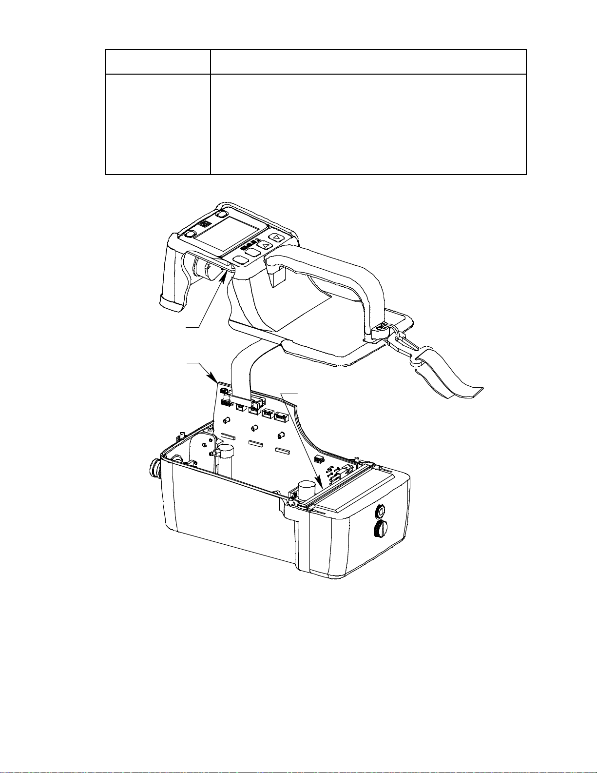
Table 3: EAGLE 2 Control Button Functions
Main PCB
Display PCB
I.S. B arri er PCB (not visble)
Button Function(s)
RANGE ▼ SHIFT • changes the detection units of the combustible gas channel
(when Catalytic Units is set to CHANGE OK in Setup Mode)
• silences and resets audible alarm if Alarm Latching is set to
Latching and Alarm Silence is set to ON
• enters instructions into the EAGLE 2’s microprocessor
• moves the cursor on the LCD down the screen
• decreases the value of a parameter available for adjustment
• scrolls through parameter options
Printed Circuit Boards (PCBs)
Figure 4: EAGLE 2 PCBs
The EAGLE 2’s PCBs analyze, record, control, store, and display the information
collected. The main PCB and I.S. barrier PCB are located in the bottom case. The display
PCB is located in the top case. The display PCB and I.S. barrier PCB are not user
serviceable and are not involved in any user performed maintenance. The main PCB is not
user serviceable, but it is involved in the replacement of sensors, so it is described below.
18 • Instrument Description EAGLE 2 Operator’s Manual
Page 19
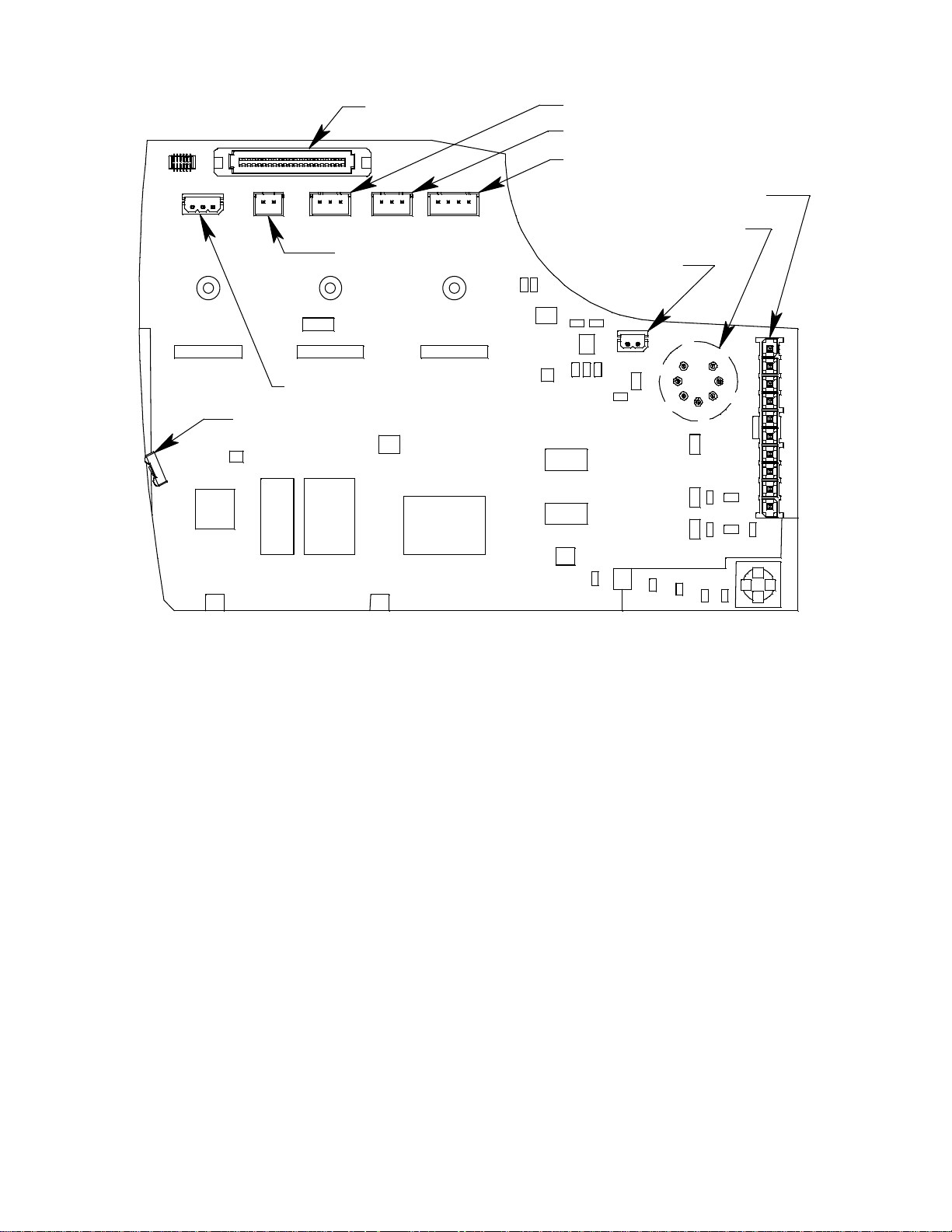
Figure 5: Main PCB
Oxygen Connector Pins (OXY)
I.S. Barrier Conn ector
LEL Connector (HC)
CO Connector (CO)
H2S Connector (H2S)
Pump Connecto r
FloatProbeConnector
Display connector
IR Communication Sensor /Transmitter
DP Switch Connector
The main PCB is located on the right side of the bottom case. It slides into guiding
grooves at the bottom, front, and rear of the bottom case. It is held in place by the top case.
Connectors for the sensors, differential pressure switch, pump, display PCB, optional float
probe, and I.S. barrier PCB are located on the main PCB. In addition, an IR transmitter/
receiver is located at the front of the PCB behind the IR port on the front of the bottom
case.
Alarm LEDs
Two sets of red alarm LEDs (light emitting diodes) are visible through two raised, frosted
plastic lenses in the top case. Each set has two LEDs. They are above the LCD, one above
the left corner and one above the right corner. The alarm LEDs alert you to gas, low
battery, and failure alarms.
Infrared Communications Port
An infrared (IR) communications port is located on the left front of the bottom case when
the instrument is viewed from the front. The data transmitted through the port is in
standard IrDA protocol. A computer’s infrared port or an IrDA/USB cable connected to a
USB port can be used to download data saved by the EAGLE 2 to a computer using the
Eagle 2 Data Logger Management Program. See the Data Logger Management Program
operator’s manual for data logging and downloading instructions.
EAGLE 2 Operator’s Manual Instrument Description • 19
Page 20

Buzzer
A solid-state electronic buzzer is located on the front of the top case. It is a panel mounting
type of buzzer and is water resistant and sealed to the inside of the top case with an O-ring.
The buzzer sounds for gas alarms, malfunctions, low battery voltage, and as an indicator
during use of the EAGLE 2’s many display and adjustment options.
Battery Case & Batteries
Four C-size alkaline batteries (standard) or optional rechargeable
C-size Ni-MH batteries power the EAGLE 2. They are installed in the battery case which
is located at the rear of the bottom case. The battery case is secured to the bottom case
with a thumbscrew.
Instrument run time is dependent upon battery type. At 25°C, alkaline batteries power the
EAGLE 2 for 16 hours of non-alarm operation. Ni-MH batteries will power the EAGLE 2
for 18 hours of non-alarm operation. The current battery voltage is viewable in Display
Mode (see “Display Mode” on page 41).
When the EAGLE 2 detects low battery voltage, a low battery warning is activated. When
battery voltage is too low for operation, the EAGLE 2 sounds a dead battery alarm.
The alkaline or Ni-MH batteries can be accessed for replacement by unscrewing the
thumbscrew that secures the battery case to the bottom case and pulling the battery case
away from the bottom case. The Ni-MH batteries can be recharged by using the EAGLE 2
charger (see “Replacing or Recharging the Batteries” on page 69).
NOTE: Use of batteries or battery chargers not specified by RKI Instruments, Inc. will
void the CSA classification and may void the warranty.
WARNING: To prevent ignition of a hazardous atmosphere, batteries must only be
changed or charged in an area known to be nonhazardous.
Flow System
The EAGLE 2 flow system consists of the inlet fitting, hydrophobic filter, pump, internal
tubing, differential pressure (DP) switch, sensor chamber, charcoal filter, and exhaust
fitting.
Inlet Fitting
The inlet fitting is on the right front (when viewed from the front) of the bottom case. It is
a nickel plated brass quick connect fitting. It mates with either the sample hose or with the
hydrophobic probe.
Hydrophobic Filter
The hydrophobic filter is located in the bottom case above the sensors. Normally the
hydrophobic probe accessory (see “Hose and Probe” on page 21) will prevent water and
particulate contamination from entering the flow system, but if the probe is not used, the
hydrophobic filter will stop water and particulates from penetrating further into the flow
system. If it becomes dirty or water logged, replace it (see “Replacing the Hydrophobic
Filter” on page 73).
Pump
A diaphragm pump inside the rear of the bottom case draws the sample to the sensors. It
can draw sample from as far as 125 feet from the EAGLE 2.
CAUTION: Sample hose lengths of more than 125 feet are not recommended for the
20 • Instrument Description EAGLE 2 Operator’s Manual
Page 21

EAGLE 2 because of flow rate reduction and increased response time.
Consult RKI Instruments, Inc. for sample hose lengths longer than 125 feet.
Internal Tubing
The flow system includes polyurethane tubing to route the sample between the various
components of the flow system. The internal sample tubing is not user serviceable.
Differential Pressure (DP) Switch
The DP switch is inside the front of the bottom case. It senses the EAGLE 2’s flowrate by
monitoring the pressure drop between points in the flow system. When the flowrate
becomes too low for safe operation of the EAGLE 2, a set of contacts inside it open and
the EAGLE 2 indicates a low flow alarm.
Sensor Chamber
A PVC block in the bottom case is configured to accept the four gas sensors. It routes the
sample to each sensor. The LEL sensor and the oxygen sensor are retained in the sensor
chamber by brackets. The CO and H2S sensors are each pushed past two sealing O-rings
into the chamber and are retained by the O-ring compression force.
Charcoal Filter
The charcoal filter is located in the front of the flow chamber next to the CO sensor. It
contains activated charcoal. The CO sensor will respond if exposed to H2S and certain
hydrocarbon gases. The charcoal filter scrubs these gases out of the sample to avoid false
CO readings. If false or elevated CO readings are noticed, especially in the presence of
S, change the charcoal filter. The charcoal inside the filter cannot be replaced; the entire
H
2
filter must be replaced.
Exhaust Fitting
The exhaust fitting is located below the inlet fitting. It routes the gas sample out of the
EAGLE 2. It includes a female 10-32 thread that can be used for the installation of a hose
barb or other type of fitting that has a male 10-32 thread so that the exhaust can be routed
to a particular location with flexible tubing if desired.
Standard Accessories
Standard accessories include the shoulder strap, the sample hose, and the hydrophobic
probe.
Shoulder Strap
A comfortable elastic shoulder strap clips to the EAGLE 2 at the front and rear of the top
case. It clips to stainless steel rings that are installed in features on the top case. It can be
removed from the EAGLE 2 by opening the clip at each end of the strap and removing it
from the strap ring at the front and rear of the top case.
Hose and Probe
A 5 foot polyurethane sample hose and a 10 inch hydrophobic probe are included as
standard. The hose has a male quick connect fitting on one end and a female quick connect
fitting on the other end. The probe has a male quick connect fitting. Normally, the male
end of sample hose is installed in the EAGLE 2 inlet fitting and the probe is installed in
the female end of the hose. However, if the sample hose is not needed for monitoring a
particular area, the probe may be installed directly to the inlet fitting. Sample hose lengths
EAGLE 2 Operator’s Manual Standard Accessories • 21
Page 22
are available from 5 feet (standard length) to 125 feet (see “General Parts List” on
Sample Hose
Probe
page 79). A Teflon lined hose is provided with all units that contain a PID sensor. This
hose must be used when operating a PID EAGLE 2 (see “Appendix D: PID Sensors” on
page 125).
CAUTION: Sample hose lengths of more than 125 feet are not recommended for the
EAGLE 2 because of flow rate reduction and increased response time.
Consult RKI Instruments, Inc. for hose lengths longer than 125 feet.
The probe includes a replaceable particle filter and hydrophobic filter disk that prevent
particulates and water from entering the EAGLE 2’s flow system. See “Replacing the
Hydrophobic Probe’s Particle Filter and Hydrophobic Filter Disk” on page 72 for
instructions to replace the particle filter and hydrophobic filter disk.
NOTE: When using the probe with a PID EAGLE 2, be sure that the particle filter is not
installed.
Figure 6: Sample Hose and Hydrophobic Probe
22 • Standard Accessories EAGLE 2 Operator’s Manual
Page 23
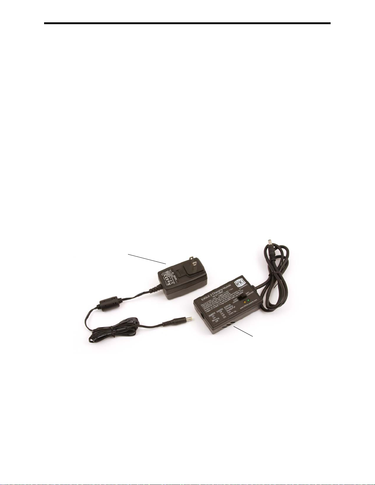
Optional Accessories
AC Adapter
Charging Module
Several optional accessories are available for the EAGLE 2. They include rechargeable
Ni-MH batteries, battery chargers, various special probes, and dilution fittings. The most
commonly used optional accessories are described below. Detailed instructions regarding
the use of these and other available accessories are included in other parts of this manual.
Data logging accessories are briefly described in “Data Logging” on page 52.
Rechargeable Ni-MH Batteries
Rechargeable Ni-MH batteries are available for the EAGLE 2. A fully charged set of NiMH batteries will power the EAGLE 2 for 18 hours. The batteries will last for a minimum
of 500 charge cycles. See “General Parts List” on page 79 for ordering information.
Battery Chargers
Three battery chargers are available for the EAGLE 2 to charge the optional Ni-MH
batteries, the standard AC charger, a DC charger with a vehicle plug adapter, and an AC/
DC charger with a vehicle plug adapter.
AC Charger
The standard AC charger consists of the charging module, which includes all of the
charging circuitry, and an AC adapter. The charging module includes a five foot cable with
a connector on the end that mates with the EAGLE 2 charging socket. The AC adapter
plugs into a 115 VAC wall outlet and connects to the charging module with a jack on the
end of a five foot DC output cable. The AC adapter will also work for 100 VAC or 220
VAC if an appropriate plug adapter is provided. The AC charging station is shown below
in Figure 7.
Figure 7: EAGLE 2 AC Charger
EAGLE 2 Operator’s Manual Optional Accessories • 23
Page 24
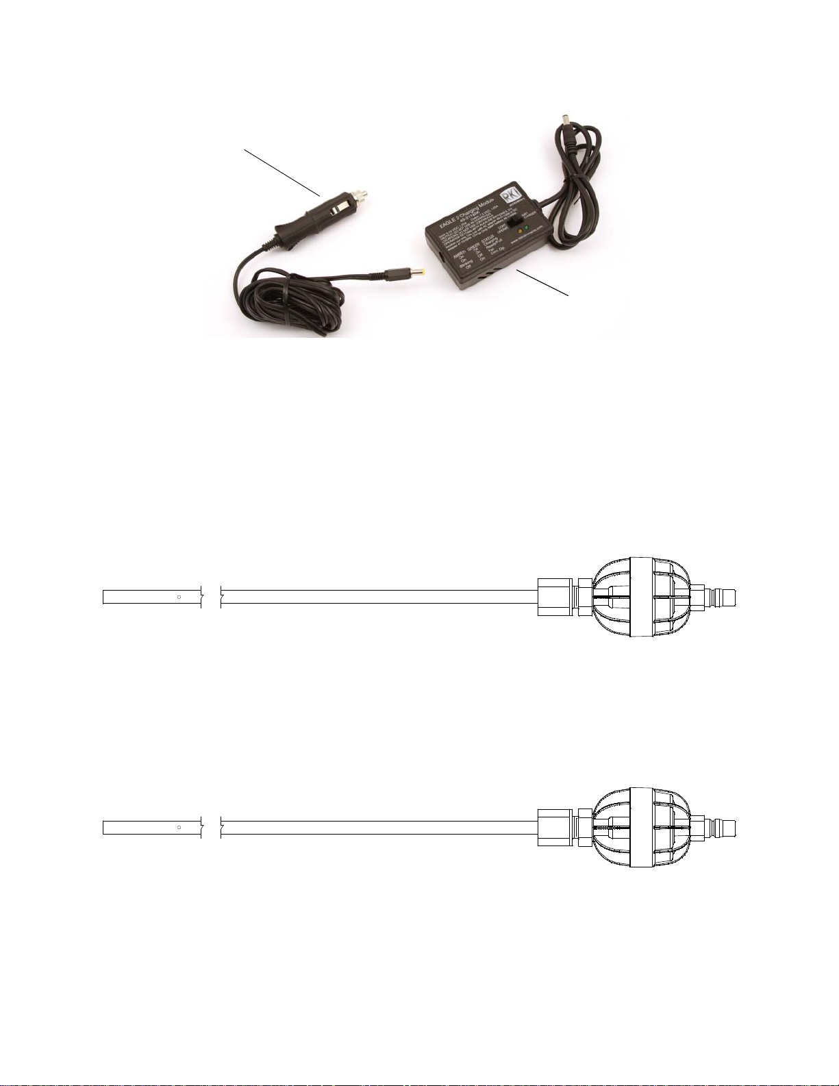
DC Charger
Vehicle Plug
DC Adapter
Charging Module
An optional DC powered charger is available with a vehicle plug 12 VDC adapter. It uses
the same charging module as the standard AC charger.
Figure 8: EAGLE 2 DC Charger
AC/DC Charger
A charger is also available that includes both the AC adapter and the 12 VDC vehicle plug
adapter. The charging module is the same as the one used for the AC charger and the DC
charger.
Optional Probes
Various optional probes designed for specific applications are available for the EAGLE 2.
They include the following:
• 30 inch aluminum probe
Figure 9: 30 Inch Aluminum Probe
This probe is designed for applications where it is necessary to put the probe tip in
areas that are out of reach with the standard probe. A small breather hole near the end
of the probe tube prevents interruption of sampling and a low flow alarm if the probe
tip is blocked.
• 30 inch stainless steel probe
24 • Optional Accessories EAGLE 2 Operator’s Manual
Figure 10: 30 Inch Stainless Steel Probe
This probe is physically the same as the 30 inch aluminum probe and is intended for
applications where a high level of corrosion resistance is required in the long probe
tube.
Page 25
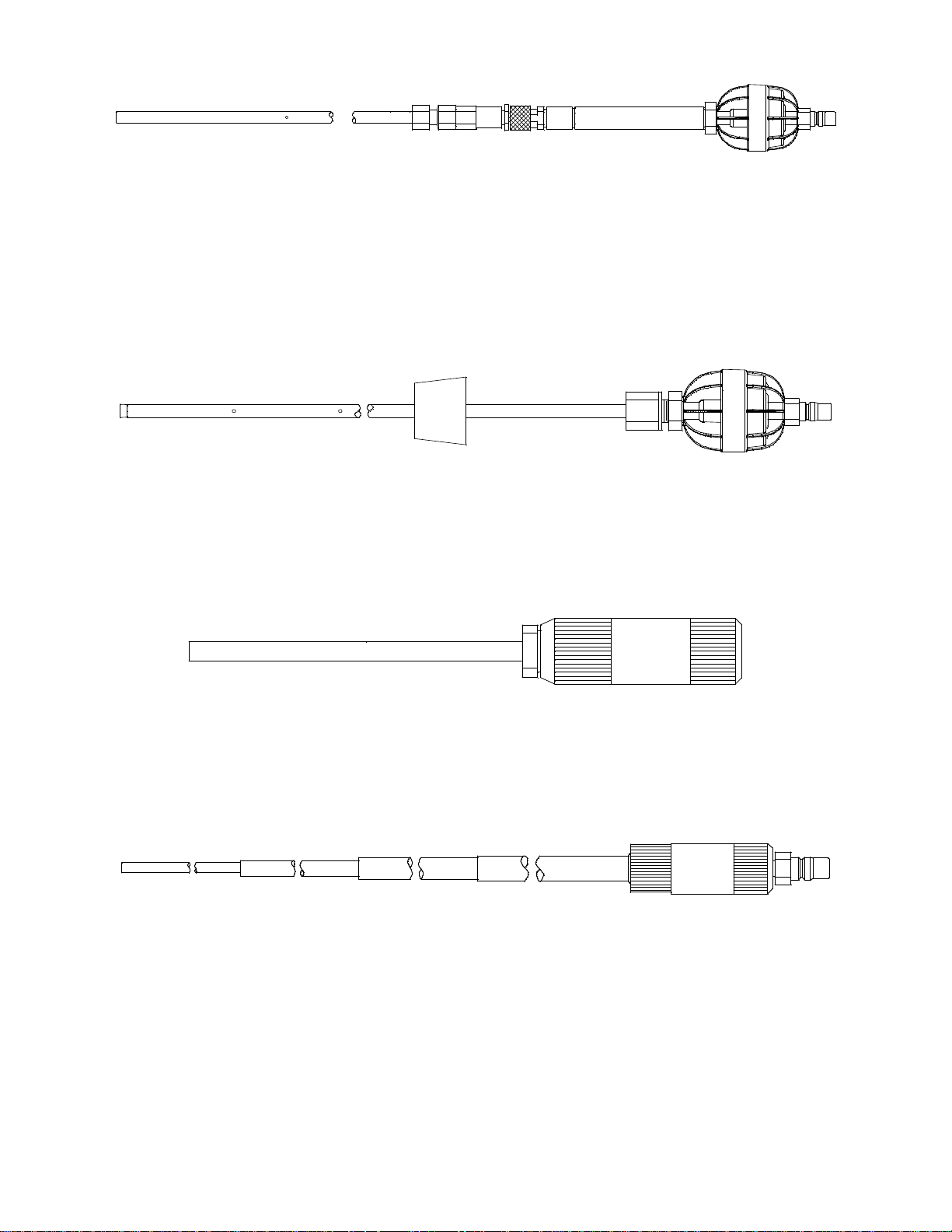
• 4 foot stainless steel probe
Figure 11: 4 Foot Stainless Steel Probe
This probe is designed for areas where it is necessary to put the probe tip in areas that
are out of reach for even the 30 inch probes. A stainless steel probe tube is used
because the length of the probe tube requires a high degree of rigidity. Stainless steel is
more rigid than other normally used materials. A small breather hole near the end of
the probe tube prevents interruption of sampling and a low flow alarm if the probe tip
is blocked.
• Barhole probe
Figure 12: Barhole Probe
This probe is designed specifically for barhole testing. See “Appendix K: Using the
EAGLE 2 in Bar Hole Mode” for an in-depth discussion of using the EAGLE 2 in Bar
Hole Mode.
• 10 inch probe with dust filter
Figure 13: 10 Inch Probe With Dust Filter
This probe is designed for use where drawing water or moisture into the EAGLE 2 is
not a concern. Instead of a hydrophobic filter, a cotton dust filter is used.
• 32 inch telescoping probe with dust filter
Figure 14: 32 Inch Telescoping Probe with Dust Filter
This probe is designed for use where it is necessary to put the probe tip in areas not
accessible with the 10 inch probe with dust filter and applications where the probe tube
must be collapsible for storage.
EAGLE 2 Operator’s Manual Optional Accessories • 25
Page 26
• 7 foot telescoping probe with dust filter
1:1 Diluti on Fitti ng
3:1 Dilution Fitting
Figure 15: 7 Foot Telescoping Probe with Dust Filter
This probe is designed for use where it is necessary to put the probe tip in areas not
accessible with the 32 inch telescoping probe with dust filter and applications where
the probe tube must be collapsible for storage.
See “General Parts List” on page 79 for probe ordering information.
External Dilution Fittings
Two external dilution fittings are available for the EAGLE 2, a 1:1 dilution fitting and a
3:1 dilution fitting. They are designed to mate with the inlet fitting and accept a sample
hose or probe. The fittings are made with brass and nickel plated brass and are appropriate
for use with the four standard gases. The 1:1 fitting is normally used when it is necessary
to introduce air into a sample that has no oxygen or a very low level of oxygen, such as a
nitrogen purged sample. Both the 1:1 and 3:1 fittings can also be used when one of the
target gas levels in the sample area will likely be present in a concentration above the
detection range for that gas. Since the fittings partially consist of unplated brass, they are
not appropriate for detection of elevated levels of H2S or of gases that are easily absorbed
such as Cl2 or SO2.
Figure 16: 1:1 and 3:1 Dilution Fittings
26 • Optional Accessories EAGLE 2 Operator’s Manual
Page 27

Chapter 3: Operation
GAS MONITOR
EAGLE 2
Overview
This chapter explains how to use the EAGLE 2 to perform confined space entry
monitoring or general area monitoring in Normal Mode. There are three operational
modes in Normal Mode: Measuring Mode, Display Mode, and Calibration Mode. While
in Normal Mode, the unit is normally operating in Measuring Mode. Display Mode and
Calibration Mode are accessible from Measuring Mode. Display Mode is described in this
chapter. Calibration Mode is described in “Chapter 4: Calibration Mode” on page 54.
Special versions of the EAGLE 2 can also operate in Leak Check Mode and Bar Hole
Mode. See “Appendix K: Using the EAGLE 2 in Bar Hole Mode” and “Appendix L:
Using the EAGLE 2 in Leak Check Mode” for operating instructions for Bar Hole and
Leak Check Mode, respectively.
Start Up
This section explains how to start up the EAGLE 2, get it ready for operation, and turn it
off.
NOTE: The screens illustrated in this section are for a standard 4-gas unit. The screens
displayed by your EAGLE 2 may be slightly different.
Turning On the EAGLE 2
To illustrate certain functions, the following description of the EAGLE 2 start up sequence
assumes that the following menu items in Setup Mode are turned on: LUNCH BREAK,
CAL REMINDER, and USER/STATION ID. If any of these items are turned off, then the
corresponding screens will not appear.
The EAGLE 2 may be used with a sample hose or with the probe installed directly to the
inlet fitting. Determine which configuration works best for your application.
1. Connect the sample hose or probe to the EAGLE 2’s quick connect inlet fitting.
2. If using a sample hose, connect the probe to the sample hose’s quick connect fitting.
3. Press and briefly hold down the POWER ENTER RESET button. Release the button
when you hear a beep.
4. The LCD will show the following screen for about ten seconds.
EAGLE 2 Operator’s Manual Overview • 27
Page 28

5. The Battery Voltage Screen appears for a few seconds.
BATTERY MIN:
4.3 VOLTS
BATTERY NOW:
5.2 VOLTS
ACTIVE GASES
CH4 OXY
H2S CO
LUNCH BREAK MODE ON
RESUME
PEAK AND TWA
MEASUREMENTS? 2
6. The Active Gases Screen appears for a few seconds indicating which channels are
active and their target gas.
7. If LUNCH BREAK is turned on (see “Updating the Lunch Break Setting” on
page 118), the Resume Measurement Screen appears. The unit counts down from 5
seconds in the lower right corner of the LCD to the right of “MEASUREMENTS”.
• To continue accumulating peak and time-weighted average (TWA) readings from
the last time the EAGLE 2 was used, press and release the AIR ▲ YES button
before the countdown reaches 0 or allow the countdown to reach 0. If you do not
press the AIR ▲ YES button within the 5 second countdown, the EAGLE 2
automatically resumes accumulating the peak and TWA readings.The EAGLE 2
will also continue to keep track of operating time including the operating time
from the last time the EAGLE 2 was used. See “Time in Operation Screen” on
page 50 for more information about how the EAGLE 2 tracks the operating time.
The short-term exposure limit (STEL) reading is reset each time the EAGLE 2 is
turned on.
• To reset the accumulation of these measurements, press and release the
DISPLAY ADJUST NO button before the countdown reaches 0.
28 • Start U p EAGLE 2 Operator’s Manual
Page 29

8. The gas alarm setpoints are displayed by three screens in sequence: the Low Alarm
A CH4 10 %LEL
L L OXY 19.5 vol%
O A H2S 10.0 ppm
WR CO 25 ppm
M
S
CH4 10 vol%
A CH4 50 %LEL
HL OXY 23.5 vol%
I A H2S 30.0 ppm
GR CO 50 ppm
HM
S
CH4 50 vol%
ALARMS STEL & TWA
H2S(ppm) 15.0 10.0
CO (ppm) 200 25
CALIBRATION DATE
IS PAST DUE
PERFORM
CALIBRATION?
Screen, High Alarm Screen, and STEL/TWA Alarm Screen. Each screen remains on
the LCD for three seconds.
9. After the alarm screens, if CAL REMINDER is turned on, the screen that appears
next depends on how CAL PAST DUE ACT is set in the Setup Mode Menu (see
“Updating the Calibration Past Due Action Setting” on page 113).
• If the unit is due for calibration and CAL PAST DUE ACT is set to CONFIRM
TO CAL, then the following screen displays and the buzzer sounds in a double
pulsing pattern.
To perform a calibration, press and release the AIR ▲ YES button. The EAGLE
2 will enter Calibration Mode and the LCD will show the Calibration Mode main
menu. See “Chapter 4: Calibration Mode” on page 54 for instructions to calibrate
the EAGLE 2. When you are done with the calibration and exit Calibration
Mode, the unit will begin the startup sequence. If the calibration was successful,
the screen above will not appear again until the unit is due for calibration. If the
calibration was not successful, the screen above will again appear in the startup
sequence.
To continue without performing a calibration, press and release the DISPLAY
ADJUST NO button.
EAGLE 2 Operator’s Manual Start Up • 29
Page 30

• If the unit is due for calibration and CAL PAST DUE ACT is set to MUST
CALIBRATION DATE
IS PAST DUE
ENTER TO PERFORM
CALIBRATION
CALIBRATION DATE
IS PAST DUE
9/12/2008
15:00:00
CALIBRATE, then the following screen displays and the buzzer sounds in a
double pulsing pattern.
The EAGLE 2 cannot be used until a successful calibration has been performed.
Press and release the ENTER button to enter Calibration Mode. See “Chapter 4:
Calibration Mode” on page 54 for instructions to calibrate the EAGLE 2.
NOTE: In this situation, even if the password function has been turned on, no password
is required to perform a calibration.
When you are done with the calibration and exit Calibration Mode, the unit will
begin the startup sequence. If the calibration was successful, the screen above
will not appear again until the unit is due for calibration. If the calibration was
not successful, the screen above will again appear in the startup sequence.
• If the unit is due for calibration and CAL PAST DUE ACT is set to
NOTIFICATION ONLY, then the following alert screen displays and the buzzer
sounds in a double pulsing pattern.
Press and release the POWER ENTER RESET button to acknowledge the alert
and continue with the startup sequence.
10. The Date/Time Screen appears for a few seconds.
30 • Start U p EAGLE 2 Operator’s Manual
Page 31

11. If USER/STATION ID is turned on (see “Turning the User/Station ID Function On or
USER ID
MIKE
STATION ID
PUMP 1
SERIAL NUMBER
E2A515
FAILED SENSOR(S)
< > < >
<H2S> < >
ENTER TO CONTINUE
CH4 0%LEL
OXY 20.9vol%
H2S 0.0ppm
CO 0ppm
Off” on page 109), the ID Screen appears for a few seconds.
If USER/STATION ID is turned off, only the serial number is shown.
12. If the EAGLE 2 experiences a sensor failure during start up, a screen indicating which
sensor failed appears and the buzzer sounds a pulsing tone twice per second. In the
example below, the H2S sensor has failed.
If you wish to continue, press and release the POWER ENTER RESET button to
acknowledge the failure. The gas reading for the failed sensor will be replaced by
“XXX”. Replace the failed sensor as soon as possible.
13. The EAGLE 2 is now monitoring for gas in Measuring Mode. The Normal Operation
Screen appears displaying the current gas reading for each target gas.
Performing a Demand Zero
Before using the EAGLE 2, it is recommended to set the fresh air readings for the target
gases by performing a demand zero. This will set the CH4, H2S, and CO channels to zero
and the OXY channel to 20.9%.
1. Find a fresh-air environment. This is an environment free of toxic or combustible
gases and of normal oxygen content (20.9%).
2. Turn on the unit as described above in “Turning On the EAGLE 2”.
3. Press and hold the AIR ▲ YES button. The LCD prompts you to continue holding the
AIR ▲ YES button and the buzzer will pulse while you hold the button.
4. Continue to hold the AIR ▲ YES button until the LCD prompts you to release it. The
EAGLE 2 will set the fresh air reading for all channels. Start up is complete and the
unit is now ready for monitoring.
EAGLE 2 Operator’s Manual Start Up • 31
Page 32

Turning Off the EAGLE 2
1. Press and hold the POWER ENTER RESET button.
2. The buzzer will pulse for about five seconds.
3. Release the button when GOODBYE and the RKI logo appear on the display. When
GOODBYE and the RKI logo disappear and the backlight turns off, the unit is off.
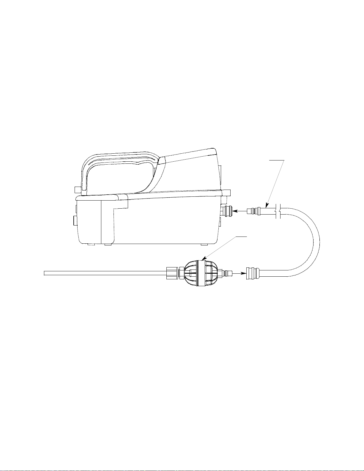
Using the Battery Charger for Continuous Operation
The battery charger can be used with an AC adapter or a vehicle plug DC adapter to run
the EAGLE 2 in continuous operation instead of charging the batteries. Batteries do not
need to be installed in the EAGLE 2 but if there are batteries installed, they must be NiMH
batteries and they must have a charge.
WARNING: Use the EAGLE 2 charger’s continuous operation mode to power the
EAGLE 2 only if NiMH batteries are installed in the EAGLE 2 or if no
batteries are installed in the EAGLE 2. Do not use the charger for
continuous operation if alkaline batteries are installed.
1. Place the EAGLE 2 in the area to be monitored.
2. Plug the power adapter into either an AC outlet or into a vehicle outlet depending on
which charger is being used.
3. Set the switch on the module to “CONT. OPERAT.”.
4. Make sure the EAGLE 2 is off.
5. Make sure the adapter and module are connected.
6. Make sure that the NiMH batteries are either charged or removed.
NOTE: If the batteries are not charged, the EAGLE 2 will not turn on and will instead
give a “Charge Batteries” indication when it is powered up after Step 7 below.
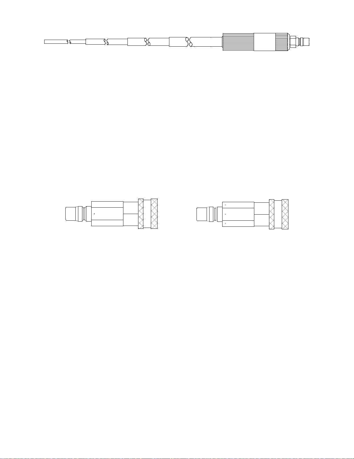
7. Insert the module’s round plug into the EAGLE 2’s charging jack as shown in Figure
17 below.
Figure 17: Connecting the EAGLE 2 to the Charger
32 • Using the Battery Charger for Continuous Operation EAGLE 2 Operator’s Man-
Page 33

8. See “Chapter 3: Operation” on page 27 for instructions for start-up and operation of
CH4 0%LEL
OXY 20.9vol%
H2S 0.0ppm
CO 0ppm
the EAGLE 2.
9. While the charging module is powering the EAGLE 2, its amber LED will be off and
its green LED will be on.
Measuring Mode, Normal Operation
When the EAGLE 2 completes its startup sequence, it is in Measuring Mode. In
Measuring Mode the EAGLE 2 continuously monitors the sampled atmosphere and
displays the gas concentrations present for its target gases. In a low-light environment,
press and release any button to turn on the display backlight. See “Updating the Backlight
Delay Setting” on page 110 to program backlight duration. If the Confirmation Alert
feature is turned on in the Setup Mode menu (see “Updating the Confirmation Alert
Setting” on page 115), the EAGLE 2 beeps periodically to confirm that it’s operating.
Monitoring an Area
1. Start up the EAGLE 2 as described above in “Start Up” on page 27. It is now in
Measuring Mode.
2. Take the EAGLE 2 to the monitoring area.
Put the probe tip in the area to be monitored.
NOTE: If the particle filter or hydrophobic filter become dirty or clogged, replace them.
If water enters the probe, dry out or replace the particle filter (if installed) and
shake any water out of the probe or off of the hydrophobic filter. If you notice
that water has entered the flow system through the probe, replace the probe’s
hydrophobic filter and inspect the O-ring for filter particles. See “Replacing the
Hydrophobic Probe’s Particle Filter and Hydrophobic Filter Disk” on page 72
for instructions to replace the particle filter and the hydrophobic filter.
3. Wait 10 - 15 seconds and observe the display for gas readings. If a reading is
observed, allow the reading to stabilize to determine the gas concentrations present.
NOTE: Response time increases with the length of the sample hose. Long sample hoses
will require more time to show a response at the EAGLE 2. The maximum
sample hose length recommended for the EAGLE 2 is 125 feet. Consult RKI
Instruments, Inc. for longer sample hose lengths.
4. If a gas alarm occurs, take appropriate action. See “Responding to Alarms” on
page 40.
EAGLE 2 Operator’s Manual Measuring Mode, Normal Operation • 33
Page 34

Using Optional Sample Hoses
The standard sample hose for the EAGLE 2 is 5 feet long. Optional hoses are available up
to 125 feet long. If you are considering using a longer hose, keep in mind that a longer
hose will increase the EAGLE 2’s response time and the flowrate may decrease close to
the low flow alarm point.
CAUTION: Sample hose lengths of more than 125 feet are not recommended for the
EAGLE 2 because of flow rate reduction and increased response time.
Consult RKI Instruments, Inc. for hose lengths longer than 125 feet.
The chart below illustrates how response time is affected by the sample hose length.
Table 4: EAGLE 2 Response Time vs. Sample Hose Length
Hose Used
Probe Only 12 seconds
Probe & 5 Foot Hose 15 seconds
Probe & 25 Foot Hose 25 seconds
Probe & 50 Foot Hose 35 seconds
Probe & 75 Foot Hose 45 seconds
Probe & 100 Foot Hose 60 seconds
Probe & 125 Foot Hose 75 seconds
Typical Time to 90%
of Response (T90)
Using Exhaust Tubing
The EAGLE 2’s exhaust fitting has a female 10-32 thread to allow for the installation of a
hose barb fitting with a 10-32 thread to which a flexible exhaust tube can be connected. If
you utilize this feature, the tubing used must have a minimum internal diameter of 1/8
inch. RKI Instruments, Inc. recommends using flexible polyurethane tubing with a
maximum exhaust tube length of 20 feet. Consult RKI Instruments, Inc. for exhaust tubing
lengths longer than 20 feet.
Combustible Gas Detection
There are three issues to keep in mind when monitoring for combustible gas.
• The catalytic combustible sensor will respond to any combustible gas. The standard
calibration gas for the EAGLE 2 catalytic combustible channel is methane (CH4). If
the instrument is calibrated to a different combustible gas, such as hexane or propane,
the gas name for the catalytic combustible channel will reflect the target gas.
The table below lists the conversion factors for several hydrocarbon gases if the
EAGLE 2 is calibrated to methane. To use this table, multiply the display reading on
the combustible gas channel by the factor in the appropriate row to obtain the actual
gas concentration. For example, if you are detecting pentane and the display reads 10%
LEL for the catalytic combustible channel, you actually have 10% LEL x 1.95 = 19.5%
LEL pentane present.
34 • Measuring Mode, Normal Operation EAGLE 2 Operator’s Manual
Page 35

Table 5: Full Response Mode Conversion Factors (Methane Calibration)
Target Gas LEL Factor PPM Factor Target Gas LEL Factor PPM Factor
Acetone 1.40 0.70 Isobutane 1.61 0.58
Benzene 1.75 0.42 Isopropanol 2.22 0.89
Butyl Acrylate 3.95 1.34 Methane 1.00 1.00
Butyl Acetate 3.38 0.88 Methanol 1.23 1.48
2-Butyl Alcohol 1.94 0.66 Methyl Acetate 1.37 0.85
1-Butyl Alcohol 2.65 0.74 Methyl Acrylate 1.10 0.62
Cyclohexane 1.82 0.47 Methyl Ethyl
Ketone
Cumene 3.90 0.70 Methyl Isobutyl
Ketone
Ethylene
Dichloride
Ethyl Alcohol 1.38 0.91 Nonane 2.87 0.46
Ethyl Chloride 1.26 0.96 Pentane 1.95 0.59
Ethyl Acrylate 2.45 0.69 Propane 1.50 0.63
Hexane 2.44 0.54 Styrene 2.94 0.53
Hydrogen 1.16 0.93 Toluene 2.16 0.48
2.75 3.41 Mixed Xylenes 2.36 0.52
Vinyl Acetate
Monomer
2.53 0.71
2.53 0.61
1.48 0.77
* Vapor pressure too low for significant LEL reading
• The EAGLE 2 provides the catalytic combustible sensor with some protection against
exposure to high levels of combustible gas which can damage the sensor. It does this
by turning off the combustible sensor power temporarily when it determines that an
over scale (more than 100% LEL) concentration of combustible gas is present that
may damage the sensor. Nevertheless, concentrations of combustible gas of more than
100% LEL can still affect the zero level or calibration of the combustible sensor if the
concentration is high enough.
CAUTION: Do not expose the catalytic combustible sensor to high concentrations of
combustible gas such as that from a butane lighter. Exposure to high
concentrations of combustible gas may adversely affect the performance of
the sensor.
CAUTION: Any rapid increase in the combustible gas reading on the catalytic
combustible channel followed by a declining or erratic reading may
indicate a gas concentration above the LEL which may be hazardous.
EAGLE 2 Operator’s Manual Measuring Mode, Normal Operation • 35
Page 36

• Some gases such as silicone vapors, chlorinated hydrocarbons, and sulphur
CH4 0%LEL
OXY 20.9vol%
H2S 0.0ppm
CO 0ppm
CH4 0.00vol%
OXY 20.9vol%
H2S 0.0ppm
CO 0ppm
RANGE
SHIFT
CH4 0ppm
OXY 20.9vol%
H2S 0.0ppm
CO 0ppm
RANGE
SHIFT
RANGE
SHIFT
compounds can contaminate the detection elements inside the combustible sensor
damaging the sensor and result in reduced response to combustible gas. Make every
effort to avoid these gases. The catalytic combustible sensor has an integral H2S
scrubber for protection from H2S exposure resulting from normal use, but you should
avoid exposure to high levels of H
S and other sulphur compounds.
2
Monitoring Combustible Gas in the PPM or %Volume Range
The standard factory configuration for the EAGLE 2 allows the user to use the RANGE ▼
SHIFT button to change the displayed detection units of the catalytic combustible channel
between %LEL, ppm, and %volume. It is possible to disable this capability and set the
EAGLE 2 to display only one of the detection units by using the Catalytic Units menu
item in Setup Mode. See “Setting the Catalytic Detection Units” on page 105 for
instructions to set this Setup Mode Menu item.
The detection range of the combustible catalytic channel when set for ppm or %volume
will correspond to 0 - 100% LEL for the configured gas. For example, the LEL for
methane (CH
displayed in terms of %volume, the full scale is 5.00% and if it is displayed in terms of
ppm, the full scale is 50,000 ppm.
If the Catalytic Units menu item in Setup Mode is set to CHANGE OK, the standard
factory setting, then you can change the catalytic combustible channel’s units by pressing
and releasing RANGE ▼ SHIFT.
) is 5% volume, or 50,000 ppm. So if the catalytic combustible channel is
4
36 • Measuring Mode, Normal Operation EAGLE 2 Operator’s Manual
Page 37

Monitoring Combustible Gas in the PPM Range
There are special considerations that must be taken into account when monitoring
combustible gas in the ppm range with the catalytic combustible channel. Because of the
high sensitivity in the lower part of the ppm range, the catalytic combustible channel
needs more time than the warm-up period to stabilize after the EAGLE 2 is turned on if it
is going to be used for ppm level detection. The reading increments in the ppm range are
smallest in the lower part of the range and increase as the reading increases as follows:
• 5 ppm increments from 0 ppm to 200 ppm
• 10 ppm increments from 200 ppm to 1,000 ppm
• 50 ppm increments from 1,000 ppm to 10,000 ppm
• 250 ppm increments from 10,000 ppm to 50,000 ppm
If the catalytic combustible channel is configured for the user defined gas in Setup Mode
(see “Configuring the Combustible Gas” on page 101), the ppm ratio defined for the gas
must be considered. For example, if the ppm ratio is set higher than 50,000 ppm, then
when the display units are set as ppm, the reading will not go above 50,000 ppm which is
equivalent to 33 % LEL and 5 %volume. So if the gas reading is higher than 50,000 ppm,
the ppm unit reading will indicate 50,000 ppm and also indicate an overscale condition.
The %LEL and %volume unit readings will still increase up to 100% LEL and 15
%volume respectively, which are equivalent to 150,000 ppm.
The catalytic combustible sensor is slightly affected by humidity. This is not apparent
when the EAGLE 2 is used for %LEL or %volume detection, but because of the high
sensitivity in the ppm range, significant humidity changes can affect the ppm reading,
especially in the lower part of the range. Take care to allow the unit to acclimate to a new
environment for about a minute and perform a demand zero in a fresh air location when
you move between areas of different humidity.
CAUTION: If the catalytic combustible channel is being calibrated with a gas
concentration of 1000 ppm or lower, the a 24 inch humidifier must be used
for accurate calibration. See “Chapter 4: Calibration Mode” on page 54
for more explanation and instructions for calibration.
To monitor for combustible gas in the ppm range:
1. Start up the EAGLE 2 as described in “Start Up” on page 27.
2. Allow the EAGLE 2 to run for 3 - 5 minutes after the startup sequence is complete
and it is in Measuring Mode. This allows the catalytic combustible sensor to stabilize
sufficiently for ppm monitoring.
NOTE: This extra stabilization period is not necessary if monitoring in the %LEL or
%volume range.
3. Set the catalytic combustible channel’s units to be ppm by using the RANGE ▼
SHIFT button.
4. Perform a demand zero as described in “Performing a Demand Zero” on page 31.
5. Proceed to monitor for gas as described in “Monitoring an Area” on page 33.
EAGLE 2 Operator’s Manual Measuring Mode, Normal Operation • 37
Page 38

Measuring Mode, Alarms
This section covers alarm indications in Measuring Mode. It also describes how to reset
the EAGLE 2 after an alarm has occurred and how to respond to an alarm condition.
NOTE: False alarms may be caused by radio frequency (RF) or electromagnetic (EMI)
interference. Keep the EAGLE 2 away from RF and EMI sources such as radio
transmitters or large motors.
Alarm Indications
The EAGLE 2 will sound an alarm and flash the LED arrays when one of the target gas
concentrations rises above the Low Alarm level, or in the case of oxygen falls below the
Low Alarm level, for that gas.
The EAGLE 2 also sounds an alarm and flashes the LED arrays when one of the target gas
concentrations rises above the High Alarm level and when the STEL and TWA alarm
levels are reached for CO and H2S.
NOTE: If an alarm condition occurs while you are in Display Mode, the EAGLE 2 will
automatically bring up the alarm screen instead.
When a failure condition occurs, such as a sensor failure, low flow, or dead battery
condition, the unit will also sound an alarm and flash the LED arrays.
The table below summarizes the types of alarms produced by the EAGLE 2 and their
indications.
Table 6: Alarm Types and Indications
Alarm Type Visual Indications Audible Indication
Low Alarm
Concentration of gas rises
above the Low Alarm setting
or falls below the Low Alarm
setting for O
.
2
High Alarm
Concentration of gas rises
above the High Alarm
setting.
TWA or STEL
Concentration of CO or H2S
rises above the TWA or
STEL alarm setting.
• ALRM1 appears next to gas
reading
• Alarm LED arrays flash once
per second
• Backlight turns on
• ALRM2 appears next to gas
reading
• Alarm LED arrays flash twice
per second
• Backlight turns on
• Alarm LED arrays flash once
per second
• Backlight turns on
• TWA or STEL appears next to
gas reading
Pulsing tone once per
second
Pulsing tone twice per
second
Pulsing tone once per
second
38 • Measuring Mode, Alarms EAGLE 2 Operator’s Manual
Page 39

Table 6: Alarm Types and Indications
Alarm Type Visual Indications Audible Indication
Over Range
Low Flow
Low Battery Warning
Dead Battery Alarm
Sensor Failure
• OVER appears next to gas
reading
• Gas reading indicates full
scale
• Alarm LED arrays flash twice
per second
• Backlight turns on
• The display indicates FAIL
LOW FLOW LEVEL
• Alarm LED arrays flash in a
double pulsing pattern once
per second
• Backlight turns on
• BATT appears vertically along
the left side of LCD
• Gas readings replaced by
RECHARGE INSTRUMENT
BATTERIES
• Alarm LED arrays flash in a
double pulsing pattern once
per second
• FAILED SENSOR(S) appears
at the top of the display and
the failed sensor(s) are
indicated
• Alarm LED arrays flash in a
double pulsing pattern once
per second
Pulsing tone twice per
second
Double pulsing tone
once per second
None
Double pulsing tone
once per second
Double pulsing tone
once per second
Resetting and Silencing Alarms
You can set the EAGLE 2’s gas alarms as latching or self-resetting alarms (see “Updating
the Alarm Latching Setting” on page 108).
• Self-resetting alarms (ALARM LATCHING set to SELF RESET)
Self-resetting alarms automatically shut off and reset when the gas reading falls below
(or rises above for an oxygen low alarm) the alarm setting. You cannot reset selfresetting alarms with the POWER ENTER RESET button. You can set self-resetting
alarms with or without the alarm silence feature (see “Updating the Alarm Silence
Setting” on page 108).
• Latching alarms (ALARM LATCHING set to LATCHING)
Latching alarms will remain in effect until the gas reading falls below (or rises above
for an oxygen low alarm) the alarm setting and they are reset with the POWER
ENTER RESET button. You can set latching alarms with or without the alarm silence
feature (see “Updating the Alarm Silence Setting” on page 108).
EAGLE 2 Operator’s Manual Measuring Mode, Alarms • 39
Page 40

ALARM SILENCE On and Alarms Set to LATCHING:
ALARM SILENCE set to ON and ALARM LATCHING set to LATCHING are the
factory settings. When the EAGLE 2 goes into gas alarm, press and release any button to
silence the buzzer. If the gas concentration was still above the alarm level when the button
was pressed, the LED arrays continue to flash, and the EAGLE 2 continues to display the
current alarm level.
The gas reading must fall below (or rise above for an oxygen low alarm) an alarm setting
before you can reset the alarm. When the alarm condition passes, press and release the
POWER ENTER RESET button to reset the alarm. The LED arrays turn off and the
EAGLE 2 alarm indications on the display turn off.
ALARM SILENCE Off and Alarms Set to LATCHING:
The gas reading must fall below (or rise above for an oxygen low alarm) an alarm setting
before you can reset the alarm. When the alarm condition passes, press and release the
POWER ENTER RESET button to reset the alarm. The LED arrays and buzzer turn off
and the EAGLE 2 alarm indications on the display turn off.
ALARM SILENCE On and Alarms Set to SELF RESETTING:
When the EAGLE 2 goes into gas alarm, press and release any button to silence the
buzzer. The POWER ENTER RESET button will not reset the alarm. When the gas
reading falls below (or rises above for an oxygen low alarm) an alarm setpoint, the alarm
will automatically reset. The LED arrays turn off and the EAGLE 2 alarm indications on
the display turn off.
With ALARM SILENCE Off and Alarms Set to SELF RESETTING:
When the EAGLE 2 goes into gas alarm, the POWER ENTER RESET button will not
silence or reset the alarm. When the gas reading falls below (or rises above for an oxygen
low alarm) an alarm setpoint, the alarm will automatically reset. The LED arrays and
buzzer turn off and the EAGLE 2 alarm indications on the display turn off.
Responding to Alarms
This section describes response to gas, over range, battery, and sensor failure alarms.
Responding to Gas Alarms
1. Determine which gas alarm has been activated.
2. Follow your established procedure for an increasing gas condition or a decreasing
oxygen condition.
3. If necessary, reset the alarm using the POWER ENTER RESET button once the alarm
condition has passed.
Responding to Over Range Alarms
WARNING: An over range condition may indicate an extreme combustible gas,
toxic gas, or oxygen concentration. Confirm a normal condition with a
different EAGLE 2 or with another gas detecting device.
1. Determine which channel is in alarm.
2. Follow your established procedure for an extreme gas condition.
3. Reset the alarm using the POWER ENTER RESET button once the alarm condition
has cleared.
4. Calibrate the EAGLE 2 as described in “Chapter 4: Calibration Mode” on page 54.
40 • Measuring Mode, Alarms EAGLE 2 Operator’s Manual
Page 41

5. If the over range condition continues or if you are not able to successfully calibrate
the unit, you may need to replace the sensor that has triggered the over range alarm.
6. If the over range condition continues after you have replaced the sensor, contact RKI
Instruments, Inc. for further instructions.
Responding to Battery Alarms
WARNING: The EAGLE 2 is not operational as a gas monitoring device during a
dead battery alarm. Take the Model EAGLE 2 to a non-hazardous area
and replace or recharge the batteries as described in “Replacing or
Recharging the Batteries” on page 69.
The EAGLE 2 is fully functional during a low battery warning. However, only a limited
amount of operating time remains, approximately 1 - 2 hours. The amount of time depends
on how often the LCD backlight is used and how often the unit is responding to alarm
conditions. Recharge the Ni-MH batteries or replace the alkaline batteries as soon as
possible as described in “Replacing or Recharging the Batteries” on page 69.
NOTE: Alarms and the LCD back light consume battery power and reduce the amount
of operating time remaining.
Responding to Sensor Failure Alarms
1. Determine which sensor has triggered the sensor failure alarm.
2. Try calibrating the sensor first, as described in “Chapter 4: Calibration Mode” on
page 54 before replacing it.
3. If the sensor failure continues, replace the sensor as described in “Replacing a
Sensor” on page 76.
4. If the sensor failure condition continues after you have replaced the sensor, contact
RKI Instruments, Inc. for further instructions.
Display Mode
Two other operating modes are accessible when the EAGLE 2 is in Measuring Mode.
They are Display Mode and Calibration Mode. This section describes using the EAGLE 2
in Display Mode. In Display Mode you can:
• display peak readings
• display the minimum operating and current battery voltage
• select how the active channels are displayed on the LCD
• turn the catalytic LEL sensor on or off (if there is a TC or infrared combustible channel
along with a catalytic combustible channel)
• enable or disable methane elimination mode (if the catalytic combustible gas channel
is configured appropriately in the CONFIGURE GASES item in Setup Mode)
• temporarily configure the catalytic combustible channel for a target gas other than the
one used for calibration (if the RELATIVE RESPONSE item in Setup Mode is set to
ON)
• display STEL readings (H
• display TWA readings (H2S and CO only)
EAGLE 2 Operator’s Manual Display Mode • 41
S and CO only)
2
Page 42

• display alarm settings
CH4 0%LEL
P OXY 20.9vol%
E H2S 0.0ppm
A CO 0ppm
K
CLEAR
PEAK READINGS?
• select the user ID (if the USER/STATION ID item in Setup Mode is set to ON)
• select the station ID (if the USER/STATION ID item in Setup Mode is set to ON)
• display time in operation
• display date and time
• display remaining data logging time and clear data logger memory (if the DATA LOG
MEMORY item in Setup Mode is set to ON)
Tips for Using Display Mode
• To enter Display Mode and scroll from one screen to the next or skip an item when a
question is asked, press and release the DISPLAY ADJUST NO button.
• To enter an item when a question is asked, press and release the AIR ▲ YES button.
• To change a flashing parameter, use either the AIR ▲ YES button or RANGE ▼
SHIFT button.
NOTE: Each screen displays for 20 seconds. If you do not press a button within 20
seconds, the EAGLE 2 automatically returns to Measuring Mode.
Peak Screen
The peak screen displays the highest (lowest for oxygen) concentrations detected since the
EAGLE 2 was turned on. Peak readings are stored in the EAGLE 2’s memory until a
higher level is detected (lower for oxygen), the peak reading is cleared, or the EAGLE 2 is
turned off.
The lunch break feature enables the EAGLE 2 to save peak readings when it is turned off
so it can continue them when it is turned on again. See “Turning On the EAGLE 2” on
page 27
To clear the peak readings, do the following:
1. With the Peak Screen displayed, press and release the POWER ENTER RESET
button. The following screen will appear.
2. Press and release the AIR ▲ YES button. The peak readings will be reset and the unit
will return to the Peak Screen.
42 • Display Mode EAGLE 2 Operator’s Manual
Page 43

If you do not want to clear the peak readings, press and release the DISPLAY
BATTERY MIN:
4.3 VOLTS
BATTERY NOW:
5.2 VOLTS
SELECT
GASES DISPLAYED
SELECT
> DISPLAY ALL
SCROLL AUTO
SCROLL MANUAL
ADJUST NO button and the unit will return to the Peak Screen without clearing the
peak readings.
Battery Voltage Screen
The Battery Voltage Screen displays the minimum operating voltage and the current
battery voltage. Fully charged alkaline batteries typically indicate 6.0 volts; fully charged
Ni-MH batteries typically indicate 5.2 volts. This screen also displays during the startup
sequence.
Gas Display Screen
The Gas Display Screen gives you the option to select how the active channels are
displayed.
You can display all of them on the screen at the same time, one at a time with automatic
scrolling, or one at time with manual scrolling. The factory setting displays all of the
active channels at the same time. To select how to display the active channels, do the
following:
1. With the Gas Display Screen displayed, press and release the
AIR ▲ YES button. The following screen will appear with the cursor blinking.
2. Use the AIR ▲ YES and RANGE ▼ SHIFT buttons to place the cursor next to the
desired choice.
3. Press and release the POWER ENTER RESET button. The unit continues to the
STEL Screen and the display configuration will reflect your choice when you return
to Measuring Mode.
If you do not want to change the setting, press and release the DISPLAY ADJUST
NO button and the unit will return to the Gas Display Screen.
EAGLE 2 Operator’s Manual Display Mode • 43
Page 44

Catalytic (LEL) Sensor Screen
METHANE ELIMINATION
MODE
DISABLED
SELECT
RELATIVE RESPONSE
TO CALIBRATED GAS
FOR CATALYTIC SENSOR
This screen appears only when either a TC sensor or an infrared combustible sensor is
installed in an EAGLE 2 along with a catalytic combustible LEL sensor. See “Appendix F:
TC Sensors”, “Appendix H: Infrared Methane Sensor”, or “Appendix I: Infrared
Hydrocarbon Sensor” for a description of this screen and instructions to use it.
Methane Elimination Mode Screen
This screen displays only if the EAGLE 2 catalytic combustible channel is setup for one of
the gases in the CONFIGURE GASES menu item in Setup Mode that supports methane
elimination (See “Configuring the Combustible Gas” on page 101).
The standard setup for methane (CH
applicable, use this screen to enable and disable the methane elimination feature. See
“Appendix J: Methane Elimination Mode” for more discussion of the methane elimination
feature.
1. With the Methane Elimination Mode Screen displayed, press and release the AIR ▲
YES or RANGE
DISABLED.
2. Press and release the POWER ENTER RESET button. The unit will save the setting
and proceed to the next menu item.
If you changed the setting and do not want to save the change, press and release the
DISPLAY ADJUST NO button to continue to the next menu item without saving the
change.
▼ SHIFT button to toggle to the desired setting, ENABLED or
) does not support methane elimination. When
4
Catalytic Sensor Relative Response Screen
This screen displays only if RELATIVE RESPONSE in Setup Mode is set to ON (see
“Updating the Catalytic Sensor Relative Response Setting” on page 106). Use this screen
to temporarily change the gas configuration of the catalytic combustible channel.
You can select from a list of gases whose response relative to the configured gas, normally
methane, is programmed into the EAGLE 2’s memory. This includes several pre-defined
gases and 5 gases that can be entered into the EAGLE 2 in the field using the Eagle 2
Maintenance Data Loader Program. In order to program a field defined gas into the
44 • Display Mode EAGLE 2 Operator’s Manual
Page 45

EAGLE 2, gas testing must be performed to determine the gas’ response factor relative to
>EXIT
ACETONE
BENZENE
BUTYL ACRYLATE
BUTYL ACETATE
2-BUTYL ALCOHOL
methane. See the Eagle 2 Maintenance Data Loader Program Operator’s manual for
details regarding the gas testing and programming user defined gases into the EAGLE 2’s
relative response list. The last five items in the gas list are reserved for field defined gases.
The relative response feature enables you to temporarily monitor for the selected gas
without having to recalibrate the EAGLE 2. The EAGLE 2 will clear the gas configuration
change when it is turned off and will return to the programmed configuration when it is
turned on again.
Because of normal variation between sensors, these relative response factors are typical
factors. If you use this feature, the response to the selected gas will not be as accurate as it
would be if you configured and calibrated the catalytic combustible channel to the target
gas.
NOTE: For maximum accuracy, configure and calibrate the EAGLE 2’s catalytic
combustible channel to the desired target gas.
1. With the Relative Response Screen displayed, press and release AIR ▲ YES. A list of
gases will appear on the screen with EXIT at the top of the list. There are multiple
screens of gases.
The following is the complete list of factory defined gases.
Table 7: Relative Response Gas List
Acetone Cumene Isobutane Methyl Ibutyl
Ketone
Benzene Ethylene
Dichloride
Butyl Acrylate Ethyl Alcohol Methane Pentane Field Defined Gas
Butyl Acetate Ethyl Chloride Methanol Propane Field Defined Gas
2-Butyl Alcohol Ethyl Acrylate Methyl Acetate Styrene Field Defined Gas
1-Butyl Alcohol Hexane Methyl Acrylate Toluene Field Defined Gas
Cyclohexane Hydrogen Methyl Ketone Vinyl Acetate
2. Use the AIR ▲ YES or RANGE
desired gas.
3. Press and release POWER ENTER RESET. The catalytic combustible channel will be
configured to the selected gas and the EAGLE 2 will proceed to the STEL Screen.
This configuration will be in force until either a different gas is selected in Display
Mode or the unit is turned off.
Isopropanol Nonane Field Defined Gas
▼ SHIFT buttons to move the cursor next to the
Mixed Xylenes
EAGLE 2 Operator’s Manual Display Mode • 45
Page 46

NOTE: If a PID sensor is installed in the EAGLE 2 and CATALYTIC SENSOR
S H2S 0.0ppm
T CO 0ppm
E
L
T H2S 0.0ppm
W CO 0ppm
A
RELATIVE RESPONSE is set to ON in Setup Mode, a PID Sensor Relative
Response Screen appears after the Catalytic Sensor Relative Response Screen.
If CATALYTIC SENSOR RELATIVE RESPONSE is set to OFF, the PID
Sensor Relative Response Screen will still appear after the Methane
Elimination Mode Screen. See “PID Relative Response Feature” on page 128
for a description of the relative response feature for the PID sensor.
NOTE: If Methane Elimination Mode is enabled, the Catalytic Sensor Relative
Response screen does not appear.
STEL Screen
The STEL Screen displays the short term exposure limit (STEL) readings for H2S and CO
only. The STEL reading is the average reading over the last 15 minutes.
TWA Screen
The TWA Screen displays the time weighted average (TWA) readings for H2S and CO
only.
The TWA reading is the average reading over the last 8 hours. If 8 hours have not elapsed
since the last time the TWA reading was cleared, the average is still calculated over 8
hours. The missing time is assigned a 0 value for readings. If the lunch break feature is
turned off, the TWA is cleared when the EAGLE 2 is turned off.
The lunch break feature enables the EAGLE 2 to remember TWA readings when it is
turned off so it can continue them when it is turned on again. See “Turning On the EAGLE
2” on page 27
46 • Display Mode EAGLE 2 Operator’s Manual
Page 47

View Alarm Settings Screen
VIEW ALARM
SETTINGS?
CHANNEL 1
CH4 0- 100 %LEL
LO ALRM: 10 %LEL
HI ALRM: 10 %LEL
LO ALRM: 5000 ppm
HI ALRM:25000 ppm
CHANNEL 1
METHANE
LO ALRM: 10 %LEL
HI ALRM: 10 %LE L
LO ALRM: 5000 ppm
HI ALRM:25000 ppm
CHANNEL 1
CH4 0- 100 %LEL
LO ALRM: 10 %LEL
HI ALRM: 10 %LEL
LO ALRM: 5000 ppm
HI ALRM:25000 ppm
POWER
ENTER
RESET
CHANNEL 1
CH4 0- 100 %LEL
LO ALRM: OFF vol%
HI ALRM: OFF vol%
CHANNEL 1
CH4 0- 100 %LEL
LO ALRM: 10 %LEL
HI ALRM: 10 %LEL
LO ALRM: 5000 ppm
HI ALRM:25000 ppm
RANGE
SHIFT
The View Alarm Settings Screen gives you the option to view the gas alarm settings for all
active channels.
To view the gas alarm settings, do the following:
1. With the View Alarm Settings Screen displayed, press and release the AIR ▲ YES
button. The following screen appears showing Channel 1 alarm points.
2. If the channel description is too long to fit across the screen, press and release the
POWER ENTER RESET button to view the remainder of the displayed channel’s
description. Press and release the POWER ENTER RESET button again to return to
the previous screen.
3. If the number of alarm settings is too many to display on one screen, a down arrow
will appear in the lower right corner of the display indicating that there are additional
alarm points. Press and release the RANGE ▼ SHIFT button to scroll down and
display the remainder of the gas alarm settings for the displayed channel and again to
return to the previous screen.
EAGLE 2 Operator’s Manual Display Mode • 47
Page 48

4. Press and release the AIR ▲ YES button to scroll through screens that display the rest
CHANNEL 2
OXY 0- 40.0 vol%
LO ALRM: 19.5 vol%
HI ALRM: 23.5 vol%
CHANNEL 3
H2S 0-100.0 ppm
LO ALRM: 5.0 ppm
HI ALRM: 30.0 ppm
STEL ALRM: 5.0 ppm
TWA ALRM: 1.0 ppm
CHANNEL 1
CH4 0- 100 %LEL
LO ALRM: 10 %LEL
HI ALRM: 50 %LEL
LO ALRM: 5000 ppm
HI ALRM:25000 ppm
CHANNEL 4
CO 0- 500 ppm
LO ALRM: 25 ppm
HI ALRM: 50 ppm
STEL ALRM: 200 ppm
TWA ALRM: 25 ppm
AIR
YES
AIR
YES
AIR
YES
AIR
YES
SELECT
USER ID?
CURRENT USER ID
JOHN
of the active channels’ alarm settings.
Select User ID Screen
This screen displays only if USER/STATION ID in the Setup Mode menu is set to ON (see
“Turning the User/Station ID Function On or Off” on page 109). Use this screen to select a
user ID from the user ID list in the EAGLE 2’s memory. The current user ID is displayed.
A user ID can be up to 16 characters long. The EAGLE 2 can store up to 32 user IDs.
The user ID provides a way to identify the EAGLE 2 user during a data logging session. If
the user ID is changed during an operating session, a new data session is initiated with the
new user ID attached to it. This allows you to change the user ID during operation and
have each user ID that was used during an operating session saved for the corresponding
data. See the Eagle 2 Data Logger Management Program Operator’s Manual for a detailed
description of data logging and the user ID.
The user ID list cannot be edited using the EAGLE 2 user interface. The Eagle 2
Maintenance Data Loader Program is required to define or change user IDs in the user ID
list. For a detailed description of editing the list of user IDs stored in the EAGLE 2, see the
Eagle 2 Maintenance Data Loader Program Operator’s Manual.
48 • Display Mode EAGLE 2 Operator’s Manual
Page 49

To select a different user ID:
Bruce
> John
Mike
----------------
----------------
----------------
SELECT
STATION ID?
CURRENT STATION
Pump 2
1. With the Select User ID Screen displayed, press and release the AIR ▲ YES button.
A screen appears that includes the current user ID which is indicated by the cursor
next to it.
The user IDs are displayed in groups of six. The previous group of six is displayed
when the cursor is moved up past the top of the LCD. The next group of six is
displayed when the cursor is moved down past the bottom of the LCD. The list will
not “wrap around” to the previous screen if the cursor is moved up from the first user
ID or to the next screen if the cursor is moved down from the last user ID. Any of the
user IDs in the list that have not been changed from the factory setting will be shown
as dashes (-).
2. Use the AIR ▲ YES and RANGE ▼ SHIFT buttons to move the cursor up and down
the screen and scroll through the available user IDs to find the desired user ID.
3. When the desired user ID is displayed, place the cursor next to it, press and release the
POWER ENTER RESET button.
NOTE: To exit the selection screen without saving a change, press and release the
DISPLAY ADJUST NO button. You will return to the Select User ID screen
without saving the user ID change.
4. The unit will save the selected user ID as the current one and proceed to the Select
Station ID Screen.
Select Station ID Screen
This screen displays only if USER/STATION ID in the Setup Mode menu is set to ON (see
“Turning the User/Station ID Function On or Off” on page 109). Use this screen to select a
station ID from the station ID list in the EAGLE 2’s memory. The current station ID is
displayed. A station ID can be up to 16 characters long. The EAGLE 2 can store up to 128
station IDs.
The station ID provides a way to identify a location where monitoring was done during a
data logging session. If the station ID is changed during an operating session, a new data
session is initiated with the new station ID attached to it. This allows you to change the
station ID during operation and have each station ID that was used during an operating
session saved for the corresponding data. See the Eagle 2 Data Logger Management
Program Operator’s Manual for a detailed description of data logging and the station ID.
EAGLE 2 Operator’s Manual Display Mode • 49
Page 50

The station ID list cannot be edited using the EAGLE 2 user interface. The Eagle 2
Pump 2
> Pump 3
Valve 5
----------------
----------------
----------------
TIME IN
OPERATION
45
MINUTES
Maintenance Data Loader Program is required to define or change station IDs in the
station ID list. For a detailed description of editing the list of station IDs stored in the
EAGLE 2, see the Eagle 2 Maintenance Data Loader Program Operator’s Manual.
To select a different station ID:
1. With the Select Station ID Screen displayed, press and release the AIR ▲ YES
button. A screen appears that includes the current station ID which is indicated by the
cursor next to it.
The station IDs are displayed in groups of six. The previous group of six is displayed
when the cursor is moved up past the top of the LCD. The next group of six is
displayed when the cursor is moved down past the bottom of the LCD. The list will
not “wrap around” to the previous screen if the cursor is moved up from the first
station ID or to the next screen if the cursor is moved down from the last station ID.
Any of the station IDs in the list that have not been changed from the factory setting
will be shown as dashes (-).
2. Use the AIR ▲ YES and RANGE ▼ SHIFT buttons to move the cursor up and down
the screen and scroll through the available station IDs to find the desired station ID.
3. When the desired station ID is displayed, place the cursor next to it, press and release
the POWER ENTER button.
NOTE: To exit the selection screen without saving a change, press and release the
DISPLAY ADJUST NO button. You will return to the Select Station ID screen
without saving the station ID change.
4. The unit will save the selected station ID as the current one and proceed to the Time
in Operation Screen.
Time in Operation Screen
The Time In Operation Screen displays the length of time since the EAGLE 2 was turned
on if the lunch break feature is turned off. With the lunch break feature turned off, the time
in operation is reset when the EAGLE 2 is turned off. See “Updating the Lunch Break
Setting” on page 118 for a description of the lunch break feature.
If the lunch break feature is turned on, the time in operation will only be reset if you do not
choose to resume the peak and TWA measurements when the EAGLE 2 is turned on in the
Resume Measurement Screen described in Step 7 on page 28 in “Turning On the EAGLE
50 • Display Mode EAGLE 2 Operator’s Manual
Page 51

2”. If you choose to resume the peak and TWA measurements during startup, the EAGLE
9/26/2009
09:08:35
DATA LOGGING
200 HRS
REMAINING
ERASE LOG MEMORY?
LOG MEMORY
CLEAR DATA LOG?
2 will include the time in operation when the unit was last turned off in the current time in
operation.
Date/Time Screen
The Date/Time Screen displays the current date and time.
Data Logging Screen
CAUTION: Once you clear the data logger, you cannot retrieve any data previously
stored in the data logger.
The Data Logging screen displays the time remaining until the data logger memory is full
and asks if you want to clear the data logger memory.
To return to Measuring Mode while at the Data Logging Screen, press and release the
DISPLAY ADJUST NO button.
To clear the data logger memory, do the following:
1. With the Data Logging Screen displayed, press and release the
AIR ▲ YES button. The following screen appears asking you to confirm that you
want to clear the data logger memory.
2. If you do not want to clear the data logger memory at this point or at Step 3 below,
press and release the DISPLAY ADJUST NO button. The unit will return to
Measuring Mode.
EAGLE 2 Operator’s Manual Display Mode • 51
Page 52

3. If you want to clear the data logger memory, press and release the AIR ▲ YES button.
LOG MEMORY
ARE YOU SURE YOU
WANT TO PERMANENTLY
ERASE DATA FROM
MEMORY?
PLEASE WAIT
.......
CLEARED
The following screen appears asking you to reconfirm that you want to clear the data
logger memory.
4. If you want to clear the data logger memory, press and release the AIR ▲ YES button.
The unit will display the following screen as it clears the data.
5. The periods below “PLEASE WAIT” will disappear one at a time from right to left as
the data is cleared. When the last period disappears, the unit is finished clearing the
data and will display the following screen for a few seconds, then return to Measuring
Mode.
Data Logging
NOTE: The EAGLE 2 only logs data while in Normal Mode. If the EAGLE 2 is used in
Leak Check Mode or Bar Hole Mode, no downloadable data will be logged
while it is in either of these two modes.
The EAGLE 2 features the ability to log data to its internal memory and download it to a
computer via the infrared communications port on the front of the unit. It logs gas readings
during normal operation, alarm data, and calibration data.
To utilize the EAGLE 2’s downloading capability, you will need the Eagle 2 Data Logger
Management Program and a computer with an infrared port or a USB port that runs one of
the following operating systems: Windows 7, Windows 8, or Windows 10. If your
computer has an infrared port, then no additional accessories are needed to download data
from the EAGLE 2. If your computer does not have an infrared port but does have a USB
port, a USB/IrDA adapter cable can be used to download data from the EAGLE 2 using
the USB port. The Eagle 2 Data Logger Management Program is available at
www.rkiinstruments.com/eagle2. The USB/IrDA adapter cable is also available from RKI
52 • Data L oggin g EAGLE 2 Operator’s Manual
Page 53

Instruments, Inc.
The data logging capacity depends on how often the EAGLE 2 stores data, how many
channels are active, and how often the EAGLE 2 is turned on and off. The table below
illustrates how much data logging time is available for the various interval times. It
assumes that the unit is setup with four sensors, is only turned on once, and there are no
alarm occurrences. See “Updating the Data Log Interval Setting” on page 111 for
instructions on setting the data logging interval time.
Table 8: Data Logging Capacity, 4-gas EAGLE 2
Interval
Time
5 seconds 239 hours (10 days)
10 seconds 479 hours (20 days)
20 seconds 959 hours (40 days)
30 seconds 1439 hours (60 days)
1 minute 2879 hours (120 days)
3 minutes 8639 hours (360 days)
5 minutes 14,399 hours (600 days)
10 minutes 28,798 hours (2,000 days)
Data Logging Time
For a complete description of the Data Logger Management Program and procedures for
downloading data to a computer, see the Eagle 2 Data Logger Management Program
Operator’s Manual.
EAGLE 2 Operator’s Manual Data Logging • 53
Page 54

Chapter 4: Calibration Mode
Overview
This section describes the EAGLE 2 in Calibration Mode. In Calibration Mode, you can
move through a menu of screens to do the following:
• Perform a span adjustment on all channels simultaneously using auto calibration
• Perform a span adjustment on one channel at a time using single calibration
• Perform a fresh air (zero) adjustment
NOTE: You can set up the EAGLE 2 to alert you during the startup sequence when
calibration is due. See “Updating the Calibration Reminder Setting” on
page 113
CAUTION: BEFORE EACH DAY’S USAGE, SENSITIVITY IN THE
%LEL RANGE MUST BE TESTED ON A KNOWN CONCENTRATION
OF THE COMBUSTIBLE TARGET GAS, METHANE, EQUIVALENT TO
25 - 50% OF FULL SCALE CONCENTRATION (the %LEL full scale is
100 %LEL). ACCURACY MUST BE WITHIN -0 to + 20% OF ACTUAL.
ACCURACY MAY BE CORRECTED BY FOLLOWING THE
CALIBRATION INSTRUCTIONS FOR THE COMBUSTIBLE CHANNEL
BELOW.
If the combustible channel passes the above response test and does not require calibration,
the unit should still be calibrated periodically. The optimum frequency of calibration
depends heavily on how the EAGLE 2 is used. For example, instruments used daily may
need to be calibrated weekly or monthly, while instruments that are used only a few times
a year may need to be calibrated before each use. Typical calibration frequencies range
from monthly to quarterly. Make sure to perform the combustible channel response test as
described above and make sure to develop a calibration schedule tailored to your
application that takes this test and required calibration resulting from this test into account.
54 • Overview EAGLE 2 Operator’s Manual
Page 55

Calibration Supplies and Equipment
To calibrate the EAGLE 2, you will need:
• Known calibrating samples of the gases being detected. The combustible and toxic gas
samples should have concentrations between 10 and 50% of the full scale value. For
example, if you are calibrating the catalytic combustible gas channel, your calibration
cylinder should have a combustible gas concentration between 10% LEL and 50%
LEL. An oxygen-free source, such as 100% nitrogen is recommended for setting the
oxygen zero.
NOTE: The catalytic combustible channel can be set up for and calibrated to a number
of different combustible gases. See “Configuring the Combustible Gas” on
page 101 for instructions. Be sure that you are using an appropriate calibration
cylinder for the target gas of the catalytic combustible channel.
CAUTION: When using auto calibration with the standard 4-gas EAGLE 2, although
the EAGLE 2 can be calibrated with an oxygen concentration of up to
19.5%, RKI Instruments, Inc. recommends that the multi-gas cylinder have
an oxygen concentration in the range of 10% - 16% oxygen.
• A demand-flow regulator to provide adequate sample gas flow
WARNING: RKI Instruments, Inc. recommends that you dedicate a regulator
for use with chlorine (Cl2) gas and that you do not use that
dedicated regulator for any other gases, particularly hydrogen
sulfide (H2S).
• Non-absorbent tubing
• A 24 inch humidifier tube if you are calibrating the catalytic combustible channel with
a gas concentration of 1000 ppm or lower
WARNING: If you are using a calibration kit that includes a gas bag and a fixed
flow regulator or dispensing valve, do not apply gas directly to the
EAGLE 2 with the regulator or dis pensing valve or damage to the pump
will result. See “Appendix A: Calibrating with a Sample Bag” on
page 82 for instructions to properly use a gas bag kit.
To calibrate the %LEL, oxygen, CO, and H
with no need for a zero-oxygen source, you can use the auto calibration feature with a 4-
gas cylinder. If the H2S channel is not active, then a 3-gas cylinder may be used for auto
calibration. This chapter includes instructions for auto calibration with a demand-flow
regulator and a 4-gas cylinder. This chapter also includes instructions for calibrating one
channel at a time using single calibration.
S sensors at the same time, automatically,
2
EAGLE 2 Operator’s Manual Calibration Supplies and Equipment • 55
Page 56

Entering Calibration Mode
CALIBRATION MODE
> AUTO CALIBRATION
SINGLE CALIBRATION
PERFORM AIR ADJUST
NORMAL OPERATION
CALIBRATION MODE
AUTO CALIBRATION
SINGLE CALIBRATION
> PERFORM AIR ADJUST
NORMAL OPERATION
To enter Calibration Mode, do the following:
1. Find a fresh-air environment. This is an environment free of toxic or combustible
gases and of normal oxygen content (20.9%).
2. While in Measuring Mode, press and hold the RANGE ▼ SHIFT button, then press
the DISPLAY ADJUST NO button and release both buttons.
3. If the unit prompts you for the password, enter it by using the AIR ▲ YES and
RANGE ▼ SHIFT buttons to select each password number and then pressing and
releasing POWER ENTER RESET to enter the number and move on to the next one.
4. The Calibration Mode Screen displays with the cursor next to AUTO
CALIBRATION.
NOTE: The following screens illustrate a four-gas EAGLE 2 for detection of CH4
(%LEL using catalytic sensor), oxygen, H
display slightly different screens.
S, and CO. Your EAGLE 2 may
2
Calibrating Using the Auto Calibration Method
This method allows you to calibrate the CH4 (%LEL sensor), oxygen, H2S, and CO
sensors simultaneously. It is designed for use with the RKI 4-gas calibration cylinder and
is the quickest and easiest method to calibrate the EAGLE 2.
Setting the Fresh Air Reading
1. While in the Calibration Mode Screen, move the cursor to the PERFORM AIR
ADJUST menu item by using the RANGE ▼ SHIFT button.
56 • Entering Calibration Mode EAGLE 2 Operator’s Manual
Page 57

2. Press and release the POWER ENTER RESET button. The following screen appears.
PERFORM
AIR ADJUST?
ADJUSTING ZERO
RELEASE AIR BUTTON
ADJUSTING ZERO
COMPLETE
CALIBRATION MODE
AUTO CALIBRATION
SINGLE CALIBRATION
> PERFORM AIR ADJUST
NORMAL OPERATION
3. Press and release the AIR ▲ YES button to continue.
If you do not want to continue, press the DISPLAY ADJUST NO button and the unit
will return to the Calibration Mode Screen.
4. The EAGLE 2 will indicate that it is adjusting the zero reading for a few seconds,
then indicate that the operation is complete before returning to the Calibration Mode
Screen.
EAGLE 2 Operator’s Manual Calibrating Using the Auto Calibration Method • 57
Page 58

Performing a Span Adjustment in Auto Calibration
CALIBRATION MODE
> AUTO CALIBRATION
SINGLE CALIBRATION
PERFORM AIR ADJUST
NORMAL OPERATION
CAL GAS VALUES
CH4 50 %LEL
OXY 12.0 vol%
H2S 25.0 ppm
CO 50 ppm
ENTER TO BEGIN CAL
ADJUST AUTO
CALIBRATION VALUES
> CH4 50 %LEL
OXY 12.0 vol%
H2S 25.0 ppm
CO 50 ppm
1. Install the demand flow regulator onto the calibration cylinder.
2. Connect the sample tubing to the demand flow regulator.
3. Install the probe on the EAGLE 2 inlet fitting. Make sure the probe is complete with
internal O-ring and membrane and that the two halves of the probe are tightened
firmly together to avoid leaks that can affect the calibration. See Figure 21,
“Replacing the Particle Filter and Hydrophobic Filter Disk” on page 72 for an
illustration of the internal parts of the probe.
4. Move the cursor next to the AUTO CALIBRATION menu item by using the AIR ▲
YES button.
5. Press and release the POWER ENTER RESET button to display the Calibration Gas
Values Screen.
The gas concentrations displayed in the Calibration Gas Values Screen must match
the gas concentrations listed on the 4-gas calibration cylinder.
If all concentrations match, go to Step 16.
If one or more concentrations do not match, continue with Step 6.
If you do not want to continue with the calibration, press and release the DISPLAY
ADJUST NO button to return to the Calibration Mode Screen.
NOTE: The RKI 4-gas cylinder typically contains 12% O2 by volume. When using the
auto calibration method, be sure to set the “OXY” auto calibration value to
agree with the concentration listed on the cylinder’s label, not zero.
6. To adjust the values on the screen, press and hold the RANGE ▼ SHIFT button, then
press the DISPLAY ADJUST NO button and release both. The following screen
appears with the cursor next to CH4.
58 • Calibrating Using the Auto Calibration Method EAGLE 2 Operator’s Manual
Page 59

7. Place the cursor next to the channel whose gas value you want to change using the
ADJUST AUTO
CALIBRATION VALUES
> END
DO YOU WANT TO
STORE NEW VALUE(S)
IN MEMORY FOR
FUTURE CALIBRATIONS?
PRESS YES OR NO
AIR ▲ YES and RANGE ▼ SHIFT buttons.
8. Press and release the POWER ENTER RESET button to select the channel. The
calibration gas value begins to flash.
9. Use the AIR ▲ YES and RANGE ▼ SHIFT buttons to adjust the calibration gas
setting to the desired value.
NOTE: The calibration gas value cannot be set lower than the low alarm setting. If the
calibration gas value listed on the calibration cylinder is lower than the current
low alarm setting, enter Setup Mode and change the low alarm setting. See
“Updating the Alarm Point Settings” on page 106 for instructions. If you need
to change the alarm point setting only to perform a calibration, make sure that
you change the alarm point setting back to its original value once the calibration
has been performed.
10. Press and release the POWER ENTER RESET button to save the change. The
calibration gas value stops flashing.
11. Repeat Step 7 through Step 10 for any other channels that need to be changed.
12. When you are done adjusting the calibration gas values, move the cursor down past
the bottom of the screen next to END.
13. Press and release the POWER ENTER RESET button. The following screen appears.
14. If you select YES by pressing and releasing the AIR ▲ YES button, the changes that
you made will be saved in the EAGLE 2’s memory as the new auto calibration gas
values.
If you select NO by pressing and releasing the DISPLAY ADJUST NO button, the
changes you made will be used for any calibrations performed during the current
operating session only. The EAGLE 2 will delete the changes when the unit is turned
off and will load the previous set of auto calibration values when it is turned on again.
EAGLE 2 Operator’s Manual Calibrating Using the Auto Calibration Method • 59
Page 60

15. When you make your selection and press the desired button, the unit returns to the
CAL GAS VALUES
CH4 50 %LEL
OXY 12.0 vol%
H2S 25.0 ppm
CO 50 ppm
ENTER TO BEGIN CAL
CAL IN PROCESS
CH4 0 %LEL
OXY 20.9 vol%
H2S 0.0 ppm
CO 0 ppm
ENTER WHEN DONE
Calibration Gas Values Screen.
16. Press and release the POWER ENTER RESET button to proceed to the Calibration In
Process Screen with CAL IN PROCESS flashing.
If you do not want to proceed with the calibration, press and release the DISPLAY
ADJUST NO button to return to the Cal Gas Values Screen.
If you do want to continue with the calibration, proceed to the next step.
17. Connect the tubing from the demand flow regulator to the rigid tube on the probe.
Allow the EAGLE 2 to draw gas for one minute.
NOTE: If you are calibrating the catalytic combustible channel with a gas concentration
of 1000 ppm or lower, you must use a 24 inch humidifier tube to connect the
demand flow regulator to the rigid tube on the probe.
18. Press and release the POWER ENTER RESET button to set the span adjustment for
each channel to the programmed values.
60 • Calibrating Using the Auto Calibration Method EAGLE 2 Operator’s Manual
Page 61

19. If all channels passed calibration, the following screen sequence occurs.
AUTO CALIBRATION
DONE
REMOVE GAS
AUTO CALIBRATION
END
CALIBRATION MODE
> AUTO CALIBRATION
SINGLE CALIBRATION
PERFORM AIR ADJUST
NORMAL OPERATION
FAIL SENSOR
< > <OXY>
<H2S> < >
ENTER TO CONTINUE
If any of the sensors cannot be adjusted to the proper value, a screen displays that
indicates a calibration failure and lists the sensor(s) that failed to calibrate. In the
example below, the oxygen and H2S channels failed calibration. The other sensors
calibrated normally.
The buzzer and alarm LED arrays activate in a double pulsing pattern. Press and
release the POWER ENTER RESET button to reset the alarm and return to the
Calibration Mode Screen. Attempt to calibrate again. If the failure continues,
investigate the cause. See “Troubleshooting” on page 67.
20. Disconnect the tubing from the probe.
21. Unscrew the demand flow regulator from the calibration cylinder.
22. Use the RANGE ▼ SHIFT button to place the cursor next to the NORMAL
OPERATION menu option, then press and release the POWER ENTER RESET
button to return to Measuring Mode.
EAGLE 2 Operator’s Manual Calibrating Using the Auto Calibration Method • 61
Page 62

Calibrating Using the Single Calibration Method
CALIBRATION MODE
AUTO CALIBRATION
SINGLE CALIBRATION
> PERFORM AIR ADJUST
NORMAL OPERATION
PERFORM
AIR ADJUST?
Single Calibration allows you to calibrate one channel at a time. This is useful if you only
want to calibrate one or two channels.
Setting the Fresh Air Reading
1. While in the Calibration Mode Screen, move the cursor to the PERFORM AIR
ADJUST menu item by using the RANGE ▼ SHIFT button.
2. Press and release the POWER ENTER RESET button. The following screen appears.
3. Press and release the AIR ▲ YES button to continue.
If you do not want to continue, press the DISPLAY ADJUST NO button and the unit
will return to the Calibration Mode Screen.
62 • Calibrating Using the Single Calibration Method EAGLE 2 Operator’s Manual
Page 63

4. The EAGLE 2 will indicate that it is adjusting the zero reading for a few seconds,
ADJUSTING ZERO
RELEASE AIR BUTTON
ADJUSTING ZERO
COMPLETE
CALIBRATION MODE
AUTO CALIBRATION
SINGLE CALIBRATION
> PERFORM AIR ADJUST
NORMAL OPERATION
CALIBRATION MODE
AUTO CALIBRATION
> SINGLE CALIBRATION
PERFORM AIR ADJUST
NORMAL OPERATION
then indicate that the operation is complete before returning to the Calibration Mode
Screen.
Performing a Span Adjustment in Single Calibration
1. Install the demand flow regulator onto the calibration cylinder.
2. Connect the sample tubing to the demand flow regulator.
3. Install the probe on the EAGLE 2 inlet fitting. Make sure the probe is complete with
internal O-ring and membrane and that the two halves of the probe are tightened
firmly together to avoid leaks that can affect the calibration. See Figure 21,
“Replacing the Particle Filter and Hydrophobic Filter Disk” on page 72 for an
illustration of the internal parts of the probe.
4. Move the cursor next to the SINGLE CALIBRATION menu item by using the AIR
▲ YES button.
EAGLE 2 Operator’s Manual Calibrating Using the Single Calibration Method • 63
Page 64

5. Press and release the POWER ENTER RESET button. The Select Sensor Screen
SELECT SENSOR
TO CALIBRATE
>ESCAPE
CH4 OXY
H2S CO
SELECT SENSOR
TO CALIBRATE
ESCAPE
>CH4 OXY
H2S CO
SINGLE CALIBRATION
CH4 50 %LEL
UP/DOWN TO ADJUST
CALIBRATION VALUE
ENTER WHEN DONE
appears with the cursor flashing.
6. Move the cursor next to the sensor you want to calibrate with the AIR ▲ YES and
RANGE ▼ SHIFT buttons. In the example below, the CH
adjustment.
If you do not want to proceed with the span adjustment, press and release the
DISPLAY ADJUST NO button or place the cursor next to ESCAPE and press and
release POWER ENTER RESET to return to the Calibration Mode Screen.
sensor is selected for span
4
To proceed with the calibration, continue with the next step.
7. Press and release the POWER ENTER RESET button to proceed to the Single
Calibration Gas Value Screen for the selected channel. The calibration gas value is
flashing.
8. If necessary, adjust the calibration gas value to match the cylinder concentration with
the AIR ▲ YES and RANGE ▼ SHIFT buttons.
NOTE: The calibration gas value cannot be set lower than the low alarm setting. If the
calibration gas value listed on the calibration cylinder is lower than the current
low alarm setting, enter Setup Mode and change the low alarm setting. See
“Updating the Alarm Point Settings” on page 106 for instructions. If you need
to change the alarm point setting only to perform a calibration, make sure that
you change the alarm point setting back to its original value once the calibration
has been performed.
64 • Calibrating Using the Single Calibration Method EAGLE 2 Operator’s Manual
Page 65

9. Press and release the POWER ENTER RESET button to proceed to the Single
SINGLE CALIBRATION
APPLY GAS
CH4 0 %LEL
CAL IN PROCESS
ENTER WHEN DONE
CH4 CALIBRATION
DONE
( 35 - 98%LEL)
REMOVE GAS
SELECT SENSOR
TO CALIBRATE
ESCAPE
> CH4 OXY
H2S CO
FAILED SENSOR
( 11 - 43%LEL)
<CH4>
ENTER TO CONTINUE
Calibration Apply Gas Screen. CAL IN PROCESS is flashing.
10. Connect the tubing from the demand flow regulator to the rigid tube on the probe.
Allow the EAGLE 2 to draw gas for one minute.
NOTE: If you are calibrating the catalytic combustible channel with a gas concentration
of 1000 ppm or lower, you must use a 24 inch humidifier tube to connect the
demand flow regulator to the rigid tube on the probe.
11. Press and release the POWER ENTER RESET button to perform the calibration.
12. When the span adjustment is made, the EAGLE 2 calculates the range of adjustment,
minimum and maximum, it could have made based on its response level to the
applied gas. This calculated range is independent of the calibration gas value that was
entered in Step 8 and Step 9 above. The adjustment range is included on the result
screen to indicate the condition of the sensor. If the calibration gas value is in the
adjustment range, the span adjustment will pass. If the calibration gas value is out of
the adjustment range, the span adjustment will fail.
If the span adjustment is successful, the following screens display.
In the example above, the EAGLE 2 could have adjusted the reading as low as 35
%LEL and as high as 98 %LEL.
If the span adjustment is not successful, a screen displays that indicates a calibration
failure.
In the example above, the EAGLE 2 could have adjusted the reading as low as 11
%LEL and as high as 43 %LEL. Since the calibration gas value entered was 50
%LEL, the unit failed the span adjustment. The buzzer and alarm LED arrays activate
in a double pulsing pattern. Press and release the POWER ENTER RESET button to
reset the alarm and return to the Select Sensor Screen. Attempt to calibrate again. If
the failure continues, investigate the cause. See “Troubleshooting” on page 67.
EAGLE 2 Operator’s Manual Calibrating Using the Single Calibration Method • 65
Page 66

NOTE: The adjustment range will only appear in the calibration results screen if the
SELECT SENSOR
TO CALIBRATE
>ESCAPE
CH4 OXY
H2S CO
Span Factor item in Setup Mode is set to ON. If the Span Factor is set to OFF,
the adjustment range will not appear.
13. Disconnect the tubing from the EAGLE 2’s probe.
14. Repeat Step 6 through Step 13 for any other channels you want to calibrate. Make
sure you use an appropriate calibration cylinder for each sensor.
CAUTION: When calibrating the oxygen sensor, verify the concentration of oxygen
listed on the cylinder’s label. For oxygen-free samples (100% nitrogen for
example), set the oxygen calibration value to 0.0%.
15. After the last channel is calibrated, disconnect the calibration tubing from the probe,
then unscrew the demand flow regulator from the calibration cylinder.
16. With the Select Sensor Screen displayed, place the cursor next to ESCAPE using the
AIR ▲ YES button.
17. Press and release the POWER ENTER RESET button to return to the Calibration
Mode Screen.
18. Use the RANGE ▼ SHIFT button to place the cursor next to the NORMAL
OPERATION menu item, then press and release the POWER ENTER RESET
button to return to Measuring Mode.
66 • Calibrating Using the Single Calibration Method EAGLE 2 Operator’s Manual
Page 67

Chapter 5: Maintenance
Overview
This chapter describes troubleshooting procedures for the EAGLE 2. It also includes
procedures for replacing and recharging the batteries and replacing various consumable
parts.
WARNING: RKI Instruments, Inc. recommends that service, calibration, and repair
of RKI instruments be performed by personnel properly trained for this
work. Replacing sensors and other parts with original equipment does
not affect the intrinsic safety of the instrument.
Troubleshooting
The troubleshooting table describes error messages, symptoms, probable causes, and
recommended action for problems you may encounter with the EAGLE 2.
Table 9: Troubleshooting the EAGLE 2
Symptoms Probable Causes Recommended Action
• The LCD is blank. • The unit may have been
turned off.
• The alkaline batteries may
need to be replaced or the
Ni-MH batteries
recharged.
• The LCD shows
abnormally high or
low readings but
other gas
detection
instruments do
not.
• The unit indicates
flow failure and
does not recover
when POWER
ENTER RESET is
pressed and
released.
• The EAGLE 2 may need
to be recalibrated.
• The sensor for the
affected channel(s) may
need replacement.
• The probe tube is
clogged.
• The hydrophobic filter disk
in the probe is dirty.
• The sample hose has a
kink or obstruction.
• The internal hydrophobic
filter is dirty.
• The pump is
malfunctioning.
1. To turn on the unit, press and
briefly hold the POWER ENTER
RESET button.
2. If the unit does not turn on,
replace the alkaline batteries or
recharge the Ni-MH batteries.
3. If the difficulties continue, contact
RKI Instruments, Inc. for further
instruction.
1. Recalibrate the unit.
2. If the difficulties continue, replace
the sensor for the affected
channel(s) and calibrate the
affected channel(s).
3. If the difficulties continue, contact
RKI Instruments, Inc. for further
instruction.
1. Inspect the probe tube for any
obstructions.
2. Inspect the hydrophobic filter disk
in the probe and replace if
necessary.
3. Inspect the sample hose for kinks
or obstructions and replace if
necessary.
4. Inspect the internal hydrophobic
filter and replace if necessary.
5. If difficulties continue, contact
RKI Instruments, Inc. for further
instruction.
EAGLE 2 Operator’s Manual Overview • 67
Page 68

Table 9: Troubleshooting the EAGLE 2
Symptoms Probable Causes Recommended Action
• Auto calibration or
single calibration
fails.
• Display indicates
“SYSTEM FAIL
12” during startup.
• The auto calibration
values may not match the
cylinder gas
concentrations (auto
calibration only).
• The charcoal filter is
saturated causing an
elevated CO reading.
• The sample gas is not
reaching the sensors
because of a bad
connection.
• The calibration cylinder
may be out of gas or is
outdated.
• The sensor for the
affected channel(s) may
need replacement.
• A memory error has
occurred.
1. Check all calibration tubing for
leaks or for any bad connections.
2. Make sure the EAGLE 2 has
been properly set up for
calibration.
3. Change the charcoal filter.
4. Verify that the calibration cylinder
contains an adequate supply of
fresh test sample.
5. If the fail condition continues,
replace the sensor(s).
6. If the difficulties continue, contact
RKI Instruments, Inc. for further
instruction.
1. Press and hold the RANGE ▼
SHIFT button, then press the
DISPLAY ADJUST NO button
and release both. The Enter
Password Screen will appear.
2. Enter the password, “1994”, to
proceed to the Set Default
Screen.
3. Press and release the AIR ▲
YES button twice to restore the
defaults. See “Restoring the
Default Settings” on page 117 for
a description of issues to
consider when restoring the
defaults.
4. If difficulties continue, contact
RKI Instruments, Inc. for further
instruction.
68 • Troubles hooting EAGLE 2 Operator’s Manual
Page 69

Replacing or Recharging the Batteries
CH4 0%LEL
B OXY 20.9vol%
A H2S 0.0ppm
T CO 0ppm
T
WARNING: To prevent ignition of a hazardous atmosphere, batteries must only be
changed or charged in an area known to be nonhazardous.
Replace or charge the batteries when the EAGLE 2 indicates that it is in low battery
warning. When in low battery warning, BATT appears vertically along the left side the
LCD.
Replacing the Batteries
NOTE: Use Duracell Procell PC 1400 alkaline batteries, Duracell MN 1400 alkaline
batteries, Energizer E93 or Energizer EN93, or RKI Instruments, Inc. 4
9-1330RK Ni-MH batteries to maintain the CSA classification of the EAGLE
2. Use of other batteries or mixing alkaline and rechargeable batteries will void
the CSA classification and may void the warranty.
1. Turn off the EAGLE 2.
WARNING: Do not remove the batteries while the EAGLE 2 is on.
2. Loosen the battery case thumbscrew by turning it counterclockwise until it
disengages from the bottom case. If necessary, use a coin or large flat blade
screwdriver to loosen it.
Figure 18: Removing the Battery Case
3. Pull the battery case away from the bottom case. The thumbscrew is captive and will
not fall out.
4. Carefully remove the old batteries. Verify that the battery compartment and electrical
contacts are clean.
EAGLE 2 Operator’s Manual Replacing or Recharging the Batteries • 69
Page 70

5. Carefully install the new C-size batteries. Follow the battery diagram inside the
battery case. Make sure the batteries are pushed in all the way.
Figure 19: Installing the Batteries
6. Reinstall the battery case onto the bottom case tightening the thumbscrew firmly by
hand so that there is no visible gap between the battery case and the bottom case.
Recharging the Ni-MH Batteries
CAUTION: Use with Ni-MH battery p/n 49-1330RK. Charge only with RKI charger
model 49-2175RK, 49-2176RK, or 49-2177RK. Use of other rechargeable
batteries or chargers or charging of other rechargeable batteries in the
EAGLE 2 will void the warranty.
WARNING: Do not plug the charger cable into a battery pack that contains alkaline
batteries. Do not attempt to charge alkaline batteries.
The charging module can either be used with an AC adapter or a vehicle plug DC adapter.
Both adapters plug into the module which then plugs into the EAGLE 2.
1. Plug the power adapter into either an AC outlet or into a vehicle outlet depending on
which charger is being used.
2. Make sure the switch on the module is set to “BATT. CHARGER”.
3. Make sure the EAGLE 2 is off.
4. Make sure the adapter and module are connected.
70 • Replacing or Recharging the Batteries EAGLE 2 Operator’s Manual
Page 71

5. Insert the module’s round plug into the EAGLE 2’s charging jack as shown in Figure
20 below.
NOTE: The battery pack does not need to be attached to the EAGLE 2 case in order to
charge. It may be charged separately. This allows a spare battery pack to be
charged while the EAGLE 2 is in use.
Figure 20: Connecting the EAGLE 2 to the Charger
6. While the batteries are charging, the green indicator LED will be off and the amber
one will be on.
7. The charging module has an internal timeout feature set at 9.5 hours. A full charge
should be reached in less than 9.5 hours. When a full charge has been reached, both
the green and yellow LEDs will be on.
8. If charging should fail, the green indicator LED will be off and the amber one will be
blinking.
Table 10 summarizes the battery charger conditions.
Table 10: Battery Charger Conditions
Amber LED Green LED Status
ON OFF CHARGING
ON ON READY/FULL
BLINKING OFF FAIL
OFF ON CONTINUOUS
OPERATION
EAGLE 2 Operator’s Manual Replacing or Recharging the Batteries • 71
Page 72

Replacing the Hydrophobic Probe’s
Probe B ody
Particle Filter, Not Included
in PID Probe
O-ring (Inside)
Hydrophobic Filter Disk
O-ring
Particle Filter and Hydrophobic Filter Disk
Inspect the probe’s internal components if you notice that the EAGLE 2’s pump sounds
bogged down or if an unexplained low flow alarm occurs. Replace the particle filter if it
appears to be dirty. Replace the hydrophobic filter disk if it appears dirty or saturated with
liquid. Replace the O-rings in the probe if either of them appears damaged.
1. Grasp each end of the clear probe body firmly and unscrew the two halves from each
other. One half includes a plastic tube fitting and the probe tube. The other half
includes a metal fitting that mates with the EAGLE 2 inlet fitting.
Figure 21: Replacing the Particle Filter and Hydrophobic Filter Disk
2. Remove the white hydrophobic filter disk from the top of the particle filter or from
the probe body.
3. Remove the particle filter from the probe body.
72 • Replacing the Hydrophobic Probe’s Particle Filter and Hydrophobic Filter
Page 73

4. Clean the inside of the probe body if necessary.
5. Hold the probe half that has the plastic tube fitting and the probe tube with the fitting
and tube facing down.
6. Place the new cone-shaped particle filter into the probe body so that the wide part of
the filter is facing up.
NOTE: Do not install the particle filter into a probe intended to be used with a PID
EAGLE 2.
7. Place the new filter disk flat on top of the particle filter. Make sure it is centered over
the particle filter.
8. Carefully screw the other half of the probe body onto the half with the particle filter
and filter disk while keeping the probe oriented vertically to keep the disk centered.
9. When you feel the O-ring being compressed, grasp both ends of the probe and tighten
them together very firmly to ensure a seal.
10. To test the seal, do the following.
• install the probe on the EAGLE 2
• startup the EAGLE 2
• confirm that a low flow alarm occurs when you cover the end of the probe tube
with your finger
• if a low flow alarm does not occur, hand tighten the probe further
• if a low flow alarm still does not occur when you cover the probe tube with your
finger, disassemble the probe, inspect the placement of the O-rings and filter
disk, reassemble the probe, and re-test it.
Replacing the Hydrophobic Filter
Replace the hydrophobic filter inside the bottom case when it becomes dirty or clogged.
An unexplained low flow alarm may indicate that the hydrophobic filter is dirty and needs
to be replaced.
1. Verify that the EAGLE 2 is off.
2. Place the EAGLE 2 upside down on a flat surface or hold it upside down.
3. Unscrew the three case screws until they disengage from the top case. They are
captive screws so they will not fall off of the bottom case.
4. Turn the EAGLE 2 right side up and carefully lift the top case away from the bottom
case. Be careful not to lift it so far that it pulls on the main PCB with the cable that
connects the top case to the main PCB.
5. Lay the top case down next to the bottom case to allow access to the flow system.
EAGLE 2 Operator’s Manual Replacing the Hydrophobic Filter • 73
Page 74

6. Locate the hydrophobic filter. It is over the oxygen sensor. Note which side of the
Grey Connecting
Tube, 2X
Hydrophobic F ilter
RKI Logo & Part Number on This Side
Bottom Case Shown W ithout
Tubing For Cl ari ty
hydrophobic filter has the RKI logo and part number. This is the inlet side and should
be facing toward the front of the EAGLE 2.
Figure 22: Replacing the Hydrophobic Filter
7. Pull the grey connecting tubes off of each end of the filter and remove it.
8. Install the new filter with the red RKI logo and part number on the inlet side of the
flow chamber, facing the front of the EAGLE 2. Make sure to push the grey
connection tubes all the way onto the filter’s hose barbs.
9. Confirm that the main PCB is seated in its slots and that its bottom edge is resting on
the bottom of the bottom case. If the main PCB is not seated properly, then it may be
damaged when the top case is re-installed.
10. Make sure that the top case gasket is fully seated in its groove and carefully put the
top case back on the bottom case. If you have any difficulty mating the top and
bottom cases, inspect the placement of the main PCB and the placement of the top
case gasket.
11. Turn the EAGLE 2 upside down and tighten the three case screws to secure the top
case to the bottom case.
74 • Replacing the Hydrophobic Filter EAGLE 2 Operator’s Manual
Page 75

Replacing the Charcoal Filter
Endcap
Charcoal Filter
1. Verify that the EAGLE 2 is off.
2. Place the EAGLE 2 upside down on a flat surface or hold it upside down.
3. Unscrew the three case screws until they disengage from the top case. They are
captive screws so they will not fall off of the bottom case.
4. Turn the EAGLE 2 right side up and carefully lift the top case away from the bottom
case. Be careful not to lift it so far that it pulls on the main PCB with the cable that
connects the top case to the main PCB.
5. Lay the top case down next to the bottom case to allow access to the flow system.
6. Locate the charcoal filter. It is next to the CO sensor at the front of the flow chamber.
Figure 23: Replacing the Charcoal Filter
7. Grasp the black charcoal filter endcap and pull it off of the charcoal filter.
8. Grasp the top of the charcoal filter firmly and pull it out of the flow chamber. Insert
the replacement charcoal filter into the filter position in the flow chamber and push it
in until it bottoms out.
9. Insert the charcoal filter endcap into the end of the charcoal filter and push it in until it
bottoms out.
10. Confirm that the main PCB is seated in its slots and that its bottom edge is resting on
the bottom of the bottom case. If the main PCB is not seated properly, then it may be
damaged when the top case is re-installed.
EAGLE 2 Operator’s Manual Replacing the Charcoal Filter • 75
Page 76

11. Make sure that the top case gasket is fully seated in its groove and carefully put the
top case back on the bottom case. If you have any difficulty mating the top and
bottom cases, inspect the placement of the main PCB and the placement of the top
case gasket.
12. Turn the EAGLE 2 upside down and tighten the three case screws to secure the top
case to the bottom case.
Checking the Combustible Gas Sensor’s Condition
If you suspect that the combustible sensor has been contaminated or may be reaching the
end of its operational life, do the following to confirm it is still operating properly:
1. Perform a calibration using single calibration as described in “Calibrating Using the
Single Calibration Method” on page 62.
2. When you perform the span adjustment, note the adjustment range on the result
screen as described in Step 12 and Step on page 65.
3. A new sensor can typically be adjusted to more than twice the calibration gas
concentration. If the result screen indicates that the EAGLE 2 could not adjust the
combustible gas reading to be at least 10% higher than the calibration gas
concentration, then the sensor should be replaced as soon as possible.
Replacing a Sensor
1. Verify that the EAGLE 2 is off.
2. Place the EAGLE 2 upside down on a flat surface or hold it upside down.
3. Unscrew the three case screws until they disengage from the top case. They are
captive screws so they will not fall off of the bottom case.
4. Turn the EAGLE 2 right side up and carefully lift the top case away from the bottom
case. Be careful not to lift it so far that it pulls on the main PCB with the cable that
connects the top case to the main PCB.
5. Lay the top case down next to the bottom case to allow access to the flow system.
76 • Checking the Combustible Gas Sensor’s ConditionEAGLE 2 Operator’s Manual
Page 77

6. Locate the sensor you want to replace and remove it from the flow chamber.
CO Sensor
Main PCB
Oxygen Connector
H2S Conne c tor
Flow Block
Oxygen S e ns or Bracket
Oxygen Sensor
LEL Sensor Bracket
LEL Se ns or Ca ble
LEL Se ns or
LEL Conn ec tor
CO Connecto r
H2S Sensor
7. To remove the LEL sensor, do the following:
8. To remove the oxygen sensor, do the following:
Figure 24: Replacing a Sensor
• Unscrew and remove the two screws that hold down the LEL sensor bracket.
• Grasp the LEL sensor connector and gently pull it up until it either disengages
from the LEL sensor or the LEL sensor comes out of the flow chamber with the
connector.
• If the sensor came out with the connector, remove the sensor from the connector.
• If the sensor stayed in the flow chamber, grasp the sensor and pull it out of the
flow chamber.
• Unscrew the two screws that hold the oxygen sensor bracket a few turns so that
you can rotate and remove the oxygen sensor bracket. Make sure to note the
routing of the oxygen sensor cable to the main PCB so that you can route the
replacement sensor cable the same way. Also make sure that the O-ring in the
bottom of the flow chamber does not come out with the sensor.
EAGLE 2 Operator’s Manual Replacing a Sensor • 77
Page 78

• Move the hydrophobic filter towards the bottom case side wall and pull the
oxygen sensor out of the flow chamber.
• Hold the main PCB to support it where the oxygen sensor cable connects to it.
• Grasp the connector on the end of the sensor cable and pull the connector away
from the main PCB to disconnect it from the main PCB.
9. To remove the H2S and CO sensors, do the following:
• Grasp the sensor firmly and rock it back and forth slightly while pulling on it.
Make sure to note the routing of the sensor cable to the main PCB so that you can
route the replacement sensor cable the same way.
• If the sensor does not come out of the flow chamber easily enough using this
method, grasp it with a pair of pliers and rock it back and forth slightly while
pulling on it.
CAUTION: If using pliers to remove a sensor, be careful not to damage the sensor in
case you find that the sensor is still functional and does not need to be
replaced.
• Hold the main PCB to support it where the sensor cable connects to it.
• Grasp the connector on the end of the sensor cable and pull the connector away
from the main PCB to disconnect it from the main PCB.
10. Install the new sensor.
11. To install the LEL sensor, do the following:
• Plug the replacement sensor into the sensor connector on the LEL sensor cable.
• Insert the LEL sensor into the LEL sensor chamber in the flow chamber.
• Line up the holes in the LEL sensor bracket with the two standoffs on either side
of the LEL sensor chamber.
• Install the two sensor bracket screws tightening them a little at a time alternately
to push the sensor into its chamber evenly.
12. To install the oxygen sensor, do the following:
• Confirm that the sealing O-ring is still in the bottom of the oxygen sensor
chamber in the flow chamber and insert the oxygen sensor face down into the
chamber.
• Route the sensor cable the same way the old sensor cable was routed and connect
it to the main PCB. Make sure to support the main PCB when making the
connection.
• Reinstall the oxygen sensor bracket and tighten both bracket screws firmly.
13. To install the H
S and CO sensors, do the following:
2
• Insert the sensor face down into the sensor chamber in the flow chamber.
• Push the sensor in until it bottoms out.
• Route the sensor cable the same way the old sensor cable was routed and connect
it to the main PCB. Make sure to support the main PCB when making the
connection.
78 • Replacing a Sensor EAGLE 2 Operator’s Manual
Page 79

14. Confirm that the main PCB is seated in its slots and that its bottom edge is resting on
the bottom of the bottom case. If the main PCB is not seated properly, then it may be
damaged when the top case is re-installed.
15. Make sure that the top case gasket is fully seated in its groove and carefully put the
top case back on the bottom case. If you have any difficulty mating the top and
bottom cases, inspect the placement of the main PCB and the placement of the top
case gasket.
16. Turn the EAGLE 2 upside down and tighten the three case screws to secure the top
case to the bottom case.
17. Calibrate the new sensors as described in “Chapter 4: Calibration Mode” on page 54.
General Parts List
Table 11 lists part numbers for the EAGLE 2’s replacement parts and accessories.
Table 11: General Parts List
Part Number Description
06-1248RK-03 Calibration kit tubing,3 foot length
07-7210RK O-ring for inlet fitting half of probe
07-7304RK O-ring for tube half of probe
13-1061RK Panel screw, captive, 6-32 x 1/2 inch, for bottom case
13-1081RK Thumbscrew, captive, 10-32 x 2 inches, for battery case
30-0600RK-01 Pump
33-0156RK-01 Filter element, hydrophobic disk, for standard 80-0131RK-10 probe,
pack of 5
33-0173RK Internal hydrophobic filter
33-1200RK Particle filter for standard 80-0131RK-10 probe
33-2002RK-01 Humidifier, 24 inch, for calibration of catalytic combustible channel
with gas concentrations of 1000 ppm or lower
33-6090RK Charcoal filter
35-0110RK Dummy sensor, CO or H
35-0111RK Dummy sensor, oxygen sensor position
35-0112RK Dummy sensor, LEL sensor position
47-1016RK Vehicle plug 12 VDC adapter cable for charger
S sensor position
2
47-5010RK TC/LEL sensor cable
47-5084RK USB/IrDA adapter module, Legasic, for use with all premier
portables (without USB cable)
EAGLE 2 Operator’s Manual General Parts List • 79
Page 80

Table 11: General Parts List (cont.)
Part Number Description
47-5084RK-01 USB/IrDA adapter assembly, Legasic, for use with all premier
portables (with module and USB cable)
47-5085RK Cable, USB A to USB mini, 6 feet, for USB/IrDA adapter module
49-0115RK AC adapter
49-1130RK C size alkaline battery
49-1330RK C size Ni-MH battery
49-2174RK Charging module
49-2175RK 115/220 VAC charger
49-2176RK 12 VDC charger
49-2177RK 115/220 VAC and 12 VDC charger
61-0155RK LEL combustible sensor, catalytic, hydrogen specific, no shrink
tubing (for H
61-0155-01 LEL combustible sensor, catalytic, hydrogen specific, with shrink
tubing (for H
specific units sold before 3/6/2019)
2
specific units sold after 3/6/2019)
2
65-0601RK Oxygen sensor
65-2005RK Carbon monoxide (CO) sensor
71-0154RK Operator’s Manual, EAGLE 2 (this document)
71-0170RK Operator’s Manual, Eagle 2 Data Logger Management Program
71-8003RK EAGLE 2 Product CD, includes Data Management Program, User
Setup Program, and all operator’s manuals
80-0131RK-10 10 inch hydrophobic probe (standard probe)
80-0133RK-10 30 inch aluminum probe
80-0134RK-10 4 foot stainless steel hydrophobic probe
80-0135RK-10 30 inch stainless steel hydrophobic probe
80-0136RK 32 inch telescoping fiberglass probe w/dust filter
80-0137RK 10 inch probe w/dust filter
80-0143RK 7 foot telescoping fiberglass probe w/dust filter
80-0156RK-10 30 inch fiberglass hydrophobic probe
80-0160RK-12 12 foot extendable probe
80-0160RK-18 18 foot extendable probe
80-0405RK Dilution fitting, 1:1
80 • General Parts List EAGLE 2 Operator’s Manual
Page 81

Table 11: General Parts List (cont.)
Part Number Description
80-0406RK Dilution fitting, 3:1
80-05XXRK Sample hose. Replace “XX” with length in feet. 5 foot hose is
standard. Available lengths for the EAGLE 2 are 3, 4, 5, 6, 10, 15,
20, 25, 30, 35, 40, 50, 75, 100, and 125 feet.
81-0090RK-01 Calibration cylinder, 34 liter steel, three-gas (CH
81-0090RK-03 Calibration cylinder, 103 liter, three-gas (CH
81-0154RK-02 Calibration cylinder, 58 liter; four-gas (CH
4/O2
4/O2
/ H2S/CO)
81-0154RK-04 Calibration cylinder, 34 liter aluminum; four-gas (CH
4/O2
/CO)
/CO)
4/O2
/ H2S/CO)
81-1054RK Regulator, demand-flow type, for 34 liter aluminum/58 liter/103 liter
calibration cylinders (cylinders with internal threads)
81-1055RK Regulator, demand-flow type, for 17 liter and 34 liter steel
calibration cylinders (cylinders with external threads)
81-5302RK Calibration kit, for LEL/Oxy/CO unit, w/demand flow regulator, 103
liter cylinder
81-5401RK Calibration kit, for LEL/Oxy/H
S/CO unit, w/demand flow regulator,
2
58 liter cylinder
ES-87RW-H2S Hydrogen Sulfide (H
S) sensor
2
NC-6260B LEL combustible sensor, catalytic
EAGLE 2 Operator’s Manual General Parts List • 81
Page 82

Appendix A: Calibrating with a Sample Bag
Calibration Cylinder
Regulator
Gas Ba g
HoseClamp
Calibration Tubing
Overview
The EAGLE 2 can be calibrated with a gas bag calibration kit instead of a demand flow
regulator kit. This appendix describes how to use a sample bag calibration kit to calibrate
the EAGLE 2. A parts list at the end of this appendix lists spare parts for the calibration
kit.
Calibration Supplies and Equipment
Figure 25: Gas Bag Calibration Kit
82 • Overview EAGLE 2 Operator’s Manual
Page 83

To calibrate the EAGLE 2, you will need:
• Known calibrating samples of the gases being detected. The combustible and toxic gas
samples should have concentrations between 10 and 50% of the full scale value. For
example, if you are calibrating the catalytic combustible gas channel, your calibration
cylinder should have a combustible gas concentration between 10% LEL and 50%
LEL. An oxygen-free source, such as 100% nitrogen is recommended for setting the
oxygen zero.
NOTE: The catalytic combustible channel can be set up for and calibrated to a number
of different combustible gases. See “Configuring the Combustible Gas” on
page 101 for instructions. Be sure that you are using an appropriate calibration
cylinder for the target gas of the catalytic combustible channel.
CAUTION: When using auto calibration with the standard 4-gas EAGLE 2, although
the EAGLE 2 can be calibrated with an oxygen concentration of up to
19.5%, RKI Instruments, Inc. recommends that the multi-gas cylinder have
an oxygen concentration in the range of 10% - 16% oxygen.
• A gas collection bag with hose clamp
• A 6 LPM fixed-flow regulator or a dispensing valve
WARNING: RKI Instruments, Inc. recommends that you dedicate a regulator
for use with chlorine (Cl2) gas and that you do not use that
dedicated regulator for any other gases, particularly hydrogen
sulfide (H2S).
• Calibration tubing
To calibrate the combustible gas, oxygen, CO, and H2S sensors at the same time,
automatically, with no need for a zero-oxygen source, you can use the auto calibration
feature with a 4-gas cylinder. If the H2S channel is not active, then a 3-gas cylinder may be
used for auto calibration. This document includes instructions for auto calibration with a
fixed flow regulator or dispensing valve, a sample bag, and a 4-gas cylinder. This
document also includes instructions for calibrating one channel at a time using single
calibration.
Entering Calibration Mode
To enter Calibration Mode, do the following:
1. Find a fresh-air environment. This is an environment free of toxic or combustible
gases and of normal oxygen content (20.9%).
2. While in Measuring Mode, press and hold the RANGE ▼ SHIFT button, then press
the DISPLAY ADJUST NO button and release both buttons.
3. If the unit prompts you for the password, enter it by using the AIR ▲ YES and
RANGE ▼ SHIFT buttons to select each password number and then pressing and
releasing POWER ENTER RESET to enter the number and move on to the next one.
EAGLE 2 Operator’s Manual Entering Calibration Mode • 83
Page 84

4. The Calibration Mode Screen displays with the cursor next to AUTO
CALIBRATION MODE
> AUTO CALIBRATION
SINGLE CALIBRATION
PERFORM AIR ADJUST
NORMAL OPERATION
CALIBRATION MODE
AUTO CALIBRATION
SINGLE CALIBRATION
> PERFORM AIR ADJUST
NORMAL OPERATION
PERFORM
AIR ADJUST?
CALIBRATION.
NOTE: The following screens illustrate a 4-gas EAGLE 2 for detection of CH
using catalytic sensor), oxygen, H
slightly different screens.
S, and CO. Your EAGLE 2 may display
2
Calibrating Using the Auto Calibration Method
This method allows you to calibrate the CH4 (%LEL catalytic combustible sensor),
oxygen, H
calibration cylinder and is the quickest and most convenient method to calibrate the
EAGLE 2.
Setting the Fresh Air Reading
1. While in the Calibration Mode Screen, move the cursor to the PERFORM AIR
ADJUST menu item by using the RANGE ▼ SHIFT button.
S, and CO sensors simultaneously. It is designed for use with the RKI 4-gas
2
(%LEL
4
2. Press and release the POWER ENTER RESET button. The following screen appears.
3. Press and release the AIR ▲ YES button to continue.
If you do not want to continue, press the DISPLAY ADJUST NO button and the unit
will return to the Calibration Mode Screen.
84 • Calibrating Using the Auto Calibration Method EAGLE 2 Operator’s Manual
Page 85

4. The EAGLE 2 will indicate that it is adjusting the zero reading for a few seconds,
ADJUSTING ZERO
RELEASE AIR BUTTON
ADJUSTING ZERO
COMPLETE
CALIBRATION MODE
AUTO CALIBRATION
SINGLE CALIBRATION
> PERFORM AIR ADJUST
NORMAL OPERATION
CALIBRATION MODE
> AUTO CALIBRATION
SINGLE CALIBRATION
PERFORM AIR ADJUST
NORMAL OPERATION
then indicate that the operation is complete before returning to the Calibration Mode
Screen.
Performing a Span Adjustment in Auto Calibration
1. Slide the tubing clamp onto the tubing and connect the tubing to the sample bag’s
inlet fitting. Leave the clamp unclamped for now.
2. Install the probe on the EAGLE 2 inlet fitting. Make sure the probe is complete with
internal O-ring and membrane and that the two halves of the probe are tightened
firmly together to avoid leaks that can affect the calibration. See Figure 21,
“Replacing the Particle Filter and Hydrophobic Filter Disk” on page 72 for an
illustration of the internal parts of the probe.
3. Move the cursor next to the AUTO CALIBRATION menu item by using the AIR ▲
YES button.
EAGLE 2 Operator’s Manual Calibrating Using the Auto Calibration Method • 85
Page 86

4. Press and release the POWER ENTER RESET button to display the Calibration Gas
CAL GAS VALUES
CH4 50 %LEL
OXY 12.0 vol%
H2S 25.0 ppm
CO 50 ppm
ENTER TO BEGIN CAL
ADJUST AUTO
CALIBRATION VALUES
> CH4 50 %LEL
OXY 12.0 vol%
H2S 25.0 ppm
CO 50 ppm
Values Screen.
The gas concentrations displayed in the Calibration Gas Values Screen must match
the gas concentrations listed on the 4-gas calibration cylinder.
If all concentrations match, go to Step 15.
If one or more concentrations do not match, continue with Step 5.
If you do not want to continue with the calibration, press and release the DISPLAY
ADJUST NO button to return to the Calibration Mode Screen.
NOTE: The RKI 4-gas cylinder typically contains 12% O2 by volume. When using the
auto calibration method, be sure to set the “OXY” auto calibration gas value to
agree with the concentration listed on the cylinder’s label, not zero.
5. To adjust the values on the screen, hold down the RANGE ▼ SHIFT button, then
press the DISPLAY ADJUST NO button and release both. The following screen
appears with the cursor next to CH4.
6. Place the cursor next to the channel whose gas value you want to change using the
AIR ▲ YES and RANGE ▼ SHIFT buttons.
7. Press and release the POWER ENTER RESET button to select the channel. The
calibration gas value begins to flash.
8. Use the AIR ▲ YES and RANGE ▼ SHIFT buttons to adjust the calibration gas
setting to the desired value.
NOTE: The calibration gas value cannot be set lower than the low alarm setting. If the
calibration gas value listed on the calibration cylinder is lower than the current
low alarm setting, enter Setup Mode and change the low alarm setting. See
“Updating the Alarm Point Settings” on page 106 for instructions. If you need
to change the alarm point setting only to perform a calibration, make sure that
you change the alarm point setting back to its original value once the calibration
has been performed.
9. Press and release the POWER ENTER RESET button to save the change. The
calibration gas value stops flashing.
10. Repeat Step 6 through Step 9 for any other channels that need to be changed.
86 • Calibrating Using the Auto Calibration Method EAGLE 2 Operator’s Manual
Page 87

11. When you are done adjusting the calibration gas values, move the cursor down past
ADJUST AUTO
CALIBRATION VALUES
> END
DO YOU WANT TO
STORE NEW VALUE(S)
IN MEMORY FOR
FUTURE CALIBRATIONS?
PRESS YES OR NO
CAL GAS VALUES
CH4 50 %LEL
OXY 12.0 vol%
H2S 25.0 ppm
CO 50 ppm
ENTER TO BEGIN CAL
CAL IN PROCESS
CH4 0 %LEL
OXY 20.9 vol%
H2S 0.0 ppm
CO 0 ppm
ENTER WHEN DONE
the bottom of the screen next to END.
12. Press and release the POWER ENTER RESET button. The following screen appears.
13. If you select YES by pressing and releasing the AIR ▲ YES button, the changes that
you made will be saved in the EAGLE 2’s memory as the new auto calibration gas
values.
If you select NO by pressing and releasing the DISPLAY ADJUST NO button, the
changes you made will be used for any calibrations performed during the current
operating session only. The EAGLE 2 will delete the changes when the unit is turned
off and will load the previous set of auto calibration values when it is turned on again.
14. When you make your selection and press the desired button, the unit returns to the
Calibration Gas Values Screen.
15. Press and release the POWER ENTER RESET button to proceed to the Calibration In
Process Screen. CAL IN PROCESS is flashing.
If you do not want to proceed with the calibration, press and release the DISPLAY
ADJUST NO button to return to the Calibration Gas Values Screen.
If you do want to continue with the calibration, proceed to the next step.
EAGLE 2 Operator’s Manual Calibrating Using the Auto Calibration Method • 87
Page 88

16. Connect the gas bag tubing to the regulator’s or dispensing valve’s hose barb fitting.
AUTO CALIBRATION
DONE
REMOVE GAS
AUTO CALIBRATION
END
CALIBRATION MODE
> AUTO CALIBRATION
SINGLE CALIBRATION
PERFORM AIR ADJUST
NORMAL OPERATION
17. Fill the gas collection bag by screwing the fixed flow regulator or dispensing valve
onto the calibration cylinder and turning the knob counterclockwise.
18. Allow the gas to dispense until the gas collection bag is a little over half full.
19. Turn the knob clockwise to stop the gas flow, clamp down the hose clamp and remove
the regulator or dispensing valve from the cylinder.
20. Disconnect the tubing from the regulator or dispensing valve.
21. Open the hose clamp on the gas bag tubing.
22. Connect the tubing from the gas bag to the rigid tube on the probe. Allow the gas to
flow for one minute.
NOTE: If you are calibrating the catalytic combustible channel with a gas concentration
of 1000 ppm or lower, you must use a 24 inch humidifier tube to connect the
gas bag to the rigid tube on the probe.
23. Press and release the POWER ENTER RESET button to set the span adjustment to
the programmed values.
24. If all channels passed calibration the following screen sequence occurs.
88 • Calibrating Using the Auto Calibration Method EAGLE 2 Operator’s Manual
Page 89

If any of the sensors cannot be adjusted to the proper value, a screen displays that
FAIL SENSOR
< > <OXY>
<H2S> < >
ENTER TO CONTINUE
CALIBRATION MODE
AUTO CALIBRATION
SINGLE CALIBRATION
> PERFORM AIR ADJUST
NORMAL OPERATION
PERFORM
AIR ADJUST?
indicates a calibration failure and lists the sensor(s) that failed to calibrate. In the
example below, the oxygen and H2S channels failed calibration. The other sensors
calibrated normally.
The buzzer and LED arrays activate in a double pulsing pattern. Press and release the
POWER ENTER RESET button to reset the alarm and return to the Calibration Mode
Screen. Attempt to calibrate again. If the failure continues, investigate the cause. See
“Troubleshooting” on page 67.
25. Disconnect the tubing from the probe.
26. Use the RANGE ▼ SHIFT button to place the cursor next to the NORMAL
OPERATION menu option, then press and release the POWER ENTER RESET
button to return to Measuring Mode.
Calibrating Using the Single Calibration Method
Single Calibration allows you to calibrate one channel at a time. This is useful if you only
want to calibrate one or two channels.
Setting the Fresh Air Reading
1. While in the Calibration Mode Screen, move the cursor to the PERFORM AIR
ADJUST menu item by using the RANGE ▼ SHIFT button.
2. Press and release the POWER ENTER RESET button. The following screen appears.
3. Press and release the AIR ▲ YES button to continue.
If you do not want to continue, press the DISPLAY ADJUST NO button and the unit
will return to the Calibration Mode Screen.
EAGLE 2 Operator’s Manual Calibrating Using the Single Calibration Method • 89
Page 90

4. The EAGLE 2 will indicate that it is adjusting the zero reading for a few seconds,
ADJUSTING ZERO
RELEASE AIR BUTTON
ADJUSTING ZERO
COMPLETE
CALIBRATION MODE
AUTO CALIBRATION
SINGLE CALIBRATION
> PERFORM AIR ADJUST
NORMAL OPERATION
then indicate that the operation is complete before returning to the Calibration Mode
Screen.
Performing a Span Adjustment in Single Calibration
1. Slide the tubing clamp onto the tubing and connect the tubing to the sample bag’s
inlet. Leave the clamp unclamped for now.
2. Connect the other end of the tubing to the regulator’s or dispensing valve’s hose barb
fitting.
3. Install the probe on the EAGLE 2 inlet fitting. Make sure the probe is complete with
internal O-ring and membrane and that the two halves of the probe are tightened
firmly together to avoid leaks that can affect the calibration. See Figure 21,
“Replacing the Particle Filter and Hydrophobic Filter Disk” on page 72 for an
illustration of the internal parts of the probe.
90 • Calibrating Using the Single Calibration Method EAGLE 2 Operator’s Manual
Page 91

4. Move the cursor next to the SINGLE CALIBRATION menu item by using the AIR
CALIBRATION MODE
AUTO CALIBRATION
> SINGLE CALIBRATION
PERFORM AIR ADJUST
NORMAL OPERATION
SELECT SENSOR
TO CALIBRATE
>ESCAPE
CH4 OXY
H2S CO
SELECT SENSOR
TO CALIBRATE
ESCAPE
>CH4 OXY
H2S CO
SINGLE CALIBRATION
CH4 50 %LEL
UP/DOWN TO ADJUST
CALIBRATION VALUE
ENTER WHEN DONE
▲ YES button.
5. Press and release the POWER ENTER RESET button. The Select Sensor Screen
appears with the cursor flashing.
6. Move the cursor next to the sensor you want to calibrate with the AIR ▲ YES and
RANGE ▼ SHIFT buttons. In the example below, the CH
adjustment.
sensor is selected for span
4
If you do not want to proceed with the span adjustment, press and release the
DISPLAY ADJUST NO button or place the cursor next to ESCAPE and press and
release POWER ENTER RESET to return to the Calibration Mode Screen.
If you do want to continue with the calibration, proceed with the next step.
7. Press and release the POWER ENTER RESET button to proceed to the Single
Calibration Gas Value Screen for the selected channel. The calibration gas value is
flashing.
EAGLE 2 Operator’s Manual Calibrating Using the Single Calibration Method • 91
Page 92

8. If necessary, adjust the calibration gas value to match the cylinder concentration using
SINGLE CALIBRATION
APPLY GAS
CH4 0 %LEL
CAL IN PROCESS
ENTER WHEN DONE
the AIR ▲ YES and RANGE ▼ SHIFT buttons. For this example, the calibration gas
value is entered as 50 %LEL.
NOTE: The calibration gas value cannot be set lower than the low alarm setting. If the
calibration gas value listed on the calibration cylinder is lower than the current
low alarm setting, enter Setup Mode and change the low alarm setting. See
“Updating the Alarm Point Settings” on page 106 for instructions. If you need
to change the alarm point setting only to perform a calibration, make sure that
you change the alarm point setting back to its original value once the calibration
has been performed.
9. Press and release the POWER ENTER RESET button to proceed to the Single
Calibration Apply Gas Screen. CAL IN PROCESS is flashing.
10. Fill the gas collection bag by screwing the fixed flow regulator or dispensing valve
onto the calibration cylinder and turning the knob counterclockwise.
11. Allow the gas to dispense until the gas collection bag is a little over half full.
12. Turn the knob clockwise to stop the gas flow, clamp down the hose clamp and remove
the regulator or dispensing valve from the cylinder.
13. Disconnect the tubing from the regulator or dispensing valve.
14. Open the hose clamp on the gas bag tubing.
15. Connect the tubing from the gas bag to the rigid tube on the probe. Allow the gas to
flow for one minute.
NOTE: If you are calibrating the catalytic combustible channel with a gas concentration
of 1000 ppm or lower, you must use a 24 inch humidifier tube to connect the
gas bag to the rigid tube on the probe.
16. Press and release the POWER ENTER RESET button to make the span adjustment.
17. When the span adjustment is made, the EAGLE 2 calculates the range of adjustment,
minimum and maximum, it could have made based on its response level to the
applied gas. This calculated range is independent of the calibration gas value that was
entered in Step 8 and Step 9 above. The adjustment range is included on the result
screen to indicate the condition of the sensor. If the calibration gas value is in the
adjustment range, the span adjustment will pass. If the calibration gas value is out of
the adjustment range, the span adjustment will fail.
92 • Calibrating Using the Single Calibration Method EAGLE 2 Operator’s Manual
Page 93

18. If the span adjustment is successful, the following screens display.
CH4 CALIBRATION
DONE
( 35 - 98%LEL)
REMOVE GAS
SELECT SENSOR
TO CALIBRATE
ESCAPE
> CH4 OXY
H2S CO
FAILED SENSOR
( 11 - 43%LEL)
<CH4>
ENTER TO CONTINUE
In the example above, the EAGLE 2 could have adjusted the reading as low as 35
%LEL and as high as 98 %LEL.
If the span adjustment is not successful, a screen displays that indicates a calibration
failure.
In the example above, the EAGLE 2 could have adjusted the reading as low as 11
%LEL and as high as 43 %LEL. Since the calibration gas value entered was 50
%LEL, the unit failed the span adjustment. The buzzer and alarm LED arrays activate
in a double pulsing pattern. Press and release the POWER ENTER RESET button to
reset the alarm and return to the Select Sensor Screen. Attempt to calibrate again. If
the failure continues, investigate the cause. See “Troubleshooting” on page 67.
NOTE: The adjustment range will only appear in the calibration results screen if the
Span Factor item in Setup Mode is set to ON. If the Span Factor is set to OFF,
the adjustment range will not appear.
19. Disconnect the tubing from the EAGLE 2’s probe.
20. Repeat Step 6 through Step 19 for any other channels you want to calibrate. Make
sure you use an appropriate calibration cylinder for each channel.
CAUTION: When calibrating the oxygen channel, verify the concentration of oxygen
listed on the cylinder’s label. For oxygen-free samples (100% nitrogen for
example), set the oxygen zero setting to 0.0%.
21. After the last channel is calibrated, disconnect the calibration tubing from the probe.
EAGLE 2 Operator’s Manual Calibrating Using the Single Calibration Method • 93
Page 94

22. With the Select Sensor Screen displayed, place the cursor next to ESCAPE using the
SELECT SENSOR
TO CALIBRATE
>ESCAPE
CH4 OXY
H2S CO
AIR ▲ YES button.
23. Press and release the POWER ENTER RESET button to return to the Calibration
Mode Screen.
24. Use the RANGE ▼ SHIFT button to place the cursor next to the NORMAL
OPERATION menu item, then press and release the POWER ENTER RESET
button to return to Measuring Mode.
Parts List
Table 12: Sample Bag Calibration Kit Spare Parts
Part Number Description
06-1248RK-03 Calibration kit tubing, 3 foot length
81-0090RK-01 Calibration cylinder, 3-gas mix, LEL/Oxygen/CO, 34 liter steel
81-0154RK-04 Calibration cylinder, 4-gas mix, LEL/Oxygen/CO/H
81-1001RK Dispensing valve, for 17/34 liter steel cylinders (cylinders with external
threads)
81-1051RK-60 Regulator with gauge and knob, 6 LPM, for 34 liter aluminum/58 liter/103
liter cylinders (cylinders with internal threads)
81-1126RK Gas bag with clamp and hose barb, 9” x 9”, 2 liter
81-5302RK-LV Calibration kit, for LEL/Oxy/CO unit, w/gas bag, 34 Liter
81-5401RK-LV Calibration kit, for LEL/Oxy/H
S/CO unit, w/gas bag, 34 Liter
2
S, 34 liter aluminum
2
94 • Parts L ist EAGLE 2 Operator’s Manual
Page 95

Appendix B: Setup Mode
Overview
This appendix describes the EAGLE 2 in Setup Mode. In Setup Mode, you can:
• set the date and time
• set the date format
• set the battery type
• configure the channels
• configure the gas for a catalytic or PID channel
• set the detection units for the catalytic channel
• turn the catalytic sensor relative response feature on or off
• set the alarm points
• change the alarm latching setting
• turn the alarm silence feature on or off
• turn the user/station ID function on or off
• set the auto calibration values
• set the backlight delay time
• turn the automatic fresh air adjust feature on or off
• set the data logging interval time
• turn the data logger overwrite feature on or off
• turn the data log memory clear feature on or off
• adjust the display contrast
• turn the calibration reminder feature on or off
• set the calibration past due action
• set the calibration interval
• select the leak check/bar hole mode operation setting
• set the bar hole measurement time
• turn the zero follower on or off for each channel
• set the zero suppression level for each channel (except oxygen)
• turn the confirmation alert feature on or off
• turn the password feature on or off and set the password
• reset the instrument parameters to their default settings
• turn the lunch break function on or off
• turn the span factor on or off
• select the language
• return to normal operation
EAGLE 2 Operator’s Manual Overview • 95
Page 96

The EAGLE 2 is factory-set to suit most applications. Update settings in Setup Mode only
>SET DATE & TIME
SET DATE FORMAT
SET BATTERY TYPE
CONFIGURE CHANNELS
CONFIGURE GASES
CATALYTIC UNITS
if required for your specific application. The description of each item below indicates the
factory setting for each item.
Tips for Using Setup Mode
• When in the main menu, the cursor (>) flashes in front of a menu item indicating that
the item is selected.
• Use the RANGE ▼ SHIFT button to move the cursor down through the main menu
and submenu items, and to lower values or change the setting in a specific option.
• Use the AIR ▲ YES button to move the cursor up through the main menu and
submenu items, and to raise values or change the setting in a specific option.
• A down arrow in the lower right corner or an up arrow in the upper right corner of the
LCD indicates that additional menu items can be viewed by pressing and releasing the
RANGE ▼ SHIFT button in the case of the down arrow or the AIR ▲ YES button in
the case of the up arrow. The example below illustrates a down arrow in the lower
right corner.
• Use the POWER ENTER RESET button to enter a selected menu item with the cursor
next to it and to enter and save settings during programming.
• An adjustable parameter that is flashing can be adjusted with the AIR ▲ YES and
RANGE ▼ SHIFT buttons.
• Press the DISPLAY ADJUST NO button while in a screen where you are entering or
updating parameters to exit the screen without saving any changes.
Using Setup Mode
WARNING: The EAGLE 2 is not in operation as a gas detector wh ile in Setup Mode.
1. Take the EAGLE 2 to a non-hazardous location and turn it off if it is on.
2. Press and hold the AIR ▲ YES and RANGE ▼ SHIFT buttons, then press and hold
the POWER ENTER RESET button. When you hear a beep, release the buttons.
96 • Tips for Using Setup Mode EAGLE 2 Operator’s Manual
Page 97

3. The LCD will show the following screen for a few seconds with the “S” in the lower
GAS MONITOR
EAGLE 2 S
GAS MONITOR
EAGLE 2
>SET DATE & TIME
SET DATE FORMAT
SET BATTERY TYPE
CONFIGURE CHANNELS
CONFIGURE GASES
CATALYTIC UNITS
SET DATE & TIME
12/21/2009
11:02:12
MM/DD/YYYY
right corner indicating the unit is entering Setup Mode.
4. The “S” will then disappear and the following screen will appear for a few seconds.
5. If the unit prompts you for the password, enter it by using the AIR ▲ YES and
RANGE ▼ SHIFT buttons to select each password number and then pressing and
releasing the POWER ENTER RESET button to enter it and move on to the next
number until all of the numbers are entered. The main menu displays. It displays six
menu items at a time.
6. Use the AIR ▲ YES or RANGE ▼ SHIFT button to move the cursor up and down the
menu items and to view additional menu items. A down arrow in the lower right
corner of the LCD or an up arrow in the upper right corner of the LCD indicates that
there are additional menu items accessible by moving the cursor down past the last
menu item on the LCD or up past the first menu item on the LCD.
Setting the Date and Time
1. From the main menu, place the cursor next to SET DATE & TIME.
2. Press and release POWER ENTER RESET. The date and time will be displayed with
the last two digits of the year flashing.
EAGLE 2 Operator’s Manual Using Setup Mode • 97
Page 98

3. Use AIR ▲ YES or RANGE ▼ SHIFT to display the desired year.
SET DATE FORMAT
UP/DOWN THEN ENTER
MM/DD/YYYY
BATTERY TYPE
UP/DOWN THEN ENTER
ALKALINE
4. Press and release POWER ENTER RESET to save the setting. The month setting
flashes.
5. Repeat Step 3 and Step 4 to enter the month, day, hours, minutes, and seconds
settings. The main menu displays after you enter the seconds setting.
Setting the Date Format
The date can be displayed in two ways, month/day/year (factory setting) or day/month/
year.
1. From the main menu, place the cursor next to SET DATE FORMAT.
2. Press and release POWER ENTER RESET. The Set Date Format screen appears with
the current setting flashing.
3. Use AIR ▲ YES or RANGE ▼ SHIFT to display the desired setting.
4. Press and release POWER ENTER RESET to save the setting and return to the main
menu.
Setting the Battery Type
This menu item allows you to select between alkaline and Ni-MH batteries. Since the
discharge characteristics of alkaline and Ni-MH batteries are different, the EAGLE 2 uses
this setting to ensure that the low battery warning is in effect long enough before a dead
battery alarm to allow the user to change the batteries without a dead battery alarm
occurring. This setting has no effect on battery charging.
1. From the main menu, place the cursor next to SET BATTERY TYPE.
2. Press and release POWER ENTER RESET. The Battery Type screen appears with the
current setting flashing.
3. Use AIR ▲ YES or RANGE ▼ SHIFT to display the desired setting.
4. Press and release POWER ENTER RESET to save the setting and return to the main
menu.
98 • Using Setup Mode EAGLE 2 Operator’s Manual
Page 99

Configuring the Channels
CONFIGURE CHANNELS
> CH1: CAT (CH4)
CH4: CO (CO)
CH2: OXY (OXY)
CH3: H2S (H2S)
CONFIGURE CHANNELS
CH1: CAT (CH4)
> CH4: CO (CO)
CONFIGURE CHANNELS
> CH5: NOT USED
AIR
YES
RANGE
SHIFT
CH2: OXY (OXY)
CH3: H2S (H2S)
CH6: NOT USED
END
This menu item allows you to set the channel type for each of the six channels or to turn
one or more channels off. Although the standard EAGLE 2 is factory configured for four
channels, combustible gas (catalytic sensor), oxygen, H2S, and CO, with channels 5 and 6
turned off, the EAGLE 2 can be factory and field configured for a variety of active
channels and detector types. It is not normally necessary to change the factory channel
configuration.
CAUTION: Before changing the channel configuration, confirm that the correct
sensors and electronic hardware are installed in the EAGLE 2 and that its
construction and flow system are appropriate for the installed sensors.
Operation of the EAGLE 2 with a flow system or construction not
compatible with the installed sensors will result in inaccurate readings.
Consult RKI Instruments, Inc. if you cannot confirm either of these items.
1. From the main menu, place the cursor next to CONFIGURE CHANNELS.
2. Press and release POWER ENTER RESET. The Configure Channels screen appears
with the cursor flashing next to CH1.
The standard 4-gas configuration is shown below.
3. Use AIR ▲ YES or RANGE ▼ SHIFT to move the cursor next to the channel you
want to configure.
EAGLE 2 Operator’s Manual Using Setup Mode • 99
Page 100

4. Press and release POWER ENTER RESET. The available configuration options are
CHANNEL 3 (H2S)
> CAT (CH4)
H2S (H2S)
CO (CO)
CHANNEL 3 (H2S)
> OP1 (---)
OP2 (---)
OP3 (---)
NOT USED
AIR
YES
RANGE
SHIFT
OXY (OXY)
CHANNEL 3 (H2S)
OP1 (---)
OP2 (---)
OP3 (---)
> NOT USED
CONFIGURE CHANNELS
CH1: CAT (CH4)
CH2: OXY (OXY)
> CH3: NOT USED
CH4: CO (CO)
shown. In the example below, channel 3 has been selected for configuration.
5. Use AIR ▲ YES and RANGE ▼ SHIFT to move the cursor next to the desired
configuration for the selected channel. In the example below, the cursor has been
moved next to the NOT USED selection.
The OP1, OP2, and OP3 options are not defined for a standard 4-gas EAGLE 2.
These options are only defined when hardware specific to optional sensors is factory
installed in the EAGLE 2. The “---” in the gas name field indicates that hardware
necessary to support an optional sensor is not installed. If your EAGLE 2 supports
one or more of these optional sensors, the target gas will appear instead of “---”. See
“Appendix C: Sub PCBs” on page 121 for a description of this optional hardware and
how it affects CHANNEL CONFIGURATION.
6. Press and release POWER ENTER RESET to select the channel configuration. In the
example below, channel 3 has been turned off by selecting NOT USED.
7. Repeat Step 5 and Step 6 for any other channels you want to configure.
8. Use RANGE ▼ SHIFT to move the cursor next to the END menu item.
NOTE: If you want to exit to the main menu without saving any channel configuration
changes, press and release DISPLAY ADJUST NO.
9. Press and release POWER ENTER RESET to save the changes and return to the main
10 0 • Using Setup Mode EAGLE 2 Operator’s Manual
menu.
 Loading...