

Page 1
Instruction Manual
Standard Diffusion Eagle Series
Portable Multi-Gas Detector
Part Number: 71-0042RK
Revision: 0
Released: 2/11/03
RKI Instruments, Inc. • 33248 Central Ave, Union City, CA 94587
4 • (510) 441-5656
Page 2

y
Warranty
RKI Instruments, Inc., warrants gas alarm equipment manufactured by RKI
and sold by RKI to be free from defects in materials and workmanship for a
period of one year from date of shipment from RKI Instruments, Inc. Any
parts found defective within that period will be repaired or replaced, at our
option, free of charge. This warranty does not apply to items that are subject
to deterioration or consumption in normal service, and which must be
cleaned, repaired, or replaced routinely. Those items include, but are not
limited to the following:
absorbent cartridges filter elements
pump diaphragms and valves batteries
lamp bulbs and fuses
This warranty is voided by mechanical damage, misuse, alteration, rough
handling, or repairs not in accordance with the operator’s manual. This
warranty indicates the full extent of our liability. We are not responsible for
removal or replacement costs, local repair costs, transportation costs, or
contingent expenses incurred without our prior approval.
T
HIS
WARRANTY
EXPRESSED
PART
OF
RKI I
WARRANTY
EVENT
CONSEQUENTIAL
PRODUCTS
SHALL
IS
IN
LIEU
OR
IMPLIED
NSTRUMENTS
OF
MERCHANTABILITY
RKI I
OR
FAILURE
,
NSTRUMENTS
LOSS
OR
OF
OF
AND
ALL
NC
, I
DAMAGE
ITS
ANY
OTHER
OTHER
INCLUDING
.,
OR
FITNESS
, I
NC
.,
OF
ANY
PRODUCTS
WARRANTIES
OBLIGATIONS
BUT
FOR
BE
LIABLE
KIND
CONNECTED
TO
FUNCTION
AND
OR
NOT
LIMITED
A
PARTICULAR
FOR
INDIRECT
OR
REPRESENTATIONS
LIABILITIES
WITH
OPERATE
ON
TO
THE
PURPOSE
,
INCIDENTAL
THE
PROPERLY
USE
THE
. I
OF
,
N
NO
,
OR
ITS
.
This warranty covers instruments and parts sold to end users by authorized
distributors, dealers, and representatives of RKI Instruments, Inc.
We do not assume indemnification for any accident or damage caused by the
operation of this gas monitor . Our w arranty is limited to replacement of parts
or our complete goods.
Warrant
Diffusion Eagle Instruction Manual
Page 3

g
Table of Contents
Introduction. . . . . . . . . . . . . . . . . . . . . . . . . . . . . . . . . . . . . . . . . . . . . . . .1
Overview . . . . . . . . . . . . . . . . . . . . . . . . . . . . . . . . . . . . . . . . . . . . . . . . . . . . 1
About this Manual . . . . . . . . . . . . . . . . . . . . . . . . . . . . . . . . . . . . . . . . . . . . . 2
Specifications . . . . . . . . . . . . . . . . . . . . . . . . . . . . . . . . . . . . . . . . . . . . . .3
Description: Eagle and Remote Detector . . . . . . . . . . . . . . . . . . . . . . . . .5
Eagle Case . . . . . . . . . . . . . . . . . . . . . . . . . . . . . . . . . . . . . . . . . . . . . . . . . . . 5
Control Panel . . . . . . . . . . . . . . . . . . . . . . . . . . . . . . . . . . . . . . . . . . . . . . . . . 5
Buttons. . . . . . . . . . . . . . . . . . . . . . . . . . . . . . . . . . . . . . . . . . . . . . . . . . . . . . 5
Alarm Lights . . . . . . . . . . . . . . . . . . . . . . . . . . . . . . . . . . . . . . . . . . . . . . . . . 6
Battery Charger Connector . . . . . . . . . . . . . . . . . . . . . . . . . . . . . . . . . . . . . . 6
Interface Port . . . . . . . . . . . . . . . . . . . . . . . . . . . . . . . . . . . . . . . . . . . . . . . . . 6
Buzzer . . . . . . . . . . . . . . . . . . . . . . . . . . . . . . . . . . . . . . . . . . . . . . . . . . . . . . 6
Circuit Boards . . . . . . . . . . . . . . . . . . . . . . . . . . . . . . . . . . . . . . . . . . . . . . . . 6
Methane Elimination Switch . . . . . . . . . . . . . . . . . . . . . . . . . . . . . . . . . . . . . 7
CAL/SETUP Switch . . . . . . . . . . . . . . . . . . . . . . . . . . . . . . . . . . . . . . . . . . . 7
Remote Detector . . . . . . . . . . . . . . . . . . . . . . . . . . . . . . . . . . . . . . . . . . . . . . 7
Operation. . . . . . . . . . . . . . . . . . . . . . . . . . . . . . . . . . . . . . . . . . . . . . . . .11
Starting Up the Eagle. . . . . . . . . . . . . . . . . . . . . . . . . . . . . . . . . . . . . . . . . . 11
Normal Operation . . . . . . . . . . . . . . . . . . . . . . . . . . . . . . . . . . . . . . . . . . . . 16
Monitoring Combustible Gas in the PPM Range. . . . . . . . . . . . . . . . . . . . . 16
Monitoring Combustible Gases Other than Methane. . . . . . . . . . . . . . . . . . 17
Setting User Access . . . . . . . . . . . . . . . . . . . . . . . . . . . . . . . . . . . . . . . . . . . 18
Turning Off the Eagle . . . . . . . . . . . . . . . . . . . . . . . . . . . . . . . . . . . . . . . . . 18
Alarms. . . . . . . . . . . . . . . . . . . . . . . . . . . . . . . . . . . . . . . . . . . . . . . . . . .19
Alarm Indications. . . . . . . . . . . . . . . . . . . . . . . . . . . . . . . . . . . . . . . . . . . . . 19
Resetting Gas Alarms. . . . . . . . . . . . . . . . . . . . . . . . . . . . . . . . . . . . . . . . . . 22
Diffusion Ea
le Instruction Manual Table of Contents
Page 4

g
Display Mode . . . . . . . . . . . . . . . . . . . . . . . . . . . . . . . . . . . . . . . . . . . . .23
User and Station ID Screen . . . . . . . . . . . . . . . . . . . . . . . . . . . . . . . . . . . . . 23
Peak Screen . . . . . . . . . . . . . . . . . . . . . . . . . . . . . . . . . . . . . . . . . . . . . . . . . 24
Elapsed Time Screen . . . . . . . . . . . . . . . . . . . . . . . . . . . . . . . . . . . . . . . . . . 24
TWA/STEL Screen . . . . . . . . . . . . . . . . . . . . . . . . . . . . . . . . . . . . . . . . . . . 25
Battery Voltage Screen. . . . . . . . . . . . . . . . . . . . . . . . . . . . . . . . . . . . . . . . . 25
Date/Time Screen. . . . . . . . . . . . . . . . . . . . . . . . . . . . . . . . . . . . . . . . . . . . . 25
Clear Data Logger Screens . . . . . . . . . . . . . . . . . . . . . . . . . . . . . . . . . . . . . 26
Remaining Log Time Screen . . . . . . . . . . . . . . . . . . . . . . . . . . . . . . . . . . . . 26
Setup Mode. . . . . . . . . . . . . . . . . . . . . . . . . . . . . . . . . . . . . . . . . . . . . . .27
Tips for Using Setup Mode . . . . . . . . . . . . . . . . . . . . . . . . . . . . . . . . . . . . . 28
Entering Setup Mode . . . . . . . . . . . . . . . . . . . . . . . . . . . . . . . . . . . . . . . . . . 28
Updating the Battery Type Setting. . . . . . . . . . . . . . . . . . . . . . . . . . . . . . . . 28
Updating Channel Settings. . . . . . . . . . . . . . . . . . . . . . . . . . . . . . . . . . . . . . 29
Updating the Combustible Gas Channel’s Units of Measure. . . . . . . . . . . . 36
Updating the Alarm Point Settings. . . . . . . . . . . . . . . . . . . . . . . . . . . . . . . . 36
Updating the Eagle’s Serial Number . . . . . . . . . . . . . . . . . . . . . . . . . . . . . . 37
Updating the Lunch Break Setting. . . . . . . . . . . . . . . . . . . . . . . . . . . . . . . . 38
Updating the Alarm Latching Setting . . . . . . . . . . . . . . . . . . . . . . . . . . . . . 38
Updating the Alarm Silence Setting. . . . . . . . . . . . . . . . . . . . . . . . . . . . . . . 39
Turning the User ID Function On or Off . . . . . . . . . . . . . . . . . . . . . . . . . . . 39
Updating the Auto Calibration Settings. . . . . . . . . . . . . . . . . . . . . . . . . . . . 40
Updating the Back Light Setting . . . . . . . . . . . . . . . . . . . . . . . . . . . . . . . . . 41
Turning the Auto Fresh Air Function On or Off . . . . . . . . . . . . . . . . . . . . . 41
Updating the Interval Time Setting (data log option) . . . . . . . . . . . . . . . . . 42
Updating the Log Data Over Write Setting (data log option) . . . . . . . . . . . 42
Updating the Time Calibration Setting (data log option). . . . . . . . . . . . . . . 43
Updating the Date and Time Settings (data log option). . . . . . . . . . . . . . . . 43
Updating the Zero Following Settings. . . . . . . . . . . . . . . . . . . . . . . . . . . . . 43
Updating the Confirmation Beep Setting. . . . . . . . . . . . . . . . . . . . . . . . . . . 44
Returning to Default Settings. . . . . . . . . . . . . . . . . . . . . . . . . . . . . . . . . . . . 44
Table of Contents Diffusion Ea
le Instruction Manual
Page 5

g
Calibration. . . . . . . . . . . . . . . . . . . . . . . . . . . . . . . . . . . . . . . . . . . . . . . .46
Calibration Supplies and Equipment . . . . . . . . . . . . . . . . . . . . . . . . . . . . . . 46
Preparing for Calibration . . . . . . . . . . . . . . . . . . . . . . . . . . . . . . . . . . . . . . . 46
Calibrating the Eagle . . . . . . . . . . . . . . . . . . . . . . . . . . . . . . . . . . . . . . . . . . 47
Maintenance . . . . . . . . . . . . . . . . . . . . . . . . . . . . . . . . . . . . . . . . . . . . . .51
Displaying the Battery Voltage . . . . . . . . . . . . . . . . . . . . . . . . . . . . . . . . . . 51
Replacing the Alkaline Batteries . . . . . . . . . . . . . . . . . . . . . . . . . . . . . . . . . 51
Recharging Ni-Cd Batteries. . . . . . . . . . . . . . . . . . . . . . . . . . . . . . . . . . . . . 51
Replacing Ni-Cd Batteries. . . . . . . . . . . . . . . . . . . . . . . . . . . . . . . . . . . . . . 52
Replacing Sensors . . . . . . . . . . . . . . . . . . . . . . . . . . . . . . . . . . . . . . . . . . . . 52
Appendix A: Parts List . . . . . . . . . . . . . . . . . . . . . . . . . . . . . . . . . . . . . .57
Appendix B: Methane Elimination. . . . . . . . . . . . . . . . . . . . . . . . . . . . .58
Appendix C: Installing the Data Logger Board . . . . . . . . . . . . . . . . . . .60
Diffusion Ea
le Instruction Manual Table of Contents
Page 6

g
Introduction
Overview
The RKI Standard Diffusion Eagle is the most advanced portable gas
detection system available. The Eagle is built for rugged reliability and ease
of use and includes the latest innovations in gas detection technology:
• Simultaneous detection of one-to-four gases. Standard target gases
include combustible gas (% LEL and ppm), oxygen deficiency, carbon
monoxide, and hydrogen sulfide.
• Dot-matrix liquid crystal display (LCD) for complete, understandable
information at a glance.
• Microprocessor control for all functions, including data logging (the Data
Logger Board is optional) and user-adjustable alarms.
•Visible and audible alarms for hazardous conditions and malfunctions.
• CSA classified. Intrinsic safety for Class I, Division I, Groups A, B, C,
and D hazardous atmospheres.
•Tough case with a balanced, light-weight design.
• Optional Data Logger board.
• Remote four-gas sensor detector box.
• Standard twenty-foot extender cable; fifty-foot extender cable optional.
• Recharging cable.
WARNING: The Eagle detects a combination of combustible gas, oxygen
deficiency, hydrogen sulfide and carbon monoxide. Users must
follow the instructions and warnings in this manual to assure
proper and safe operation of the Eagle.
Diffusion Ea
le Instruction Manual Introduction • 1
Page 7

About this Manual
This manual is intended for use with the Eagle portable gas detection system.
Examples used in this manual cover combustible gas, oxygen, carbon
monoxide, and hydrogen sulfide. This manual is organized as follows:
• The main section of the manual describes the Eagle’s specifications and
internal and external components. It also describes the operation,
calibration, and maintenance of the Eagle.
• Appendix A lists part numbers for the Eagle’s replacement parts and
accessories.
• Appendix B describes the Eagle’s methane elimination feature.
• Appendix C describes the procedure to install the Eagle’s optional Data
Logger board.
2 • Introduction Diffusion Eagle Instruction Manual
Page 8

Specifications
Table 1 lists physical and environmental specifications for the Eagle. Table 2
lists specifications for the Eagle’s standard sensors.
Target Gases Combustible gas; Oxygen (O2),
Case High-impact polycarbonate-polyester blend
Table 1: Eagle Specifications
Carbon monoxide (CO); Hydrogen sulfide (H
S)
2
Safety/Regulatory
Dimensions 10.5 in. x 5.9 in. x 7.0 in. (26.7 cm x 15.0 cm x 17.8 cm)
Weight 4.4 lbs. (1.99 kg)
Power Four D-size batteries (alkaline or Ni-Cd)
Continuous Operating
Hours
Operating Temperature 14°F to 104°F (-10°C to 40°C)
Humidity 0 to 95% (non-condensing)
Standard Accessories Remote Detector with four gas sensors; 50-foot extender cable;
Optional Accessories Remote alarm; Data Logger board; data logging cable; Ni-Cd
1 Consult RKI Instruments, Inc., for regulatory classifications of versions other than the four standard gases.
2 Based on RKI part number 49-1240RK.
1
CSA/NTRL classified intrinsically safe
(Class I, Division 1, Groups A, B, C, and D)
Alkaline: 36 hours (minimum)
Ni-Cd: 20 hours (minimum)
four D-size alkaline batteries
batteries; battery charger (115 VAC); continuous operation
adapter (115 VAC or 12 VDC);
2
Diffusion Eagle Instruction Manual Specifications • 3
Page 9

Table 2 lists specifications for the Eagle’s standard sensors. Your Eagle model
may not include all of the sensors listed below. The alarm settings are useradjustable (see “Updating the Alarm Point Settings” on page 36.)
Table 2: Standard Sensor Specifications
)
Combustible
Gas (PPM2)
target gas
4
Oxygen
Hydrogen
Sulfide
Carbon
Monoxide
0 to 40% O20 to 100 ppm 0 to 500 ppm
2
10.0 ppm 25 ppm
Combustible
Gas (%LEL
1
Range 0 to 100% LEL Depends on
Alarm 1 10% LEL 5000 ppm 19.5% O
(decreasing)
Alarm 2 50% LEL 25,000 ppm 23.5% O
2
30.0 ppm 50 ppm
(increasing)
TWA Alarm N/A N/A N/A 10.0 ppm 25 ppm
STEL Alarm N/A N/A N/A 15.0 ppm 400 ppm
Detection
Principle
Response Time
Catalytic
combustion
Catalytic
combustion
Electro-
chemical
Electro-
chemical
Electro-
chemical
15 seconds 15 seconds 20 seconds 40 seconds 55 seconds
(to 90%)
Accuracy
± 5% ± 5% ± 5% ± 5% ± 5%
(of full-scale)
1 LEL (Lower Explosive Limit)
2 PPM (Parts Per Million)
3 Alarms settings are user adjustable. See “Updating the Alarm Point Settings” on page 36.
4 The PPM range represents the same range as 0 to 100% LEL for that gas. For example, 100% LEL for methane = 5% by
volume = 50,000 PPM. Therefore, the PPM range for methane is 0 to 50,000.
4 • Specifications Diffusion Eagle Instruction Manual
Page 10

Description: Eagle and Remote Detector
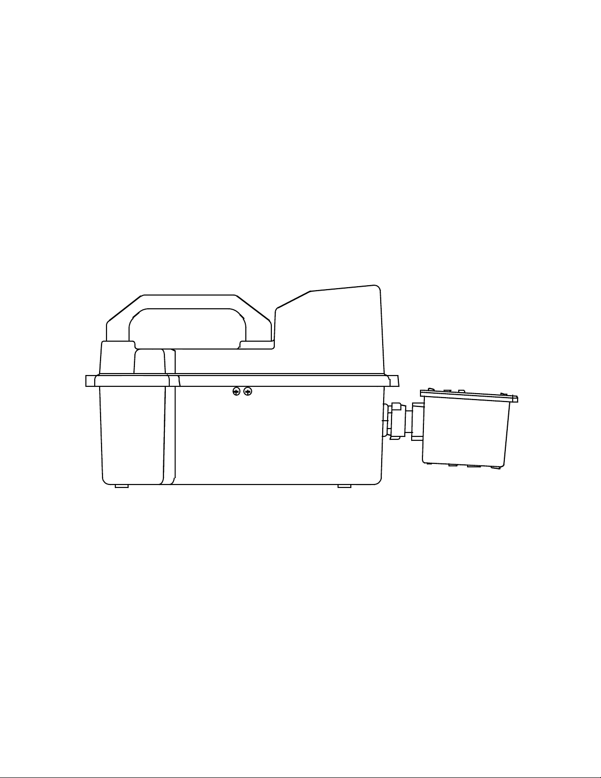
Eagle Case
The Eagle has a plastic case with a full-sized handle. The high-visibility case
is shielded to reduce radio frequency and electromagnetic interference (RFI/
EMI). The system is light-weight and balanced, which makes the Eagle easy
to carry and use for extended periods. A foam rubber gasket between the top
and bottom case components is water- and dust-resistant. You can set the case
into 2.5 in. of water without damage.
Control Panel
The control panel is at the top of the Eagle. The touch-pad buttons reduce the
risk of accidental activ ation. The dot matrix display simultaneously sho ws the
gas reading for all installed sensors. The display also shows information for
each of the Eagle’s program modes.
Buttons
The control panel includes the following six buttons.
Table 3: Eagle Button Functions
Button Function(s)
POWER/ENTER • turns the Eagle on and off.
• used during setup and calibration.
RESET/SILENCE silences and resets audible alarm if the Eagle is programmed for
latching alarms and the Alarm Silence option is on
DISP/ADJ • activates display modes
• enters instructions into the Eagle’s microprocessor
LEL/PPM switches combustible gas detection ranges between %LEL (lower
explosive limit) and PPM (parts per million)
AIR/▲
SHIFT/
1 The Eagle’s alarms are user-adjustable. See “Setup Mode” on page 27.
2 The LEL range is commonly used for safety applications; the PPM range can be used for environmental or other
▼
special applications.
• activates the demand-zero function (automatically adjusts the Eagle
in fresh-air conditions)
• scrolls through the display and settings modes
• scrolls through the calibration and settings modes
• enters instructions into the Eagle’s microprocessor
1
2
Diffusion Eagle Instruction Manual Description: Eagle and Remote Detector • 5
Page 11

Alarm Lights
Two ultra-bright, red, light-emitting diodes (LEDs) provide visual alarms for
gas concentrations and malfunctions. They are mounted on the top rear of the
case for greatest visibility.
Battery Charger Connector
The battery charger connector is mounted on the top right rear of the case.
The external battery charger connects to this connector to recharge nickelcadmium (Ni-Cd) batteries. The continuous operation adapter also connects
to the battery charger connector.
Interface Port
The interface port is for optional data logging or for the remote buzzer. The
port is mounted on the top left rear of the case. When the data logging option
is installed, the Eagle records gas concentrations at programmed intervals and
stores data on gas detected. You can download these measurements through
the interface port to a PC-compatible computer for use in data analysis
programs. Data retrieval requires the Eagle Data Down Loader Kit (with PC
connection cable and software).
The optional remote buzzer or remote buzzer/strobe also connect to the
interface port, and are for use in applications in which a remote alarm
indication is required.
Buzzer
A solid-state electronic buzzer is mounted inside the top of the case. The
buzzer sounds for gas alarms, malfunction, low battery voltage, and as an
indicator during use of the Eagle’s many display and adjustment options.
Circuit Boards
The Eagle circuit boards analyze, record, control, store, and display the
information collected.
The analog PCB is mounted perpendicular to the base of the instrument case.
The sensor leads connect to the analog PCB.
The main PCB is mounted in the top half of the case. It includes the methane
elimination and CAL/SETUP switches.
CAUTION: The circuit boards should be serviced only by authorized
repair personnel.
6 • Description: Eagle and Remote Detector Diffusion Eagle Instruction Manual
Page 12

Methane Elimination Switch
The methane elimination switch (SW1) is mounted near the top right corner
of the main PCB.
For applications where methane is an interfering gas, you can set the methane
elimination switch to eliminate most response to methane (see “Appendix B:
Methane Elimination” on page 58). An external methane elimination switch
is available as an option.
CAL/SETUP Switch
The CAL/SETUP switch (SW2) is mounted near the middle left edge of the
main PCB. This switch controls the Eagle functions available to the user by
disabling the SHIFT/
unable to enter Calibration or Setup mode. (Display mode is available with
either switch setting.) See “Setting User Access” on page 18 to change the
switch setting.
▼ button. Without the use of this button, the user is
Remote Detector
This section describes the Eagle’s Remote Detector. The Remote Detector is
used to detect combustible gas, oxygen, carbon monoxide, and hydrogen
sulfide using four sensors mounted inside a durable plastic case. These
sensors are connected to a printed circuit board, which is also located inside
the case. The Remote Detector includes a buzzer that sounds for gas alarms
and sensor malfunction. The Remote Detector can be connected either
directly to the Eagle, or it can be connected to the Eagle via a 50-foot
extender cable.
Case
The Remote Detector has a durable plastic case with a removable lid secured
by four screws. A removable rubber o-ring gasket mounted in the lid helps
protect the sensors, buzzer, and PCB from water, dust, and the corrosive
effects of gas and vapor.
Diffusion Eagle Instruction Manual Description: Eagle and Remote Detector • 7
Page 13
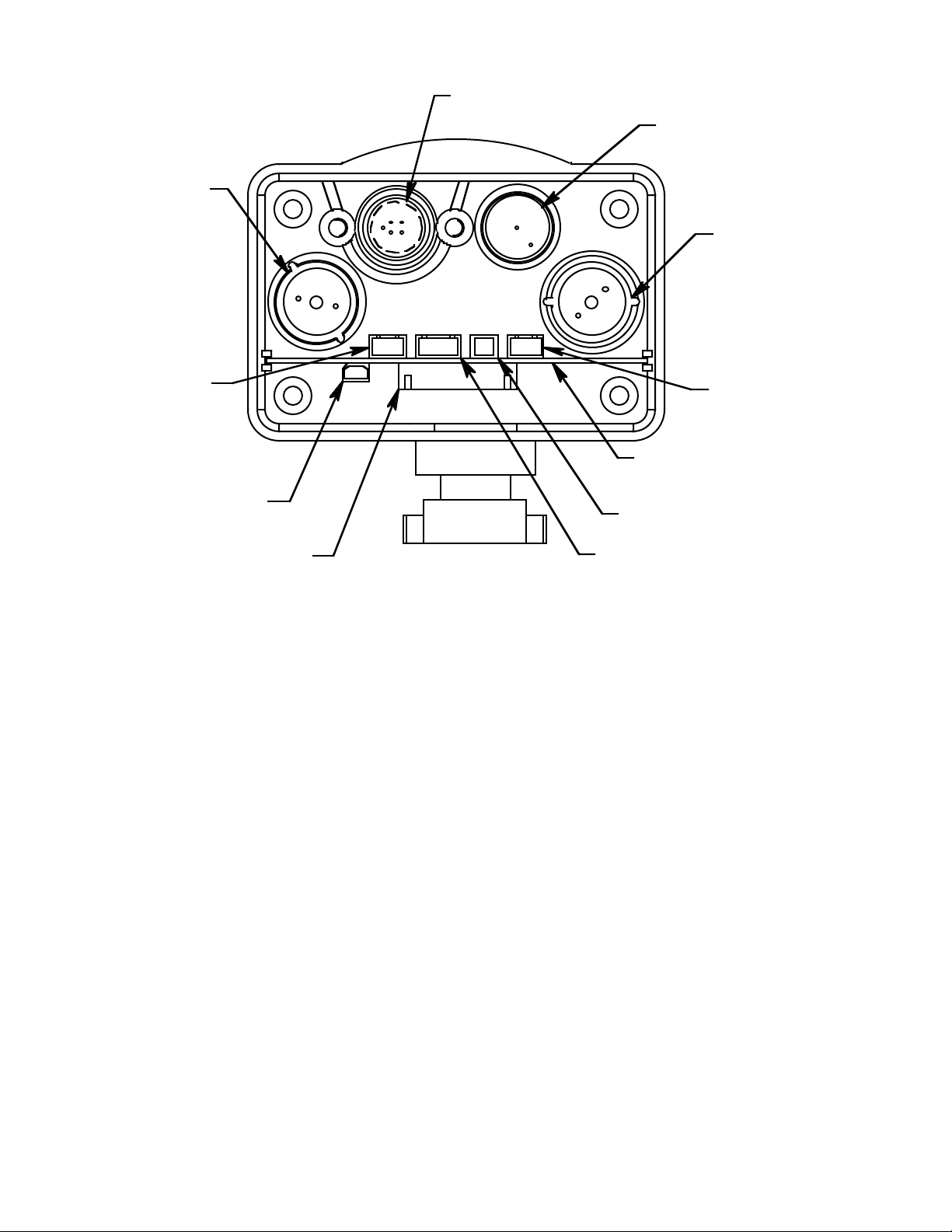
H2S
Combustible, Shown
w/out Bracket
Oxygen
CO
CN4
(H2S)
CN1
(CO)
Interconnect
PCB
CN5
(Buzzer)
CN6
Interconnect Circuit Board
CN2 (Oxygen)
CN3 (Combustible)
The Remote Detector has a printed circuit board (PCB) located inside its
case, the interconnect PCB. The PCB is mounted perpendicular to the base of
the Remote Detector’ s case. It is positioned near the connector used to attach
the Remote Detector to the Eagle. The PCB provides connection points for
the Remote Detector’s four sensors, described below, and a connection point
for the Remote Detector’s buzzer.
8 • Description: Eagle and Remote Detector Diffusion Eagle Instruction Manual
Page 14

Sensors
Under normal conditions, the Eagle’s standard sensors have an operating life
of approximately two years. To replace the sensors, open the case by
unscrewing the four screws that secure the lid to the case. (See “Replacing
Sensors” on page 52 for more details.)
Combustible gas sensor
The combustible gas (LEL) sensor is mounted with the flame arrestor
extending outside the case to allow the ambient air to diffuse into the sensor.
Five pins extend from the top of the sensor. The sensor cable connects to the
pins on one end and terminates in a four-position connector , which plugs into
the COMB (CN3) socket on the interconnect printed circuit board (PCB)
inside the Remote Detector.
The LEL sensor detects combustible gas and v apors in the atmosphere with a
catalytic platinum element. The reaction of gas with oxygen on the catalyst
causes a change in the resistance of the element, which is converted by the
Eagle into a reading of combustible gas concentration.
Oxygen sensor
The oxygen (O2) sensor is mounted with its face behind a perforated hole
pattern covered by a hydrophobic membrane to allow the ambient air to
diffuse into the sensor. A multi-pin plug connects the O2 sensor to the OXY
(CN2) socket on the interconnect PCB. This socket sticks up higher than the
rest.
The O2 sensor is an electrochemical cell, which reacts to the oxygen in the
atmosphere and produces a voltage proportional to the oxygen concentration.
This voltage is converted by the Eagle into a reading of oxygen
concentration.
Diffusion Eagle Instruction Manual Description: Eagle and Remote Detector • 9
Page 15

Standard toxics (CO and H2S) sensors
The carbon monoxide (CO) and hydrogen sulfide (H2S) sensors are
physically very similar. They both have cylindrical bodies and they are
mounted with their faces behind a perforated hole pattern covered by a
hydrophobic membrane to allow the ambient air to diffuse into the sensors.
The CO sensor connector connects to the CO (CN1) socket and the H
sensor connector connects to the H
S (CN4) socket on the interconnect PCB.
2
S
2
The toxics sensors are electrochemical cells, which react to the target gas in
the atmosphere, producing a current proportional to the concentration of gas.
The current is converted by the Eagle into a reading of target gas
concentration.
Buzzer
A solid-state electronic buzzer is mounted inside the lid of the Remote
Detector’s case. The buzzer sounds for gas alarms, malfunction, low battery
voltage, and as an indicator during use of Eagle’s many display and
adjustment options.
Connector
The Remote Detector has a single, 18-pin male connector with a retaining
ring. The connector is attached to the Remote Detector’s case by three
screws. The connector allo ws the Remote Detector to be attached to the Eagle
in two ways, as stated abov e. (To attach the Remote Detector to the Eagle, see
“Starting Up the Eagle” on page 11.)
10 • Description: Eagle and Remote Detector Diffusion Eagle Instruction Manual
Page 16
Operation
The Eagle has four operating modes: normal operating mode, display mode,
setup mode, and calibration mode. This section describes the Eagle in normal
operating mode. It includes procedures to start up the Eagle, set various
detection options for the combustible gas channel, and shut down the Eagle.
NOTE: The screens illustrated in this section are intended as examples only.
Starting Up the Eagle
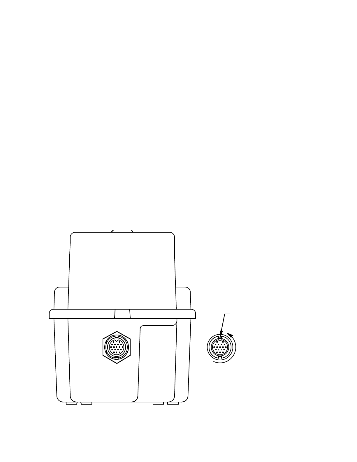
1. Connect the Remote Detector either directly to the Eagle or use the 20foot or 50-foot extender cable. To make this connection, follow these
steps:
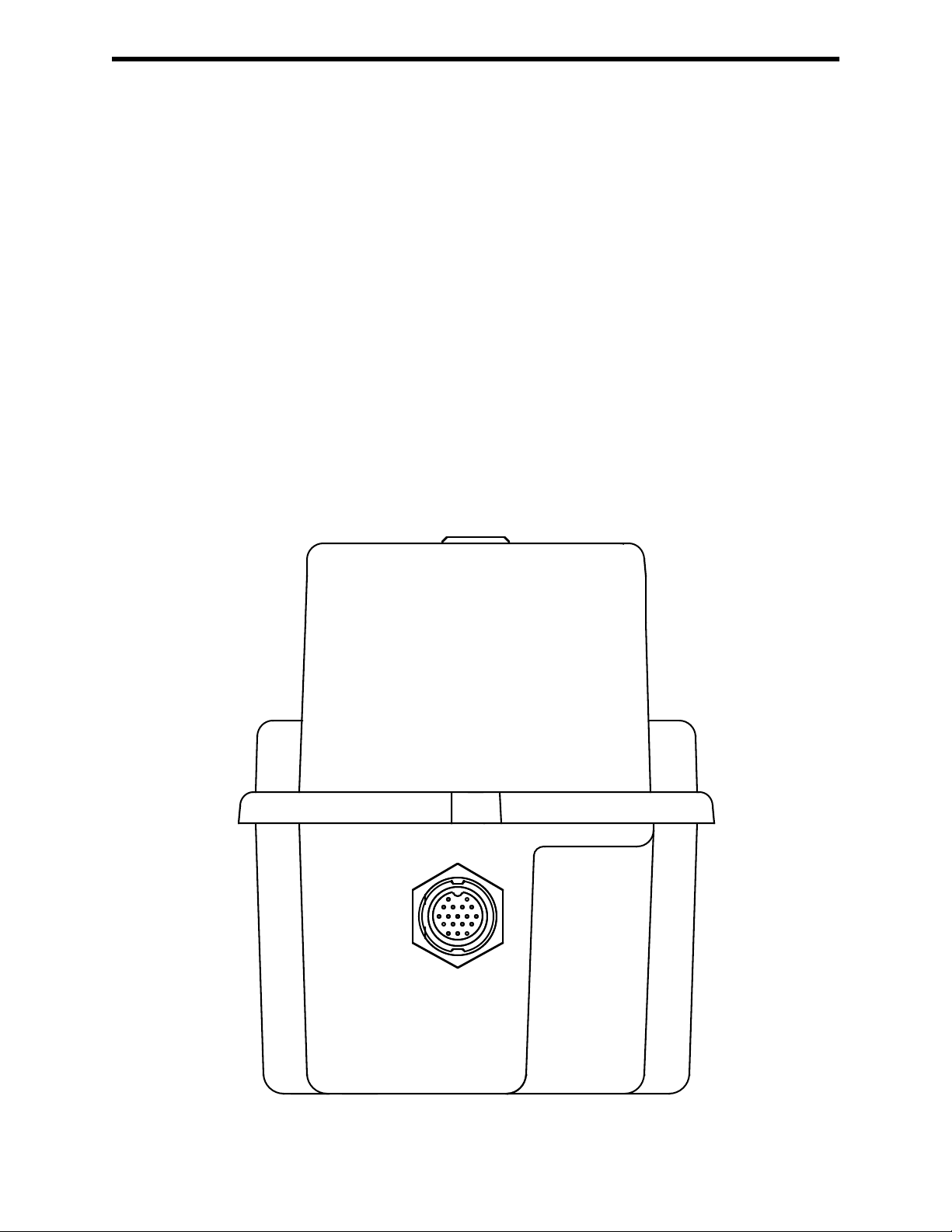
• Find the connector for the Remote Detector on the front end of the
The screens displayed by your Eagle model may be slightly
different.
Eagle’s bottom case assembly.
Eagle
Connector
Diffusion Eagle Instruction Manual Operation • 11
Page 17
•To attach the Remote Detector directly to the Eagle, position the
Remote Detector coupling in the unlocked position as shown below.
Then line up the tab inside the connector on the Remote Detector
with the notch inside the connector on the Eagle. Gently push the
Remote Detector toward the Eagle. Turn the coupling clockwise on
the connector of the Remote Detector to secure the Remote Detector
to the Eagle’s bottom case assembly.
Locked Position
Coupling shown in
Unlocked Position,
Counterclockwise to Locked
Locked Position
12 • Operation Diffusion Eagle Instruction Manual
Page 18
NOTE: If the Remote detector has been disconnected from the Eagle
for more than a few minutes, such as during shipment, wait
15 minutes after connecting the Remote detector before
turning on the Eagle to allow the CO and H
S sensors to
2
stabilize.
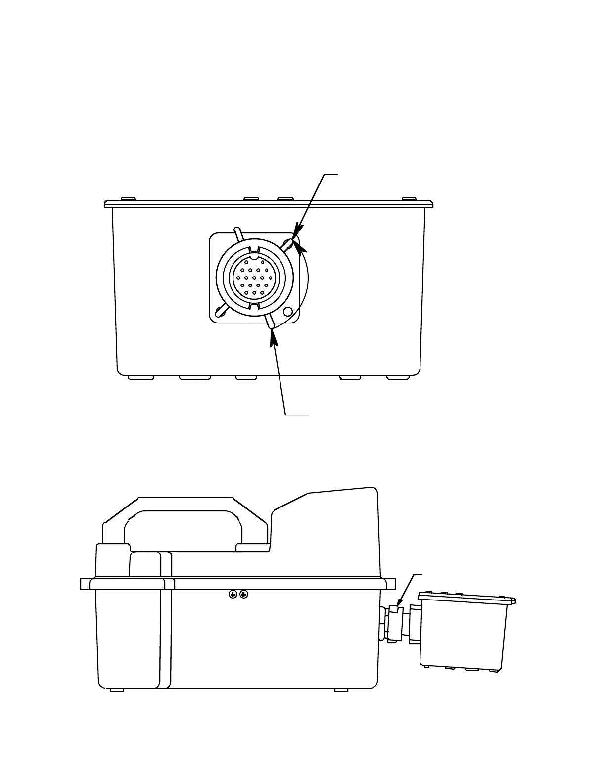
•To attach the Remote Detector using an extender cable, carefully fit
the end of the extender cable that has a coupling to the Eagle’s
connector. Make sure to line up the tabs inside the coupling with the
matching notches in the cable connector as shown below. Then line
up the tab on the extender cable connector with the notch inside the
connector on the Eagle. Gently push the extender cable toward the
Eagle. Turn the coupling clockwise on the extender cable to secure
the cable to the Eagle’s bottom case assembly. Next, carefully fit the
other end of the extender cable to the connector on the Remote
Detector. Position the Remote Detector coupling in the unlocked
position as shown above. Then line up the tab inside the Remote
Detector connector with the notch inside the connector on the Eagle.
Gently push the extender cable toward the Remote Detector. Tighten
the coupling on the Remote Detector connector to secure the extender
cable to the Remote Detector.
Align Keys in Key
Way For Assembly
Rotate to Lock
Eagle
Connector
Diffusion Eagle Instruction Manual Operation • 13
Cable End
Connector
Page 19
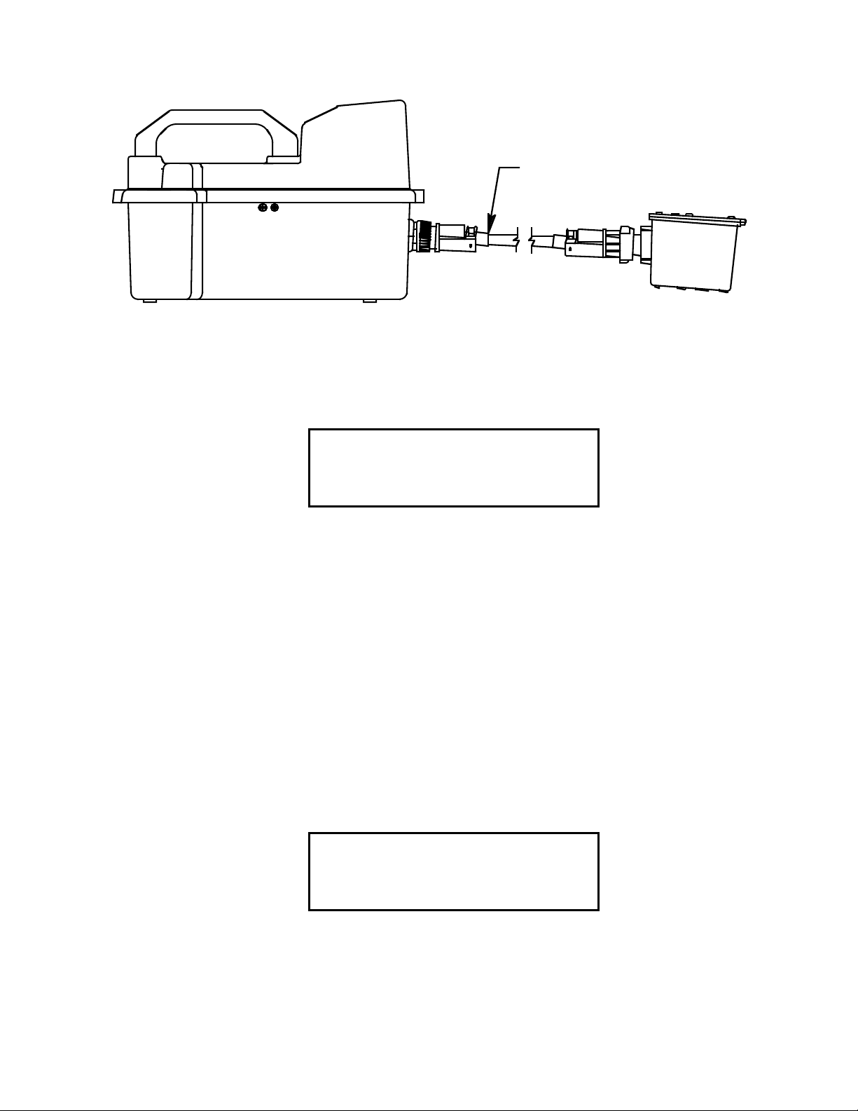
Extender Cable
2. Press and briefly hold down the POWER/ENTER button. If the Lunch
Break feature is on (see page 38), the Resume Datalog screen displays.
(If the Lunch Break feature is off, the Battery Voltage screen displays.)
UDT
E
R
S
M
YE
O
N
E
A
A
L
OG
?
5
I
A:
S
:
R
I
D
L
S
P
AY
• Press the AIR/
▲ button to continue accumulating time-weighted
average (TWA) and PEAK readings from the last time the Eagle was
used. (The short-term exposure limit [STEL] reading is reset each
time the Eagle is turned on.) The Battery Voltage screen displays.
• Press the DISP/ADJ button to restart these measurements. The
Battery Voltage screen displays.
If you do not press the
AIR/▲ or DISP/ADJ button within 5 seconds, the
Eagle automatically resumes datalog readings and displays the Battery
Voltage screen.
The Battery Voltage screen displays the minimum usable and actual
battery voltage (for example, 6.0V). If the battery voltage is too low, the
Eagle will not continue.
TERY
BA
T
MIN
BA
NO
.4.5V
TERY
T
W
60V.
14 • Operation Diffusion Eagle Instruction Manual
Page 20

NOTE: The following screen only displays if the data logging option is
installed. If the data logging option is not installed, the Self
Diagnosis screen displays after the Battery Voltage screen.
This message displays the date and time as set in Setup mode. The data
logging option uses this information to record the time and date of sample
and alarm events.
R
17 1
PA
130
4
998
:
The following two screens display while the Eagle checks itself for
proper operation. The Eagle alerts you if a malfunction occurs.
S
EL
F
GN
DIA O
0
1
S
E
O
G
T
ND BY
ST
A
CH
<X
H
><O Y
4
2
>
S
<<
C>O
C
S
O
O
S
I
NDS
>
When the Eagle successfully completes its self check, the OK message
displays in place of the STAND BY message, then the normal operating
screen displays. The normal screen displays fresh-air concentrations for
all gases. The Eagle sounds a double tone to indicate it is in normal
operation.
4
CH
OY
X
H
2
S
C
O
0.9
2
0
L
EOLL%
%
V
0.0
P
PPPMM
0
CAUTION: Do not use gas from a cigarette lighter to test r esponse to
combustibles. Exposing the combustible gas sensor to
uncontrolled high concentrations of gas will reduce
response and sensor life.
Diffusion Eagle Instruction Manual Operation • 15
Page 21

3. Verify that the Eagle is operating correctly . Use the RKI Bump Test Kit to
easily verify correct operation of the Eagle.
WARNING: If the Eagle does not respond to verification, take it to a kno wn
“fresh-air” environment, then perform the demand zero
procedure described in “Preparing for Calibration” on page 46.
Repeat step 3 before using the Eagle in a potentially hazardous
location. If readings are not within 10% of the gas
concentrations, calibrate the Eagle as described in “Calibrating
the Eagle” on page 47.
Normal Operation
The Eagle continuously monitors the atmosphere around the Remote
Detector and displays the gas concentrations present for its target gases. In a
low-light en vironment, press an y b utton to turn on the display backlight. (See
“Updating the Back Light Setting” on page 41 to program backlight
duration.) If the Confirmation Beep option is turned on, the Eagle beeps once
every 15 minutes to verify that it’s on the job.
To use an extender cable, see “Starting Up the Eagle” on page 11, insert the
Remote Detector into the monitoring area, then wait a few seconds for a
response.
Monitoring Combustible Gas in the PPM Range
1. Start the Eagle in the LEL range as described in “Starting Up the Eagle”
on page 11.
2. Allow the combustibles sensor to stabilize (3 to 5 minutes). This
stabilization period is required for the PPM range only.
3. Press the LEL/PPM button. The Eagle displays PPM in place of LEL%
for combustible gas, and the gas reading displays in parts per million.
4. If the PPM reading is not zero, take the Eagle to a fresh air environment,
then perform the demand zero procedure as described in “Preparing for
Calibration” on page 46.
NOTE: For the data logging option, combustible gas readings are logged in
%LEL regardless of the LEL/PPM setting.
16 • Operation Diffusion Eagle Instruction Manual
Page 22

Monitoring Combustible Gases Other than Methane
If the combustible gas sensor is calibrated to methane (CH4), use
Table 4 to determine the concentration of combustible gases other than
methane. This table is based on Eagles in full response mode (methane
elimination switch set to CH4) and calibrated to methane. Multiply the
display reading by the factor in the appropriate column in the table. For
example, if you are using the Eagle to detect hexane and the display reads
10% LEL, the actual hexane reading is
10% x 3.00 = 30% LEL hexane.
WARNING: The Eagle’s alarms are initiated by the DISPLAY reading not
the FACTORED reading. If you are monitoring for hexane as
in the example above and the lo w alarm is set for 10% LEL, the
Eagle will initiate a low alarm at 30% LEL hexane (display
reading of 10% LEL).
To determine the concentration of other combustible gases with the Eagle in
methane elimination mode, see Table 7 on page 59.
Table 4: Full Response Mode Conversion Factors (Methane Calibration)
Target Gas
Benzene 2.80 0.67
Ethane 1.40 0.84
Ethanol 2.25 1.5
Ethylene 1.58 0.4
Hexane 3.00 0.67
Hydrogen 1.65 1.4
IPA 2.83 1.13
Isobutane 1.93 1.21
MEK 3.00 1.08
Methane 1.00 1.00
Methanol 2.33 2.57
Propane 2.30 0.92
LEL Factor
(Methane Calibration)
PPM Factor
(Methane Calibration)
Propylene 2.00 0.80
Toluene 2.80 0.67
Diffusion Eagle Instruction Manual Operation • 17
Page 23

Setting User Access
The CAL/SETUP switch controls the Eagle functions available to the user.
The switch setting does not affect the Eagle’s ability to display gas readings
and indicate gas and malfunction alarms.
1. Turn off the Eagle.
2. Unscrew the two large screws on the top of the case.
3. Turn over the top half of the case, and locate the CAL/SETUP switch
(SW2) near the middle along one edge of the main processor board.
CAUTION: The Methane Elimination switch (SW1) is on the opposite
edge of the board near the front end. DO NOT confuse
these two switches.
4. Place the CAL/SETUP switch in the appropriate position.
•To give the Eagle access to all modes, place the switch in the ON
position.
•To limit the Eagle to normal operating and display modes, place the
switch in the OFF position. (The Eagle prevents access to the setup
and calibration modes by disabling the SHIFT/
▼ button.)
5. Place the top of the case in its original position, then secure it with the
large screws you loosened in step 2.
6. Turn on the Eagle.
NOTE: Make sure the Eagle’s calibration is current and the setup options
appropriate and safe for the operating environment before placing
the CAL/SETUP switch in the OFF position.
Turning Off the Eagle
To turn off the Eagle, press and hold down the POWER/ENTER button until
GOOD-BYE displays, then release the button. (You must wait for GOODBYE to disappear before you can turn on the Eagle again.)
18 • Operation Diffusion Eagle Instruction Manual
Page 24

Alarms
Alarm Indications
This section describes the Eagle’s audible and visual alarm indications for
gas, over range, low battery, and sensor failure alarms. This section also
describes how to reset gas alarms.
The default alarm settings are listed in Table 2, “Standard Sensor
Specifications” on page 4. The alarm settings are user-adjustable as described
in “Updating the Alarm Point Settings” on page 36.
NOTE: The screens illustrated in this section are intended as examples only.
First gas alarm
If a channel’s gas reading exceeds the first alarm setting (falls below for the
oxygen channel):
The screens displayed by your Eagle model may be slightly
different.
4
CH
OY
X
H
2
S
C
O
0.9
2
0
0.0
0
L
EOLL%
V
P
PPPMM
ALM
%
11
• ALM1 displays in the alarm field for that channel.
• The channel’s display line flashes.
• The buzzer sounds a pulsed tone.
• The alarm lights flash.
Second gas alarm
If a channel’s gas reading exceeds the second alarm setting:
4
CH
OY
X
H
2
S
C
O
0.9
2
0
0.0
0
L
EOLL%
V
P
PPPMM
%
A
LM
25
• ALM2 displays in the alarm field for that channel.
• The channel’s display line flashes.
• The buzzer sounds a pulsed tone.
• The alarm lights flash.
Diffusion Eagle Instruction Manual Alarms • 19
Page 25

STEL alarm (toxics only)
If a toxic gas channel’s average gas reading for the past 15 minutes exceeds
the STEL alarm setting:
4
CH
OY
X
H
2
S
C
O
0.9
2
1
0
L
EOLL%
%
V
0.5
P
PPPMM
0
STE
L
• STEL displays in the alarm field for that channel.
• The channel’s display line flashes.
• The buzzer sounds a pulsed tone.
• The alarm lights flash.
TWA alarm (toxics only)
If a toxic gas channel’s average gas reading for the past 8 hours exceeds the
TWA alarm setting:
4
CH
OY
X
H
2
S
C
O
0.9
2
1
0
L
EOLL%
%
V
0.0
P
PPPMM
0
T
WA
•TWA displays in the alarm field for that channel.
• The channel’s display line flashes.
• The buzzer sounds a pulsed tone.
• The alarm lights flash.
Over range alarm
If a channel’s gas reading exceeds that channel’s full-scale setting:
4
CH
OY
X
H
2
S
C
O
0.0
4
0
L
EOLL%
%OVER
V
0.0
P
PPPMM
0
•OVER displays in the alarm field for that channel.
• The channel’s display line flashes.
• The buzzer sounds a pulsed tone.
• The alarm lights flash.
20 • Alarms Diffusion Eagle Instruction Manual
Page 26

Low battery alarm
When the battery charge drops near the lower limit, the Eagle displays the
following screen (BAT flashes). For alkaline batteries, you have
approximately 3 hours of use remaining; for Ni-Cd batteries you have
approximately 15 minutes of use remaining.
B
A
T
CH
OY
X
2
H
S
CO
0.9
2
0
0.0
0
L
EOLL%
V
P
PPPMM
%
Low Battery
Warning
4
When the battery voltage drops to the minimum limit, the following screen
displays, the alarm lights are on continuously , and the b uzzer sounds a steady
tone. The Eagle is not operational as a gas monitoring device when this
screen displays.
TERY
BA
T
MIN
H
C
A
BA
TTE
.
G
N
4.5V
E
RY
Low Battery
ALARM
NOTE: If you are using the optional data logging accessory and the Eagle
goes into Low Battery ALARM, shut off the Eagle in order to save
the current data logging session.
Sensor failure alarm and emergency operation
The Eagle continuously monitors itself for proper operation. If a malfunction
occurs, the Eagle alerts you with audible and visual alarms.
If a sensor fails during start-up or normal operation:
IL
FA
SENSOR
<X
><O
<<
>
Y
>
>
• The message FAIL SENSOR displays.
• The failed sensor displays in parenthesis.
• The buzzer sounds a steady tone.
• The alarms lights flash.
Diffusion Eagle Instruction Manual Alarms • 21
Page 27

If the sensor failed during start-up, the Eagle continues with the normal
start-up sequence after the fail screen displays. When the normal screen
displays, the Eagle replaces the gas reading for the failed sensor with xxxxx.
If the sensor fails during normal operation and you want to continue
monitoring for the remaining target gases, turn the Eagle off, then follow the
appropriate start-up sequence. When the normal screen displays, the Eagle
replaces the gas reading for the failed sensor with xxxxx.
4
CH
OY
X
H
2
S
C
O
0
L
EOLL%
%xxxxx
V
0.0
P
PPPMM
0
Resetting Gas Alarms
You can set the Eagle’s gas alarms for latching or self-resetting alarms
(see “Updating the Alarm Latching Setting” on page 38).
Self-resetting alarms
Self-resetting alarms automatically shut off and reset when the gas reading
falls below (or rises above for oxygen) the alarm setting. You cannot silence
or reset self-resetting alarms.
Latching alarms
You can set latching alarms with or without Alarm Silence (see “Updating the
Alarm Silence Setting” on page 39).
With Alarm Silence on:
When the Eagle goes into gas alarm, press the RESET/SILENCE button to
silence the buzzer. The LEDs continue to flash, and the Eagle continues to
display the current alarm level.
The gas reading must fall below (or rise above for oxygen) the low alarm
(ALM1) setting before you can reset the alarm. Press the RESET/SILENCE
button to reset the alarm. The LEDs turn off and the Eagle returns to the
normal screen.
With Alarm Silence off:
The gas reading must fall below (or rise above for oxygen) the low alarm
(ALM1) setting before you can reset the alarm. Press the RESET/SILENCE
button to reset the alarm. The LEDs and b uzzer turn of f, and the Eagle returns
to the normal screen.
NOTE: With Alarm Silence off, you cannot silence the buzzer while the gas
reading is above (below for oxygen) the low alarm (ALM1) setting.
22 • Alarms Diffusion Eagle Instruction Manual
Page 28

Display Mode
The Eagle has four operating modes: normal operating mode, display mode,
setup mode, and calibration mode. With the Eagle in display mode, you can:
• set user and station IDs
• display peak readings
• display elapsed time
• display TWA and STEL readings (toxic gases only)
• display battery voltage
• display date and time (data logging option only)
• clear the data log (data logging option only)
• display remaining log time (data logging option only)
To enter display mode, from the normal screen press the DISP/ADJ button.
To scroll from one screen to the next press the DISP/ADJ button.
NOTE: Each screen displays for 20 seconds. If you do not press the DISP/
ADJ button to scroll to the next screen within 20 seconds, the Eagle
automatically returns to the normal operating screen.
User and Station ID Screen
This screen displays only if the user ID function is activated (see “Turning
the User ID Function On or Off” on page 39). Each ID contains 10
characters. Uppercase letters, numbers, asterisks (*) and a blank space are
available characters.
Use this screen to identify user, location, or other information. If your Eagle
has the data logging option, the User and Station ID provides a way to
identify the user and location of exposure. The User and Station ID are sa v ed
to the Data Logger when you turn off the Eagle, so you can update the IDs for
each data logging session.
RD
SE
U
S
A
I
*
*********
TI
OT
*
*********
D
IN
Diffusion Eagle Instruction Manual Display Mode • 23
Page 29

To enter a user and station ID:
To scroll to the next screen at any time, press the DISP/ADJ button.
1. Press the POWER/ENTER button. The first character under USER ID
flashes (* is default).
2. Press the AIR/
▲ and SHIFT/▼ buttons to scroll through the available
characters. (The asterisk and blank space are between the set of letters
and numbers.)
3. When the desired character displays, press the POWER/ENTER b utton to
enter the character and go to the next character.
4. Repeat steps 2 and 3 for the remaining 19 characters.
After you enter the last character, the Peak screen displays.
Peak Screen
The Peak screen displays the highest (lowest for O2) concentrations detected
since the Eagle was turned on. Peak readings are stored in the Eagle’s
memory until a higher level is detected or the Eagle is turned off.
The Lunchbreak “RESUME” option enables the Eagle to remember peak
readings when it is turned off. See “Starting Up the Eagle” on page 11.
4
P
E
A
K
CH
OY
X
H
2
S
C
O
0.9
2
0
0.0
0
L
EOLL%
V
P
PPPMM
%
Elapsed Time Screen
The Elapsed Time screen displays the time in minutes since the Eagle was
last turned on.
TI
OPE
M
ENI
M
RA I
T
40
2
U
N
T
E
ON
SI
24 • Display Mode Diffusion Eagle Instruction Manual
Page 30

TWA/STEL Screen
The TWA/STEL screen displays the time-weighted average (TWA) and the
short-term exposure limit (STEL) readings for toxic gases only.
The TWA reading is the average reading during the last 8 hours. If 8 hours
have not elapsed since the last time the TWA/STEL reading was cleared, the
average is still calculated over 8 hours. The missing time is assigned a 0 v alue
for readings.
The STEL reading is the average reading during the last 15 minutes.
S
W
A
T
2
S
H
C
O
0.0
0
TEL
0.0
0
P
PPPMM
Battery Voltage Screen
The Battery Voltage screen displays the minimum operating voltage and
present battery voltage. New alkaline batteries typically measure 6.0 V ; fullycharged Ni-Cd batteries typically measure 5.2 V. This screen also displays
when you turn on the Eagle.
TERY
BA
T
MIN
BA
NO
.4.5V
TERY
T
W
60V.
NOTE: The remaining screens only display if your Eagle includes the data
logging option. If your Eagle does not include the data logging
option, press the DISP/ADJ button to return to the normal screen.
Date/Time Screen
The date/time screen displays the current date and time. You can set the date
and time in Calibration or Setup mode (see page 43).
R
17 1
PA
130
4
998
:
Diffusion Eagle Instruction Manual Display Mode • 25
Page 31

Clear Data Logger Screens
CAUTION: Once you clear the Data Logger, you cannot retrieve any
data previously stored in the Data Logger.
The Clear Data Logger screens allow you to clear the Data Logger storage to
accept new data. (Press the DISP/ADJ button to go to the Remaining Log
Time screen). You can set the Eagle to overwrite the oldest data when the data
log is full (see page 42).
CRD
To clear the data log:
L
L
YE
O
N
E
A
OG
S
GR
:
:
A
T
A
E
A
D
?
I
R
I
L
S
P
AY
1. With the above screen displayed, press the AIR/
▲ button.
A confirmation message displays.
A
YE
O
N
R
YO
E
S
R
U
:
S
:
U
E
?
I
A
R
I
D
L
S
P
AY
2. Press the AIR/▲ button to confirm that you want to clear the data log.
The Eagle displays CLEARING DATA, then displays CLEARED OK.
The data log is cleared and the remaining log time value is reset.
Remaining Log Time Screen
The Remaining Log Time screen displays the time remaining until the Data
Logger memory is full. The remaining time depends on how often the Eagle
stores data to the data log and how many channels are active.
O
L
H
EG
R
TI
G
0
3
UO
R
A
IM
E
M
0.
0
S
N
I
N
Press the DISP/ADJ button once more to return to the normal screen.
26 • Display Mode Diffusion Eagle Instruction Manual
Page 32

Setup Mode
NOTE: The screens illustrated in this section are examples only. The screens
The Eagle has four operating modes: normal operating mode, display mode,
setup mode, and calibration mode. This section describes the setup mode. In
setup mode, you can:
• update the battery type setting
• update channel settings
• update the combustible gas channel’s units of measure
• update the alarm point settings
• update the Eagle’s serial number
• turn the lunch break function on or off
• update the alarm latching setting
• update the alarm silence setting
displayed by your Eagle model may be slightly different.
• turn the user ID function on or off
• update the auto calibration settings
• update the back light setting
• turn the auto fresh air function on or off
• update the data interval time setting (data logging option only)
• update the log data over write setting (data logging option only)
• update the time calibration setting (data logging option only)
• update the date and time settings (data logging option only)
• turn the zero follower on or off for each channel
• turn the confirmation beep on or off
• return to default settings (three default options)
The Eagle is pre-set to suit most applications. Follow these instructions only
if required.
Diffusion Eagle Instruction Manual Setup Mode • 27
Page 33

Tips for Using Setup Mode
•To select a menu option, use the AIR/▲ or SHIFT/▼ button to place the
prompt next to the menu option, then press the PO WER/ENTER button to
select the menu option.
•To exit setup mode, from the main menu place the prompt next to the last
menu option, START MEASUREMENT, then press the POWER/ENTER
button. The Eagle begins its normal start-up sequence.
Entering Setup Mode
WARNING: The Eagle does not detect gas or display readings while in
setup mode. The CAL/SETUP switch (SW2) must be in the
ON position to enter setup mode.
1. Take the Eagle to a non-hazardous location, and turn the power off.
2. Press and hold down the AIR/
▲ and SHIFT/▼ buttons, then press the
POWER/ENTER button. The main menu displays. It displays four menu
options at a time. Press the AIR/
▲ or SHIFT/▼ button to view additional
menu options.
ER
B
T
>
A
ASGC TON
LE
L
ALA
Y
T
O
B
M
%O
R
RP
M
OI
E
Y
P
T
A
I
N
L
O
V
%
T
S
N
S
I
(
)
C
H
Updating the Battery Type Setting
This setting allows you to select between alkaline and Ni-Cd batteries. The
Eagle uses this setting to make sure adequate time is given between the low
battery warning and low battery alarm. This setting has no effect on battery
charging.
1. From the main menu, select the BATTERY TYPE menu option.
B
A
R
Y
T
E
TP
E
Y
T
L
I
AELKA
28 • Setup Mode Diffusion Eagle Instruction Manual
N
Page 34

2. Press the AIR/▲ or SHIFT/▼ button to display the desired setting.
CAUTION: This setting should always match the type of batteries
(alkaline or Ni-Cd) installed in the Eagle. If this setting
does not match the installed batteries, the time between
low battery warning and low battery alarm may be less
than expected.
3. Press the POWER/ENTER button to enter the setting and return to the
main menu.
Updating Channel Settings
This procedure describes how to update channel settings for the combustible
gas, oxygen, and toxic gas channels.
CAUTION: Verify that the correct sensor is installed before you
update a channel’s settings.
Updating combustible gas channel settings
This section describes how to update the target gas label, set a custom gas
label, and update the full-scale PPM setting for the combustible gas channel.
Updating the target gas label
1. From the main menu, select the GAS COMBINATIONS menu option.
>
CH
4
OY
X
H
2
S
CO
2. Use the AIR/
▲ or SHIFT/▼ button to place the prompt next to the
combustible gas channel (in this example CH4).
3. Press the POWER/ENTER button. The combustible gas target gas label
flashes. This indicates that this setting can now be updated.
4. Press the AIR/
▲ or SHIFT/▼ buttons to display the a vailable comb ustible
gas target gas labels (CH4, HEX, H2, ***, and NOT USED).
NOTE: Select the HEX or *** setting for Methane Elimination
(see “Appendix B: Methane Elimination” on page 58 for more
information.)
Diffusion Eagle Instruction Manual Setup Mode • 29
Page 35

5. Press the POWER/ENTER button to enter the new target gas label.
A screen displays that shows the full-scale PPM setting, which
corresponds to 100% LEL, and display increments for the target gas label
you selected. If you select *** as the gas label, you must update the fullscale PPM setting to correspond to 100% LEL for the target gas.
The number in parenthesis indicates the display increment for that
portion of the PPM range. In the example below, the PPM reading would
display in increments of:
•5 from 0 to 100 ppm
• 50 from 100 to 1000 PPM and 1000 to 10,000 PPM
• 250 from 10,000 to 50,000 PPM
>
*
*
*
0
50
0
1
0
100
0
P
00 PM
)
(
5
(
5)0
1000(5)0
5000
0
(
0
2
)
5
0
If you entered a label other than ***, continue with step 6. If you entered ***,
go to the next section, “Setting a custom target gas label.”
6. Press the POWER/ENTER button to return to the Gas Combinations
menu.
7. To exit the Gas Combinations menu, press the SHIFT/
prompt is next to Channel 4, then press the SHIFT/
▼ button until the
▼ button again. The
ESCAPE message displays.
8. Press the POWER/ENTER button. The message SAVING DATA
displays, then the main menu displays.
Setting a custom target gas label
1. With the prompt next to the target gas label setting (***), press the
POWER/ENTER button. The first asterisk flashes.
2. Press the AIR/
▲ and SHIFT/▼ buttons to display the desired character.
Available characters are A through Z, 0 through 9, and a blank space.
30 • Setup Mode Diffusion Eagle Instruction Manual
Page 36

3. Press the POWER/ENTER button to enter the displayed character. The
next character flashes.
4. Repeat steps 2 and 3 to enter the remaining characters. When you enter
the last character, the prompt flashes.
Updating the full-scale PPM setting
CAUTION: The full-scale PPM setting must correspond to 100% LEL
for the target gas in order for the Eagle to display
accurate PPM readings for the combustible gas channel.
1. Press the SHIFT/
▼ button to place the prompt in the second line, then
press the POWER/ENTER button to update the full-scale setting. The
full-scale setting flashes.
The maximum full-scale setting for the combustible gas channel is
50,000 PPM; the minimum setting is 1000 ppm. The default setting is
50,000 ppm.
2. Press the AIR/
▲ and SHIFT/▼ buttons to display the desired full-scale
setting (see Table 5), then press the POWER/ENTER button to enter the
setting. The prompt flashes.
Table 5: full-scale PPM Readings
Equivalent to 100% LEL
Target Gas full-scale Setting
Methane (CH
Hexane 11,000 ppm
Hydrogen 40,000 ppm
) 50,000 ppm
4
Pentane 15,000 ppm
Styrene 9,000 ppm
IPA 20,000 ppm
Isobutane 18,000 ppm
Propane 21,000 ppm
Propylene 20,000 ppm
Toluene 11,000 ppm
Ethane 30,000 ppm
Ethanol 33,000 ppm
Benzene 12,000 ppm
Diffusion Eagle Instruction Manual Setup Mode • 31
Page 37

Returning to the main menu
1. Press the SHIFT/▼ button. The ESCAPE message displays. (Press the
▲ button to return to the previous screen.)
AIR/
2. Press the POWER/ENTER button to save the new setting. The OTHER
GAS SET message displays, then the Gas Combinations menu displays.
3. To exit the Gas Combinations menu, press the SHIFT/
prompt is next to Channel 4, then press SHIFT/
▼ again. The ESCAPE
▼ button until the
message displays.
4. Press the POWER/ENTER button. The message SAVING DATA
displays, then the main menu displays.
Updating oxygen channel settings
This section describes how to update the target gas label, full-scale setting,
and display increment setting for the oxygen channel.
Updating the target gas label
1. From the main menu, select the GAS COMBINATIONS menu option.
CH
4
>
OY
X
H
2
S
CO
2. Use the AIR/
▲ or SHIFT/▼ button to place the prompt next to the oxygen
channel (in this example OXY).
3. Press the POWER/ENTER button. The oxygen target gas label flashes.
This indicates that this setting can now be updated.
4. Press the AIR/
▲ or SHIFT/▼ buttons to display the available oxygen
target gas labels (OXY, ***, and NOT USED).
CAUTION: The *** setting is not intended for customer setup.
Contact RKI Instruments, Inc., before using this setting
for the oxygen channel.
5. Press the POWER/ENTER button to enter the new target gas label.
6. To exit the Gas Combinations menu, press the SHIFT/
prompt is next to Channel 4, then press the SHIFT/
▼ button until the
▼ button again. The
ESCAPE message displays.
7. Press the POWER/ENTER button. The SAVING DATA message
displays, then the main menu displays.
32 • Setup Mode Diffusion Eagle Instruction Manual
Page 38

Updating the full-scale setting
1. Press the SHIFT/▼ button to place the prompt in the second line, then
press the POWER/ENTER button to update the full-scale setting. The
full-scale setting flashes.
The maximum full-scale setting for the oxygen channel is 40.0 VOL%;
the minimum setting is 25.0 VOL%. The default setting is 40.0 VOL%.
2. Press the AIR/
▲ and SHIFT/▼ buttons to display the desired full-scale
setting, then press the POWER/ENTER button to enter the setting. The
prompt flashes.
Updating the display increment setting
1. Press the SHIFT/▼ button to place the prompt in the third line, then press
the POWER/ENTER button. The display increment setting flashes. The
allowable settings are 0.2 VOL% (default) and 0.5 VOL%.
2. Press the AIR/
▲ or SHIFT/▼ button to display the desired display
increment setting, then press the POWER/ENTER button to enter the
setting. The prompt flashes.
Returning to the main menu
1. Press the SHIFT/▼ button. The ESCAPE message displays. (Press the
▲ button to return to the previous screen.)
AIR/
2. Press the POWER/ENTER button to save the new settings. The OTHER
GAS SET message displays, then the Gas Combinations menu displays.
3. To exit the Gas Combinations menu, press the SHIFT/
prompt is next to Channel 4, then press the SHIFT/
▼ button until the
▼ button again. The
ESCAPE message displays.
4. Press the POWER/ENTER button. The message SAVING DATA
displays, then the main menu displays.
Updating toxics channel settings
This section describes how to update the target gas label, set a custom gas
label, and update the full-scale and display increment settings for a toxic gas
channel.
Diffusion Eagle Instruction Manual Setup Mode • 33
Page 39

Updating the target gas label
1. From the main menu, select the GAS COMBINATIONS menu option.
2. Press the POWER/ENTER button to display the Gas Combinations
menu.
CH
4
OY
X
H
>
2
S
CO
3. Use the AIR/
▲ or SHIFT/▼ button to place the prompt next to the toxic
gas channel (in this example H2S or CO).
4. Press the POWER/ENTER b utton. The toxic tar get gas label flashes. This
indicates that this setting can now be updated.
5. Press the AIR/
▲ or SHIFT/▼ buttons to display the available target gas
labels for the toxic gas channel (H2S, CO, SO2, Cl2, NH3, CO2 (5.00%),
CO2 (10000 PPM), CO2 (5000 PPM), ***, and NOT USED).
6. Press the POWER/ENTER button to enter the new target gas label.
If you entered a label other than ***, continue with step 7. If you entered ***,
go to the next section, “Setting a custom target gas label.”
7. To exit the Gas Combinations menu, press the SHIFT/
prompt is next to Channel 4, then press the SHIFT/
▼ button until the
▼ button again. The
ESCAPE message displays.
8. Press the POWER/ENTER button. The message SAVING DATA
displays, then the main menu displays.
Setting a custom target gas label
>
*
*
*
.
0
1
0
.
P
0 PM
1
PPM
1. With the prompt next to the target gas label setting (***), press the
POWER/ENTER button. The first asterisk flashes.
2. Press the AIR/
▲ and SHIFT/▼ buttons to display the desired character.
Available characters are A through Z, 0 through 9, and a blank space.
3. Press the POWER/ENTER button to enter the displayed character. The
next character flashes.
4. Repeat steps 2 and 3 to enter the remaining characters. When you enter
the last character, the prompt flashes.
34 • Setup Mode Diffusion Eagle Instruction Manual
Page 40

Updating the full-scale setting
1. Press the SHIFT/▼ button to place the prompt in the second line, then
press the POWER/ENTER button. The full-scale setting flashes.
The maximum full-scale setting for a toxic gas channel is 1000 PPM; the
minimum setting is 1.00 PPM. The default setting is 10.0 PPM.
2. Press the AIR/
▲ and SHIFT/▼ buttons to display the desired full-scale
setting, then press the POWER/ENTER button to enter the setting. The
prompt flashes.
NOTE: The display increment setting automatically updates its default
setting as you change the full-scale setting.
Updating the display increment setting
1. Press the SHIFT/▼ button to place the prompt in the third line, then press
the POWER/ENTER button. The display increment setting flashes.
The minimum display increment setting is 0.1 PPM; the maximum
display increment setting is 2.5 PPM.
2. Press the AIR/
▲ and SHIFT/▼ buttons to display the desired display
increment setting, then press the POWER/ENTER button to enter the
setting. The prompt flashes.
Returning to the main menu
1. Press the SHIFT/▼ button. The ESCAPE message displays. (Press the
▲ button to return to the previous screen.)
AIR/
2. Press the POWER/ENTER button to save the new settings. The OTHER
GAS SET message displays, then the Gas Combinations menu displays.
3. To exit the Gas Combinations menu, press the SHIFT/
prompt is next to Channel 4, then press the SHIFT/
▼ button until the
▼ button again. The
ESCAPE message displays.
4. Press the POWER/ENTER button. The message SAVING DATA
displays, then the main menu displays.
Diffusion Eagle Instruction Manual Setup Mode • 35
Page 41

Updating Combustible Gas Channel Units of Measure
This setting allows you to display the combustible gas reading in percentage
of LEL or percentage of volume. The detection range remains the same. If
100% LEL equals 5% by volume, then full-scale on the volumetric display is
5%.
1. From the main menu, select the LEL% OR VOL% (HC) menu option.
2. Press the AIR/
%O
LEL
▲ or SHIFT/▼ button to display the desired setting.
R
O
V
LEL
L
%
%
(
)
C
H
NOTE: The data logging option logs all combustible gas readings in LEL%
regardless of this setting.
3. Press the POWER/ENTER button to enter the setting and return to the
main menu.
Updating the Alarm Point Settings
Each of the Eagle’ s g as detection channels includes low and high gas alarms.
The combustible gas channel also includes low and high alarms for PPM
readings; the toxic gas channels also include STEL and TWA alarms.
This screen allows you to update one or more alarm points (the reading at
which the Eagle recognizes the alarm).
1. From the main menu, select the ALARM POINTS menu option.
CH
>
4
X
OY
S
2
H
CO
2. Select the channel of the alarm point you want to update. The channel’s
Set Low Alarm Point screen displays (in this e xample for the comb ustible
gas channel).
S
E
C>E
<L
O
L
A
L
T
H 4
W
10
AR
L
L
AM
R
A
E
L
M
%
L
NOTE: The Eagle displays the set alarm point screens for each channel in
the following sequence: low alarm, high alarm, TWA alarm (toxics
only), and STEL alarm (toxics only).
36 • Setup Mode Diffusion Eagle Instruction Manual
Page 42

If this is the alarm point you want to update, continue with step 3. If not,
continue pressing the POWER/ENTER button until the correct set alarm
point screen displays, then continue with step 3.
3. Use the AIR/
▲ and SHIFT/▼ buttons to display the desired setting.
4. Press the POWER/ENTER b utton to enter the new alarm point and scroll
to the next set alarm point screen. (Repeat step 3 and 4 to update another
alarm point for this channel.)
5. Press the POWER/ENTER button to scroll to the last set alarm point
screen for this channel, then press the POWER/ENTER button again to
return to the Set Alarm Points menu.
6. Repeat steps 2 through 5 until all desired alarm points are updated. Make
sure you return to the Set Alarm Points menu to continue.
7. To exit the Set Alarm Points menu, press the SHIFT/
prompt is next to Channel 4, then press the SHIFT/
ESCAPE message displays. (Press the AIR/
▲ button if you want to return
▼ button until the
▼ button again. The
to the Set Alarm Points menu.
8. Press the POWER/ENTER button to save the settings and return to the
main menu.
Updating the Eagle’s Serial Number
Every Eagle is programmed with a unique serial number. The data logging
option includes the serial number in its log data for identification purposes.
The serial number setting accepts numeric (0 through 9) and alpha (A
through Z) characters.
NOTE: The serial number is factory set and should not need to be changed.
However, if you “reset all defaults,” the serial number is reset to
******.
1. From the main menu, select the SERIAL NO. menu option.
SE
T
RoIA
#
#
#
L
##
N
2. Press the AIR/
S
E
X
▲ and SHIFT/▼ buttons to display the desired character,
then press the POWER/ENTER button to enter the character. The next
character flashes.
3. Repeat step 2 to enter the remaining characters. The main menu displays
after you enter the last character.
Diffusion Eagle Instruction Manual Setup Mode • 37
Page 43

Updating the Lunch Break Setting
With Lunch Break OFF (default), the Eagle automatically starts new TWA
and PEAK reading collection at start up.
With Lunch Break ON, the RESUME screen displays during start up. From
this screen, you can choose to continue accumulating TWA and PEAK
readings from the last time the Eagle was used or start collecting new
readings.
1. From the main menu, select the LUNCH BREAK menu option.
A
K
E
2. Press the AIR/
L
N
HR
U
C
▲ or SHIFT/▼ button to display the desired setting.
B
O
F
F
3. Press the POWER/ENTER button to enter the setting and return to the
main menu.
Updating the Alarm Latching Setting
With Alarm Latching ON, the Eagle remains in alarm condition until the
alarm condition passes and the RESET/SILENCE is pressed.
With Alarm Latching OFF, the Eagle automatically resets its alarm when the
alarm condition passes.
1. From the main menu, select the ALARM LATCHING menu option.
M
L
C
T
AH
N
O
I
L
R
A
ANG
2. Press the AIR/
▲ or SHIFT/▼ button to display the desired setting.
3. Press the POWER/ENTER button to enter the setting and return to the
main menu.
38 • Setup Mode Diffusion Eagle Instruction Manual
Page 44

Updating the Alarm Silence Setting
NOTE: This feature works only when Alarm Latching is turned on.
With Alarm Silence ON, pressing the RESET/SILENCE button silences the
buzzer when the Eagles goes into alarm. The LEDs continue to flash, and the
display continues to show the level of alarm.
With Alarm Silence OFF, you cannot silence the buzzer.
1. From the main menu, select the ALARM SILENCE menu option.
2. Press the AIR/
L
R
A
ACE
▲ or SHIFT/▼ button to display the desired setting.
M
SE
N
O
N
L
I
3. Press the POWER/ENTER button to enter the setting and return to the
main menu.
Turning the User ID Function On or Off
With User ID Input ON, the User and Station ID screen displays during start
up. From this screen, you can enter user, location, or other information at the
beginning of each gas detection session (see page 23).
With User ID Input OFF (default), the User and Station ID screen does not
display during start up.
1. From the main menu, select the USER ID menu option.
E
T
S
S
U
EI
INPUT
D
R
O
F
F
2. Press the AIR/
▲ or SHIFT/▼ button to display the desired setting.
3. Press the POWER/ENTER button to enter the setting and return to the
main menu.
Diffusion Eagle Instruction Manual Setup Mode • 39
Page 45

Updating the Auto Calibration Settings
The Eagle stores default calibration settings. This allows you to calibrate all
Eagle channels simultaneously with a calibration cylinder that contains all
required target gases (for example the RKI four-gas calibration cylinder).
The Eagle includes default auto calibration settings for most target gases. F or
gases without default auto calibration, the setting is 0.
NOTE: You can also update auto calibration settings in Calibration mode. If
you update auto calibration settings in Calibration mode, you must
continue with the calibration procedure. Updating these settings in
Setup mode allows you to update the settings without calibrating the
sensors.
1. From the main menu, select the A UTO CALIBRATION menu option. (T o
display the combustible gas channel in PPM, press the LEL/PPM button.)
C
H
4
C
O
A
X
Y
S
H 2
L
.
CO
2. Press and hold the SHIFT/
5
0
. 0
2
1
0
2
.5
0
5
▼ button, then press the DISP/ADJ button. The
L
EOL
V
P
PPPMM
%
%
L
Auto Calibration screen for the combustible gas channel displays.
3. Press the AIR/
O
U
AAC
T
<CH
50
▲ or SHIFT/▼ button to display the desired setting.
I
BRATION
L
4 >
E
LL
%
4. Press the POWER/ENTER button to enter the new setting. The Auto
Calibration screen for the next channel displays.
5. Repeat steps 4 and 5 for the remaining channels. (You must scroll
through all remaining channels before you can exit the Auto Calibration
screen.)
6. When the Auto Calibration screen for the last channel displays, press the
POWER/ENTER button to return to the main Auto Calibration screen.
7. Press the POWER/ENTER button to return to the main menu.
40 • Setup Mode Diffusion Eagle Instruction Manual
Page 46

Updating the Back Light Setting
This setting indicates the length of time the LCD illuminates when you press
any button. The minimum setting is off; the maximum setting is 10 minutes.
The default setting is 15 seconds.
1. From the main menu, select the LCD BACK LIGHT TIME menu option.
2. Press the AIR/
C
L
▲ and SHIFT/▼ buttons to display the desired setting.
A
D
B
K
CI
TIME
5
1
G
LHT
E
S
C
3. Press the POWER/ENTER button to enter the setting and return to the
main menu.
Turning the Auto Fresh Air Function On or Off
WARNING: If Auto Fresh Air Adjust is ON, you must start the Eagle in a
“fresh-air” environment. If this setting is ON and the Eagle is
started in the presence of a target gas, the readings and alarms
will not be accurate or reliable.
With Auto Fresh Air Adjust ON, the Eagle automatically set the fresh air
reading for all channels during the start-up sequence.
With Auto Fresh Air Adjust OFF (default), you must press the AIR/
to set the fresh air reading for all channels.
▲ button
1. From the main menu, select the AUTO FRESH AIR/
▲ ADJ. menu
option.
2. Press the AIR/
O
F
SD
E
TJAAU .
▲ or SHIFT/▼ button to display the desired setting.
R
F
O
HI
F
R
A
3. Press the POWER/ENTER button to enter the setting and return to the
main menu.
Diffusion Eagle Instruction Manual Setup Mode • 41
Page 47

Updating the Interval Time Setting (data log option)
This setting indicates how often the Eagle records readings into the Data
Logger. The minimum setting is 10 seconds; the maximum setting is 5
minutes. The default setting is 5 minutes.
1. From the main menu, select the INTERVAL TIME menu option.
2. Press the AIR/
E
S
INTER ALV
A
T
D
A
TG
5
▲ and SHIFT/▼ buttons to display the desired setting.
G
OERL
TIME
I
M
N
3. Press the POWER/ENTER button to enter the setting and return to the
main menu.
Updating Log Data Over Write Setting (data log option)
With Data Over Write ON, the Eagle writes over the oldest data with new
data when the Data Logger memory is full.
With Data Over Write OFF, the Eagle stops writing data when the Data
Logger memory is full.
1. From the main menu, select the LOG DATA OVER WRITE menu option.
G
RL
GNO
ET
OVER WRI
AD
TE
A
O
2. Press the AIR/
▲ or SHIFT/▼ button to display the desired setting.
3. Press the POWER/ENTER button to enter the setting and return to the
main menu.
42 • Setup Mode Diffusion Eagle Instruction Manual
Page 48

Updating the Time Calibration Setting (data log option)
This setting indicates how often the Eagle alerts you to needed calibration.
The minimum setting is 1 day; the maximum setting is 180 days. The default
setting is “off”.
Tip: Press and hold the AIR/
▲ or SHIFT/▼ button to rapidly scroll through
settings.
1. From the main menu, select the TIME CALIBRATION menu option.
2. Press the AIR/
E
C
L
T
S
REQU STE
▲ and SHIFT/▼ buttons to display the desired setting.
I
AA
T
RIOB
TIME
A
D
Y
Sffo
N
3. Press the POWER/ENTER button to enter the setting and return to the
main menu.
Updating the Date and Time Settings (data log option)
The Data Logger uses the data and time to identify entries.
1. From the main menu, select the DATE/TIME menu option.
R
17 1
PA
130
4
998
:
2. Press the AIR/
▲ or SHIFT/▼ button to display the desired month.
3. Press the POWER/ENTER button to enter the setting. The day setting
flashes.
4. Repeat steps 2 and 3 to enter the day, year, hours, and minutes settings.
The main menu displays after you enter the minutes setting.
Updating the Zero Follow Settings
The Zero Follow setting is not intended for customer setup. The default
setting for most target gases is ON. The default setting for carbon dioxide
sensors and some configurations of non-standard toxic gas sensors is OFF.
The oxygen sensor does not include this feature.
CAUTION: Contact RKI, Instruments Inc., before changing this
setting.
Diffusion Eagle Instruction Manual Setup Mode • 43
Page 49

Updating the Confirmation Beep Setting
With Confirmation Beep ON, the Eagle beeps once every 15 minutes to
verify that it is operating.
With Confirmation Beep OFF (default), the Eagle does not sound a
confirmation beep.
1. From the main menu, select the CONFIRMATION BEEP menu option.
2. Press the AIR/
N
I
AE
M
OPEFC
▲ or SHIFT/▼ button to display the desired setting.
R
F
O
TI
F
N
O
B
3. Press the POWER/ENTER button to enter the setting and return to the
main menu.
Returning to Default Settings
Each of the parameters in Setup mode has a default setting. The Eagle
includes three different options for returning default settings: reset all default
settings, reset the default alarm point settings only, and reset the default
oxygen zero setting only.
CAUTION: If you reset all default settings, any changes made in
setup mode or normal operation, including calibration
settings, will be lost.
To reset all default settings:
1. From the main menu, select the DEFAULT menu option.
2. Press the POWER/ENTER button to display the Set Default All screen.
D
T
3. Press the AIR/
SE TL
YE
OP
NI
▲ button to reset all parameters to their default settings.
E
FA
U
L
A
L
S
:
:
R
I
A
LAY
S
D
The messages SAVING DATA and END display, then the main menu
displays.
44 • Setup Mode Diffusion Eagle Instruction Manual
Page 50

To reset all default alarm point settings:
1. From the main menu, select the DEFAULT menu option. The Set Default
All screen displays.
2. Press the DISP/ADJ button to display the Set Default Alarm screen.
D
T
SE TL
YE
OP
NI
E
FA
U
AM
R
L
A
S
:
:
R
I
A
LAY
S
D
3. Press the AIR/
▲ button to reset all alarm points to their default settings.
The messages SAVING DATA and END display, then the main menu
displays.
To reset the oxygen zero setting:
1. From the main menu, select the DEFAULT menu option. The Set Default
All screen displays.
2. Press the DISP/ADJ button. The Set Default Alarm screen displays.
3. Press the DISP/ADJ button to display the Set Default Oxygen Zero
screen.
D
T
4. Press the AIR/
SE TL
YE
OP
NI
▲ button to reset the oxygen zero setting to its default
E
FA
U
XEO
Z
Y
S
:
:
R
O
R
I
A
LAY
S
D
value. The messages SAVING DATA and END display, then the main
menu displays.
Diffusion Eagle Instruction Manual Setup Mode • 45
Page 51

Calibration
Calibrate the Eagle when you replace a sensor. Also calibrate the Eagle
periodically to assure proper sensor response.
You can program the Eagle to notify you when it is due for calibration
(see “Updating the Time Calibration Setting” on page 43). The frequency of
calibration depends upon the amount and type of use. A typical calibration
frequency is once per month.
Calibration Supplies and Equipment
To calibrate the Eagle, you need the following:
• Known calibrating samples of combustible and the appropriate toxic
gases. The samples should have concentrations in approximately the
middle of the range of detection.
• An oxygen-free source, such as 100% nitrogen or CO in a nitrogen
balance
•A regulator to provide adequate sample gas flow
For one-source, auto-calibration, you can use the RKI Four-Gas Cylinder to
adjust all the sensors at the same time, automatically, with no need for a zerooxygen source. This section includes instructions for calibration with a fixed-
flow regulator, RKI F our-Gas Cylinder , and Remote Detector calibration cup.
This section also includes instructions for calibration with individual gas
sources.
Preparing for Calibration
1. Take the Eagle to a non-hazardous location with fresh-air conditions.
2. Attach the Remote Detector to the Eagle, either directly or with an
extender cable. (See “Starting Up the Eagle” on page 11 for more
details.)
3. Turn on the Eagle and allow one minute for warm up.
4. Press and hold the AIR/
The Eagle automatically sets the combustible gas and toxics circuits to
zero and the oxygen circuit to 20.9%.
5. Connect the calibration tubing to the regulator.
6. Connect the calibration tubing to the calibration cup.
▲ button until a tone sounds.
7. Stand the Eagle up on its bottom end (if the Remote Detector is directly
connected).
8. Fit the calibration cup over the bottom end of the Remote Detector case.
The cup is indexed to fit the Remote Detector.
46 • Calibration Diffusion Eagle Instruction Manual
Page 52

Calibrating the Eagle
Press and hold the SHIFT/▼ button, then press the DISP/ADJ button. The
Calibration menu displays.
NOTE: The following screens illustrate a four-gas Eagle with the data
logging option and are intended as examples only. Your Eagle may
display slightly different screens.
O
U
AAC
T
<CH
50
I
BRATION
L
4 >
E
LL
%
The Eagle’s Calibration menu includes two methods of calibration:
Auto Calibration and Single Calibration.
• Auto Calibration: This method allows you to calibrate all four sensors
simultaneously. It is designed for use with the RKI Four-Gas Calibration
Cylinder and is the quickest and easiest method to calibrate the Eagle.
• Single Calibration: This method allows you to calibrate one sensor at a
time. Use this method if you are only calibrating one or two sensors, or if
you are using single gas calibration cylinders.
Calibrating with the Auto Calibration method
This section describes calibration using the Auto Calibration method.
To calibrate using the Single Calibration method, see “Calibrating with the
Single Calibration method” on page 49.
1. Use the AIR/
▲ and SHIFT/▼ button to place the prompt next to the
AUTO CALIBRATION menu option.
2. Press the POWER/ENTER button to display the Calibration Values
screen.
C
H
4
C
O
A
X
Y
S
H 2
L
.
CO
5
0
. 0
2
1
0
2
.5
0
5
L
EOL
V
P
PPPMM
%
%
L
The gas concentrations displayed in the Calibration Values screen must match
the gas concentrations listed on the Four-Gas Calibration Cylinder. If all
concentrations match, go to step 7. If one or more concentrations do not
match, continue with step 3.
Diffusion Eagle Instruction Manual Calibration • 47
Page 53

3. To adjust the values on the screen, hold down the SHIFT/▼ button, and
press the DISP/ADJ button. The Auto Calibration screen for the
combustible gas channel displays.
L
EOL
V
P
PPPMM
%
%
L
4. Use the AIR/
C
A
▲ (increase) and SHIFT/▼ (decrease) buttons to set the
H
4
C
O
X
Y
S
H 2
L
.
CO
5
0
. 0
2
1
0
2
.5
0
5
correct combustible gas value.
5. Press the POWER/ENTER button to enter the new setting. The Auto
Calibration screen for the next channel displays.
6. Repeat steps 4 and 5 to set the correct values for the remaining channels
and return to the Calibration Values screen.
NOTE: The RKI Four Gas Cylinder contains approximately 12% O
by
2
volume. Be sure to set the “OXY” reading to agree with the
concentration listed on the cylinder’s label, not zero.
7. With the Calibration Values screen displayed, press the
POWER/ENTER button. The gas readings flash.
8. With the Eagle and Remote Detector properly set up for calibration (see
“Preparing for Calibration” on page 46), screw the fixed-flow regulator to
the calibration cylinder to begin a flow of gas at 1.0 liters per minute. The
gas starts to flow a soon as you screw on the fixed-flow regulator. (A
fixed-flow regulator with an on/off valve is also available.) Let the gas
flow for 90 seconds.
9. Press the POWER/ENTER button to set the calibration to the
programmed values.
If a sensor(s) cannot calibrate to the proper value, FAIL PUSH AIR/
▲
KEY displays and the Eagle lists the sensor(s) that failed to calibrate.
(The other sensors calibrate normally.) The buzzer and alarm lights
activate. Press the AIR/
▲/▼ button to reset the alarm and return to the
Calibration menu. Replace the failed sensor(s), then repeat calibration.
10. AUTO CALIBRATION END displays, then the Calibration menu
displays.
11. Unscrew the regulator from the cylinder and remove the calibration cup
from the Remote Detector. Then remove the clear tubing from the
regulator and from the calibration cup.
48 • Calibration Diffusion Eagle Instruction Manual
Page 54

12. Press the SHIFT/▼ button to place the prompt next to the NORMAL
OPERATION menu option, then press the
POWER/ENTER button to return to the normal screen.
Calibrating with the Single Calibration method
This section describes calibration using the Single Calibration method.
To calibrate using the Auto Calibration method, see “Calibrating with the
Auto Calibration method” on page 47.
CAUTION: The single calibration method does not have a “FAIL”
notification. Replace sensors that cannot be set to agree
with the calibration source, then recalibrate.
1. Use the AIR/
▲ and SHIFT/▼ buttons to place the prompt next to the
SINGLE CALIBRATION menu option.
U
O
T
AAC
>
DAT
NORM L OP
L
G
INS
ECALIBRATION
/
EM
T
AR
I
BRATION
L
E
I
I
AOE
T
N
2. Press the POWER/ENTER b utton to display the Single Calibration menu.
>
CH
4
OY
X
H
2
S
CO
3. Use the AIR/
▲ or SHIFT/▼ button to place the prompt next to the
channel to calibrate (in this example the combustible gas channel).
4. Press the POWER/ENTER b utton. The Single Calibration screen displays
for the channel you selected. The gas reading flashes.
U
O
T
AAC
>
DAT
NORM L OP
L
G
INS
ECALIBRATION
EM
/
T
AR
I
BRATION
L
I
E
I
AOE
N
T
Diffusion Eagle Instruction Manual Calibration • 49
Page 55

5. With the Eagle and Remote Detector properly set up for calibration (see
“Preparing for Calibration” on page 46), screw the regulator onto the
calibration cylinder to begin a flow of gas at 1.0 liters per minute. Let the
gas flow for 90 seconds.
NOTE: The combustible gas sensor is a general hydrocarbon sensor that
responds to most flammable vapors and gases; the response will
vary depending upon the substance. For best results, calibrate the
Eagle to the target gas or vapor.
6. If necessary , use the AIR/
▲ (increase) and SHIFT/▼ (decrease) buttons to
adjust the reading to match the concentration listed on the calibration
cylinder.
7. Press the POWER/ENTER button to set the span value. SINGLE
CALIBRATION END displays, then the Single Calibration menu
displays.
8. Unscrew the regulator from the cylinder.
9. Repeat steps 3 through 8 for any other channels you want to calibrate.
Make sure you use an appropriate calibration cylinder for each channel.
CAUTION: When calibrating the oxygen channel, verify the
concentration of oxygen listed on the cylinder’s label. For
oxygen-free samples (100% nitrogen for example), set the
oxygen setting to 0.0%.
10. After the last channel is calibrated, unscrew the regulator from the
cylinder, remove the calibration cup from the Remote Detector, then
remove the clear tubing from the regulator and from the calibration cup.
11. With the Single Calibration menu displayed, press the SHIFT/
until the prompt is next to the last channel, then press the SHIFT/
▼ button
▼
button again. The ESCAPE message displays.
12. Press the POWER/ENTER button to return to the Calibration menu.
13. Press the SHIFT/
▼ button to place the prompt next to the NORMAL
OPERATION menu option, then press the POWER/ENTER button to
return to the normal screen.
50 • Calibration Diffusion Eagle Instruction Manual
Page 56

Maintenance
Displaying the Battery Voltage
Check the battery voltage periodically. Replace or recharge the batteries
before the voltage drops to 4.5 V.
WARNING: Take the Eagle to a non-hazardous location before replacing or
To display the battery voltage:
1. From the normal screen, press the DISP/ADJ button to enter display
mode.
2. Press the DISP/ADJ button until the Battery Voltage screen displays.
recharging the batteries.
BA
MIN
BA
NO
TERY
T
.4.5V
TERY
T
W
60V.
3. To exit display mode, press the DISP/ADJ button until the normal screen
displays.
Replacing Alkaline Batteries
1. Turn off the Eagle.
2. Unscrew the two lar ge screws on the top of the case, then carefully lift the
top of the case and lay it aside.
3. Remove the batteries and verify that the battery compartment and
electrical contacts are clean.
4. Insert fresh batteries following the label on the inside of the case.
5. Place the top of the case in its original position, then secure it with the
large screws you loosened in step 1.
Recharging Ni-Cd Batteries
1. Turn off the Eagle.
2. Plug the cord from the charger into the Eagle’s battery charger connector.
3. Plug in the AC line cord or 12 VDC supply to the charger. A full charge
takes approximately 8 to 12 hours.
4. Unplug the supply and the charger before using the Eagle. See the
charger label for directions.
WARNING: Use only the Eagle battery charger to charge batteries. The
Diffusion Eagle Instruction Manual Maintenance • 51
Page 57

Eagle battery charger can determine if alkaline batteries are
installed and will stop charging them automatically. Using any
other battery charger can result in alkaline battery leakage or
explosion if alkaline batteries are accidentally charged.
NOTE: Setup mode allows you to select between alkaline and Ni-Cd
batteries. The two types of batteries have unique low battery alarm
characteristics. To prevent unexpected low battery alarms, always
make sure the battery type setting in Setup mode matches the type of
batteries installed in the Eagle.
Replacing Ni-Cd Batteries
NOTE: Ni-Cd batteries should only be replaced when they no longer
hold a charge.
1. Turn off the Eagle.
2. Unscrew the two lar ge screws on the top of the case, then carefully lift the
top of the case and lay it aside.
3. Remove the batteries and verify that the battery compartment and
electrical contacts are clean.
4. Insert fresh batteries following the label on the inside of the case.
5. Place the top of the case in its original position, then secure it with the
large screws you loosened in step 1.
Replacing Sensors
Electrochemical sensors (O2, H2S, and CO) gradually deteriorate, regardless
of use, and require periodic replacement. Combustibles sensor life is
typically related to usage, but certain conditions may affect duration.
The Eagle sensors are easy to replace but do not contain user-serviceable
components. For genuine RKI sensors, call RKI or your local distributor. All
sensors are covered by a limited warranty; see warranty for details.
CAUTION: Avoid pulling on sensor wires. Always unplug at the
connector.
52 • Maintenance Diffusion Eagle Instruction Manual
Page 58

To CN3
To CN4
Combustibles
Sensor
H2S
Sensor
To CN2
CO Sensor
To CN1
Charcoal
Filter
Filter Boot
Oxygen Sensor
Replacing the combustibles sensor
Replace the combustibles sensor when:
• The combustibles channel cannot be calibrated correctly.
• The LEL reading cannot be set to 0 by the Demand Zero command.
To replace the combustibles sensor:
1. Take the Eagle to a non-hazardous location, and turn the power off.
2. Remove the Remote Detector from the Eagle.
3. On the Remote Detector, unscre w the four scre ws on top of the case using
a flat blade screwdriver. Carefully lift the top of the case and place it to
one side. Be careful not to pull hard on the top because a two-wire cable
connects the top to the circuit board inside the case.
Diffusion Eagle Instruction Manual Maintenance • 53
Page 59

4. Inside the Remote Detector case, unscrew the two screws that secure the
retainer plate to the case using a screwdriver.
5. Locate the combustibles sensor. With the external connector pointing
toward you, the combustibles sensor is at the top left corner of the
Remote Detector case.
6. Unplug the four-wire connector (red/white/green/black) from the circuit
board. Hold the circuit board down when pulling up on the connector.
7. Remove the sensor. Retain the O-ring for use with the replacement
sensor.
8. Install the replacement sensor in reverse order. When plugging in the
four-wire connector into the circuit board, make sure to line up the tabs
on the end of the four-wire connector with the notches on the connector
of the circuit board. Be very careful not to bend the pins.
Replacing the oxygen sensor
Replace the oxygen sensor when:
• The O
• The O
• The O
channel cannot be set to 00.0% on an oxygen-free sample.
2
display cannot be set to 20.9% by the Demand Zero command.
2
reading drifts noticeably. For example, if the O2 reading varies
2
from 20.5 to 21.5 while you view the display for a few seconds.
To replace the oxygen sensor:
1. Take the Eagle to a non-hazardous location, and turn the power off.
2. Remove the Remote Detector from the Eagle.
3. On the Remote Detector, unscre w the four scre ws on top of the case using
a flat blade screwdriver. Carefully lift the top of the case and place it to
one side. Be careful not to pull hard on the top because a two-wire cable
connects the top to the circuit board inside the case.
4. Inside the Remote Detector case, unscrew the two screws that secure the
retainer plate to the case using a screwdriver.
5. Locate the oxygen sensor. With the external connector pointing toward
you, the oxygen sensor is at the top right corner of the Remote Detector
case.
6. Unplug the two-wire connector from the circuit board. Hold the circuit
board down when pulling up on the connector.
54 • Maintenance Diffusion Eagle Instruction Manual
Page 60

7. Remove the sensor.
8. Install the replacement sensor in reverse order. When plugging in the wire
connector into the circuit board, make sure to line up the tabs on the end
of the wire connector with the notches on the connector of the circuit
board. Be very careful not to bend the pins.
Replacing the H2S or CO sensor
Replace the H2S or CO sensor when:
• The H
• The H
S or CO channel cannot be calibrated correctly.
2
S or CO reading cannot be set to 00 by the Demand Zero
2
command.
NOTE: Allow up to 1/2 hour after you replace the H
S or CO sensor, or if
2
charged batteries hav e not been installed for an extended period, for
the channel to show a normal response, then calibrate the sensor.
To replace the H2S or CO sensor:
1. Take the Eagle to a non-hazardous location, and turn the power off.
2. Remove the Remote Detector from the Eagle.
3. On the Remote Detector, unscre w the four scre ws on top of the case using
a flat blade screwdriver. Carefully lift the top of the case and place it to
one side. Be careful not to pull hard on the top because a two-wire cable
connects the top to the circuit board inside the case.
4. Locate the toxic gas sensor you intend to replace. With the external
connector pointing toward you, the hydrogen sulfide (H
S) sensor is
2
located at the right rear corner of the Remote Detector case. The carbon
monoxide (CO) sensor is located at the left rear corner of the Remote
Detector case.
5. Unplug the appropriate sensor connector from the circuit board. Use the
color of the leads to determine the appropriate connector . The H
S sensor
2
has orange and black leads, and the CO sensor has red and black leads.
Diffusion Eagle Instruction Manual Maintenance • 55
Page 61

6. Remove the sensor.
7. Install the replacement sensor in reverse order. When plugging in the wire
connector into the circuit board, make sure to line up the tabs on the end
of the wire connector with the notches on the connector of the circuit
board. Be very careful not to bend the pins.
NOTE: Verify that you installed the H
position. If the sensors are not installed in the correct position, the
top of the Remote Detector will not close correctly when it is
replaced.
S or CO sensor in the correct
2
Diffusion Eagle Instruction Manual Maintenance • 56
Page 62

Appendix A: Parts List
Table 6 lists part numbers for the Eagle’s replacement parts and accessories.
Part Number Description
07-7016RK O-ring, 0.614 ID x 0.070, Buna N
07-7156RK O-ring, 4.237 ID x .103 for Remote Detector Lid
13-0100RK Shoulder Strap
33-0157RK Filter Disk for Remote Detector Sensor Openings
47-1650RK Extender Cable, Diffusion, 20ft.
47-1652RK Extender Cable, Diffusion Eagle, 50 ft.
47-5000RK Datalogging Cable Only
49-1140RK Alkaline Battery, D-Size, (Total of 4 Required)
49-1240RK Ni-Cd battery, D-size (Total of 4 Required)
Table 6: Parts List
49-2149RK Battery Charger, 220 VAC
49-2150RK Battery Charger, 115 VAC (With Alkaline Battery Recognition)
49-2152RK Continuous Operation Adaptor, 12V DC (With Cigarette Lighter Plug)
52-0206RK Lapel Buzzer
52-2034RK Remote Audible Alarm (With 20-Foot Cable)
52-2035RK Remote Audible Alarm and Strobe Light (With 20-Foot Cable)
57-0012RK Datalogging Board (Also Requires 82-5007RK)
62-0125RK Sensor, Combustible Gas (Hydrocarbon)
65-0613RK Sensor, Oxygen
65-2005RK Sensor, Carbon Monoxide
65-2035RK Sensor, Hydrogen Sulfide
71-0042RK Standard Diffusion Eagle Instruction Manual
81-1123RK Calibration Cup, Diffusion Eagle
82-5007RK Datalogging Software and Cable (Also Requires 57-0012RK)
Diffusion Eagle Instruction Manual Appendix A: Parts List • 57
Page 63

Appendix B: Methane Elimination
For applications where methane is an interfering gas, you can set the Eagle to
eliminate most response to methane. The methane elimination switch is a
standard feature on the circuit board inside the top of the Eagle’s case. An
external switch is available as an option. For this type of detection, the
combustible gas channel must be programmed to display HEX or *** (see
“Updating Channel Settings” on page 29.) Eagles with the external methane
elimination switch are factory-set with the correct display.
Setting up for methane elimination mode
1. Take the Eagle to a fresh-air environment. Set the internal methane
elimination switch to the HEX ON position or the external switch to
Methane Response Off.
CAUTION: If the Eagle is equipped with an external methane
elimination switch, do not adjust the internal switch. The
internal switch should always be in the CH4 position.
2. Allow 2 minutes for the combustibles sensor to stabilize.
3. Perform the demand zero procedure as described in “Preparing for
Calibration” on page 46.
WARNING: DO NOT adjust the switch after re-zeroing the Eagle.
Response to CH
is greatly reduced when the internal switch is
4
set to “HEX ON” or the external switch is set to “Methane
Response Off”. If used for methane detection, the internal
switch must be set to “CH4” or the external switch set to
“Methane Response On”.
Operating with methane response off
Monitor for combustible gas as you normally would. When the Eagle is
operating in Methane Elimination mode, response to methane is reduced by
90% or more. Response to hexane is reduced slightly (approximately 15%).
To convert readings for most common combustible gases, see Table 7 on
page 59.
Returning to methane response mode
1. Take the Eagle to a fresh-air environment. Set the internal methane
elimination switch to the CH4 position or the external switch to Methane
Response On.
2. Allow 2 minutes for the combustibles sensor to stabilize.
Diffusion Eagle Instruction Manual Appendix B: Methane Elimination • 58
Page 64

3. Perform the demand zero procedure as described in “Preparing for
Calibration” on page 46.
Monitoring combustible gases other than hexane
Use Table 7 to determine the concentration of combustible gases other than
hexane. This table is based on Eagle’s in methane elimination mode (methane
elimination switch set to HEX ON) and calibrated to hexane. Multiply the
display reading by the factor in the appropriate column. For example, if you
are using the Eagle to detect toluene and the display reads 10% LEL, the
actual toluene reading is 10% x 0.90 = 9% LEL toluene.
To determine the concentration of other combustible gases with the Eagle in
full response mode, see Table 4 on page 17.
Table 7: Methane Elimination Mode Conver sion Factors (Hexane Calibration)
Target Gas
Benzene 0.90 0.98
Ethane Low response Low response
Ethanol 0.75 2.25
Ethylene 0.53 0.57
Hexane 1.00 1.00
Hydrogen 0.55 2.00
IPA 0.98 1.77
Isobutane 0.74 1.21
MEK 0.91 1.49
Methane No response No response
Methanol 0.91 4.56
Propane Low response Low response
Propylene 0.69 1.26
LEL Factor
(Hexane Calibration)
PPM Factor
(Hexane Calibration)
Toluene 0.90 0.98
WARNING: The Eagle’s alarms are initiated by the DISPLAY reading not
the FACTORED reading. If you are monitoring for toluene as
in the above example and the lo w alarm is set for 10% LEL, the
Eagle will initiate a low alarm at 9% LEL toluene (display
reading of 10% LEL).
Diffusion Eagle Instruction Manual Appendix B: Methane Elimination • 59
Page 65

Appendix C: Installing the Optional Data Logger Board
Appendix C describes the procedure to install the Eagle’ s Data Logger board.
The data logging feature is an optional accessory.
NOTE: Although the Data Logger board may be installed in the field, RKI
Instruments, Inc., recommends that you return the Eagle to the
factory for Data Logger board installation.
1. Take the Eagle to a non-hazardous location, and turn the power off.
2. Unscrew the two large screws on the top of the case., then carefully lift
the top of the case and lay it aside.
3. Unplug the ribbon cable from the main circuit board in the top case.
4. Remove the two scre ws, flat washers, and lock washers that hold the main
circuit board in the top case.
5. Slowly pull the main circuit board from the top case far enough to allow
room to install the Data Logger board. Avoid pulling so far that you
disconnect any of the four cables on the main circuit board.
6. Plug the Data Logger board into the main circuit board at CN1A, CN1B,
CN1C, and CN1D.
7. Reassemble the main circuit board to the top case with the screws and
lock washers removed in step 4.
8. Plug in the ribbon cable.
9. Reassemble and secure the top case to the bottom case.
10. Start the Eagle and program the Data Logger functions as described in
“Setup Mode” on page 27.
Diffusion Eagle Instruction ManualAppendix C: Installing the Optional Data Logger Board
Page 66

Diffusion Eagle Instruction ManualAppendix C: Installing the Optional Data Logger Board
 Loading...