

Page 1

Digester Gas Monitor
Operator’s Manual
Part Number: 71-0266RK
Revision: 0
Released: 10/9/14
www.rkiinstruments.com
Page 2

WARNING
Read and understand this instruction manual before operating
detector . Improper use of the dete ctor could result in bodily harm
or death.
Periodic calibration and maintenance of the detector is essential
for proper operation and correct readings. Please calibrate and
maintain this detector regularly! Frequency of calibration
depends upon the type of use you have and the sensor types.
T ypical calibration frequencies for most applications a re between
3 and 6 months, but can be required more often or less often
based on your usage.
Digester Gas Monitor Operator’s Manual
Page 3

Product Warranty
RKI Instruments, Inc. warrants gas alarm equipment sold by us to be free from defects in
materials, workmanship, and performance for a period of one year from date of shipment
from RKI Instruments, Inc. Any parts found defective within that period will be repaired or
replaced, at our option, free of charge. This warranty does not apply to those items, which
by their nature, are subject to deterioration or consumption in normal service, and which
must be cleaned, repaired, or replaced on a routine basis. Examples of such items are as
follows:
a) Absorbent cartridges d) Batteries
b) Pump diaphragms and valves e) Filter elements
c) Fuses
Warranty is voided by abuse including mechanical damage, alteration, rough handling, or
repair procedures not in accordance with the operator’s manual. This warranty indicates
the full extent of our liability , and we are not responsible for removal or replacement costs,
local repair costs, transportation costs, or contingent expenses incurred without our prior
approval.
THIS WARRANTY IS EXPRESSLY IN LIEU OF ANY AND ALL OTHER
WARRANTIES AND REPRESENTATIONS, EXPRESSED OR IMPLIED, AND
ALL OTHER OBLIGATIONS OR LIABILITIES ON THE PART OF RKI
INSTRUMENTS, INC., INCLUDING BUT NOT LIMITED TO, THE WARRANTY
OF MERCHANTABILITY OR FITNESS FOR A PARTICULAR PURPOSE. IN NO
EVENT SHALL RKI INSTRUMENTS, INC. BE LIABLE FOR INDIRECT,
INCIDENTAL, OR CONSEQUENTIAL LOSS OR DAMAGE OF ANY KIND
CONNECTED WITH THE USE OF ITS PRODUCTS OR FAILURE OF ITS
PRODUCTS TO FUNCTION OR OPERATE PROPERLY.
This warranty covers instruments and parts sold to users by authorized distributors,
dealers, and representatives as appointed by RKI Instruments, Inc.
We do not assume indemnification for any accident or damage caused by the operation of
this gas monitor, and our warranty is limited to the replacement of parts or our complete
goods.
Digester Gas Monitor Operator’s Manual
Page 4

Table of Contents
Chapter 1: Introduction . . . . . . . . . . . . . . . . . . . . . . . . . . . . . . . . . . . . . . . . . . . . . . . . 1
Overview . . . . . . . . . . . . . . . . . . . . . . . . . . . . . . . . . . . . . . . . . . . . . . . . . . . . . . . . . . . . . . . . . . . . 1
About the Digester Gas Monitor . . . . . . . . . . . . . . . . . . . . . . . . . . . . . . . . . . . . . . . . . . . . . . . . . . 1
About this Manual . . . . . . . . . . . . . . . . . . . . . . . . . . . . . . . . . . . . . . . . . . . . . . . . . . . . . . . . . . . . . 1
Specifications . . . . . . . . . . . . . . . . . . . . . . . . . . . . . . . . . . . . . . . . . . . . . . . . . . . . . . . . . . . . . . . . . 3
Chapter 2: Description . . . . . . . . . . . . . . . . . . . . . . . . . . . . . . . . . . . . . . . . . . . . . . . . . 5
Overview . . . . . . . . . . . . . . . . . . . . . . . . . . . . . . . . . . . . . . . . . . . . . . . . . . . . . . . . . . . . . . . . . . . . 5
External Description . . . . . . . . . . . . . . . . . . . . . . . . . . . . . . . . . . . . . . . . . . . . . . . . . . . . . . . . . . . 5
Housing . . . . . . . . . . . . . . . . . . . . . . . . . . . . . . . . . . . . . . . . . . . . . . . . . . . . . . . . . . . . . . . . . . 5
Reset Switch . . . . . . . . . . . . . . . . . . . . . . . . . . . . . . . . . . . . . . . . . . . . . . . . . . . . . . . . . . . . . . 5
Buzzer . . . . . . . . . . . . . . . . . . . . . . . . . . . . . . . . . . . . . . . . . . . . . . . . . . . . . . . . . . . . . . . . . . . 6
Inlet and Exhaust Fittings. . . . . . . . . . . . . . . . . . . . . . . . . . . . . . . . . . . . . . . . . . . . . . . . . . . . . 6
Internal Description . . . . . . . . . . . . . . . . . . . . . . . . . . . . . . . . . . . . . . . . . . . . . . . . . . . . . . . . . . . . 8
Display PCB. . . . . . . . . . . . . . . . . . . . . . . . . . . . . . . . . . . . . . . . . . . . . . . . . . . . . . . . . . . . . . 10
Main PCB. . . . . . . . . . . . . . . . . . . . . . . . . . . . . . . . . . . . . . . . . . . . . . . . . . . . . . . . . . . . . . . . 12
Relays . . . . . . . . . . . . . . . . . . . . . . . . . . . . . . . . . . . . . . . . . . . . . . . . . . . . . . . . . . . . . . . . . . 14
Termination Jumper . . . . . . . . . . . . . . . . . . . . . . . . . . . . . . . . . . . . . . . . . . . . . . . . . . . . . . . . 14
Ground Stud. . . . . . . . . . . . . . . . . . . . . . . . . . . . . . . . . . . . . . . . . . . . . . . . . . . . . . . . . . . . . . 15
Power Switch . . . . . . . . . . . . . . . . . . . . . . . . . . . . . . . . . . . . . . . . . . . . . . . . . . . . . . . . . . . . . 15
Power Supply. . . . . . . . . . . . . . . . . . . . . . . . . . . . . . . . . . . . . . . . . . . . . . . . . . . . . . . . . . . . . 15
AC & DC Circuit Protection . . . . . . . . . . . . . . . . . . . . . . . . . . . . . . . . . . . . . . . . . . . . . . . . . . 15
Regulator and Gauge. . . . . . . . . . . . . . . . . . . . . . . . . . . . . . . . . . . . . . . . . . . . . . . . . . . . . . . 15
Flow Switch . . . . . . . . . . . . . . . . . . . . . . . . . . . . . . . . . . . . . . . . . . . . . . . . . . . . . . . . . . . . . . 15
Flow Block . . . . . . . . . . . . . . . . . . . . . . . . . . . . . . . . . . . . . . . . . . . . . . . . . . . . . . . . . . . . . . . 15
Sensors . . . . . . . . . . . . . . . . . . . . . . . . . . . . . . . . . . . . . . . . . . . . . . . . . . . . . . . . . . . . . . . . . 16
Flowmeters. . . . . . . . . . . . . . . . . . . . . . . . . . . . . . . . . . . . . . . . . . . . . . . . . . . . . . . . . . . . . . . 16
Hydrophobic Filter . . . . . . . . . . . . . . . . . . . . . . . . . . . . . . . . . . . . . . . . . . . . . . . . . . . . . . . . . 17
Water Trap . . . . . . . . . . . . . . . . . . . . . . . . . . . . . . . . . . . . . . . . . . . . . . . . . . . . . . . . . . . . . . . 17
Dryer . . . . . . . . . . . . . . . . . . . . . . . . . . . . . . . . . . . . . . . . . . . . . . . . . . . . . . . . . . . . . . . . . . . 17
Solenoid Valves . . . . . . . . . . . . . . . . . . . . . . . . . . . . . . . . . . . . . . . . . . . . . . . . . . . . . . . . . . . 17
Check Valves . . . . . . . . . . . . . . . . . . . . . . . . . . . . . . . . . . . . . . . . . . . . . . . . . . . . . . . . . . . . . 17
Factory Wiring . . . . . . . . . . . . . . . . . . . . . . . . . . . . . . . . . . . . . . . . . . . . . . . . . . . . . . . . . . . . . . . 18
Optional Horn/Strobe . . . . . . . . . . . . . . . . . . . . . . . . . . . . . . . . . . . . . . . . . . . . . . . . . . . . . . . . . . 19
Chapter 3: Installation and Start Up . . . . . . . . . . . . . . . . . . . . . . . . . . . . . . . . . . . . . 22
Overview . . . . . . . . . . . . . . . . . . . . . . . . . . . . . . . . . . . . . . . . . . . . . . . . . . . . . . . . . . . . . . . . . . . 22
Mounting the Digester Gas Monitor . . . . . . . . . . . . . . . . . . . . . . . . . . . . . . . . . . . . . . . . . . . . . . . 22
Wiring the Digester Gas Monitor . . . . . . . . . . . . . . . . . . . . . . . . . . . . . . . . . . . . . . . . . . . . . . . . . 23
Connecting the AC Power Source . . . . . . . . . . . . . . . . . . . . . . . . . . . . . . . . . . . . . . . . . . . . . 25
Connecting the DC Power Source. . . . . . . . . . . . . . . . . . . . . . . . . . . . . . . . . . . . . . . . . . . . . 25
RS-485 Modbus Wiring . . . . . . . . . . . . . . . . . . . . . . . . . . . . . . . . . . . . . . . . . . . . . . . . . . . . . 26
Connecting External Alarms. . . . . . . . . . . . . . . . . . . . . . . . . . . . . . . . . . . . . . . . . . . . . . . . . . 26
Digester Gas Monitor Operator’s Manual Table of Contents
Page 5

Connecting Recorders . . . . . . . . . . . . . . . . . . . . . . . . . . . . . . . . . . . . . . . . . . . . . . . . . . . . . . 27
Making Fitting Connections . . . . . . . . . . . . . . . . . . . . . . . . . . . . . . . . . . . . . . . . . . . . . . . . . . . . . 28
Compression Fitting Connections . . . . . . . . . . . . . . . . . . . . . . . . . . . . . . . . . . . . . . . . . . . . . 28
Hose Barb Connections. . . . . . . . . . . . . . . . . . . . . . . . . . . . . . . . . . . . . . . . . . . . . . . . . . . . . 31
Starting Up the Digester Gas Monitor. . . . . . . . . . . . . . . . . . . . . . . . . . . . . . . . . . . . . . . . . . . . . . 32
Adjusting the Flow Rates . . . . . . . . . . . . . . . . . . . . . . . . . . . . . . . . . . . . . . . . . . . . . . . . . . . . 33
Chapter 4: Operation . . . . . . . . . . . . . . . . . . . . . . . . . . . . . . . . . . . . . . . . . . . . . . . . . 35
Overview . . . . . . . . . . . . . . . . . . . . . . . . . . . . . . . . . . . . . . . . . . . . . . . . . . . . . . . . . . . . . . . . . . . 35
Normal Operation . . . . . . . . . . . . . . . . . . . . . . . . . . . . . . . . . . . . . . . . . . . . . . . . . . . . . . . . . . . . 35
Detection Cycle . . . . . . . . . . . . . . . . . . . . . . . . . . . . . . . . . . . . . . . . . . . . . . . . . . . . . . . . . . . 35
4 - 20 mA Signal Output Operation . . . . . . . . . . . . . . . . . . . . . . . . . . . . . . . . . . . . . . . . . . . . . . . 38
Viewing and Resetting Min/Max Readings . . . . . . . . . . . . . . . . . . . . . . . . . . . . . . . . . . . . . . . . . 38
Battery Charging (Optional) . . . . . . . . . . . . . . . . . . . . . . . . . . . . . . . . . . . . . . . . . . . . . . . . . . . . . 39
Alarm Indications . . . . . . . . . . . . . . . . . . . . . . . . . . . . . . . . . . . . . . . . . . . . . . . . . . . . . . . . . . . . . 39
Alarm 1 Condition. . . . . . . . . . . . . . . . . . . . . . . . . . . . . . . . . . . . . . . . . . . . . . . . . . . . . . . . . . 4 1
Alarm 2 Condition. . . . . . . . . . . . . . . . . . . . . . . . . . . . . . . . . . . . . . . . . . . . . . . . . . . . . . . . . . 4 2
Alarm 3 Condition. . . . . . . . . . . . . . . . . . . . . . . . . . . . . . . . . . . . . . . . . . . . . . . . . . . . . . . . . . 4 3
Fail Condition . . . . . . . . . . . . . . . . . . . . . . . . . . . . . . . . . . . . . . . . . . . . . . . . . . . . . . . . . . . . . 44
Flow Fail Condition. . . . . . . . . . . . . . . . . . . . . . . . . . . . . . . . . . . . . . . . . . . . . . . . . . . . . . . . . 4 4
Low DC Power Condition. . . . . . . . . . . . . . . . . . . . . . . . . . . . . . . . . . . . . . . . . . . . . . . . . . . . 45
Chapter 5: Global Menu . . . . . . . . . . . . . . . . . . . . . . . . . . . . . . . . . . . . . . . . . . . . . . . 47
Overview . . . . . . . . . . . . . . . . . . . . . . . . . . . . . . . . . . . . . . . . . . . . . . . . . . . . . . . . . . . . . . . . . . . 47
Viewing and Changing Global Parameters . . . . . . . . . . . . . . . . . . . . . . . . . . . . . . . . . . . . . . . . . 47
Chapter 6: Configuration Menu . . . . . . . . . . . . . . . . . . . . . . . . . . . . . . . . . . . . . . . . . 51
Overview . . . . . . . . . . . . . . . . . . . . . . . . . . . . . . . . . . . . . . . . . . . . . . . . . . . . . . . . . . . . . . . . . . . 51
Viewing and Changing Channel Parameters . . . . . . . . . . . . . . . . . . . . . . . . . . . . . . . . . . . . . . . . 51
Chapter 7: Input Setup Menu . . . . . . . . . . . . . . . . . . . . . . . . . . . . . . . . . . . . . . . . . . . 57
Overview . . . . . . . . . . . . . . . . . . . . . . . . . . . . . . . . . . . . . . . . . . . . . . . . . . . . . . . . . . . . . . . . . . . 57
Selecting the Detector Head Input Type and Gas Setup . . . . . . . . . . . . . . . . . . . . . . . . . . . . . . . 57
Chapter 8: Calibration Mode . . . . . . . . . . . . . . . . . . . . . . . . . . . . . . . . . . . . . . . . . . . 61
Overview . . . . . . . . . . . . . . . . . . . . . . . . . . . . . . . . . . . . . . . . . . . . . . . . . . . . . . . . . . . . . . . . . . . 61
Calibration Frequency . . . . . . . . . . . . . . . . . . . . . . . . . . . . . . . . . . . . . . . . . . . . . . . . . . . . . . . . . 61
Entering Calibration Mode . . . . . . . . . . . . . . . . . . . . . . . . . . . . . . . . . . . . . . . . . . . . . . . . . . . . . . 62
Calibration Timeout Setting . . . . . . . . . . . . . . . . . . . . . . . . . . . . . . . . . . . . . . . . . . . . . . . . . . . . . 62
Performing a Calibration . . . . . . . . . . . . . . . . . . . . . . . . . . . . . . . . . . . . . . . . . . . . . . . . . . . . . . . 63
Performing a Fresh Air Adjustment . . . . . . . . . . . . . . . . . . . . . . . . . . . . . . . . . . . . . . . . . . . . 64
Performing a Gas Adjustment . . . . . . . . . . . . . . . . . . . . . . . . . . . . . . . . . . . . . . . . . . . . . . . . 65
Viewing Maximum Spans . . . . . . . . . . . . . . . . . . . . . . . . . . . . . . . . . . . . . . . . . . . . . . . . . . . . . . . 66
Chapter 9: RS-485 Modbus Output . . . . . . . . . . . . . . . . . . . . . . . . . . . . . . . . . . . . . . 68
Overview . . . . . . . . . . . . . . . . . . . . . . . . . . . . . . . . . . . . . . . . . . . . . . . . . . . . . . . . . . . . . . . . . . . 68
Wiring the Digester Gas Monitor in a Modbus System . . . . . . . . . . . . . . . . . . . . . . . . . . . . . . . . 68
Table of Contents Digester Gas Monitor Operator’s Manual
Page 6

Recommended Modbus Wiring . . . . . . . . . . . . . . . . . . . . . . . . . . . . . . . . . . . . . . . . . . . . . . . 69
Termination Jumper . . . . . . . . . . . . . . . . . . . . . . . . . . . . . . . . . . . . . . . . . . . . . . . . . . . . . . . . 69
Using the Digester Gas Monitor in a 4-wire Modbus System . . . . . . . . . . . . . . . . . . . . . . . . . . . 70
Modbus Menu . . . . . . . . . . . . . . . . . . . . . . . . . . . . . . . . . . . . . . . . . . . . . . . . . . . . . . . . . . . . . . . 70
Supported Modbus Functions . . . . . . . . . . . . . . . . . . . . . . . . . . . . . . . . . . . . . . . . . . . . . . . . . . . 72
Chapter 10: Maintenance . . . . . . . . . . . . . . . . . . . . . . . . . . . . . . . . . . . . . . . . . . . . . . 78
Overview . . . . . . . . . . . . . . . . . . . . . . . . . . . . . . . . . . . . . . . . . . . . . . . . . . . . . . . . . . . . . . . . . . . 78
Preventive Maintenance . . . . . . . . . . . . . . . . . . . . . . . . . . . . . . . . . . . . . . . . . . . . . . . . . . . . . . . 78
Troubleshooting . . . . . . . . . . . . . . . . . . . . . . . . . . . . . . . . . . . . . . . . . . . . . . . . . . . . . . . . . . . . . . 79
Sensor Replacement . . . . . . . . . . . . . . . . . . . . . . . . . . . . . . . . . . . . . . . . . . . . . . . . . . . . . . . . . . 82
Replacing the Methane Sensor . . . . . . . . . . . . . . . . . . . . . . . . . . . . . . . . . . . . . . . . . . . . . . . 82
Replacing the Oxygen Sensor . . . . . . . . . . . . . . . . . . . . . . . . . . . . . . . . . . . . . . . . . . . . . . . . 83
Replacing the H
Replacing the CO
Replacing the Air Filter . . . . . . . . . . . . . . . . . . . . . . . . . . . . . . . . . . . . . . . . . . . . . . . . . . . . . . . . . 84
Replacing the Hydrophobic Filter . . . . . . . . . . . . . . . . . . . . . . . . . . . . . . . . . . . . . . . . . . . . . . . . . 85
Replacing the Oil Mist Filter . . . . . . . . . . . . . . . . . . . . . . . . . . . . . . . . . . . . . . . . . . . . . . . . . . . . . 86
Replacing the Water Trap Filter Element . . . . . . . . . . . . . . . . . . . . . . . . . . . . . . . . . . . . . . . . . . . 87
Replacing the AC Fuses . . . . . . . . . . . . . . . . . . . . . . . . . . . . . . . . . . . . . . . . . . . . . . . . . . . . . . . 88
Parts List . . . . . . . . . . . . . . . . . . . . . . . . . . . . . . . . . . . . . . . . . . . . . . . . . . . . . . . . . . . . . . . . . . . 89
S Sensor. . . . . . . . . . . . . . . . . . . . . . . . . . . . . . . . . . . . . . . . . . . . . . . . . . . 83
2
Sensor. . . . . . . . . . . . . . . . . . . . . . . . . . . . . . . . . . . . . . . . . . . . . . . . . . . 84
2
Digester Gas Monitor Operator’s Manual Table of Contents
Page 7

Chapter 1: Introduction
Overview
This chapter briefly describes the Digester Gas Monitor. This chapter also describes the
Digester Gas Monitor Operator’s Manual (this document). Table 1 at the end of this
chapter lists the specifications for the Digester Gas Monitor.
About the Digester Gas Monitor
The Digester Gas Monitor is a fixed-mounted, four channel gas monitor that detects
methane, oxygen, carbon dioxide, and hydrogen sulfide. All four sensors may not be
installed in all versions of the Digester Gas Monitor. Gas readings and other messages are
indicated on an LCD display. All user adjustable parameters may be accessed using the
control switches on the display PCB.
The Digester Gas Monitor is designed to monitor digester conditions in a corrosive
environment with high humidity and high levels of H
in sample.
S. It requires compressed air to draw
2
The Digester Gas Monitor includes audible and visual alarms that warn you of hazardous
gas conditions. The alarm circuits include up to three levels of gas alarms. The fail circuit
alerts you to failures in the Digester Gas Monitor.
The Digester Gas Monitor has two modes of operation. They are Normal Operation during
which all samples are taken and Calibration Mode that enables you to calibrate the
Digester Gas Monitor’s active channels. It also has four selection menus that allow you to
configure various Digester Gas Monitor channel and instrument parameters: the Global
Menu, Configuration Menu, Input Setup Menu, and Modbus Menu.
About this Manual
The Digester Gas Monitor Operator’s Manual is organized as follows:
• Chapter 1 is an introduction to the Digester Gas Monitor.
• Chapter 2 describes the components of the Digester Gas Monitor.
• Chapter 3 describes the installation and start-up procedures of the Digester Gas
Monitor.
• Chapter 4 describes the operatio n of the Digester Gas Monitor.
• Chapter 5 describes the Global Menu which allows you to set instrument parameters.
• Chapter 6 describes the Configuratio n Menu whic h allo ws you to set channel
parameters.
• Chapter 7 describes the Input Setup Menu which allows you to set the input type for
each channel.
• Chapter 8 describes Calibration Mode which allows you to calibrate the Digester Gas
Monitor’s active channels.
• Chapter 9 describes the Digester Gas Monitor’s RS-485 Modbus output.
Digester Gas Monitor Operator’s Manual Overview • 1
Page 8

• Chapter 10 describes the Digester Gas Monitor’s maintenance requirements and
procedures.
The Digester Gas Monitor Operator’s Manual uses the following conventions for notes,
cautions, and warnings:
NOTE: Describes additional or critical information.
CAUTION: Describes potential damage to equipment.
WARNING: Describes potential danger that can result in injury or death.
Caution: refer to accompanying documentation
!
~ Vac (AC voltage)
Vdc (DC voltage)
2 • About this Manual Digester Gas Monitor Operator’s Manual
Page 9
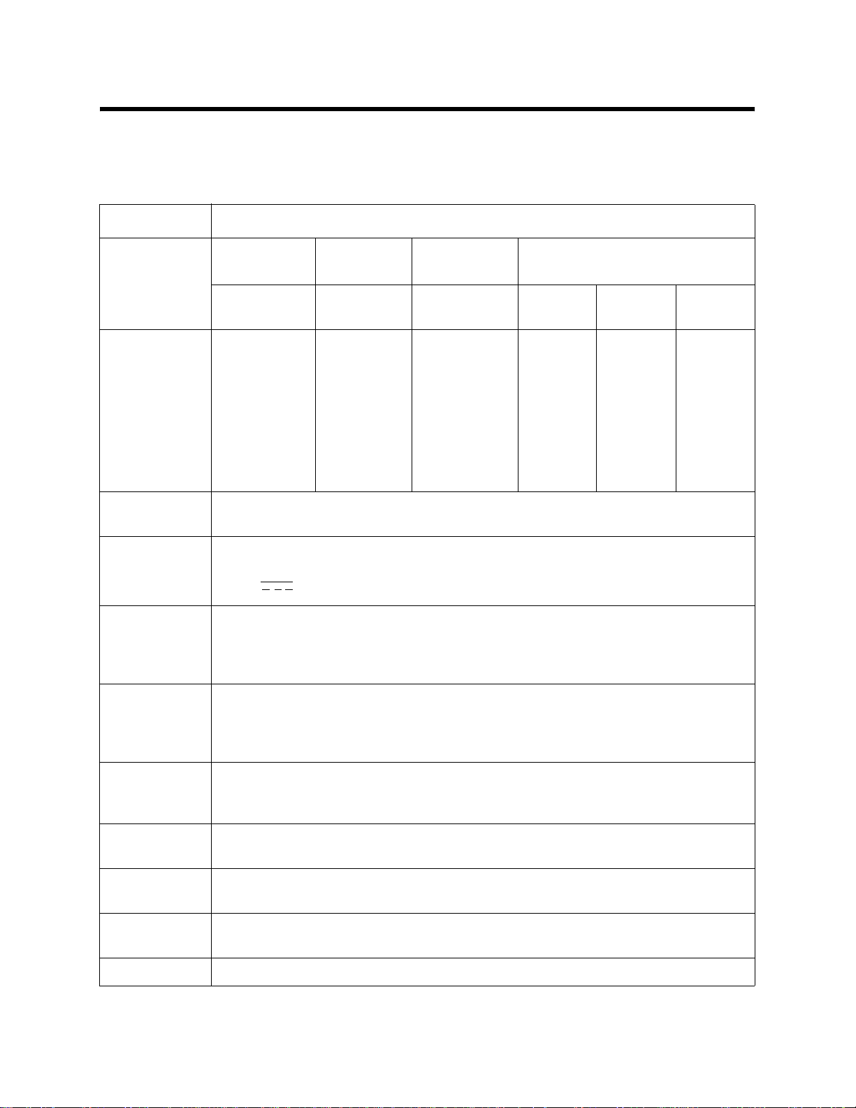
Specifications
Table 1 lists specifications for the Digester Gas Monitor.
Table 1: Digester Gas Monitor Specifications
Description Specification
Detection
Methane
(CH
)
4
Oxygen (O
) Carbon
2
Dioxide (CO
Range
Alarm Points
0 - 100%
volume
Alarm 1:
100% volume
Alarm 2:
100% volume
Alarm 3:
100% volume
0 - 25%
volume
Alarm 1:
4% volume
(increasing)
Alarm 2:
25% volume
(increasing)
0 - 50%
volume
Alarm 1:
50% volume
Alarm 2:
50% volume
Alarm 3:
50% volume
Alarm 3:
25% volume
(increasing)
NOTE: There are different versions of the Digester Gas Monitor. Some versions may
not have all four gas sensors installed.
Input Power 100/115/220V ~ ±10%, 50/60Hz, 1.0/1.0/0.5A
or
24 V ± 10%, 2.5A VDC
Maximum
140 PSI
Compressed
Air Sample
Pressure
)
2
Hydrogen Sulfide (H
0 - 1000
ppm
Alarm 1:
1000 ppm
Alarm 2:
1000 ppm
Alarm 3:
1000 ppm
0 - 3000
ppm
Alarm 1:
3000 ppm
Alarm 2:
3000 ppm
Alarm 3:
3000 ppm
S)
2
0 - 5000
ppm
Alarm 1:
5000 ppm
Alarm 2:
5000 ppm
Alarm 3:
5000 ppm
Minimum
Regulator
Output PSI
No Sample Lines Connected: Regulator output set to 25 PSI
Maximum Recommended Sample Lines Connected: Regulator output set to
45 PSI
Required
Recommended
3.0 SCFH
Sample Flow
Rate
Compressed
63 liters maximum per detection cycle
Air Usage
Construction
Fiberglass/polyester with lexan window (NEMA 4X)
(housing)
Dimensions 24.0 in. H x 24.0 in. W x 10.0 in. D
(61.0 cm H x 61.0 cm W x 25.4 cm D)
Weight 45 lbs. (including horn/strobe)
Digester Gas Monitor Operator’s Manual Specifi cations • 3
Page 10
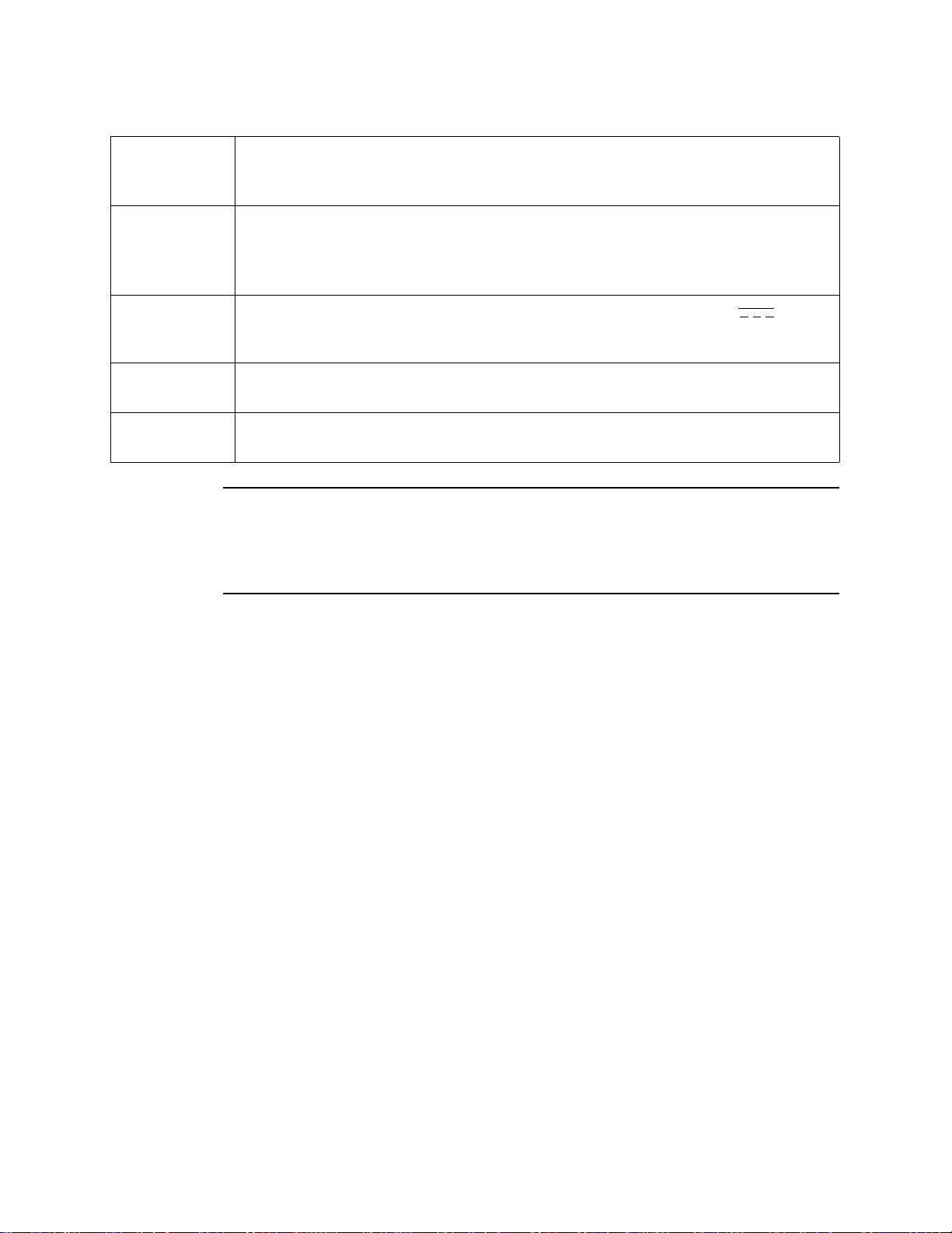
Table 1: Digester Gas Monitor Specifications
Environmental
Conditions
• For indoor or outdoor locations (Type 4X)
• 0°C to 40°C (32°F to 104°F) max. ambient
• Maximum humidity of 95% relative
User Controls • Reset switch
• Control switches: ESCAPE, UP/YES, DOWN /NO, and ENTER
• Regulator output knob
•H
S Dilution Air and H2S Dilution Sample flowmeter valves
2
Relays
• Relay contacts rated for 10A @ 115/220V~ resistive or 10A @ 30V
resistive
• SPDT, Form C (common, normally open, and normally closed contacts)
Standard
Operator’s manual (this document)
Accessory
Optional
Horn/strobe
Accessory
WARNING: When using the Digester Gas Monitor, you must follow the instructions
and warnings in this manual to assure proper and safe operation of the
Digester Gas Monitor and to minimize the risk of personal injury. Be sure
to maintain and calibrate the Digester Gas Monitor as described in this
manual.
4 • Specifications Digester Gas Monitor Operator’s Manual
Page 11
Chapter 2: Description
,
Overview
This chapter describes the Digester Gas Monitor’s external and internal components.
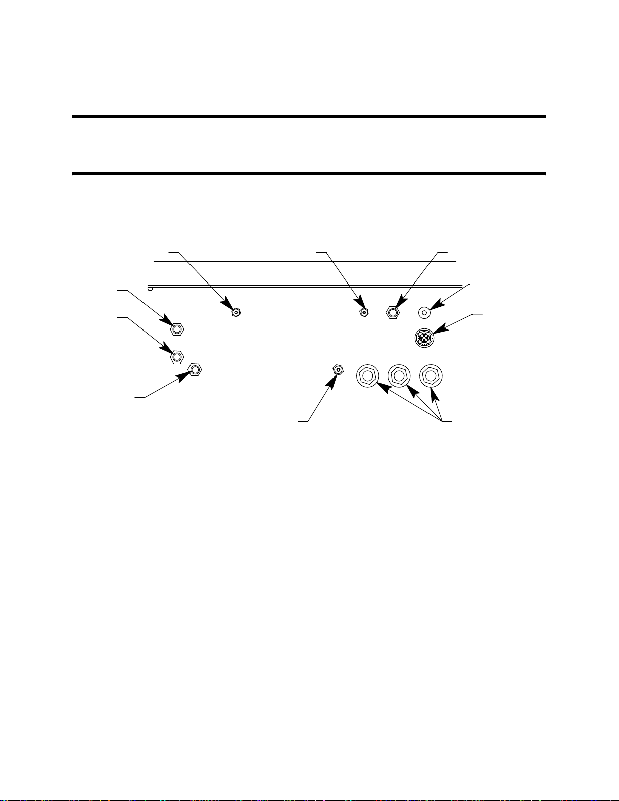
External Description
This section describes the housing and all external components of the Digester Gas
Monitor. For the purposes of this description, the housing door is considered the front of
the monitor.
BlowBackExhaust Calibration Gas Inlet
Dryer
Exhaust
Digester
Sample
Compressed
Air Inlet
Figure 1: External Component Location
Housing
The Digester Gas Monitor’s fiberglass housing is weather- and corrosion-resistant. It is
suitable for installation where general purpose equipment is in use. The housing door is
hinged on the left side and is secured by two latches on the right side. The LCD display,
status LEDs, and flowmeters are visible through the window in the housing door. Four
mounting feet are attached to the back of the housing (one at each corner). The mounting
feet allow you to install the housing to a vertical surface. These mounting feet are not
installed as shipped from the factory (see “Mounting the Digester Gas Monitor” on page 22
for instructions to install the mounting feet). Three conduit hubs on the bottom of the
housing are for external wiring connec ti ons .
FreshAir Inlet
Reset Switch
Push Button
Buzzer
Conduit Hub, 3/4"Aspirator/Sample, Exhaust
Reset Switch
The reset switch is on the bottom right of the housing in front of the buzzer. The reset
switch serves four functions:
• Resets the alarm circuits for “latched” alarms after an alarm 1, alarm 2, or alarm 3
condition passes.
You can set each channel for latched or self-resetting alarms in the Configuration
Menu. See “Viewing and Changing Channel Parameters” on page 51 for more
information.
Digester Gas Monitor Operator’s Manual Overview • 5
Page 12

• Silences the buzzer during an alarm 1, alarm 2, or alarm 3 condition if the alarm
buzzer silence parameter in the Global Menu is set to CAN SILENCE BUZZER. See
“Viewing and Changing Global Parameters” on page 47 for more information on
setting the silence feature.
• Silences and resets the optional horn/strobe during an alarm 1, alarm 2, or alarm 3
condition if the strobe alarm setting parameters are set to Resettable STROBE in the
Configuration Menu. See “Viewing and Changing Channel Parameters” on page 51
for more information on setting the strobe alarm setting parameters.
• Silences the buzzer and optional horn/strobe if the fail silence parameter in the Global
Menu is set to CAN SILENCE FAIL. See “Chapter 5: Global Menu” on page 47 for
instructions to change this parameter.
• Displays and resets the minimum and maximum gas concentration values detected.
Buzzer
The buzzer is on the bottom right of the housing, behind the reset switch. The buzzer
sounds an audible alarm to warn you of gas alarms and instrument failures.
Inlet and Exhaust Fittings
There are a total of 7 fittings on the bottom of the Digester Gas Monitor housing.
Fresh Air Inlet
The fresh air inlet is a compression fitting and is located just to the left of the reset switch.
It accepts 1/4 inch OD rigid metal or rigid plastic tubing. The tubing connected to this inlet
needs to be routed to a fresh air environment.
Calibration Gas Inlet
The calibration gas inlet is a hose barb fitting and is located just to the left of the fresh air
inlet. It accepts 3/16 inch ID flexible tubing and is used to connect a calibration cylinder to
the Digester Gas Monitor during a calibration.
Blow Back Exhaust
The blow back exhaust fitting is a hose barb fitting and is located near the front left of the
Digester Gas Monitor’s bottom panel. This fitting allows debris removed during the blow
back procedure to be expelled. It accepts 3/16 inch ID flexible tubing.
Dryer Exhaust
The dryer exhaust fitting is a compression fitting and is located along the left side of the
Digester Gas Monitor’s bottom panel. It accepts 1/4 inch OD rigid metal or rigid plastic
tubing.
Digester Sample
The digester sample fitting is a compression fitting and is located below the dryer exhaust
fitting. A 1/4 inch OD tube must be connected to this fitting and routed to the area to be
sampled.
Compressed Air Inlet
The compressed air inlet fitting is a compression fitting and is located below and to the
right of the digester sample fitting and is used to connect an air compressor or a tank of
compressed air. It accepts 1/4 inch OD rigid metal or rigid plastic tubing.
6 • External Description Digester Gas Monitor Operator’s Manual
Page 13

Compressed Air Filter/Water Trap
The compressed air filter/water trap is supplied with the Digester Gas Monitor to protect
the Digester from impurities in the compressed air line. The filter is not factory installed
and must be installed by the user. See “Making Fitting Connections” on page 28 for
installation instructions.
Aspirator/Sample Exhaust
The aspirator/sample exhaust fitting is a hose barb fitting and is located just to the left of
the conduit hubs. It accepts 1/4 inch ID flexible tubing.
Digester Gas Monitor Operator’s Manual External Descr iption • 7
Page 14
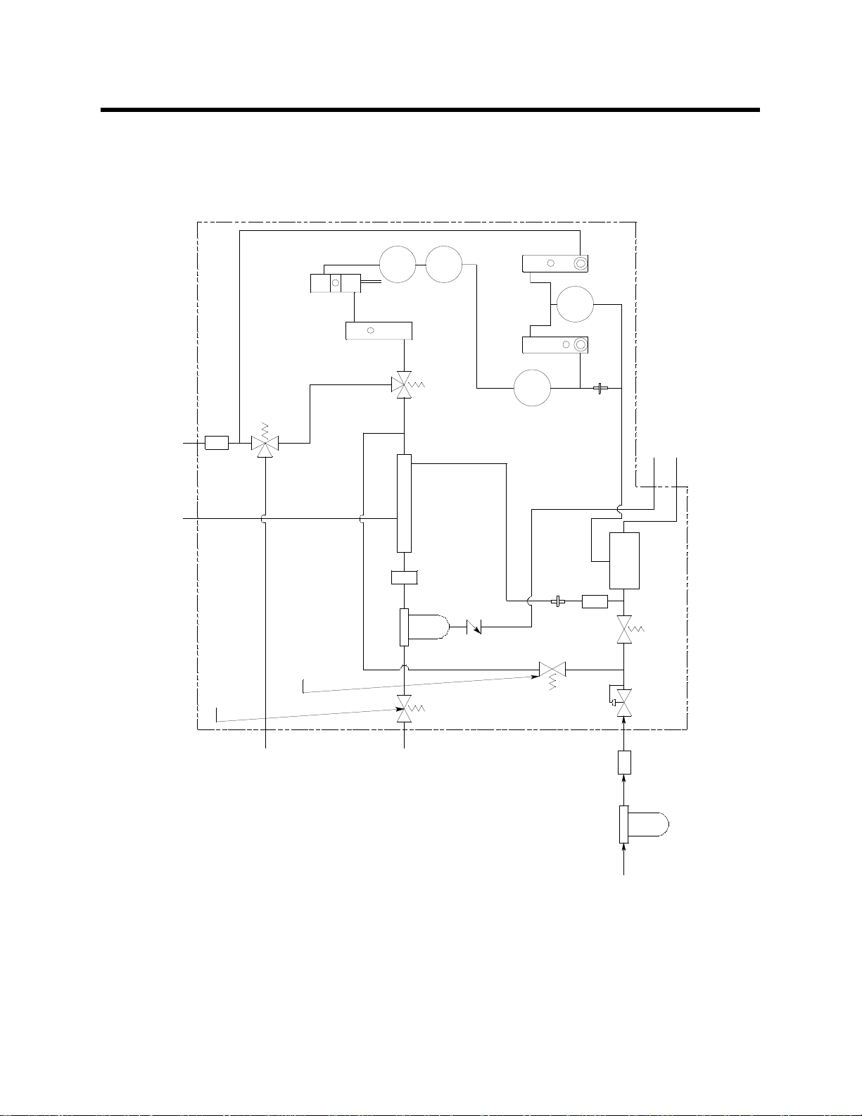
Internal Description
This section describes the internal components of the Digester Gas Monitor. A flow
diagram is shown in Figure 2 and an internal component location is shown in Figure 3.
CH4
ChemTech
Flow Switch
0-5 SCFH
Flow Meter
3-Way S olenoid V al ve B
De-Energized:FreshAir
Particle
Filter
Fresh A i r In
Dryer Exhaust
2-Way S olenoid V al ve E
De-Energized: Normal Op.
Energized:Cal Gas
Wate r T rap
2-W ay Solenoi d Val ve D
De-Energized: Normal Op.
Energized: Blow Back
Energized:BlowBack
O2
De-Energized: Valve B
3-Way S ol enoid Val v e A
Dryer
Filter
Acropak
Dilution
0-2 SCFH
Flow Meter
7:1
H2S
Dilution
Sample
Flow Meter
0-0.5 SCFH
CO2
Energized:Sample
Restrictor
Restrictor
Valve
Check
Filter
Oil Mist
Blowback Exhaust
Aspirator Exhaust
Aspirator
Energized: Aspirator On
2-Way S olenoid V al ve C
De-Energized: Aspirator Off
Regulator
Cal
Gas
Fitting
Sample
Digester
Trap, Field
Filter/Water
Compressed Air
Air InFitting
Installed
Air Source Compressed
Compressed
Figure 2: Flow Diagram
8 • Internal Description Digester Gas Monitor Operator’s Manual
Page 15
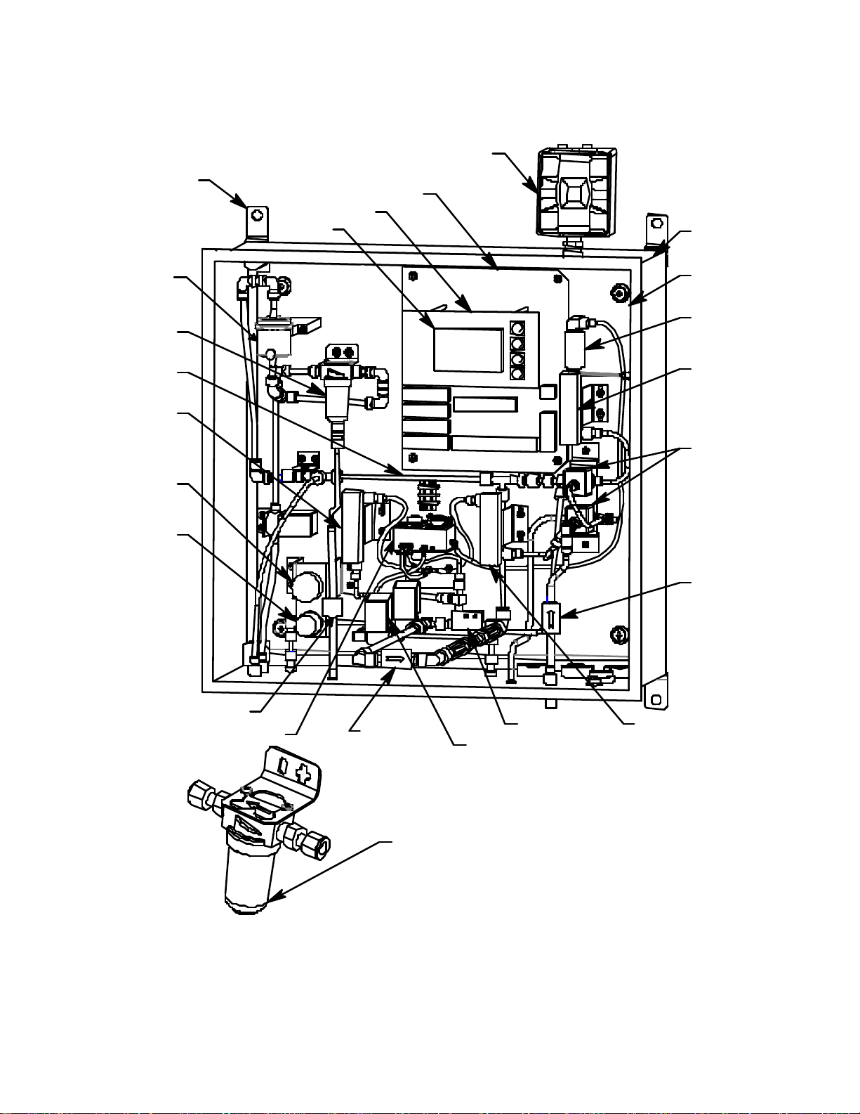
H
Mounting
Fo o t, 4X
Horn/Strobe
(Optional)
Main PCB
DisplayPCB
LCD
Housing
Hydrophobic
Filter
Water Trap
Dryer
Flow Me ter,
H2S Dilution
Sample,
.05 - .5 SCFH
Pressure
Gauge
Regulator
Mounting
Plate
Flow
Switch
Flow Me te r,
Flo w to
Sensors,
0. 6 - 5 S CF
Solenoid
Valve,
3 way
Filter,
Particle
Check V alv e
Flow Bl ock withSensors
Oil Mist Filter
Sol enoid V al ve, 2 W ay, 3X
Compressed Air Filter/WaterT rap
instal led. Locationto be determi ned at i nstall at ion.
Aspirator, Air-Vac
*F ilter i s user
Fl o w Met er,
H2S Dilution Air,
0. 2 - 2.0 SCFH
Figure 3: Digester Gas Monitor Component Location
Digester Gas Monitor Operator’s Manual Internal Description • 9
Page 16
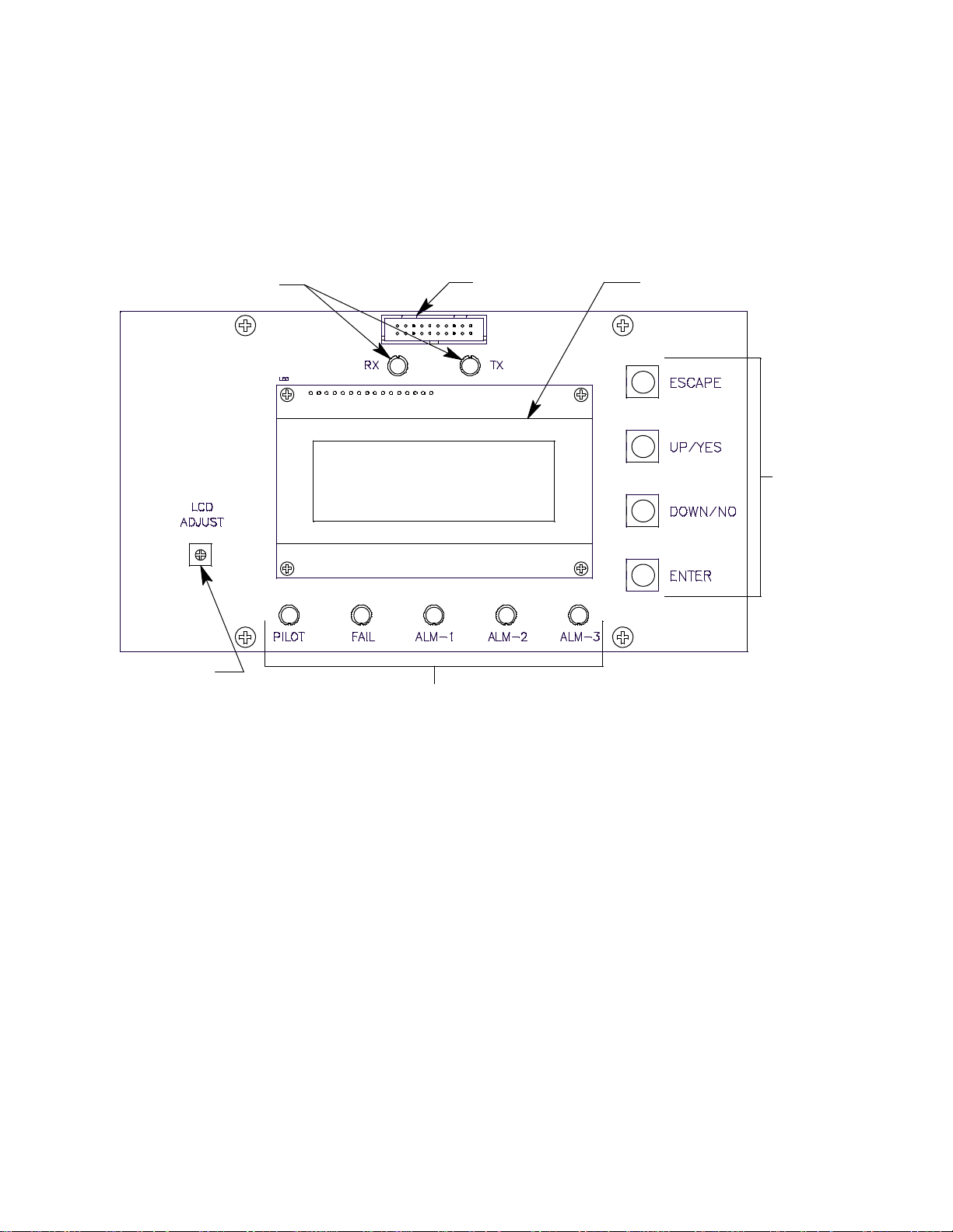
Display PCB
s
The display PCB (printed circuit board) is mounted to the power supply mounting plate
which is in turn mounted to the main PCB. The power supply mounting plate and main
PCB are described below. The display PCB includes the LCD display, the LCD contrast
adjust pot, the status LEDs, and the control switches. It is connected to the main PCB by
the display cable which is a 20 conductor ribbon cable assembly. The display cable
connects to a rectangular connector on the top edge of the display PCB and to the same
type of connector labelled “FRONT PANEL” on the top edge of the main PCB.
Status LEDs
Connector
LCD DisplayDisplay Cable
Control
Switche
LCD Contrast
Adjust Pot
Status LEDs
Figure 4: Display PCB Component Location
LCD Display
The four line display indicates gas readings and shows messages, settings, and other
data when you are operating the various selection menus and operating modes.
LCD Contrast Adjust Pot
The LCD contrast adjust pot is located to the left of the LCD. If the LCD contrast is too
dark or too light to read easily, use a small phillips screwdriver to adjust it until you can
easily read the LCD.
Status LEDs
The Digester Gas Monitor includes seven status LEDs that indicate the current status of
the monitor: the RX & TX LEDs, the pilot LED, the fail LED, the alarm 1 LED, the alarm 2
LED, and the alarm 3 LED (see Figure 4).
• RX & TX LEDs
These LED’s indicate data is being received (RX) and transmitted (TX) when the
Digester Gas Monitor’s Modbus output is operating.
•Pilot LED
The PILOT LED is on when the Digester Gas Monitor is receiving incoming power,
10 • Internal Description Digester Gas Monitor Operator’s Manual
Page 17

either AC or DC power.
• Fail LED
The fail LED turns on when the Digester Gas Monitor is experiencing a fail condition,
including a flow fail. See “Fail Condition” on page 44 and “Flow Fail Condition” on
page 44 for a description of these conditions.
•Alarm 1 LED
The alarm 1 LED is on when the Digester Gas Monitor is experiencing an alarm 1
condition.
•Alarm 2 LED
The alarm 2 LED is on when the Digester Gas Monitor is experiencing an alarm 2
condition.
•Alarm 3 LED
The alarm 3 LED is on when the Digester Gas Monitor is experiencing an alarm 3
condition.
Control Switches
The Digester Gas Monitor includes four push button control switches that allow you to
enter the selection menus and Calibration Mode, navigate through the menus and
Calibration Mode, update instrument and channel parameter settings, and save changes
to the settings. The control switches, listed in Table 2, are to the right of the LCD display
(see Figure 4).
Table 2: Digester Gas Monitor Control Switch Functions
Button Function
ESCAPE • Moves backward through the menu and mode screens
• Aborts operations
• Cancels changes you make in the menus
• Enters the Configuration Menu (press with ENTER button)
• Enters the Global Menu (press with the UP/YES button)
UP (YES) • Initiates an operation or proceeds to the next screen when a yes/
no question is asked on a screen
• Changes the displayed setting
• Enters the Global Menu (press with ESCAPE) button
• Enters the Calibration Mode (press with ENTER button)
DOWN (NO) • Cancels an operation or sequence when a yes/no question is
asked on a screen
• Changes the displayed setting
• Enters the Modbus Menu (press with ENTER button)
ENTER • Saves changes you make in the menu and mode screens
• Accepts the displayed parameter setting
• Enters the Configuration Menu (press with ESCAPE button)
• Enters Calibration Mode (press with UP/YES button)
• Enters the Modbus Menu (press with DOWN/NO button)
• Initiates a manual detection cycle
Digester Gas Monitor Operator’s Manual Internal Descr iption • 11
Page 18
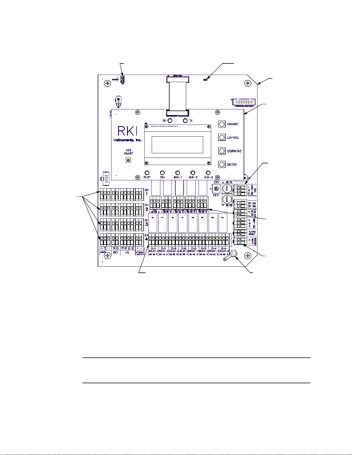
Main PCB
m
p
This section describes the components of the main PCB.
Strobe Te rminal Stri p
TerminationJumper
Main PCB
Control PCB
AC In
Termi nal Stri
Detector/
Transmi tter
Termi nal
Strips
Common/
Channel Alar
Term i nal Strip
Control ler
Term i nal Strip
Channel A larm Terminal Strip
Figure 5: Main PCB Component Location
Terminal Strips
The Digester Gas Monitor includes 9 terminal strips for wiring connections. See “Wiring
the Digester Gas Monitor” on page 23 for detailed wiring procedures.
• Strobe Terminal Strip
The strobe terminal strip is a 2-point terminal strip located in the upper left corner of
the main PCB. When the optional horn/strobe is ordered with a Digester Gas Monitor,
the strobe terminal strip is used to wire the horn/strobe.
CAUTION: The strobe terminals are intended for use with the RKI supplied optional
horn/strobe. Consult RKI Instruments, Inc. before attempting to use these
terminals for any other alarm device.
GroundStud
• Detector/Transmitter Terminal Strips
Four detector/transmitter terminal strips are located along the bottom left side of the
12 • Internal Description Digester Gas Monitor Operator’s Manual
Page 19

main PCB (see Figure 5 on page 12). These four 11-point terminal strips facilitate
wiring connections to the detectors. They also provide terminals to connect a
recording device to a 4 to 20 mA output for each channel. The top terminal strip is for
channel 1 connections and each subsequent strip is used for the next channel with the
bottom terminal strip being for channel 4 connections. The Digester Gas Monitor
detectors are factory wired to the terminal strips.
• Channel Alarm Terminal Strip
A channel alarm terminal strip is located to the right of the channel 4
detector/transmitter terminal strip (see Figure 5 on page 12). This 24-point terminal
strip facilitates wiring external alarm devices (horn, light, etc.) to relay contacts that
are field configurable for alarm levels and operation and are controlled by individual
channels. The contacts are labelled NO (normally open), NC (normally closed),
and C (common). See “Viewing and Changing Global Parameters” on page 47 and
“Viewing and Changing Channel Parameters” on page 51 for instructions to configure
the operation of these contacts.
• Common/Channel Alarm Terminal Strip
The common/channel alarm terminal strip is located in approximately the middle of the
main PCB above the channel alarm terminal strip. The terminals for relays A, B, C,
and D are factory wired and are not available for customer use. Only the fail relay
terminals are available for customer use. The contacts are labelled NO (normally
open), NC (normally closed), and C (common).
• Controller Terminal Strip
The 9-point controller terminal strip is along the lower right side of the main PCB (see
Figure 5 on page 12). The controller terminal strip facilitates various internal and
external wiring connections. Table 3 lists the function of each terminal.
T able 3: Terminal Assignments for the Controller Terminal Strip
Terminal Connects to:
DP SW
Flow switch (factory wired)
DP SW
EXT DC/24V BATT +
EXT DC/24V BATT -
+ connection from 24 VDC power source
- connection from 24 VDC power source
1
(or 24 V backup battery)
1
(or 24 V backup battery)
RS-485 A
RS-485 B Allow connection of the Digester Gas Monitor to a Modbus network
RS-485 C
Alarm Reset
Alarm Reset
Reset Switch Terminals (factory wired)
Alarm Buzzer + Buzzer + connection (factory wired)
1
1
Alarm Buzzer - Buzzer - connection (factory wired)
1
If 24 VDC is used as primary power source do not make wiring connections to the AC terminal strip.
Digester Gas Monitor Operator’s Manual Internal Descr iption • 13
Page 20
•AC Terminal Strip
The 3-point AC terminal strip is located above the controller terminal strip (see
Figure 5 on page 12). The AC terminal strip facilitates wiring connections to the AC
power source.
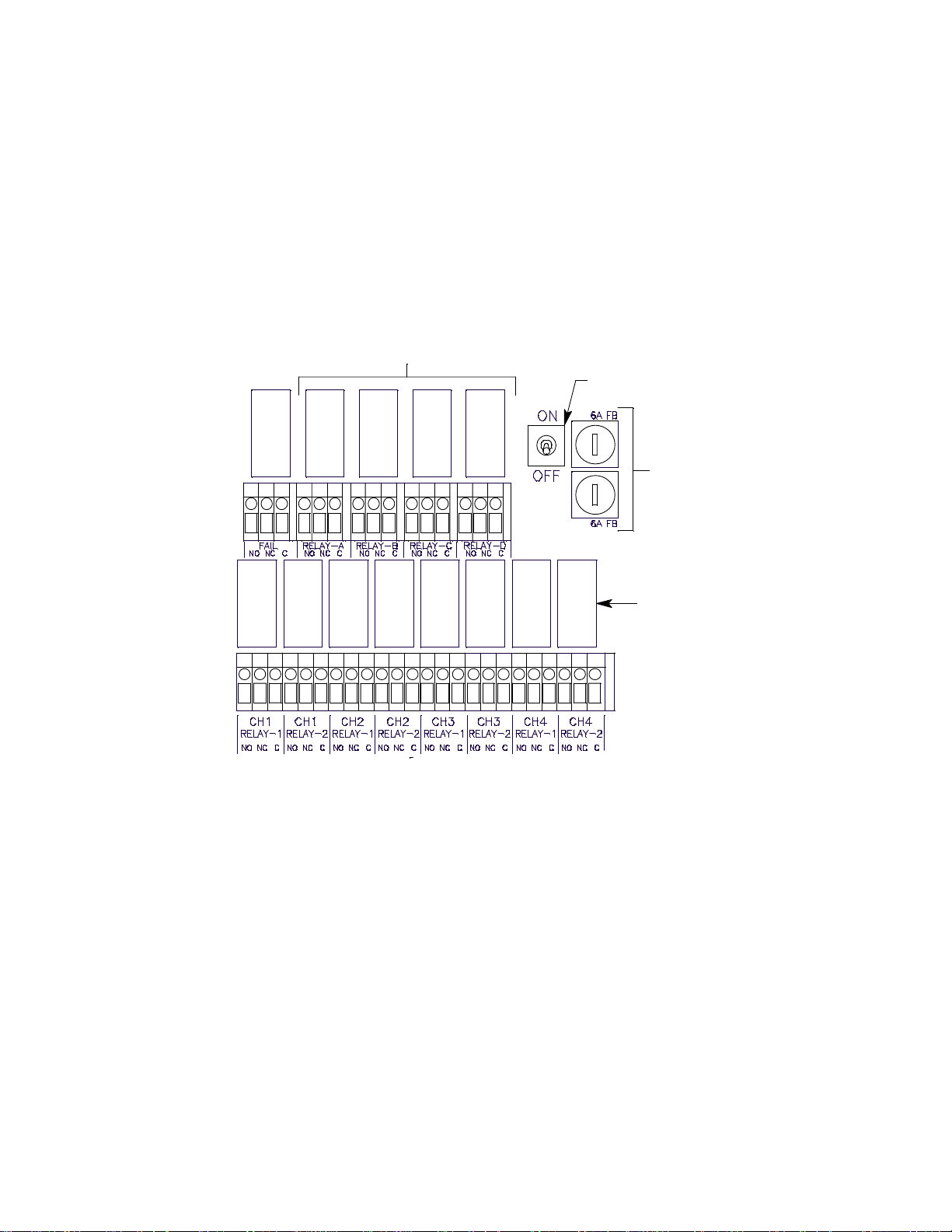
Relays
The Digester Gas Monitor includes eight channel relays and one common fail relay. It also
includes four common/channel relays which are factory set for operational use of the
Digester Gas Monitor. All the relays have single-pole double-throw (SPDT) contacts, also
known as form C contacts, and are rated for 10 amps at 1 15 VAC (resistive). The contacts
are available at the channel alarm terminal strip and are labelled NO (normally open), NC
(normally closed), and C (common).
Not Available for Customer Use
Power Switch
Fail
Relay
Relay
A
Relay
B
Relay
C
Relay
D
AC Fuses
CH 1
Relay
1
CH 1
Relay
2
CH 2
Relay
1
CH 2
Relay
2
CH 3
Relay
1
CH 3
Relay
2
Relay
CH 4
1
CH 4
Relay
2
Channel
Relays
Figure 6: Digester Gas Monitor Relay Allocation
Channel Relays & Fail Relay
The eight channel relays are above the channel alarm terminal strip (see Figure 5 on
page 12 and Figure 6 on page 14). These relays are dedicated to specific channels.
Figure 6 illustrates the allocation of the channel relays.
The fail relay is located above the channel relays. The fail relay is a common relay.
Common/Channel Relays
The four common/channel relays, relays A, B, C, and D, are above the common/channel
alarm terminal strip (see Figure 5 on page 12 and Figure 6 on page 14). These relays are
used in the operation of the Digester Gas Monitor and are not available for customer use.
Termination Jumper
A two pin header with a termination jumper installed is located near the top edge of the
main PCB to the right of the display cable connector. It is labelled “RS-485 Line
Terminator” on the PCB silkscreen. The jumper has no function unless the Digester Gas
Monitor is wired into a Modbus installation. See “Chapter 9: RS-485 Modbus Output” on
14 • Internal Description Digester Gas Monitor Operator’s Manual
Page 21

page 68 for instructions to use the Digester Gas Monitor in a Modbus system.
Ground Stud
The threaded ground stud is used for making connections to earth ground. It is located in
the lower right corner of the main PCB and is connected through the main PCB to the G
(ground) terminal on the AC terminal strip. It is also connected to each conduit hub with a
wire. A kep nut on the stud may be removed for installation of one or more user supplied
lugs to make wiring connections to earth ground. This stud is typically used to connect the
shield drain wire of shielded cable to earth ground at the Digester Gas Monitor.
Power Switch
The power switch is between the common/channel relays and the fuses (see Figure 5 on
page 12 and Figure 6 on page 14). The power switch turns the incoming AC power source
on and off at the Digester Gas Monitor. When the switch is up, the power is on.
Power Supply
The power supply is mounted to the power supply mounting plate which is located behind
the display PCB. The power supply mounting plate is mounted to the main PCB with four
standoffs. The power supply receives AC power from the external power source and
converts it to a DC voltage that is usable by the Digester Gas Monitor circuitry. A
polycarbonate cover prevents accidental contact with the AC terminals on the power
supply.
AC & DC Circuit Protection
Two AC fuses are used in the Digester Gas Monitor. The two fuses are located on the right
side of main PCB, between the power switch and the AC in terminal strip (see Figure 6 on
page 14). They cut off the incoming AC power in the event of a short circuit or other
electrical fault which causes a high current draw in the Digester Gas Monitor. They are
housed in vertical fuse holders and are held in each holder by a quarter turn cover. They
are fast blow fuses rated at 6 A, 250 V.
A polyswitch is used to protect the DC power input. It is located on the right side of the
main PCB above the AC fuses and is labelled on the PCB silkscreen as PS9. In the event
of a short circuit or other electrical fault which causes a high current draw in the Digester
Gas Monitor, the polyswitch will interrupt the DC power if the unit is powered from DC.
When the fault situation is corrected, the polyswitch resets and the unit will continue to
operate. The polyswitch is not user serviceable.
Regulator and Gauge
The regulator and gauge are located in the lower left corner of the Digester Gas Monitor
housing. The regulator’s maximum allowable inlet pressure is 300 PSI. A gauge above the
regulator indicates the output pressure (between 5 and 50 PSI). The output pressure, and
system flow, can be adjusted using the knob on the front of the regulator. The system flow
rises or falls as the output pressure is increased or decreased.
Flow Switch
The flow switch is located in the upper right corner of the Digester Gas Monitor housing.
The flow switch monitors the flow to the sensors and actuates if the flow rate goes below
1.6 SCFH.
Flow Block
The flow block is located in the center of the Digester Gas Monitor and is designed to
accept the gas sensors and route sample to each sensor. The methane, oxygen, and CO
Digester Gas Monitor Operator’s Manual Internal Descr iption • 15
2
Page 22

sensors are retained in the flow block by brackets. The H2S sensor is retained by the Oring compression force of the O-rings it is inserted past. When viewed from the front of the
Digester Gas Monitor, the methane sensor is in the front right corner, the H
the front left corner, the oxygen sensor is in the back right corner, and the CO
S sensor i s in
2
sensor is in
2
the back left corner.
Sensors
Infrared Methane (CH4) Sensor
The IR CH
sensor is an infrared type plug-in detector. The IR CH4 sensor is installed in
4
the front right corner of the flow block when viewing the flow block from the front of the
Digester Gas Monitor. A small preamp circuit board with a 4-wire cable mates to the IR
CH
sensor and retains it in the flow block. The cable is wired to the main PCB. The
4
preamp circuit board allows you to replace the sensor without disconnecting the wiring.
Oxygen (O
) Sensor
2
The oxygen sensor is installed in the right back corner of the flow block when viewing the
flow block from the front of the Digester Gas Monitor. The oxygen cell is protected within
the sensor assembly. Through a series of chemical and electronic reactions, the oxygen
cell produces a millivolt output that is proportional to the detection range of the Digester
Gas Monitor. The leads extending from the sensor terminate in a connector that leads to
the main PCB. The connector allows the sensor to be replaced without disconnecting the
wiring.
Carbon Dioxide (CO
The CO
sensor is an infrared type plug-in detector. The CO2 sensor is installed in the
2
) Sensor
2
back left corner of the flow block when viewing the flow block from the front of the Digester
Gas Monitor. A small preamp circuit board with a 4-wire cable mates to the CO
sensor
2
and retains it in the flow block. The cable is wired to the main PCB. The preamp circuit
board allows you to replace the sensor without disconnecting the wiring.
Hydrogen Sulfide (H
The hydrogen sulfide sensor is a plug-in sensor that plugs into the back of the H
S) Sensor
2
S
2
preamp. The hydrogen sulfide sensor is installed in the front left corner of the flow block
when viewing the flow block from the front of the Digester Gas Monitor. The sensor and
preamp are retained in the flow block by two screws.
Through a series of chemical and electronic reactions, the H
S sensor produces a millivolt
2
output that is proportional to the detection range of the Digester Gas Monitor. The wires
extending from the amplifier are connected to the main PCB.
Flowmeters
Three flowmeters are part of the Digester Gas Monitor’s flow system.
Flow to Sensors Flowmeter
The Flow to Sensors flowmeter is located along the right side of the Digester Gas
Monitor’s flow system and indicates the flow rate being applied to the sensors. This flow
should always be 3.0 SCFH.
H
S Dilution Sample Flowmeter
2
The H
Monitor’s flow system and indicates the sample flow rate to the H
16 • Internal Description Digester Gas Monitor Operator’s Manual
S Dilution Sample flowmeter is located in the middle left of the Digester Gas
2
S sensor. The
2
Page 23

appropriate flow rate depends on the full scale range of the H2S sensor. See “Adjusting
the Flow Rates” on page 33 for more information.
S Dilution Air Flowmeter
H
2
The H2S Dilution Air flowmeter is located in the middle right of the Digester Gas Monitor’s
flow system and indicates the fresh air flow rate to the H
rate depends on the full scale range of the H
page 33 for more information.
S sensor. See “Adjusting the Flow Rates” on
2
S sensor. The appropriate flow
2
Hydrophobic Filter
The hydrophobic filter is located in the upper left corner of the Digester Gas Monitor
housing and prevents water from entering the flow system through the sample inlet that
may have gotten past the water trap.
Water Trap
The water trap is located in the upper left corner of the Digester Gas Monitor housing. It is
slightly below and to the right of the hydrophobic filter. The water trap prevents water from
entering the flow system through the sample inlet. During the blowback procedure, the
water trap is emptied of its contents.
Dryer
The dryer is located in the center of the Digester Gas Monitor and removes any excess
humidity in the sample before the sample enters the flow chamber.
Solenoid Valves
There are five solenoid valves located throughout the Digester Gas Monitor’s flow system.
They control the direction of the flow. They are controlled by the Digester Gas Monitor’s
software and are actuated at various stages of the sampling process.
Check Valves
A check valve in the blowback exhaust line prevents fresh air from entering the sample
line through the blowback exhaust line.
Digester Gas Monitor Operator’s Manual Internal Descr iption • 17
Page 24
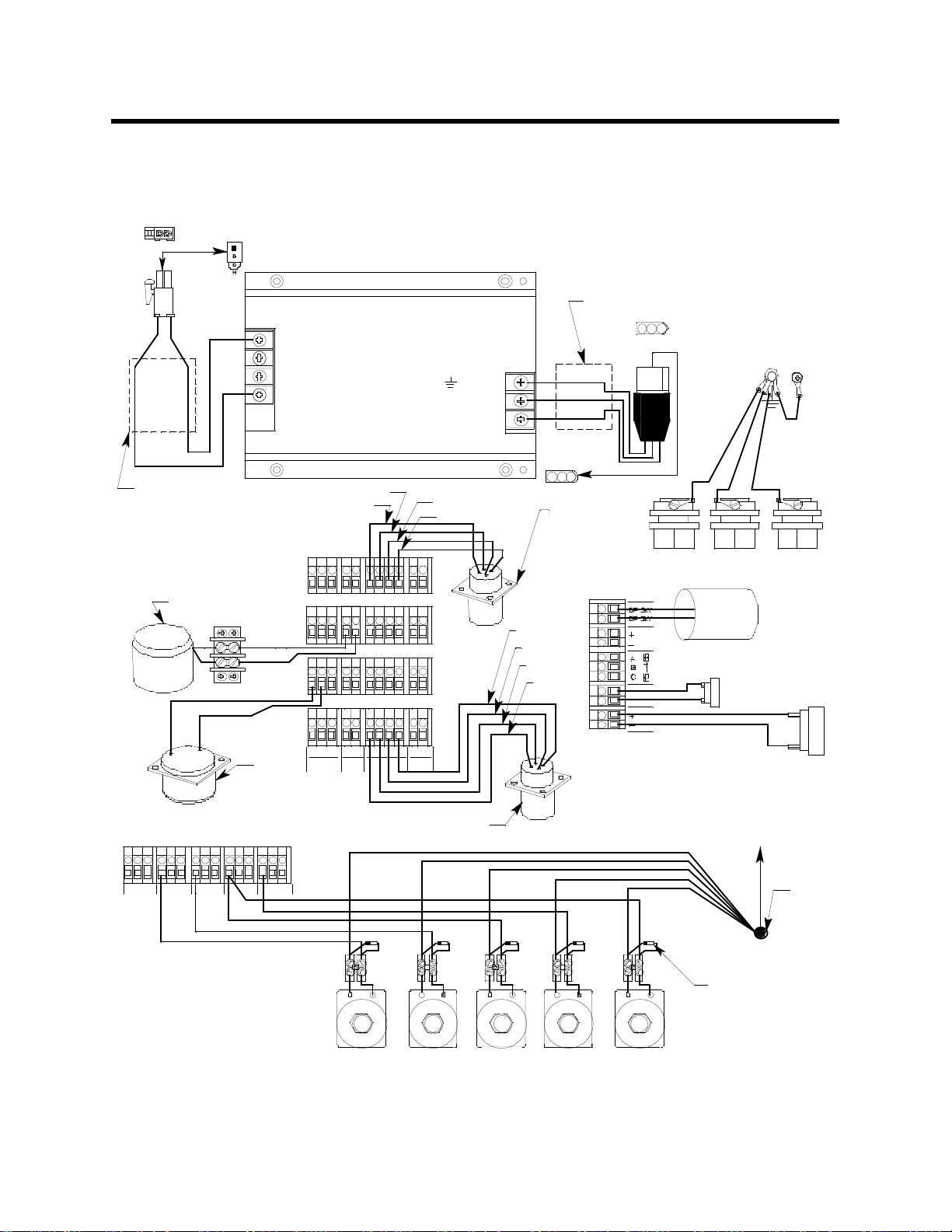
Factory Wiring
The figure below shows the factory wiring. Standard channel assignment is shown. If your
Digester Gas Monitor has less than four sensors, your detector wiring will be slightly
different.
Black
Red
POWER SUPPLY
-V(DC-)
-V(DC-)
+ V (DC+)
+ V (DC+)
(G round )
N(Neutral)
L(Hot)
Wires Twisted
Green
White
Black
Wires Twisted
Detector/Transm itter
Terminal S trips
O2 Sensor
White
Green
Black
Orange
H2S
Sensor
Com mon/C hannel A la rm
Term inal S trip
FA IL
NONC C
RELAY-A
NONC C
RELAY-B
NONC C
RELAY-C
NONC C
RELAY-D
NONC C
White
Red
+S- WG RWGB + -
AMP
4-20m A
LELOXY
OU TPU T
CO2 S ensor
Green
Black
CH
1
CH
2
CH
3
CH
4
CH 4 Sensor
Terminal S trip
Black
Green
White
Red
Controller
ALARM
RESET
EXT DC
24V BATT
ALARM
BU ZZER
Red
Black
Conduit Hubs
Flow
Switch
Reset
Switch
Buzzer
Factory S oldered to
Back of Board
Wire
Nut
Diodes are
A
B
C E
D
shownfor
reference. They
are not u ser
3-W ay
Solenoid
3-W ay
Solenoid
2-W ay
Solenoid
2-W ay
Solenoid
2-W ay
Solenoid
accessible.
Figure 7: Factory Wiring
18 • Factory Wiring Digester Gas Monitor Operator’s Manual
Page 25
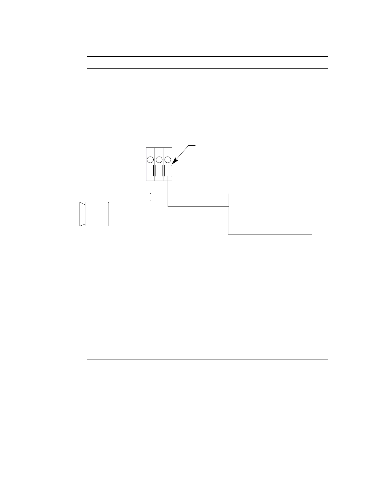
Optional Horn/Strobe
This section describes the optional horn/strobe available for the Digester Gas Monitor. It
can be ordered with the Digester Gas Monitor or it can be ordered at a later date and be
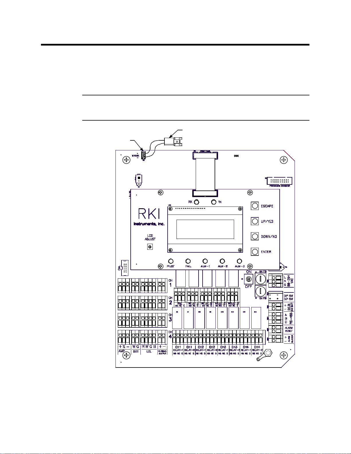
field installed. The horn/strobe is wired to the Strobe Terminal Strip as shown in Figure 8
and Figure 9 below.
NOTE: If the Digester Gas Monitor is not ordered with a horn/strobe, the hole that is
intended for use with the horn/strobe will be plugged and the receptacle will not
be installed.
Strobe Terminal Strip
Strobe Receptacle
Figure 8: Strobe Terminal Strip Location
The Digester Gas Monitor can be ordered with a horn/strobe. This optional horn/strobe
allows the user to have both a strobe and a horn connected to the “Strobe” terminals of the
Digester Gas Monitor. Strobe operation can be programmed in the Global Menu (see
“Chapter 5: Global Menu” on page 47) and in Configuration Mode (see “Chapter 6:
Digester Gas Monitor Operator’s Manual Optional Horn/Strobe • 19
Page 26

Configuration Menu” on page 51).
NOTE: See “Chapter 3: Installation and Start Up” on page 22 for complete Digester Gas
Monitor installation instructions.
CAUTION: Do not adjust the strobe brightness or the horn volume at the horn/strobe, as
this may overload the Digester Gas Monitor strobe control circuit.
Even if the horn/strobe is ordered at the same time as the Digester Gas Monitor, the horn/
strobe does not come factory installed to the Digester Gas Monitor. To install the horn/
strobe:
1. A 3/4 inch NPT nipple is provided for strobe installation. It is not installed on the horn/
strobe and is in its own bag in the shipping box. Guide the cable coming out of the
horn/strobe through the nipple.
2. Install the nipple onto the horn/strobe using an appropriate thread sealing method
such as Teflon tape.
3. If the horn/strobe has been ordered with the Digester Gas Monitor, a conduit hub will
be installed on the top of the housing and will be plugged with a conduit plug. The plug
is included to prevent any debris from falling into the Digester Gas Monitor during
shipment and installation. Remove the conduit plug from the strobe conduit hub.
Continue to step 5.
4. If the horn/strobe has been ordered for a Digester Gas Monitor that is already
installed, a plug is installed in a hole in the top of the housing. Remove this plug and
install the conduit hub that came with the horn/strobe.
A receptacle with 4 inch wires is included with the horn/strobe. Connect the red wire to
the “+” terminal and connect the black wire to the “-” terminal of the Strobe Terminal
Strip as shown in Figure 9.
5. Guide the cable coming from the horn/strobe through the conduit hub at the top right
of the Digester Gas Monitor housing.
NOTE: If there is a plug in the conduit hub, remove it before attempting to install the
horn/strobe.
6. Screw the horn/strobe into the conduit hub at the top right of the Digester Gas Monitor
housing using an appropriate thread sealing method such as Teflon tape. Make sure
the horn/strobe faces forward when installed.
20 • Optional Horn/Strobe Digester Gas Monitor Operator’s Manual
Page 27
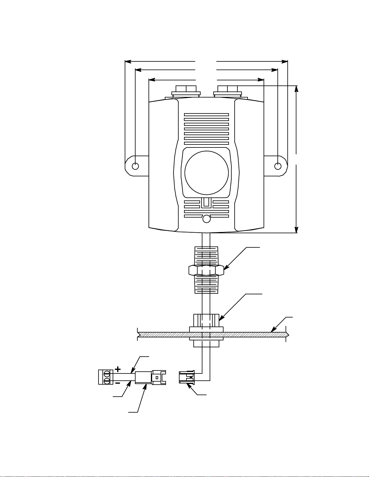
7. Connect the plug coming from the horn/strobe to the receptacle coming from the
S
strobe terminal strip.
6.81
5.97
4.83
6.17
trobe Terminal
Strip
Receptacle
Black
Red
-+
Plug
3/4" NPT Nipple
C onduit Hub
Digester
Housing
Note: Dimensions
Shown in Inches
Figure 9: Horn/Strobe Wiring/Outline and Mounting Dimensions
Digester Gas Monitor Operator’s Manual Optional Horn/Strobe • 21
Page 28
Chapter 3: Installation and Start Up
Overview
This chapter describes procedures to mount the Digester Gas Monitor, make wiring
connections to the monitor, and start up the monitor.
WARNING: Perform all installation and start-up procedures in a known fresh air
environment, an environment free of combustible and toxic gasses and of nor mal
oxygen content. The Digester Gas Monitor is not in operatio n as a gas
monitoring device until the start up procedure is complete.
Mounting the Digester Gas Monitor
Perform the following procedure to install the Digester Gas Monitor at the mounting site.
1. Select the mounting site. When you select the mounting site, consider the following
factors:
• Is an AC or DC power source available?
• Is a vertical surface available to mount the Digester Gas Monitor?
• Is there enough room to open the housing door and make wiring and tubing
connections through the conduit hubs and fittings at the bottom of the housing?
• Are the display screen and status lights visible?
2. Close and latch the housing door.
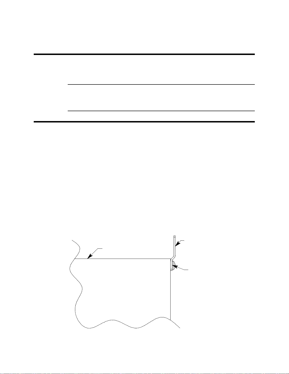
3. The mounting feet for the Digester Gas Monitor are shipped in a separate bag that is
taped to the outside of the housing. Install the mounting feet to each corner on the
back of the housing so that the shortest section of the mounting foot is flush with the
back of the housing and the longest section of the mounting foot is offset away from
the housing. See the figure below.
Long
Housing
Section
Short
Section
Figure 10: Mounting Feet Installation
22 • Overview Digester Gas Monitor Operator’s Manual
Page 29
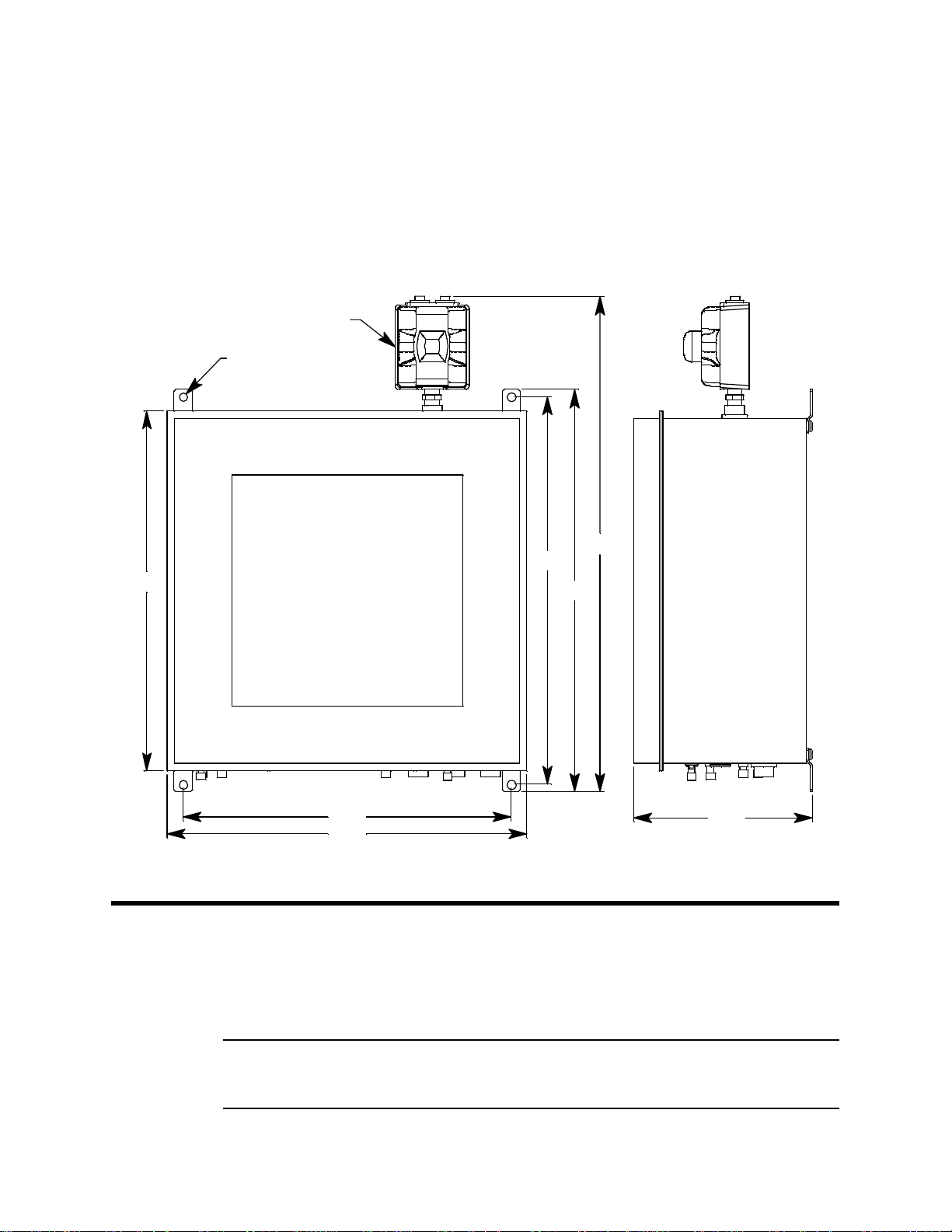
4. Prepare the selected mounting site as required to mount the Digester Gas Monitor. It
should be mounted at eye level (4 1/2 to 5 feet from the floor). Refer to Figure 11 for
the outline and mounting dimensions.
5. Position the monitor on the vertical mounting surface. Use a level to ensure that the
Digester Gas Monitor housing is level in all planes. The flowmeters will not operate
properly if the Digester Gas Monitor is not mounted as shown below and level in all
planes.
6. Insert 1/2 in. screws through the slots in the mounting feet at each corner of the
housing to secure the housing to the mounting surface.
Horn/Strobe (Optional)
Ø.56,4X
25.59
23.75
25.59
Figure 11: Digester Gas Monitor Outline and Mounting Dimensions
Wiring the Digester Gas Monitor
This section describes procedures to connect the AC power source, DC power source,
Modbus wiring (refer to “Wiring the Digester Gas Monitor in a Modbus System” on
page 68), external alarms, and recording devices. See Figure 12 on page 24 for a general
diagram of all external wiring to the Digester Gas Monitor.
34.72
26.89
27.85
12.35
NOTE: User-Installed Compressed Air Filter/
Water T r ap N ot Shown in This View
WARNING: Make all connections to the Digester Gas Monitor before you plug in o r tur n on
the AC or DC power source. Before you make any wiring adjustments, always
verify that all power sources are not live.
Digester Gas Monitor Operator’s Manual Wiring the Digester Gas Monitor • 2 3
Page 30

Buzzer
AC Power
100/115 VAC
50 / 60 Hz
Line (Hot)
Neutral
Ground
24V DC
FlowSwitch
(Factory wired)
Reset S wi tc h
See M odbus W iring
In C hapter9
(Factory wired)
(Factory wired)
220 VAC Wiring
LACN
G
AC InTerminal Strip
NOTE: Line and NeutralareL1and L2 for
ControllerTerminal Strip
DP S W
EXT DC
B
A
C
Power
RS - 485
ALARM
RESET
ALARM
24V BATT
BUZZER
CH 4
RELAY-2
NO NC C
Ala rm Device
Power
Ala rm Device
RELAY-D
NO NC C
RELAY-CFAIL
NO NC CNO NC C
RELAY-B
NO NC C
For Factory Use Only
RELAY-A
Common / Channel AlarmTerminalStrip
NO NC C
Alarm Device, Typical Alarm Wiring Shown
Relay Contac ts Rated For 10 AmpsAt 250 VAC
CH 4
RELAY-1
NO NC C
CH 3
RELAY-2
NO NC C
CH 3
RELAY-1
NO NC CNO NC C
CH 2
RELAY-2
CH 2
RELAY-1
Channel Alarm Terminal Strip
NO NC C
Alarm Devices, Typical Alarm Wiring Shown
CH 1
RELAY-2
NO NC C
CH 1
RELAY-1
NO NC C
Relay Contac ts Rated For 10 Am ps At250VAC
4-2 0 m A
Red
Black
OUTPUT
GBR
LEL
W
Recording Device
500 Ohms Impedance Maximum
GW
Strobe TerminalSt ri p
Optional Horn/Strobe
(typical 1 of 4)
OXY
S
AM P
Detect or / Transmitter TerminalStrip
Figure 12: Digester Gas Monitor External Wiring Diagram
24 • Wiring the Digester Gas Monitor Digester Gas Monitor Operator’s Manual
Page 31

Connecting the AC Power Source
r
z
NOTE: If you are using DC power as the primary power source, go to the next section,
“Connecting the DC Power Source”.
The AC in terminal strip will accept 24 - 14 AWG wire. When selecting wire to connect the
AC power source to the Digester Gas Monitor, be sure to meet the local electrical code.
Also be sure to use an appropriate circuit breaker in the AC line close to the Digester Gas
Monitor that meets the local electrical code.
Perform the following procedure to connect the AC power source to the Digester Gas
Monitor.
WARNING: Verify that the power source is unplugged or turned off before you continue with
this procedure.
1. Turn off or unplug all incoming power to the Digester Gas Monitor.
2. Open the housing door, then place the power switch in the OFF position.
CAUTION: The power switch does not control DC input power.
3. Locate the AC in terminal strip (see Figure 5 on page 12). The terminals are labelled
4. Install an appropriately rated cable bushing or conduit in the right-most conduit hub on
5. Guide the AC power cord or wires in conduit through the right-most conduit hub on the
6. Connect the AC wires to the AC in terminal strip as shown in Figure 13 below.
100/115 VA C Wiring
L
N
G
AC In Terminal Strip
Connecting the DC Power Source
WARNING: Verify that the power source is unplugged or turned off before you continue with
L, N, and G for line, neutral, and ground respectively.
the bottom of the Digester Gas Monitor housing.
bottom of the Digester Gas Monitor housing.
Line (Hot)
Neutral
Earth Ground
this procedure.
AC Power
100/115 VAC
50 / 60 Hz
Figure 13: AC Power Wiring
L
N
G
AC In Terminal Strip
220 VAC Wi ri ng
Earth Ground
L1
L2
AC Powe
220 VAC
50 / 60 H
DC power may be used as a primary power source. It may also be used as a backup
power source with a 24 VDC battery if AC power is the primary power source. If your
Digester Gas Monitor does not include the battery charging feature, you may use a self
contained 24 VDC backup that keeps its batteries charged while AC power is on and
recharges the batteries when AC power returns after a power failure. If your Digester Gas
Monitor includes the battery charging feature, see “Battery Charging (Optional)” on
Digester Gas Monitor Operator’s Manual Wiring the Digester Gas Monitor • 2 5
Page 32

page 39 for a complete description of this feature and what type of battery to use. If DC
r
power is the primary power sour ce , DO NOT connect AC power.
1. Turn off or unplug all incoming power to the Digester Gas Monitor.
2. Open the housing door, then place the power switch in the OFF position.
CAUTION: The power switch does not control DC input power.
3. Locate the DC input power terminals on the controller terminal strip near the lower
right edge of the main PCB (see Figure 5 on page 12). They are labelled EXT DC/24V
BATT+ and EXT DC/24V BATT -.
4. Install an appropriately rated cable bushing or conduit in an unused conduit hub on
the bottom of the Digester Gas Monitor housing.
5. Guide a DC power cord or two wires in conduit through the selected conduit hub on
the bottom of the Digester Gas Monitor housing.
6. Connect the DC power wires to the controller terminal strip as shown in Figure 14
below.
DC Power In Terminals on
Controller Terminal Strip
EXT DC
24 V BATT
Figure 14: DC Power Wiring
NOTE: The Digester Gas Monitor will operate from the DC input down to 18.5 volts. If a
self contained backup battery is used, see its operator’s manual for a description
of its recharging characteristics. If your Digester Gas Monitor includes the battery
charging feature and a backup battery is used, the Digester Gas Monitor will
recharge the battery when AC power has returned after a power failure. See
“Battery Charging (Optional)” on page 39 for a complete description of the battery
charging feature.
DC Powe
24 VDC
RS-485 Modbus Wiring
See “Wiring the Digester Gas Monitor in a Modbus System” on page 68 for wiring
connections to the RS-485 Modbus terminals.
Connecting External Alarms
Before connecting any external alarm devices to the relay contacts, make sure you know
how you want the devices to operate. For example, confirm under what alarm condition
you want a device to turn on or turn off and what channel is going to control the device.
Also make sure that the parameter settings that apply to the relays in the Global Menu and
the Configuration Menu are set so that the desired alarm device operation is obtained.
See “Viewing and Changing Global Parameters” on page 47 and “Viewing and Changing
Channel Parameters” on page 51 for information about the relay parameters.
Perform the following procedure to connect external alarm devices to the Digester Gas
Monitor.
1. Turn off or unplug all incoming power to the Digester Gas Monitor.
26 • Wiring the Digester Gas Monitor Digester Gas Monitor Operator’s Manual
Page 33
2. Open the housing door, then place the power switch in the OFF position.
CAUTION: The power switch does not control DC input power.
3. Locate the applicable alarm terminal strip (see Figure 5 on page 12).
4. Install an appropriately rated cable bushing or conduit in an unused conduit hub on
the bottom of the Digester Gas Monitor.
5. Guide the wiring of the external alarm device through the selected conduit hub on the
bottom of the Digester Gas Monitor housing.
6. Connect the leads from the external alarm device and an external power source to the
selected channel alarm or fail relay contact terminals as shown in Figure 15.
CH 1 RELAY 1
NO NC C
Channel 1,Relay 1 A larm T erminals
From Channel Alarm Terminal Strip
(+) H
(-) N
External Alarm Device
Figure 15: External Alarm Wiring
External
Power Source
7. Repeat step 5 and step 6 for additional external alarm devices.
Connecting Recorders
Perform the following procedure to connect an analog signal recording device to the
Digester Gas Monitor. The output at the recorder output terminals for each channel is a 4 20 mA signal that corresponds to the detection range of the detector connected to that
Digester Gas Monitor channel. Be sure to read the recording device’s operator’s manual
before installation and follow all wiring procedures and recommendations made by the
recording device’s manufacturer.
1. Turn off or unplug incoming power to the Digester Gas Monitor.
2. Open the housing door, then place the power switch in the OFF position.
CAUTION: The power switch does not control DC input power.
3. Locate the recorder output terminals on the right end of the detector/transmitter
terminal strips. See Figure 5 on page 12 to assist you in locating the recorder output
terminals. They are labelled 4 - 20 mA OUTPUT + and 4 - 20 mA OUTPUT -.
4. Install an appropriately rated cable bushing or conduit in an unused conduit hub on
the bottom of the Digester Gas Monitor housing.
5. Guide the wiring from the recording device through the selected conduit hub on the
bottom of the Digester Gas Monitor housing.
Digester Gas Monitor Operator’s Manual Wiring the Digester Gas Monitor • 2 7
Page 34

6. Connect the leads from the recording device to the recorder output terminals of the
4-20 mA
selected active channels as shown in Figure 16 below.
OUTPUT
Figure 16: Recorder Output Wiring
Making Fitting Connections
Compression Fitting Connections
The fresh air inlet, dryer exhaust, digester sample inlet, and compressed air inlet fittings
are all compression fittings with ferrules that accept rigid metal or rigid plastic tubing. The
tube nuts are loosely screwed on and are not tightened completely. Do not tighten the tube
nut until a rigid tube is inserted.
The compression fittings accept 1/4 inch OD rigid metal or rigid plastic tubing. Stainless
steel, Teflon, or polypropylene tubing is recommended.
Recorder Output T erminal s From a
Detector/Transmitter Termi nal Strip,
Typical of 4
4 - 20 mA Input
Recording Device
500 Ohms Impedance
Maximum
NOTE: Rigid metal must be used to connect to the compressed air inlet compression
fitting.
The maximum lengths of tubing that can be connected to each compression fitting, the
recommended size, and the recommended material are outlined in the table below.
Table 4: Compression Fitting Maximum Tubing Lengths
Maximum
Fitting
Fresh Air Inlet 100 • 1/4 inch OD x 3/16 inch ID plastic
Digester Sample
Inlet
Dryer Exhaust* 50 • 1/4 inch OD x 3/16 inch ID plastic
T ubing Length
(ft.)
100 • 1/4 inch OD x 3/16 inch ID plastic
Recommended Tubing Size
• 1/4 inch OD x 0.035 inch wall metal
• 1/4 inch OD x 0.035 inch wall metal
• 1/4 inch OD x 0.035 inch wall metal
Recommended
Tubing Material
Stainless steel,
Teflon, or
polypropylene
Stainless steel,
Teflon, or
polypropylene
Stainless steel,
Teflon, or
polypropylene
28 • Making Fitting Connections Digester Gas Monitor Operator’s Manual
Page 35

Table 4: Compression Fitting Maximum Tubing Lengths
Fitting
Compressed Air
Inlet
Maximum
T ubing Length
(ft.)
Determine
length based
on installation
Recommended Tubing Size
1/4 inch OD tubing rated for pressure
supplied
Recommended
Tubing Material
Stainless steel,
copper, or
aluminum
* It is not necessary to route the dryer exhaust away from the digester, but it may be done if desired.
Compressed Air Inlet Fitting and Compressed Air Filter/Water Trap
1. A filter/water trap must be installed in the compressed air inlet line as close to the
Digester Gas Monitor as possible. The filter/water trap has compression fittings for
connection. The filter/water trap is not factory installed and must be field installed. It is
shipped separately from the Digester Gas Monitor. Rigid metal tubing is
recommended for compressed air inlet fitting connections.
2. If the filter/water trap will be installed where it’s unlikely to be bumped, the metal
tubing is strong enough to support the filter/water trap. If it’s likely that the filter/water
trap will be bumped, it should be mounted to a wall as close to the Digester Gas
Monitor as possible using screws and the filter/water trap’s bracket.
3. Install a short length of 1/4 inch OD rigid metal tubing that will connect the
compressed air inlet fitting to the filter/water trap into the tube nut and ferrules of the
compressed air inlet fitting on the Digester Gas Monitor.
Hold Still (5/8 inch)
Ferrule
Nut (9/16 inch)
1/4 inch OD
rigid metal
tubing
Com pressedAi r Fi t ting
Figure 17: Compressed Air Inlet Fitting Connection
Digester Gas Monitor Operator’s Manual Making Fitt ing Connections • 29
Page 36

4. Before tightening the nut, be sure to hold the fitting still from the outside so it does not
a
d
rotate using a 5/8 inch open-end wrench or an adjustable wrench (see Figure 17).
While holding the fitting still, firmly tighten the nut with a 9/16 inch open-end wrench or
an adjustable wrench so the ferrules crimp onto the sample tubing and make a seal.
5. Connect the other end of the tubing coming from the compressed air inlet fitting to the
filter/water trap exhaust. Be sure that the arrow on the top of the filter/water trap is
facing toward the compressed air inlet fitting. Use a 5/8 inch open-end wrench or an
adjustable wrench to hold the filter/water trap still and use a 9/16 inch open-end
wrench or an adjustable wrench to firmly tighten the nut so the ferrules crimp onto the
tubing and make a seal.
Hold Still(5/8 inch)
1/4inchODrigid metal
tubing from compressed
ir inlet f itting o fDigester
6. Install the desired length of 1/4 inch OD rigid metal tube from the compressed air
source into the tube nut and ferrules on the other side of the filter/water trap. Use a
5/8 inch open-end wrench or an adjustable wrench to hold the filter/water trap still and
use a 9/16 inch open-end wrench or an adjustable wrench to firmly tighten the nut so
the ferrules crimp onto the tubing and mak e a seal .
7. The filter/water trap is self-draining. If the Digester Gas Monitor is not installed in an
area where the water trap can drain onto the ground, install a length of 1/8 inch ID
tubing onto the barb fitting on the bottom of the filter/water trap and route it to a
bucket.
8. The Digester Gas Analyzer uses a maximum of 63 liters of compressed air per cycle
when the maximum allowable tubing lengths are installed. The minimum regulator
output pressure required when no sample lines are installed is 25 PSI. The minimum
regulator output pressure required when the maximum recommended sample line
lengths are installed is 45 PSI. The maximum compressed air supply pressure is 140
PSI. Be sure tha t your compressed air source has sufficient capacity, sufficient
pressure, and be sure that the compressed air sample is clean and/or filtered.
Connect the compressor line to the rigid tubing coming from the compressed air filter/
water trap.
1/4inchODrigi
metal tubing to
compressorline
Nut (9/16 inch)
Figure 18: Compressed Air Filter/Water Trap
30 • Making Fitting Connections Digester Gas Monitor Operator’s Manual
Page 37

Fresh Air Inlet, Dryer Exhaust, and Digester Sample Inlet Fittings
)
)
1. Install the desired length of 1/4 inch OD rigid metal or rigid plastic tube into the tube
nut and ferrules as shown in the figure below. Stainless steel, T eflon, or polypropylene
tubing is recommended.
Hold Still (5/8 inch)
Hold Still (5/8 inch
FerruleFerrule
Dryer Exhaust and
Fresh Air Inlet Fittings
2. Before tightening the nut, be sure to hold the fitting still so it does not rotate using a
5/8 inch open-end wrench or an adjustable wrench. The dryer exhaust and fresh air
inlet fittings will have to be held from the inside of the housing while the sample inlet
fitting will have to held from the outside (see Figure 19). While holding the fitting still,
firmly tighten the nut with a 9/16 inch open-end wrench or an adjustable wrench so the
ferrules crimp onto the sample tubing and make a seal.
3. Route the tubing to the desired area. The fresh air inlet tubing needs to routed to a
fresh air environment while the digester sample inlet needs to be routed to the desired
sampling area.
Hose Barb Connections
Nut (9/16 inch)
1/4 inch OD
ri gi d me tal or
ri gi d plas tic
tubing
Sample Inlet Fitt ing
Figure 19: Compression Fitting Connection
Nut (9/16 inch
1/4 inch OD
ri gid me tal or
ri gid plastic
tubing
1. The blowback exhaust discharges contents from the filters and water trap. It will
contain corrosive gas and particulate or liquid discharge. For this reason, the
blowback exhaust needs to be routed into a container where it may be safely
discharged. Connect up to 20 feet of 3/16 inch ID flexible tube to the blowback
exhaust fitting and route it to a container.
2. Connect up to 100 feet of 1/4 inch ID flexible tube to the aspirator/sample exhaust
fitting and route it to a fresh air area where it can be safely discharged.
Digester Gas Monitor Operator’s Manual Making Fitt ing Connections • 31
Page 38

WARNING: The aspirator/sample exhaust may contain high levels of toxic gases. It is
important to route the exhaust to a fresh air area where there is no danger of it
being inhaled.
St arting Up the Digester Gas Monitor
Perform the following procedure to place the Digester Gas Monitor into normal operation.
NOTE: The following screens illustrate a four-channel Digester Gas Monitor. Depending
on what version of the Digester Gas Monitor you have, your screens may appear
slightly different.
1. Complete the mounting and wiring procedures described earlier in this chapter.
2. Verify that all wiring connections are correct and secure and that the Digester Gas
Monitor’s power switch is in the OFF position.
3. Plug in or turn on the incoming power source (A C or DC).
4. Turn on the power switch if AC power is used as primary power.
5. The following screen appears for a few seconds.
RKI Instruments
Beacon 410
Digester Gas Monitor
6. The Version Screen then appears. It shows the instrument’s hardware and firmware
versions for a few seconds. HW is the hardware version. Main is the main firmware
version. MB is the Modbus firmware version. The version numbers on the bottom line
are the firmware versions loaded for each channel.
VERSION INFO
HW: 0002
Main: D002 MB: 0001
D001 D001 D001 D001
To keep the version information screen on the display longer than a few seconds,
press and hold the ENTER button while it is being displayed. When you release the
ENTER button, the startup sequence will continue.
7. After the Version Screen has been displayed for a few seconds, WARMING UP
appears for each active channel. The warm-up time is counted down in seconds from
60 seconds for each active channel on the far right.
1: Warming Up 60
2: Warming Up 60
3: Warming Up 60
4: Warming Up 60
NOTE: To prevent unwanted alarms during warm up, the alarm circuits are not active
while the WARMING UP message is displayed.
32 • Starting Up the Digester Gas Monitor Digester Gas Monitor Operator’s Manual
Page 39

8. Any unused channels are configured as NOT USED in the Configuration Menu at the
factory. For any unused channels, NOT USED is display ed on the line fo r that
channel. If any channels have been configured as STANDBY in the Configuration
Menu, STANDBY is displayed on the line for that channel. See “Viewing and
Changing Channel Parameters” on page 51 for a description of the NOT USED and
ST ANDBY configurations.
9. Verify that the PILOT light is on. If the PILOT light is not on, see the troubleshooting
guide in “Troubleshooting” on page 79.
10. When the warm- up period is complete, the Digester Gas Monito r ente rs a 60 secon d
standby period. The display will alternate between the fresh air reading and the time
left before the first detection cycle begins. During this initial standby period, you can
perform a calibration if needed. See “Performing a Calibration” on page 63 for
instructions. In addition, you may enter any of the Digester Gas Monitor’s setup
menus during this time.
Standby Mode
# of Samples 0
Next Detection Cycle
in 0D: 0H: 0M: 59S
NOTE: If you enter Calibration Mode or one of the setup menus during the initial 60
second standby period, the 60 second count is paused and resumes once you
exit Calibration Mode or the setup menu.
11. Once the initial 60 second standby period has passed, the Digester Gas Monitor
begins a detection cycle with a pre-sample purge. For more description of the
sampling cycle, see “Detection Cycle” on page 35. During this first cycle, the flow
rates must be set during the sampling period as described in the next section and in
“Detection Cycle” on page 35. If you are unable to set the flow rates during the inital
cycle, a manual cycle must be initiated.
Adjusting the Flow Rates
The flow rates during a detection cycle are factory set but may require adjustment after the
installation of the fresh air inlet, calibration gas inlet, blow back exhaust, digester sample,
and aspirator/sample exhaust lines. In addition, because of differences between the
sample inlet restriction and the calibration inlet restriction, the flow rates may need
adjustment during a calibration. Follow this procedure if you notice that your flow rates are
not correct. Before adjusting flow rates, be sure that all inlet and/or exhaust lines are
connected to the appropriate fitting on the bottom of the housing.
1: METHANE 0 %VOL
2: OXYGEN 20.9 %VOL
3: CO2 0.0 %VOL
4: H2S 0 ppm
If the flow rates need adjustment, they must be set during the sample period of a detection
cycle or during a calibration procedure. If the flow rates need adjustment during
calibration, the flow rates must be set again during the next sample period.
The Flow to Sensors flowmeter should always read 3.0 SCFH. The flow rate value for the
H
S Dilution Sample and H2S Dilution Air flowmeters depend on the detection range of
2
the H
S channel. The table below outlines the flowrate that each flowmeter should read for
2
the available H
Digester Gas Monitor Operator’s Manual Starting Up the Digester Gas Monitor • 33
S detection ranges.
2
Page 40

H
S Range
2
Table 5: Flow Rates for Different H
Flow to Sensors
Flowmeter
H2S Dilution
Sample Flowmeter
S Ranges
2
H2S Dilution Air
Flowmeter
0 - 1000 ppm 3.0 SCFH 0.3 SCFH 1.0 SCFH
0 - 3000 ppm 3.0 SCFH 0.25 SCFH 1.2 SCFH
0 - 5000 ppm 3.0 SCFH 0.2 SCFH 1.4 SCFH
1. Use the regulator in the bottom left corner of the Digester Gas Monitor to adjust the
Flow to Sensors flowmeter in the upper right corner to 3.0 SCFH.
2. Use the flowmeter knobs on the H
Digester Gas Monitor and the H
S Dilution Sample flowmeter in the left center of the
2
S Dilution Air flowmeter in the ri ght center of the
2
Digester Gas Monitor to set the flowmeters to the appropriate value for the detection
range as outlined in Table 5 (see Figure 3 on page 9 for the locations of the
flowmeters).
34 • Starting Up the Digester Gas Monitor Digester Gas Monitor Operator’s Manual
Page 41

Chapter 4: Operation
Overview
This chapter describes the Digester Gas Monitor in normal operation. This chapter also
describes the Digester Gas Monitor in alarm 1, alarm 2, alarm 3, and fail conditions, and
suggests responses to these conditions.
Normal Operation
Normal operation is defined as follows:
• the start-up procedure is complete.
• the Digester Gas Monitor is not indicating an alarm 1, alarm 2, alarm 3, or fail
condition.
• the Digester Gas Monitor is not running in one of the selection menus or Calibration
Mode.
During normal operation, the Digester Gas Monitor will perform a detection cycle as often
as the sample interval dictates. In between detection cycles, the Digester Gas Monitor is in
Standby Mode and the display will alternate between the last recorded gas reading for all
active channels and the time left until the next detection cycle occurs. The example below
illustrates a typical Digester Gas Monitor channel allocation.
Standby Mode
# of Samples 0
Next Detection Cycle
in 0D: 0H: 59M: 59S
The PILOT LED is on indicating that the Digester Gas Monitor is receiving incoming
power.
Detection Cycle
The Digester Gas Monitor performs a detection cycle as often as the Cycle Interval Time
parameter in the Global Menu dictates. During a detection cycle, the Digester Gas Monitor
locks out the ability to enter other operational modes or menus, such as Calibration Mode.
The Digester Gas Monitor must be in Standby Mode in order to enter other operational
modes or menus.
A detection cycle can be manually started at any time while the Digester Gas Monitor is in
Standby Mode by pressing and holding the ENTER button for 5 seconds. Forcing a
detection cycle does not reset the time left until another scheduled detection cycle begins.
The next scheduled detection cycle happens on schedule.
1: METHANE 0 %VOL
2: OXYGEN 20.9 %VOL
3: CO2 0.0 %VOL
4: H2S 0 ppm
Digester Gas Monitor Operator’s Manual Overview • 35
Page 42

NOTE: If a forced detection cycle overlaps the start time of a scheduled detection cycle,
that scheduled detection cycle will begin immediately after the forced detection
cycle is complete. The next scheduled detection cycle will occur on schedule.
The time between the first scheduled detection cycle that occurred immediately
following the forced detection cycle and the next scheduled detection cycle will
be shorter than if the manual detection cycle had not been initiated and the first
scheduled detection cycle had been allo wed to occ ur.
Each cycle uses a maximum of 63 liters of compressed air. This section describes the
sequence of a detection cycle.
1. A 60 second pre-sample fresh air purge is performed.
Pre-Sample Purge
0 Min 59 Seconds
2. A fresh air adjustment is performed on all installed sensors.
Zero Adjustment
In Process. . .
3. The fresh air readings will be displayed followed by the result of the fresh air
adjustment.
1: METHANE 0 %LEL
2: OXYGEN 20.9 %VOL
3: CO2 0.0 %VOL
4: H2S 0 ppm
1: PASSED
2: PASSED
3: PASSED
4: PASSED
4. A 105 second sampling period is per formed.
Sampling
1 Min 45 Seconds
NOTE: If adjusting the flow rates as described in “Adjusting the Flow Rates” on page 33,
it must be done during the first 90 seconds of this 105 second sampling period
while sample is flowin g to the sensors.
36 • Normal Operation Digester Gas Monitor Operator’s Manual
Page 43

5. The H2S reading is taken after 90 seconds. The solenoids will click and the flow to the
sensors will be stopped for 15 seconds to allow for a stabilization period. The
countdown will continue on the display.
Sampling
0 Min 14 Seconds
6. At the end of the stabilization period, the methane, oxygen, and carbon dioxide
readings will be taken. The gas readings for all channels will then be displayed for 5
seconds.
1: METHANE 34 %LEL
2: OXYGEN 0.9 %VOL
3: CO2 15.3 %VOL
4: H2S 678 ppm
7. A 60 second post-sample purge will then be performed to clear the Digester Gas
Monitor of any residual sample.
Fresh Air Purge
0 Min 59 Seconds
8. A 10 second blowback period follows the post-sample purge. The blowback clears the
hydrophobic filter and the water trap of any contaminants.
Blow Back
0 Min 9 Seconds
9. Once the blow back operation is complete, the Digester Gas Monitor will return to
Standby Mode. The gas readings displayed will be the last recorded gas readings at
the end of the sample period described in step 4.
Standby Mode
# of Samples 0
Next Detection Cycle
in 0D: 0H: 59M: 59S
10. The detection cycle will occur again in a time period defined by the Cycle Interval Time
in the Global Menu.
1: METHANE 0 %VOL
2: OXYGEN 20.9 %VOL
3: CO2 0.0 %VOL
4: H2S 0 ppm
Digester Gas Monitor Operator’s Manual Normal Operation • 37
Page 44

4 - 20 mA Signal Output Operation
The output at the recorder output terminals on the detector/transmitter terminal strip for
each channel is a 4 - 20 mA signal that corresponds to the detection range of the Digester
Gas Monitor. It behaves as follows:
• During the Digester Gas Monitor’s initial 1 minute warm-up period and 1 minute
standby period after being turned on, the signal output will be fixed at 3.5 mA.
• For the first pre-sample purge after the Digester Gas Monitor is turned on, the signal
output will be fixed at 3.5 mA.
• For all pre-sample purge operations after the first presample purge, the output will be
fixed at the last recorded reading from the previous detection cycle.
• During the sampling period, the signal output will track the sensor readings.
• During the post sample purge and the blowback operations, the output will be fixed at
the recorded reading of the cycle.
• During the standby period between detection cycles, the output will be fixed at the last
recorded reading from the previous detection cycle.
• If you enter the Global Menu, the Configuration Menu, the Input Setup Menu, the
Modbus Menu, or Calibration Mode, the signal output will be fixed at 3.5 mA until the
Digester Gas Monitor returns to normal operation.
• If the Digester Gas Monitor’s input power decreases below 18.5 volts so that the
Digester Gas Monitor is in a low power alarm, the signal output is fixed at 2.4 mA until
the low power alarm is cleared.
• If the Digester Gas Monitor goes into a fail condition, after a 30 second delay, the
signal output is fixed at 2.4 mA until the fail alarm is cleared. During the 30 second
delay, the output follows the detector output.
Viewing and Resetting Min/Max Readings
The reset switch may be used to view and reset the minimum and maximum gas readings
for all active channels.
1. While the Digester Gas Monitor is in Standby Mode, press and hold the reset switch
button for 5 seconds.
2. The display will show the following screen for about ten seconds.
1: 0 45
2: 0.8 20.9
3: 0 500
4: 5.0 37.0
The minimum reading is on the left and the maximum is on the right for each channel.
38 • 4 - 20 mA Signal Output Operation Digester Gas Monitor Operator’s Manual
Page 45

3. After the minimum and maximum readings have been displayed for about ten
seconds, the following screen appears for about seven seconds.
Push Reset Again To
Reset Min/Max Values
Or Wait To Return To
Normal Operation
• To reset the minimum and maximum readings, before the unit returns to Standby
Mode press and release the reset switch button. The display indicates Min/Max
Values Have Been Reset and the monitor will then return to Standby Mode.
• To return to Standby Mode without resetting the minimum and maximum readings,
do not press the reset switch button and allow the unit to return to Standby Mode.
Battery Charging (Optional)
The Digester Gas Monitor has an optional backup battery charging feature. In order for
this feature to be included, the Digester Gas Monitor must be ordered with this feature.
Consult RKI Instruments, Inc. for or dering information.
The battery charging circuit is designed to charge lead acid type batteries. If AC power is
used as primary power and a backup battery is connected to the Digester Gas Monitor‘s
EXT DC/24V BATT terminals as shown in Figure 14 on page 26, the battery char gi ng
feature will charge the battery if it is depleted and keep it charged with a charge current of
approximately 100 mA.
CAUTION: When a battery is used as backup power and the charging feature is included
Alarm Indications
Gas alarms can occur at any point during the sampling period of the detection cycle. If the
gas presence was momentary and disappears quickly, the alarm indications will still be
active when alarms are set as latching (factory setting). In this case, the alarm indications
can be acknowledged and reset at any point during the detection cycle or while in Standby
Mode. If the gas was still present at the end of the sampling period, the alarm indications
can be acknowledged at any point but the alarm cannot be reset until the sampling period
of the next detection cycle.
This section describes the Digester Gas Monitor in alarm 1, alarm 2, alarm 3 and fail
conditions, and suggests responses to these conditions. Table 6 below lists the alarm
indications for each condition.
in the Digester Gas Monitor, do not use a non-rechargeable battery or a
backup battery that has its own charging feature. Use RKI backup battery
49-8104RK or an appropriately rated 24 VDC rechargeable lead acid type
battery to backup a Digester Gas Monitor when the battery charging feature
is included in the Digester Gas Monitor.
Digester Gas Monitor Operator’s Manual Battery Charging (Optional) • 39
Page 46

NOTE: The Digester Gas Monitor’s alarms are factory set in such a way that it is unlikely
that an alarm condition will be encountered but the Digester Gas Monitor allows
the configuration of various alarm and alarm relay parameters. The description of
alarm indications below assumes that all parameters are at their factory set
values. It also assumes that the alarm setpoints are set such that alarm 1< alarm
2 < alarm 3 and all alarms are increasing.
See “Viewing and Changing Channel Parameters” on page 51 for detailed
information on displaying or changing various channel parameters including
alarm and alarm relay parameters. Table 8 on page 53 lists the adjustable
parameters and their factory settings.
NOTE: The Digester Gas Monitor’s oxygen alarms are factory set as increasing.
Table 6: Visual and Audible Alarm Indications
Condition Cause Visual Indication(s) Audible Indication
Alarm 1 Increasing gas reading at
or above the alarm 1
setpoint
Alarm 2 Increasing gas reading at
or above the alarm 2
setpoint
Alarm 3 Increasing gas reading at
or above the alarm 3
setpoint
• Alarm 1 LED is on
• Gas reading alternates with
ALARM-1 message
• If installed and set to activate
for alarm 1, horn/strobe flashes
NOTE: The oxygen channel has a
30 second alarm delay built in for
Alarm 1. Any indications related to
the oxygen channel will not initiate
until 30 seconds has passed since
the Alarm 1 condition occurred.
• Alarm 1 and alarm 2 LEDs are
on
• Gas reading alternates with
ALM 1,2 message
• If installed, horn/strobe
continues to flash if set to
activate for alarm 1. If set to
activate for alarm 2 only, it
begins to flash when an alarm
2 condition begins.
• Alarm 1, alarm 2, and alarm 3
LEDs are on
• Gas reading alternates with
ALM 1,2,3 message
• If installed, horn/strobe
continues to flash if set to
activate for alarm 1 and/or
alarm 2. If set to activate for
alarm 3 only, it begins to flash
when an alarm 3 condition
begins.
• Buzzer sounds a
pulsing tone
• If installed and set to
activate for an alarm
1 condition, the
horn/strobe sounds
a pulsing tone
• Buzzer sounds a
pulsing tone
• If installed, the horn/
strobe continues to
sound a pulsing tone
if set to activate for
alarm 1. If set to
activate for alarm 2
only, it begins to
sound a pulsing tone
when an alarm 2
condition begins.
• Buzzer sounds a
pulsing tone
• If installed, the horn/
strobe continues to
sound a pulsing tone
if set to activate for
alarm 1 and/or alarm
2. If set to activate
for alarm 3 only, it
begins to sound a
pulsing tone when
an alarm 3 condition
begins.
40 • Alarm Indications Digester Gas Monitor Operator’s Manual
Page 47

Table 6: Visual and Audible Alarm Indications
Condition Cause Visual Indication(s) Audible Indication
Fail • Disconnected or
Flow Fail Flow to system falls
Low
Battery
misconnected
detector wiring
• Display reading below
-10% of full scale or
lower
• Malfunctioning
components
below 1.6 SCFH
No AC power and DC
power source (pr ima ry or
backup) less than 18.5
volts.
NOTE: You can set the channel alarm relays to be either all normally energized or all
normally de-energized in the Global Menu. The following sections describe the
factory settings of normally de-energized for the channel relays. The fail relay is
factory-set as normally energized and is not user adjustable. See “Viewing and
Changing Global Parameters” on page 47 for instructions to change the channel
alarm relays.
• Fail LED is on
• FAIL message replaces the
gas reading
• If installed and set to activate
for fail, horn/strobe flashes
NOTE: There is a 30 second delay
on the fail indications.
• Display alternates between
FLOW FAIL and normal
screen
• If installed, the horn/strobe
activates
• A 60 second fresh air purge is
initialized
• Flow through system will be
stopped
• FAIL LED is on
• Display shows LOW POWER
ST ANDBY message and the
input DC voltage
• Buzzer sounds a
steady tone
• If installed and set to
activate for a fail
condition, the horn/
strobe sounds a
pulsing tone
• Buzzer sounds a
steady tone
• If installed, the horn/
strobe sounds a
pulsing tone
None
Alarm 1 Condition
This section describes the indications for an alarm 1 condition and suggests responses to
an alarm 1 condition.
Alarm 1 Condition Indications
When the gas reading of an active channel reaches the alarm 1 setpoint, the Digester Gas
Monitor senses an alarm 1 condition. The Digester Gas Monitor alerts you to an alarm 1
condition as follows:
• the alarm 1 LED turns on
• the gas reading in alarm 1 condition alternates with the ALARM-1 messag e
• the buzzer sounds a pulsing tone
• the applicable alarm 1 channel relay energizes
• if installed and set to activate in an alarm 1 condition, the horn/strobe flashes and
sounds a pulsing tone
NOTE: The oxygen alarm 1 condition has a 30 second factory set delay. The delay may
be changed in the Configuration Menu.
Digester Gas Monitor Operator’s Manual Alarm Indications • 41
Page 48

Responding to an Alarm 1 Condition
This section suggests the following responses to an alarm 1 condition:
1. Follow your established procedure for a low-level combustible or toxic gas condition or
an increasing oxygen condition.
2. An alarm condition can be acknowledged at any point during the detection cycle or
during Standby Mode. To acknowledge the alarm condition and silence the buzzer
while in an alarm 1 condition, press and release the reset switch. The alarm 1 LED will
begin to flash indicating the alarm condition has been acknowledged. You cannot deenergize the alarm 1 relays until the gas reading falls below the alarm 1 setpoint
during the sampling period of a detection cycle.
3. Alarms are factory set as latching. After the gas reading falls below the alarm 1
setpoint during the sampling period of a detection cycle, press and release the reset
switch to reset the alarm 1 circuit. Resetting the alarm 1 circuit silences the buzzer (if
the alarm has not been acknowledged), turns off the alarm 1 LED, resets the display
for the channel(s) in alarm, turns off the horn/strobe if it is installed and set to activate
for alarm 1, and de-energizes the channel alarm 1 relays.
NOTE: The Digester Gas Monitor saves the last gas reading taken during the sample
period of a detection cycle. If the gas reading is still above the alarm 1 setpoint at
the end of the sampling period, that gas reading is saved and the alarm 1 circuit
cannot be reset. The reading must fall below the alarm 1 setpoint during the
sampling period of a detection cycle before the alarm 1 circuit can be reset.
Alarm 2 Condition
This section describes the indications for an alarm 2 condition and suggests responses to
an alarm 2 condition.
Alarm 2 Condition Indications
When the gas reading of an active channel reaches the alarm 2 setpoint, the Digester Gas
Monitor senses an alarm 2 condition. The Digester Gas Monitor alerts you to an alarm 2
condition as follows:
• the ALARM 2 LED turns on
• the gas reading during an alarm 2 condition alternates with the ALM 1,2 message
• the buzzer sounds a pulsing tone
• the applicable alarm 2 channel relay energizes
• if installed and set to activate for alarm 1, the horn/strobe continues to flash and sound
a pulsing tone
• if installed and set to activate for alarm 2 only, the horn/strobe begins to flash and
sound a pulsing tone when an alarm 2 condition begins
Responding to an Alarm 2 Condition
This section suggests responses to an alarm 2 condition.
1. Follow your established procedure for a high-level combustible or toxic gas condition,
or an increasing oxygen condition.
2. An alarm condition can be acknowledged at any point during the detection cycle or
during Standby Mode. To acknowledge the alarm condition and silence the buzzer
while in an alarm 2 condition, press and release the reset switch. The alarm 2 LED will
42 • Alarm Indications Digester Gas Monitor Operator’s Manual
Page 49

begin to flash indicating the alarm condition has been acknowledged. You cannot deenergize the alarm 2 relays until the gas reading falls below the alarm 2 setpoint.
3. Alarms are factory set as latching. After the gas reading falls below the alarm 2
setpoint during a detection cycle, press and release the reset switch to reset the alarm
circuit. Resetting the alarm circu it silences the buzzer (if the alarm has not been
acknowledged) turns off the alarm 2 LED, resets the display for the channel(s) in
alarm, turns off the horn/strobe if it is installed and set to activate for alarm 2 only, and
de-energizes the channel alarm 2 relays.
NOTE: The Digester Gas Monitor saves the last gas reading taken during the sample
period of a detection cycle. If the gas reading is still above the alarm 1 setpoint at
the end of the sampling period, that gas reading is saved and the alarm 1 circuit
cannot be reset. The reading must fall below the alarm 1 setpoint during the
sampling period of a detection cycle before the alarm 1 circuit can be reset.
Alarm 3 Condition
This section describes the indications for an alarm 3 condition and suggests responses to
an alarm 3 condition.
NOTE: The factory set configuration of the Digester Gas Monitor does not assign
channel relay contacts to the alarm 3 condition.
Alarm 3 Condition Indications
When the gas reading of an active channel reaches the alarm 3 setpoint, the Digester Gas
Monitor senses an alarm 3 condition. The Digester Gas Monitor alerts you to an alarm 3
condition as follows:
• the alarm 3 LED turns on
• the gas reading during an alarm 3 condition continues to flash and alternates with the
ALM 1,2,3 message
• the buzzer sounds a pulsing tone
• if installed and set to activate for alarm 1 and alarm 2, the horn/strobe continues to
flash and sound a pulsing tone
• if set to activate for alarm 3 only, the horn/strobe begins to flash and sound a pulsing
tone when an alarm 3 condition begins
Responding to an Alarm 3 Condition
This section suggests responses to an alarm 3 condition.
1. Follow your established procedure for a high-level combustible or toxic gas condition,
or an increasing oxygen condition.
2. An alarm condition can be acknowledged at any point during the detection cycle or
during Standby Mode. To acknowledge the alarm condition and silence the buzzer
while in an alarm 3 condition, press and release the reset switch. The ALARM 3 LED
will begin to flash indicating the alarm condition has been acknowledged.
3. Alarms are factory set as latching. After the gas reading falls below the alarm 3
setpoint during a detection cycle, press and release the reset switch to reset the alarm
circuit. Resetting the alarm circu it silences the buzzer (if the alarm has not been
acknowledged) and turns off the ALARM 3 LED.
Digester Gas Monitor Operator’s Manual Alarm Indications • 43
Page 50

NOTE: The Digester Gas Monitor saves the last gas reading taken during the sample
period of a detection cycle. If the gas reading is still above the alarm 1 setpoint at
the end of the sampling period, that gas reading is saved and the alarm 1 circuit
cannot be reset. The reading must fall below the alarm 1 setpoint during the
sampling period of a detection cycle before the alarm 1 circuit can be reset.
Fail Condition
This section describes the indications for a fail condition and suggests responses to a fail
condition.
Fail Condition Indications
The Digester Gas Monitor senses a fail condition for any of the following:
• the detector wiring is disconnected or incorrectly connected;
• the display reading is -10% of full scale or lower;
• the Digester Gas Monitor or one of its detectors is malfunctioning.
When the Digester Gas Monitor senses a fail condition, it alerts you as follows:
• the fail LED turns on;
• the gas reading for the failing channel is replaced by the FAIL message;
• the buzzer sounds a steady tone;
• the common fail relay de-energizes;
• if installed and set to activate for a fail condition, the horn/strobe begins to flash and
sound a pulsing tone when the fail condition begins.
NOTE: The fail alarm has a 30 second delay that is not user adjustable.
Responding to a Fail Condition
This section suggests responses to a fail condition.
1. Verify that the detector wiring is correctly and securely connected.
2. See the troubleshooting guide in “Troubleshooting” on page 79.
Flow Fail Condition
This section describes the indications for a flow fail condition and suggest responses to a
flow fail condition.
Flow Fail Condition Indications
The Digester Gas Monitor senses a flow fail condition when:
• the flow to the sensors falls below 1.6 SCFH.
When the Digester Gas Monitor senses a flow fail condition, it alerts you as follows:
• a 30 second fresh air purge is initiated and the display reads Flow Fail Purge and
counts down from 30 seconds;
• the buzzer sounds a steady tone;
• if installed and set to activate for a fail condition, the horn/strobe is activated;
44 • Alarm Indications Digester Gas Monitor Operator’s Manual
Page 51

• the common fail relay de-energizes;
• the flow to the sensors is stopped;
• After the purge is completed, a sample sequence is initiated. If the low flow condition
recurs during this sample period, the Digester Gas Monitor will stop sampling and wait
for user intervention.
Responding to a Flow Fail Condition
This section suggests responses to a flow fail condition.
1. During the 60 second purge, press and release the reset button to silence the buzzer
and the horn/strobe (if the Fail Silence parameter in the Global Menu is set to CAN
SILENCE FAIL).
2. If 2 detection cycles in a row experience a flow fail, verify that nothing is blocking the
inlet lines.
3. If a flow fail occurs for a second consecutive detection cycle, the Digester Gas Monitor
will wait for user intervention. Press and release the reset button once to silence the
buzzer and once again to reset the LED and the relay. The Digester Gas Monitor will
enter a 60 second standby period and then begin a new detection cycle.
If the cause of the flow fail has been cleared and the flow is normal during the second
detection cycle, a new standby period is started at the end of the detection cycle.
4. See “Troubleshooting” on page 79.
Low DC Power Condition
This section describes the audible and visual indications for a low DC power condition and
suggests responses to a low DC power condition. This condition only occurs when DC
power is used as the primary or a backup power source.
Low DC Power Condition Indications
The Digester Gas Monitor senses a low DC power condition when the DC power source is
18.5 volts or less.
WARNING: While in a low power condition, the Digester Gas Moni tor is not an active
gas monitor.
When the Digester Gas Monitor senses a low DC power condition, it alerts you as follows:
• The FAIL LED turns on.
• The fail relay and all other relays are de-energized.
• The message LOW POWER S STANDBY is indicated on the top line of the LCD and
the input voltage is displayed on the bottom line of the LCD.
NOTE: The low DC power alarm cannot be cleared using the reset switch.
When the DC input voltage increases to 19.0 volts, the low DC power alarm is cleared and
the Digester Gas Monitor will begin its warm-up sequence.
Responding to a Low DC Power Condition
• If DC power is the primary power source:
1. For a
Digester Gas Monitor Operator’s Manual Alarm Indications • 45
temporary DC power source, disconnect primary DC power at the Digester
Page 52

Gas Monitor, then connect a 24 VDC battery.
2. Determine and correct the cause of primary DC power loss. When the DC power
source rises above 19.0 volts, the Digester Gas Monitor begins the warm up
process.
3. Verify that the Digester Gas Monitor enters normal operation after its warm-up
sequence.
• If DC power is the backup power source:
1. If a non-rechargeable battery is used for backup, replace the battery.
2. Determine and correct the cause of primary AC power loss. When backup DC or
primary AC power is restored, the Digester Gas Monitor begins the warm up
process.
If the Digester Gas Monitor was purchased with the battery charging feature, when
AC power is restored, the Digester Gas Monitor charges the backup battery with a
charge current of approximately 100 mA until it is fully recharged. Charge time
varies depending on the battery size and how much the battery was depleted.
Once the battery is fully charged, the Digester Gas Monitor maintains the charge
with the 100 mA charge current.
3. Verify that the Digester Gas Monitor enters normal operation after its warm-up
sequence.
46 • Alarm Indications Digester Gas Monitor Operator’s Manual
Page 53

Chapter 5: Global Menu
Overview
This chapter describes how to view and change Digester Gas Monitor instrument
parameters using the Global Menu. The global parameters are the cycle interval time
setting, the optional horn/strobe’s installation setting, the relay normal state setting, the
alarm buzzer silence setting, and the fail silence setting. The Global Menu is accessed
using the ESCAPE and UP/YES control switches.
The Global Menu includes a 5-minute timeout feature. If you do not press a control switch
for 5 minutes, the Digester Gas Monito r automatically returns to Standby Mode.
NOTE: If the Digester Gas Monitor returns to Standby Mode because of a timeout, it
enters a warm-up period just as it does when it is first turned on.
If you are installing a new Digester Gas Monitor, it has been set up at the factory.
Use the Global Menu only if you want to change the instrument parameter factory
settings.
Viewing and Changing Global Parameters
WARNING: The Digester Gas Monitor is not an active gas monitoring device while in the
Global Menu. When you enter the Global Menu, the 4-20 mA output signal will
“freeze” at 3.5 mA for each active channel, all relays and alarm LEDs will
remain in their current state at the time that you entered the Global Menu, and
the alarm buzzer and strobe will turn off if they were activated until you exit the
Global Menu. The 4 - 20 mA output signal wi ll not indi cate curr ent rea dings and
the relays and alarm LEDs will not resume operating normally until the Digester
Gas Monitor is in normal operation again.
NOTE: You must set the instrument parameters to the desired settings using the Global
Menu before making any changes to the channel parameters in the Configuration
Menu. Settings in the Global Menu influence what channel parameters appear in
the Configuration Menu.
1. While in Standby Mode, press and hold the ESCAPE and UP/YES buttons for
approximately 5 seconds to enter the Global Menu. Release the buttons when the
Have Entered the GLOBAL Menu
You Have Entered The
GLOBAL Menu
message appears.
You
Continue? [Y / N]
Digester Gas Monitor Operator’s Manual Overview • 47
Page 54

2. Press and release the UP/YES button to continue in the Global Menu to the Cycle
Interval Time screen.
Cycle Interval Time:
1 HOUR
UP / DN then ENT / ESC
3. Use the UP/YES and DOWN/NO buttons to set the cycle interval time. It can be set to
15 minutes, 1 hour, 4 hours, 8 hours, or 24 hours.
4. Press ENTER to save the changes and continue to the STROBE Installation screen.
STROBE Installation:
STROBE IS INSTALLED
UP / DN then ENT / ESC
5. Use the UP/YES and DOWN/NO buttons to toggle between NO STROBE INSTALLED
and STROBE INSTALLED.
6. Press ENTER to save the changes and continue to the Normal Relay States screen.
Press the ESCAPE button to go back to the Cycle Interval Time screen.
7. The Normal Relay States screen will be displayed.
NORMAL RELAY STATES:
NORM DE-ENERGIZED
UP / DN then ENT / ESC
8. Use the UP/YES and DOWN/NO buttons to toggle between NORM ENERGIZED and
NORM DE-ENERGIZED.
9. Press ENTER to sa ve th e chan g es an d cont i nue to the Al arm Buzze r Si le nce sc ree n .
Press the ESCAPE button to go back to the STROBE Installation Screen.
ALARM BUZZ SILENCE:
CAN SILENCE BUZZER
UP / DN then ENT / ESC
10. Use the UP/YES and DOWN/NO buttons to toggle between CAN SILENCE BUZZER
and CAN’T SILENCE BUZZER.
48 • Viewing and Changing Global Parameters Digester Gas Monitor Operator’s Manual
Page 55

1 1. Press ENTER to save the changes and continue to the Fail Silence screen. Press the
ESCAPE button to go back to the Alarm Buzzer Silence Screen.
FAIL SILENCE:
CAN SILENCE FAIL
UP / DN then ENT / ESC
12. Use the UP/YES and DOWN/NO buttons to toggle between CAN SILENCE FAIL and
CAN’T SILENCE FAIL.
13. Press ENTER to save the changes and move to the Save Settings screen. Press
ESCAPE to go back to the ALARM BUZZ SILENCE screen.
Save Settings?
[Y / N]
[ESCAPE] to back up
14. To save the global parameter settings, press and release the UP /YES button.The
screen will indicate that the Digester Gas Monitor is saving the settings for a few
seconds then the Digester Gas Monitor will return to Standby Mode.
If you do not want to save the global parameter settings, press and release the
DOWN/NO button. The display will ind icate that no settings have been changed for a
few seconds then the Digester Gas Monitor will return to Standby Mode.
Table 7 below lists the global parameters that can be configured in the Global Menu along
with the factor y set value for each parameter.
Table 7: Global Menu Parameters
Global Parameter
(Factory-Set Value)
Cycle Interval Time
(1 hour)
STROBE Installation
(Factory setting depends on
whether a horn/strobe is
supplied with the Digester
Gas Monitor.)
The Cycle Interval Time is the length of time between the
beginning of scheduled detection cycles. It can be set to 15
minutes, 1 hour, 4 hours, 8 hours, or 24 hours.
If set to STROBE IS INSTALLED, the strobe circuitry is
functional and items in the Configuration Menu that apply to
the horn/strobe operation become active.
If set to NO STROBE INSTALLED, the strobe circuitry
does not function and items in the Configuration Menu that
apply to the horn/strobe operation do not appear.
Description
Digester Gas Monitor Operator’s Manual Viewing and Changing Global Parameters • 49
Page 56

Table 7: Global Menu Parameters (Continued)
Global Parameter
(Factory-Set Value)
NORMAL RELAY STATES
(NORM DE-ENERGIZED)
ALARM BUZZ SILENCE
(CAN SILENCE BUZZER)
Description
If set to NORM DE-ENERGIZED, the gas alarm relays are
de-energized in normal operation and energize when the
appropriate alarm circuit is activated. The NO (normally
open) relay contacts are open during non-alarm operation
and close when the appropriate alarm condition occurs.
The NC (normally closed) relay contacts are closed during
non-alarm operation and open when the appr opr i ate ala rm
condition occurs.
If set to NORMALLY ENERGIZED, the gas alarm relays
are energized in normal operati on and de- en er giz e when
the appropriate alarm circuit is activated. The NO (normally
open) relay contacts are closed during non-alarm operation
and open when the appropriate alarm condition occurs. The
NC (normally closed) relay contacts are open during nonalarm operation and close when the appropriate alarm
condition occurs.
NOTE: The fail relay is factory set as normally energized
and is not field adjustable.
If set to CAN SILENCE BUZZER, the buzzer can be
silenced by pressing and releasing the reset switch when
the Digester Gas Monitor is in a gas alarm condition.
If set to CAN’T SILENCE BUZZEZR, the buzzer cannot be
silenced by the reset switch while the Digester Gas Monitor
is in a gas alarm condition.
FAIL SILENCE
(CAN SILENCE FAIL)
If set to CAN SILENCE FAIL, the buzzer and optional horn/
strobe (if STROBE Installation is set to STROBE IS
INSTALLED) can be silenced by pressing and releasing the
reset switch when the Digester Gas Monitor is in a fail
condition.
If set to CAN’T SILENCE FAIL, the buzzer and optional
horn/strobe (if STROBE Installation is set to STROBE IS
INSTALLED) cannot be silenced by the reset switch while
the Digester Gas Monitor is in a fail condition.
50 • Viewing and Changing Global Parameters Digester Gas Monitor Operator’s Manual
Page 57

Chapter 6: Configuration Menu
Overview
This chapter describes how to view and change Digester Gas Monitor channel parameters
including alarm point settings and channel relay settings using the Configuration Menu.
The Configuration Menu is accessed using the ESCAPE and ENTER control switches.
The Configuration Menu includes a 5-minute timeout feature. If you do not press a control
switch for 5 minutes, the Digester Gas Monitor automatically returns to Standby Mode.
NOTE: If the Digester Gas Monitor returns to Standby Mode because of a timeout, it
enters a warm-up period just as it does when it is first turned on.
If you are installing a new Digester Gas Monitor, it has been set up at the factory.
Use the Configuration Menu only if you want to change one or more channel’s
parameter factory settings. If you want to change a channel’s detector type see
“Chapter 7: Input Setup Menu” on page 57.
Viewing and Changing Channel
Parameters
WARNING: The Digester Gas Monitor is not an active gas monitoring device while in the
Configuration Menu. When you enter the Configuration Menu, the 4-20 mA
output signal will “freeze” at 3.5 mA for each active channel, all relays and
alarm LEDs will remain in their current state at the time that you entered the
Configuration Menu, and the alarm buzzer and strobe will turn off if they were
activated until you exit the Configuration Menu. The 4 - 20 mA output signal will
not indicate current readings and the relays and alarm LEDs will not resume
operating normally until the Digester Gas Monitor is in normal operation again.
1. While in Standby Mode, simultaneously press and hold the ESCAPE and ENTER
buttons for approximately 5 seconds to enter the Configuration Menu. Release the
buttons when the
the display.
You Have Entered the CONFIGURATION Menu message appears on
You Have Entered The
CONFIGURATION Menu
Continue? [Y / N]
Digester Gas Monitor Operator’s Manual Overview • 51
Page 58

2. Press and release the UP/YES button to continue in the Configuration Menu to the
Select Channel Screen.
Select Channel
1
UP / DN then ENT / ESC
3. Use the UP/YES or DOWN/NO buttons to select the channel whose parameters you
want to view and/or update, then press and release the ENTER button. The first
channel parameter screen appears and it allows you to select whether the channel is
set to ACTIVE, STANDBY, or, NOT USED.
CHANNEL: 1
ACTIVE
UP / DN then ENT / ESC
4. Press and release the UP /YES or DOWN/NO button until the setting you want to
select appears, then press and release the ENTER button to save it. The next channel
parameter screen appears.
NOTE: If you selected STANDBY or NOT USED, the display will ask you if you still want
to review the channel settings. If yes, press and release the UP/YES button and
continue with step 5. If no, press and release the DOWN/NO button and proceed
to step 9.
NOTE: Use the ESCAPE button to go backwards in the menu.
5. In the parameter screens, use the ENTER button to accept a displayed parameter
setting and proceed to the next parameter or the ESCAPE button to back up a screen.
6. If you want to change a displayed parameter setting, use the UP/YES or DOWN/NO
button to change the parameter to the desired setting, then press and release the
ENTER button to accept the change and proceed to the next screen. The available
parameters are listed below in Table 8.
7. Continue through the parameter setting screens changing any parameter settings as
needed until the following message appears on the display.
Save Settings?
[Y / N]
[ESCAPE] to back up
8. To save the channel parameter settings, press and release the UP /YES button.The
screen will indicate that the Digester Gas Monitor is saving the settings for a few
seconds.
If you do not want to save the channel parameter settings, press and release the
52 • Viewing and Changing Channel Parameters Digester Gas Monitor Operator’s Manual
Page 59

DOWN/NO button. The display will ind icate that no settings have been changed for a
few seconds and the channel parameters will return to their original settings.
9. The following screen will appear asking if you want to configure more channels.
Do You Want To
Do More Channels?
[Y / N]
If yes, press and release the UP/YES button to return to the Select Channel Screen.
Begin at step 3 above to configure another channe l.
If no, then press the DOWN /NO button to return to Standby Mode.
Table 8 below lists the channel parameters that can be viewed and updated in the
Configuration Menu along with the factory set value for each parameter.
Table 8: Configuration Menu Parameters
Channel Parameter
(Factory-Set Value)
Channel Status
(Factory setting depends on
what detectors are factory
installed.)
Strobe Setting
(USE w/ Alarms Only)
Description
If set to ACTIVE, the channel will be fully functional.
If set to STANDBY, the channel’s gas name and reading
will be replaced by STANDBY on the display . The channel’s
relays will be fixed in their non-alarm state and the 4 - 20
mA output for the channel will be fixed at 3.5 mA. This
setting is typically used when maintenance is being
performed on a channel.
If set to NOT USED, the channel is not functional and the
gas name and reading field for that channel indicates NOT
USED. All the channel’s relays are de-energized and the 4 20 mA output is fixed at about 0.7 mA.
If set to USE w/ Alarms Only, the strobe will activate when
the appropriate gas alarm condition occurs as defined in
the alarm strobe settings (see below) in the Configuration
Menu. It will not operate when a fail alarm occurs.
If set to USE w/ Alarms and Fail, the strobe will activate
when the appropriate gas alarm condition occurs and when
a fail alarm occurs.
If set to DON’T USE, none of the strobe alarm settings
appear in the Configuration menu and the strobe circuit
does not function.
* This parameter appears only if the STROBE Installation
parameter in the Global Menu is set to Strobe Installed.
Alarm-1 Level
(Methane: 100 %volume
Oxygen: 4 %volume
H
S: 1000 ppm
2
CO
: 50 %volume)
2
Alarm-1 Inc/Dec
(INCREASING)
Digester Gas Monitor Operator’s Manual Viewing and Changing Channel Parameters • 53
The gas reading at which an alarm 1 condition occurs and
the Digester Gas Monitor activates the alarm 1 circuit for
this channel.
Indicates if the alarm 1 circuit is activated by gas reading
INCREASING or DECREASING to the alarm 1 level.
Page 60

Table 8: Configuration Menu Parameters (Continued)
Channel Parameter
(Factory-Set Value)
Alarm-1 Latching
(LATCHING)
Alarm-1 ON Delay
(30 seconds for oxygen,
1 second for all other
channel types)
ALM-1 STROBE Sett ing
(NonResettable STROBE)
Description
If set as LATCHING, you must press the RESET button to
reset the alarm 1 circuit after the alarm 1 condition passes.
If set as SELF-RESETTING, the Digester Gas Monitor
automatically resets the alarm 1 circuit after the alarm 1
condition passes.
The amount of time the Digester Gas Monitor delays
activation of the alarm 1 circuit after the gas reading
reaches the alarm 1 setpoint.
If set to Resettable STROBE, the strobe can be turned off
with the Reset Switch while an alarm 1 condition still exists.
If set to NonResettable STROBE, the strobe cannot be
turned off with the Reset Switch while an alarm 1 condition
still exists.
If set to NO STROBE, the strobe will not activate due to an
alarm 1 condition.
* This parameter appears only if the STROBE Installation
parameter in the Global Menu is set to Strobe Installed
and the Strobe Setting parameter in the Configuration
Menu is set to USE w/ Alarms Only or USE w/ Alarms and
Fail.
Alarm-2 Level
(Methane: 100 %volume
Oxygen: 25 % v olume
H
S: 1000 ppm
2
CO
: 50 %volume)
2
Alarm-2 Inc/Dec
(INCREASING)
Alarm-2 Latching
(LATCHING)
Alarm-2 ON Delay
(1 Second)
The gas reading at which an alarm 2 condition occurs and
the Digester Gas Monitor activates the alarm 2 circuit for
this channel.
Indicates if the alarm 2 condition is activated by gas
readings INCREASING or DECREASING to the alarm 2
level.
If set as LATCHING, you must press the RESET button to
reset the alarm 2 circuit after the alarm 2 condition passes.
If set as SELF-RESETTING, the Digester Gas Monitor
automatically resets the alarm 2 circuit after the alarm 2
condition passes.
The amount of time the Digester Gas Monitor delays
activation of the alarm 2 circuit after the gas reading
reaches the alarm 2 setpoint.
54 • Viewing and Changing Channel Parameters Digester Gas Monitor Operator’s Manual
Page 61

Table 8: Configuration Menu Parameters (Continued)
Channel Parameter
(Factory-Set Value)
ALM-2 STROBE Sett ing
(NonResettable STROBE)
Alarm-3 Level
(Methane: 100 %volume
Oxygen: 25 % v olume
H
S: 1000 ppm
2
CO
: 50 %volume)
2
Alarm-3 Inc/Dec
(INCREASING)
Alarm-3 Latching
(LATCHING)
Description
If set to Resettable STROBE, the strobe can be turned off
with the Reset Switch while an alarm 2 condition still exists.
If set to NonResettable STROBE, the strobe cannot be
turned off with the Reset Switch while an alarm 2 condition
still exists.
If set to NO STROBE, the strobe will not activate due to
an alarm 2 condition.
* This parameter appears only if the STROBE Installation
parameter in the Global Menu is set to Strobe Installed
and the Strobe Setting parameter in the Configuration
Mode is set to USE w/ Alarms Only or USE w/ Alarms and
Fail.
The gas reading at which an alarm 3 condition occurs and
the Digester Gas Monitor activates the alarm 3 circuit for
this channel.
Indicates if the alarm 3 circuit is activated by gas readings
INCREASING or DECREASING to the alarm 3 level.
If set as LATCHING, you must press the RESET button to
reset the alarm 3 circuit after the alarm 3 condition passes.
If set as SELF-RESETTING, the Digester Gas Monitor
automatically resets the alarm 3 circuit after the alarm 3
condition passes.
Alarm-3 ON Delay
(1 Second)
ALM-3 STROBE Sett ing
(NonResettable STROBE)
The amount of time the Digester Gas Monitor delays
activation of the alarm 3 circuit after the gas reading
reaches the alarm 3 setpoint.
If set to Resettable STROBE, the strobe can be turned off
with the Reset Switch while an alarm 3 condition still exists.
If set to NonResettable STROBE, the strobe cannot be
turned off with the Reset Switch while an alarm 3 condition
still exists.
If set to NO STROBE, the strobe will not activate due to
an alarm 3 condition.
* This parameter appears only if the STROBE Installation
parameter in the Global Menu is set to Strobe Installed
and the Strobe Setting parameter in the Configuration
Mode is set to USE w/ Alarms Only or USE w/ Alarms and
Fail.
Digester Gas Monitor Operator’s Manual Viewing and Changing Channel Parameters • 55
Page 62

Table 8: Configuration Menu Parameters (Continued)
Channel Parameter
(Factory-Set Value)
Relay-1 Assignment
(ALARM-1)
Relay-2 Assignment
(ALARM-2)
Description
The alarm condition that activates relay 1. It can be set for
activation by the following alarm conditions:
•ALARM-1
•ALARM-2
•ALARM-3
• ALARMS 1 or 2
• ALARMS 1 or 3
• ALARMS 2 or 3
• ALARMS 1, 2, or 3
• Use As Channel FAIL (If you choose this setting, the
relay is normally energized)
The alarm condition that activates relay 2. It can be set for
activation by the following alarm conditions:
•ALARM-1
•ALARM-2
•ALARM-3
• ALARMS 1 or 2
• ALARMS 1 or 3
• ALARMS 2 or 3
• ALARMS 1, 2, or 3
• Use As Channel FAIL (If you choose this setting, the
relay is normally energized)
NOISE FILTER
(5 seconds)
Deadband
(0.5% oxygen for oxygen
channels; 2.0% of Full Scale
in terms of the channel’s
units for all other channel
types.)
The noise filter feature helps “smooth out” jumpy or noisy
signals from the detector. The filter setting indicates the
number of seconds over which the display ed reading is
being averaged. You can set the noise filter from 1 second
to 10 seconds.
A setting of 10 seconds produces the greatest amount of
smoothing, but causes the displayed gas read ing to
respond more slowly to changes in gas concentrations.
A setting of 1 second gives the fastest gas reading
response to a change in gas concentration, but gives the
least amount of smoothing.
The deadband setting defines the first gas concentration
that will be displayed when the gas reading increases or
decreases from the normal fresh air concentration (20.9 for
oxygen and 0 for all other channel types). This feature
helps prevent “jumpy” readings near the normal fresh air
reading.
For example, if the zero suppression setting is 2 %LEL for
a combustible channel whose range is 0 - 100% LEL, the
Digester Gas Monitor will display a reading of 0 %LEL for
gas readings from -1 %LEL to 1 %LEL.
56 • Viewing and Changing Channel Parameters Digester Gas Monitor Operator’s Manual
Page 63

Chapter 7: Input Setup Menu
Overview
This chapter describes how to use the Input Setup Menu to select each channel’s detector
input type and the gas setup. The detector input type determines whether a direct connect
type or a 4 - 20 mA type of detector will be used and the gas setup determines the target
gas, detection units, and the detection range full scale. The Input Setup Menu is accessed
using the ENTER control switch when powering up the Digester Gas Monitor.
The Input Setup Menu includes a 5-minute timeout feature. If you do not press a button for
5 minutes, the Digester Gas Monitor automatically returns to Standby Mode.
NOTE: The Digester Gas Monitor will begin its warm-up sequence when it exits the Input
Setup Menu before it enters Standby Mode for both a program timeout or
because you are done with input setup and are exiting manually .
Selecting the Detector Head Input
Type and Gas Setup
NOTE: The Digester Gas Monitor must be turned off before you can enter the Input
Setup Menu. If your Digester Gas Monitor is already installed and operating,
make sure that turning the Digest er Gas Monito r off will not cause unwanted
alarms before continuing.
1. While the Digester Gas Monitor is off, press and hold the ENTER button, then turn on
the Digester Gas Monitor with the ON/OFF switch.
2. Continue to press the ENTER button while the Digester Gas Monitor turns on and the
display shows RKI Instruments Beacon 410 Digester Gas Monitor. Release the
ENTER button when the following screen appears on the display.
3. If you want to exit the Input Setup Menu, press and release the DOWN/NO button.
The Digester Gas Monitor will exit the Input Setup Menu and begin the warm-up
sequence.
If you want to continue in the Input Setup Menu, press and release the UP/YES
button. The Select Channel(s) screen will appear.
You Have Entered The
INPUT SETUP Menu
Continue? [Y / N]
Select Channel
1
UP / DN then ENT / ESC
4. The setup that you perform will apply to all the channels that you select. Select the
channel or channels you want to setup by using the UP/YES or DOWN/NO buttons to
Digester Gas Monitor Operator’s Manual Overview • 57
Page 64

scroll through the choices and then press and release the ENTER button to accept the
selection. The INPUT Type screen will appear. In the example below, channels 1 has
been selected for setup.
CHANNEL(S): 1
INPUT Type
RWGB Direct
UP / DN then ENT / ESC
5. Use the UP/YES or DOWN/NO button to scroll through the choices of input types.
Table 9 below lists the choices of input type for the Digester Gas Monitor.
Table 9: Digester Gas Monitor Detector Input Types
Detector Head Input T ype Description
4-20 mA TRANSMITTER A 4-20 mA TRANSMITTER detector head is connected
to the Digester Gas Monitor with 2 or 3 wires, depending
on the detector head model, using the AMP +, S, and terminals on the detector/transmitter terminal strips. All
calibration adjustments are made at the detector head.
PREAMP DIRECT A PREAMP DIRECT detector head is connected to the
Digester Gas Monitor with 2 wires using the AMP + and S
terminals on the detector/transmitter terminal strips. All
calibration adjustments are made at the Digester Gas
Monitor.
OXYGEN DIRECT (25%) An OXYGEN DIRECT detector head is an oxygen
detector head in which the oxygen detector is wired to the
Digester Gas Monitor with 2 wires using the OXY W
(white) and G (green) terminals from on the detector/
transmitter terminal strips. All calibration adjustments are
made at the Digester Gas Monitor.
RWGB DIRECT An RWGB DIRECT detector head is a detector head in
which the detector is wired to the Digester Gas Monitor
with 4 wires using the LEL R (red), W (white), G (green)
and B (black) terminals on the detec tor /t ransmitter
terminal strips. All calibration adjustments are made at
the Digester Gas Monitor. This type of detector head is
typically a combustible gas LEL detector head, but may
be another type such as a CO
6. When the desired detector head input type is shown on the display, press and release
the ENTER button to accept it.
• If you select an input type other than oxygen direct, the PreDefined Gas Setup
screen will appear.
detector.
2
CHANNEL(S): 1
PreDefined Gas Setup
METHANE 100 %LEL
UP / DN then ENT / ESC
58 • Selecting the Detector Head Input Type and Gas Setup Digester Gas Monitor Operator’s Manual
Page 65

• If you select the oxygen direct input type, the Save Settings? screen will appear.
Proceed to step 11.
7. Use UP/YES or DOWN/NO button to scroll through the gas setup choices. There are
several choices whose gas name, full scale, and detection units are predefined. For
these choices, the gas name, full scale, and detection units are displayed. There is
also one choice named CUSTOM that allows you to enter the gas name, full scale,
and detection units.
8. When the desired setup choice is shown on the display, press and release the ENTER
button to accept it.
If you selected a predefined gas setup, the Save Settings? screen will appear.
Proceed to step 11.
If you selected the CUSTOM choice, the Gas Name screen will appear. Proceed to
step 9.
NOTE: The CUSTOM choice is especially useful if you are connecting a 4 - 20 mA
transmitter to the Digester Gas Monitor that is not a gas detector, such as a
temperature or pressure transducer.
9. If you selected the CUSTOM choice, perform the following steps to define the gas
name, detection units, and full scale.
• With the Gas Name screen displayed, use the UP/YES or DOWN/NO button to
scroll through the gas name choices. The list includes one choice called Spell It.
This choice allows you to enter a name that is not on the list.
• When the desired choice is displayed, press and release the ENTER button.
If you selected a gas name, the Gas Units screen appears.
If you select ed Spell It, a screen appears that indicates Currentl y, Gas Name Is
Spelled As:. If the displayed name is OK, press and release the UP/YES button
and the Gas Units screen appears. If you want to change the displayed name,
perform the following steps to enter the desired gas name.
• Press and release the DOWN/NO button. The top display line indicates Spell
Out Gas Name.
• An eight character wide text field appears on the left side of the third display
line enclosed by single quotes. A vertical cursor appears below the far left text
position indicating that this character position can be edited. Use the UP/YES
or DOWN/NO button to scroll through the character choices. When the
desired character is displayed, press and release the ENTER button to save
that character and move to the next position. Use the ESCAPE button to
return to a previous character if you want to change it.
• Repeat the previous step until all the text positions are saved. After the last
character is saved, the Units screen appears.
CHANNEL(S): 1
Units
%LEL
UP / DN then ENT / ESC
Digester Gas Monitor Operator’s Manual Selecti ng the Detector Head Inpu t Type and Gas Setup • 59
Page 66

• Use the UP/YES or DOWN/NO button to scroll through the units choices. When
the desired units are displayed, press and release the ENTER button. The Full
Scale Readout screen appears.
CHANNEL(S): 1
Full Scale Readout
100 %LEL
UP / DN then ENT / ESC
• USE the UP/YES or DOWN/NO button to scroll through the available choices for
the full scale setting. When the desired full scale setting is displayed, press and
release the ENTER button.
10. The Save Settings? screen appears.
Save Settings?
[Y / N]
1 1. If you do not want to save the setup, press and release the DOWN/NO button. You will
return to the Select Channel(s) screen.
Select Channel
1
UP / DN then ENT / ESC
Follow the instructions from ste p 4 above.
If you want to save the setup, press and release the UP/YES button. The display will
indicate that the settings have been saved before asking if you want to setup more
channels.
NOTE: If you defined a custom setup by selecting the CUSTOM choice in the
PreDefined Gas Setup scre en, yo u will be requi re d to revi ew the channel
parameters from the Configuration Menu. See “Viewing and Changing Channel
Parameters” on page 51 for a description of the channel parameters.
12. If you do not want to setup more channels, press and release the DOWN/NO button
and the Digester Gas Monitor will exit the Input Setup Menu and begin its warm-up
sequence.
If you want to setup more channels, press and release the UP/YES button. You will
return to the Select Channel(s) screen.
Select Channel
1
UP / DN then ENT / ESC
Follow the instructions from ste p 4 above.
60 • Selecting the Detector Head Input Type and Gas Setup Digester Gas Monitor Operator’s Manual
Page 67

Chapter 8: Calibration Mode
Overview
This chapter describes how to calibrate the Digester Gas Monitor’s active channels using
Calibration Mode. In Calibration Mode, you can:
• Set the calibration timeout.
• Perform a fresh air adjust on selected channels.
• Perform a gas adjust on selected channels.
• View Max Spans.
Table 10 below briefly describes the four operations that can be performed in Calibration
Mode. A more detailed description of each operation is given later in this chapter.
Table 10: Calibration Mode Functions
Operation Description
SET CAL TIMEOUT The calibration timeout sets the amount of time after the
PERFORM AIR ADJUST This operation allows you to set the fresh air reading of
PERFORM GAS ADJUST This operation allows you to set the response reading of
VIEW MAX SPANS This operation gives a measure of how much gas
Calibration Frequency
Although there is no particular calibration frequency that is correct for all applications, a
calibration frequency of every month is adequate for most Digester Gas Monitor
applications. Unless experience in a particular application dictates otherwise, RKI
Instruments, Inc. recommends a calibration frequency of every 3 months.
last button push while in Calibration Mode that the
Digester Gas Monitor will wait before automatically
returning to Standby Mode.
the selected channel(s) to zero (20.9% for the oxygen
channel).
the selected channels with calibration gas.
response adjustment remains on a direct connect type
channel by allowing you to view the maximum possible
adjustment on gas during the most recent calibration for
each channel.
If an application is not very demanding, for example detection in a clean, temperature
controlled environment where a combustible or toxic gas is not normally present, and
calibration adjustments are minimal at calibration, then a calibration frequency of every 6
months may be adequate.
If an application is very demanding, for example if a combustible or toxic gas is present
often and in significant concentrations or the environment is not well controlled, then more
frequent calibration than every month may be necessary .
Digester Gas Monitor Operator’s Manual Overview • 61
Page 68

Entering Calibration Mode
WARNING: The Digester Gas Monitor is not an active gas monitoring device during the
calibration procedure. When you enter Calibration Mode, the 4-20 mA output
signal will “freeze” at 3.5 mA for each active channel, all relays and a larm LEDs
will remain in their current state at the time that you entered Calibration Mode,
and the alarm buzzer and strobe will turn off if they were activated until you exit
Calibration Mode. The 4 - 20 mA output signal will not indicate current readings
and the relays and alarm LEDs will not resume oper ating normally until the
Digester Gas Monitor is in normal operation again.
1. While in Standby Mode, simultaneously press and hold the ENTER and UP/YES
buttons for approximately 3 seconds to enter Calibration Mode. Release the buttons
when the You Have Entered The CALIBRATION Mode... message displays and
asks if you want to continue in the Calibration Menu.
You Have Entered The
CALIBRATION Mode
Continue? [Y / N]
2. If you want to exit Calibration Mode, press and release the DOWN/NO button. The
Digester Gas Monitor will return to Standby Mode.
If you want to continue in Calibration Mode, press and release the UP/YES button to
continue and display the Select Operation screen. The SET CAL TIMEOUT item will
be displayed.
Select Operation
SET CAL TIMEOUT
UP / DN then ENT / ESC
The next two sections describe how to set the calibration timeout and calibrate the
Digester Gas Monitor’s detectors.
Calibration Timeout Setting
The calibration timeout setting defines the amount of time after the last button push that
the Digester Gas Monitor will remain in Calibration Mode before automatically exiting
Calibration Mode and entering Standby Mode. If the Digester Gas Monitor exits Calibration
Mode because of the automatic timeout, it will begin its warm-up sequence just as it does
when it is turned on.
To view or change the calibration timeout setting, do the following:
1. Navigate to the Select Operation Screen as described in the previous section.
62 • Entering Calibration Mode Digester Gas Monitor Operator’s Manual
Page 69

2. With SET CAL TIMEOUT displayed, press and release the ENTER button. The
Calibration Timeout Screen appears.
Calibration Timeout
15 minutes
UP / DN then ENT / ESC
3. Use the UP/YES or DOWN/NO button to adjust the calibration timeout to the desired
setting. The calibration timeout can be set from 5 minutes to 240 minutes (4 hours) in
5 minute increments. The factory set calibration timeout is 15 minutes.
4. If you want to save the displayed calibration timeout setting, press and release the
ENTER button. The display will indicate that the setting has been saved before
returning to the Select Operation Screen.
If you do not want to save the displayed calibration timeout setting, press and release
the ESCAPE button. The display will indicate that nothing has changed before
returning to the Select Operation Screen.
5. Press and release the ESCAPE button.The You Have Entered The CALIBRATION
Mode... message displays and asks if you want to continue in Calibration Mode.
6. Press the DOWN/NO button to exit Calibration Mode and enter Standby Mode.
Performing a Calibration
It is possible to perform only an air adjustment or a gas response adjustment since it is not
always necessary to perform a complete calibration. For example, during startup, it is
typically only necessary to perform an air adjustment since the Digester Gas Monitor is
shipped with all the factory setup channels calibrated. However, for a complete calibration,
you must perform both a fresh air adjustment and a gas response adjustment.
The H
channels. The methane, oxygen, and CO
calibrated together or separately. This means that the fresh air adjustment procedure and
the gas adjustment procedure must each be completed at least twice in order to perform a
complete calibration.
To perform a calibration, you will need:
• known calibrating samples of the gases being detected
• a demand flow regulator
• non-absorbent tubing
WARNING: Before performing a calibration, confirm that the tubing coming from the
S channel (typically channel 4) must always be calibrated separately from the other
2
aspirator/sample exhaust barb fitting is routed to an area where it can be safely
discharged.
channels (typically channels 1-3) may be
2
Digester Gas Monitor Operator’s Manual Performing a Calibration • 63
Page 70

Performing a Fresh Air Adjustment
Performing a fresh air adjustment sets the gas reading in fresh air for the selected
channels to zero for all channel types except oxygen. The oxygen channel is set to 20.9%
in fresh air.
To perform a fresh air adjustment for the selected channels, do the following:
1. Navigate to the Select Operation Screen as described in “Entering Calibration Mode”
on page 62.
2. Use the UP/YES or DOWN/NO button to display PERFORM AIR ADJUST on the
Select Operation Screen.
Select Operation
PERFORM AIR ADJUST
UP / DN then ENT / ESC
3. Press and release the ENTER button. The Select Channel(s) screen appears.
Select Channel(s)
For FRESH AIR Adjust
1
UP / DN then ENT / ESC
4. Use the UP/YES or DOWN/NO button to scroll through the channel combination
choices and select the channel or channels that you will air adjust.
5. Press and release the ENTER button to accept the displayed choice and continue
with the air adjustment. The Digester Gas Monitor will begin to draw sample through
the Fresh Air Inlet. The display will alternate between the two screens shown below. In
the example below, channels 1, 2, and 3 have been selected for an air adjust.
Apply FRESH AIR
To Gas Detectors
- > ENTER when Done
- > ESCAPE to Abort
6. Confirm that the tubing installed at the Fresh Air Inl et fitti ng is ro uted to a fresh air
area.
7. If necessary, adjust the flow rates as described in “Adjusting the Flow Rates” on
page 33 before continuing. The flow rate must be set to 3 SCFH for channels 1, 2, and
3 or per Table 5 for channel 4 (H
8. Allow the Digester to draw fresh air for 1 minute.
9. Press and release the ENTER button. For methane, oxygen, and carbon dioxide
channels, the solenoids will click and the flow to the sensors will be stopped for 15
seconds to allow for a stabilization period. The hydrogen sulfide channel does not
need a stabilization period.
10. The Digester Gas Monitor will perform a fresh air adjustment and the display will
indicate AIR ADJUST PASSED for each detector if the air adjust is successful. If the
air adjust was not successful for any channel, the display will indicate AIR ADJUST
FAILED for that channel. The Digester Gas Monitor will then return to the Select
Operation screen.
2
1: METHANE 0 %VOL
2: OXYGEN 20.9 %VOL
3: CO2 0.0 %VOL
S).
64 • Performing a Calibration Digester Gas Monitor Operator’s Manual
Page 71

11. If you want to perform a gas adjustment to complete the calibration, proc eed to the
next section, “Performing a Gas Adjustment”.
If you do not want to perform a gas adjustment, use the UP/YES and DOWN/NO
buttons to scroll to EXIT CAL MENU. Press and release the ENTER button to exit
Calibration Mode and return to Standby Mode.
Performing a Gas Adjustment
Performing a gas adjustment sets the response level to calibration gas for the selected
channels. This is also known as a span adjustment.
To perform a gas adjustment for the selected channels, do the following:
1. Install the demand flow regulator onto the calibration cylinder.
2. Connect the sample tubing to the demand flow regulator.
3. Navigate to the Select Operation Screen as described in “Entering Calibration Mode”
on page 62 or proceed to the next step if you just completed an air adjustment and are
at the Select Operation Screen.
4. Use the UP/YES or DOWN/NO button to display PERFORM GAS ADJUST on the
Select Operation Screen.
Select Oper ation
PERFORM GAS ADJUST
UP / DN then ENT / ESC
5. Press and release the ENTER button. The Select Channel(s) screen appears.
Select Channel(s)
For CAL GAS Adjust
1
UP / DN then ENT / ESC
6. Use the UP/YES or DOWN/NO button to scroll through the channel combination
choices and select the channel or channels that you will air adjust. In the gas
adjustment example below, channels 1, 2, and 3 have been selected.
7. Press and release the ENTER button to accept the displayed choice and continue
with the gas adjustment. The display will show the calibration gas concentration that
the Digester Gas Monitor expects you to use for the gas adjustment for the first
selected channel.
CHANNEL: 1
CAL Gas To Be Used
METHANE 50 %VOL
UP / DN then ENT / ESC
8. Use the UP/YES and DOWN/NO buttons to make the displayed concentration match
the calibration gas concentration, then press and release the ENTER button to accept
it. The display will show the expected calibration gas concentration for the next
selected channel.
Digester Gas Monitor Operator’s Manual Performing a Calibration • 65
Page 72

9. Repeat step 8 for each selected channel. When the last selected channel’s calibration
gas concentration has been accepted, the Digester Gas Monitor will begin to draw
sample through the Calibration Gas Fitting. The two screens shown below will
alternate.
Apply CAL GAS
To Gas Detectors
- > ENTER when Done
- > ESCAPE to Abort
10. Connect the tubing from the demand flow regulator to the Calibration Gas Fitting.
NOTE: Verify that the calibration gas cylinder contains enough sample by checking the
regulator gauge.
11. If necessary, adjust the flow rates as described in “Adjusting the Flow Rates” on
page 33.
12. Allow the Digester to draw calibration gas for 1 minute.
13. Press and release the ENTER button. For methane, oxygen, and carbon dioxide
channels, the solenoids will click and the flow to the sensors will be stopped for 15
seconds to allow for a stabilization period. The hydrogen sulfide channel does not
need a stabilization period.
14. The Digester Gas Monitor will perform a gas adjustment on the channels and indicate
GAS ADJUST PASSED for each channel. If the gas adjustment was not successful
for any channel, the display will indicate GAS ADJUST FAILED for that channel. The
Digester Gas Monitor will then return to the Select Operation screen.
15. Disconnect the tubing from the Calibration Gas Fitting.
16. Unscrew the demand flow regulator from the calibration cylinder.
1: METHANE 49 %VOL
2: OXYGEN 12.0 %VOL
3: CO2 15.3 %VOL
17. Repeat step 1 through step 16 for the other detector(s) you wish to calibrate.
18. Use the UP/YES and DOWN/NO buttons to scroll to EXIT CAL MENU. Press and
release the ENTER button to exit Calibration Mode and return to Standby Mode.
19. Initiate a manual cycle and set the flow rates as described in “Adjusting the Flow
Rates” on page 33.
NOTE: Be sure to set the sample flow rate after exiting Calibration Mode. If the sample
flow rate is not set, the H2S dilution ratio will not be correct.
Viewing Maximum Spans
This operation allows you to see how much gas response adjustment remains after a
calibration is performed. This is a useful gauge for whether or not a sensor is nearing the
end of its life. When you enter the VIEW MAX SPANS screen, the Digester Gas Monitor
displays the maximum possible adjustment that the Digester Gas Monitor could have
made to the response reading with the calibration gas that was used for the most recent
successful calibration. So if a 0 - 100 %LEL channel is calibrated using 50 %LEL gas and
the maximum indicated span in the VIEW MAX SPANS screen is 95 %LEL, this means
that there was enough adjustment left on that channel to set the reading to 95 %LEL when
66 • Viewing Maximum Spans Digester Gas Monitor Operator’s Manual
Page 73

the detector was exposed to 50 %LEL gas. If the maximum span value is close to the
calibration gas value, for example if it is 53 %LEL for a 0 - 100 %LEL channel when 50
%LEL calibration gas is used, the sensor should be replaced soon.
To make the maximum span values as meaningful as possible, there is a limit to how
much remaining adjust ment the screen will indicate. The maxim um remaining adjustmen t
that will be shown for any channel is 3 times the calibration gas concentration even if the
Digester Gas Monitor could have adjusted it higher. For example, if 50% LEL gas was
used to calibrate a 0 - 100 % LEL channel, the highest maximum span value that will be
displayed is 150 %LEL. If the maximum span adjustment possible for a channel is more
than 3 times the calibration gas value, a “+” sign will be displayed next to the maximum
span value.
The maximum span values that are displayed are from the most recent successful
calibration for each channel. So they are most useful soon after a calibration is performed.
If an extended period of time, for example 2 or 3 months, has passed since the last
successful calibration on a particular channel, the maximum span value for that channel
may no longer be accurate.
To view the maximum span values, do the following:
1. Navigate to the Select Operation Screen as described in “Entering Calibration Mode”
on page 62 or navigate to the Select Operation Screen after performing a calibration.
2. Use the UP/YES or DOWN/NO button to display VIEW MAX SPANS on the Select
Operation Screen.
Select Operation
VIEW MAX SPANS
UP / DN then ENT / ESC
3. Press and hold the ENTER button to display the maximum spans. In the example
below, channels 1, 2, 3, and 4 are active.
1: METHANE 0+%VOL
2: OXYGEN 49.2 %VOL
3: CO2 0.0+%VOL
4: H2S 0 ppm
4. Release the ENTER button to return to the Select Operation screen.
5. Press and release the ESCAPE button to return to the initial Calibration Mode Screen
that says You Have Entered the CALIBRATION M enu... and then press and release
the DOWN/NO button to exit Calibration Mode and return to Standby Mode.
Digester Gas Monitor Operator’s Manual Viewing Maximum Spans • 67
Page 74

Chapter 9: RS-485 Modbus Output
Overview
This chapter describes the Digester Gas Monitor’s RS-485 Modbus output and how to
configure the Digester Gas Monitor to make use of it. It also discusses how to wire the
Digester Gas Monitor into a Modbus system.
The Digester Gas Monitor provides an RS-485 serial communications interface. It is a
Modbus Slave Device, supporting 2-wire RS-485 Modbus RTU serial communications.
Wiring the Digester Gas Monitor in a
Modbus System
The Digester Gas Monitor is a 2-wire Modbus RTU device. When wiring the Digester Gas
Monitor into a Modbus system, adhere to standard Modbus wiring practices per the
Modbus Over Serial Line Specification and Implementation Guide V1.0 or later. This
document can be found online at www.modbus.org/specs.php.
The Modbus protocol supports a maximum of 247 unique slave addresses (1-247). The
Digester Gas Monitor’s line driver provides for up to 32 Digester Gas Monitors (or some
combination of Digester Gas Monitors and other Modbus slave devices such as the RKI
Instruments M2) to be connected together without the need for a repeater. Figure 21 &
Figure 22 below illustrate typical Digester Gas Monitor wiring configurations. If more than
32 Digester Gas Monitors (or Digester Gas Monitors and other slave devices) need to be
connected together, an RS-485 repeater(s) should be used such that no more than 32
Digester Gas Monitors reside on any given network segment.
The MODBUS terminals are located on the controller terminal strip (see Figure 3). The
following signals are available at the Modbus terminals:
Table 11: Modbus Terminal Signals
Modbus Terminal Label
(RS-485 Name)
AD0
BD1
C Common
Modbus Signal Name
68 • Overview Digester Gas Monitor Operator’s Manual
Page 75

Recommended Modbus Wiring
l
s
The recommended Modbus wiring for the Digester Gas Monitor is illustrated in Figure 20
below.
Input
Terminals
Modbus
Controller
Common
D1
D0
Termination Jumper
Digester Gas Analyzer
Controller Te rmin al Strip
DP SW
DP SW
EXT DC
24V BATT
RS-485
A
B
C
ALARM
RESET
BUZZER
ALARM
Digester Gas A nalyzer
Controller Terminal Strip
DP S W
DP S W
EXT DC
24V BATT
RS-485
A
B
C
ALARM
RESET
BUZZER
ALARM
Figure 20: Recommended Modbus Wiring
To Additiona
Digester Ga
Analyzers
The Digester Gas Monitor includes a 2-pin termination header (see Figure 3) that may
need to be installed when the Digester Gas Monitor is used in a Modbus system. Every
Digester Gas Monitor is supplied with a termination jumper (a jumper block) installed onto
this header. If the Digester Gas Monitor is not used in a Modbus system, this jumper has
no function. When the Digester Gas Monitor is installed in a Modbus system, this jumper
must be installed in a Digester Gas Monitor that is at the end of a Modbus line. Any
Digester Gas Monitor in a Modbus system that is not at the end of a line must have the
termination jumper removed (see Figure 21 & Figure 22 below).
ID=32
Digester Gas Analyzer
TerminationJumper
Installed
RS-485
Digester Gas Analyzer
Termination Jumper
Not Installed
ID=31
Up t o 32 Digester Gas A nalyzerscanbe connected without a repeater
Digester Gas Analyzer
Termination Jumper
Not Installed
ID=30
Digester Gas Analyzer
Termination Jumper
Not Installed
Figure 21: Multiple Digester Gas Monitors in a Daisy Chain Configuration
Modbus Master
RS-485
Digester Gas Analyzer
Termination Jumper
Not Installed
ID=1ID=29
Digester Gas Monitor Operator’s Manual Wiring the Digester Gas Monitor in a Mod bus System • 69
Page 76

ID=1
DigesterGas Analyzer
Termination Jumper
Installed
RS-485
DigesterGas Analyzer
Termination Jumper
Not Installed
ID=2
DigesterGas Analyzer
Termination Jumper
Not Installed
ID=3
Up to 32 Digester Gas Analyzerscan be connected without arepeater
Modbus Master
Figure 22: Multiple Digester Gas Monitors in a Two Branch Configuration
Using the Digester Gas Monitor in a
4-wire Modbus System
Although the Digester Gas Monitor is a 2-wire Modbus RTU device, it can be used with a
4-wire Modbus controller if the system wiring is modified as follows:
• Connect the controller’s TxD0 and RxD0 wires together and use this connection as
the 2-wire Modbus D0 signal.
Digester Gas Analyzer
Termination Jum per
Not Installed
ID=4 ID=31
ID=32
Digester Gas Analyzer
Termination Jumper
Installed
RS-485
Digester Gas Analyzer
Termination Jumper
Not Installed
• Connect the controller’s TxD1 and RxD1 wires together and use this connection as
• Connect these D0 and D1 signals and the common wire from the controller to the 2-
Modbus Menu
The Modbus Menu allows you to configure various parameters relating to the Modbus
setup of the Digester Gas Monitor. The Modbus Menu includes a 5-minute timeout feature.
If you do not press a control switch for 5 minutes, the Digester Gas Monitor automatically
returns to Standby Mode.
NOTE: If the Digester Gas Monitor returns to Standby Mode because of a timeout, it
1. While in Standby Mode, simultaneously press and hold the ENTER and DOWN/NO
the 2-wire Modbus D1 signal.
wire Modbus Network of Digester Gas Moni tor s.
enters a warm-up period just as it does when it is first turned on.
buttons for approximately 5 seconds to enter the Modbus Menu. Release the buttons
when the
You Have Entered the MODBUS Menu message appears on the display.
70 • Using the Digester Gas Monitor in a 4-wire Modbus System Digester Gas Monitor Operator’s Manual
Page 77

2. Press and release the UP/YES button to continue in the Modbus Menu to the Modbus
Feature Enable/Disable screen.
MODBUS Feature is:
DISABLED
UP / DN then ENT / ESC
3. In the parameter screens, use the ENTER button to accept a displayed parameter
setting and proceed to the next parameter or the ESCAPE button to backup a screen.
4. If you want to change a displayed parameter setting, use the UP/YES or DOWN/NO
button to change the parameter to the desired setting, then press and release the
ENTER button to accept the change and proceed to the next screen.
5. Continue through the parameter setting screens changing any parameter settings as
needed until the following message appears on the display.
Save Settings?
[ Y / N ]
[ ESCAPE ] to back up
6. To save the channel parameter settings, press and release the UP /YES button. The
screen will indicate that the Digester Gas Monitor is saving the settings for a few
seconds then the Digester Gas Monitor will return to Standby Mode.
If you do not want to save the channel parameter settings, press and release the
DOWN/NO button. The display will ind icate that no settings have been changed for a
few seconds then the Digester Gas Monitor will return to Standby Mode.
Table 12 below lists the Modbus configuration parameters that can be configured in the
Modbus Menu along with the factory set value for each parameter.
Table 12: Modbus Configuration Parameters
Modbus Mode Parameter Available Settings & Description
Enabled/Disabled Can be set to ENABLED or DISABLED (factory setting).
Enables or disables the Modbus output.
Slave ID The Slave ID can be set to values from 1 (factory setting) to 247.
The Digester Gas Monitor will only receive messages from the
Master which are addressed to this Slave ID (except for
broadcast messages which are received by all slaves)
Baud Rate Can be set to 1200, 2400, 4800, 9600 (factory setting), 14440, &
19200
Parity EVEN (factory setting), ODD, NONE
Digester Gas Monitor Operator’s Manual Modbus Men u • 71
Page 78

Table 12: Modbus Configuration Parameters (Continued)
Modbus Mode Parameter Available Settings & Description
Response Delay The response delay can be set from 0 (factory setting) to 20 mS.
This is an optional additional delay inserted by the Digester Gas
Monitor prior to returning a response message to the Master. It
may be helpful in some installations where the Master’s
preparedness to receive responses might be delayed.
NOTE: All Digester Gas Monitors on a Modbus network must be configured with the
same baud rate and parity, and each Digester Gas Monitor must have a unique
slave ID. For a Digester Gas Monitor to participate on a network, the ENABLED/
DISABLED setting must be set to ENABLED.
Supported Modbus Functions
The Digester Gas Monitor supports Function Code 03, Read Holding Registers. There are
a total of 57 registers available to be read via this Function Code.
Register 40001, Instrument Information
The format for the first register, register 40001, is shown below in Table 13. Register
40001 gives information about the instrument as a whole, and should be checked before
reading or interpreting the channel data in the registers that follow. When the Digester Gas
Monitor is in any operating menu or mode other than normal operation, the channel
registers si mply hold their existing values. Once the Digester Gas Monitor returns to
normal operation, the channel registers are updated each second.
Current Operating Mode
(MS-Byte)
• 0 = Normal Operation
• 1 = Factory (Reserved)
• 2 = Input Setup Menu
• 3 = Channel Configuration Menu
• 4 = Global Menu
• 5 = Modbus Menu
• 6 = Calibration Mode
• 7 = Min/Max Display
• 8 = Low Power Standby
T a ble 13: Register 40001
Common Resource Status Bits
“1” = Energized “0” = De-Energized
(LS-Byte)
• Bit-7 (msb) = Common Fail Relay
• Bit-6 = Relay-A
• Bit-5 = Relay-B
• Bit-4 = Relay-C
• Bit-3 = Relay-D
• Bit-2 = Strobe (optional)
• Bit-1 = Audible Alarm (Buzzer)
• Bit-0 (lsb) = Fl ow Fa il
72 • Supported Modbus Functions Digester Gas Monitor Operator’s Manual
Page 79

Registers 40002 - 40015, Channel 1 Information
Register 40002
Table 14 below shows the information in register 40002.
T a ble 14: Register 40002
Channel Operation al State
(MS-Byte)
• 0 = (this code is not used)
• 1 = Standby
• 2 = Normal Operation
•3 = Warm Up
•4 = Fail
•5 = Post-Calibration
• 6 = Low Power
Registers 40003 & 40004
The 32 bits in registers 40003 and 40004 contain the channel 1 numerical reading in
single precision floating poi nt IEE E format.
Register 40005
The 16 bits in register 40005 contain the channel 1 numerical reading in integer form
omitting the sign (+ or -) and the decimal point.
Register 40006
Channel Status Bits
(LS-Byte)
• Bit-7 (msb) = Relay-1 (1 = energized)
• Bit-6 = Relay-2 (1 = energized)
• Bit-5 = (this bit is not used)
• Bit-4 = Alarm-1 (1 = asserted)
• Bit-3 = Alarm-2 (1 = asserted)
• Bit-2 = Alarm-3 (1 = asserted)
• Bits[1:0] = Channel Usage Code
[00] = Not Used
[01] = Standby
[10] = Active
[11] = unused code
Table 15 below shows the information in register 40006.
Channel Reading Sign (+/-)
• 0 = Positive (+)
• 1 = Negative (-)
Registers 40007 - 40010
The 8 bytes (characters) in these registers contain the channel gas name in ASCII
characters.
Registers 40011 - 40013
The 6 bytes (characters) in these registers contain the channel gas reading in ASCII
characters.
(MS-Byte)
T a ble 15: Register 40006
Channel Decimal Point Position
(LS-Byte)
•0 = No Decimal Point
• 1 = .x
• 2 = .xx
• 3 = .xxx
Digester Gas Monitor Operator’s Manual Supported Modbus Func tions • 73
Page 80

Registers 40014 - 40015
The 4 bytes (characters) in registers 40014 and 40015 contain the channel gas units in
ASCII characters.
Registers 40016 - 40029, Channel 2 Information
Register 40016
Table 16 below shows the information in register 40016.
T a ble 16: Register 40016
Channel Operation al State
(MS-Byte)
• 0 = (this code is not used)
• 1 = Standby
• 2 = Normal Operation
•3 = Warm Up
•4 = Fail
•5 = Post-Calibration
• 6 = Low Power
Registers 40017 & 40018
The 32 bits in registers 40017 and 40018 contain the channel 2 numerical reading in
single precision floating poi nt IEE E format.
Register 40019
The 16 bits in register 40019 contain the channel 2 numerical reading in integer form
omitting the sign (+ or -) and the decimal point.
Register 40020
Channel Status Bits
(LS-Byte)
• Bit-7 (msb) = Relay-1 (1 = energized)
• Bit-6 = Relay-2 (1 = energized)
• Bit-5 = (this bit is not used)
• Bit-4 = Alarm-1 (1 = asserted)
• Bit-3 = Alarm-2 (1 = asserted)
• Bit-2 = Alarm-3 (1 = asserted)
• Bits[1:0] = Channel Usage Code
[00] = Not Used
[01] = Standby
[10] = Active
[11] = unused code
Table 17 below shows the information in register 40020.
T a ble 17: Register 40020
Channel Reading Sign (+/-)
(MS-Byte)
• 0 = Positive (+)
• 1 = Negative (-)
Registers 40021 - 40024
The 8 bytes (characters) in these registers contain the channel gas name in ASCII
characters.
74 • Supported Modbus Functions Digester Gas Monitor Operator’s Manual
•0 = No Decimal Point
• 1 = .x
• 2 = .xx
• 3 = .xxx
Channel Decimal Point Position
(LS-Byte)
Page 81

Registers 40025 - 40027
The 6 bytes (characters) in these registers contain the channel gas reading in ASCII
characters.
Registers 40028 - 40029
The 4 bytes (characters) in registers 40028 and 40029 represent the channel gas units in
ASCII characters.
Registers 40030 - 40043, Channel 3 Information
Register 40030
Table 18 below shows the information in register 40030.
T a ble 18: Register 40030
Channel Operation al State
(MS-Byte)
• 0 = (this code is not used)
• 1 = Standby
• 2 = Normal Operation
•3 = Warm Up
•4 = Fail
•5 = Post-Calibration
• 6 = Low Power
Registers 40031 & 40032
The 32 bits in registers 40031 and 40032 contain the channel 2 numerical reading in
single precision floating poi nt IEE E format.
Register 40033
The 16 bits in register 40033 contain the channel 2 numerical reading in integer form
omitting the sign (+ or -) and the decimal point.
Register 40034
Channel Status Bits
(LS-Byte)
• Bit-7 (msb) = Relay-1 (1 = energized)
• Bit-6 = Relay-2 (1 = energized)
• Bit-5 = (this bit is not used)
• Bit-4 = Alarm-1 (1 = asserted)
• Bit-3 = Alarm-2 (1 = asserted)
• Bit-2 = Alarm-3 (1 = asserted)
• Bits[1:0] = Channel Usage Code
[00] = Not Used
[01] = Standby
[10] = Active
[11] = unused code
Table 19 below shows the information in register 40034.
T a ble 19: Register 40034
Channel Reading Sign (+/-)
(MS-Byte)
• 0 = Positive (+)
• 1 = Negative (-)
Digester Gas Monitor Operator’s Manual Supported Modbus Func tions • 75
•0 = No Decimal Point
• 1 = .x
• 2 = .xx
• 3 = .xxx
Channel Decimal Point Position
(LS-Byte)
Page 82

Registers 40035 - 40038
The 8 bytes (characters) in these registers contain the channel gas name in ASCII
characters.
Registers 40039 - 40041
The 6 bytes (characters) in these registers contain the channel gas reading in ASCII
characters.
Registers 40042 - 40043
The 4 bytes (characters) in registers 40042 and 40043 contain the channel gas units in
ASCII characters.
Registers 40044 - 40057, Channel 4 Information
Register 40044
Table 20 below shows the information in register 40044.
T a ble 20: Register 40044
Channel Operation al State
(MS-Byte)
• 0 = (this code is not used)
• 1 = Standby
• 2 = Normal Operation
•3 = Warm Up
•4 = Fail
•5 = Post-Calibration
• 6 = Low Power
Registers 40045 & 40046
The 32 bits in registers 40045 and 40046 contain the channel 2 numerical reading in
single precision floating poi nt IEE E format.
Register 40047
The 16 bits in register 40047 contain the channel 2 numerical reading in integer form
omitting the sign (+ or -) and the decimal point.
Channel Status Bits
(LS-Byte)
• Bit-7 (msb) = Relay-1 (1 = energized)
• Bit-6 = Relay-2 (1 = energized)
• Bit-5 = (this bit is not used)
• Bit-4 = Alarm-1 (1 = asserted)
• Bit-3 = Alarm-2 (1 = asserted)
• Bit-2 = Alarm-3 (1 = asserted)
• Bits[1:0] = Channel Usage Code
[00] = Not Used
[01] = Standby
[10] = Active
[11] = unused code
76 • Supported Modbus Functions Digester Gas Monitor Operator’s Manual
Page 83

Register 40048
Table 21 below shows the information in register 40048.
T a ble 21: Register 40048
Channel Reading Sign (+/-)
• 0 = Positive (+)
• 1 = Negative (-)
Registers 40049 - 40052
The 8 bytes (characters) in these registers contain the channel gas name in ASCII
characters.
Registers 40053 - 40055
The 6 bytes (characters) in these registers contain the channel gas reading in ASCII
characters.
Registers 40056 - 40057
The 4 bytes (characters) in registers 40056 and 40057 contain the channel gas units in
ASCII characters.
(MS-Byte)
Channel Decimal Point Position
(LS-Byte)
•0 = No Decimal Point
• 1 = .x
• 2 = .xx
• 3 = .xxx
Digester Gas Monitor Operator’s Manual Supported Modbus Func tions • 77
Page 84

Chapter 10: Maintenance
Overview
This chapter describes preventive maintenance procedures for the Digester Gas Monitor
and replacement procedures for the sensors, the air filter, the hydrophobic filter, the oil
mist filter, the water trap filter element, and the AC fuses. It includes a troubleshooting
guide for problems you may encounter with the Digester Gas Monitor.
Preventive Maintenance
Preventive maintenance of the Digester Gas Monitor consists of monthly procedures to
ensure that the flow system is operating correctly and quarterly calibrations.
Monthly
1. Visually inspect the air filter, the hydrophobic filter, the oil mist filter, the water trap filter
element, and the dryer for signs of dirt or particulates.
2. Visually inspect all flowmeters and ensure that they are reading the appr o pr iat e flow
as outlined in Table 5 on page 34.
3. Visually inspect the sample inlet to be sure that nothing is blocking it or adhering to it.
Quarterly
1. Perform a calibration as described in “Performing a Calibration” on page 63.
78 • Overview Digester Gas Monitor Operator’s Manual
Page 85

Troubleshooting
Table 22 describes symptoms, probable causes, and recommended actions for the most
common problems you may encounter with the Digester Gas Monitor.
Ta ble 22: Troubleshooting the Digester Gas Monitor
Condition Symptom(s) Probable Causes Recommended Action
No Power to
Instrument
and/or
Display PCB
Frequent or
Suspect
Alarms
• The PILOT light
is off.
• The display
screen is blank.
• The Digester
Gas Monitor
alerts you to
frequent or
suspect alarms.
• The detectors’
fresh air
readings remain
on zero (20.9 for
oxygen) despite
alarm
occurrences.
• The power wiring is
disconnected or
misconnected.
• The AC fuse is
blown.
• The display cable is
disconnected or
misconnected.
• The Digester Gas
Monitor is
experiencing false
readings due to RFI
or EMI.
• The detector wiring
has one or more
intermittent
connections.
1. Verify that the wiring to the power
source is correct and secure.
2. At the Digester Gas Monitor,
verify that the wiring to the AC in
terminal strip is correct and
secure.
3. Check the continuity of the AC
fuses.
4. Verify that the display cable is
connected.
The display (ribbon) cable plugs
into a rectangular connector on
the top edge of the control PCB
and on the top edge of the main
PCB (labeled Front Panel).
5. If the power difficulties continue,
contact RKI for further instruction.
1. Verify that the detector wiring is
correct and secu re.
2. Increase the alarm on delay
setting in the Configuration Menu.
3. Increase the noise filter in the
Configuration Menu.
4. If the frequent or suspect alarm
difficulties continue, contact RKI
for further instruction.
Momentarily
Unstable Gas
Readings on
Display
Digester Gas Monitor Operator’s Manual Troubleshooting • 79
• The display
reading for one
or more
channels rises
or falls briefly
and then returns
to the normal
fresh air
reading.
• The Digester Gas
Monitor is
experiencing false
readings due to RFI
or EMI.
• The detector wiring
has one or more
intermittent
connections.
• The noise filter
setting is too low.
• The dead band
setting is too low.
• The display screen
is malfunctioning.
1. Verify that the detector wiring is
properly shielded.
2. Verify that the detector wiring is
correct and secu re.
3. Increase the noise filter setting in
the Configuration Menu.
4. Increase the dead band setting in
the Configuration Menu.
5. If the difficulties continue, contact
RKI for further instruction.
Page 86

Table 22: Troubleshooting the Digester Gas Monitor (Continued)
Condition Symptom(s) Probable Causes Recommended Action
Buzzer or
Optional
Horn/Strobe
Not Working
Reset Switch
not Working
• The buzzer or
horn/strobe
does not sound
an audible
alarm during
alarm
conditions.
• The buzzer or
horn/strobe
sounds weak or
broken.
• Depending on
the instrument
setup, the
buzzer or strobe
does not turn off
in the
appropriate
situation when
the reset switch
is pressed.
• The applicable
alarm circuit
does not reset
when you press
the reset switch
after an alarm
condition
passes.
• The STROBE
Installation item in
the Global Menu is
set to NO STROBE
INSTALLED.
• The buzzer or horn/
strobe is
disconnected or
misconnected.
• The buzzer or horn/
strobe is
malfunctioning.
• The reset switch is
disconnected or
misconnected.
• The reset switch is
malfunctioning.
• The Digester Gas
Monitor is not
properly setup for
the desired reset
switch operation.
1. Verify that the STROBE
Installation item in the Global
Menu is set to STROBE IS
INSTALLED.
2. Verify that the wiring to the
ALARM BUZZER - and ALARM
BUZZER + terminals of the
controller terminal stri p is co rr ec t
and secure.
3. Verify that the wiring to the
STROBE - and STROBE +
terminals in the upper right corner
of the main PCB is correct.
4. If the buzzer or horn/strobe
difficulties continue, contact RKI
for further instruction.
1. Verify that the wiring to the
ALARM RESET (2) termi nals of
the controller terminal strip is
correct and secu re.
2. If the reset switch difficulties
continue, contact RKI for further
instruction.
3. Make sure that the Digester Gas
Monitor is properly setup in the
Global Menu and Configuration
Menus for the desired reset
switch operation.
80 • Troubleshooting Digester Gas Monitor Operator’s Manual
Page 87

Table 22: Troubleshooting the Digester Gas Monitor (Continued)
Condition Symptom(s) Probable Causes Recommended Action
Flow Fail or
Low Flow
• The Digester
Gas Monitor
indicates a flow
failure alarm.
• The Flow to
Sensors
flowmeter
cannot be set to
3.0 SCFH.
• The H
S
2
Dilution
flowmeters
cannot be set to
their appropriate
flows.
• The compressed air
pressure is not high
enough.
• There is a
flowmeter
malfunction.
• The inlet line is
clogged.
• The water trap is
full of water or the
water trap filter is
dirty.
• The hydrophobic
filter is dirty or
clogged.
• The oil mist filter is
dirty or clogged.
• The air filter is dirty
or clogged.
• There are
particulates in the
flow system.
1. Check your compressed air
source to make sure th e settings
are appropriate and the pressure
is high enough.
2. Inspect the flowmeters to see if
there is anything wrong with them.
3. Inspect the inlet line to make sure
nothing is blocking it.
4. Inspect the water trap and empty
the water trap if it is full of water. If
the water trap filter is dirty or
clogged, replace it as described in
“Replacing the Water Trap Filter
Element” on page 87.
5. Inspect the hydrophobic filter and
replace it if it appears dirty or
clogged. See “Replacing the
Hydrophobic Filter” on page 85 for
replacement instructions.
6. Inspect the oil mist filter and
replace it if it appears dirty or
clogged. See “Replacing the Oil
Mist Filter” on page 86 for
replacement instructions.
7. Inspect the air filter and replace it
if it appears dirty or clogged. See
“Replacing the Air Filter” on
page 84 for replacement
instructions.
8. Visually inspect the flow system
for blockages.
9. If the problems persist, contact
RKI Instruments, Inc. for further
instruction.
Water
Condensation
in Flow
System
• A visual
inspection
reveals
condensation in
the flow system.
• The oil mist filter is
clogged.
• The flow through
the dryer is
insufficient.
1. Inspect the oil mist filter and
replace it if it appears dirty or
clogged. See “Replacing the Oil
Mist Filter” on page 86 for
replacement instructions.
2. Measure the air flow coming out
of the dryer exhaust fitting. It
should be at least 6 SCFH. For
ideal operation, it should be closer
to 9 SCFH.
Digester Gas Monitor Operator’s Manual Troubleshooting • 81
Page 88

Sensor Replacement
r
This section describes how to replace the sensors in the Digester Gas Monitor. The figure
below shows the flow block that is installed in the Digester Gas Monitor and the location of
each sensor in the flow block.
Oxygen Sensor
CO2 Sensor
Methane Sensor
Front of Flow
Block When
Viewed From
Front of Digeste
H2S Sensor
Figure 23: Flow Block
Replacing the Methane Sensor
1. Turn off the Digester Gas Monitor
2. Turn off incoming power to the Digester Gas Monitor.
3. Open the housing door of the Digester Gas Monitor.
4. Turn the regulator knob all the way counterclockwise to close the regulator output.
5. The methane sensor and preamp are located in the lower right corner of the flow block
when viewed from the top. Unscrew the 4 screws that retain the preamp circuit board.
Take care not to lose the flat washer and lock washer under each screw head.
6. Lift the preamp circuit board away from the flow block.
Be careful not to pull on the cable that connects the preamp circuit to the main circuit
board.
There is a gasket in the bottom of the sensor cavity. Make sure the gasket stays in
place.
7. Pull the methane sensor off the preamp circuit board.
8. Plug the new sensor into the preamp board.
82 • Sensor Replacement Digester Gas Monitor Operator’s Manual
Page 89

9. Reinstall the preamp circuit board with the sen so r onto the flow bloc k.
10. Turn the regulator knob clockwise to set the sensor flow to 3 SCFH when you restart
the system.
11. Turn on incoming power.
12. Calibrate the replacement sensor as described in “Performing a Calibration” on
page 63.
Replacing the Oxygen Sensor
1. Turn off the Digester Gas Monitor.
2. Turn off incoming power to the Digester Gas Monitor.
3. Open the housing door of the Digester Gas Monitor.
4. Turn the regulator knob all the way counterclockwise to close the regulator output.
5. The oxygen sensor is located in the upper right corner of the flow block when viewed
from the top. Unscrew the two screws that hold the oxygen sensor bracket a few turns
so that you can rotate and remove the oxygen sensor bracket.
There is an O-ring located in the bottom of the sensor cavity. Make sure the O-ring
stays in place.
6. Unplug the connector from the socket that leads from the sensor.
7. Plug the socket of the replacement sensor into the connector.
8. Place the sensor in the oxygen sensor cavity of the flow block, then position the
retaining plate on the two standoffs.
9. Reinstall the oxygen sensor bracket and tighten both bracket screws firmly.
10. Turn the regulator knob clockwise to set the sensor flow to 3 SCFH when you restart
the system.
11. Turn on incoming power.
12. Calibrate the replacement sensor as described in “Performing a Calibration” on
page 63.
Replacing the H2S Sensor
1. Turn off the Digester Gas Monitor.
2. Turn off incoming power to the Digester Gas Monitor.
3. Open the housing door of the Digester Gas Monitor.
4. Turn the regulator knob all the way counterclockwise to close the regulator output.
5. The H
when viewed from the top. Unscrew the 2 screws that retain the preamp circuit board.
Take care not to lose the flat washer and lock washer under each screw head.
6. Lift the preamp circuit board away from the flow block.
Be careful not to pull on the cable that connects the preamp circuit to the main circuit
board.
S sensor and preamp are located in the bottom left corner of the flow block
2
There is a gasket in the bottom of the sensor cavity. Make sure the gasket stays in
place.
7. Pull the H
S sensor off the preamp circuit board.
2
8. Plug the new sensor into the preamp board.
Digester Gas Monitor Operator’s Manual Sensor Replacement • 83
Page 90

9. Reinstall the preamp circuit board with the sen so r onto the flow bloc k.
10. Turn the regulator knob clockwise to set the sensor flow to 3 SCFH when you restart
the system.
11. Turn on incoming power.
12. Calibrate the replacement sensor as described in “Performing a Calibration” on
page 63.
Replacing the CO2 Sensor
1. Turn off the Digester Gas Monitor.
2. Turn off incoming power to the Digester Gas Monitor.
3. Open the housing door of the Digester Gas Monitor.
4. Turn the regulator knob all the way counterclockwise to close the regulator output.
5. The CO
when viewed from the top. Unscrew the 4 screws that retain the preamp circuit board.
Take care not to lose the flat washer and lock washer under each screw head.
6. Lift the preamp circuit board away from the flow block.
Be careful not to pull on the cable that connects the preamp circuit to the main circuit
board.
There is a gasket in the bottom of the sensor cavity. Make sure the gasket stays in
place.
7. Pull the CO
8. Plug the new sensor into the preamp board.
9. Reinstall the preamp circuit board with the sen so r onto the flow bloc k.
10. Turn the regulator knob clockwise to set the sensor flow to 3 SCFH when you restart
the system.
11. Turn on incoming power.
12. Calibrate the replacement sensor as described in “Performing a Calibration” on
page 63.
sensor and preamp are located in the upper left corner of the flow block
2
2
Replacing the Air Filter
This section describes how to replace the air filter.
sensor off the preamp circuit board.
1. Turn off the Digester Gas Monitor.
2. Turn off or unplug power to the Digester Gas Monitor.
3. Open the housing door of the Digester Gas Monitor.
4. Turn the regulator knob all the way counterclockwise to close the regulator output.
5. Locate the air filter. It is in the bottom right corner of the housing.
6. Grasp the air filter and remove it from the tubing on each end.
7. Place the new air filter in the same orientation as the one that was removed and
connect the tubing to each end of it. The arrow on the air filter should be pointing up,
away from the Fresh Air Inlet fitting.
8. Turn the regulator knob clockwise to set the sensor flow to 3 SCFH when you restart
84 • Replacing the Air Filter Digester Gas Monitor Operator’s Manual
Page 91

the system.
Replacing the Hydrophobic Filter
This section describes how to replace the hydrophobic filter.
1. Turn off the Digester Gas Monitor.
2. Turn off or unplug power to the Digester Gas Monitor.
3. Open the housing door of the Digester Gas Monitor.
4. Turn the regulator knob all the way counterclockwise to close the regulator output.
5. Locate the hydrophobic filter. It is just to the left of the main circuit board.
6. Grasp the hydrophobic filter and pull it out of its metal clamp.
7. Grasp the push fitting at the bottom of the hydrophobic filter and push down on the
collet that connects to the rigid tubing coming from the filter and pull the fitting away
from the filter. Repeat the process with the fitting at the top of the hydrophobic filter
and remove the old hydrophobic filter.
Push
FLOW
8. The replacement hydrophobic filter has rigid tubing at each end. Push the ends of the
replacement hydrophobic filter into the push fittings on the flow system.
9. Place the new hydrophobic filter back into the metal clamp. The arrow on the
hydrophobic filter should be pointing up.
10. Turn the regulator knob clockwise to set the sensor flow to 3 SCFH when you restart
the system.
Digester Gas Monitor Operator’s Manual Replacing the Hydrophobic Filter • 85
Page 92

Replacing the Oil Mist Filt e r
1. Turn off the Digester Gas Monitor.
2. Turn off or unplug power to the Digester Gas Monitor.
3. Open the housing door of the Digester Gas Monitor.
4. Turn the regulator knob all the way counterclockwise to close the regulator output.
5. Locate the oil mist filter. It is located along the middle bottom of the flow assembly.
6. The oil mist filter must be removed from the flow system with the push fittings attached
because pliers are needed to remove the push fittings from the oil mist filter.
7. Grasp the gray, straight push fitting on the flow system side. Press the collet toward
the fitting and pull the fitting away from the flow system.
8. Grasp the white, right angle push fitting on the flow system side. Press the collet
toward the fitting and pull the fitting away from the flow system. The oil mist filter with
fittings still connected can now be removed.
Push
FLOW
Figure 24: Removing the Oil Mist Filter from the Flow System
86 • Replacing the Oil Mist Filter Digester Gas Monitor Operator’s Manual
Page 93

9. Use needle nose pliers to press down on the collet of each connected push fitting and
remove the fittings from the oil mist filter. Discard the old oil mist filter but be sure to
keep the push fittings that were removed.
Push
FLOW
FLOW
Filter with Fitti ngs Attached
Figure 25: Removing the Fittings from the Oil Mist Filter
10. Press the white, right angle push fitting onto the new oil mist filter’s barb that has the
arrow pointing
1 1. Press the gray, straight push fitting onto the new oil mist filter’s barb that has the arrow
pointing
12. Install the new oil mist and fitting assembly into the flow system by connecting the
gray, straight fitting to the rigid tubing towards the back of the Digester Gas Monitor
and by connecting the white, right angle fitting to the rigid tubing at the front of the
Digester Gas Monitor. The arrow on the filter should be pointing toward the front of the
Digester Gas Monitor.
13. Turn the regulator knob clockwise to set the sensor flow to 3 SCFH when you restart
the system.
toward it.
away from it.
Replacing the Water Trap Filter
Element
1. Turn off the Digester Gas Monitor.
2. Turn off or unplug power to the Digester Gas Monitor.
3. Open the housing door of the Digester Gas Monitor.
4. Turn the regulator knob all the way counterclockwise to close the regulator output.
Filter withFittings D etached
Digester Gas Monitor Operator’s Manual Replacing the Water Trap Filter Element • 87
Page 94

5. Locate the water trap. It is located along the middle left of the flow assembly.
6. The fitting at the bottom of the water trap has a nut and a hex. The hex is positioned
above the nut. Use a 9/16 inch open-end wrench or an adjustable wrench to hold the
hex in place. Use a second 9/16 inch open-end wrench of adjustable wrench to
unscrew the nut. The line leading to the bottom of the water trap includes flexible
tubing. Once the nut is loose, move the nut and tubing out of the way. The nut will
slide down the tubing leaving the ferrules at the end of the tubing exposed. The
ferrules should not come off.
7. Grasp the glass bowl of the water trap and unscrew it from the water trap lid. Be sure
the O-ring that seals the glass bowl does not come out of the lid.
8. Unscrew the filter element holder from the water trap lid.
9. There is a circular, black deflector that may come out when you remove the filter
element holder. It has ridges along the outside edge. Do not lose the deflector.
10. Remove the cylindrical water trap element.
11. Install a new filter element onto the filter element holder being sure that the grooved
side of the element is facing down and gets inserted into the holder. The exposed end
of the filter element should be smooth.
12. If the deflector came out when you removed the filter element holder, install it on top of
the filter element being sure that the deflector is curving down toward the filter
element.
13. Screw the filter element holder back into the water trap lid.
14. Screw the glass bowl back into the water trap lid.
15. Insert the tubing with the ferrules into the fitting at the bott om of th e wate r trap and us e
a 9/16 inch open-end wrench or adjustable wrench to tighten the nut while using a
second 9/16 inch open-end wrench or adjustable wrench to hold the hex still.
16. Turn the regulator knob clockwise to set the sensor flow to 3 SCFH when you restart
the system.
Replacing the AC Fuses
The Digester Gas Monitor has two user serviceable AC fuses.
1. Turn off or unplug all incoming power to the Digester Gas Monitor.
2. Open the Digester Gas Monitor housing door, then place the power switch in the OFF
position.
3. The fuses are located to the left of the AC in terminal strip. Use a flat-blade
screwdriver to rotate the applicable fuse holder 1/4 turn counterclockwise. The fuse
holder releases from the socket.
4. Remove the fuse holder from the socket, then remove the fuse from the fuse holder.
CAUTION: Verify that the replacement fuses are the same type and rating as the fuses
you are replacing. The Digester Gas Monitor’s fuses are fast blow fuses
rated for 6A, 250 V.
5. Install the replacement fuse in the fuse holder, then place the fuse holder in the
socket.
6. Push the fuse holder into the socket, then turn the holder 1/4 turn clockwise to secure
88 • Replacing the AC Fuses Digester Gas Monitor Operator’s Manual
Page 95

Parts List
06-1248RK Sample tubing (3/16 in. x 5/16 in.; specify length when ordering)
06-1251RK Sample tubing for aspirator/sample exhaust line (1/4 in. x 3/8 in.; specify
18-0107RK Conduit hub (3/4 in.)
it in the socket.
7. Plug in or turn on all incoming power to the Digester Gas Monitor.
8. Place the Digester Gas Monitor’s power switch in the ON position, then verify that the
PILOT light is on.
9. Close and secure the housing door.
Table 23 lists the part numbers and descriptions for replacement parts and accessories
offered for the Digester Gas Monitor.
Table 23: Parts List, Digester Gas Monitor
Part No. Description
length when ordering)
33-0164RK Oil mist filter
33-0167RK Air filter
33-0171RK Hydrophobic filter
33-0413RK Water trap
33-0413RK-02 Water trap filter element
43-0440RK Reset switch
43-4170RK Fast blow fuse, 6A, 250 V
51-0096RK Horn/strobe, 10-33 VDC, NEMA 4X
52-1016RK Buzzer
61-5040RK-05 IR CO
replacement plug-in sensor, 0 - 50% volume
2
61-5041RK-CH4 IR CH4 replacement plug-in sensor, 0 - 100% volume
65-2039RK H
S replacement sensor
2
71-0266RK Digester Gas Monitor Operator’s Manual (this document)
81-0013RK-05 Calibration cylinder, 50% vol. methane in nitrogen, 58-liter steel
81-0027-05 Calibration cylinder, 40% vol. CO
/ 60% vol. methane, 58-liter
2
81-0078RK-03 Calibration cylinder, 100% nitrogen, 103-liter
81-0145RK-02 Calibration cylinder, 500 ppm H
81-0145RK-16 Calibration cylinder, 500 ppm H
Digester Gas Monitor Operator’s Manual Parts List • 89
S, 58-liter
2
S, 116-liter
2
Page 96

Table 23: Parts List, Digester Gas Monitor
Part No. Description
81-1054RK Regulator, demand-flow type (for 34-liter aluminum and 58- and 103-liter
calibration cylinders)
OS-B11 Oxygen replacement sensor
90 • Parts List Digester Gas Monitor Operator’s Manual
 Loading...