

Page 1

Beacon 410A Gas Monitor
Operator’s Manual
Part Number: 71-0397
Revision: H
Released: 4/2/19
www.rkiinstruments.com
Page 2

Product Warranty
RKI Instruments, Inc., warrants gas alarm equipment sold by us to be free from defects in
materials, workmanship, and performance for a period of one year from date of shipment
from RKI Instruments, Inc. Any parts found defective within that period will be repaired or
replaced, at our option, free of charge. This warranty does not apply to those items, which
by their nature, are subject to deterioration or consumption in normal service, and which
must be cleaned, repaired, or replaced on a routine basis. Examples of such items are as
follows:
a) Absorbent cartridges d) Batteries
b) Pump diaphragms and valves e) Filter elements
c) Fuses
Warranty is voided by abuse including mechanical damage, alteration, rough handling, or
repair procedures not in accordance with the operator’s manual. This warranty indicates
the full extent of our liability, and we are not responsible for removal or replacement costs,
local repair costs, transportation costs, or contingent expenses incurred without our prior
approval.
THIS WARRANTY IS EXPRESSLY IN LIEU OF ANY AND ALL OTHER
WARRANTIES AND REPRESENTATIONS, EXPRESSED OR IMPLIED, AND
ALL OTHER OBLIGATIONS OR LIABILITIES ON THE PART OF RKI
INSTRUMENTS, INC., INCLUDING BUT NOT LIMITED TO, THE WARRANTY
OF MERCHANTABILITY OR FITNESS FOR A PARTICULAR PURPOSE. IN NO
EVENT SHALL RKI INSTRUMENTS, INC., BE LIABLE FOR INDIRECT,
INCIDENTAL, OR CONSEQUENTIAL LOSS OR DAMAGE OF ANY KIND
CONNECTED WITH THE USE OF ITS PRODUCTS OR FAILURE OF ITS
PRODUCTS TO FUNCTION OR OPERATE PROPERLY.
This warranty covers instruments and parts sold to users by authorized distributors,
dealers, and representatives as appointed by RKI Instruments, Inc.
We do not assume indemnification for any accident or damage caused by the operation of
this gas monitor, and our warranty is limited to the replacement of parts or our complete
goods.
Beacon 410A Gas Monitor Operator’s Manual
Page 3

Table of Contents
Chapter 1: Introduction . . . . . . . . . . . . . . . . . . . . . . . . . . . . . . . . . . . . . . . . . . . . . . . . 5
Overview . . . . . . . . . . . . . . . . . . . . . . . . . . . . . . . . . . . . . . . . . . . . . . . . . . . . . . . . . . . . . . . . . . . . 5
About the Beacon 410A Gas Monitor . . . . . . . . . . . . . . . . . . . . . . . . . . . . . . . . . . . . . . . . . . . . . . 5
About this Manual . . . . . . . . . . . . . . . . . . . . . . . . . . . . . . . . . . . . . . . . . . . . . . . . . . . . . . . . . . . . . 5
Specifications . . . . . . . . . . . . . . . . . . . . . . . . . . . . . . . . . . . . . . . . . . . . . . . . . . . . . . . . . . . . . . . . 7
Chapter 2: Description . . . . . . . . . . . . . . . . . . . . . . . . . . . . . . . . . . . . . . . . . . . . . . . . . 8
Overview . . . . . . . . . . . . . . . . . . . . . . . . . . . . . . . . . . . . . . . . . . . . . . . . . . . . . . . . . . . . . . . . . . . . 8
External Description . . . . . . . . . . . . . . . . . . . . . . . . . . . . . . . . . . . . . . . . . . . . . . . . . . . . . . . . . . . 8
Internal Description . . . . . . . . . . . . . . . . . . . . . . . . . . . . . . . . . . . . . . . . . . . . . . . . . . . . . . . . . . . 10
Optional Accessories . . . . . . . . . . . . . . . . . . . . . . . . . . . . . . . . . . . . . . . . . . . . . . . . . . . . . . . . . . 17
Chapter 3: Installation and Start Up . . . . . . . . . . . . . . . . . . . . . . . . . . . . . . . . . . . . . 20
Overview . . . . . . . . . . . . . . . . . . . . . . . . . . . . . . . . . . . . . . . . . . . . . . . . . . . . . . . . . . . . . . . . . . . 20
Mounting the Beacon 410A Gas Monitor . . . . . . . . . . . . . . . . . . . . . . . . . . . . . . . . . . . . . . . . . . . 20
Wiring the Beacon 410A Gas Monitor . . . . . . . . . . . . . . . . . . . . . . . . . . . . . . . . . . . . . . . . . . . . . 22
Starting Up the Beacon 410A Gas Monitor . . . . . . . . . . . . . . . . . . . . . . . . . . . . . . . . . . . . . . . . . 32
Chapter 4: Operation . . . . . . . . . . . . . . . . . . . . . . . . . . . . . . . . . . . . . . . . . . . . . . . . . 34
Overview . . . . . . . . . . . . . . . . . . . . . . . . . . . . . . . . . . . . . . . . . . . . . . . . . . . . . . . . . . . . . . . . . . . 34
Normal Operation . . . . . . . . . . . . . . . . . . . . . . . . . . . . . . . . . . . . . . . . . . . . . . . . . . . . . . . . . . . . 34
4 - 20 mA Signal Output Operation . . . . . . . . . . . . . . . . . . . . . . . . . . . . . . . . . . . . . . . . . . . . . . . 34
Viewing and Resetting Min/Max Readings . . . . . . . . . . . . . . . . . . . . . . . . . . . . . . . . . . . . . . . . . 35
Battery Charging (Optional) . . . . . . . . . . . . . . . . . . . . . . . . . . . . . . . . . . . . . . . . . . . . . . . . . . . . . 36
Alarm Indications . . . . . . . . . . . . . . . . . . . . . . . . . . . . . . . . . . . . . . . . . . . . . . . . . . . . . . . . . . . . . 36
Chapter 5: Global Menu . . . . . . . . . . . . . . . . . . . . . . . . . . . . . . . . . . . . . . . . . . . . . . . 43
Overview . . . . . . . . . . . . . . . . . . . . . . . . . . . . . . . . . . . . . . . . . . . . . . . . . . . . . . . . . . . . . . . . . . . 43
Viewing and Changing Global Parameters . . . . . . . . . . . . . . . . . . . . . . . . . . . . . . . . . . . . . . . . . 43
Chapter 6: Configuration Menu . . . . . . . . . . . . . . . . . . . . . . . . . . . . . . . . . . . . . . . . . 46
Overview . . . . . . . . . . . . . . . . . . . . . . . . . . . . . . . . . . . . . . . . . . . . . . . . . . . . . . . . . . . . . . . . . . . 46
Viewing and Changing Channel Parameters . . . . . . . . . . . . . . . . . . . . . . . . . . . . . . . . . . . . . . . . 46
Chapter 7: Input Setup Menu . . . . . . . . . . . . . . . . . . . . . . . . . . . . . . . . . . . . . . . . . . . 53
Overview . . . . . . . . . . . . . . . . . . . . . . . . . . . . . . . . . . . . . . . . . . . . . . . . . . . . . . . . . . . . . . . . . . . 53
Selecting the Detector Head Input Type and Gas Setup . . . . . . . . . . . . . . . . . . . . . . . . . . . . . . . 53
Table of Contents Beacon 410A Gas Monitor Operator’s Manual
Page 4

Chapter 8: Calibration Mode . . . . . . . . . . . . . . . . . . . . . . . . . . . . . . . . . . . . . . . . . . . 57
Overview . . . . . . . . . . . . . . . . . . . . . . . . . . . . . . . . . . . . . . . . . . . . . . . . . . . . . . . . . . . . . . . . . . . 57
Calibration Frequency . . . . . . . . . . . . . . . . . . . . . . . . . . . . . . . . . . . . . . . . . . . . . . . . . . . . . . . . . 57
Detector Head Types . . . . . . . . . . . . . . . . . . . . . . . . . . . . . . . . . . . . . . . . . . . . . . . . . . . . . . . . . . 58
Calibration Gas Response Memory Feature . . . . . . . . . . . . . . . . . . . . . . . . . . . . . . . . . . . . . . . . 58
Entering Calibration Mode . . . . . . . . . . . . . . . . . . . . . . . . . . . . . . . . . . . . . . . . . . . . . . . . . . . . . . 59
Calibration Timeout Setting . . . . . . . . . . . . . . . . . . . . . . . . . . . . . . . . . . . . . . . . . . . . . . . . . . . . . 59
Performing a Calibration . . . . . . . . . . . . . . . . . . . . . . . . . . . . . . . . . . . . . . . . . . . . . . . . . . . . . . . 60
Viewing Maximum Spans . . . . . . . . . . . . . . . . . . . . . . . . . . . . . . . . . . . . . . . . . . . . . . . . . . . . . . 64
Chapter 9: RS-485 Modbus Output . . . . . . . . . . . . . . . . . . . . . . . . . . . . . . . . . . . . . . 66
Overview . . . . . . . . . . . . . . . . . . . . . . . . . . . . . . . . . . . . . . . . . . . . . . . . . . . . . . . . . . . . . . . . . . . 66
Wiring the Beacon 410A in a Modbus System . . . . . . . . . . . . . . . . . . . . . . . . . . . . . . . . . . . . . . 66
Using the Beacon 410A in a 4-wire Modbus System . . . . . . . . . . . . . . . . . . . . . . . . . . . . . . . . . . 68
Modbus Menu . . . . . . . . . . . . . . . . . . . . . . . . . . . . . . . . . . . . . . . . . . . . . . . . . . . . . . . . . . . . . . . 69
Supported Modbus Functions . . . . . . . . . . . . . . . . . . . . . . . . . . . . . . . . . . . . . . . . . . . . . . . . . . . 70
Chapter 10: Maintenance . . . . . . . . . . . . . . . . . . . . . . . . . . . . . . . . . . . . . . . . . . . . . . 76
Overview . . . . . . . . . . . . . . . . . . . . . . . . . . . . . . . . . . . . . . . . . . . . . . . . . . . . . . . . . . . . . . . . . . . 76
Preventive Maintenance . . . . . . . . . . . . . . . . . . . . . . . . . . . . . . . . . . . . . . . . . . . . . . . . . . . . . . . 76
Troubleshooting . . . . . . . . . . . . . . . . . . . . . . . . . . . . . . . . . . . . . . . . . . . . . . . . . . . . . . . . . . . . . . 76
Replacing the Fuses . . . . . . . . . . . . . . . . . . . . . . . . . . . . . . . . . . . . . . . . . . . . . . . . . . . . . . . . . . 79
Parts List . . . . . . . . . . . . . . . . . . . . . . . . . . . . . . . . . . . . . . . . . . . . . . . . . . . . . . . . . . . . . . . . . . . 80
Beacon 410A Gas Monitor Operator’s Manual Table of Con tents
Page 5

Chapter 1: Introduction
Overview
This chapter briefly describes the Beacon 410A Gas Monitor. This chapter also describes
the Beacon 410A Gas Monitor Operator’s Manual (this document). Table 1 at the end of
this chapter lists the specifications for the Beacon 410A.
About the Beacon 410A Gas Monitor
The Beacon 410A is a fixed-mounted, continuous-monitoring controller. This multiple
channel gas monitor is capable of detecting gas at up to four locations. The display screen
simultaneously displays the gas readings of all active channels. Both direct connect
(internal amplifier type) detector heads and 4 - 20 mA transmitter (remote amplifier type)
detector heads may be used with the Beacon 410A.
The Beacon 410A includes audible and visual alarms that warn you of hazardous gas
conditions. The alarm circuits include up to three levels of gas alarms. The fail circuit alerts
you to failures in the detector heads or Beacon 410A.
The Beacon 410A has four selection menus that allow you to configure various Beacon
410A channel and instrument parameters, the Global Menu, Configuration Menu, Input
Setup Menu, and Modbus Menu. It also has an operational mode, Calibration Mode, that
enables you to calibrate the Beacon 410A’s active channels.
About this Manual
The Beacon 410A Gas Monitor Operator’s Manual is organized as follows:
• Chapter 1 is an introduction to the Beacon 410A.
• Chapter 2 describes the components of the Beacon 410A.
• Chapter 3 describes the installation and start-up procedures of the Beacon 410A.
• Chapter 4 describes the operation of the Beacon 410A.
• Chapter 5 describes the Global Menu which allows you to set instrument parameters.
• Chapter 6 describes the Configuration Menu which allows you to set channel
parameters.
• Chapter 7 describes the Input Setup Menu which allows you to set the input type for
each channel.
• Chapter 8 describes Calibration Mode which allows you to calibrate the Beacon
410A’s active channels.
• Chapter 9 describes the Beacon 410A’s RS-485 Modbus output.
• Chapter 10 describes the Beacon 410A’s maintenance requirements and procedures.
Beacon 410A Gas Monitor Operator’s Manual Overv iew • 5
Page 6

The Beacon 410A Gas Monitor Operator’s Manual uses the following conventions for
!
notes, cautions, and warnings:
NOTE: Describes additional or critical information.
CAUTION: Describes potential damage to equipment.
WARNING: Describes potential danger that can result in injury or death.
Caution: refer to accompanying documentation
~ Vac (AC voltage)
Vdc (DC voltage)
6 • About this Manual Beacon 410A Gas Monitor Operator’s Manual
Page 7

Specifications
Table 1 lists specifications for the Beacon 410A.
Input Power 100/115/220V ~ ±10%, 50/60Hz, 1.0/1.0/0.5A
Construction (housing) Fiberglass/polyester with lexan window (NEMA 4X)
Dimensions 12.5 in. H x 11.0 in. W x 6.4 in. D
Weight 10.4 lbs. (without AC line cord)
Environmental Conditions • For indoor or outdoor locations (Type 4X)
Table 1: Beacon 410A Specifications
Description Specification
or
24 V ± 10%, 2.5A
(31.8 cm H x 27.9 cm W x 16.3 cm D)
• 2000m max. altitude
• -40°C to 50°C (-4°F to 122°F) max. ambient
• Maximum humidity of 80% relative
• Mains supply voltage fluctuations not exceeding ±
10% of nominal
• DC supply voltage fluctuations not exceeding
+10% -8% of nominal
• Overvoltage Category II, Pollution Degree 2
Safety/Regulatory
C US
186718
User Controls • Reset switch
• Program buttons: ESCAPE, UP/YES, DOWN /NO,
and ENTER)
Relays • Relay contacts rated for 10A @ 115/220V~
resistive or 10A @ 30V resistive
• SPDT, Form C (common, normally open, and
normally closed contacts)
Standard Accessory Operator’s manual (this document)
Beacon 410A Gas Monitor Operator’s Manual Specific ati ons • 7
Page 8
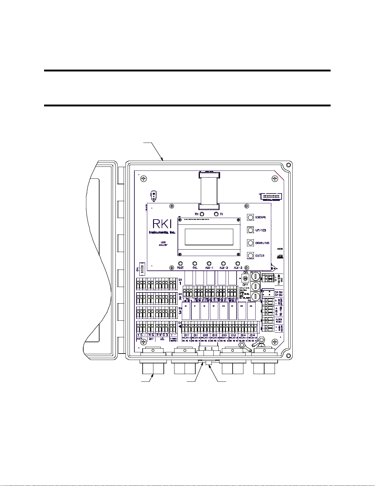
Chapter 2: Description
Housing
Reset S witchBuzzer3/4 " ConduitHub (4X)
Overview
This chapter describes the Beacon 410A’s external and internal components.
External Description
This section describes the housing and all external components of the Beacon 410A. For
the purposes of this description, the housing door is considered the front of the monitor.
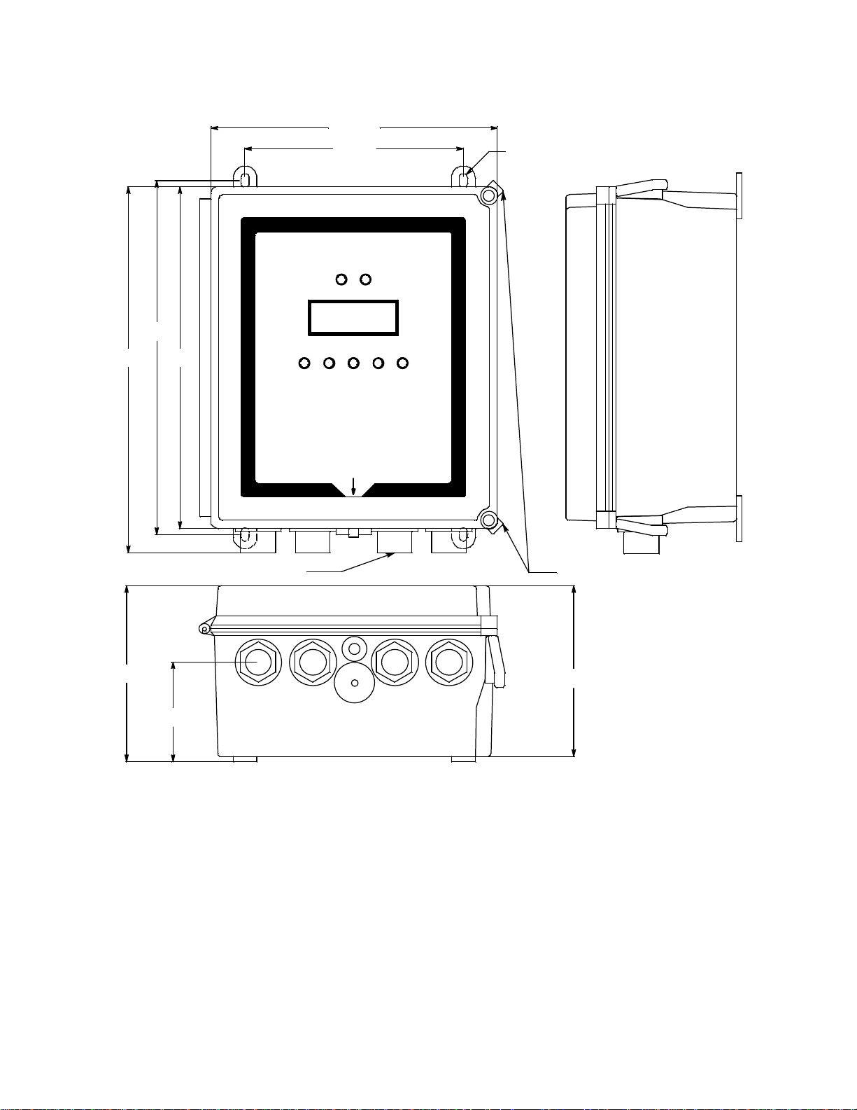
Figure 1: External Component Location
Housing
The Beacon 410A’s fiberglass housing is weather- and corrosion-resistant. It is suitable for
installation where general purpose equipment is in use. The housing door is hinged on the
left side and is secured by two latches on the right side. The OLED display and status
LEDs are visible through windows in the housing door. Four mounting feet are attached to
8 • Overview Beacon 410A Gas Monitor Operator’s Manual
Page 9

the back of the housing (one at each corner). The mounting feet allow you to install the
housing to a vertical surface. Four conduit hubs on the bottom of the housing are for
external wiring connections.
CAUTION: Only use the four factory installed conduit hubs on the bottom of the housing
for wire entry into the housing. Do not drill the housing for any reason.
CAUTION: To avoid electrical interference, do not route detector head and power wiring
through the same conduit hub.
Reset Switch
The reset switch is on the bottom of the housing in front of the buzzer. The reset switch
serves five functions:
• Resets the alarm circuits for “latched” alarms after an alarm 1, alarm 2, or alarm 3
condition passes.
You can set each channel for latched or self-resetting alarms in the Configuration
Menu. See “Viewing and Changing Channel Parameters” on page 46 for more
information.
• Silences the buzzer during an alarm 1, alarm 2, or alarm 3 condition if the buzzer
silence parameter in the Global Menu is set to CAN SILENCE BUZZER. See “Viewing
and Changing Global Parameters” on page 43 for more information on setting the
silence feature.
• Resets the strobe during an alarm 1, alarm 2, or alarm 3 condition if the strobe alarm
setting parameters are set to Resettable STROBE in the Configuration Menu. See
“Viewing and Changing Channel Parameters” on page 46 for more information on
setting the strobe alarm setting parameters.
• Displays and resets the minimum and maximum gas concentration values detected.
• Silences the buzzer during a fail condition.
NOTE: Fail alarms cannot be reset with the reset switch. When a fail condition passes,
the Beacon 410A will automatically reset the fail alarm circuit.
Buzzer
The buzzer is on the bottom of the housing, behind the reset switch. The buzzer sounds
an audible alarm to warn you of gas alarms and instrument failures.
Beacon 410A Gas Monitor Operator’s Manual External Description • 9
Page 10
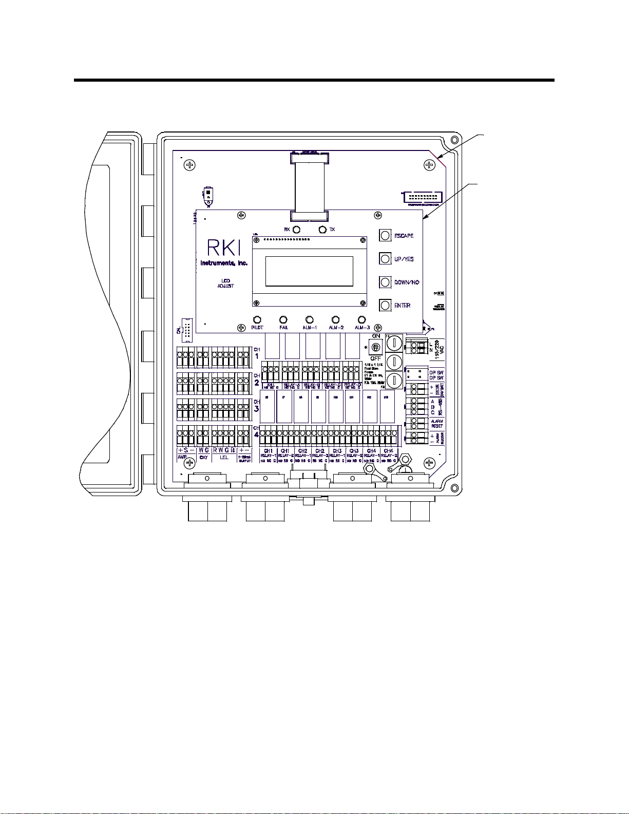
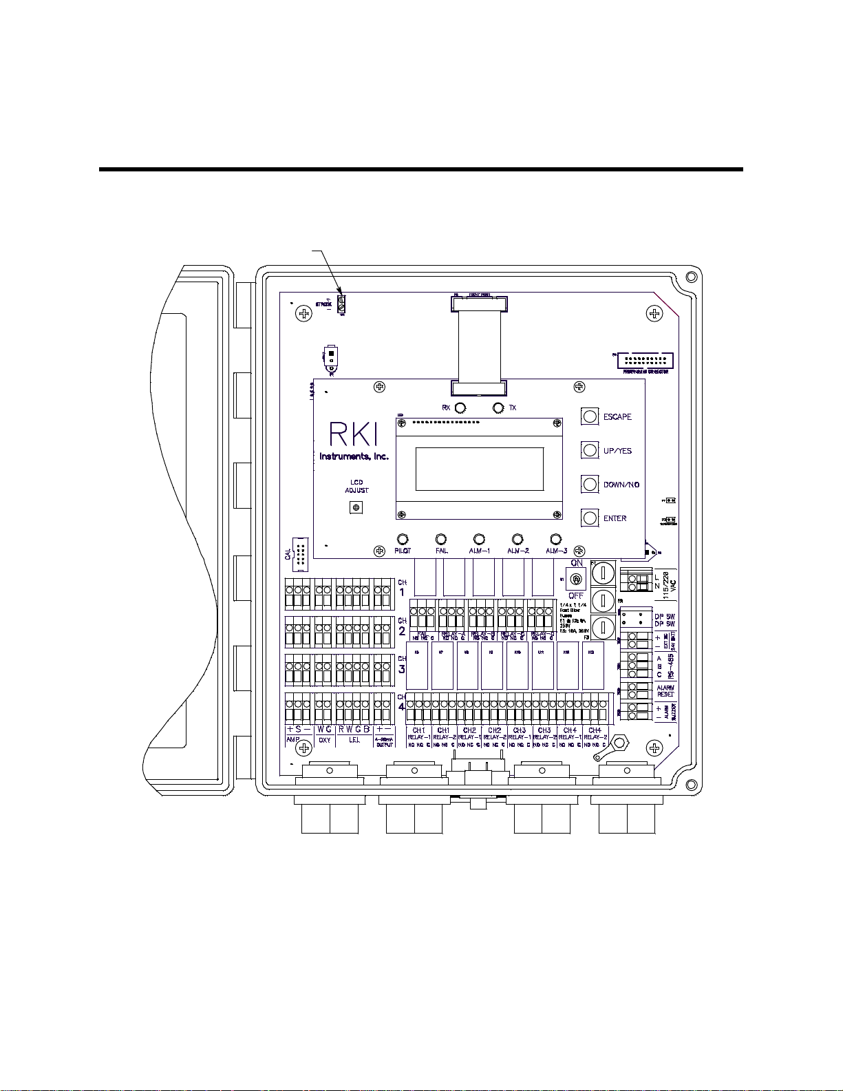
Internal Description
Control PCB
Main PCB
This section describes the internal components of the Beacon 410A.
Figure 2: Beacon 410A Gas Monitor Internal Component Location
Control PCB
The control PCB (printed circuit board) is mounted to the power supply mounting plate
which is in turn mounted to the main PCB. The power supply mounting plate and main
PCB are described below. The control PCB includes the OLED display, the status LEDs,
and the program buttons. It is connected to the main PCB by the display cable which is a
20 conductor ribbon cable assembly. The display cable connects to a rectangular
connector on the top edge of the control PCB and to the same type of connector labelled
“FRONT PANEL” on the top edge of the main PCB.
10 • Internal Description Beacon 410A Gas Monitor Operator’s Manual
Page 11
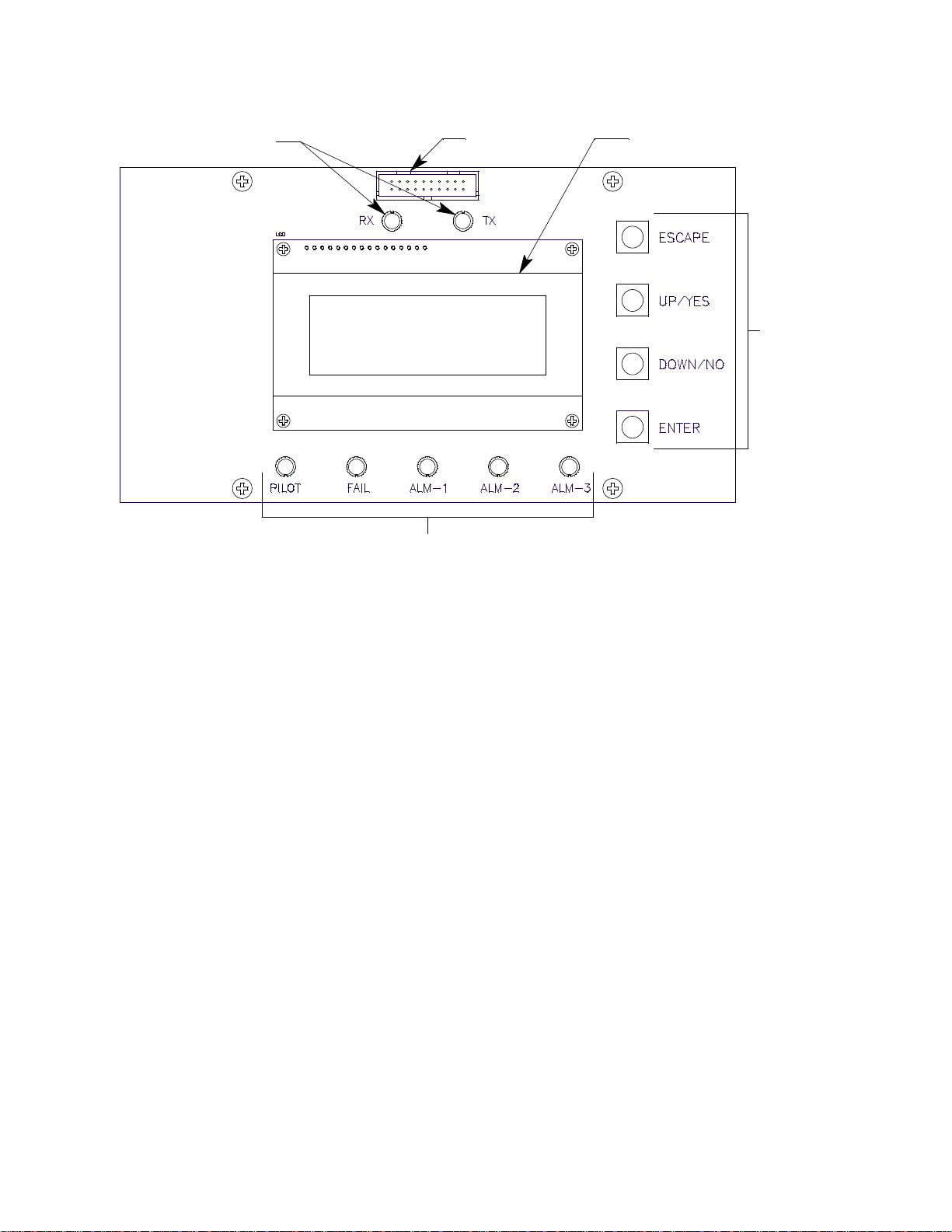
Status LEDs
OLED DisplayDisplay Cable
Connector
Status LEDs
Control
Switches
Figure 3: Control PCB Component Location
OLED Display
During normal operation, the four line display simultaneously indicates the target gas,
current gas reading, and measuring unit of each active channel. The display also shows
messages, settings, and other data when you are operating the various selection menus
and operating modes. The display appearance cannot be adjusted so no adjustment pot is
needed for the OLED display.
Status LEDs
The Beacon 410A includes seven status LEDs that indicate the current status of the
monitor: the RX & TX LEDs, the pilot LED, the fail LED, the alarm 1 LED, the alarm 2 LED,
and the alarm 3 LED (see Figure 3).
• RX & TX LEDs
These LEDs indicate data being received (RX) and transmitted (TX) when the Beacon
410A’s Modbus output is operating.
• Pilot LED
The PILOT LED is on when the Beacon 410A is receiving incoming power, either AC
or DC power.
• Fail LED
The fail LED turns on when the Beacon 410A is experiencing a fail condition. A fail
condition can be caused by a failure within the Beacon 410A or the detector heads
wired to the Beacon 410A (see “Chapter 10: Maintenance” on page 76).
• Alarm 1 LED
The alarm 1 LED is on when the Beacon 410A is experiencing an alarm 1 condition.
Beacon 410A Gas Monitor Operator’s Manual Internal Description • 11
Page 12

• ALARM 2 LED
The alarm 2 LED is on when the Beacon 410A is experiencing an alarm 2 condition.
• ALARM 3 LED
The alarm 3 LED is on when the Beacon 410A is experiencing an alarm 3 condition.
Control Buttons
The Beacon 410A includes four control buttons that allow you to enter the selection
menus and Calibration Mode, navigate through the menus and Calibration Mode, update
instrument and channel parameter settings, and save changes to the settings. The control
buttons, listed in Table 2, are to the right of the OLED display (see Figure 3).
Table 2: Beacon 410A Control Button Functions
Button Function
ESCAPE • Moves backward through the menu and mode screens
• Aborts operations
• Cancels changes you make in the menus
• Enters the Configuration Menu (press with ENTER button)
• Enters the Global Menu (press with the UP/YES button)
UP (YES) • Initiates an operation or proceeds to the next screen when a yes/
no question is asked on a screen
• Changes the displayed setting
• Enters the Global Menu (press with ESCAPE) button
• Enters the Calibration Mode (press with ENTER button)
DOWN (NO) • Cancels an operation or sequence when a yes/no question is
asked on a screen.
• Changes the displayed setting
• Enters the Modbus Menu (press with ENTER button)
ENTER • Saves changes you make in the menu and mode screens
• Accepts the displayed parameter setting
• Enters the Configuration Menu (press with ESCAPE button)
• Enters Calibration Mode (press with UP/YES button)
• Enters the Modbus Menu (press with DOWN/NO button)
12 • Internal Description Beacon 410A Gas Monitor Operator’s Manual
Page 13
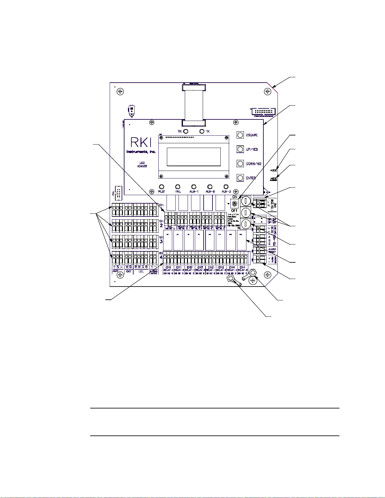
Main PCB
Termination
Jum per
Ground
Jumper
Power S witch
Main PCB
Control PCB
Controller
Terminal S trip
Relay (13X)
Field G round St ud
DC Fuse
AC Fuses
Common/
Channel Al arm
Termina l Strip
Channel A larm
Terminal S trip
Detector/
Transmitter
Terminal
Strips
Factory G round Stud
AC In
Terminal S trip
The main PCB contains: terminal strips, relays, a termination jumper, a ground jumper,
ground studs, the power switch, the power supply, and fuses.
Figure 4: Main PCB Component Location
Terminal Strips
The Beacon 410A includes 9 terminal strips for wiring connections. See “Wiring the
Beacon 410A Gas Monitor” on page 22 for detailed wiring procedures.
• Strobe Terminal Strip
The strobe terminal strip is a 2-point terminal strip located in the upper left corner of
the main PCB. When the optional strobe is ordered with a Beacon 410A, the strobe
terminal strip is used to factory wire the strobe.
CAUTION: The strobe terminals are intended for use with the RKI supplied optional
strobe. Consult RKI Instruments, Inc. before attempting to use these
terminals for some other alarm device.
Beacon 410A Gas Monitor Operator’s Manual Internal Description • 13
Page 14

• Detector/Transmitter Terminal Strips
Four detector/transmitter terminal strips are located along the bottom left side of the
main PCB (see Figure 4 on page 13). These four 11-point terminal strips facilitate
wiring connections to the detector heads. They also provide terminals to connect a
recording device to a 4 to 20 mA output for each channel. The top terminal strip is for
channel 1 connections and each subsequent strip is used for the next channel with the
bottom terminal strip being for channel 4 connections.
• Channel Alarm Terminal Strip
A channel alarm terminal strip is located to the right of the channel 4
detector/transmitter terminal strip (see Figure 4 on page 13). This 24-point terminal
strip facilitates wiring external alarm devices (horn, light, etc.) to relay contacts that
are field configurable for alarm levels and operation and are controlled by individual
channels.The contacts are labelled NO (normally open), NC (normally closed),
and C (common). See “Viewing and Changing Global Parameters” on page 43 and
“Viewing and Changing Channel Parameters” on page 46 for instructions to configure
the operation of these contacts.
• Common/Channel Alarm Terminal Strip
The common/channel alarm terminal strip is located in approximately the middle of the
main PCB above the channel alarm terminal strip. This 15-point terminal strip
facilitates wiring external alarm devices (horn, strobe, etc.) to relay contacts that are
field configurable as individual alarm contacts that are controlled by individual
channels or as common alarm contacts which are controlled by all channels. The
contacts are labelled NO (normally open), NC (normally closed), and C (common).
See “Viewing and Changing Global Parameters” on page 43 and “Viewing and
Changing Channel Parameters” on page 46 for instructions to configure the operation
of these contacts.
• Controller Terminal Strip
The 9-point controller terminal strip is along the lower right side of the main PCB (see
Figure 4 on page 13). The controller terminal strip facilitates various internal and
external wiring connections. Table 3 lists the function of each terminal.
Table 3: Terminal Assignments for the Controller Terminal Strip
Terminal Connects to:
EXT DC/24V BATT +
EXT DC/24V BATT -
+ connection from 24 VDC power source
- connection from 24 VDC power source
1
(or 24 V backup battery)
1
(or 24 V backup battery)
RS-485 A
RS-485 B Allow connection of the Beacon 410A to a Modbus network
RS-485 C
Alarm Reset
Alarm Reset
Reset Switch Terminals (factory wired)
Alarm Buzzer + Buzzer + connection (factory wired)
Alarm Buzzer - Buzzer - connection (factory wired)
1
If 24 VDC is used as primary power source do not make wiring connections to the AC terminal strip.
1
1
14 • Internal Description Beacon 410A Gas Monitor Operator’s Manual
Page 15
• AC Terminal Strip
Relay
B
CH 4
Relay
2
CH 3
Relay
1
Relay
A
DC Fuse
CH 1
Relay
1
CH 2
Relay
2
Channel
Relays
CH 4
Relay
1
Relay
C
Fail
Relay
CH 1
Relay
2
AC Fuses
Power Switch
CH 2
Relay
1
Common/Channel Relays
Relay
D
CH 3
Relay
2
The 2-point AC terminal strip is located above the controller terminal strip (see
Figure 4 on page 13). The AC terminal strip facilitates wiring connections to the AC
power source.
Table 4: Terminal Assignments for the AC Terminal Strip
Terminal Connects to:
LINE Hot wire from AC power source.
NEUT Neutral wire from AC power source.
NOTE: The AC power source’s ground wire must be connected to the field ground stud.
See “Connecting the AC Power Source” on page 24 for instructions.
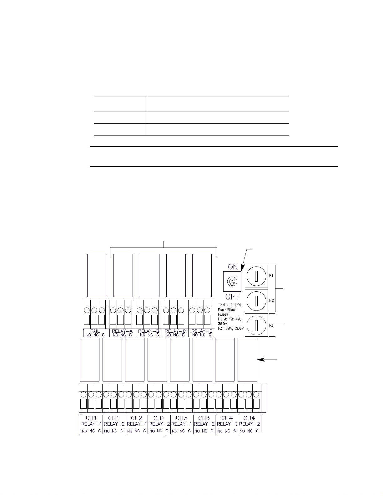
Relays
The Beacon 410A includes eight channel relays and one common fail relay. It also
includes four common/channel relays that can be defined as a group as channel or
common relays. All the relays have single-pole double-throw (SPDT) contacts, also known
as form C contacts, and are rated for 10 amps at 115 VAC (resistive). The contacts are
available at the channel alarm and common/channel alarm terminal strips and are labelled
NO (normally open), NC (normally closed), and C (common).
Figure 5: Beacon 410A Relay Allocation
Beacon 410A Gas Monitor Operator’s Manual Internal Description • 15
Page 16

• Channel Relays & Fail Relay
The eight channel relays are above the channel alarm terminal strip (see Figure 4 on
page 13 and Figure 5 on page 15). These relays are dedicated to specific channels.
Figure 3 illustrates the allocation of the channel relays.
The fail relay is located directly to the left of the channel relays. The fail relay is a
common relay.
• Common/Channel Relays
The four common/channel relays are above the common/channel alarm terminal strip
(see Figure 4 on page 13 and Figure 5 on page 15). These relays can be configured
as either all channel relays or all common relays in the Global Menu.
Termination Jumper
A two pin header with a termination jumper installed is located along the right edge of the
main PCB a short distance above the AC In terminal strip. It is labelled “P3” and “RS-485
Terminator” on the PCB silkscreen. Although this jumper has no function unless the
Beacon 410A is wired into a Modbus installation, leave it installed unless directed to
remove it for a a Modbus installation. See “Chapter 9: RS-485 Modbus Output” on
page 66 for instructions to use the Beacon 410A in a Modbus system.
Ground Jumper
A two pin header with a jumper installed is located along the right edge of the main PCB
just above the termination jumper. It is labelled “P3” on the PCB silkscreen. Leave this
jumper installed unless directed to remove it for a Modbus installation. See “Chapter 9:
RS-485 Modbus Output” on page 66 for instructions to use the Beacon 410A in a Modbus
system.
Ground Studs
Two ground studs are located in the bottom right corner of the main PCB. The left one is
unlabeled and is for factory grounding connections. The one on the right is labeled with a
ground symbol and is for the field ground connection. A kep nut on the field grounding
stud may be removed for installation of one or more user supplied lugs to make wiring
connections to earth ground. This stud is typically used to connect the shield drain wire of
shielded cable to earth ground at the Beacon 410A.
Power Switch
The power switch is between the common/channel relays and the fuses (see Figure 4 on
page 13 and Figure 5 on page 15). The power switch turns the incoming AC power source
on and off at the Beacon 410A. When the switch is up, the power is on.
Power Supply
The power supply is mounted to the power supply mounting plate which is located behind
the display PCB. The power supply mounting plate is mounted to the main PCB with four
standoffs. The power supply receives AC power from the external power source and
converts it to a DC voltage that is usable by the Beacon 410A circuitry. A polycarbonate
cover prevents accidental contact with the AC terminals on the power supply.
Fuses
Two AC fuses and one DC fuse are used in the Beacon 410A. The fuses are located on
the right side of main PCB, between the power switch and the AC in terminal strip (see
Figure 4 on page 13 and Figure 5 on page 15). The AC fuses are labelled F1, F2 and the
DC fuse is labelled F3 on the PCB silkscreen. They cut off the incoming AC or DC power
in the event of a short circuit or other electrical fault which causes a high current draw in
16 • Internal Description Beacon 410A Gas Monitor Operator’s Manual
Page 17
the Beacon 410A. They are housed in vertical fuse holders and are held in each holder by
Strobe Terminal Strip
a quarter turn cover. The AC fuses are rated at 6 A, 250 V, 1/4 x 1 1/4 inch, fast acting.
The DC fuse is rated at 10A, 250V, 1/4 x 1 1/4 inch, fast acting.
Optional Accessories
This section describes the optional accessories available for the Beacon 410A. Both
optional accessories are wired to the Strobe Terminal Strip as shown below.
Figure 6: Strobe Terminal Strip Location
Beacon 410A Gas Monitor Operator’s Manual Optional Accessories • 17
Page 18
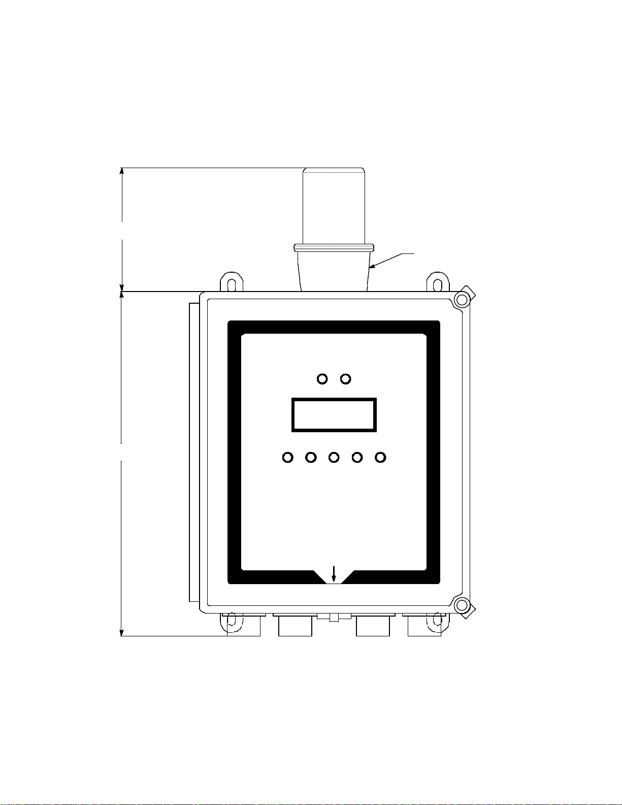
Alarm Strobe
Strobe (Optional)
13.39
4.92
The Beacon 410A can be ordered with an alarm strobe light installed on the top of the
housing. The Beacon 410A retains its NEMA 4X rating with the strobe installed. Strobe
operation can be programmed in Configuration Mode (see “Chapter 6: Configuration
Menu” on page 46). The outline and mounting dimensions with the alarm strobe are the
same as the standard Beacon 410A with the exception of the height. The difference is
shown below. See Figure 9 for all outline and mounting dimensions.
Figure 7: Alarm Strobe Dimensions
Horn/Strobe
The Beacon 410A can be ordered with a horn/strobe. This optional horn/strobe allows the
user to have both a strobe and a horn connected to the “Strobe” terminals of the Beacon
410A. If the horn/strobe is not factory installed, it also allows the user to mount the horn/
strobe away from the Beacon 410A so that it can be somewhere more visible/audible.
18 • Optional Accessories Beacon 410A Gas Monitor Operator’s Manual
Page 19
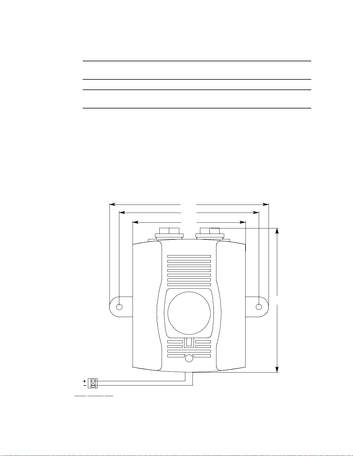
Strobe operation can be programmed in Configuration Mode (see “Chapter 6:
Strobe Terminal Strip
-
Dimensions Shown in Inches
4.83
6.81
5.97
6.17
+
Configuration Menu” on page 46).
NOTE: See “Chapter 3: Installation and Start Up” on page 20 for complete Beacon 410A
installation instructions.
CAUTION: Do not adjust the strobe b rightness or the horn volume at the strobe/horn, as this
may overload the Beacon 410A strobe control circuit.
The optional horn/strobe is generally not factory installed and needs to be installed by the
user. The following instructions describe the installation of the horn/strobe. If the horn/
strobe is factory installed, the following instructions do not apply.
1. Mount the horn/strobe in the desired location.
2. Install an appropriately rated cable bushing or conduit to the left conduit hub on the
bottom of the Beacon 410A housing.
3. Install an appropriately rated cable bushing or conduit at the horn/strobe.
4. Run a cable or wires in conduit from the horn/strobe to the Beacon 410A through the
left conduit hub.
5. Connect the wires to the strobe terminal strip as shown in the figure below.
Figure 8: Horn/Strobe Wiring/Outline and Mounting Dimensions
Beacon 410A Gas Monitor Operator’s Manual Optional Accessories • 19
Page 20

Chapter 3: Installation and Start Up
Overview
This chapter describes procedures to mount the Beacon 410A Gas Monitor, make wiring
connections to the monitor, and start up the monitor.
WARNING: Perform all installation and start-up procedures in a kn ow n fresh air
environment, an environment free of combustible and toxic gasses and of nor mal
oxygen content. The Beacon 410A is not in operation as a gas monitoring
controller until the start up procedure is complete.
Mounting the Beacon 410A Gas Monitor
WARNING: Only authorized and properly trained personnel should perform any mounting
procedures.
Perform the following procedure to install the Beacon 410A at the mounting site.
1. Select the mounting site. When you select the mounting site, consider the following
factors:
• Is an AC or DC power source available?
• Is a vertical surface available to mount the Beacon 410A?
• Is there enough room to open the housing door and make wiring connections
through the conduit hubs at the bottom of the housing?
• Are the display screen and status lights visible?
2. Close and latch the housing door.
3. The Beacon 410A is shipped with the mounting feet positioned under the housing.
Loosen the screws that secure the feet to the housing, rotate the feet to their mounting
position as shown in Figure 9, then tighten the screws.
4. Prepare the selected mounting site as required to mount the Beacon 410A. It should
be mounted at eye level (4 1/2 to 5 feet from the floor). Refer to Figure 9 for the outline
and mounting dimensions.
5. Position the monitor on the vertical mounting surface.
6. Insert 1/4 in. screws through the slots in the mounting feet at each corner of the
housing to secure the housing to the mounting surface.
7. Each of the door clamps has a feature for locking device installation. A locking device
that requires a tool to unlock must be installed in each door clamp.
20 • Overview Beacon 410A Gas Monitor Operator’s Manual
Page 21
Ø .31 x .50 slot, 4X
Door Latches
13.39
12.94
12.50
3/4" Conduit Hubs, 4X
6.43
3.63
8.00
6.25
10.50
Figure 9: Beacon 410A Gas Monitor Outline and Mounting Dimensions
Beacon 410A Gas Monitor Operator’s Manual Mounting the Beacon 410A Gas Monitor • 21
Page 22

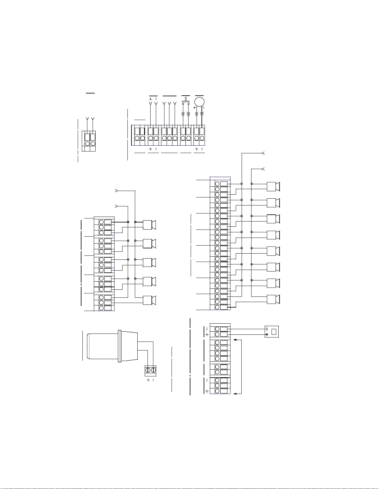
Wiring the Beacon 410A Gas Monitor
This section describes procedures to connect the AC power source, DC power source,
Modbus wiring (refer to “Wiring the Beacon 410A in a Modbus System” on page 66),
external alarms, recording devices, and detector heads. See Figure 10 on page 23 for a
general diagram of all external wiring to the Beacon 410A.
W ARNIN G: Make all connections to the Beacon 410A before you plug in or turn on t he AC or
DC power source. Before you make any wiring adjustments, always verify that all
power sources are not live.
Routing Wiring Into the Beacon 410A Housing
Wiring must be brought into the housing through one of the four factory-installed conduit
hubs on the bottom of the housing.
Do not
drill into the Beacon 410A housing for any reason. Drilling the Beacon 410A
housing and routing wiring through holes not factory drilled will void the warranty
could result in:
• Damage to internal components from the drilling process.
and
• Moisture damage to internal components from poorly sealed holes.
• Unpredictable Beacon 410A behavior due to EMI/RFI interference caused by wires
routed across the PCBs.
• Possible shorting of Beacon 410A components due to wires routed across the PCBs.
22 • Wiring the Beacon 410A Gas Monitor Beacon 410A Gas Monitor Operator’s Manual
Page 23
Neutral
Not
Used
L
N
AC
RS - 485
BAC
EXT DC
24V BATT
DP SW
ALARM
BUZZER
Alarm Device
Power
CH 4
RELAY-1
NO N C C
NO NC C
RELAY-CRELAY-AFAIL
NO NC C NO NC C
CH 3
RELAY-1
NO NC CNO NC C
CH 2
RELAY-2
CH 1
RELAY-2
NO NC C NO NC C
CH 1
RELAY-1
LEL
WG
4-20 m A
OUTPUT
B
OXY
S
AMP
GW
CH 4
RELAY-2
NO NC C
Buzzer
(Factory wired)
Alarm Dev ic e
Power
24V DC
See Modbus Wiring
In Chapter 9
Li ne (Hot)
AC Power
100/ 115 VAC
50 / 60 Hz
RELAY-B
NO N C C
NO NC C
CH 2
RELAY-1
Black
Red
Strobe Terminal Strip
(Factory wired)
Option al St robe
R
Refer to Detector Head Manual
And Beacon 410A D etector Head
Specification Sheet for Specific
Detector/Transmi tter Wiring
NOTE: Line and Neutral are L1 and L2 for 220 V AC wiring.
NOTE: AC ground connection is made to field
ground stud in lower right corner of circuit board.
AC
InTerminalStrip
Controller Termi nal Strip
Reset Switch
(Factory wired)
ALARM
RESET
Recording Device
500 Oh ms Impedan ce M ax i mum
Detector / Transmitter Terminal Strip
(typical 1 of 4)
NO NC C
CH 3
RELAY-2
Channel Alarm Terminal St rip
Alarm Dev ices, Typical Alarm Wiring Shown
Relay Contacts Rated For 10 Amps At 250 VAC
Alarm Devices, Typical Alarm Wiring Shown
Relay Contacts Rated For 10 Amps At 250 VAC
Common / Channel Alarm Terminal Strip
NO NC C
RELAY-D
Beacon 410A Gas Monitor Operator’s Manual Wiring the Beacon 410A Gas Monitor • 23
Figure 10: Beacon 410A Gas Monitor External Wiring Diagram
Page 24

Connecting the AC Power Source
NOTE: If you are using DC power as the primary power source, go to the next section,
“Connecting the DC Power Source”.
The AC in terminal strip will accept 24 - 14 AWG wire. For 115 VAC connection, select wire
that is sized appropriately for the power requirements of the connected device and that is
rated to a minimum of 80°C and 150 V. For 220 VAC connection, select wire that is sized
appropriately for the power requirements of the connected device and that is rated to a
minimum of 80°C and 250 V. When selecting wire, be sure to meet the local electrical
code.
A certified switch of circuit breaker must also be installed in the AC line. For 115 VAC
connection, the switch or circuit breaker must be rated to 115 VAC, 50/60 Hz, and 0.5 A.
For 220 VAC connection, the switch or circuit breaker must be rated to 220 VAC,
50/60 Hz, and 0.3 A.
Perform the following procedure to connect the AC power source to the Beacon 410A.
WARNING: Verify that the power source is unplugged or turned off before you continue with
this procedure.
1. Turn off or disconnect mains power to the Beacon 410A.
2. Open the housing door, then place the power switch in the OFF position.
CAUTION: The power switch does not control DC input power.
3. Locate the AC in terminal strip (see Figure 2 on page 10). The terminals are labelled L
and N for line and neutral respectively.
4. Install an appropriately rated cable bushing or conduit in the right-most conduit hub on
the bottom of the Beacon 410A housing.
CAUTION: Only use the four factory installed conduit hubs on the bottom of the housing
for wire entry into the housing. Do not drill the housing for any reason. See
“Routing Wiring Into the Beacon 410A Housing” on page 22 for more
information.
5. Guide the AC power cord or wires in conduit through the right-most conduit hub on the
bottom of the Beacon 410A housing.
CAUTION: Do not route power and detector head wiring through the same conduit hub.
The power wiring may disrupt the transmission of the detector head signal to
the monitor.
24 • Wiring the Beacon 410A Gas Monitor Beacon 410A Gas Monitor Operator’s Manual
Page 25

6. Connect the AC wires to the AC in terminal strip as shown in Figure 11 below.
L1
AC Power
220 VAC
50 / 60 Hz
AC Power
100/115 VAC
50 / 60 Hz
100/115 VAC Wiring
Disconnect
Device
Line (Hot)
Neutral
Disconnect
Device
L2N
L
L
N
AC In
Terminal Strip
AC In
Terminal Strip
220 VAC Wiring
Beacon 410A Gas Monitor Operator’s Manual Wiring the Beacon 410A Gas Monitor • 25
Figure 11: AC Power Wiring
7. Connect the ground wire to the crimp terminal that is factory installed on the field
ground stud. The field ground stud is located n the lower right corner of the main PCB
and is marked with a ground symbol. See Figure 2 on page 10. A factory ground stud
is located just to the left of the field ground stud and is not for field use.
a. Remove the lug from the field ground stud. There is only 1 lug on the stud.
b. Crimp the ground wire to the lug.
c. Reinstall the lug.
WARNING: Follow this grounding procedure to maintain the CSA classification of the
Connecting the DC Power Source
WARNING: Verify that the power source is unplugged or turned off before you continue with
Beacon 410A.
this procedure.
DC power may be used as a primary power source. If DC power (connected to the 24
VDC terminals) is the primary power source, DO NOT connect AC power to the AC In
terminal strip.
A 24 VDC battery (connected to the 24 VDC terminals) may also be used as a backup
power source if AC power (connected to the AC In terminal strip) is the primary power
source. If your Beacon 410A does not include the battery charging feature, you may use a
self contained 24 VDC backup that keeps its batteries charged while AC power is on and
recharges the batteries when AC power returns after a power failure. If your Beacon 410A
Page 26

includes the battery charging feature, see “Battery Charging (Optional)” on page 36 for a
DC Pow er In Terminals on
Contr o ller Terminal Strip
EXT DC
24V BATT
DC Power
24 VDC
complete description of this feature and what type of battery to use.
The controller terminal strip will accept 24 - 14 AWG wire. Select wire that is sized
appropriately for the power requirements of the connected device and that is rated to a
minimum of 80°C and 150 V. When selecting wire, be sure to meet the local electrical
code.
WARNING: The 24 VDC terminals are only intended for connecting a battery or a 24 VDC
supply to the Beacon 410A. Do not connect any horns or strobes to the 24 VDC
terminals.
1. Turn off or disconnect mains power to the Beacon 410A.
2. Open the housing door, then place the power switch in the OFF position.
CAUTION: The power switch does not control DC input power.
3. Locate the DC input power terminals on the controller terminal strip near the lower
right edge of the main PCB (see Figure 2 on page 10). They are labelled EXT DC/24V
BATT+ and EXT DC/24V BATT -.
4. Install an appropriately rated cable bushing or conduit in an unused conduit hub on
the bottom of the Beacon 410A housing.
CAUTION: Only use the four factory installed conduit hubs on the bottom of the housing
for wire entry into the housing. Do not drill the housing for any reason. See
“Routing Wiring Into the Beacon 410A Housing” on page 22 for more
information.
5. Guide a DC power cord or two wires in conduit through the selected conduit hub on
the bottom of the Beacon 410A housing.
CAUTION: Do not route power and detector head wiring through the same conduit hub.
The power wiring may disrupt the transmission of the detector head signal to
the monitor.
6. Connect the DC power wires to the controller terminal strip as shown in Figure 12
below.
Figure 12: DC Power Wiring
26 • Wiring the Beacon 410A Gas Monitor Beacon 410A Gas Monitor Operator’s Manual
Page 27

NOTE: The Beacon 410A will operate from the DC input down to 18.5 volts. If a self
contained backup battery is used, see its operator’s manual for a description of
its recharging characteristics. If your Beacon 410A includes the battery charging
feature and a backup battery is used, the Beacon 410A will recharge the battery
when AC power has returned after a power failure. See “Battery Charging
(Optional)” on page 36 for a complete description of the battery charging feature.
RS-485 Modbus Wiring
See “Wiring the Beacon 410A in a Modbus System” on page 66 for wiring connections to
the RS-485 Modbus terminals.
Connecting External Alarms
Before connecting any external alarm devices to the relay contacts, make sure you know
how you want the devices to operate. For example, confirm under what alarm condition
you want a device to turn on or turn off and what channel is going to control the device.
Also make sure that the parameter settings that apply to the relays in the Global Menu and
the Configuration Menu are set so that the desired alarm device operation is obtained.
See “Viewing and Changing Global Parameters” on page 43 and “Viewing and Changing
Channel Parameters” on page 46 for information about the relay parameters.
The alarm terminals will accept 24 - 14 AWG wire. Select wire that is sized appropriately
for the power requirements of the connected device and that is rated to a minimum of
80°C and up to 250 V depending on the device being powered.
WARNING: Do not connect external alarms to the 24 VDC terminals.
Perform the following procedure to connect external alarm devices to the Beacon 410A.
1. Turn off or disconnect mains power to the Beacon 410A.
2. Open the housing door, then place the power switch in the OFF position.
CAUTION: The power switch does not control DC input power.
3. Locate the applicable alarm terminal strip (see Figure 2 on page 10).
4. Install an appropriately rated cable bushing or conduit in an unused conduit hub on
the bottom of the Beacon 410A.
CAUTION: Only use the four factory installed conduit hubs on the bottom of the housing
for wire entry into the housing. Do not drill the housing for any reason. See
“Routing Wiring Into the Beacon 410A Housing” on page 22 for more
information.
5. Guide the wiring of the external alarm device through the selected conduit hub on the
bottom of the Beacon 410A housing.
CAUTION: Do not route the external alarm wiring and detector head wiring through the
same conduit hub. The external alarm wiring may disrupt the transmission of
the detector head signal to the Beacon 410A.
Beacon 410A Gas Monitor Operator’s Manual Wiring the Beacon 410A Gas Monitor • 27
Page 28

6. Connect the leads from the external alarm device and an external power source to the
External
Power Source
(+) H
(-) N
Channel1, Relay1 A larm Terminals
From Channel Alarm Terminal Strip
NO NC C
CH 1 RELAY 1
External Alarm Device
selected channel alarm or common/channel alarm relay contact terminals as shown in
Figure 8.
Figure 13: External Alarm Wiring
7. Repeat step 5 and step 6 for additional external alarm devices.
Connecting Recorders
Perform the following procedure to connect an analog signal recording device to the
Beacon 410A. The output at the recorder output terminals for each channel is a 4 - 20 mA
signal that corresponds to the detection range of the detector head connected to that
Beacon 410A channel. Be sure to read the recording device’s operator’s manual before
installation and follow all wiring procedures and recommendations made by the recording
device’s manufacturer.
The recorder output terminals will accept 24 - 14 AWG wire. Select wire that is sized
appropriately for the power requirements of the connected device and that is rated to a
minimum of 80°C and 150 V.
1. Turn off or disconnect mains power to the Beacon 410A.
2. Open the housing door, then place the power switch in the OFF position.
CAUTION: The power switch does not control DC input power.
3. Locate the recorder output terminals on the right end of the detector/transmitter
terminal strips. See “Beacon 410A Gas Monitor Internal Component Location” on
page 10 to assist you in locating the recorder output terminals. They are labelled 4 -
20 mA OUTPUT + and 4 - 20 mA OUTPUT -.
4. Install an appropriately rated cable bushing or conduit in an unused conduit hub on
the bottom of the Beacon 410A housing.
CAUTION: Only use the four factory installed conduit hubs on the bottom of the housing
for wire entry into the housing. Do not drill the housing for any reason. See
“Routing Wiring Into the Beacon 410A Housing” on page 22 for more
information.
28 • Wiring the Beacon 410A Gas Monitor Beacon 410A Gas Monitor Operator’s Manual
5. Guide the wiring from the recording device through the selected conduit hub on the
bottom of the Beacon 410A housing.
Page 29

6. Connect the leads from the recording device to the recorder output terminals of the
Recorder O utput Terminals From a
Detector/Transmitter Terminal Str ip,
Typical of 4
4-20 mA
OUTPUT
4 - 20 mA Input
Recording Device
500 Ohms Impedance
Maximum
selected active channels as shown in Figure 14 below.
Figure 14: Recorder Output Wiring
Connecting RKI Detector Heads
When a Beacon 410A is ordered from the factory, any detector heads that were ordered
with it are already setup on particular channels of the Beacon 410A. If you are adding an
RKI detector head to your existing system, you will need to setup one of the unused
channels to operate the detector head. See “Selecting the Detector Head Input Type and
Gas Setup” on page 53 for instructions to setup a new channel.
The detector/transmitter terminals will accept 24 - 14 AWG wire. Select wire that is sized
appropriately for the power requirements of the connected device and that is rated to a
minimum of 80°C and 150 V.
Perform the following procedure to connect an RKI detector head to the Beacon 410A.
1. Turn off or disconnect mains power to the Beacon 410A.
2. Open the Beacon 410A door and place the power switch in the off position.
CAUTION: The power switch does not control DC input power.
3. See the detector head operator’s manual for instructions on how to connect the
detector head to a controller.
4. Install an appropriately rated cable bushing or conduit in an unused conduit hub on
the bottom of the Beacon 410A housing.
CAUTION: Only use the four factory installed conduit hubs on the bottom of the housing
for wire entry into the housing. Do not drill the housing for any reason. See
“Routing Wiring Into the Beacon 410A Housing” on page 22 for more
5. Route the wires in conduit or shielded cable from the detector head through the
selected conduit hub into the Beacon 410A. See Table 5 below for wire size and
distance guidelines.
information.
6. Unshielded twisted pair cable in conduit or shielded twisted pair cable is
recommended for all the direct connect detector heads. For the LEL detector, pair and
Beacon 410A Gas Monitor Operator’s Manual Wiring the Beacon 410A Gas Monitor • 29
Page 30

twist the R & B wires and the W & G wires. Shielded cable or wires in conduit are
recommended for the 2-wire and 3-wire 4 - 20 mA transmitters.
7. Connect the wires from the detector head to the appropriate detector/transmitter
terminals on the appropriate channel. See the detector head operator’s manual and
the Beacon 410A Detector Head Specification Sheet for detector head connections to
the Beacon 410A. If shielded cable is used, leave the cable shield’s drain wire
disconnected and insulated at the detector head and connect the cable shield’s drain
wire at the Beacon 410A to the ground stud on the main PCB.
CAUTION: Do not route power and detector head wiring through the same conduit hub.
The power wiring may disrupt the transmission of the detector head’s signal
to the Beacon 410A.
Table 5: Wire Size Guidelines for RKI Detector Head Wiring
Number of
Detector Head Type
Direct Connect LEL 4 500 ft. 1,000 ft. 2,000 ft.
Direct Connect Oxygen 2 500 ft. 1,000 ft. 2,000 ft.
Direct Connect H2S 2 500 ft. 1,000 ft. 2,000 ft.
Direct Connect CO 2 500 ft. 1,000 ft. 2,000 ft.
Direct Connect ESM-01
type
2-Wire 4 - 20 mA
Transmitter
3-Wire 4 - 20 mA
Transmitter
Wires to
Controller
2 500 ft. 1,000 ft. 2,000 ft.
2 2,500 ft. 5,000 ft. 8,000 ft.
3 2,500 ft. 5,000 ft. 8,000 ft.
Max Distance
to Controller
w/18 Gauge
Wire
Max Distance
to Controller
w/16 Gauge
Wire
Max Distance
to Controller
w/14 Gauge
Wire
Connecting User-Supplied 4 - 20 mA Transmitters
The Beacon 410A may be used with a user supplied 2-wire or 3-wire 4 - 20 mA transmitter
which runs on 24 VDC. When this is done, the Beacon 410A is normally setup at RKI
Instruments with the following channel parameters: unit of measure, item name, and full
scale. For example, “PSI AIR” with a full scale of 10 PSI.
If a user supplied 4 - 20 mA transmitter is added in the field, it will be necessary to setup
the additional channel. See “Selecting the Detector Head Input Type and Gas Setup” on
page 53 for instructions to setup a new channel.
The detector/transmitter terminals will accept 24 - 14 AWG wire. Select wire that is sized
appropriately for the power requirements of the connected device and that is rated to a
minimum of 80°C and 150 V.
Perform the following procedure to connect a 4 - 20 mA transmitter which you supply to
the Beacon 410A.
30 • Wiring the Beacon 410A Gas Monitor Beacon 410A Gas Monitor Operator’s Manual
Page 31

1. Turn off or disconnect mains power to the Beacon 410A.
2-Wire Connection3-Wire Connection
4 - 20 mA Transmitter Term i nals
From Detector/Transmitter
Terminal Strip, Typical of 4
4 - 20 mA Transmitter Term inals
From Detector/Transmitter
Terminal Stri p, Typical of 4
S
AMP
4 - 20 mA
+ 24 VDC
2-Wire 4 - 20
mA Transm itter
3-Wire 4 - 20
mA Transm itter
- (DC G round)
4 - 20 mA
+ 24 VDC
S
AMP
Figure 15: Generic 4 to 20 mA Transmitter Wiring
2. Open the Beacon 410A door and turn off the power switch.
CAUTION: The power switch does not control DC input power.
3. See the transmitter’s operator’s manual for instructions on how to connect wires to the
transmitter.
4. Install an appropriately rated cable bushing or conduit in an unused conduit hub on
the bottom of the Beacon 410A housing.
CAUTION: Only use the four factory installed conduit hubs on the bottom of the housing
for wire entry into the housing. Do not drill the housing for any reason. See
“Routing Wiring Into the Beacon 410A Housing” on page 22 for more
information.
5. Route the wires from the transmitter through the selected conduit hub into the Beacon
410A.
6. Connect the wires from the transmitter to the appropriate channel’s
detector/transmitter terminal strip. See the transmitter operator’s manual for controller
terminal connections and wiring recommendations.
CAUTION: Do not route power and transmitter wiring through the same conduit hub. The
power wiring may disrupt the transmission of the transmitter’s signal to the
Beacon 410A.
Figure 15 below illustrates typical transmitter wiring connections.
Beacon 410A Gas Monitor Operator’s Manual Wiring the Beacon 410A Gas Monitor • 31
Page 32

Starting Up the Beacon 410A Gas Monitor
10
stnemurtsnIIKR
Beacon 4
0100
NF
0000:
in: 0001
10001000100
:
O
M
W
1000B
0
aM
H
VERSION I
Perform the following procedure to place the Beacon 410A into normal operation.
1. Complete the mounting and wiring procedures described earlier in this chapter.
2. Complete all installation procedures described in the detector head or user supplied
4 - 20 mA transmitter operator’s manuals.
3. Verify that all wiring connections are correct and secure and that the Beacon 410A’s
power switch is in the OFF position.
4. Plug in or turn on the incoming power source (AC or DC).
5. Turn on the power switch if AC power is used as primary power.
6. The following screen appears for a few seconds.
7. The Version Screen then appears. It shows the instrument’s hardware and firmware
versions for a few seconds. HW is the hardware version. Main is the main firmware
version. MB is the Modbus firmware version. The version numbers on the bottom line
are the firmware versions loaded for each channel.
To keep the version information screen on the display longer than a few seconds,
press and hold the ENTER button while it is being displayed. When you release the
ENTER button, the startup sequence will continue.
8. After the Version Screen has been displayed for a few seconds, WARMING UP
appears for each active channel. The warm-up time is counted down in seconds from
60 seconds for each active channel on the far right.
NOTE: To prevent unwanted alarms during warm up, the alarm circuits are not active
while the WARMING UP message is displayed.
9. Any unused channels are configured as NOT USED in the Configuration Menu at the
factory. For any unused channels, NOT USED is displayed on the line for that
channel.
If any channels have been configured as STANDBY in the Configuration Menu,
STANDBY is displayed on the line for that channel.
See “Viewing and Changing Channel Parameters” on page 46 for a description of the
NOT USED and STANDBY configurations.
32 • Starting Up the Beacon 410A Gas Monitor Beacon 410A Gas Monitor Operator’s Manual
Page 33

10. When the warm-up period is complete, normal operation will begin. During normal
:
OL
LEL%0ENAHTEM
1
2
3
4
:
:
:
CO 0 ppm
mpp0S2H
OXYGEN 20 . 9 %V
operation, the display will indicate the current gas reading and target gas. Verify that
the display is indicating the current gas reading and target gas for all active channels
after the warm-up period is complete and normal operation begins, for example:
11. Verify that the PILOT light is on. If the PILOT light is not on, see the troubleshooting
guide in “Troubleshooting” on page 76.
12. Perform the start-up procedure for each detector head or user supplied 4 - 20 mA
transmitter as described in the detector head or user supplied transmitter’s operator’s
manual.
Beacon 410A Gas Monitor Operator’s Manual Starting Up the Beacon 410A Gas Monitor • 33
Page 34

Chapter 4: Operation
:
OL
LEL%0ENAHTEM
1
2
3
4
:
:
:
CO 0 ppm
mpp0S2H
OXYGEN 20 . 9 %V
Overview
This chapter describes the Beacon 410A Gas Monitor in normal operation. This chapter
also describes the Beacon 410A in alarm 1, alarm 2, alarm 3, and fail conditions, and
suggests responses to these conditions.
Normal Operation
Normal operation is defined as follows:
• the start-up procedure is complete.
• the Beacon 410A is not indicating an alarm 1, alarm 2, alarm 3, or fail condition.
• the Beacon 410A is not running in one of the selection menus or Calibration Mode.
During normal operation, the Beacon 410A simultaneously displays the target gas, unit of
measure, and current gas reading for all active channels. The example below illustrates a
typical Beacon 410A channel allocation.
The PILOT LED is on indicating that the Beacon 410A is receiving incoming power.
4 - 20 mA Signal Output Operation
The output at the recorder output terminals on the detector/transmitter terminal strip for
each channel is a 4 - 20 mA signal that corresponds to the detection range of the Beacon
410A. During normal operation, this signal tracks the gas concentration on the display.
There are several circumstances where the signal output will not track the display reading
but will behave as follows:
• When the Beacon 410A is in its warm-up period, the signal output will be fixed at 4 mA
(zero) for all channel types except oxygen. For oxygen channels, the output will be
fixed at 17.4 mA (20.9% oxygen) while the Beacon 410A is in warm-up.
• When a channel’s input type is changed to a new direct connect type of detector head
in the Input Setup Menu, the display will indicate NEEDS AIR/GAS Cal for that
channel when you exit the Input Setup Menu and enter normal operation and will
continue to indicate this until Calibration Mode is entered and a calibration is
performed. If a custom gas name and range was defined in the Input Setup Menu, the
Beacon 410A will enter the Configuration Menu for you to verify the parameter
settings before continuing to the normal operation and displaying the NEEDS AIR/
GAS Cal message. In this situation, the signal output for the newly configured channel
will be fixed at 0.7 mA until a complete calibration is performed on that channel.
34 • Overview Beacon 410A Gas Monitor Operator’s Manual
Page 35

• If you enter the Global Menu, the Configuration Menu, the Input Setup Menu, the
:0 0
00
20.9 20.9
00
1
2
3
4
:
:
:
lamr
Mt n/Max Valuesei
o
s
Wai t To Ret urn To
noitarepOo
r
e
u
N
O
R
P
sh Reset Again T
Modbus Menu, or Calibration Mode, the signal output will be fixed at 3.5 mA until the
Beacon 410A returns to normal operation.
• If the Beacon 410A’s input power decreases below 18.5 volts so that the Beacon 410A
is in a low power alarm, the signal output is fixed at 0.7 mA until the low power alarm
is cleared.
• If the Beacon 410A goes into a fail condition, after a 30 second delay, the signal
output is fixed at 0.7 mA until the fail alarm is cleared. During the 30 second delay, the
output follows the detector output. In the case of a downscale reading, the displayed
gas reading will only go as low as -10% of full scale but the signal output will continue
to track the reading even if it’s lower than -10% of full scale.
• If a channel is setup as NOT USED, the signal output will be fixed at about 0.7 mA.
• If a channel is setup as STANDBY, the signal output will be fixed at 3.5 mA.
Viewing and Resetting Min/Max Readings
The Reset switch may be used to view and reset the minimum and maximum gas
readings for all active channels.
1. While the Beacon 410A is in normal operation, press and hold the reset switch button
for 5 seconds.
2. The display will show the following screen for about ten seconds.
The minimum reading is on the left and the maximum is on the right for each channel.
3. After the minimum and maximum readings have been displayed for about ten
seconds, the following screen appears for about seven seconds.
• To reset the minimum and maximum readings, before the unit returns to normal
operation press and release the reset switch button. The display indicates Min/
Max Values Have Been Reset and the unit will then return to normal operation.
• To return to normal operation without resetting the minimum and maximum read-
ings, do not press the reset switch button and allow the unit to return to normal
operation.
Beacon 410A Gas Monitor Operator’s Manual Viewing and Resetting Min/Max Readings • 35
Page 36

Battery Charging (Optional)
The Beacon 410A has an optional backup battery charging feature. In order for this
feature to be included, the Beacon 410A must be ordered with this feature. Consult RKI
Instruments, Inc. for ordering information.
The battery charging circuit is designed to charge lead acid type batteries. If AC power is
used as primary power and a backup battery is connected to the Beacon 410A ‘s EXT DC/
24V BATT terminals as shown in Figure 12 on page 26, the battery charging feature will
charge the battery if it is depleted and keep it charged with a charge current of
approximately 100 mA.
CAUTION: When a battery is used as backup power and the charging feature is included in the
Beacon 410A, do not use a non-rechargeable battery or a backup battery that has it’s
own charging feature. Use RKI backup battery 49-8104R K or an appropriately rate d
24 VDC rechargeable lead acid type battery to backup a Beacon 410A when the
battery charging feature is included in the Beacon 410 A.
Alarm Indications
This section describes the Beacon 410A in alarm 1, alarm 2, alarm 3 and fail conditions,
and suggests responses to these conditions. Table 6 below lists the alarm indications for
each condition.
NOTE: The Beacon 410A allows configuration of various alarm and alarm relay
parameters. The description of alarm indications below assumes that all
parameters are at their factory set value. It also assumes that the alarm setpoints
are set such that alarm 1< alarm 2 < alarm 3 and all alarms are increasing except
for an oxygen channel where alarm 1>alarm 3 and alarm 2 > alarm 3 because
alarm 1 and alarm 3 are decreasing alarms and alarm 2 is an increasing alarm.
See “Viewing and Changing Channel Parameters” on page 46 for detailed
information on displaying or changing various channel parameters including
alarm and alarm relay parameters. Table 8 on page 48 lists the adjustable
parameters and their factory settings.
Table 6: Visual and Audible Alarm Indications
Condition Cause Visual Indication(s)
Alarm 1 Increasing (decreasing for O
reading at or above the alarm 1
setpoint
) gas
2
• Alarm 1 LED is on
• Gas reading alternates with
ALARM-1 message
• If installed and set to activate
for alarm 1, strobe flashes
Audible
Indication
Pulsing
Tone
36 • Battery Charging (Optional) Beacon 410A Gas Monitor Operator’s Manual
Page 37

Table 6: Visual and Audible Alarm Indications
Condition Cause Visual Indication(s)
Alarm 2 Increasing gas reading at or above
the alarm 2 setpoint
• Alarm 1 and alarm 2 LEDs
(alarm 2 only for oxygen) are
on
• Gas reading alternates with
ALM 1,2 message (ALARM2 for oxygen)
• If installed, strobe continues
to flash if set to activate for
alarm 1. If set to activate for
alarm 2 only or if channel in
alarm is an oxygen channel, it
begins to flash when an
alarm 2 condition begins.
Alarm 3 Increasing (decreasing for O
reading at or above (below for O
the alarm 3 setpoint
) gas
2
• Alarm 1, alarm 2, and alarm 3
)
2
LEDs (alarm 1 and alarm 3
for oxygen) are on
• Gas reading alternates with
ALM 1,2,3 (ALM 1,3 for
oxygen) message
• If installed, strobe continues
to flash if set to activate for
alarm 1 and/or alarm 2 for
non oxygen type channels or
alarm 1 for oxygen channels.
If set to activate for alarm 3
only, it begins to flash when
an alarm 3 condition begins.
Audible
Indication
Pulsing
Tone
Pulsing
tone
Fail • Disconnected or misconnected
detector head wiring
• Display reading below -10% of
full scale or lower
• Malfunctioning components
Low
Battery
No AC power and DC power source
(primary or backup) less than 18.5
volts.
NOTE: You can set the channel alarm relays and the common/channel alarm relays
(relays A, B, C, and D) to be either all normally energized or all normally deenergized in the Global Menu. You can also set relays A, B, C, and D as common
alarm relays or channel alarm relays in the Global Menu. The following sections
describe the factory settings of normally de-energized for the channel and
common/channel relays (A, B, C, and D) and common alarm relays for relays A,
B, C, and D. The fail relay is factory-set as normally energized and is not user
adjustable. See “Viewing and Changing Global Parameters” on page 43 for
instructions to change the setup of relays A, B, C, and D.
• Fail LED is on
• FAIL message replaces the
gas reading
• If installed and set to activate
for fail, strobe flashes
NOTE: There is a 30 second
delay on the fail indications.
•FAIL LED is on
• Display shows LO W POWER
STANDBY message and the
input DC voltage
Steady
tone
None
Beacon 410A Gas Monitor Operator’s Manual Alarm Indic ations • 37
Page 38

Alarm 1 Condition
This section describes the indications for an alarm 1 condition and suggests responses to
an alarm 1 condition.
Alarm 1 Condition Indications
When the gas reading of an active channel reaches the alarm 1 setpoint, the Beacon
410A senses an alarm 1 condition. The Beacon 410A alerts you to an alarm 1 condition as
follows:
• the alarm 1 LED turns on
• the gas reading in alarm 1 condition alternates with the ALARM-1 message
• the buzzer sounds a pulsing tone
• the common alarm 1 relay (relay A) and relay D energize
NOTE: Relay D is factory set as a common any alarm relay.
• the applicable alarm 1 channel relay energizes
• if installed and set to activate in an alarm 1 condition, the strobe flashes
Responding to an Alarm 1 Condition
This section suggests the following responses to an alarm 1 condition:
1. Follow your established procedure for a low-level combustible or toxic gas condition or
a decreasing oxygen condition.
2. To acknowledge the alarm condition and silence the buzzer while in an alarm 1
condition, press and release the reset switch. The alarm 1 LED will begin to flash
indicating the alarm condition has been acknowledged. You cannot de-energize the
alarm 1 relays until the gas reading falls below (rises above for oxygen) the alarm 1
setpoint.
3. Oxygen alarms are factory set as self-resetting and will automatically clear when the
oxygen reading rises above the alarm 1 setpoint.
4. Alarms for all other gas types are factory set as latching. After the gas reading falls
below the alarm 1 setpoint, press and release the reset switch to reset the alarm 1
circuit. Resetting the alarm 1 circuit silences the buzzer (if the alarm has not been
acknowledged), turns off the alarm 1 LED, resets the display for the channel(s) in
alarm, turns off the strobe if it is installed and set to activate for alarm 1, and deenergizes the common and channel alarm 1 relays and relay D.
Alarm 2 Condition
This section describes the indications for an alarm 2 condition and suggests responses to
an alarm 2 condition.
Alarm 2 Condition Indications
When the gas reading of an active channel reaches the alarm 2 setpoint, the Beacon
410A senses an alarm 2 condition. The Beacon 410A alerts you to an alarm 2 condition as
follows:
• the ALARM 2 LED turns on
• the gas reading during an alarm 2 condition alternates with the ALM 1,2 (ALARM-2
for oxygen) message
• the buzzer sounds a pulsing tone
38 • Alarm Indications Beacon 410A Gas Monitor Operator’s Manual
Page 39

• the common alarm 2 relay (relay B) energizes
• for an oxygen channel, relay D energizes (it is already energized for non-oxygen
channels)
• the applicable alarm 2 channel relay energizes
• if installed and set to activate for alarm 1, the strobe continues to flash for non-oxygen
channels
• if installed and set to activate for alarm 2 only or for oxygen channels, the strobe
begins to flash when an alarm 2 condition begins
Responding to an Alarm 2 Condition
This section suggests responses to an alarm 2 condition.
1. Follow your established procedure for a high-level combustible or toxic gas condition,
or an increasing oxygen condition.
2. To acknowledge the alarm condition and silence the buzzer while in an alarm 2
condition, press and release the reset switch. The alarm 2 LED will begin to flash
indicating the alarm condition has been acknowledged. You cannot de-energize the
alarm 2 relays until the gas reading falls below the alarm 2 setpoint.
3. Oxygen alarms are factory set as self-resetting and will automatically clear when the
oxygen reading falls below the alarm 2 setpoint.
4. Alarms for all other gas types are factory set as latching. After the gas reading falls
below the alarm 2 setpoint, press and release the reset switch to reset the alarm
circuit. Resetting the alarm circuit silences the buzzer (if the alarm has not been
acknowledged) turns off the alarm 2 LED, resets the display for the channel(s) in
alarm, turns off the strobe if it is installed and set to activate for alarm 2 only or if a
channel is an oxygen channel, and de-energizes the common and channel alarm 2
relays. For oxygen channels, the reset switch also de-energizes
relay D.
Alarm 3 Condition
This section describes the indications for an alarm 3 condition and suggests responses to
an alarm 3 condition.
NOTE: The factory set configuration of the Beacon 410A does not assign channel relay
contacts to the alarm 3 condition. Relays A, B, C, and D are factory set as
common alarm relays, but can be configured as channel alarm 3 relays. See
“Viewing and Changing Global Parameters” on page 43 and “Viewing and
Changing Channel Parameters” on page 46 for instructions to change relays A,
B, C, and D from their factory setting.
Alarm 3 Condition Indications
When the gas reading of an active channel reaches the alarm 3 setpoint, the Beacon
410A senses an alarm 3 condition. The Beacon 410A alerts you to an alarm 3 condition as
follows:
• the alarm 3 LED turns on;
• the gas reading during an alarm 3 condition continues to flash and alternates with the
ALM 1,2,3 (ALM 1,3 for oxygen) message;
• the buzzer sounds a pulsing tone;
Beacon 410A Gas Monitor Operator’s Manual Alarm Indic ations • 39
Page 40

• the common alarm 3 relay (relay C) energizes
• if installed and set to activate for alarm 1 and/or alarm 2 for non-oxygen channels or
alarm 1 for oxygen channels, the strobe continues to flash
• if set to activate for alarm 3 only, it begins to flash when an alarm 3 condition begins
Responding to an Alarm 3 Condition
This section suggests responses to an alarm 2 condition.
1. Follow your established procedure for a high-level combustible or toxic gas condition,
or an increasing oxygen condition.
2. To acknowledge the alarm condition and silence the buzzer while in an alarm 3
condition, press and release the reset switch. The ALARM 3 LED will begin to flash
indicating the alarm condition has been acknowledged. You cannot de-energize the
common alarm 3 relay (relay C) until the gas reading falls below the alarm 3 setpoint.
3. Oxygen alarms are factory set as self-resetting and will automatically clear when the
oxygen reading rises above the alarm 3 setpoint.
4. Alarms for all other gas types are factory set as latching. After the gas reading falls
below the alarm 3 setpoint, press and release the reset switch to reset the alarm
circuit. Resetting the alarm circuit silences the buzzer (if the alarm has not been
acknowledged) turns off the ALARM 3 LED, and de-energizes the common alarm 3
relay.
Fail Condition
This section describes the indications for a fail condition and suggests responses to a fail
condition.
Fail Condition Indications
The Beacon 410A senses a fail condition for any of the following:
• the detector head wiring is disconnected or incorrectly connected;
• the display reading is -10% of full scale or lower;
• the Beacon 410A or one of its detector heads is malfunctioning.
When the Beacon 410A senses a fail condition, it alerts you as follows:
• the fail LED turns on;
• the gas reading for the failing channel is replaced by the FA IL message;
• the buzzer sounds a steady tone;
• the common fail relay de-energizes.
NOTE: The fail alarm has a 30 second delay.
NOTE: If you elect to use relays A, B, C, and D as channel fail relays in the Configuration
Menu, the appropriate relay de-energizes in a fail condition. Relays A, B, C, and
D correspond to channels 1, 2, 3, and 4. See “Viewing and Changing Channel
Parameters” on page 46 for a instructions to define channel fail relays.
Responding to a Fail Condition
This section suggests responses to a fail condition.
40 • Alarm Indications Beacon 410A Gas Monitor Operator’s Manual
Page 41

1. To acknowledge the fail condition and silence the buzzer while in a fail condition,
press and release the reset switch. The FAIL LED will begin to flash indicating that the
fail condition has been acknowledged. The fail circuit is self resetting and cannot be
manually reset.
2. Verify that the detector head wiring is correctly and securely connected.
3. See the troubleshooting guide in “Troubleshooting” on page 76.
Low DC Power Condition
This section describes the audible and visual indications for a low DC power condition and
suggests responses to a low DC power condition. This condition only occurs when DC
power is used as the primary or a backup power source
Low DC Power Condition Indications
The Beacon 410A senses a DC low power condition when the DC power source is 18.5
volts or less.
WARNING: While in a low power condition, the Beacon 410A is not an active gas monitor.
When the Beacon 410A senses a low DC power condition, it alerts you as follows:
• The FAIL LED turns on.
• The fail relay and all other relays are de-energized.
• The message LOW POWER S STANDBY is indicated on the top line of the display
and the input voltage is displayed on the bottom line of the display.
NOTE: The low DC power alarm cannot be cleared using the reset switch.
When the DC input voltage increases to 19.0 volts, the low DC power alarm is cleared and
the Beacon 410A will begin its warm-up sequence.
Responding to a Low DC Power Condition
• If DC power is the primary power source:
1. For a temporary DC power source, disconnect primary DC power at the Beacon
410A, then connect a 24 VDC battery.
2. Determine and correct the cause of primary DC power loss.
When the DC power source rises above 19.0 volts, the Beacon 410A begins the
warm up process.
3. Verify that the Beacon 410A enters normal operation after its warm-up sequence.
• If DC power is the backup power source:
1. If a non-rechargeable battery is used for backup, replace the battery.
2. Determine and correct the cause of primary AC power loss. When backup DC or
primary AC power is restored, the Beacon 410A begins the warm up process.
If the Beacon 410A was purchased with the battery charging feature, when AC
power is restored, the Beacon 410A charges the backup battery with a charge
current of approximately 100 mA until it is fully recharged. Charge time varies
depending on the battery size and how much the battery was depleted. Once the
battery is fully charged, the Beacon 410A maintains the charge with the 100 mA
Beacon 410A Gas Monitor Operator’s Manual Alarm Indic ations • 41
Page 42

charge current.
3. Verify that the Beacon 410A enters normal operation after its warm-up sequence.
42 • Alarm Indications Beacon 410A Gas Monitor Operator’s Manual
Page 43

Chapter 5: Global Menu
T
N
P NT / ESC
DELATSNIEBORSO
EBOR
U
LT
l:noitaInstalS
/DN then E
Overview
This chapter describes how to view and change Beacon 410A instrument parameters
using the Global Menu. The global parameters are the optional strobe’s installation
setting, the relay normal state setting, the usage setting for relays A, B, C, and D, and the
buzzer silence setting. The Global Menu is accessed using the ESCAPE and UP/YES
control buttons.
The Global Menu includes a 5-minute timeout feature. If you do not press a control button
for 5 minutes, the Beacon 410A automatically returns to normal operation.
NOTE: If the Beacon 410A returns to normal operation because of a timeout, it enters a
warm-up period just as it does when it is first turned on.
If you are installing a new Beacon 410A, it has been set up at the factory. Use the
Global Menu only if you want to change the instrument parameter factory
settings.
Viewing and Changing Global Parameters
WARNING: The Beacon 410A is not an active gas monitoring device while in the Global
Menu. When you enter the Global Menu, the 4-20 mA outpu t sign al will “freez e”
at 3.5 mA for each active channel, all relays and alarm LEDs will remain in their
current state at the time that you entered the Global Menu, an d the al ar m buzz er
and strobe will turn off if they were activated until you exit the Global Menu. The
4 - 20 mA output signal will not indicate current readi n gs and the relays and
alarm LEDs will not resume operating norma lly until the Beacon 410A is in
normal operation again.
NOTE: You must set the instrument parameters to the desired settings using the Global
Menu before making any changes to the channel parameters in the Configuration
Menu. Settings in the Global Menu influence what channel parameters appear in
the Configuration Menu.
1. While in Normal Operation, press and hold the ESCAPE and UP/YES buttons for
approximately 5 seconds to enter the Global Menu. Release the buttons when the
Have Entered the GLOBAL Menu
2. Press and release the UP/YES button to continue in the Global Menu to the first global
parameter setting screen, the Strobe Installation Screen.
message appears.
You
Beacon 410A Gas Monitor Operator’s Manual Overv iew • 4 3
Page 44

3. In the parameter screens, use the ENTER button to accept a displayed parameter
]
ACS
Ssgnitt?
[kto bac up]EP
NY[
e
E
a
ve S
/
setting and proceed to the next parameter or the ESCAPE button to backup a screen.
4. If you want to change a displayed parameter setting, use the UP/YES or DOWN/NO
button to change the parameter to the desired setting, then press and release the
ENTER button to accept the change and proceed to the next screen.
5. Continue through the parameter setting screens changing any parameter settings as
needed until the following message appears on the display.
6. To save the global parameter settings, press and release the UP /YES button.The
screen will indicate that the Beacon 410A is saving the settings for a few seconds then
the Beacon 410A will return to normal operation.
If you do not want to save the global parameter settings, press and release the
DOWN/NO button. The display will indicate that no settings have been changed for a
few seconds then the Beacon 410A will return to normal operation.
Table 7 below lists the global parameters that can be configured in the Global Menu along
with the factory set value for each parameter.
Table 7: Global Menu Parameters
Global Parameter
(Factory-Set Value)
STROBE Installation
(Factory setting depends on
whether a strobe is supplied
with the Beacon 410A.)
If set to STROBE IS INSTALLED, the strobe circuitry is
functional and items in the Configuration Menu that apply to
the strobe operation become active.
If set to NO STROBE INSTALLED, the strobe circuitry
does not function and items in the Configuration Menu that
apply to the strobe operation do not appear.
Description
44 • Viewing and Changing Global Parameters Beacon 410A Gas Monitor Operator’s Manual
Page 45

Table 7: Global Menu Parameters (Continued)
Global Parameter
(Factory-Set Value)
NORMAL RELAY STATES
(NORM DE-ENERGIZED)
RELAYS ABCD used as
(COMMON ALARM
RELAYS)
Description
If set to NORM DE-ENERGIZED, the gas alarm relays are
de-energized in normal operation and energize when the
appropriate alarm circuit is activated. The NO (normally
open) relay contacts are open during non-alarm operation
and close when the appropriate alarm condition occurs.
The NC (normally closed) relay contacts are closed during
non-alarm operation and open when the appropriate alarm
condition occurs.
If set to NORMALLY ENERGIZED, the gas alarm relays
are energized in normal operation and de-energize when
the appropriate alarm circuit is activated. The NO (normally
open) relay contacts are closed during non-alarm operation
and open when the appropriate alarm condition occurs. The
NC (normally closed) relay contacts are open during nonalarm operation and close when the appropriate alarm
condition occurs.
NOTE: The fail relay is factory set as normally energized
and is not field adjustable.
If set to COMMON ALARM RELAYS, relays A, B, C, and D
are defined as common alarms assigned to the gas alarms
as follows:
Relay A: Common Alarm 1
Relay B: Common Alarm 2
Relay C: Common Alarm 3
Relay D: Common Any alarm
If set to CHANNEL ALARM RELAYS, relays A, B, C, and D
are defined as configurable channel alarm relays assigned
to the detection channels as follows:
Relay A: Channel 1
Relay B: Channel 2
Relay C: Channel 3
Relay D: Channel 4
Each relay is factory assigned to alarm 3, but this can be
changed in the Configuration Menu.
BUZZER SILENCE
(CAN SILENCE BUZZER)
If set to CAN SILENCE BUZZER, the buzzer can by
silenced by pressing and releasing the reset switch when
the Beacon 410A is in a gas alarm condition.
If set to CAN’T SILENCE BUZZEZR, the buzzer cannot be
silenced by the reset switch while the Beacon 410A is in a
gas alarm condition.
Beacon 410A Gas Monitor Operator’s Manual View ing and C hanging Global Parameters • 45
Page 46

Chapter 6: Configuration Menu
el
UeP
1
CE
S
/DN then NT/ES
lennahCtc
Overview
This chapter describes how to view and change Beacon 410A channel parameters
including alarm point settings and channel relay settings using the Configuration Menu.
The Configuration Menu is accessed using the ESCAPE and ENTER control buttons.
The Configuration Menu includes a 5-minute timeout feature. If you do not press a control
button for 5 minutes, the Beacon 410A automatically returns to normal operation.
NOTE: If the Beacon 410A returns to normal operation because of a timeout, it enters a
warm-up period just as it does when it is first turned on.
If you are installing a new Beacon 410A, it has been set up at the factory. Use
Configuration Mode only if you want to change one or more channel’s parameter
factory settings. If you want to change a channel’s detector type see “Chapter 7:
Input Setup Menu” on page 53.
Viewing and Changing Channel Parameters
WARNING: The Beacon 410A is not an active gas monitoring device while in the
Configuration Menu. When you enter the Configuratio n Menu, the 4-20 mA
output signal will “freeze” at 3.5 mA for each active channel, all relays and
alarm LEDs will remain in their current state at the time that you entered the
Configuration Menu, and the alarm buzzer and strobe w ill turn off if they were
activated until you exit the Configuration Menu. The 4 - 20 mA output signal will
not indicate current readings and the relays and alarm LEDs will not resume
operating normally until the Beacon 410A is in normal operation again.
1. While in normal operation, simultaneously press and hold the ESCAPE and ENTER
buttons for approximately 5 seconds to enter the Configuration Menu. Release the
buttons when the
the display.
2. Press and release the UP/YES button to continue in the Configuration Menu to the
Select Channel Screen.
You Have Entered the CONFIGURATION Menu message appears on
3. Use the UP/YES or DOWN/NO buttons to select the channel whose parameters you
46 • Overview Beacon 410A Gas Monitor Operator’s Manual
want to view and/or update, then press and release the ENTER button. The first
channel parameter screen appears and it allows you to select whether the channel is
set to ACTIVE, STANDBY, or, NOT USED.
Page 47

4. Press and release the UP /YES or DOWN/NO button until the setting you want to
]
ACS
Ssgnitt?
[kto bac up]EP
NY[
e
E
a
ve S
/
D
D
[
o
o
Y]/N
More Channels?
oTtnaWuoY
select appears, then press and release the ENTER button to save it. The next channel
parameter screen appears.
NOTE: If you selected STANDBY or NOT USED, the display will ask you if you still want
to review the channel settings. If yes, press and release the UP/YES button and
continue with step 5. If no, press and release the DOWN/NO button and proceed
to step 9.
NOTE: Use the ESCAPE button to go backwards in the menu.
5. In the parameter screens, use the ENTER button to accept a displayed parameter
setting and proceed to the next parameter or the ESCAPE button to backup a screen.
6. If you want to change a displayed parameter setting, use the UP/YES or DOWN/NO
button to change the parameter to the desired setting, then press and release the
ENTER button to accept the change and proceed to the next screen.
7. Continue through the parameter setting screens changing any parameter settings as
needed until the following message appears on the display.
8. To save the channel parameter settings, press and release the UP /YES button.The
screen will indicate that the Beacon 410A is saving the settings for a few seconds.
If you do not want to save the channel parameter settings, press and release the
DOWN/NO button. The display will indicate that no settings have been changed for a
few seconds and the channel parameters will return to their original settings.
9. The following screen will appear asking if you want to configure more channels.
If yes, press and release the UP/YES button to return to the Select Channel Screen.
Begin at instruction step 3 above to configure another channel.
If no, then press the DOWN /NO button to return to normal operation.
Beacon 410A Gas Monitor Operator’s Manual Viewing and Changing Channel Parameters • 47
Page 48

Table 8 below lists the channel parameters that can be viewed and updated in the
Configuration Menu along with the factory set value for each parameter.
Table 8: Configuration Menu Parameters
Channel Parameter
(Factory-Set Value)
Channel Status
(Factory setting depends on
whether a detector is
supplied for a channel.)
Strobe Setting
(USE w/ Alarms Only)
Description
If set to ACTIVE, the channel will be fully functional.
If set to STANDBY, the channel’s gas name and reading
will be replaced by STANDBY on the display. The channel’s
relays will be fixed in their non-alarm state and the 4 - 20
mA output for the channel will be fixed at 3.5 mA. This
setting is typically used when maintenance is being
performed on a channel.
If set to NOT USED, the channel is not functional and the
gas name and reading field for that channel indicates NOT
USED. All the channel’s relays are de-energized and the 4 20 mA output is fixed at about 0.7 mA.
If set to USE w/ Alarms Only, the strobe will activate when
the appropriate gas alarm condition occurs as defined in
the alarm strobe settings (see below) in the Configuration
Menu. It will not operate when a fail alarm occurs.
If set to USE w/ Alarms and Fail, the strobe will activate
when the appropriate gas alarm condition occurs and when
a fail alarm occurs.
If set to DON’T USE, the none of the strobe alarm settings
appear in the Configuration menu and the strobe circuit
does not function.
* This parameter appears only if the STROBE Installation
parameter in the Global Menu is set to Strobe Installed.
Alarm-1 Level
(See the Beacon 410A
Detector Head Specification
sheet for the detector head
installed on this channel.)
Alarm-1 Inc/Dec
(DECREASING for oxygen,
INCREASING for all other
channel types)
Alarm-1 Latching
(SELF-RESETTING for
oxygen, LATCHING for all
other channel types)
Alarm-1 ON Delay
(1 Second)
The gas reading at which an alarm 1 condition occurs and
the Beacon 410A activates the alarm 1 circuit for this
channel.
Indicates if the alarm 1 circuit is activated by gas reading
INCREASING or DECREASING to the alarm 1 level.
If set as LATCHING, you must press the RESET button to
reset the alarm 1 circuit after the alarm 1 condition passes.
If set as SELF-RESETTING, the Beacon 410A
automatically resets the alarm 1 circuit after the alarm 1
condition passes.
The amount of time the Beacon 410A delays activation of
the
alarm 1 circuit after the gas reading reaches the alarm 1
setpoint.
48 • Viewing and Changing Channel Parameters Beacon 410A Gas Monitor Operator’s Manual
Page 49

Table 8: Configuration Menu Parameters (Continued)
Channel Parameter
(Factory-Set Value)
ALARM-1 OFF DELAY
(0 Seconds)
ALM-1 STROBE Setting
(NonResettable STROBE)
Alarm-2 Level
(See the Beacon 410A
Detector Head Specification
sheet for the detector head
installed on this channel.)
Description
The amount of time the Beacon 410A delays resetting the
alarm 1 circuit after the alarm 1 condition passes.
* This parameter appears only if the ALARM-1 Latching
parameter is set to SELF-RESETTING.
If set to Resettable STROBE, the strobe can be turned off
with the Reset Switch while an alarm 1 condition still exists.
If set to NonResettable STROBE, the strobe cannot be
turned off with the Reset Switch while an alarm 1 condition
still exists.
If set to NO STROBE, the strobe will not activate due to an
alarm 1 condition.
* This parameter appears only if the STROBE Installation
parameter in the Global Menu is set to Strobe Installed
and the Strobe Setting parameter in the Configuration
Menu is set to USE w/ Alarms Only or USE w/ Alarms and
Fail.
The gas reading at which an alarm 2 condition occurs and
the Beacon 410A activates the alarm 2 circuit for this
channel.
Alarm-2 Inc/Dec
(INCREASING)
Alarm-2 Latching
(SELF-RESETTING for
oxygen, LATCHING for all
other channel types)
Alarm-2 ON Delay
(120 Seconds for oxygen,
1 Second for all other
channel types)
Alarm-2 OFF DELAY
(0 Seconds)
Indicates if the alarm 2 condition is activated by gas
readings INCREASING or DECREASING to the alarm 2
level.
If set as LATCHING, you must press the RESET button to
reset the alarm 2 circuit after the alarm 2 condition passes.
If set as SELF-RESETTING, the Beacon 410A
automatically resets the alarm 2 circuit after the alarm 2
condition passes.
The amount of time the Beacon 410A delays activation of
the alarm 2 circuit after the gas reading reaches the alarm 2
setpoint.
The amount of time the Beacon 410A delays resetting the
alarm 2 circuit after the alarm 2 condition passes.
* This parameter appears only if the ALARM-2 Latching
parameter is set to SELF-RESETTING.
Beacon 410A Gas Monitor Operator’s Manual Viewing and Changing Channel Parameters • 49
Page 50

Table 8: Configuration Menu Parameters (Continued)
Channel Parameter
(Factory-Set Value)
ALM-2 STROBE Setting
(NonResettable STROBE)
Alarm-3 Level
(See the Beacon 410A
Detector Head Specification
sheet for the detector head
installed on this channel.)
Alarm-3 Inc/Dec
(DECREASING for oxygen,
INCREASING for all other
channel types)
Description
If set to Resettable STROBE, the strobe can be turned off
with the Reset Switch while an alarm 2 condition still exists.
If set to NonResettable STROBE, the strobe cannot be
turned off with the Reset Switch while an alarm 2 condition
still exists.
If set to NO STROBE, the strobe will not activate due to
an alarm 2 condition.
* This parameter appears only if the STROBE Installation
parameter in the Global Menu is set to Strobe Installed
and the Strobe Setting parameter in the Configuration
Mode is set to USE w/ Alarms Only or USE w/ Alarms and
Fail.
The gas reading at which an alarm 3 condition occurs and
the Beacon 410A activates the alarm 3 circuit for this
channel.
Indicates if the alarm 3 circuit is activated by gas readings
INCREASING or DECREASING to the alarm 3 level.
Alarm-3 Latching
(SELF-RESETTING for
oxygen, LATCHING for all
other channel types)
Alarm-3 ON Delay
(1 Second)
Alarm-3 OFF DELAY
(0 Seconds)
ALM-3 STROBE Setting
(NonResettable STROBE)
If set as LATCHING, you must press the RESET button to
reset the alarm 3 circuit after the alarm 3 condition passes.
If set as SELF-RESETTING, the Beacon 410A
automatically resets the alarm 3 circuit after the alarm 3
condition passes.
The amount of time the Beacon 410A delays activation of
the alarm 3 circuit after the gas reading reaches the alarm 3
setpoint.
The amount of time the Beacon 410A delays resetting the
alarm 3 circuit after the alarm 3 condition passes.
* This parameter appears only if the ALARM-3 Latching
parameter is set to SELF-RESETTING.
If set to Resettable STROBE, the strobe can be turned off
with the Reset Switch while an alarm 3 condition still exists.
If set to NonResettable STROBE, the strobe cannot be
turned off with the Reset Switch while an alarm 3 condition
still exists.
If set to NO STROBE, the strobe will not activate due to
an alarm 3 condition.
* This parameter appears only if the STROBE Installation
parameter in the Global Menu is set to Strobe Installed
and the Strobe Setting parameter in the Configuration
Mode is set to USE w/ Alarms Only or USE w/ Alarms and
Fail.
50 • Viewing and Changing Channel Parameters Beacon 410A Gas Monitor Operator’s Manual
Page 51

Table 8: Configuration Menu Parameters (Continued)
Channel Parameter
(Factory-Set Value)
Relay-1 Assignment
(ALARM-1)
Relay-2 Assignment
(ALARM-2)
Description
The alarm condition that activates relay 1. It can be set for
activation by the following alarm conditions:
• ALARM-1
• ALARM-2
• ALARM-3
• ALARMS 1 or 2
• ALARMS 1 or 3
• ALARMS 2 or 3
• ALARMS 1, 2, or 3
• Use As Channel FAIL (If you choose this setting, the
relay is normally energized)
The alarm condition that activates relay 2. It can be set for
activation by the following alarm conditions:
• ALARM-1
• ALARM-2
• ALARM-3
• ALARMS 1 or 2
• ALARMS 1 or 3
• ALARMS 2 or 3
• ALARMS 1, 2, or 3
• Use As Channel FAIL (If you choose this setting, the
relay is normally energized)
Relay-X Assignment
(ALARM-3)
* Relay-X will be either
Relay-A for channel 1,
Relay-B for channel 2,
Relay-C for channel 3, or
Relay-D for channel 4.
NOISE FILTER
(5 seconds)
The alarm condition that activates relay X. It can be set for
activation by the following alarm conditions:
• ALARM-1
• ALARM-2
• ALARM-3
• ALARMS 1 or 2
• ALARMS 1 or 3
• ALARMS 2 or 3
• ALARMS 1, 2, or 3
• Use As Channel FAIL (If you choose this setting, the
relay is normally energized)
* This parameter appears only if the RELAYS ABCD used as
parameter in the Global Menu is s et to CHANNEL ALARM
RELAYS.
The noise filter feature helps “smooth out” jumpy or noisy
signals from the detector head. The filter setting indicates
the number of seconds over which the displayed reading is
being averaged. You can set the noise filter from1 second
to 10 seconds.
A setting of 10 seconds produces the greatest amount of
smoothing, but causes the displayed gas reading to
respond more slowly to changes in gas concentrations.
A setting of 1 second gives the fastest gas reading
response to a change in gas concentration, but gives the
least amount of smoothing.
Beacon 410A Gas Monitor Operator’s Manual Viewing and Changing Channel Parameters • 51
Page 52

Table 8: Configuration Menu Parameters (Continued)
Channel Parameter
(Factory-Set Value)
Deadband
(0.0% of Full Scale in terms
of the channel’s units for
carbon dioxide channel
types; 0.5% oxygen for
oxygen channels; 2.0% of
Full Scale in terms of the
channel’s units for all other
channel types.)
Description
The deadband setting defines the first gas concentration
that will be displayed when the gas reading increases or
decreases from the normal fresh air concentration (20.9 for
oxygen and 0 for all other channel types). This feature
helps prevent “jumpy” readings near the normal fresh air
reading.
For example, if the deadband setting is 2 %LEL for a
combustible channel whose range is 0 - 100% LEL, the
Beacon 410A will display a reading of 0 %LEL for gas
readings from -1 %LEL to 1 %LEL.
52 • Viewing and Changing Channel Parameters Beacon 410A Gas Monitor Operator’s Manual
Page 53

Chapter 7: Input Setup Menu
u
ehTderetnEevaHu
YCo
oInt i nue? [Y/N]
NPUT SETUP Men
el
UeP
1
CE
S
/DN then NT/ES
lennahCtc
Overview
This chapter describes how to use the Input Setup Menu to select each channel’s detector
head input type and the gas setup. The detector head input type determines whether a
direct connect type or a 4 - 20 mA type of detector head will be used and the gas setup
determines the target gas, detection units, and the detection range full scale. The Input
Setup Menu is accessed using the ENTER control button when powering up the Beacon
410A.
The Input Setup Menu includes a 5-minute timeout feature. If you do not press a button for
5 minutes, the Beacon 410A automatically returns to normal operation.
NOTE: The Beacon 410A will begin its warm-up sequence when it exits the Input Setup
Menu before it enters normal operation whether because of a program timeout or
because you are done with input setup and are exiting manually.
Selecting the Detector Head Input Type and Gas Setup
NOTE: The Beacon 410A must be turned off before you can enter the Input Setup Menu.
If your Beacon 410A is already installed and operating, make sure that turning
the Beacon 410A off will not cause unwanted alarms before continuing.
1. While the Beacon 410A is off, press and hold the ENTER button, then turn on the
Beacon 410A with the ON/OFF switch.
2. Continue to press the ENTER button while the Beacon 410A turns on and the display
shows RKI Instruments Beacon 410A. Release the ENTER button when the
following screen appears on the display.
3. If you want to exit the Input Menu, press and release the DOWN/NO button. The
Beacon 410A will exit the Input Menu and begin the warm-up sequence.
If you want to continue in the Input Menu, press and release the UP/YES button. The
Select Channel(s) screen will appear.
Beacon 410A Gas Monitor Operator’s Manual Overv iew • 5 3
Page 54

4. The setup that you perform will apply to all the channels that you select. Select the
TNEnehtND/
ANNEL ( S ) : 1 , 2
eyTTUP
CSE/
RETTIMNARTAm02-4S
p
P
N
H
U
I
C
H
r
P
0METHA E 10 %LEL
T/ESC
e
2,1:)S(LENNAC
P
U
N
t
eDdenfi puteSaGs
/DN hen EN
channel or channels you want to setup by using the UP/YES or DOWN/NO buttons to
scroll through the choices and then press and release the ENTER button to accept the
selection. The INPUT Type screen will appear. In the example below, channels 1 and
2 have been selected for setup.
5. Use the UP/YES or DOWN/NO button to scroll through the choices of input types.
Table 9 below lists the choices of input type for the Beacon 410A.
Table 9: Beacon 410A Detector Head Input Types
Detector Head Input Type Description
4-20 mA TRANSMITTER A 4-20 mA TRANSMITTER detector head is connected
to the Beacon 410A with 2 or 3 wires, depending on the
detector head model, using the AMP +, S, and - terminals
on the detector/transmitter terminal strips. All calibration
adjustments are made at the detector head.
PREAMP DIRECT A PREAMP DIRECT detector head is connected to the
Beacon 410A with 2 wires using the AMP + and S
terminals on the detector/transmitter terminal strips. All
calibration adjustments are made at the Beacon 410A.
OXYGEN DIRECT (25%) An OXYGEN DIRECT detector head is an oxygen
detector head in which the oxygen detector is wired to the
Beacon 410A with 2 wires using the OXY W (white) and
G (green) terminals from on the detector/transmitter
terminal strips. All calibration adjustments are made at
the Beacon 410A.
RWGB DIRECT (LEL) An RWGB DIRECT (LEL) detector head is detector head
in which the detector is wired to the Beacon 410A with 4
wires using the LEL R (red), W (white), G (green) and B
(black) terminals on the detector/transmitter terminal
strips. All calibration adjustments are made at the
Beacon 410A. This type of detector head is typically a
combustible gas LEL detector head, but may be another
type such as a CO
6. When the desired detector head input type is shown on the display, press and release
the ENTER button to accept it. The PreDefined Gas Setup screen will appear.
detector.
2
54 • Selecting the Detector Head Input Type and Gas Setup Beacon 410A Gas Monitor Operator’s Manual
Page 55

7. Use UP/YES or DOWN/NO button to scroll through the gas setup choices. There are
several choices whose gas name, full scale, and detection units are predefined. For
these choices, the gas name, full scale, and detection units are displayed. There is
also one choice named CUSTOM that allows you to enter the gas name, full scale,
and detection units.
8. When the desired setup choice is shown on the display, press and release the ENTER
button to accept it.
If you selected a predefined gas setup, the Save Settings? screen will appear.
Proceed to step 10.
If you selected the CUSTOM choice, the Gas Name screen will appear. Proceed to
step 9.
NOTE: The CUSTOM choice is especially useful if you are connecting a 4 - 20 mA
transmitter to the Beacon 410A that is not a gas detector, such as a temperature
or pressure transducer.
9. If you selected the CUSTOM choice, perform the following steps to define the gas
name, detection units, and full scale.
• With the Gas Name screen displayed, use the UP/YES or DOWN/NO button to
scroll through the gas name choices. The list includes one choice called Spell It.
This choice allows you to enter a name that is not on the list.
• When the desired choice is displayed, press and release the ENTER button.
If you selected a gas name, the Gas Units screen appears.
If you selected Spell It, a screen appears that indicates Currently, Gas Name Is
Spelled As:. If the displayed name is OK, press and release the UP/YES button
and the Gas Units screen appears
If you want to change the displayed name, perform the following steps to enter the
desired gas name.
• Press and release the DOWN/NO button. The top display line indicates Spell
Out Gas Name.
• An eight character wide text field appears on the left side of the third display
line enclosed by single quotes. A vertical cursor appears below the far left text
position indicating that this character position can be edited. Use the UP/YES
or DOWN/NO button to scroll through the character choices. When the
desired character is displayed, press and release the ENTER button to save
that character and move to the next position. Use the ESCAPE button to
return to a previous character if you want to change it.
• Repeat the previous step until all the text positions are saved. After the last
character is saved, the Units screen appears.
• Use the UP/YES or DOWN/NO button to scroll through the units choices. When
the desired units are displayed, press and release the ENTER button. The Full
Scale Readout screen appears.
• USE the UP/YES or DOWN/NO button to scroll through the available choices for
the full scale setting. When the desired full scale setting is displayed, press and
release the ENTER button. The Save Settings? screen appears.
Beacon 410A Gas Monitor Operator’s ManualSelec ting th e Detector Head Input Type and Gas Setup • 55
Page 56

10. If you want to save the setup, press and release the UP/YES button. The display will
indicate that the settings have been saved before asking if you want to setup more
channels.
NOTE: If you defined a custom setup by selecting the CUSTOM choice in the
PreDefined Gas Setup screen, you will be required to review the channel
parameters from the Configuration Menu. See “Viewing and Changing Channel
Parameters” on page 46 for a description of the channel parameters.
If you do not want to save the setup, press and release the DOWN/NO button. You will
return to the Select Channel(s) screen. Follow the instructions from step 4 above.
11. If you want to setup more channels, press and release the UP/YES button. You will
return to the Select Channel(s) screen. Follow the instructions from step 4 above.
If you do not want to setup more channels, press and release the DOWN/NO button
and the Beacon 410A will exit the Input Setup Menu and begin its warm-up sequence.
56 • Selecting the Detector Head Input Type and Gas Setup Beacon 410A Gas Monitor Operator’s Manual
Page 57

Chapter 8: Calibration Mode
Overview
This chapter describes how to calibrate the Beacon 410A’s active channels using
Calibration Mode. In Calibration Mode, you can:
• Set the calibration timeout.
• Perform a fresh air adjust on selected channels.
• Perform a gas adjust on selected channels.
•View Max Spans.
Table 10 below briefly describes the four operations that can be performed in Calibration
Mode. A more detailed description of each operation is given later in this chapter.
Table 10: Calibration Mode Functions
Operation Description
SET CAL TIMEOUT The calibration timeout sets the amount of time after the
PERFORM AIR ADJUST This operation allows you to set the fresh air reading of
PERFORM GAS ADJUST This operation allows you to set the response reading of
VIEW MAX SPANS This operation gives a measure of how much gas
Calibration Frequency
Although there is no particular calibration frequency that is correct for all applications, a
calibration frequency of every 3 to 6 months is adequate for most Beacon 410A
applications. Unless experience in a particular application dictates otherwise, RKI
Instruments, Inc. recommends a calibration frequency of every 3 months.
last button push while in Calibration Mode that the
Beacon 410A will wait before automatically returning to
normal operation.
the selected channel(s) to zero (20.9% for an oxygen
channel).
the selected channels with calibration gas.
response adjustment remains on a direct connect type
channel by allowing you to view the maximum possible
adjustment on gas during the most recent calibration for
each channel.
If an application is not very demanding, for example detection in a clean, temperature
controlled environment where a combustible or toxic gas is not normally present, and
calibration adjustments are minimal at calibration, then a calibration frequency of every 6
months may be adequate.
If an application is very demanding, for example if a combustible or toxic gas is present
often and in significant concentrations or the environment is not well controlled, then more
frequent calibration than every 3 months may be necessary. For combustible gas
Beacon 410A Gas Monitor Operator’s Manual Overv iew • 5 7
Page 58

detection using catalytic combustion type detectors, if potential catalyst poisons are
known or likely to be present, more frequent calibration than every 3 months will be
necessary.
Detector Head Types
The Beacon 410A can support both direct connect (internal amp) and 4-20 mA transmitter
(remote amp) detector heads. Since the Beacon 410A can support both types of detector
heads, there are three possible detector head combinations when calibrating the active
channels:
• Direct connect detector heads only.
If all the active channels are direct connect detector heads, then all calibration
adjustments are made at the Beacon 410A after calibration gas is applied to the
detectors.
• 4-20 mA transmitter detector heads only.
If all the active channels are 4 - 20 mA transmitter detector heads, then all calibration
adjustments are made at the detector head when calibration gas is applied to the
detectors.
• Direct connect and 4-20 mA transmitter detector heads.
If both direct connect and 4-20 mA transmitter detector heads are installed, then
calibration adjustments must be made at the Beacon 410A for the direct connect
detector heads after applying gas to the detectors, and at the detector heads when
gas is applied for the 4-20 mA transmitter detector heads.
Calibration Gas Response Memory Feature
When a direct connect detector head is installed, the Beacon 410A has the capability to
“remember” the detector’s response to the calibration gas after the gas is removed from
the detector during the fresh air or span (zero for an oxygen detector) adjustment
procedure. This feature enables one person to perform calibration if the detector heads
are mounted remotely from the Beacon 410A. When zero air is applied to a detector head
during a fresh air adjustment in Calibration Mode, the Beacon 410A will freeze the display
reading at the lowest (highest for an oxygen detector head) response and the Beacon
410A will continue to display this reading and retain it in its memory until the fresh air
adjustment procedure is completed. When calibration gas is applied to a detector head
during a span (zero for an oxygen detector) adjustment in Calibration Mode, the Beacon
410A will freeze the display reading at the highest (lowest for an oxygen detector)
response to the calibration gas. The calibration gas can then be removed and the Beacon
410A will continue to display this reading and retain it in its memory until the span (zero for
an oxygen detector) adjustment procedure is completed.
58 • Detector Head Types Beacon 410A Gas Monitor Operator’s Manual
Page 59

Entering Calibration Mode
AL MEOUT
SE/TNEnehtND/
ICT
CPeU
S
lect Operation
SET
WARNING: The Beacon 410A is not an active gas monitoring device during the calibration
procedure. When you enter Calibration Mode, the 4-20 mA output signal will
“freeze” at 3.5 mA for each active channel, all relays and alarm LEDs will
remain in their current state at the time that you entered Calib ration Mode, and
the alarm buzzer and strobe will turn off if they were activated until you exit
Calibration Mode. The 4 - 20 mA output signal will not indicate current readings
and the relays and alarm LEDs will not resume operating normally until the
Beacon 410A is in normal operation again.
1. Assemble the calibration kit(s). See the instruction manual for each detector head for
procedures specific to that detector head.
2. While in normal operation, simultaneously press and hold the ENTER and UP/YES
buttons for approximately 3 seconds to enter Calibration Mode. Release the buttons
when the You Have Entered The CALIBRATION Mode... message displays and
asks if you want to continue in the Calibration Menu.
3. If you want to exit Calibration Mode, press and release the DOWN/NO button. The
Beacon 410A will return to normal operation.
If you want to continue in Calibration Mode, press and release the UP/YES button to
continue and display the Select Operation screen. The SET CAL TIMEOUT item will
be displayed.
The next two sections describe how to set the calibration timeout and calibrate the
Beacon 410A’s detector heads.
Calibration Timeout Setting
The calibration timeout setting defines the amount of time after the last button push that
the Beacon 410A will remain in Calibration Mode before automatically exiting Calibration
Mode and entering normal operation. If the Beacon 410A exits Calibration Mode because
of the automatic timeout, it will begin it’s warm-up sequence just as it does when it is
turned on.
To view or change the calibration timeout setting, do the following:
1. Navigate to the Select Operation Screen as described in the previous section.
Beacon 410A Gas Monitor Operator’s Manual Enter ing Calibration Mode • 59
Page 60

2. With SET CAL TIMEOUT displayed, press and release the ENTER button. The
1
emiTnoitrbil
CUa
PC
outa
S
n5ut
/DN then ENT/E
seim
/
S
EC
1
U
lect Chan e
SE/TNnehtND
sutEdAjIor FR SH A RF
s()enl
P
e
Calibration Timeout Screen appears.
3. Use the UP/YES or DOWN/NO button to adjust the calibration timeout to the desired
setting. The calibration timeout can be set from 5 minutes to 240 minutes (4 hours) in
5 minute increments. The factory set calibration timeout is 15 minutes.
4. If you want to save the displayed calibration timeout setting, press and release the
ENTER button. The display will indicate that the setting has been saved before
returning to the Select Operation Screen.
If you do not want to save the displayed calibration timeout setting, press and release
the ESCAPE button. The display will indicate that nothing has changed before
returning to the Select Operation Screen.
5. Press and release the ESCAPE button.The You Have Entered The CALIBRATION
Mode... message displays and asks if you want to continue in Calibration Mode.
6. Press the DOWN/NO button to exit Calibration Mode and enter normal operation.
Performing a Calibration
It is possible to perform only an air adjustment or a gas response adjustment since it is not
always necessary to perform a complete calibration. For example, during startup, it is
typically only necessary to perform an air adjustment since the Beacon 410A is shipped
with all the factory setup channels calibrated. However, for a complete calibration, you
must perform both a fresh air adjustment and a gas response adjustment.
Performing a Fresh Air Adjustment
Performing a fresh air adjustment sets the gas reading in fresh air for the selected
channels to zero for all channel types except oxygen. An oxygen channel is set to 20.9%
in fresh air. If you suspect that the environment at a detector head location is not a fresh
air environment, an environment of normal oxygen content, 20.9%, and free of
combustible or toxic gasses, you will need to apply zero-emission air, also known as zero
air, to the detector when making the fresh air adjustment. See the operator’s manual for
each detector head that you are air adjusting for instructions specific to that detector head.
To perform a fresh air adjustment for the selected channels, do the following:
1. Navigate to the Select Operation Screen as described in “Entering Calibration Mode”
on page 59.
2. Use the UP/YES or DOWN/NO button to display PERFORM AIR ADJUST on the
Select Operation Screen.
3. Press and release the ENTER button. The Select Channel(s) screen appears.
60 • Performing a Calibration Beacon 410A Gas Monitor Operator’s Manual
Page 61

4. Use the UP/YES or DOWN/NO button to scroll through the channel combination
AotEPACSE
H
E
tceteDsaG
ENT R when Done
trob>
>
o
p
-
-
T
A
ply FRES AIR
sro
:
OL
LEL%0ENAHTEM
1
2
3
4
:
:
:
CO 0 p pm
mpp0S2H
OXYGEN 20 . 9 %V
L
MAtLAC
H2S 0 ppm
mpp0OC
Pa
:
:
:
:
4
3
2
1
METHANE 0 %LE
choices and select the channel or channels that you will air adjust.
5. Press and release the ENTER button to accept the displayed choice and continue
with the air adjustment. The display will alternate between the top two screens shown
below. In the example below, channels 1, 2, 3, and 4 have been selected.for an air
adjust.
If any of the displayed channels is a 4 - 20 mA type detector head, the gas name and
concentration will alternate with CAL at AMP. In the example above, channel 2 is a
4 - 20 mA type channel.
6. Verify that the detector heads are in a fresh air environment. If you cannot confirm a
fresh air environment, use a zero air cylinder to introduce fresh-air to each detector
when adjusting the fresh air reading below. If you are air adjusting both 4 - 20 mA and
direct connect types of detector heads, air adjust the 4 - 20 mA type detector heads at
the detector heads first, then apply zero air to and air adjust the direct connect type
detector heads to avoid exiting the air adjustment screens prematurely before you
have adjusted the 4 - 20 mA type detector heads.
7. For a 4 - 20 mA type detector head, adjust the detector head’s fresh air reading
(sometimes referred to as the zero reading for non-oxygen detector heads) at the
detector head. See the detector head operator’s manual for instructions on how to
adjust the fresh air reading.
8. If you are only air adjusting 4 - 20 mA type detector heads, press the ENTER button
when you are done to return to the Select Operation Screen. Proceed to step 10.
If you are air adjusting both 4 - 20 mA type detector heads and direct connect detector
heads, proceed to step 9.
9. For direct connect type detector heads, if the detector heads are in a fresh air
environment, press and release the ENTER button. The Beacon 410A will perform a
fresh air adjustment and the display will indicate AIR ADJUST PASSED for each
direct connect type detector head if the air adjust is successful. If the air adjust was
Beacon 410A Gas Monitor Operator’s Manual Performin g a C ali bration • 61
Page 62

not successful for any channel, the display will indicate AIR ADJUST FAILED for that
roL
ahCtcel
UeP
lne )(s
FSGACjAd tusA
1
CE
S
/DN then NT/ES
en
htND/
esUeBoTSAGL
THANE 50 %LEL
EneCSE/TNP
MCE
A
H
U
C
ANNEL 1
d
channel. The Beacon 410A will then return to the Select Operation screen.
If you suspect the detector area is not a fresh air environment, apply zero air to each
selected detector before pressing the ENTER button to perform the fresh air
adjustment. See each detector head’s operator’s manual for instructions to apply zero
air to each detector. The Beacon 410A will freeze the display reading at the lowest
level reached while applying zero air (highest level for an oxygen detector head). After
applying zero air for the required amount of time, usually two minutes, remove the
zero air source from the detector. Press and release the ENTER button at the Beacon
410A. The Beacon 410A will perform a fresh air adjustment and the display will
indicate AIR ADJUST PASSED for each direct connect type detector head if the air
adjust is successful. The Beacon 410A will then return to the Select Operation screen.
10. If you want to perform a gas adjustment to complete the calibration, proceed to the
next section, “Performing a Gas Adjustment”.
If you do not want to perform a gas adjustment, press and release the ESCAPE button
to return to the initial screen that says You Have Entered CALIBRATION Mode...
and then press and release the DOWN/NO button to exit Calibration Mode and return
to normal operation.
Performing a Gas Adjustment
Performing a gas adjustment sets the response level to calibration gas for the selected
channels. This is also known as a span adjustment. See the operator’s manual for each
detector head that you are gas adjusting for instructions specific to that detector head.
To perform a gas adjustment for the selected channels, do the following:
1. Navigate to the Select Operation Screen as described in “Entering Calibration Mode”
on page 59 or proceed to the next step if you just completed an air adjustment and are
at the Select Operation Screen.
2. Use the UP/YES or DOWN/NO button to display PERFORM GAS ADJUST on the
Select Operation Screen.
3. Press and release the ENTER button. The Select Channel(s) screen appears.
4. Use the UP/YES or DOWN/NO button to scroll through the channel combination
choices and select the channel or channels that you will air adjust. In the gas
adjustment example below, channels 1, 2, 3, and 4 have been selected.
5. Press and release the ENTER button to accept the displayed choice and continue
with the gas adjustment. The display will show the calibration gas concentration that
the Beacon 410A expects you to use for the gas adjustment for the first selected direct
connect type channel.
62 • Performing a Calibration Beacon 410A Gas Monitor Operator’s Manual
Page 63

6. Use the UP/YES and DOWN;/NO buttons to make the displayed concentration match
A
T
-
-
p
o
>
>
RTNE
Gas De t ec t o r s
LACylp SA
E
G
ESCAPE t o Abo r t
enoDnehw
:
OL
LEL%0ENAHTEM
1
2
3
4
:
:
:
CO 0 p pm
mpp0S2H
OXYGEN 20 . 9 %V
L
MAtLAC
H2S 0 ppm
mpp0OC
Pa
:
:
:
:
4
3
2
1
METHANE 0 %LE
the calibration gas concentration, then press and release the ENTER button to accept
it. The display will show the expected calibration gas concentration for the next
selected direct connect type channel.
7. Repeat step 6 for each selected direct connect channel. When the last selected direct
connect channel’s calibration gas concentration has been accepted, the top two
screens shown below will alternate.
If any of the displayed channels is a 4 - 20 mA type detector head, the gas name and
concentration will alternate with CAL at AMP. In the example above, channel 2 is a
4 - 20 mA type channel
8. For a 4 - 20 mA type detector head, adjust the detector head’s gas response at the
detector head. See the detector head operator’s manual for instructions on how to
adjust the gas response reading. This is sometimes referred to as adjusting the span
(or zero for an oxygen channel).
9. If you are only gas adjusting 4 - 20 mA type detector heads, press the ENTER button
when you are done to return to the Select Operation Screen. Proceed to step 12.
If you are air adjusting both 4 - 20 mA type detector heads and direct connect detector
heads, proceed to step 10.
10. For direct connect type detector heads, apply calibration gas to each selected
detector. See each detector head’s operator’s manual for instructions on how to apply
gas to each detector.
When calibration gas is applied to a detector, the Beacon 410A will freeze the display
gas reading at the highest level reached while the gas was applied (lowest for an
oxygen detector head). After applying calibration gas for the required amount of time,
usually two minutes, remove the gas from the detector. The Beacon 410A will
continue to display the maximum gas response (lowest for an oxygen detector head)
on the display and retain the response level in its memory.
Beacon 410A Gas Monitor Operator’s Manual Performin g a C ali bration • 63
Page 64

11. After you have applied gas to each direct connect detector head, press and release
the ENTER button. The Beacon 410A will perform a gas adjustment on the direct
connect type channels and indicate GAS ADJUST PASSED for each direct connect
type channel. If the gas adjust was not successful for any channel, the display will
indicate GAS ADJUST FAILED for that channel. The Beacon 410A will then return to
the Select Operation screen.
12. Press and release the ESCAPE button to return to the initial Calibration Mode Screen
that says You Have Entered the CALIBRATION Menu....
13. Remove the calibration gas from the detector(s).
NOTE: Allow time for the calibration gas to clear from the detector.
14. Press and release the DOWN/NO button to exit Calibration Mode and return to normal
operation.
15. The display for the calibrated channel(s) will alternate between the gas reading and
REMOVE CAL GAS for 1 minute. During this 1 minute period, the relays will remain in
their non-alarm state to avoid unwanted alarms while the calibration gas clears from
the detector. At the end of the 1 minute period, the REMOVE CAL GAS message will
stop appearing and the Beacon 410A will return to normal operation.
Viewing Maximum Spans
This operation allows you to see how much gas response adjustment remains on direct
connect type channels after a calibration is performed. This is a useful gauge for whether
or not a sensor is nearing the end of its life. When you enter the VIEW MAX SPANS
screen, the Beacon 410A displays the maximum possible adjustment that the Beacon
410A could have made to the response reading with the calibration gas that was used for
each direct connect type channel during the most recent successful calibration. So if a
0 - 100 %LEL channel is calibrated using 50 %LEL gas and the maximum indicated span
in the VIEW MAX SPANS screen is 95 %LEL, this means that there was enough
adjustment left on that channel to set the reading to 95 %LEL when the detector was
exposed to 50 %LEL gas. If the maximum span value is close to the calibration gas value,
for example if it is 53 %LEL for a 0 - 100 %LEL channel when 50 %LEL calibration gas is
used, the sensor should be replaced soon.
To make the maximum span values as meaningful as possible, there is a limit to how
much remaining adjustment the screen will indicate. The maximum remaining adjustment
that will be shown for any channel is 3 times the calibration gas concentration even if the
Beacon 410A could have adjusted it higher. For example, if 50% LEL gas was used to
calibrate a 0 - 100 % LEL channel, the highest maximum span value that will be displayed
is 150 %LEL. If the maximum span adjustment possible for a channel is more than 3 times
the calibration gas value, a “+” sign will be displayed next to the maximum span value.
The maximum span values that are displayed are from the most recent successful
calibration for each channel. So they are most useful soon after a calibration is performed.
If an extended period of time, for example 2 or 3 months, has passed since the last
successful calibration on a particular channel, the maximum span value for that channel
may no longer be accurate.
The maximum span value only has meaning for direct connect type channels. For 4 - 20
mA transmitter type channels, instead of a maximum span value, 4 - 20 mA Xmtr will be
displayed for those channels.
64 • Viewing Maximum Spans Beacon 410A Gas Monitor Operator’s Manual
Page 65

To view the maximum span values, do the following:
r
LEL%+01ENAHTEM
1
2
3::
:
5
3EOLO:V%5.7NGYX
4-20mA Xmt
1. Navigate to the Select Operation Screen as described in “Entering Calibration Mode”
on page 59 or navigate to the Select Operation Screen after performing a calibration.
2. Use the UP/YES or DOWN/NO button to display VIEW MAX SPANS on the Select
Operation Screen.
3. Press and hold the ENTER button to display the maximum spans. In the example
below, channels 1, 2, and 3 are active and channel 2 is a 4 - 20 mA type channel.
4. Release the ENTER button to return to the Select Operation screen.
5. Press and release the ESCAPE button to return to the initial Calibration Mode Screen
that says You Have Entered the CALIBRATION Menu... and then press and release
the DOWN/NO button to exit Calibration Mode and return to normal operation.
Beacon 410A Gas Monitor Operator’s Manual Viewi ng Maximum Span s • 65
Page 66

Chapter 9: RS-485 Modbus Output
Overview
This chapter describes the Beacon 410A’s RS-485 Modbus output and how to configure
the Beacon 410A to make use of it. It also discusses how to wire the Beacon 410A into a
Modbus system.
The Beacon 410A provides an RS-485 serial communications interface. It is a Modbus
Slave Device, supporting 2-wire RS-485 Modbus RTU serial communications.
Wiring the Beacon 410A in a Modbus System
The Beacon 410A is a 2-wire Modbus RTU device. When wiring the Beacon 410A into a
Modbus system, adhere to standard Modbus wiring practices per the Modbus Over Serial
Line Specification and Implementation Guide V1.0 or later. This document can be found
online at www.modbus.org/specs.php.
The Modbus protocol supports a maximum of 247 unique slave addresses (1-247). The
Beacon 410A’s line driver provides for up to 32 Beacon 410As (or some combination of
Beacon 410As and other Modbus slave devices such as the RKI Instruments M2) to be
connected together without the need for a repeater. Figure 17 & Figure 18 below illustrate
typical Beacon 410A wiring configurations. If more than 32 Beacon 410As (or Beacon
410As and other slave devices) need to be connected together, an RS-485 repeater(s)
should be used such that no more than 32 Beacon 410As reside on any given network
segment.
The MODBUS terminals are located on the controller terminal strip (See Figure 2). The
following signals are available at the Modbus terminals:
Table 11: Modbus Terminal Signals
Modbus Terminal Label
(RS-485 Name)
AD0
BD1
C Common
Modbus Signal Name
Ground Jumper
The Beacon 410A includes a 2-pin ground header (see Figure 2 on page 10) with a
jumper that is used when the Beacon 410A is in a Modbus system. If the Beacon 410A is
not wired into a Modbus system, the jumper should be installed. If it is wired into a Modbus
system, it should be removed.
66 • Overview Beacon 410A Gas Monitor Operator’s Manual
Page 67

Recommended Modbus Wiring
D1
Common
Beacon 410
Controller Terminal Strip
24V BATT
EXT DC
DP SW
Beacon 410
Controller Terminal Strip
DP SW
A
B
Modbus
Controller
24V BATT
EXT DC
DP SW
DP SW
A
B
ALARM
RESET
ALARM
BUZZER
To Additional
Beacon 410s
ALARM
RESET
ALARM
BUZZER
RS-485
CD0
Input
Terminals
RS-485
C
The recommended Modbus wiring for the Beacon 410A is illustrated in Figure 16 below.
Figure 16: Recommended Modbus Wiring
Adding a Beacon 410A to an Existing Beacon 410 Installation with Older Beacon
410s
A Beacon 410A may be wired into an existing Beacon 410 Modbus system where the
Beacon 410s do not have a ground header and jumper. The wiring connections are
identical and the ground jumper on the Beacon 410A must remain installed.
Termination Jumper
The Beacon 410A includes a 2-pin termination header (see Figure 2) that may need to be
installed when the Beacon 410A is used in a Modbus system. Every Beacon 410A is
supplied with a termination jumper (a jumper block) installed onto this header. If the
Beacon 410A is not used in a Modbus system, this jumper has no function. When the
Beacon 410A is installed in a Modbus system, this jumper must be installed in a Beacon
410A that is at the end of a Modbus line. Any Beacon 410A in a Modbus system that is not
at the end of a line must have the termination jumper removed (see Figure 17 & Figure 18
below).
Beacon 410A Gas Monitor Operator’s Manual W iri ng the Be acon 410A in a Modbus System • 67
Page 68

Figure 17: Multiple Beacon 410As in a Daisy Chain Configuration
ID=29 ID=1
RS-485
Modbus
Master
Up to 32 Beacon 410s can b e connected without a repeater
Beacon 410
Termination
Jumper
Not Installed
Beacon 410
Termination
Jumper
Not Installed
Beacon 410
Termination
Jumper
Not Installed
Beacon410
Termination
Jumper
Not Installed
ID=31 ID=30
Beacon 410
Termination
Jumper
Installed
RS-485
ID=32
RS-485
ID=1
ID=4 ID=31
Beacon 410
Termination
Jumper
Installed
Modbus
Master
ID=32
Beacon410
Termination
Jumper
Not Installed
ID=3
Up to 32 Beacon 410s can be connected without a repeater
Beacon 410
Termination
Jumper
Not Installed
Beacon 410
Termination
Jumper
Not Installed
Beacon 410
Termination
Jumper
Not Installed
ID=2
Beacon 410
Termination
Jumper
Installed
RS-485
Using the Beacon 410A in a 4-wire Modbus System
Although the Beacon 410A is a 2-wire Modbus RTU device, it can be used with a 4-wire
Modbus controller if the system wiring is modified as follows:
• Connect the controller’s TxD0 and RxD0 wires together and use this connection as
• Connect the controller’s TxD1 and RxD1 wires together and use this connection as
68 • Using the Beacon 410A in a 4-wire Modbus System Beacon 410A Gas Monitor Operator’s Manual
Figure 18: Multiple Beacon 410As in a Two Branch Configuration
the 2-wire Modbus D0 signal.
the 2-wire Modbus D1 signal.
Page 69

• Connect these D0 and D1 signals and the common wire from the controller to the 2-
SABLED
CSE/TNnehtND/E
B
POU
M
DUSFeature is:
DI
]
ACS
Ssgnitt?
[kto bac up]EP
NY[
e
E
a
ve S
/
Modbus Menu
The Modbus Menu allows you to configure various parameters relating to the Modbus
setup of the Beacon 410A. The Modbus Menu includes a 5-minute timeout feature. If you
do not press a control button for 5 minutes, the Beacon 410A automatically returns to
normal operation.
NOTE: If the Beacon 410A returns to normal operation because of a timeout, it enters a
1. While in normal operation, simultaneously press and hold the ENTER and DOWN/NO
2. Press and release the UP/YES button to continue in the Modbus Menu to the Modbus
wire Modbus Network of Beacon 410As.
warm-up period just as it does when it is first turned on.
buttons for approximately 5 seconds to enter the Modbus Menu. Release the buttons
when the
Feature Enable/Disable screen.
You Have Entered the MODBUS Menu message appears on the display.
3. In the parameter screens, use the ENTER button to accept a displayed parameter
setting and proceed to the next parameter or the ESCAPE button to backup a screen.
4. If you want to change a displayed parameter setting, use the UP/YES or DOWN/NO
button to change the parameter to the desired setting, then press and release the
ENTER button to accept the change and proceed to the next screen.
5. Continue through the parameter setting screens changing any parameter settings as
needed until the following message appears on the display.
6. To save the channel parameter settings, press and release the UP /YES button.The
screen will indicate that the Beacon 410A is saving the settings for a few seconds then
the Beacon 410A will return to normal operation.
If you do not want to save the channel parameter settings, press and release the
DOWN/NO button. The display will indicate that no settings have been changed for a
few seconds then the Beacon 410A will return to normal operation.
Table 12 below lists the Modbus configuration parameters that can be configured in the
Beacon 410A Gas Monitor Operator’s Manual Modbu s Menu • 69
Page 70

Modbus Menu along with the factory set value for each parameter.
Table 12: Modbus Configuration Parameters
Modbus Mode Parameter Available Settings & Description
Enabled/Disabled Can be set to ENABLED or DISABLED (factory setting).
Enables or disables the Modbus output.
Slave ID The Slave ID can be set to values from 1 (factory setting) to 247.
The Beacon 410A will only receive messages from the Master
which are addressed to this Slave ID (except for broadcast
messages which are received by all slaves)
Baud Rate Can be set to 1200, 2400, 4800, 9600 (factory setting), 14440,
19200, & 38400
Parity EVEN (factory setting), ODD, NONE
Response Delay The response delay can be set from 0 (factory setting) to 20 mS.
This is an optional additional delay inserted by the Beacon 410A
prior to returning a response message to the Master. It may be
helpful in some installations where the Master’s preparedness to
receive responses might be delayed.
NOTE: All Beacon 410As on a Modbus network must be configured with the same baud
rate and parity, and each Beacon 410A must have a unique slave ID. For a
Beacon 410A to participate on a network, the ENABLED/DISABLED setting must
be set to ENABLED.
Supported Modbus Functions
The Beacon 410A supports Function Code 03, Read Holding Registers. There are a total
of 41 registers available to be read via this Function Code but they are not sequential
registers. Five separate register sets must be queried in order to read all of the available
registers.
Register 40001, Instrument Information
The format for the first register, register 40001, is shown below in Table 13. Register
40001 gives information about the instrument as a whole, and should be checked before
reading or interpreting the channel data in the registers that follow. When the Beacon
410A is in any operating menu or mode other than normal operation, the channel registers
simply hold their existing values. Once the Beacon 410A returns to normal operation, the
70 • Supported Modbus Functions Beacon 410A Gas Monitor Operator’s Manual
Page 71

channel registers are updated each second.
Table 13: Register 40001
Current Operating Mode
(MS-Byte)
• 0 = Normal Operation
• 1 = Factory (Reserved)
• 2 = Input Setup Menu
• 3 = Channel Configuration Menu
• 4 = Global Menu
• 5 = Modbus Menu
• 6 = Calibration Mode
• 7 = Min/Max Display
• 8 = Low Power Standby
Common Resource Status Bits
“1” = Energized “0” = De-Energized
(LS-Byte)
• Bit-7 (msb) = Common Fail Relay
• Bit-6 = Relay-A
• Bit-5 = Relay-B
• Bit-4 = Relay-C
• Bit-3 = Relay-D
• Bit-2 = Strobe (optional)
• Bit-1 = Audible Alarm (Buzzer)
• Bit-0 (lsb) = (this bit is not used)
Beacon 410A Gas Monitor Operator’s Manual Supported Modbus Functions • 71
Page 72

Registers 40002 and 40007 - 40015, Channel 1 Information
Register 40002
Table 14 below shows the information in register 40002.
Table 14: Register 40002
Channel Operational State
(MS-Byte)
• 0 = (this code is not used)
• 1 = Standby
• 2 = Normal Operation
•3 = Warm Up
•4 = Fail
• 5 = Post-Calibration
• 6 = Low Power
Registers 40007 - 40010
The 8 bytes (characters) in these registers contain the channel gas name in ASCII
characters.
Registers 40011 - 40013
The 6 bytes (characters) in these registers contain the channel gas reading in ASCII
characters.
Registers 40014 - 40015
Channel Status Bits
(LS-Byte)
• Bit-7 (msb) = Relay-1 (1 = energized)
• Bit-6 = Relay-2 (1 = energized)
• Bit-5 = (this bit is not used)
• Bit-4 = Alarm-1 (1 = asserted)
• Bit-3 = Alarm-2 (1 = asserted)
• Bit-2 = Alarm-3 (1 = asserted)
• Bits[1:0] = Channel Usage Code
[00] = Not Used
[01] = Standby
[10] = Active
[11] = unused code
The 4 bytes (characters) in registers 40014 and 40015 contain the channel gas units in
ASCII characters.
72 • Supported Modbus Functions Beacon 410A Gas Monitor Operator’s Manual
Page 73

Registers 40016 and 40021 - 40029, Channel 2 Information
Register 40016
Table 15 below shows the information in register 40016.
Table 15: Register 40016
Channel Operational State
(MS-Byte)
• 0 = (this code is not used)
• 1 = Standby
• 2 = Normal Operation
•3 = Warm Up
•4 = Fail
• 5 = Post-Calibration
• 6 = Low Power
Registers 40021 - 40024
The 8 bytes (characters) in these registers contain the channel gas name in ASCII
characters.
Registers 40025 - 40027
The 6 bytes (characters) in these registers contain the channel gas reading in ASCII
characters.
Registers 40028 - 40029
Channel Status Bits
(LS-Byte)
• Bit-7 (msb) = Relay-1 (1 = energized)
• Bit-6 = Relay-2 (1 = energized)
• Bit-5 = (this bit is not used)
• Bit-4 = Alarm-1 (1 = asserted)
• Bit-3 = Alarm-2 (1 = asserted)
• Bit-2 = Alarm-3 (1 = asserted)
• Bits[1:0] = Channel Usage Code
[00] = Not Used
[01] = Standby
[10] = Active
[11] = unused code
The 4 bytes (characters) in registers 40028 and 40029 represent the channel gas units in
ASCII characters.
Beacon 410A Gas Monitor Operator’s Manual Supported Modbus Functions • 73
Page 74

Registers 40030 and 40035 - 40043, Channel 3 Information
Register 40030
Table 16 below shows the information in register 40030.
Table 16: Register 40030
Channel Operational State
(MS-Byte)
• 0 = (this code is not used)
• 1 = Standby
• 2 = Normal Operation
•3 = Warm Up
•4 = Fail
• 5 = Post-Calibration
• 6 = Low Power
Registers 40035 - 40038
The 8 bytes (characters) in these registers contain the channel gas name in ASCII
characters.
Registers 40039 - 40041
The 6 bytes (characters) in these registers contain the channel gas reading in ASCII
characters.
Registers 40042 - 40043
Channel Status Bits
(LS-Byte)
• Bit-7 (msb) = Relay-1 (1 = energized)
• Bit-6 = Relay-2 (1 = energized)
• Bit-5 = (this bit is not used)
• Bit-4 = Alarm-1 (1 = asserted)
• Bit-3 = Alarm-2 (1 = asserted)
• Bit-2 = Alarm-3 (1 = asserted)
• Bits[1:0] = Channel Usage Code
[00] = Not Used
[01] = Standby
[10] = Active
[11] = unused code
The 4 bytes (characters) in registers 40042 and 40043 contain the channel gas units in
ASCII characters.
74 • Supported Modbus Functions Beacon 410A Gas Monitor Operator’s Manual
Page 75

Registers 40044 and 40049 - 40057, Channel 4 Information
Register 40044
Table 17 below shows the information in register 40044.
Table 17: Register 40044
Channel Operational State
(MS-Byte)
• 0 = (this code is not used)
• 1 = Standby
• 2 = Normal Operation
•3 = Warm Up
•4 = Fail
• 5 = Post-Calibration
• 6 = Low Power
Registers 40049 - 40052
The 8 bytes (characters) in these registers contain the channel gas name in ASCII
characters.
Registers 40053 - 40055
The 6 bytes (characters) in these registers contain the channel gas reading in ASCII
characters.
Registers 40056 - 40057
Channel Status Bits
(LS-Byte)
• Bit-7 (msb) = Relay-1 (1 = energized)
• Bit-6 = Relay-2 (1 = energized)
• Bit-5 = (this bit is not used)
• Bit-4 = Alarm-1 (1 = asserted)
• Bit-3 = Alarm-2 (1 = asserted)
• Bit-2 = Alarm-3 (1 = asserted)
• Bits[1:0] = Channel Usage Code
[00] = Not Used
[01] = Standby
[10] = Active
[11] = unused code
The 4 bytes (characters) in registers 40056 and 40057 contain the channel gas units in
ASCII characters.
Beacon 410A Gas Monitor Operator’s Manual Supported Modbus Functions • 75
Page 76

Chapter 10: Maintenance
WARNING: Only authorized and properly trained personnel should perform any
maintenance procedures.
Overview
This chapter describes preventive maintenance procedures for the Beacon 410A and how
to replace the AC fuses. It includes a troubleshooting guide for problems you may
encounter with the Beacon 410A.
Preventive Maintenance
Preventive maintenance of the Beacon 410A consists of daily, monthly, and quarterly
procedures to ensure that the installed detector heads remain on zero (20.9 for oxygen) in
fresh air and are responsive to the target gas. See the detector head operator’s manuals
for preventive maintenance procedures for each installed detector head.
Troubleshooting
Table 18 describes symptoms, probable causes, and recommended actions for the most
common problems you may encounter with the Beacon 410A.
NOTE: This troubleshooting guide describes Beacon 410A problems only. See the
detector head operator’s manuals for preventive maintenance procedures that
apply to the detector heads installed on your Beacon 410A.
Table 18: Troubleshooting the Beacon 410A
Condition Symptom(s) Probable Causes Recommended Action
No Power to
Instrument
and/or
Display
PCB
• The PILOT light is
off.
• The display
screen is blank.
• The power wiring is
disconnected or
misconnected.
• The AC fuse is
blown.
• The display cable is
disconnected or
misconnected.
1. Verify that the wiring to the power
source is correct and secure.
2. At the Beacon 410A, verify that
the wiring to the AC in terminal
strip is correct and secure.
3. Check the continuity of the AC
fuses.
4. Verify that the display cable is
connected.
The display (ribbon) cable plugs
into a rectangular connector on
the top edge of the control PCB
and on the top edge of the main
PCB (labeled Front Panel).
5. If the power difficulties continue,
contact RKI for further instruction.
76 • Overview Beacon 410A Gas Monitor Operator’s Manual
Page 77

Table 18: Troubleshooting the Beacon 410A (Continued)
Condition Symptom(s) Probable Causes Recommended Action
Frequent or
Suspect
Alarms
Momentarily
Unstable
Gas
Readings
on Display
• The Beacon 410A
alerts you to
frequent or
suspect alarms.
• The detector
heads’ fresh air
readings remain
on zero
(20.9 for oxygen)
despite alarm
occurrences.
• The display
reading for one or
more channels
rises or falls
briefly and then
returns to the
normal fresh air
reading.
• The Beacon 410A
is experiencing
false readings due
to RFI or EMI.
• The detector head
wiring has one or
more intermittent
connections.
• The Beacon 410A
is experiencing
false readings due
to RFI or EMI.
• The detector head
wiring has one or
more intermittent
connections.
• The noise filter
setting is too low.
• The dead band
setting is too low.
• The display screen
is malfunctioning.
1. Verify that the detector head
wiring is properly shielded.
2. Verify that the detector head
wiring is correct and secure.
3. Verify that power and detector
head wiring is routed through
separate conduit hubs on the
bottom of the Beacon 410A
housing.
4. Increase the alarm on delay
setting in the Configuration Menu.
5. Increase the noise filter in the
Configuration Menu.
6. If the frequent or suspect alarm
difficulties continue, contact RKI
for further instruction.
1. Verify that the detector head
wiring is properly shielded.
2. Verify that the detector head
wiring is correct and secure.
3. Verify that power and detector
head wiring is routed through
separate conduit hubs on the
bottom of the Beacon 410A
housing.
4. Increase the noise filter setting in
the Configuration Menu.
5. Increase the dead band setting in
the Configuration Menu.
6. If the difficulties continue, contact
RKI for further instruction.
Buzzer not
Working
• The buzzer does
not sound an
audible alarm
during alarm
conditions.
• The buzzer is
disconnected or
misconnected.
• The buzzer is
malfunctioning.
• The buzzer
sounds weak or
broken.
Beacon 410A Gas Monitor Operator’s Manual Troub les hooting • 77
1. Verify that the wiring to the
ALARM BUZZER - and ALARM
BUZZER + terminals of the
controller terminal strip is correct
and secure.
2. If the buzzer difficulties continue,
contact RKI for further instruction.
Page 78

Table 18: Troubleshooting the Beacon 410A (Continued)
Condition Symptom(s) Probable Causes Recommended Action
Reset
Switch not
Working
• Depending on the
instrument setup,
the buzzer or
strobe does not
turn off in the
appropriate
situation when the
reset switch is
pressed.
• The applicable
alarm circuit does
not reset when
you press the
reset switch after
an alarm condition
passes.
• The reset switch is
disconnected or
misconnected.
• The reset switch is
malfunctioning.
• The Beacon 410A
is not properly
setup for the
desired reset switch
operation.
1. Verify that the wiring to the
ALARM RESET (2) terminals of
the controller terminal strip is
correct and secure.
2. If the reset switch difficulties
continue, contact RKI for further
instruction.
3. Make sure that the Beacon 410A
is properly setup in the Global
Menu and Configuration Menus
for the desired reset switch
operation.
78 • Troubleshooting Beacon 410A Gas Monitor Operator’s Manual
Page 79

Replacing the Fuses
The Beacon 410A has two user serviceable AC fuses and one user serviceable DC fuse
The replacement AC fuses must be rated to 6 A, 250 V,1/4 x 1 1/4 inch, fast acting. The
replacement DC fuse must be rated to 10A, 250V, 1/4 x 1 1/4 inch, fasst acting.
NOTE: To replace other components of the Beacon 410A, contact RKI Instruments, Inc.,
for further information.
1. Turn off or unplug all incoming power to the Beacon 410A.
2. Open the Beacon 410A housing door, then place the power switch in the OFF
position.
3. The fuses are located to the left of the AC in terminal strip. Use a flat-blade
screwdriver to rotate the applicable fuse holder 1/4 turn counterclockwise. The fuse
holder releases from the socket.
4. Remove the fuse holder from the socket, then remove the fuse from the fuse holder.
CAUTION: Verify that the replacement fuses are the same type and rating as the fuses
you are replacing. The Beacon 410A’s AC fuses are fast blow fuses rated for
6A, 250 V and the DC fuse is a fast blow fuse rated for 10A, 250V.
5. Install the replacement fuse in the fuse holder, then place the fuse holder in the
socket.
6. Push the fuse holder into the socket, then turn the holder 1/4 turn clockwise to secure
it in the socket.
7. Plug in or turn on all incoming power to the Beacon 410A.
8. Place the Beacon 410A’s power switch in the ON position, then verify that the PILOT
light is on.
9. Close and secure the housing door.
Beacon 410A Gas Monitor Operator’s Manual Repla cin g the Fus es • 79
Page 80

Parts List
Table 19 lists the part numbers and descriptions for replacement parts and accessories
offered for the Beacon 410A Gas Monitor.
Table 19: Parts List, Beacon 410A Gas Monitor
Part No. Description
18-0107RK Conduit hub (3/4 in.)
43-0440RK Reset switch
43-4170RK AC fuse, 6A, 250 V, 1/4 x 1 1/4 inch, fast acting
43-4179RK DC fuse, 10A, 250V, 1/4 x 1/4 inch, fast acting
51-0096RK Strobe/horn, 10 - 33 VDC, NEMA 4X
51-0170 Strobe, amber, 12 - 48 VDC, NEMA 4X
51-0171 Strobe, blue, 12 - 48 VDC, NEMA 4X
51-0174 Strobe, red, 12 - 48 VDC, NEMA 4X
52-1016RK Buzzer
71-0397 Beacon 410A Gas Monitor Operator’s Manual (this document)
80 • Parts List Beacon 410A Gas Monitor Operator’s Manual
 Loading...