

Page 1

Beacon 100 Gas Monitor
Operator’s Manual
Part Number: 71-0035RK
Revision: A
Released: 12/2/02
RKI Instruments, Inc. • 1855 Whipple Rd. • Hayward, CA 94544 • (510) 441-5656
Page 2

.
Warranty
RKI Instruments, Inc., warrants gas alarm equipment manufactured by RKI and sold by
RKI to be free from defects in materials and workmanship for a period of one year from
date of shipment from RKI Instruments, Inc. Any parts found defective within that period
will be repaired or replaced, at our option, fr ee of char ge. This warranty does not apply to
items that are subject to deterioration or consumption in normal service, and which must
be cleaned, repaired, or replaced routinely. Those items include, but are not limited to:
absorbent cartridges sensors
pump diaphragms and valves filter elements
lamp bulbs and fuses batteries
This warranty is voided by mechanical damage, misuse, alteration, rough handling, or
repairs not in accordance with the operator’s manual. This warranty indicates the full
extent of our liability. We ar e not responsible for r emoval or r eplacement costs, local repair
costs, transportation costs, or contingent expenses incurred without our prior approval.
T
HIS
WARRANTY
EXPRESSED
RKI I
NSTRUMENTS
MERCHANTABILITY
I
NSTRUMENTS
DAMAGE
PRODUCTS
OF
OR
IMPLIED
, I
ANY
TO
FUNCTION
IS
NC
KIND
, I
.,
IN
OR
LIEU
OF
,
AND
ALL
NC
.,
INCLUDING
FITNESS
BE
LIABLE
CONNECTED
OR
OPERATE
ANY
FOR
FOR
OTHER
OTHER
BUT
A
PARTICULAR
INDIRECT
WITH
PROPERLY
WARRANTIES
OBLIGATIONS
NOT
LIMITED
PURPOSE
,
INCIDENTAL
THE
USE
OF
AND
OR
TO
ITS
PRODUCTS
REPRESENTATIONS
LIABILITIES
THE
. I
N
,
OR
ON
WARRANTY
NO
EVENT
CONSEQUENTIAL
OR
THE
OF
SHALL
FAILURE
,
PART
RKI
LOSS
OF
OF
ITS
OR
This warranty covers instruments and parts sold to end users by authorized distributors,
dealers, and representatives of RKI Instruments, Inc.
We do not assume indemnification for any accident or damage caused by the operation of
this gas monitor. Our warranty is limited to replacement of parts or our complete goods.
2 • Warranty Beacon 100 Gas Monitor Operator’s Manual
Page 3

Table of Contents
Chapter 1: Introduction . . . . . . . . . . . . . . . . . . . . . . . . . . . . . . . . . . . . . . . . . . . . . . . . . . . . . . . 4
Overview . . . . . . . . . . . . . . . . . . . . . . . . . . . . . . . . . . . . . . . . . . . . . . . . . . . . . . . . . . . . . . . . . . . . . . . . . . . . 4
About the Beacon 100 Gas Monitor . . . . . . . . . . . . . . . . . . . . . . . . . . . . . . . . . . . . . . . . . . . . . . . . . . . . . . 4
About this Manual . . . . . . . . . . . . . . . . . . . . . . . . . . . . . . . . . . . . . . . . . . . . . . . . . . . . . . . . . . . . . . . . . . . . 4
Specifications. . . . . . . . . . . . . . . . . . . . . . . . . . . . . . . . . . . . . . . . . . . . . . . . . . . . . . . . . . . . . . . . . . . . . . . . . 5
Chapter 2: Description . . . . . . . . . . . . . . . . . . . . . . . . . . . . . . . . . . . . . . . . . . . . . . . . . . . . . . . . 6
Overview . . . . . . . . . . . . . . . . . . . . . . . . . . . . . . . . . . . . . . . . . . . . . . . . . . . . . . . . . . . . . . . . . . . . . . . . . . . . 6
External Description. . . . . . . . . . . . . . . . . . . . . . . . . . . . . . . . . . . . . . . . . . . . . . . . . . . . . . . . . . . . . . . . . . . 6
Internal Description . . . . . . . . . . . . . . . . . . . . . . . . . . . . . . . . . . . . . . . . . . . . . . . . . . . . . . . . . . . . . . . . . . . 7
Chapter 3: Installation and Start Up . . . . . . . . . . . . . . . . . . . . . . . . . . . . . . . . . . . . . . . . . . . 11
Overview . . . . . . . . . . . . . . . . . . . . . . . . . . . . . . . . . . . . . . . . . . . . . . . . . . . . . . . . . . . . . . . . . . . . . . . . . . . 11
Mounting the Beacon 100 Gas Monitor. . . . . . . . . . . . . . . . . . . . . . . . . . . . . . . . . . . . . . . . . . . . . . . . . . 12
Wiring the Beacon 100 Gas Monitor. . . . . . . . . . . . . . . . . . . . . . . . . . . . . . . . . . . . . . . . . . . . . . . . . . . . . 14
Starting Up the Beacon 100 Gas Monitor . . . . . . . . . . . . . . . . . . . . . . . . . . . . . . . . . . . . . . . . . . . . . . . . 16
Chapter 4: Operation . . . . . . . . . . . . . . . . . . . . . . . . . . . . . . . . . . . . . . . . . . . . . . . . . . . . . . . . 17
Overview . . . . . . . . . . . . . . . . . . . . . . . . . . . . . . . . . . . . . . . . . . . . . . . . . . . . . . . . . . . . . . . . . . . . . . . . . . . 17
Normal Operation. . . . . . . . . . . . . . . . . . . . . . . . . . . . . . . . . . . . . . . . . . . . . . . . . . . . . . . . . . . . . . . . . . . . 17
Alarm Indications. . . . . . . . . . . . . . . . . . . . . . . . . . . . . . . . . . . . . . . . . . . . . . . . . . . . . . . . . . . . . . . . . . . . 17
Instrument Setup Program . . . . . . . . . . . . . . . . . . . . . . . . . . . . . . . . . . . . . . . . . . . . . . . . . . . . . . . . . . . . 21
Chapter 5: Maintenance. . . . . . . . . . . . . . . . . . . . . . . . . . . . . . . . . . . . . . . . . . . . . . . . . . . . . . 26
Overview . . . . . . . . . . . . . . . . . . . . . . . . . . . . . . . . . . . . . . . . . . . . . . . . . . . . . . . . . . . . . . . . . . . . . . . . . . . 23
Calibration Program. . . . . . . . . . . . . . . . . . . . . . . . . . . . . . . . . . . . . . . . . . . . . . . . . . . . . . . . . . . . . . . . . . 26
Preventive Maintenance . . . . . . . . . . . . . . . . . . . . . . . . . . . . . . . . . . . . . . . . . . . . . . . . . . . . . . . . . . . . . . 29
Troubleshooting . . . . . . . . . . . . . . . . . . . . . . . . . . . . . . . . . . . . . . . . . . . . . . . . . . . . . . . . . . . . . . . . . . . . . 29
Replacing Components . . . . . . . . . . . . . . . . . . . . . . . . . . . . . . . . . . . . . . . . . . . . . . . . . . . . . . . . . . . . . . . 32
Parts List. . . . . . . . . . . . . . . . . . . . . . . . . . . . . . . . . . . . . . . . . . . . . . . . . . . . . . . . . . . . . . . . . . . . . . . . . . . . 33
Beacon 100 Gas Monitor Operator’s Manual Table of Contents • 3
Page 4

Chapter 1: Introduction
Overview
This chapter briefly describes the Beacon 100 Gas Monitor . This chapter also describes the
Beacon 100 Gas Monitor Operator’s Manual (this document). Table 1-1 at the end of this
chapter lists the specifications for the Beacon 100.
About the Beacon 100 Gas Monitor
The Beacon 100 is a fixed-mounted, continuous-monitoring instrument. This single
channel gas monitor is capable of detecting gas at one location. The display screen
continuously displays the gas reading sensed at the detector head location
The Beacon 100 includes audible and visual alarms that warn you of hazardous gas
conditions. The alarm circuit includes three levels of alarms: alarm 1, alarm 2, and alarm 3.
The fail circuit alerts you to failures in the detector head or monitor.
Instrument programs allow you to display and change instrument, channel, and
calibration settings.
About this Manual
The Beacon 100 Gas Monitor Operator’s Manual is organized as follows:
• Chapters 1 through 5 describe components of the Beacon 100 and procedures to
install, start up, operate, and maintain it.
The Beacon 100 Gas Monitor Operator’s Manual uses the following conventions for notes,
cautions, and warnings.
NOTE: Describes additional or critical information.
CAUTION: Describes potential damage to equipment.
WARNING: Describes potential danger that can result in injury or death.
4 • Overview Beacon 100 Gas Monitor Operator’s Manual
Page 5

Specifications
Table 1 lists specifications for the Beacon 100 Gas Monitor.
Input Power • 100 to 125 VAC, 50/60 Hz
Construction (housing) Fiberglass/polyester with lexan window (NEMA 4X)
Dimensions 9 in. H x 7 in. W x 4.5 in. D
Weight 4.2 lbs.
User Controls • Reset switch
Relays Rated for 12 amps at 120 VAC resistive, Form C
Standard Accessory Operator’s manual (this document)
Table 1: Specifications
• 200 to 250 VAC, 50/60 Hz (optional)
• 11 to 16 VDC
• Program buttons (ESCAPE, UP, DOWN, and
ENTER)
Beacon 100 Gas Monitor Operator’s Manual Specifications • 5
Page 6

Chapter 2: Description
Overview
This chapter describes external and internal components of the Beacon 100 Gas Monitor.
External Description
This section describes the housing and all external components of the Beacon 100. For the
purposes of this description, the housing door is considered the front of the monitor.
Housing
The Beacon 100’s fiberglass housing is weather- and corrosion-resistant. It is suitable for
installation where general purpose equipment is in use. The housing door is hinged on
the left side and is secured by two latches on the right side. The display screen and status
lights are visible through a window in the housing door. Four mounting feet are attached
to the back of the housing (one at each corner). The mounting feet allow you to install the
housing to a vertical surface. Two conduit hubs on the bottom of the housing are for
external wiring connections. (In some cases, the instrument is shipped with the gas
detector already attached to one of the wiring hubs and factory wired to the appropriate
terminals inside the unit.)
CAUTION: To avoid electrical interference, do not route detector and power wiring through the
same conduit hub.
Buzzer
The buzzer is on the bottom center of the housing in front of the reset switch. The buzzer
sounds audible alarms to warn you of gas alarms and instrument failures.
Reset Switch
The reset switch is on the bottom of the housing behind the buzzer. The reset switch
serves two functions:
• You can reset the alarm circuits for “latched” alarms after an alarm 1, alarm 2, or
alarm 3 condition passes.
• You can silence the buzzer during an alarm 1 condition. You cannot silence alarm 2,
alarm 3, or failure alarms.
6 • Overview Beacon 100 Gas Monitor Operator’s Manual
Page 7
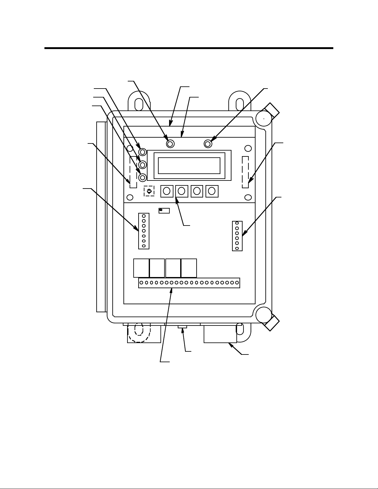
Internal Description
This section describes the internal components of the Beacon 100.
ALARM 3 Light
ALARM 2 Light
ALARM 1 Light
ACFuse,
500mA
(on Main PC
Board)
AC/DC Power
Terminal Strip
PILOT Light
ALARM 3
ALARM 2
ALARM 1
PILOT
Main PC Board
DISPLAY
UPESCAPE
Control
Buttons(4)
Display PC
Board
FAIL
ENTERDOWN
FAIL Light
DC Fuse,
1.5Amp
(on Main PC
Board)
Right Hand Terminal
Strip (Buzzer, Reset,
24VDC Out)
FAIL
Relay
Relay
Relay
Relay
Reset Switch/
External Alarm, Detector, and
Analog OutputTerminal
Strips
Buzzer
3/4" Conduit
Hub (2)
ALARM3
ALARM2
ALARM1
Figure 1: Beacon 100 Gas Monitor Component Location
Beacon 100 Gas Monitor Operator’s Manual Internal Description • 7
Page 8

Fuses
The Beacon 100 includes one AC fuse (0.5 amp) and one DC fuse (1.5 amp).
AC fuse
The AC fuse holder is underneath the display board on the left hand side near the left
edge of the main circuit board. The AC fuse protects the AC line circuitry from short
circuit or overload. The AC fuse is rated at 0.5 amps.
NOTE: The standard configuration is for 115 VAC operation. 220 VAC operation is an
optional configuration and must be specified when ordering.
DC fuse
The DC fuse is located underneath the display board on the right hand side (near the right
edge of the main circuit board). The DC fuse protects the DC line circuitry from short
circuit or overload. The DC fuse is rated at 1.5 amps.
Transformer
The transformer is at the center top of the PC Board (under the display screen). The
transformer receives the incoming AC voltage and converts it to a nominal DC voltage.
Terminal Strips
The Beacon 100 includes three terminal strips for external wiring connections. They are
located on the lower section of the main PC board just above the incoming wiring hubs,
and to the left and right edges of the main circuit board about in the middle. See Chapter
3, Installation and Start Up, for wiring procedures.
Input power terminal strip
The input power terminal strip is located below the display board on the left hand side of
the main PCB. The top three terminals are for AC power connections and ar e labeled “AC
POWER IN” on the main circuit board.
The bottom two terminal positions are for DC power connections and are labeled “12
VDC IN” on the main circuit board.
External alarm terminal strip
The 12-point external alarm terminal strip consists of the 12 left hand terminals on the
lower terminal strip located just above the wiring hubs on the bottom of the enclosure.
You connect wiring from external alarms (if applicable) to the external alarm terminal
strip. This terminal strip has common (C), normally closed (NC) and normally open (NO)
terminals for alarm 1, alarm 2, and alarm 3 connections, and also for FAIL condition.
These terminals are clearly marked on the PC board
Detector terminal strip
The 7-point detector terminal strip (Labeled 1 through 6) is directly to the right of the
external alarm terminals on the lower terminal strip. You connect wiring from the detector
head to the detector terminal strip. T erminals labeled 1, 2, 3, and 4, ar e for the wiring to the
detector head. These are also labelled “RED, WHITE, GREEN, BLACK” to correspond to
the sensor wire colors on certain sensor types. Terminals 5 and 6 are for connection of the
oxygen detector head and are labelled OXY+ and OXY -.
8 • Internal Description Beacon 100 Gas Monitor Operator’s Manual
Page 9

NOTE: See the detector head operator’s manual and the Beacon 100 Detector Head
Specification Sheet for the installed detector head to wire the detector head to the
appropriate detector terminal strip connections.
Analog Output terminal strip
The 2-point analog output terminal strip (labeled 4-20 mA out) is directly to the right of
the detector terminal connections. You connect wiring from a recording device (if
applicable) to the analog output terminal strip.
The output at the analog output terminal strip is 4 - 20 mA.
Right Hand terminal strip
The right hand terminal strip located about in the right middle of the board is used for
internal connection of the instrument buzzer and reset switch. This right hand strip also
has terminals marked “24 VDC OUT”, which can be used for powering an external pump
for certain gas detection heads.
Relays
Four relays are located just above the external wiring terminal strips. The relays are
single-pole, double-throw (SPDT) and are rated for 12 amps at 120 VAC (resistive), or 6
amps at 220 VAC. The relays are from left to right Fail, Alarm 1, Alarm 2, and Alarm 3.
NOTE: You can select normally energized or normally de-energized relays in the
Instrument Setup program. This section describes the default setting: normally
de-energized. The fail relay is factory-set as normally energized and is not
user-selectable.
Display Screen
NOTE: The display screen, status lights, and program buttons are mounted to a small
circuit board. The circuit boar d is mounted to the main cir cuit board by standof fs.
The display screen is mounted to a circuit board that is installed in front of the main
circuit board. The display screen simultaneously displays the target gas, measuring unit,
and current gas reading.
The display screen also displays messages, settings, and other data when you are
operating the instrument programs (see Chapter 4, Operation).
Status Lights
The Beacon 100 includes five status lights that indicate the current status of the monitor.
PILOT light
The PILOT light is above the display screen and to the left of the FAIL light. The green
PILOT light is on when the monitor is receiving incoming power.
FAIL light
The FAIL light is above the display screen and to the right of the PILOT light. The FAIL
light turns on when the Beacon 100 is experiencing a fail condition. A fail condition can be
caused by a failure within the monitor or detector head wired to the monitor. See Chapter
5, Maintenance, or the troubleshooting section in the detector head’s operator’s manual to
Beacon 100 Gas Monitor Operator’s Manual Internal Description • 9
Page 10

respond to a fail condition.
ALARM 1 light
The ALARM 1 light is to the left of the display screen. The ALARM 1 light turns on when
the Beacon 100 is experiencing an Alarm 1 condition (see Chapter 4, Operation).
ALARM 2 light
The ALARM 2 light is to the left of the display screen and above the ALARM 1 light. The
ALARM 2 light is on when the Beacon 100 is experiencing an Alarm 2 condition.
ALARM 3 light
The ALARM 3 light is to the left of the display screen and above the ALARM 2 light. The
ALARM 3 light turns on when the Beacon 100 is experiencing an Alarm 3 condition.
Program Buttons
The Beacon 100 includes four program buttons that allow you to enter the instrument
programs, navigate through the programs, update instrument and channel settings, and
save changes to the program settings. These buttons are located just below the display.
ESCAPE button
The ESCAPE button is below the display screen near the left side. Use the ESCAPE button
to:
• move backward through the instrument programs
• cancel changes you make in the instrument programs
• enter the Instrument Setup Program (when pressed with the DOWN button)
UP button
The UP button is to the right of the escape button below the display screen. Use the UP
button to:
• change settings within the instrument programs
DOWN button
The DOWN button is to the right of the UP button below the display screen. Use the
DOWN button to:
• change settings within the instrument programs
• enter the Channel Setup program (when pressed with the ESCAPE button)
ENTER button
The ENTER button is to the right of the DOWN button below the display screen. Use the
ENTER button to:
• move forward through the instrument programs
• save changes you make in the instrument programs.
10 • Internal Description Beacon 100 Gas Monitor Operator’s Manual
Page 11

Chapter 3: Installation and Start Up
Overview
This chapter describes procedures to mount the Beacon 100 Gas Monitor, make wiring
connections to the monitor, and start up the monitor.
WARNING: Perform all installation and start-up procedures in a “fresh air”
environment (known to be free of combustible gas, toxic gas, and of
normal oxygen content). The Beacon 100 is not in operation as a gas
monitoring system until the start-up procedure is complete.
Beacon 100 Gas Monitor Operator’s Manual Overview • 11
Page 12

Mounting the Beacon 100 Gas Monitor
Perform the following procedure to install the instrument housing at the mounting site.
1. Select the mounting site. When you select the mounting site consider the following
factors:
• Is an AC or DC power source available?
• Is there enough room to open the housing door and make wiring connections
through the conduit hubs at the bottom of the housing?
• Are the display screen and status lights visible?
2. If necessary, close and latch the housing door.
3. Position the monitor on a vertical surface at eye level (4 1/2 to 5 feet from the floor).
4. Insert 1/4 in. or 5/16 in. screws through the slots in the mounting feet at each corner
of the housing to secure the housing to the mounting surface (see Figure 3-1).
7.2
1.7
8.5
4.00
.30 X .50 Slots (4X)
Door Latches
8.88 MTG
1.9
3.03
3/4 Conduit Hub
(2X)
Figure 2: Beacon 100 Gas Monitor Outline and Mounting Dimensions
12 • Mounting the Beacon 100 Gas Monitor Beacon 100 Gas Monitor Operator’s Manual
Page 13

ACPowerIn
115 VAC,60Hz
(230VAC Optional.)
12VDC Backup
Power In
24 VDC Out,
100 mA max
Buzzer, Factory Wired
Reset Switch,
Factory Wired
ALARMDEVICEPOWER
Contact Rating Of 12 Amps
at 120VAC For Each Set Of Relay Contacts
Fail Alarm
Device
Alarm 1
Device
Alarm 2
Device
Alarm 3
Device
See Detector Head Operator's
Manual and Beacon 100 Detector
Head Specification Sheet for Wiring
Typical Wiring Shown
Recorder
Output
4-20 mA
Hot
Neutral
Ground
+
-
+
Resistive
H
AC Power Input
N
G
+
12 VDC
Input
-
-
24 VDC
OUT.
+
Buzzer
+
Reset
NO
COM
NC
NO
COM
NC
NO
COM
NC
NO
COM
NC
1RED (+ 24 V)
2WHT (FB)
3 GRN
4BLK (-)
5OX+
6 OX-
+
-
Fail
Alarm 1
Alarm 2
Alarm 3
4-20mA
Out
Figure 3: Beacon 100 Gas Monitor External Wiring Diagram
Beacon 100 Gas Monitor Operator’s Manual Mounting the Beacon 100 Gas Monitor • 13
Page 14

Wiring the Beacon 100 Gas Monitor
This section describes procedures to connect the AC power source, DC power source,
external alarm(s), recorder, and detector. See Figure 3 for a general wiring diagram of all
external wiring to the Beacon 100.
WARNING: Make all connections to the Beacon 100 before you plug in or turn on
the AC or DC power source. Before you make any wiring adjustments,
always verify that all power sources are not live.
Connecting the AC Power Source
NOTE: If you are using DC power as the primary power source, go to the next section,
“Connecting the DC Power Source”.
Perform the following procedure to connect the AC power source to the Beacon 100.
WARNING: Verify that the power source is unplugged or turned off at the power
source before you continue with this procedure.
1. Open the housing door , and locate the AC terminal strip. See Figur e 1, Beacon 100 Gas
Monitor Component Location on page 7, to assist you in locating the AC terminal
strip.
2. Guide the AC power wiring through the conduit hub on the bottom of the Beacon 100
housing.
CAUTION: Do not route power and detector wiring through the same conduit hub. The power
wiring may disrupt the transmission of the detector signal to the monitor.
3. Connect the AC line to the AC power terminal strip as shown in Figure 3 on page 13,
hot to H, neutral to N, ground to G.
Connecting the DC Power Source
WARNING: Verify that the power source is unplugged or turned off before you
continue with this procedure.
Perform the following procedure to connect the DC power source to the Beacon 100.
1. Open the housing door , and locate the DC external wiring terminal strip. See Figure 1,
Beacon 100 Gas Monitor Component Location, to assist you in locating the bottom
external wiring terminal strip.
2. Guide a DC power cord through one of the conduit hubs on the bottom of the Beacon
100 housing.
CAUTION: Do not route power and detector wiring through the same conduit hub. The power
wiring may disrupt the transmission of the detector signal to the monitor.
3. Connect the DC line to the DC power terminal strip as shown in Figure 3.
14 • Wiring the Beacon 100 Gas Monitor Beacon 100 Gas Monitor Operator’s Manual
Page 15

Connecting External Alarms
Perform the following procedure to connect external alarms to the Beacon 100.
1. Open the housing door, and locate the external alarms terminal strip. See Figure 1,
Beacon 100 Gas Monitor Component Location on page 7, to assist you in locating the
external alarms terminal strip.
2. Guide the wiring of the external alarm through one of the conduit hubs on the bottom
of the Beacon 100 housing.
CAUTION: Do not route the external alarm wiring and detector wiring through the same
conduit hub. The external alarm wiring may disrupt the transmission of the detector
signal to the Beacon 100
3. Connect the leads from the external alarm to the appropriate terminals on the external
alarm terminal strip. See Figure 3 for reference.
4. Repeat steps 2 and 3 for additional external alarms.
Connecting Recorders
Perform the following procedure to connect a recording device to the Beacon 100. The
output at the analog output terminal strip is a 4 - 20 mA signal that is proportional to the
detection range of the applicable detector.
1. Open the housing door, and locate the analog output terminal strip. See Figure 1,
Beacon 100 Gas Monitor Component Location, to assist you in locating the recorder
output terminal strip.
2. Guide the wiring from the recording device through one of the conduit hubs on the
bottom of the Beacon 100 housing.
3. Connect the leads from the recording device to the analog output terminal strip as
shown in Figure 3.
Connecting RKI Detector Heads
See the detector head operator’s manual and the detector head Beacon 100 Specification
Sheet to wire a detector head supplied by RKI Instruments, Inc. to the Beacon 100.
Connecting User-Supplied 4 to 20 mA Transmitters
Perform the following procedure to connect a 4 to 20 mA transmitter (that you supply) to
the Beacon 100.
1. Open the housing door, and locate the 1, 2, and 4 (+24V, FB, and - detector terminals
respectively) terminals on the detector terminal strip. Route the cable leading from the
transmitter through one of the conduit hubs on the bottom of the Beacon 100 housing.
2. Connect the wires from the transmitter to the detector terminal strip as follows:
• For a 2-wire transmitter connect the + wire to terminal 1 (+) and the feedback wire
(-) to terminal 2 (FB).
• For a 3-wire transmitter connect the + wire to terminal 1 (+), the - wire to terminal
4 (-), and the feedback wire to terminal 2 (FB).
Beacon 100 Gas Monitor Operator’s Manual Wiring the Beacon 100 Gas Monitor • 15
Page 16

Starting Up the Beacon 100 Gas Monitor
Perform the following procedure to place the Beacon 100 into normal operation.
1. Complete the mounting and wiring procedures described earlier in this chapter.
2. Complete all installation procedures in the detector head or user supplied 4 - 20 mA
transmitter.
3. Verify that all wiring connections are correct and secure.
4. Plug in or turn on the incoming power source (AC or DC).
NOTE: For about 100 milliseconds after power to the unit is turned on the alarm relays
will energize and then de-energize. Then all alarms will be inactive during the
remainder of the warm-up period, approximately 45 seconds. If you have alarm
devices connected to the alarm relays, do not turn on power to the alarm devices
until after this initial 100 millisecond period or unwanted alarms may occur.
5. Verify the following:
• The PILOT light on the display screen is on.
If the pilot light is not on, see the troubleshooting section in this manual and in the
detector head operator’s manual.
6. Perform the start-up procedure for the detector as described in the detector head
operator’s manual for the installed detector.
16 • Starting Up the Beacon 100 Gas Monitor Beacon 100 Gas Monitor Operator’s Manual
Page 17

Chapter 4: Operation
Overview
This chapter describes the Beacon 100 Gas Monitor in normal operation. This chapter also
describes the Beacon 100 in alarm 1, alarm 2, alarm 3, and fail conditions and suggests
response to these conditions. The Instrument Setup program is described at the end of this
chapter.
Normal Operation
Normal operation is defined as follows:
• the start-up procedure is complete.
• the Beacon 100 is not indicating an alarm 1, alarm 2, alarm 3, or fail condition.
• the Beacon 100 is not running the Instrument Setup Program
During normal operation, the Beacon 100 displays the target gas, unit of measure, and
current gas reading sensed at the gas sensor location.
The PILOT light near the display screen should be on during normal operation indicating
that the monitor is receiving incoming power. The output of the analog output terminal
strip is 4 - 20 mA and is proportional to the detection range of the detector head that is
wired to the Beacon 100.
Alarm Indications
This section describes the Beacon 100 in alarm 1, alarm 2, alarm 3, and fail conditions and
suggests response to these conditions. Table 2 lists the alarm indications for each
condition.
NOTE: The Beacon 100 includes alarm on and alarm off delay settings. The alarm
indications described in this section operate according to the default delay
settings.
Beacon 100 Gas Monitor Operator’s Manual Overview • 17
Page 18

Table 2: Visual and Audible Alarm Indications
Condition Cause Visual Indication
Alarm 1 Increasing (decreasing for O2) gas reading
at or above the alarm 1 setpoint
Alarm 2 Increasing (decreasing for O2) gas reading
at or above the alarm 2 setpoint
• ALARM 1 light is on
• Gas reading flashes
• ALARM 1 and ALARM 2
lights are on
• Gas reading flashes
Alarm 3 Increasing gas reading at or above the
alarm 3 setpoint
• ALARM 1, ALARM 2,
and ALARM 3 lights are
on*
• Gas reading flashes
Fail • Disconnected or misconnected
• FAIL light is on Steady tone
detector wiring
• Display reading below fail setpoint
• Defective components
* The ALARM 1 and ALARM 2 lights are not on for oxygen channels.
NOTE: You can select normally energized or normally de-energized relays and latching
or auto resetting alarms in the Instrument Setup program. The following sections
describe the default setting for the relays and alarms: normally de-energized and
latching respectively. The fail relay is factory-set for normally energized and is
not user-selectable.
Audible
Indication
Pulsing tone
Faster
pulsing tone
than Alarm 1
Faster
pulsing tone
than Alarm 2
Alarm 1 Condition
This section describes the audible and visual indications for an alarm 1 condition and
suggests response to an alarm 1 condition.
Alarm 1 condition indications
When the gas reading of an active channel reaches the alarm 1 setpoint, the Beacon 100
senses an alarm 1 condition. The Beacon 100 alerts you to an alarm 1 condition as follows:
• the ALARM 1 light turns on
• the gas reading in alarm 1 condition flashes
• the buzzer sounds a pulsing tone
• the alarm 1 relay energizes
Responding to an alarm 1 condition
This section suggests response to an alarm 1 condition.
1. Follow your established procedure for a low level combustible or toxic gas condition
or a decreasing oxygen content condition.
18 • Alarm Indications Beacon 100 Gas Monitor Operator’s Manual
Page 19

2. After the gas reading falls below the alarm 1 setpoint, press the reset switch to reset
the alarm 1 circuit. Resetting the alarm 1 circuit silences the buzzer, turns off the
ALARM 1 light, and de-energizes the alarm 1 relay.
NOTE: To silence the buzzer while in an alarm 1 condition, press the reset switch.
You cannot de-energize the alarm 1 relay until the gas reading falls below (above
for oxygen) the alarm 1 setpoint. Once the gas reading falls below the alarm 1
setpoint, if the reset button has been previously pressed the alarm 1 r elay will deenergize.
Alarm 2 Condition
This section describes the audible and visual indications for an alarm 2 condition and
suggests response to an alarm 2 condition.
Alarm 2 condition indications
When the gas reading of an active channel reaches the alarm 2 setpoint, the Beacon senses
an alarm 2 condition. The Beacon 100 alerts you to an alarm 2 condition as follows:
• the ALARM 2 light turns on
• the gas reading in alarm 2 condition continues to flash
• the buzzer sounds a faster pulsing tone than an alarm 1 condition
• the alarm 2 relay energizes
Responding to an alarm 2 condition
This section suggests response to an alarm 2 condition.
1. Follow your established procedure for a mid level combustible or toxic gas condition
or a severe decreasing oxygen content condition.
2. After the gas reading falls below the alarm 2 setpoint, press the reset switch to reset
the alarm circuit. Resetting the alarm circuit turns off the ALARM 2 light, and
de-energizes the alarm 2 relay.
NOTE: The alarm 2 condition cannot be silenced. The reset switch must be pressed after
the gas reading falls below the alarm 2 level in order to de-energize the alarm 2
relay.
Alarm 3 Condition
This section describes the audible and visual indications for an alarm 3 condition and
suggests response to an alarm 3 condition.
Alarm 3 condition indications
When the gas reading of an active channel reaches the alarm 3 setpoint, the Beacon 100
senses an alarm 3 condition. The Beacon 100 alerts you to an alarm 3 condition as follows:
• the ALARM 3 light turns on
• the gas reading in alarm 3 condition continues to flash (the gas reading for O2
channels begins flashing)
• the buzzer sounds a faster pulsing tone than an alarm 1 or alarm 2 condition
• the alarm 3 relay energizes
Beacon 100 Gas Monitor Operator’s Manual Alarm Indications • 19
Page 20

Responding to an alarm 3 condition
This section suggests response to an alarm 3 condition.
1. Follow your established procedure for a high level combustible or toxic gas condition
or an increasing oxygen content condition.
2. After the gas reading falls below the alarm 3 setpoint, press the reset switch to reset
the alarm 3 circuit. Resetting the alarm 3 circuit turns off the ALARM 3 light, and
de-energizes the alarm 3 relay.
NOTE: The alarm 3 condition cannot be silenced. The reset switch must be pressed after
the gas reading falls below the alarm 3 level in order to de-energize the alarm 3
relay.
Fail Condition
This section describes the audible and visual indications for a fail condition and suggests
response to a fail condition.
Fail condition indications
The Beacon 100 senses a fail condition for any of the following:
• the detector wiring is disconnected or incorrectly connected
• the display reading is below the fail setpoint
• the monitor or detector is malfunctioning
When the Beacon 100 senses a fail condition, it alerts you as follows:
• the FAIL light turns on
• the gas reading flashes
• the buzzer sounds a steady tone
• the fail relay de-energizes
Responding to a fail condition
This section suggests response to a fail condition.
1. Verify that the detector wiring is correctly and securely connected.
2. See the troubleshooting guide in the applicable detector head operator’s manual.
20 • Alarm Indications Beacon 100 Gas Monitor Operator’s Manual
Page 21

Instrument Setup Program
This section describes the Instrument Setup program. You can display and change the
following instrument settings with the Instrument Setup program.
• Calibration Settings
• Zero Suppression
• Latching or auto reset alarms
• Alarm delay on
• Alarm delay off
• Alarm level setting
• Alarm relay normally energized or de-energized
• Rising or falling alarms
Navigating through the Instrument Setup Program
Use the program buttons below the display screen to enter the program, move forwar d or
backward through the program, change settings within the program, and save or cancel
changes to the program settings. Table 3 lists the function of each program button.
Table 3: Program Button Functions for the Instrument Setup Program
Button Function
ESCAPE • Moves you backward through the program
• Cancels changes made to the program settings
• Enters the program (with the DOWN button)
UP • Updates the setting that is flashing on the
display screen
• Moves the cursor to the left or up to the next line
DOWN • Updates the setting that is flashing on the
display screen
• Moves the cursor to the right or down to the next
line
• Enters the program (with the ESCAPE button)
ENTER • Moves you forward through the program
• Saves changes made to the program settings
Beacon 100 Gas Monitor Operator’s Manual Instrument Setup Program • 21
Page 22

Running the Instrument Setup Program
This section describes how to enter the program, display and change program settings,
and save or cancel changes to the program settings.
Entering the instrument setup program
1. Open the housing door, and locate the program buttons below the display screen.
2. Press the ESCAPE and DOWN buttons simultaneously and hold for 3 seconds.
The display screen changes from the gas reading screen to a screen that gives you a
choice of CALIB or ALARMS & MISC.
3. Press the UP, or DOWN button to make the cursor blink in front of the item you wish
to enter then press the ENTER button to proceed.
If the ENTER button is pressed with the cursor in front of the CALIB indication, the
instrument will enter the calibration program. The calibration program is described in
Chapter 5: Maintenance on page 26.
If the ENTER button is pressed with the cursor in front of the ALARMS & MISC indication, the instrument will enter the Instrument Setup Program. Once into the program, you have the choice of “MISC” or “ALARMS”. Use the up and down buttons to
move the cursor in front of the desired item.
Miscellaneous Adjustments Screen
If ENTER is pressed with the cursor in front of MISC, you enter the Miscellaneous
Adjustments Screen where you can view or change the following parameters: zero
suppression, latching or auto reset alarms, alarm on delay, and alarm off delay.
• Zero suppression
The zero suppression feature helps prevent “jumpy” readings near the normal (zero)
reading. For example, if the zero suppression setting is 2.0% of full scale and full scale
is 10.0 ppm, then the Beacon 100 will display a reading of 0.0 ppm for gas readings
from -0.2 to 0.2 ppm. You can choose from a range of 0.0% to 6.0% (in 1% increments).
The default setting is 2% of scale.
T o access the zer o suppr ession setting, move the cursor in front of the ZROSUP% item
and press the ENTER button. The current zero suppr ession% of scale setting will flash
on the screen.
• To change the zero suppression setting:
1. Use the UP or DOWN button to display the setting you want.
2. Press the ENTER button to accept this new value and the value will stop
flashing. If you press ESCAPE while the value is still flashing, any change you
may have made will be cancelled and the original value will be displayed.
• Alarm logic (Latching or Auto Reset alarms)
This setting indicates how an alarm circuit is reset after the applicable alarm condition
passes. If the setting is LATCH (latching), you must press the reset switch after the
alarm condition passes to reset the alarm circuit. If the setting is AUTO (auto reset),
the alarm circuit automatically resets after the alarm condition passes. The default setting is LATCH.
22 • Instrument Setup Program Beacon 100 Gas Monitor Operator’s Manual
Page 23

NOTE: If alarm 1 is silenced when the alarm logic is set to latching, the alarm 1 relay will
de-energize after the gas reading falls below the alarm 1 setpoint
To access the alarm logic setting, move the cursor in front of the current setting,
LATCH or AUTO, and press the ENTER button.
• To update the alarm logic setting:
1. Use the UP or DOWN button to display the setting you want (either LATCH
for latching alarms, or AUTO for auto reset alarms)
2. Press the ENTER button to accept this new setting and the setting will stop
flashing. If you press ESCAPE while the setting is still flashing, any change
you may have made will be cancelled and the original setting will be
displayed.
• Alarm on delay (DLY ON)
This setting indicates the length of time that the BEACON 100 delays relay activation
when it senses an alarm 1, alarm 2, or alarm 3 condition. The audible and visible
alarm indications, the buzzer and alarm LED’s, are not delayed. You can choose from
a range of 0 Seconds to 4 Minutes (240 seconds). The default setting is 0 seconds.
To access the alarm on delay setting, move the cursor in front of DLY ON and press
the ENTER button. This will cause the current alarm on delay setting to blink (seconds).
• To update the alarm on delay setting:
1. Use the UP and DOWN buttons to display the setting you want. The setting
changes just 1 second for each press of the UP or DOWN button.
2. Press the ENTER button to accept the displayed value and it will stop
flashing. If you press ESCAPE while the setting is still flashing, any change
you may have made will be cancelled and the original setting will be
displayed.
• Alarm off delay (OFF)
This setting indicates the length of time that the BEACON 100 delays relay deactiva-
tion after an alarm 1, alarm 2, or alarm 3 condition passes. The deactivation of audible
and visible alarm indications, the buzzer and alarm LED’s, is not delayed. The You
can choose from a range of 0 Seconds to 4 Minutes (240 seconds). The default setting is
0 seconds.
To access the alarm off delay setting, move the cursor in front of OFF and press the
ENTER button. This will cause the current alarm off delay setting to blink.
• To update the alarm off delay setting:
1. Use the UP and DOWN buttons to display the setting you want. The setting
changes just 1 second for each press of the UP or DOWN button.
2. Press the ENTER button to accept the displayed value and it will stop
flashing. If you press ESCAPE while the setting is still flashing, any change
you may have made will be cancelled and the original setting will be
displayed.
• Press the ESCAPE button once to choose between MISC and ALARM, twice to
choose between CALIB and ALARM&MISC, and three times to return to normal
operation.
Beacon 100 Gas Monitor Operator’s Manual Instrument Setup Program • 23
Page 24

Alarm Adjustments Screen
If ENTER is pressed with the cursor in front of ALARM, you can choose an alarm level,
ALARM 1, ALARM 2, or ALARM 3, for which the following settings can be changed:
alarm levels, relay action (normally energized or de-energized alarms), and alarm type
(rising or falling alarms). To access any of the above settings for a particular channel,
move the cursor in front of the alarm level desired with the UP and DOWN buttons and
press ENTER. The current alarm level, relay action (NDE or NE) and alarm type (RISE or
FALL) will be displayed.
• Alarm Level
The user may set the alarm levels for the instrument to any level from zero to full
scale.
To access the alarm level, move the cursor in front of the current alarm level using the
UP and DOWN buttons and press ENTER. The current alarm level will start flashing.
The current alarm level is the number on the far right of the top display line.
• To adjust the alarm level:
1. Use the UP and DOWN buttons to adjust the setting to the desired level.
2. Press ENTER to accept the new setting and it will stop flashing. If you press
ESCAPE while the setting is still flashing, any change you may have made
will be cancelled and the original setting will be displayed.
• Relay Action
This setting indicates how the relays operate in normal and alarm conditions. If the
setting is normally de-energized, NDE, the relays energize in alarm conditions. If the
setting is normally energized, NE, the relays de-energize in alarm conditions. The
default setting is normally energized, NDE.
NOTE: The fail relay is not affected by this setting. The fail relay is factory-set as
normally energized and is not adjustable
To access the relay action setting, move the cursor in front of the current setting (NDE
or NE) using the UP and DOWN buttons and press ENTER. The current setting will
start flashing.
• To update the relay action setting (normally energized or normally de-energized
relays):
1. Use the UP and DOWN buttons to change the setting to the relay action to the
desired setting, NDE or NE.
2. Press ENTER to accept the new setting and it will stop flashing. If you press
ESCAPE while the setting is still flashing, any change you may have made
will be cancelled and the original setting will be displayed.
• Alarm Type
This setting indicates whether the alarm is a rising or falling alarm. If it is a rising
alarm, then the alarm activates when the reading increases above the alarm point. If it
is a falling alarm, then the alarm activates when the reading decreases below the
alarm point.
To access the alarm type setting, move the cursor in front of the current setting (RISE
or FALL) with the UP and DOWN buttons and press ENTER. The current setting will
start to flash.
24 • Instrument Setup Program Beacon 100 Gas Monitor Operator’s Manual
Page 25

• To update the alarm type setting:
1. Use the UP and DOWN buttons to change the current setting to the desired
setting, RISE or FALL.
2. Press ENTER to accept the new setting and it will stop flashing. If you press
ESCAPE while the setting is still flashing, any change you may have made
will be cancelled and the original setting will be displayed.
Returning to Normal Operation
Press ESCAPE four times to return to normal operation.
Beacon 100 Gas Monitor Operator’s Manual Instrument Setup Program • 25
Page 26

Chapter 5: Maintenance
Overview
This chapter describes use of the Calibration Program and corrective maintenance
procedures for the Beacon 100. It includes a troubleshooting guide for problems you may
encounter with the Beacon 100. Procedures to replace components of the Beacon 100 ar e at
the end of this chapter.
Calibration Program
The Calibration Program is used to calibrate the detector head installed on the Beacon 100.
The Beacon 100 supports either a direct connect (internal amp) or 4-20 mA transmitter
(remote amp) detector head.
• Direct connect detector head.
If a direct connect detector head is installed, then all calibration adjustments are made
at the Beacon 100 after calibration gas is applied to the detector . When a direct connect
detector head is installed, the detector head may be installed at a remote location, or a
detector may be installed directly to the Beacon 100 in one of the conduit hubs on the
bottom.
• 4-20 mA transmitter detector head.
If a 4-20 mA transmitter detector head is installed, then all calibration adjustments ar e
made at the detector head after calibration gas is applied to the detector. A 4 - 20 mA
transmitter detector head is installed remotely from the Beacon 100.
WARNING: The Beacon 100 is not an active gas monitoring device during the
calibration procedure.
Entering the Calibration Program
1. Assemble the calibration kit. See the operator’s manual for the installed detector head
for calibration procedures specific to that detector head.
2. Open the Beacon 100 housing door and locate the program buttons below the display
screen.
3. Press ESCAPE and DOWN buttons simultaneously and hold for 3 seconds to enter
the Instrument Setup Program.
The display screen changes from the gas reading to a scr een that gives you a choice of
CALIB or ALARMS & MISC.
26 • Overview Beacon 100 Gas Monitor Operator’s Manual
Page 27

NOTE: Once you leave normal operation and enter this screen, if any alarm conditions
were occurring when you left normal operation, they will be retained by the
Beacon 100 until you return to normal operation. If an alarm condition no longer
exists when you return to normal operation, press the reset switch to reset
alarms.
4. Press the UP or DOWN button to make the cursor blink in front of CALIB, then press
the ENTER button to enter the Calibration Program.
The display screens that follow and the calibration procedure will depend on which
type of detector head is installed on the Beacon 100: 4-20 mA transmitter, non-oxygen
type direct connect, or oxygen type direct connect. Use the appropriate set of instructions below to calibrate the detector head.
Calibrating a 4-20 mA Transmitter Detector Head
If a 4 - 20 mA detector head is installed, use the following calibration procedure.
1. A screen appears which displays “CALIB MODE” on the top line and the current
reading below it.
NOTE: No reading adjustments can be made at the Beacon 100. All zero and span
adjustments must be made at the detector head. The purpose of entering the
calibration program is to avoid unwanted alarms during calibration.
2. Verify that the detector head is in a fresh-air environment. (If necessary, use a zeroemission air cylinder, also known as zero air, to introduce a fresh-air sample when
adjusting the zero reading below.)
3. Adjust the detector head’s zero (fresh air reading for oxygen) reading. See the
detector head’s instruction manual for instructions on how to adjust the zero reading
(fresh air reading for oxygen).
4. Apply calibration gas to the detector head’s detector and adjust the detector head’s
span reading (zero reading for oxygen). See the detector head’s instruction manual for
instructions on how to adjust the span (zero reading for oxygen) reading.
5. Allow time for the gas reading to return to normal and then press ESCAPE two times
to return to normal operation.
NOTE: If you do not allow the gas reading to return to normal, then unwanted alarms
may occur.
Calibrating a Direct Connect Detector Head, Non-Oxygen Type
If a non-oxygen type direct connect detector head is installed, such as combustible gas or
carbon monoxide, is installed, use the following calibration procedure.
1. The ZERO/SPAN screen appears and allows you to choose between ZERO and
SPAN. If necessary, press the UP button to make the cursor blink in front of ZERO,
then press ENTER. The screen will indicate the current reading.
2. Verify that the detector head is in a fresh-air environment.
If the detector head is not in a fresh air environment, use a zero-emission air calibra-
tion cylinder, also known as zero air, to introduce a fresh-air sample before continuing. See the detector head operator’s manual for instructions to apply zero air.
Beacon 100 Gas Monitor Operator’s Manual Calibration Program • 27
Page 28

3. Press the ENTER button to perform a zero adjust. The screen will momentarily show
WAIT and then indicate ZERO COMPLETE.
4. Press ESCAPE to return to the ZERO/SPAN screen
5. Use the DOWN button to make the cursor blink in front of SPAN. Press ENTER
6. The screen will display the concentration of calibration gas that it expects when you
perform the span operation.
Use the UP or DOWN button to set the concentration to the same level that is in the
calibration cylinder being used, then press the ENTER button to accept it. The screen
will display the current reading.
7. Apply the calibration gas to the detector. See the detector head instruction manual for
instructions on how to apply gas to the detector.
8. After applying calibration gas for the required amount of time, press the ENTER
button to perform a span adjust. The screen will momentarily show WAIT and then
indicate SPAN COMPLETE.
9. Press the ESCAPE button twice to return to the screen that allows you to choose
between ZERO and SPAN.
10. Allow enough time for the gas reading to return to normal and then press ESCAPE
two times to return to normal operation.
NOTE: If you do not allow the gas reading to return to normal, then unwanted alarms
may occur.
Calibrating a Direct Connect Oxygen Detector Head
If an oxygen direct connect detector head is installed, use the following calibration
procedure.
1. The ZERO/SPAN screen appears and allows you to choose between ZERO and
SPAN. If necessary, press the DOWN button to make the cursor blink in front of
SPAN, then press ENTER.
2. The screen will display the concentration of oxygen that it expects when you perform
the span operation. It will show CAL GAS = 20.9.
Usually fresh air is used and the default concentration is 20.9%. If you are using a
cylinder to span the sensor, make sure the concentration shown on this screen
matches the oxygen concentration in your cylinder . If necessary, use the UP or DOWN
button to set the concentration to the correct level, then press the ENTER button to
accept it.
3. The screen will display the current reading. If necessary, apply gas to the oxygen
detector as described in the detector head operator’s manual.
4. Press the ENTER button to perform a span adjust. The screen will momentarily show
WAIT and then indicate SPAN COMPLETE.
5. Press ESCAPE twice to return to the ZERO/SPAN screen
6. If necessary, press the UP button to make the cursor blink in front of ZERO. Press
ENTER. The screen will indicate the current reading.
7. Apply 100% nitrogen gas to the oxygen detector. See the detector head instruction
manual for instructions on how to apply gas to the detector.
8. After applying calibration gas for the required amount of time, press the ENTER
28 • Calibration Program Beacon 100 Gas Monitor Operator’s Manual
Page 29

button to perform a zero adjust. The screen will momentarily show WAIT and then
indicate ZERO COMPLETE.
9. Allow enough time for the gas reading to return to normal and then press ESCAPE
three times to return to normal operation.
NOTE: If you do not allow the gas reading to return to normal, then unwanted alarms
may occur.
Preventive Maintenance
Preventive maintenance of the Beacon 100 consists of daily, monthly, and quarterly
procedures to ensure that the detector reading remains on zero (20.9 for oxygen) in fresh
air and is responsive to gas. See the operator’s manual for the detector installed on the
Beacon 100 for detector preventive maintenance schedules.
Troubleshooting
The troubleshooting guide describes symptoms, probable causes, and recommended
action for problems you may encounter with the Beacon 100.
NOTE: This troubleshooting guide describes controller problems only. See the
Troubleshooting guide in the detector head operator’s manual for problems you
may encounter with the detectors.
No Power
Symptoms
• The pilot lights is off.
• The display screen is blank.
Probable causes
• The power wiring is disconnected or misconnected.
• The AC or DC fuse is blown.
• The display cable is disconnected.
Recommended action
1. Verify that the wiring to the power source is correct and secure.
2. At the Beacon 100, verify that the wiring to the AC terminal strip is correct and secur e.
3. Check the continuity of the AC and DC fuse.
4. Verify that the display cable is connected. The display (ribbon) cable plugs into
connectors on the bottom of the display board and on the main board below and to
the left of the DC fuse.
5. If the power difficulties continue, contact RKI Instruments, Inc., for further
instruction.
Beacon 100 Gas Monitor Operator’s Manual Preventive Maintenance • 29
Page 30

Frequent or Suspect Alarms
Symptoms
• The Beacon 100 alerts you to frequent or suspect alarms, but the detector’s fresh air
readings remain on zero (20.9 for oxygen).
Probable causes
• The Beacon 100 is experiencing false readings due to Radio Frequency Interference
(RFI) or Electromagnetic Interference (EMI).
• The detector wiring is disconnected, misconnected, or intermittent.
Recommended action
1. Verify that the detector wiring is properly shielded (see the detector operator’s
manual).
2. Verify that the detector wiring is correct and secure.
3. Verify that power and detector wiring is routed through separate conduit hubs on the
bottom of the Beacon 100 housing.
4. Increase the alarm on delay setting in the Instrument Setup program (see Chapter 4,
Operation).
5. If the frequent or suspect alarm difficulties continue, contact RKI Instruments, Inc., for
further instruction.
Flickering Display Readings
Symptoms
• The display readings flicker often.
Probable causes
• The Beacon 100 is experiencing false readings due to Radio Frequency Interference
(RFI) or Electromagnetic Interference (EMI).
• The zero suppression setting is too low.
• The display screen is malfunctioning.
Recommended action
1. Verify that the detector wiring is properly shielded (see the detector operator’s
manual).
2. Verify that the detector wiring is correct and secure.
3. Verify that power and detector wiring is routed through separate conduit hubs on the
bottom of the Beacon 100 housing.
4. Increase the zero suppression setting in the Instrument Setup pr ogram (see Chapter 4,
Operation).
5. If the display difficulties continue, contact RKI Instruments, Inc., for further
instruction.
30 • Troubleshooting Beacon 100 Gas Monitor Operator’s Manual
Page 31

The Buzzer is not Working Properly
Symptoms
• The buzzer does not sound an audible alarm when the Beacon 100 goes into an alarm
1, alarm 2, alarm 3, or fail condition.
• The buzzer sounds weak or broken.
Probable causes
• The buzzer is disconnected.
• The buzzer is connected incorrectly.
• The buzzer is malfunctioning.
Recommended action
1. Open the housing door of the Beacon 100, then verify that the buzzer wiring to the
right hand terminal strip is correct and secure. The red wire goes to BUZ + and the
black wire goes to BUZ -.
2. If the buzzer difficulties continue, contact RKI Instruments, Inc., for further
instruction.
The Reset Switch is not Working Properly
Symptoms
• The buzzer is not silenced when you press the reset switch.
NOTE: You cannot use the reset switch to silence the buzzer if the unit is in an alarm 2,
alarm 3, or fail condition.
• The applicable alarm circuit is not reset when an alarm condition passes and you
press the reset switch.
Probable causes
• The reset switch is disconnected.
• The reset switch is connected incorrectly.
• The reset switch is malfunctioning.
Recommended action
1. Open the housing door of the Beacon 100, then verify that the reset switch wiring to
the RESET terminals on the right hand terminal strip is correct and secure.
2. If the reset switch difficulties continue, contact RKI Instruments, Inc., for further
instruction.
Beacon 100 Gas Monitor Operator’s Manual Troubleshooting • 31
Page 32

Replacing Components
This section describes procedures to replace the fuses. To replace other components of the
Beacon 100, contact RKI Instruments, Inc., for further information.
Replacing the AC Fuse
This section describes the procedure to replace the AC fuse.
1. Unplug all incoming power to the Beacon 100 at the power source end.
2. Open the housing door of the Beacon 100.
3. Remove the four screws which secure the display PCB to the four standoffs that are
mounted to the main PCB.
4. Move the display PCB aside to gain access to the AC fuse holder.
5. Remove the AC fuse from its clip holder.
CAUTION: Verify that the replacement fuse is the same type and rating as the fuse you are
replacing. See the Parts List at the end of this manual for the RKI part number.
6. Install the appropriate replacement fuse in the fuse holder.
7. Reinstall the display PCB with the four screws.
8. Plug in or turn on all incoming power to the Beacon 100 at the power source end.
9. Verify that the PILOT light is on.
10. Close and secure the housing door.
Replacing the DC Fuse
This section describes the procedure to replace the DC fuse.
1. Turn off or unplug all incoming power to the Beacon 100 at the power source end.
2. Open the housing door of the Beacon 100
3. Remove the four screws which secure the display PCB to the four standoffs that are
mounted to the main PCB.
4. Move the display PCB aside to gain access to the DC fuse holder.
5. Remove the DC fuse from the clip holder.
CAUTION: Verify that the replacement fuse is the same type and rating as the fuse you are
replacing. See the parts list at the end of this manual for the RKI part number.
6. Install the appropriate replacement fuse into the clip holder.
7. Reinstall the display PCB with the four screws.
8. Plug in or turn on all incoming power to the Beacon 100 at the power source end.
9. Verify that the PILOT light is on.
10. Close and secure the housing door.
Beacon 100 Gas Monitor Operator’s Manual Replacing Components • 32
Page 33

Parts List
The table below lists the part numbers and descriptions for replacement parts and
accessories offered for the Beacon 100 Gas Monitor.
Table 4: Parts List for the Beacon 100 Gas Monitor
Part No. Description
18-0107RK Conduit Hub (3/4 in.)
43-0440RK Reset Switch
43-4138RK AC Fuse, 115V (1/2 amp; 250V)
43-4145RK DC Fuse (1.5 amps; 250V
52-1016RK Buzzer
71-0035RK Beacon 100 Gas Monitor Operator’s Manual (this document)
Beacon 100 Gas Monitor Operator’s Manual Parts List • 33
 Loading...