

Page 1

Find Quality Products Online at: sales@GlobalTestSupply.com
www.GlobalTestSupply.com
Page 2

Warranty
RKI Instruments, Inc. warrants gas alarm equipment sold by us to be free from defects in
materials and workmanship, and performance for a period of one year from date of shipment from
RKI Instruments, Inc. Any parts found defective within that period will be repaired or replaced, at
our option, free of charge. This warranty does not apply to those items which by their nature are
subject to deterioration or consumption in normal service, and which must be cleaned, repaired, or
replaced on a routine basis. Examples of such items are:
Warranty is voided by abuse including mechanical damage, alteration, rough handling, or repairs
procedures not in accordance with the instruction manual. This warranty indicates the full extent
of our liability, and we are not responsible for removal or replacement costs, local repair costs,
transportation costs, or contingent expenses incurred without our prior approval.
Absorbent cartridges Batteries
Pump diaphragms and valves Filter elements
Fuses
THIS WA RR AN T Y IS EXPRESSLY IN LIEU OF ANY AND ALL OTHER WARRANTIES
AND REPRESENTATIONS, EXPRESSED OR IMPLIED, AND ALL OTHER
OBLIGATIONS OR LIABILITIES ON THE PART OF RKI INSTRUMENTS, INC.
INCLUDING BUT NOT LIMITED TO THE WA R RA NT Y OF MERCHANTABILITY OR
FITNESS FOR A PARTICULAR PURPOSE. IN NO EVENT SHALL RKI
NSTRUMENTS, INC. BE LIABLE FOR INDIRECT, INCIDENTAL, OR
I
CONSEQUENTIAL LOSS OR DAMAGE OF ANY KIND CONNECTED WITH THE USE
OF ITS PRODUCTS OR FAILURE OF ITS PRODUCTS TO FUNCTION OR OPERATE
PROPERLY.
This warranty covers instruments and parts sold to users only by authorized distributors, dealers,
and representatives as appointed by RKI Instruments, Inc.
We do not assume indemnification for any accident or damage caused by the operation of this gas
monitor and our warranty is limited to replacement of parts or our complete goods.
Find Quality Products Online at: sales@GlobalTestSupply.com
www.GlobalTestSupply.com
Page 3

Table of Contents
Chapter 1: Introduction . . . . . . . . . . . . . . . . . . . . . . . . . . . . . . . . . . . . . . . . . . . . . . . . . . . . . . . . 6
Overview. . . . . . . . . . . . . . . . . . . . . . . . . . . . . . . . . . . . . . . . . . . . . . . . . . . . . . . . . . . . . . . 6
About the SDM-6000 . . . . . . . . . . . . . . . . . . . . . . . . . . . . . . . . . . . . . . . . . . . . . . . . . . . . . 6
System Requirements . . . . . . . . . . . . . . . . . . . . . . . . . . . . . . . . . . . . . . . . . . . . . . . . . . . . . 7
About This Manual . . . . . . . . . . . . . . . . . . . . . . . . . . . . . . . . . . . . . . . . . . . . . . . . . . . . . . . 7
Cautions & Safety Information. . . . . . . . . . . . . . . . . . . . . . . . . . . . . . . . . . . . . . . . . . . . . . 8
Specifications . . . . . . . . . . . . . . . . . . . . . . . . . . . . . . . . . . . . . . . . . . . . . . . . . . . . . . . . . . . 8
How to Build a System . . . . . . . . . . . . . . . . . . . . . . . . . . . . . . . . . . . . . . . . . . . . . . . . . . . . 9
Chapter 2: Description . . . . . . . . . . . . . . . . . . . . . . . . . . . . . . . . . . . . . . . . . . . . . . . . . . . . . . . . 10
Overview. . . . . . . . . . . . . . . . . . . . . . . . . . . . . . . . . . . . . . . . . . . . . . . . . . . . . . . . . . . . . . 10
SDM-6000 Components . . . . . . . . . . . . . . . . . . . . . . . . . . . . . . . . . . . . . . . . . . . . . . . . . . 10
Touch Screen. . . . . . . . . . . . . . . . . . . . . . . . . . . . . . . . . . . . . . . . . . . . . . . . . . . . . 11
Status LED . . . . . . . . . . . . . . . . . . . . . . . . . . . . . . . . . . . . . . . . . . . . . . . . . . . . . .16
Instrument Cradle . . . . . . . . . . . . . . . . . . . . . . . . . . . . . . . . . . . . . . . . . . . . . . . . .16
Gas In/Gas Out Cover . . . . . . . . . . . . . . . . . . . . . . . . . . . . . . . . . . . . . . . . . . . . .16
Left Panel Components. . . . . . . . . . . . . . . . . . . . . . . . . . . . . . . . . . . . . . . . . . . . . 17
Mating Slave Connections . . . . . . . . . . . . . . . . . . . . . . . . . . . . . . . . . . . . . . . . . . 19
Exhaust Fitting . . . . . . . . . . . . . . . . . . . . . . . . . . . . . . . . . . . . . . . . . . . . . . . . . . . 20
Air Filter and Exhaust Tubing . . . . . . . . . . . . . . . . . . . . . . . . . . . . . . . . . . . . . . .21
Connection Brackets . . . . . . . . . . . . . . . . . . . . . . . . . . . . . . . . . . . . . . . . . . . . . . .21
Accessories Included in Various Bundles. . . . . . . . . . . . . . . . . . . . . . . . . . . . . . . . . . . . . 22
AC Adapter . . . . . . . . . . . . . . . . . . . . . . . . . . . . . . . . . . . . . . . . . . . . . . . . . . . . . .22
USB Cable. . . . . . . . . . . . . . . . . . . . . . . . . . . . . . . . . . . . . . . . . . . . . . . . . . . . . . .23
Ethernet Cable . . . . . . . . . . . . . . . . . . . . . . . . . . . . . . . . . . . . . . . . . . . . . . . . . . .23
SD Card and SD to USB Reader. . . . . . . . . . . . . . . . . . . . . . . . . . . . . . . . . . . . . .23
Demand Flow Regulator. . . . . . . . . . . . . . . . . . . . . . . . . . . . . . . . . . . . . . . . . . . . 23
Calibration Tubing . . . . . . . . . . . . . . . . . . . . . . . . . . . . . . . . . . . . . . . . . . . . . . . .24
Calibration Cylinder. . . . . . . . . . . . . . . . . . . . . . . . . . . . . . . . . . . . . . . . . . . . . . .24
Find Quality Products Online at: sales@GlobalTestSupply.com
www.GlobalTestSupply.com
Page 4

Optional Accessories, Not Included in Any Bundles . . . . . . . . . . . . . . . . . . . . . . . . . . . . 24
SV-3 . . . . . . . . . . . . . . . . . . . . . . . . . . . . . . . . . . . . . . . . . . . . . . . . . . . . . . . . . . . .24
Printer. . . . . . . . . . . . . . . . . . . . . . . . . . . . . . . . . . . . . . . . . . . . . . . . . . . . . . . . . . 24
Wall Mounting Brackets . . . . . . . . . . . . . . . . . . . . . . . . . . . . . . . . . . . . . . . . . . . . 24
Chapter 3: Preparing to Use the SDM-6000. . . . . . . . . . . . . . . . . . . . . . . . . . . . . . . . . . . . . . . 25
Overview. . . . . . . . . . . . . . . . . . . . . . . . . . . . . . . . . . . . . . . . . . . . . . . . . . . . . . . . . . . . . . 25
Installing the SDM-PC2 Docking Station PC Controller Program . . . . . . . . . . . . . . . . . 25
Setup for Chlorine Testing . . . . . . . . . . . . . . . . . . . . . . . . . . . . . . . . . . . . . . . . . . . . . . . . 27
Connecting Multiple SDM-6000s Together, Optional . . . . . . . . . . . . . . . . . . . . . . . . . . . 28
Connecting the SV-3, Optional . . . . . . . . . . . . . . . . . . . . . . . . . . . . . . . . . . . . . . . . . . . . . 32
Connecting the Printer, Optional . . . . . . . . . . . . . . . . . . . . . . . . . . . . . . . . . . . . . . . . . . . 33
Hardware Assembly . . . . . . . . . . . . . . . . . . . . . . . . . . . . . . . . . . . . . . . . . . . . . . . . . . . . . 33
Wall Mounting the SDM-6000, Optional . . . . . . . . . . . . . . . . . . . . . . . . . . . . . . . . . . . . . 34
Connecting Calibration Gas, No SV-3 Attached. . . . . . . . . . . . . . . . . . . . . . . . . . . . . . . . 38
Connecting Calibration Gas, SV-3 Attached. . . . . . . . . . . . . . . . . . . . . . . . . . . . . . . . . . . 41
Setting Basic Operational Parameters in the Config Menu . . . . . . . . . . . . . . . . . . . . . . . 43
Bump Test Parameters . . . . . . . . . . . . . . . . . . . . . . . . . . . . . . . . . . . . . . . . . . . . .44
Calibration Parameters . . . . . . . . . . . . . . . . . . . . . . . . . . . . . . . . . . . . . . . . . . . .49
Inlet Parameters . . . . . . . . . . . . . . . . . . . . . . . . . . . . . . . . . . . . . . . . . . . . . . . . . .53
Date, Time, and Date/Time Format . . . . . . . . . . . . . . . . . . . . . . . . . . . . . . . . . . .57
Language . . . . . . . . . . . . . . . . . . . . . . . . . . . . . . . . . . . . . . . . . . . . . . . . . . . . . . .59
Password. . . . . . . . . . . . . . . . . . . . . . . . . . . . . . . . . . . . . . . . . . . . . . . . . . . . . . . . 61
Setting Detailed Parameters Using the PC Program. . . . . . . . . . . . . . . . . . . . . . . . . . . . . 63
Launching the PC Controller Program and Connecting an SDM-6000 . . . . . . .64
Accessing the SDM Configuration Window . . . . . . . . . . . . . . . . . . . . . . . . . . . . . 64
Updating the Data Logger Settings . . . . . . . . . . . . . . . . . . . . . . . . . . . . . . . . . . . 66
Updating the Power Saving Settings . . . . . . . . . . . . . . . . . . . . . . . . . . . . . . . . . .68
Updating the Expiration Date Settings. . . . . . . . . . . . . . . . . . . . . . . . . . . . . . . . . 69
Updating the Automatic Execution Settings . . . . . . . . . . . . . . . . . . . . . . . . . . . . .70
Updating the Cylinders Settings . . . . . . . . . . . . . . . . . . . . . . . . . . . . . . . . . . . . . .71
Setting Up LAN Connectivity . . . . . . . . . . . . . . . . . . . . . . . . . . . . . . . . . . . . . . . . . . . . . 81
Find Quality Products Online at: sales@GlobalTestSupply.com
www.GlobalTestSupply.com
Page 5

Chapter 4: Operation . . . . . . . . . . . . . . . . . . . . . . . . . . . . . . . . . . . . . . . . . . . . . . . . . . . . . . . . . 90
Overview. . . . . . . . . . . . . . . . . . . . . . . . . . . . . . . . . . . . . . . . . . . . . . . . . . . . . . . . . . . . . . 90
Automatically Initiated Tests . . . . . . . . . . . . . . . . . . . . . . . . . . . . . . . . . . . . . . . . . . . . . . 90
Turning on an SDM-6000 System . . . . . . . . . . . . . . . . . . . . . . . . . . . . . . . . . . . . . . . . . . 90
Bump Testing . . . . . . . . . . . . . . . . . . . . . . . . . . . . . . . . . . . . . . . . . . . . . . . . . . . . . . . . . . 95
Calibration . . . . . . . . . . . . . . . . . . . . . . . . . . . . . . . . . . . . . . . . . . . . . . . . . . . . . . . . . . . . 99
Alarm Check . . . . . . . . . . . . . . . . . . . . . . . . . . . . . . . . . . . . . . . . . . . . . . . . . . . . . . . . . . 103
Troubleshooting . . . . . . . . . . . . . . . . . . . . . . . . . . . . . . . . . . . . . . . . . . . . . . . . . . . . . . . 106
Charging a GX-6000 in a Docking Station. . . . . . . . . . . . . . . . . . . . . . . . . . . . . . . . . . . 108
Recharging a Battery Pack After Performing a Test . . . . . . . . . . . . . . . . . . . . . 108
Recharging a Battery Pack Without Performing Any Operations . . . . . . . . . . .109
Batteries Too Drained for Standalone Operation. . . . . . . . . . . . . . . . . . . . . . . . 110
Bump Test, Calibration, and Alarm Check Records . . . . . . . . . . . . . . . . . . . . . . . . . . . . 111
Available Memory in the SD Card . . . . . . . . . . . . . . . . . . . . . . . . . . . . . . . . . . . 111
Test Record Files. . . . . . . . . . . . . . . . . . . . . . . . . . . . . . . . . . . . . . . . . . . . . . . . . 111
Transferring Record Files to a Computer. . . . . . . . . . . . . . . . . . . . . . . . . . . . . . 112
Chapter 5: Viewing Test Data in a Text Editor . . . . . . . . . . . . . . . . . . . . . . . . . . . . . . . . . . . 113
Chapter 6: Importing Data Into the SDM-PC2 PC Program. . . . . . . . . . . . . . . . . . . . . . . . 115
Overview. . . . . . . . . . . . . . . . . . . . . . . . . . . . . . . . . . . . . . . . . . . . . . . . . . . . . . . . . . . . . 115
Importing from an SD Card . . . . . . . . . . . . . . . . . . . . . . . . . . . . . . . . . . . . . . . . . . . . . . 115
Importing Using the LAN Network . . . . . . . . . . . . . . . . . . . . . . . . . . . . . . . . . . . . . . . . 118
Viewing Imported Data. . . . . . . . . . . . . . . . . . . . . . . . . . . . . . . . . . . . . . . . . . . . . . . . . . 121
Exiting the Program . . . . . . . . . . . . . . . . . . . . . . . . . . . . . . . . . . . . . . . . . . . . . . . . . . . . 121
Chapter 7: Spare Parts List . . . . . . . . . . . . . . . . . . . . . . . . . . . . . . . . . . . . . . . . . . . . . . . . . . 122
Appendix A: Setting the Actual Gas Selection Box . . . . . . . . . . . . . . . . . . . . . . . . . . . . . . . . 125
One-PID-Sensor GX-6000s . . . . . . . . . . . . . . . . . . . . . . . . . . . . . . . . . . . . . . . . . . . . . . 126
Two-PID-Sensor GX-6000s . . . . . . . . . . . . . . . . . . . . . . . . . . . . . . . . . . . . . . . . . . . . . . 127
Changing a PID Short Name . . . . . . . . . . . . . . . . . . . . . . . . . . . . . . . . . . . . . . . . . . . . . 129
CAUTION: Read and understand this manual before using the SDM-6000. Also read and
understand the GX-6000 Operator’s Manual.
Find Quality Products Online at: sales@GlobalTestSupply.com
www.GlobalTestSupply.com
Page 6

Chapter 1: Introduction
Overview
This chapter briefly describes the SDM-6000 Docking Station and the SDM-PC2 Docking Station
PC Controller Program. This chapter also describes the SDM-6000 Docking Station Standalone
Configuration Operator’s Manual (this document). Table 1 at the end of this chapter lists the
SDM-6000’s specifications.
About the SDM-6000
The SDM-6000 Docking Station is an advanced, reliable system that can charge, bump test,
calibrate, alarm check, and provide test records for up to 10 GX-6000 portable gas monitors at
once. It is designed to save the test records to an SDHC card (standalone functionality) or to be
connected directly to a computer (PC controlled functionality). If test records are stored to an
SDHC card while operating in the standalone configuration, the PC Controller Program can then
be used with a Windows-based personal computer to retrieve test data files from the SDHC card
or from the computer’s hard drive if the files have been transferred to the hard drive from the
SDHC card. If you are using the PC Controller Program while operating in the PC controlled
configuration, you may retrieve instrument data, bump test, calibrate, and alarm check
instruments. Instrument information and data for each instrument can be viewed directly using the
PC Controller Program and can be printed from the PC Controller Program. For instructions to
use the SDM-6000 in the PC Controlled Configuration, see the SDM-6000 Docking Station PC
Controlled Configuration Operator’s Manual.
The purpose of this manual is to explain how to set up and use the SDM-6000 in Standalone
configuration. It also explains how to use the sections of the PC Controller Program associated
with Standalone use. You will learn how to:
• install and launch the PC Controller Program
• prepare the SDM-6000 for use
• perform a bump test
• perform a calibration
• perform an alarm check
• download instrument data to the SD card
• import instrument data, bump test, calibration, and alarm check records to the PC Controller
Program’s database
• use the SDM-6000 to charge a GX-6000
6 • Chapter 1: Introduction
Find Quality Products Online at: sales@GlobalTestSupply.com
www.GlobalTestSupply.com
Page 7
CAUTION: The GX-6000 detects oxygen deficiency and elevated levels of oxygen,
combustible gases, carbon monoxide, and hydrogen sulfide, all of which can be
dangerous or life threatening. When using the GX-6000, you must follow the
instructions and warnings in the GX-6000 Operator’s Manual to assure proper
and safe operation of the instrument and to minimize the risk of personal injury.
CAUTION: The operator of this instrument is advised that if the equipment is used in a
manner not specified in this manual, the protection provided by the equipment
may be impaired.
System Requirements
To use the SDM-PC2 Docking Station PC Controller Program, your personal computer must meet
the following requirements:
• Operating Systems: Windows
• Processor: IBM
• Memory: 32 MB RAM minimum
• Hard Disk Space: 32 MB minimum
• Available USB Port
• SD Card Slot (recommended)
About this Manual
The SDM-6000 Docking Station Standalone Configuration Operator’s Manual uses the following
conventions for notes, cautions, and warnings.
NOTE: Describes additional or critical information.
CAUTION: Describes potential damage to equipment.
WARNING: Describes potential danger that can result in injury or death.
®
7, Windows® 8, Windows® 10.
®
compatible PC running Pentium® 2 processor or equivalent minimum
Chapter 1: Introduction • 7
Find Quality Products Online at: sales@GlobalTestSupply.com
www.GlobalTestSupply.com
Page 8
Cautions & Safety Information
• Use only polyurethane sample tubing with the SDM-6000. Consult RKI Instruments, Inc.
for other materials.
• Do not subject the SDM-6000 to infrared or intense light. This may cause communication
errors.
• Do not expose the SDM-6000 to water.
• Do not subject the SDM-6000 to any hard impact.
Specifications
Table 1: Specifications
Input Power 24 VDC
Environmental Conditions • For Indoor Use Only
• 0° C to 40° C, below 95% Relative Humidity, NonCondensing
Applicable Instrument GX-6000
Memory Capacity Dependent on capacity of installed SDHC card
Record Size 1.1 KB (bump test + calibration + alarm check)
Maximum Number of Records
Saved
Number of Calibration Gas
Cylinders
Standard Accessories • Instruction Manual*
Available Accessories •AC Adapter
Dependent on capacity of installed SDHC card
• SV-3 not connected: Up to three calibration gas cylinders per
bump test or calibration at a time
• SV-3 connected: Up to six calibration gas cylinders per bump
test or calibration at a time
• SDM-PC2 Docking Station PC Controller Software*
• Inlet Air Filter
• 10 Foot Long Exhaust Tube
• Connection Brackets
• USB Cable, Type A to Type B
• Ethernet Cable
• SDHC Card and SD to USB Reader
• Demand Flow Regulator
• 3-Foot Long Calibration Tubing
• Calibration Gas Cylinder
•SV-3
•Printer
• Wall Mounting Brackets
•CO
Scrubber
2
8 • Chapter 1: Introduction
Find Quality Products Online at: sales@GlobalTestSupply.com
www.GlobalTestSupply.com
Page 9

How to Build a System
Various accessories are included with the SDM-6000 depending on what SDM-6000 bundle is
ordered. See the table below for what’s included with each basic bundle. Other bundles are
available that include different calibration gas cylinders than the 4-gas mix included in the 81SDM6000-04.
For example, if you have 5 separate single-station systems where none of the 5 stations are
connected together, each system will need 1 each of the starred items which means you will have
a total of 5 each of the starred items. For this system, you would need to order 5 81-SDM6000-01
bundles, 5 81-SDM6000-03 bundles, or 5 81-SDM6000-04 bundles depending on additional
accessories desired.
If you have 1 multi-station system with 5 SDM-6000s connected together, you will only need 1
each of the starred items in order to operate all 5 SDM-6000s. For this system, you would need to
order 1 81-SDM6000-02 bundle and 4 81-SDM6000 bundles. Any additional accessories would
need to be ordered separately.
Bundle Part Numbers
Included Items
Docking Station X X X X X
Exhaust Tube, 10 ft. X X X X X
USB Cable* X X X X
Ethernet Cable, 5 ft.* X X X X
Single-Station AC Adapter*
Multi-Station AC Adapter*
SDHC Card with SD to USB Reader* X X X X
Demand Flow Regulator X X
Calibration Tubing, 3 ft. X X X X
Calibration Cylinder Holder X
Calibration Cylinder** X
a
b
81-SDM6000
81-SDM6000-01
XXX
81-SDM6000-02
X
81-SDM6000-03
81-SDM6000-04
* Each system needs only one each of these.
*a
Used only for single-station systems.
*b
Used only for multi-station systems.
** Type of calibration cylinder depends on bundle ordered.
Chapter 1: Introduction • 9
Find Quality Products Online at: sales@GlobalTestSupply.com
www.GlobalTestSupply.com
Page 10

Chapter 2: Description
Instrument
Cradle
Gas In/Gas
Out Cover
Status LED
STATUS
Touch Screen
Instruction Label
Figure 1: SDM-6000 Component Location
Overview
This section describes the SDM-6000 docking station’s components, various accessories that may
or may not be included depending on what bundle was ordered, and optional accessories that are
not included in any bundles.
SDM-6000 Components
The SDM-6000 consists of the touch screen, status LED, instrument cradle, gas in/gas out cover,
left panel, mating slave connections, exhaust fitting, air filter, exhaust tubing, and connection
brackets.
10 • Chapter 2: Description
Find Quality Products Online at: sales@GlobalTestSupply.com
www.GlobalTestSupply.com
Page 11
Touch Screen
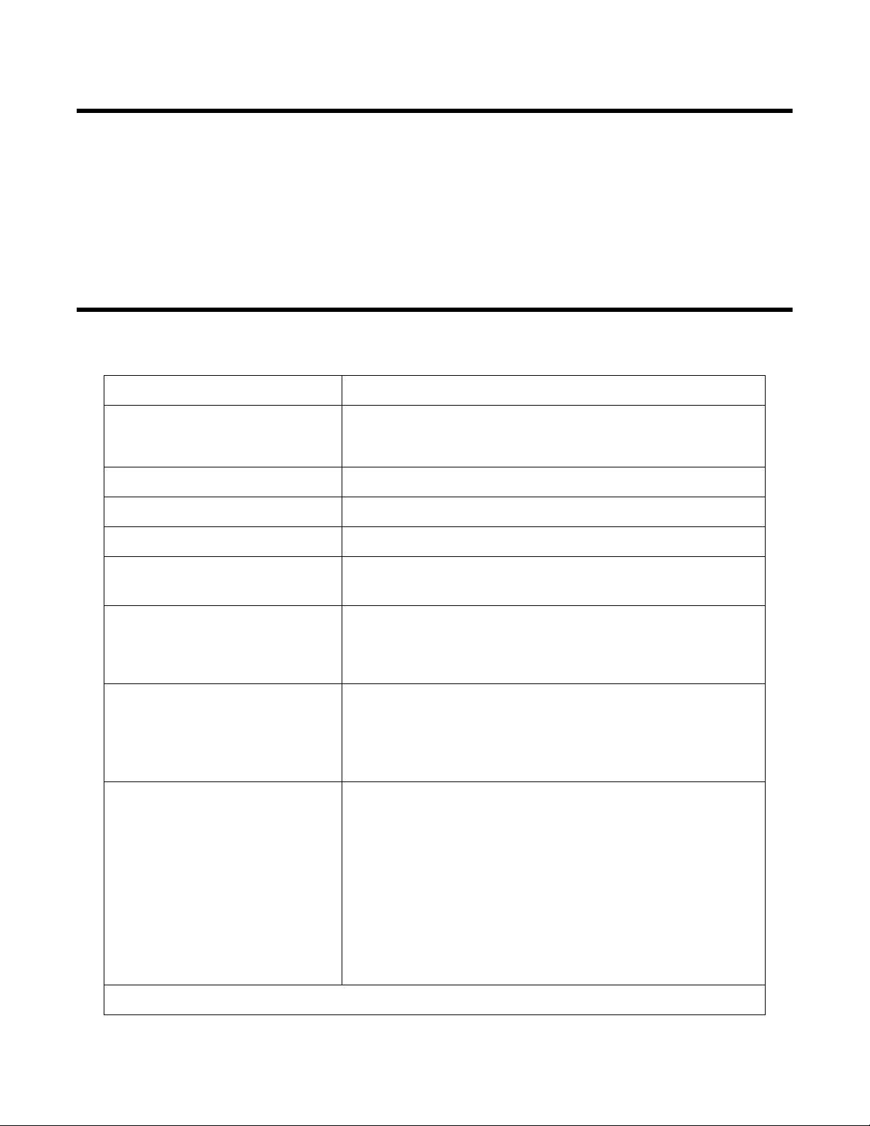
Figure 2: Single SDM-6000 System Touchscreen
Figure 3: Multi-SDM-6000 System Touchscreens
Master Touchscreen
Slave Touchscreen
The LCD touch screen is located at the bottom front of the SDM-6000. In a single SDM-6000
system, the touch screen includes the Function and Unit Tabs. In a multi-SDM-6000 system, the
master (leftmost) SDM-6000’s touch screen includes the Function and Unit Tabs and any slave
SDM-6000s’ touch screens only display the Unit Tab information. The Function and Unit tabs are
described below in "Function Tab" and "Unit Tab".
Find Quality Products Online at: sales@GlobalTestSupply.com
www.GlobalTestSupply.com
Chapte r 2 : De s criptio n • 11
Page 12

Function Tab
Figure 4: Function Tab
The Function Tab allows the user to:
• initiate a bump test
• initiate a calibration
• initiate an alarm check
• set operational parameters
It is present on the touch screen of a single SDM-6000 system and on the touch screen of the
master (leftmost) SDM-6000 in a multi-SDM-6000 system. It has the same appearance in both
systems. The text field above the BUMP and CAL buttons shows instrument or station status.
SD Card Logo
The SD card logo in the bottom left corner of the Function Tab indicates whether an SD card is
inserted in the SD card slot and the status of an inserted SD card.
Table 2: SD Card Logo Colors
SD Card Logo Color Meaning
Gray No SD card inserted.
Green More than 20% of the SD card’s memory is available.
Yellow Less than 20% but more than 1 MB (approximately 946 tests) of
the SD card’s memory is available.
Red Less than 1 MB (approximately 946 tests) of the SD card’s
memory is available.
Cylinder Logo
The cylinder logo in the bottom left corner of the Function Tab indicates the expiration status of
the calibration cylinders. In order to set up the expiration status, the docking station must be
connected to the PC Controller Program and the cylinder information entered into the Cylinders
Tab. If the docking station is never connected to the PC Controller Program to enter the cylinder
information, then the cylinder icon will always be grey. The table below lists all of the possible
12 • Chapter 2: Description
Find Quality Products Online at: sales@GlobalTestSupply.com
www.GlobalTestSupply.com
Page 13

colors for the cylinder logo and describes their meaning.
Table 3: Cylinder Logo Colors
Cylinder Color Meaning
Grey Expiration date more than 10 days away OR cylinder informa-
tion not set up with PC Controller Program
Yellow Expiration date for one or more cylinders is less than 10 days
away
Red Expiration date for one or more cylinders is today or has already
passed
Station/Instrument Indicator Squares
The ten squares along the bottom of the Function Tab are the Station/Instrument Indicators. They
represent up to ten SDM-6000s and GX-6000s in an SDM-6000 system from left to right. In a
single SDM-6000 system only the leftmost indicator is functional. In a multi-station system, the
leftmost indicator represents the master station and the rest of the indicators represent additional
stations in the system. Colors and icons are used with the indicators to convey SDM-6000 and
GX-6000 status and test and calibration results
If an indicator color is light grey, the same color as the background of the Function Tab, there is
not an SDM-6000 installed in the system for that position. If an indicator color is white with no
icon, an SDM-6000 is installed in that position and the corresponding SDM-6000 has no
instrument connected to it. If an indicator is a color other than light grey and an icon appears in it,
then the corresponding SDM-6000 has an instrument installed and connected to it.
Table 4: Docking Station Indicator Background Colors
Background Color Meaning
White • If no icon is showing, indicates that corresponding SDM-6000
is operating normally
• If icon is showing, indicates that corresponding SDM-6000 is
operating normally and connected instrument is not due for
calibration, inlet assignments are correct, and gas in/gas out
cover is engaged
Orange Calibration due in 10 days or less on connected instrument
Red Calibration due on connected instrument
Yellow Inlet assignment error for connected instrument
Dark Grey Gas in/gas out cover not engaged on connected instrument
Chapte r 2 : De s criptio n • 13
Find Quality Products Online at: sales@GlobalTestSupply.com
www.GlobalTestSupply.com
Page 14

Table 5: Docking Station Indicator Icons
Icon Meaning
None GX-6000 is not connected.
GX-6000 is connected and Unit Tab’s Active box is selected.
GX-6000 is connected and Unit Tab’s Active box is not
selected.
Bump test, calibration, or alarm check in process.
Test passed.
Test failed.
Datalogging information being downloaded.
Charging.
GX-6000 problem detected.
14 • Chapter 2: Description
Find Quality Products Online at: sales@GlobalTestSupply.com
www.GlobalTestSupply.com
Page 15
Unit Tab
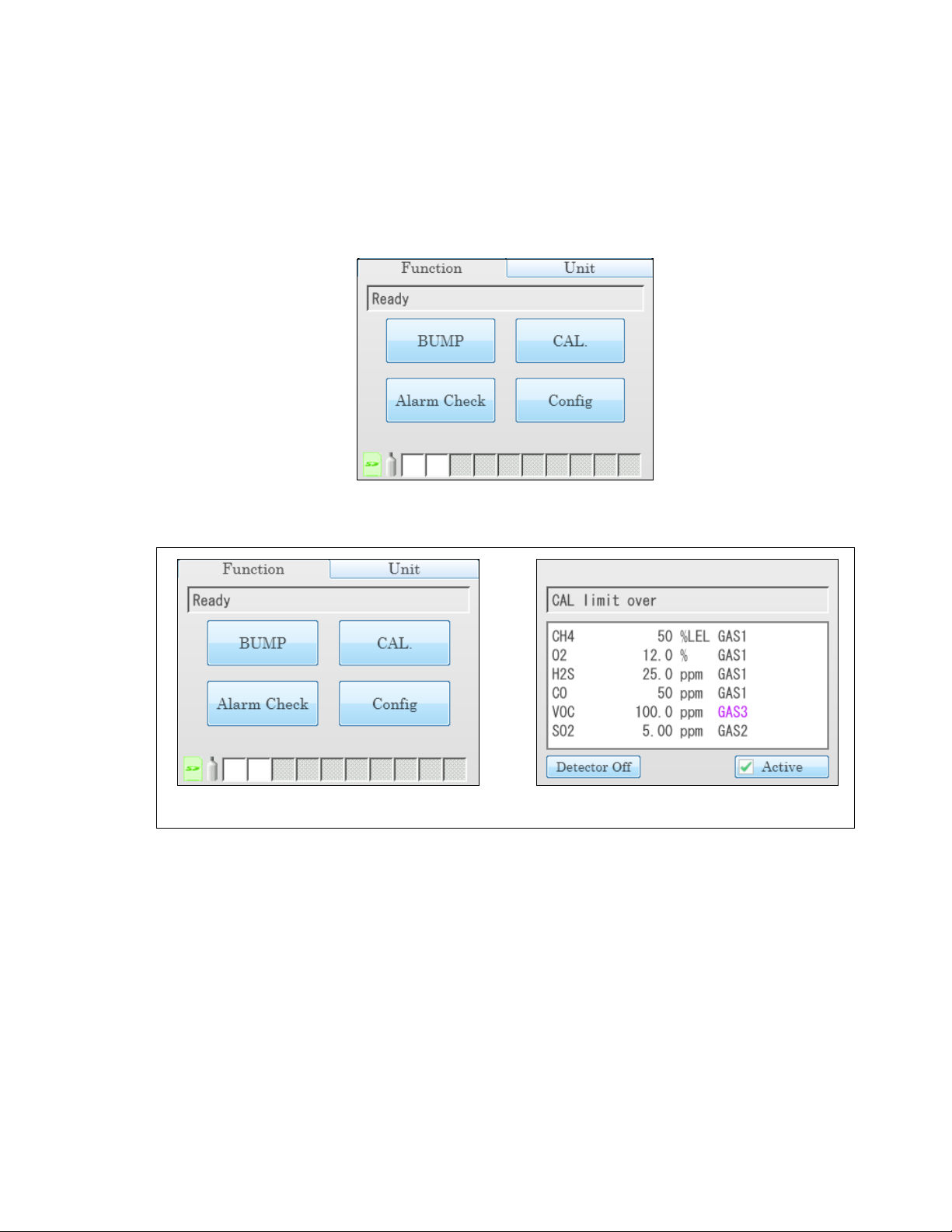
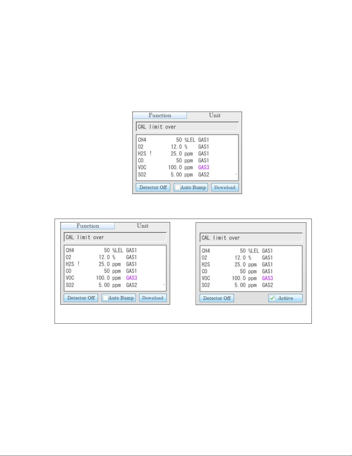
Figure 5: Unit Tab, Single SDM-6000 System
Figure 6: Unit Tab, Multi-SDM-6000 System
Master SDM-6000
Slave SDM-6000
The Unit Tab shows the gas combination of a connected GX-6000 along with calibration gas
concentration values and the pass/fail status of any tests. Its appearance varies slightly depending
on whether the SDM-6000 is a single station system, the master (leftmost) station in a multistation system, or a slave station in a multi-station system. The text field above the gas
combination which shows instrument or station status and the Detector On/Detector Off button
in the lower left which turns the GX-6000 on and off are common to each variation of the Unit
Tab.
If any of the connected instrument’s sensors are in a sensor life warning condition, a “!” will
appear to the right of the gas name.
When Actual Gas is selected for a PID channel, the gas inlet name on the SDM-6000’s Unit Tab
turns pink. When Actual Gas is deselected for a PID cylinder, the gas inlet name on the SDM6000’s Unit tab is black. Gas inlet names for all other types of sensors (standard 4-gas, ESS-03,
and IR) are always black, regardless of Actual Gas selection.
The Auto Bump selection box appears at the bottom of the screen only in a single station system.
It can be selected or deselected. If selected, a bump test will automatically begin as soon as an
Find Quality Products Online at: sales@GlobalTestSupply.com
www.GlobalTestSupply.com
Chapte r 2 : De s criptio n • 15
Page 16

instrument is connected regardless of whether or not a bump test is due. If deselected, a bump test
will not automatically begin when an instrument is connected. In a multi-station system, the Auto
Bump selection box will not appear.
The Active selection box appears in the lower right corner of the screen in a multi-station system
and includes or excludes an instrument from any testing. It appears on both the master and slave
stations.
The Download button appears in the lower right corner of the screen in a single station system
and in the lower left corner of the master station’s screen in a multi-station system. It allows you
to manually download instrument data from the instrument to an SD card.
Status LED
The Status LED is located to the right of the touch screen. The table below summarizes the
meaning of the LED’s different colors.
Table 6: Status LED Colors
Status LED Color Meaning
Solid Green No GX-6000 installed
Blinking Green GX-6000 installed and IrDA communication established
Blinking Orange Charging
Solid Orange Charging complete OR SDM-6000 starting up
Solid Red SDM-6000 problem detected
Instrument Cradle
The instrument cradle is a recessed area in the middle of the SDM-6000 that is designed to accept
the GX-6000. Insert the GX-6000 in the instrument cradle with the belt clip facing out before you
perform a bump test, calibration, alarm check or charge a GX-6000. Follow the instructions in this
manual and at the center of the instrument cradle for installing the GX-6000. An infrared (IR) port
at the rear of the panel lines up with the GX-6000’s IR port when it is inserted in the cradle and is
used to communicate with the GX-6000. Charging contacts in the bottom of the cradle line up
with the GX-6000’s charging contacts.
Gas In/Gas Out Cover
The red gas in/gas out cover mates to the GX-6000’s inlet and exhaust fittings and routes
calibration gas to and from the GX-6000. The cover is spring loaded. To connect the cover to the
GX-6000, push it down until it touches the GX-6000 and then release it. It should lock into place.
To release the cover, push it toward the GX-6000 and then release it. It should return to its
unconnected position at the top of the SDM-6000.
16 • Chapter 2: Description
Find Quality Products Online at: sales@GlobalTestSupply.com
www.GlobalTestSupply.com
Page 17

Left Panel Components
PC
PRINTERPRINTER
LAN
ON
OFF
USB PC Connector
SD Card Slot
Power Jack
USB Printer Connector
On/Off Switch
LAN Connector
DC24V
GAS Fittings
AIR Fitting
Electrical Connector
Figure 7: Left Panel Component Location
The SDM-6000’s left panel includes the SD card slot, the USB PC connector, the USB printer
connector, the LAN connector, the on/off switch, the power jack, an electrical connector, and the
sample fittings.
SD Card Slot
The SD card slot at the top of the left side of the SDM-6000 allows for the installation of an
SDHC card. The SDM-6000’s data files are saved to the SD card. If an SD card is not installed, no
data will be saved during testing.
Chapte r 2 : De s criptio n • 17
Find Quality Products Online at: sales@GlobalTestSupply.com
www.GlobalTestSupply.com
Page 18

USB PC Connector
A type B USB connection allows for the SDM-6000 to be connected to a PC using a Type A to
Type B USB cable. Connection to a PC is necessary for setting up the LAN function and for using
the SDM-6000 in its PC controlled configuration. This manual explains how to set up the LAN
function but does not cover PC controlled configuration.
USB Printer Connector
The USB printer connector allows for the optional printer accessory to be connected to the SDM-
6000.
NOTE: The SDM-6000 only supports the Seiko Instruments, Inc. DPU-S245 USB
printer. See “Printer” on page 24 for more information.
LAN Connector
The LAN connector allows for the SDM-6000 to be connected to a building’s network using an
Ethernet cable. This function allows for the SD card’s data to be downloaded to a computer
connected to the same network.
On/Off Switch
The white on/off switch turns the station on or off. Push the top of the switch toward the station to
turn it on. Push the bottom of the switch toward the station to turn it off.
Power Jack
The round power jack is located below the on/off switch. The plug on the end of the AC adapter
cable mates to it.
Electrical Connector
The black electrical connector allows for an electrical connection to another SDM-6000 or to an
SV-3.
Sample Fittings
Four sample fittings are located on the left side of the SDM-6000. The AIR fitting is the rightmost
fitting and the GAS fittings are arranged in a column to the left of the AIR fitting. The bottom to
top order is GAS1, GAS 2, and GAS 3. All four fittings accept 3/16 inch ID tubing.
18 • Chapter 2: Description
Find Quality Products Online at: sales@GlobalTestSupply.com
www.GlobalTestSupply.com
Page 19

Mating Slave Connections
Mating
Sample
Fittings,
Plugged
Panel RemovedPanel In Place
Mating
Electrical
Connection
Panel
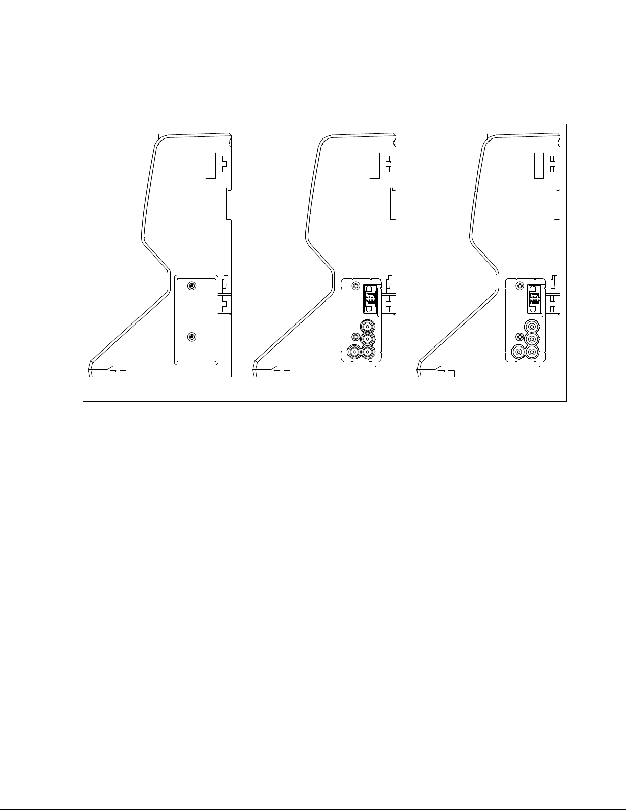
Figure 8: Right Panel Component Location
The right side of the SDM-6000 is shipped from the factory with a small panel attached to it with
two screws. That panel should remain in place if the SDM-6000 is being used alone or if it is the
right-most station in a bank of connected stations. The panel needs to be removed in order to
connect another SDM-6000 to it. Beneath the panel is a mating electrical connection and plugged
mating sample fitting connections.
Chapte r 2 : De s criptio n • 19
Find Quality Products Online at: sales@GlobalTestSupply.com
www.GlobalTestSupply.com
Page 20

Exhaust Fitting
Figure 9: Back Panel Component Location
Exhaust Fitting
An exhaust fitting is located on the SDM-6000’s back panel. It allows routing of the exhausted
calibration gas to a convenient location. This fitting accepts 5/16 inch ID tubing. Even though the
exhaust gas can be routed to an area to be safely dispersed, the docking station should still be
installed in a well ventilated area.
20 • Chapter 2: Description
Find Quality Products Online at: sales@GlobalTestSupply.com
www.GlobalTestSupply.com
Page 21

Air Filter and Exhaust Tubing
Exhaust Tubing, 5/16 Inch
ID,10 feet
Particle Filter for Air Inlet
Figure 10: Air Filter & Exhaust Tubing
A cylindrical particle filter with a short length of tubing is supplied with the SDM-6000 for
installation to the AIR fitting on the back panel. The filter keeps particulate contamination out of
the docking station.
A 10 foot length of 5/16 inch ID polyurethane tubing is provided for connection to the exhaust
fitting on the back panel to allow routing of the exhaust to a location such as an open window
where the exhaust can disperse.
WARNING: Do not use an exhaust tube that is longer than 15 feet. The increased flow
restriction caused by a longer tube may affect gas response and cause
inaccurate calibration and bump test results.
Connection Brackets
Each SDM-6000 is provided with 3 connection brackets that are used to mechanically connect
one SDM-6000 to another.
Find Quality Products Online at: sales@GlobalTestSupply.com
Chapte r 2 : De s criptio n • 21
www.GlobalTestSupply.com
Page 22

Accessories Included in Various Bundles
To Power Jack
on SDM-6000
Left Panel
Figure 11: Single-Station AC Adapter
To Power Jack on
SDM-6000 Left Panel
Figure 12: Multi-Station AC Adapter
This section describes all of the accessories that are included as standard with the SDM-6000,
depending on the SDM-6000 bundle purchased. These include: AC adapter, Type A to Type B
USB cable, Ethernet cable, SD card, SD to USB reader, demand flow regulator, calibration
tubing, and a calibration cylinder. You do not need 1 of each of these accessories for every SDM6000 in your installation but every installation needs 1 of each accessory. See pg.9 for information
about what SDM-6000 bundles include these items.
AC Adapter
Single-Station AC Adapter
The single-station AC adapter is a wall plug style adapter with a 5 foot cable. The end of the cable
has a plug that connects to the SDM-6000’s power jack. The AC adapter is rated 100 - 240 VAC
input, 24 VDC 0.63 A output.
Multi-Station AC Adapter
The multi-station AC adapter is a larger adapter with a separate power cord and a plug that
connects to the SDM-6000’s power jack. The adapter is intended to be used when more than 1
SDM-6000 are connected together. Only the master SDM-6000 needs to be plugged into power.
The AC adapter is rated 100 - 240 VAC input, 24 VDC 4.17 A output.
22 • Chapter 2: Description
Find Quality Products Online at: sales@GlobalTestSupply.com
www.GlobalTestSupply.com
Page 23

USB Cable
Figure 13: USB Cable
A Type A to Type B USB cable is used to connect the SDM-6000 to a PC which is required for
setting up the LAN connectivity function of the SDM-6000 or for using the SDM-6000 in the PC
Controlled configuration. If you have a multi-station system, the USB cable only needs to be
plugged into the master (leftmost) station.
Ethernet Cable
A 5 foot length of black Ethernet cable allows for the LAN connectivity function of the SDM6000 to be used. One end of the cable is plugged into the LAN port on the left side of the SDM6000 and the other end is plugged into one of the building’s network ports. If you have a multistation system, the Ethernet cable only needs to be plugged into the master (leftmost) station.
SD Card and SD to USB Reader
The SDHC card needs to be installed in the SD card slot on the left side of the SDM-6000 in order
for data to be saved. If you have a multi-station system, the SD card only needs to be inserted into
the master (leftmost) station’s SD card slot.
The SDHC card can be directly inserted into a computer’s SD card slot if the computer is
equipped with one. If the computer does not have an SD card slot, the provided SD to USB reader
must be used.
Demand Flow Regulator
The demand flow regulator is screwed into the calibration gas cylinder and allows the SDM-6000
to draw gas from the cylinder when the regulator is connected to the SDM-6000 using the 3 feet
of calibration tubing.
Chapte r 2 : De s criptio n • 23
Find Quality Products Online at: sales@GlobalTestSupply.com
www.GlobalTestSupply.com
Page 24

Calibration Tubing
A 3 foot length of 3/16 inch ID polyurethane tubing is provided with bundles that include a
demand flow regulator. This calibration tubing is used to connect the regulator to gas fitting on the
left side of the SDM-6000 or on the left side of the SV-3.
Calibration Gas Sample Tubing, 3/16
Inch ID, 3 feet
Figure 14: Calibration Tubing
Calibration Cylinder
The calibration gas cylinder must be used to calibrate the applicable sensors in a GX-6000. The
particular calibration gas cylinder provided depends on which bundle is ordered.
Optional Accessories, Not Included in Any Bundles
SV-3
The SV-3 increases the number of calibration cylinders that can be used with the SDM-6000 from
3 to 6. It connects to the sample fittings and electrical connector on the left side of the SDM-6000.
If you have multiple SDM-6000s connected together, the SV-3 will be installed on the left-most
SDM-6000.
The SV-3 comes with 2 connection brackets that are used to mechanically connect the SV-3 to the
left-most SDM-6000.
Printer
The printer supported by the SDM-6000 is the Seiko Instruments, Inc. DPU-S245 USB printer. It
allows for quick printing of bump test or calibration results. The printer comes with an AC
adapter and power cord, a battery pack, a USB cable, and a roll of paper. It is connected to the
SDM-6000 via the USB Printer connection on the left side of the SDM-6000.
NOTE: For questions about the printer, contact at
contact.html.
Wall Mounting Brackets
The SDM-6000 can be mounted to the wall, if desired, using 3 mounting brackets. See pg.34 for a
description of how many wall mounting brackets are needed depending on how many SDM6000s are in your system.
24 • Chapter 2: Description
Find Quality Products Online at: sales@GlobalTestSupply.com
www.GlobalTestSupply.com
Page 25

Chapter 3: Preparing to Use the SDM-6000
Overview
Setting up the SDM-6000 for use includes: installing the SDM-PC2 Docking Station PC
Controller Program, connecting multiple SDM-6000s together (optional), connecting the SV-3
(optional), connecting the printer (optional), assembling the hardware, wall mounting the station
(optional), connecting calibration gas, setting operational parameters, and setting up the LAN
connectivity (optional). Instructions to complete each of these tasks is in this section.
Although a single SDM-6000 or a bank of SDM-6000s does not need to be connected to the PC
Controller Program for Standalone operation, the PC Controller Program is needed to import and
view data and to access some SDM-6000 setup parameters.
Installing the SDM-PC2 Docking Station PC Controller Software
NOTE: The PC Controller Program is not required for Standalone operation but is
needed to import and view data and to access some setup parameters that cannot
be accessed in the SDM-6000’s Config Menu.
1. Launch Windows®.
2. Exit from all applications and open windows.
3. Go to www.rkiinstruments.com/sdm6000.
4. Click on the Download tab.
5. Click the SDM-PC2 PC Controller Software link.
6. A .zip file will begin to download. Select whether you want to open or save the .zip file.
7. Extract the contents of the .zip file.
8. Double click the setup.exe file.
9. The SDM-PC2 Docking Station PC Controller InstallShield Wizard comes up to guide you
through installation. Click Next to proceed to the License Agreement window.
10. Read the license agreement and click the agreement acceptance selection box, then click
Next to proceed to the Customer Information window.
11. Enter a user name and organization and select if you want to install the program for all users
on the computer or just for your user account, then click Next to proceed to the Destination
Folder window.
Chapter 3: Preparing to Use the SDM-6000 • 25
Find Quality Products Online at: sales@GlobalTestSupply.com
www.GlobalTestSupply.com
Page 26

Figure 15: Device Driver Installation
12. The default installation folder (C:\Program Files\SDM-PC2\) is displayed. If you want to
install the software in the default folder continue with step 13. If you want to install the
software in a different location, click Change and choose a new installation folder and then
continue with step 13.
13. Click Next to proceed to the Ready to Install the Program window.
14. Review the installation settings. If they are OK, click Install and the installation process will
begin. If you want to change installation settings, click Back and change them to the desired
settings.
15. During software installation, the installation program may find newer versions of Windows
files on your computer than those in the downloaded .zip file. If this happens, the installation
software will ask you if you want to keep these newer files. Click Ye s to do so.
16. A Device Driver Window will appear prompting you to install necessary drivers. You cannot
continue the installation without installing the drivers.
17. Click Next to install the drivers. The Wizard will find the appropriate drivers.
26 • Chapter 3: Preparing to Us e the SDM-6000
Find Quality Products Online at: sales@GlobalTestSupply.com
www.GlobalTestSupply.com
Page 27
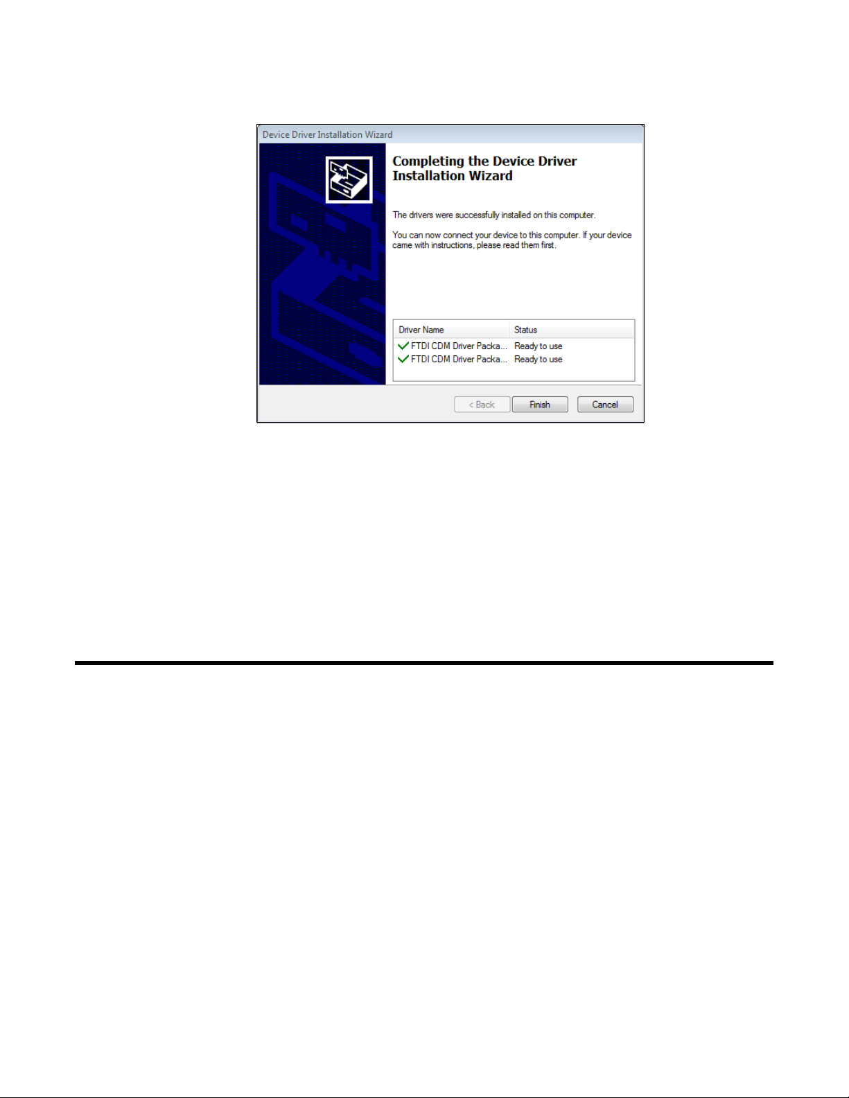
18. Click Finish once the drivers are successfully installed.
Figure 16: Finish Device Driver Installation
The installation will continue.
19. Follow the on-screen instructions to complete software installation.
20. To complete the driver installation, ensure that your docking station (or the master docking
station if you plan to have a bank of them) are connected to your computer.
21. Turn on the docking station by flipping the power switch to the ON position.
22. The first time an SDM-6000 is turned on after being connected to the computer, the SDM6000 needs some time to be recognized by the computer. The status bar will indicate that the
drivers are being configured and will alert you when the SDM-6000 is ready to use.
Setup for Chlorine Testing
There are 5 things to keep in mind when using the SDM-6000 for chlorine bump testing or
calibration.
1. Use 5 ppm Cl2.
2. Dedicate a regulator for Cl2 use. DO NOT USE A Cl2 REGULATOR FOR ANY OTHER
GAS.
3. Do not use an SV-3.
4. SDM-6000s that can be used with Cl2 are marked with a label that says “For Use With Cl2”.
If your SDM-6000 does not have a label indicating that it’s appropriate for use with Cl2, do
not use that SDM-6000 to test Cl2.
Chapter 3: Preparing to Use the SDM-6000 • 27
Find Quality Products Online at: sales@GlobalTestSupply.com
www.GlobalTestSupply.com
Page 28

Figure 17: SDM-6000 Setup for Cl2 Testing
STATUSSTATUSSTATUS
STATUS
For Use With Cl2
STATUSSTATUS
STATUS
STATUS
Cl2 Calibration
Non-Cl2 Calibration
Non-Cl2 Calibration
For Use With Cl2
Cl2 Calibration
Non-Cl2 Calibration
5. If you have a bank of SDM-6000s, the Cl2 SDM-6000 MUST be the first dock in the bank.
Connecting Multiple SDM-6000s Together
Up to 10 SDM-6000s can be connected together. The leftmost SDM-6000 is the master station
and the remaining stations are slave stations. If you remove the leftmost SDM-6000 from the
setup, the station that is now the leftmost station becomes the master but does not retain any of the
settings that the old master had.
CAUTION: If you have a Cl2 SDM-6000, it MUST be the first dock in your bank.
1. Be sure that the SDM-6000s are not connected to power.
2. For every station except the one that will be located on the far right side of the bank:
a. Unscrew the two screws that retain the panel on the right side of the station. The screws
are not captive. Be sure not to lose them.
b. Pull the panel away from the SDM-6000.
28 • Chapter 3: Preparing to Us e the SDM-6000
Find Quality Products Online at: sales@GlobalTestSupply.com
www.GlobalTestSupply.com
Page 29
c. Use needle nosed pliers to remove the clear plugs that are installed in the four mating
Figure 18: Panel and Plug Removal
Panel In Place Panel Removed Plugs Removed
sample fittings.
d. Save the panel, the screws, and the four plugs in a safe place.
3. Starting with the two left-most stations, line up the mating electrical connections and sample
fitting connections and push the two stations together until the housings are touching.
4. Add stations to the right side of the bank using the same procedure. The last station installed
should be the one that still has a panel on the right side.
Chapter 3: Preparing to Use the SDM-6000 • 29
Find Quality Products Online at: sales@GlobalTestSupply.com
www.GlobalTestSupply.com
Page 30

Figure 19: Connecting SDM-6000s Together, Back Panel
5. Use the provided metal connection brackets and screws to secure the two connection points
on each side of the SDM-6000’s back panel and on the bottom of the SDM-6000 to each
other.
30 • Chapter 3: Preparing to Us e the SDM-6000
Find Quality Products Online at: sales@GlobalTestSupply.com
www.GlobalTestSupply.com
Page 31
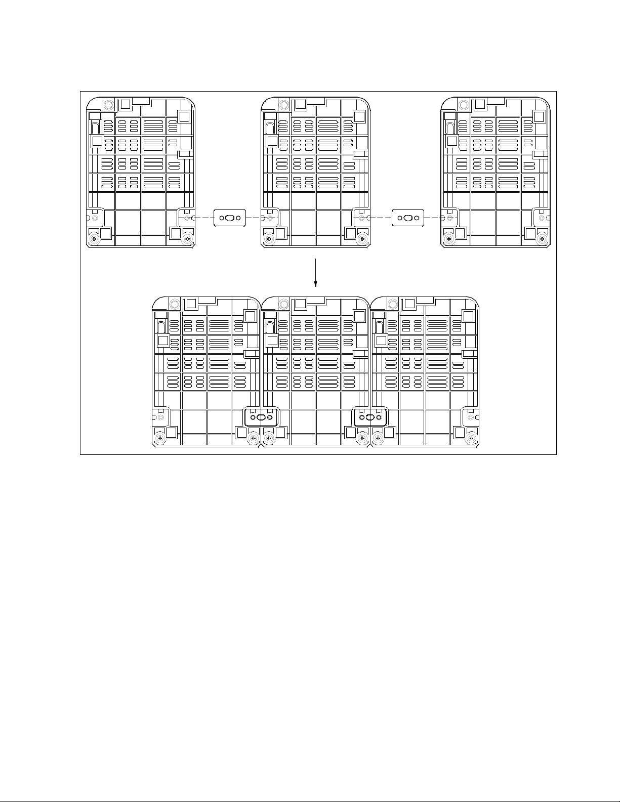
Figure 20: Connecting SDM-6000s Together, Bottom Panel
Chapter 3: Preparing to Use the SDM-6000 • 31
Find Quality Products Online at: sales@GlobalTestSupply.com
www.GlobalTestSupply.com
Page 32

Connecting the SV-3, Optional
Figure 21: Connecting the SV-3
Bottom Panel
Back P anel
CAUTION: Do not connect an SV-3 to an SDM-6000 that will be used for Cl2 testing.
1. Be sure that the SDM-6000(s) are not connected to power.
2. Line up the mating electrical connection and mating sample fitting connections on the SV-3
with the electrical connector and sample fittings on the left side of the left-most SDM-6000.
3. Push the SV-3 toward the SDM-6000 until the housings are touching.
4. Use the provided metal connection brackets and screws to secure the back and bottom of the
SV-3 to the SDM-6000.
32 • Chapter 3: Preparing to Us e the SDM-6000
Find Quality Products Online at: sales@GlobalTestSupply.com
www.GlobalTestSupply.com
Page 33

Connecting the Printer, Optional
1. If you want to power the printer with the battery pack, install the battery pack.
2. If you want to power the printer with AC power, plug the printer AC adapter’s wall plug into
a wall AC socket.
3. Connect the AC adapter to the printer’s power jack using the provided cord.
4. Connect one end of the printer’s USB cable into the printer’s USB connection. Plug the other
end of the printer’s USB cable into the USB printer connector on the left side of the SDM-
6000. Be sure to use the USB cable provided with the printer. The USB cable provided with
the SDM-6000 does not have appropriately sized USB connections for the printer.
NOTE: If you have any problems setting up the printer, contact Seiko Instruments, Inc. at
http://www.sii.co.jp/sps/eg/contact.html.
Hardware Assembly
The hardware assembly consists of connecting the AC adapter, installing the air filter, and
connecting the exhaust tubing. Perform the following to complete the hardware assembly:
1. Place the SDM-6000(s) on a convenient table top near an AC wall socket in a well ventilated
area. A location near a window that can be opened is best so that the exhaust can be routed to
the window.
2. Connect the AC adapter’s wall plug into a wall AC socket.
3. Insert the round plug on the end of the AC adapter’s output cable into the power jack on the
left side of the SDM-6000.
NOTE: If you have multiple SDM-6000s connected to each other, be sure to plug the
multi-station AC adapter into the master station.
4. Install the air filter so that the arrow on the filter that indicates direction of flow is pointing
towards the AIR fitting.
a. If you are installing the air filter on an SDM-6000, put the green tubing stub that comes
with it on the end with the arrow pointing to it and install the other end of the green tubing
stub on the SDM-6000’s AIR fitting.
b. If you are installing the air filter on an SV-3, the green tubing stub does not need to be
used. Orient the air filter with the arrow pointing toward the SV-3 and insert the air filter
into the AIR recess at the front of the SV-3’s left side and push it in until the SV-3’s latch
secures it in place.
Chapter 3: Preparing to Use the SDM-6000 • 33
Find Quality Products Online at: sales@GlobalTestSupply.com
www.GlobalTestSupply.com
Page 34

Figure 22: Air Inlet Filters
To Air Filter on
SDM-6000 or SV-3
VOC Zero Filter
(no pref erred flow di rection)
CO2 Scrubber
CO2 Scrubber
Instrument(s) with
IR CO2 Sensor
Instrument(s) with PID
Sensor and Suspected
Background VOC
To Air Filter on
SDM-6000 or SV-3
To Air Filter on
SDM-6000 or SV-3
VOC Zero Filter
(no pref erred flow di rection)
Instrument(s) with
PID Sensor and
IR
CO2 Sensor
5. If you are testing any instruments that need a special filter, attach them appropriately as
shown in the figure below.
Wall Mounting the SDM-6000, Optional
6. Install the 10 foot long 5/16 inch ID flexible tube that is included with the SDM-6000 on the
exhaust fitting. A multi-station system must have separate exhausts for each SDM-6000.
Exhaust tubing cannot be manifolded. Route the tube to an area where the exhaust can be
safely dispersed, such as an open window.
CAUTION: The maximum recommended length for the exhaust tube is 15 feet. Do not use
more than 15 feet of tubing or tubing with an ID of less than 5/16 inch for the
exhaust tube or the bump test and calibration accuracy may be adversely
affected. The tube that is shipped with the SDM-6000 has an ID of 5/16 inch and
is 10 feet long.
Single SDM-6000s or multiple SDM-6000s connected together as described on pg.28 can be
mounted to the wall using mounting brackets. The wall mounting brackets are not supplied as
standard with the SDM-6000. If you are wall mounting a bank of SDM-6000s, not every SDM6000 will need wall mounting brackets but each SDM-6000 that will use wall mounting brackets
needs 3. See the figure below to determine how many wall mounting brackets you need to order.
Find Quality Products Online at: sales@GlobalTestSupply.com
34 • Chapter 3: Preparing to Us e the SDM-6000
www.GlobalTestSupply.com
Page 35

Figure 23: Wall Mounting 1-7 SDM-6000s
1 SDM-6000
2-4 SDM-6000s
5-7 SDM-6000s
# of SDM-6000s
w/ SV-3 or w/o SV-3
3 w all mounting brackets
6 w all mounting brackets
9 w all mounting brackets
Total # of wall mounting
brackets necessary
Find Quality Products Online at: sales@GlobalTestSupply.com
www.GlobalTestSupply.com
Chapter 3: Preparing to Use the SDM-6000 • 35
Page 36

Figure 24: Wall Mounting 8-10 SDM-6000s
#ofSDM-6000s
w/ SV-3 or w/o SV-3
8-10 SDM-6000s
Total # of wallmounting
brackets necessary
12 wall mounting brackets
NOTE: Be sure that you have installed the exhaust line for each SDM-6000 you intend to
wall mount since access to the exhaust fitting will be very limited once the SDM6000 is mounted to the wall.
1. If you are mounting multiple SDM-6000s, be sure your SDM-6000s are properly connected
and secured to each other. If you are using an SV-3, be sure that it is connected and secured to
the left-most SDM-6000.
36 • Chapter 3: Preparing to Us e the SDM-6000
Find Quality Products Online at: sales@GlobalTestSupply.com
www.GlobalTestSupply.com
Page 37

2. Connect the wall mounting brackets to the SDM-6000(s) using the provided screws. The wall
Figure 25: Wall Mounting Bracket Installation
Long Section w/ Bigger Hole
Short S ection w/ Smaller Hole
Long Section w/ Bigger Hole
Short S ection w/ Smaller Hole
mounting brackets are not straight. They have a short section and a long section. The short
section has a smaller hole than the long section. Screw the short section into the SDM-6000
making sure that the long section goes away from the station and is flush with the back of the
SDM-6000.
3. Position the SDM-6000(s) on the wall where you intend to mount them.
4. Screw the wall mounting brackets into the wall. Make sure the mounting screws and the
material they are screwed into are appropriate to support the weight of the system.
Find Quality Products Online at: sales@GlobalTestSupply.com
www.GlobalTestSupply.com
Chapter 3: Preparing to Use the SDM-6000 • 37
Page 38

Connecting Calibration Gas, No SV-3 Attached
The GAS 1, GAS 2, and GAS 3 fittings on the left side of the docking station are designed to be
used with a calibration gas cylinder that is fitted with a demand flow regulator. The AIR fitting
may be used with a demand flow regulator and a cylinder of zero emissions air, but this is not
normally necessary since the docking station will generally be in a fresh air area.
The type of calibration gas cylinder used for the GAS 1 fitting depends on the gas sensors
installed in the GX-6000. A 4-gas mix, LEL/Oxygen/CO/H2S, is used for the GAS 1 fitting if the
GX-6000 being used with the docking station contains the standard 4 sensors or is a version that
has less than the 4 standard sensors but still has an H2S sensor. If the GX-6000 does not have an
H2S sensor, then a 3-gas mix, LEL/Oxygen/CO, should be used for the GAS 1 fitting in order to
protect the CO sensor’s charcoal filter.
The GAS 2 and GAS 3 fittings are normally used for smart sensors (i.e. PID, ESS-03, etc.). If you
have a smart sensor installed (i.e. PID, ESS-03, etc.), a special cylinder for the target gas of that
sensor needs to be used for calibration. See the tables below for examples of needed cylinders for
various GX-6000 combinations. Keep in mind that if you are going to use a 5-gas cylinder to
calibrate one of the smart sensors, make sure that the special sensor is assigned to GAS 1 (see
pg.53). See pg.122 for part numbers of available cylinders.
If your instrument has no standard sensors, then the GAS 1 fitting may be used for gas to test a
smart sensor.
Table 7: Recommended Gas Cylinders and Gas Ports for Single-Station Use
Instrument Types
3-gas (LEL/Oxy/CO) + low range PID GAS 1: 3-gas mix with LEL/Oxy/CO
3-gas (LEL/Oxy/CO) + high range PID GAS 1: 3-gas mix with LEL/Oxy/CO
Standard 4-gas (LEL/Oxy/H2S/CO) + low range PID GAS 1: 4-gas mix with LEL/Oxy/H2S/CO
Standard 4-gas + high range PID GAS 1: 5-gas mix with LEL/Oxy/CO/H2S/IBL
Standard 4-gas + NH3 GAS 1: 4-gas mix with LEL/Oxy/H2S/CO
Standard 4-gas + low range PID + NH3 GAS 1: 4-gas mix with LEL/Oxy/H2S/CO
Recommended Calibration Gas Cylinder
and Gas Inlet Selection
GAS 2: 10 ppm IBL
GAS 2: 100 ppm IBL
GAS 2: 10 ppm IBL
GAS 2: NH3
GAS 2: 10 ppm IBL
GAS 3: NH3
Standard 4-gas + high range PID + NH3 GAS 1: 5-gas mix with LEL/Oxy/CO/H2S/IBL
GAS 2: NH3
Standard 4-gas + SO2 GAS 1: 5-gas mix with LEL/Oxy/CO/H2S/SO2
38 • Chapter 3: Preparing to Us e the SDM-6000
Find Quality Products Online at: sales@GlobalTestSupply.com
www.GlobalTestSupply.com
Page 39

If you are connecting multiple SDM-6000s together, it is possible to test GX-6000s with different
gas combinations at the same time. In order to completely calibrate all GX-6000s, you cannot
need more than 3 cylinders since the SDM-6000 only has 3 gas ports on its left side. If testing
different GX-6000 combinations at once requires more than 3 cylinders, you will have to test
instruments one at a time and reassign the gas inlets when you change gases or test the gases
common to all instruments at once and then test additional gases separately. The table below
shows some examples of GX-6000 combinations that could be tested together if you have
multiple SDM-6000s connected together. Up to 10 SDM-6000s can be connected together. The
table below only uses 2 GX-6000s as examples.
Table 8: Recommended Gas Cylinders and Gas Ports for Multi-Station Use
Instrument Types
Instrument 1: 3-gas + low range PID
Instrument 2: 3-gas + high range PID
Instrument 1: 3-gas + high range PID
Instrument 2: 3-gas + NH3
Instrument 1: Standard 4-gas + low range PID
Instrument 2: Standard 4-gas + high range PID
Instrument 1: Standard 4-gas + high range PID
Instrument 2: Standard 4-gas + high range PID + NH3
Instrument 1: Standard 4-gas + NH3
Instrument 2: Standard 4-gas + SO2
Instrument 1: Standard 4-gas + SO2
Instrument 2: Standard 4-gas + SO2 + NH3
Recommended Calibration Gas Cylinder
and Gas Inlet Selection
GAS 1: 3-gas mix with LEL/Oxy/CO
GAS 2: 10 ppm IBL
GAS 3: 100 ppm IBL
GAS 1: 3-gas mix with LEL/Oxy/CO
GAS 2: 100 ppm IBL
GAS 3: NH3
GAS 1: 4-gas mix with LEL/Oxy/H2S/CO
GAS 2: 10 ppm IBL
GAS 3: 100 ppm IBL
GAS 1: 5-gas mix with LEL/Oxy/CO/H2S/IBL
GAS 2: NH3
GAS 1: 4-gas mix with LEL/Oxy/H2S/CO
GAS 2: NH3
GAS 3: SO2
GAS 1: 5-gas mix with LEL/Oxy/CO/H2S/SO2
GAS 2: NH3
Instrument 1 and 2: Standard 4-gas + low range PID
+ NH3
Instrument 1 and 2: Standard 4-gas + high range PID
+ NH3
GAS 1: 4-gas mix with LEL/Oxy/H2S/CO
GAS 2: IBL
GAS 3: NH3
GAS 1: 5-gas mix with LEL/Oxy/CO/H2S/IBL
GAS 2: NH3
To connect calibration gas to the SDM-6000, do the following:
1. If the area around the docking station is not considered a fresh air area (an area free of
combustible and toxic gases and of normal oxygen content, 20.9%) install a tube not longer
than 10 feet on the filter attached to the AIR fitting on the left side of the docking station and
route it to a fresh air area or connect a cylinder of zero air with a demand flow regulator to the
AIR fitting.
Chapter 3: Preparing to Use the SDM-6000 • 39
Find Quality Products Online at: sales@GlobalTestSupply.com
www.GlobalTestSupply.com
Page 40

NOTE: If any filters are needed for the fresh air adjustment (ie. for PID sensors and IR
CO2 sensors), they will need to be installed somewhere in the air line. See
Figure 22 on page 34.
2. Install the demand flow regulator(s) on the calibration gas cylinder(s).
NOTE: Do not connect pressurized gas directly to the SDM-6000. Be sure to install a
demand flow regulator on the cylinder before connecting it to the SDM-6000.
NOTE: RKI Instruments, Inc. recommends that you dedicate a regulator for use with
chlorine (Cl2) gas and that you do not use that dedicated regulator for any other
gases, particularly hydrogen sulfide (H2S).
3. Connect the demand flow regulator to the appropriate inlet fitting using 3/16 inch ID sample
tubing.
40 • Chapter 3: Preparing to Us e the SDM-6000
Find Quality Products Online at: sales@GlobalTestSupply.com
www.GlobalTestSupply.com
Page 41

Connecting Calibration Gas, SV-3 Attached
The GAS 1, GAS 2, GAS 3, GAS 4, GAS 5, and GAS 6 fittings on the left side of the SV-3 are
designed to be used with a calibration gas cylinder that is fitted with a demand flow regulator. The
AIR fitting may be used with a demand flow regulator and a cylinder of zero emissions air, but
this is not normally necessary since the docking station will generally be in a fresh air area.
The type of calibration gas cylinder used for the GAS 1 fitting depends on the gas sensors
installed in the GX-6000. A 4-gas mix, LEL/Oxygen/CO/H2S, is used for the GAS 1 fitting if the
GX-6000 being used with the docking station contains the standard 4 sensors or is a version that
has less than the 4 standard sensors but still has an H2S sensor. If the GX-6000 does not have an
H2S sensor, then a 3-gas mix, LEL/Oxygen/CO, should be used for the GAS 1 fitting in order to
protect the CO sensor’s charcoal filter.
The GAS 2, GAS 3, GAS 4, GAS 5, and GAS 6 fittings are normally used for smart sensors (i.e.
PID, ESS-03, etc.). If you have a smart sensor installed (i.e. PID, ESS-03, etc.), a special cylinder
for the target gas of that sensor needs to be used for calibration. See the table below for examples
of needed cylinders for various GX-6000 combinations. Keep in mind that if you are going to use
a 5-gas cylinder to calibrate one of the smart sensors, make sure that the special sensor is assigned
to GAS 1 (see pg.53). See pg.122 for part numbers of available cylinders.
If your instrument has no standard sensors, then the GAS 1 fitting may be used for gas to test a
smart sensor.
The SV-3 is useful for single-station use or multi-station use. If you have multiple GX-6000
configurations, instead of having to reassign GAS 2 or GAS 3 every time you test a different
configuration like you would have to do if an SV-3 was not installed, you can assign the different
gases to GAS 4, GAS 5, or GAS 6.
The gas inlets can be assigned as desired. The table below provides recommendations.
Table 9: Recommended Gas Cylinders and Gas Port for Single- and Multi-Station Use
Instrument Types
Instrument 1: 3-gas + low range PID
Instrument 2: 3-gas + high range PID
Instrument 3: 3-gas + NH3
Instrument 1: 3-gas + high range PID
Instrument 2: 3-gas + NH3
Instrument 3: 3-gas + SO2
Recommended Calibration Gas Cylinder
and Gas Inlet Selection
GAS 1: 3-gas mix with LEL/Oxy/CO
GAS 2: 10 ppm IBL
GAS 3: 100 ppm IBL
GAS 4: NH3
GAS 1: 3-gas mix with LEL/Oxy/CO
GAS 2: 100 ppm IBL
GAS 3: NH3
GAS 4: SO2
Instrument 1: Standard 4-gas + low range PID
Instrument 2: Standard 4-gas + high range PID
Instrument 3: Standard 4-gas + high range PID + NH3
GAS 1: 4-gas mix with LEL/Oxy/H2S/CO
GAS 2: 10 ppm IBL
GAS 3: 100 ppm IBL
GAS 4: NH3
Chapter 3: Preparing to Use the SDM-6000 • 41
Find Quality Products Online at: sales@GlobalTestSupply.com
www.GlobalTestSupply.com
Page 42

Table 9: Recommended Gas Cylinders and Gas Port for Single- and Multi-Station Use
Instrument Types
Instrument 1: Standard 4-gas + high range PID
Instrument 2: Standard 4-gas + high range PID + NH3
Instrument 3: Standard 4-gas + SO2 + NO2
Instrument 1: Standard 4-gas + NH3
Instrument 2: Standard 4-gas + SO2
Instrument 3: High range PID + NO2
Instrument 1: Standard 4-gas + SO2
Instrument 2: Standard 4-gas + SO2 + NH3
Instrument 3: Low range PID + NO2
Instrument 1 and 2: Standard 4-gas + low range
PID + NH3
Instrument 1 and 2: Standard 4-gas + high
range PID + NH3
Recommended Calibration Gas Cylinder
and Gas Inlet Selection
GAS 1: 5-gas mix with LEL/Oxy/CO/H2S/IBL
GAS 2: NH3
GAS 3: SO2
GAS 4: NO2
GAS 1: 4-gas mix with LEL/Oxy/H2S/CO
GAS 2: NH3
GAS 3: SO2
GAS 4: 100 ppm IBL
GAS 5: NO2
GAS 1: 5-gas mix with LEL/Oxy/CO/H2S/SO2
GAS 2: NH3
GAS 3: 10 ppm IBL
GAS 4: NO2
GAS 1: 4-gas mix with LEL/Oxy/H2S/CO
GAS 2: IBL
GAS 3: NH3
GAS 1: 5-gas mix with LEL/Oxy/CO/H2S/IBL
GAS 2: NH3
To connect calibration gas to the SDM-6000, do the following:
1. If the area around the docking station is not considered a fresh air area (an area free of
combustible and toxic gases and of normal oxygen content, 20.9%) install a tube not longer
than 10 feet on the SV-3’s particle filter and route it to a fresh air area or connect a cylinder of
zero air with a demand flow regulator to the SV-3’s particle filter.
NOTE: If any filters are needed for the fresh air adjustment (ie. for PID sensors and IR
CO2 sensors), they will need to be installed somewhere in the air line. See
Figure 22 on page 34.
2. Install the demand flow regulator(s) on the calibration gas cylinder(s).
NOTE: Do not connect pressurized gas directly to the SDM-6000. Be sure to install a
demand flow regulator on the cylinder before connecting it to the SDM-6000.
42 • Chapter 3: Preparing to Us e the SDM-6000
Find Quality Products Online at: sales@GlobalTestSupply.com
www.GlobalTestSupply.com
Page 43

NOTE: RKI Instruments, Inc. recommends that you dedicate a regulator for use with
chlorine (Cl2) gas and that you do not use that dedicated regulator for any other
gases, particularly hydrogen sulfide (H2S).
3. Connect the demand flow regulator to the appropriate inlet fitting using 3/16 inch ID sample
tubing.
Setting Basic Operational Parameters in the Config Menu
Once the hardware has been assembled, use the Config Menu to confirm or adjust:
• bump test parameters
• calibration parameters
• gas inlet parameters
• date/time parameters and settings (must adjust upon receipt in order for saved data to have
correct date/time)
• language setting
• password setting
The operational parameters are saved in the SDM-6000’s memory. If a parameter is changed, the
change will be in effect for any subsequent tests until the parameter is changed again. If you have
multiple SDM-6000s connected together, the slave SDM-6000s will use the same parameter
values of the master SDM-6000. The parameters cannot be changed for each individual SDM6000 if they are all connected together. If the master SDM-6000 is removed from the installation,
it will retain its settings but the new master SDM-6000 that is now the left-most SDM-6000 will
not remember the old master’s settings.
Chapter 3: Preparing to Use the SDM-6000 • 43
Find Quality Products Online at: sales@GlobalTestSupply.com
www.GlobalTestSupply.com
Page 44

Bump Test Parameters
There are nine bump test parameters. The table below describes the parameters and shows the
factory settings. If you wish to use the factory settings, then you do not need to make any
parameter adjustments. If you wish to confirm or change the parameter settings, follow the
instructions below.
Parameter Display Tag Available Choices
Pre-Sample Flush Time AIR Flush 15 - 120 seconds in 1
second increments
Calibration Gas Sample
Time
Post-Sample Purge Time AIR Purge 5 - 120 seconds in
Bump Test Check
Toler ance
Fast Bump Fast • On
Automatic
Calibration*
Alarm Check Alarm Check • On
Auto Print Auto Print • On
GAS 20 - 120 seconds in 1
second increments
1 second increments
Tolerance 10% - 50% in
1% increments
•Off
Auto Cal. • On
•Off
•Off
•Off
Factory
Setting
15 seconds
20 seconds
15 seconds
50%
On
On
On
Off
Automatically Bump
Test if Past Due
* Can only be set to On if Manual CAL. in the Calibration section of the Config Menu is also
set to On.
Auto bump if
past due
•On
•Off
Pre-Sample Flush Time (AIR Flush)
The pre-sample flush time is the length of time that the SDM-6000 will draw air through the AIR
fitting before performing an air adjust operation.
Calibration Gas Sample Time (GAS)
The calibration gas sample time is the length of time that the SDM-6000 will draw calibration gas
through each of the gas fittings.
44 • Chapter 3: Preparing to Us e the SDM-6000
Off
Find Quality Products Online at: sales@GlobalTestSupply.com
www.GlobalTestSupply.com
Page 45

Post-Sample Purge Time (AIR Purge)
The post-sample purge time is the length of time that the SDM-6000 will draw air through the
AIR fitting to purge calibration gas from the system.
Bump Test Check Tolerance (Tolerance)
The bump test check tolerance determines how close the GX-6000 gas reading must be to the
calibration gas concentration for each channel during a bump test in order to pass the bump test. It
is defined as a percentage of the calibration gas concentration. The amount that the GX-6000 gas
reading differs from the calibration gas concentration must be equal to or less than this percentage
of the calibration gas concentration. For example, if the tolerance is set to 50%, and the %LEL
calibration gas concentration is 50% LEL, then the bump test gas reading for the LEL channel on
the GX-6000 must be 50 %LEL ± 25 %LEL.
Fast Bump (Fast)
If Fast is not selected, the gas application during a bump test will continue for the time period
defined by the GAS bump test parameter regardless of the sensor reading(s).
If Fast is selected and the gas reading for the sensor(s) being tested is above the lower tolerance
and below the upper tolerance within 10 seconds, the sensor(s) pass bump testing, the gas
application will be stopped, and the test will move on to the next sensor(s) or to the fresh air
purge. If the gas reading on any of the tested channels is below the lower tolerance or above the
upper tolerance within 10 seconds, the gas application will continue for the time period defined by
the GAS bump test parameter, and the pass/fail status of the sensor(s) will be determined at that
point. Turning Fast on allows calibration gas to be saved when the tested sensors respond quickly
and accurately.
Consider the following scenario as an example.
• 50% LEL methane used for bump testing the combustible gas channel
• GAS bump test parameter set to 20 seconds
• Tolerance set to ± 50%, which means that the acceptable reading range is 25% LEL - 75%
LEL
• Fast selected
Chapter 3: Preparing to Use the SDM-6000 • 45
Find Quality Products Online at: sales@GlobalTestSupply.com
www.GlobalTestSupply.com
Page 46

The table below shows possible readings at 10 seconds and the effect on the gas application.
Gas Reading 10 Seconds
Into Fast Bump
15% LEL (-70% of 50% LEL) • Gas application continues for the full 20 seconds
• Pass/fail determined at end of 20 seconds
30% LEL (-40% of 50% LEL) • Gas application stops
• Sensor passes bump testing
60% LEL (+20% of 50% LEL) • Gas application stops
• Sensor passes bump testing
80% LEL (+60% of 50% LEL) • Gas application continues for the full 20 seconds
• Pass/fail determined at end of 20 seconds
Outcome
Automatic Calibration (Auto Cal.)
If Auto Cal. is selected, then the docking station will automatically perform a calibration if a
bump test fails.
NOTE: If Manual CAL. in the calibration configuration is deselected, Auto Cal. cannot
be selected.
Alarm Check
If Alarm Check is selected, a vibrator, LED, and buzzer test is done on the GX-6000 at the end of
the bump test. The vibrator will vibrate, the LEDs will turn on for a few seconds, the buzzer will
sound, and the SDM-6000 will determine if these actions were completed successfully.
Auto Print
The printer must be connected for the Auto Print parameter to have any function. If Auto Print
is selected, the SDM-6000 will automatically print bump test results at the end of a bump test. If
Auto Print is not selected, the SDM-6000 will not automatically print bump test results but the
results can still be printed by pressing the Print button at the end of a bump test.
Automatically Bump Test if Past Due (Auto bump if past due)
If the Auto bump if past due parameter is selected and if the connected GX-6000 is due for a
bump test, the SDM-6000 will automatically perform a bump test 60 seconds after the GX-6000 is
connected. The number of gases used for this bump test depends on the GX-6000’s B--CHECK
setting. If B--CHECK is set to 4GAS, only the standard 4 sensors will be automatically bump
tested. If B--CHECK is set to ALL, all sensors will be automatically bump tested.
If the Auto bump if past due parameter is deselected, an automatic bump test will not be
performed, even if the GX-6000 is due for one.
46 • Chapter 3: Preparing to Us e the SDM-6000
Find Quality Products Online at: sales@GlobalTestSupply.com
www.GlobalTestSupply.com
Page 47

Viewing or Changing the Bump Parameters
Do the following to set the bump test parameters.
1. Turn on the SDM-6000 system. The Function Tab will be displayed on a single station
system’s screen or on the master station’s screen in a multi-station system.
2. Press the Config button. If Password is set to on (factory setting is off), you will be
prompted for a password. Enter the password and press OK to continue.
3. The Configuration Menu will be displayed.
Chapter 3: Preparing to Use the SDM-6000 • 47
Find Quality Products Online at: sales@GlobalTestSupply.com
www.GlobalTestSupply.com
Page 48

4. Press the BUMP button. 8 out of 9 bump test parameters and their current settings will be
displayed.
5. The arrow in the upper right corner takes you to the second page that shows the last of the
bump test parameters and its current setting.
6. Adjust the AIR Flush, GAS, AIR Purge, and To le ran ce parameters as described below. The
procedure is the same for each parameter’s adjustment. AIR Flush is shown as an example.
a. Press the current value for the parameter you want to change.
b. Use the arrows to adjust the value.
c. Press OK to save the changes and return to the Bump Parameters Screen.
d. Press Cancel to return to the Bump Parameters Screen without saving the changes.
e. Repeat step a - step d to set any other parameters.
48 • Chapter 3: Preparing to Us e the SDM-6000
Find Quality Products Online at: sales@GlobalTestSupply.com
www.GlobalTestSupply.com
Page 49

7. Select or deselect the Fast, Auto Cal., Alarm Check, Auto Print, and Auto bump if past
due parameters to turn them on or off.
8. When you are done setting the parameters, press the Return arrow button on the right side of
the screen. The Configuration Menu will be displayed.
9. To exit the Configuration Menu and return to the Function Tab’s main menu, press the return
arrow on the right side of the screen.
Calibration Parameters
There are six calibration parameters. The table below describes the parameters and shows the
factory settings. If you wish to use the factory settings, then you do not need to make any
parameter adjustments. If you wish to confirm or change the parameter settings, follow the
instructions below.
Parameter Display Tag Available Choices
Pre-Sample Flush Time AIR Flush 15 - 120 seconds in 1
second increments
Calibration Gas Sample Time GAS 20 - 120 seconds in 1
second increments
Post-Sample Purge Time AIR Purge 5 - 120 seconds in
1 second increments
Alarm Check Alarm Check • On
•Off
Auto Print Auto Print • On
•Off
Manual Calibration Manual CAL. • On
•Off
Automatically Calibrate if
Past Due
Auto cal if past
due
•On
•Off
Pre-Sample Flush Time (AIR Flush)
Factory
Setting
15 seconds
60 seconds
15 seconds
On
Off
On
Off
The pre-sample flush time is the length of time that the SDM-6000 will draw air through the AIR
fitting before performing an air adjust operation.
Calibration Gas Sample Time (GAS)
The calibration gas sample time is the length of time that the SDM-6000 will draw calibration gas
through each of the gas fittings.
Chapter 3: Preparing to Use the SDM-6000 • 49
Find Quality Products Online at: sales@GlobalTestSupply.com
www.GlobalTestSupply.com
Page 50

Post-Sample Purge Time (AIR Purge)
The post-sample purge time is the length of time that the SDM-6000 will draw air through the
AIR fitting to purge calibration gas from the system.
Alarm Check
If Alarm Check is selected, a vibrator, LED, and buzzer test is done on the GX-6000 at the end of
the calibration. The vibrator will vibrate, the LEDs will turn on for a few seconds, the buzzer will
sound, and the SDM-6000 will determine if these actions were completed successfully.
Auto Print
The printer must be connected for the Auto Print parameter to have any function. If Auto Print is
selected, the SDM-6000 will automatically print calibration results at the end of a calibration. If
Auto Print is not selected, the SDM-6000 will not automatically print calibration results but the
results can still be printed by pressing the Print button at the end of a calibration.
Manual CAL.
If Manual CAL. is selected, a manual calibration can be performed and an automatic calibration
after a failed bump test can be performed (if Auto Cal. is selected in the bump test configuration).
If Manual CAL. is deselected, a manual calibration cannot be performed and the Auto Cal. item
in the bump test configuration becomes inactive.
Automatically Calibrate if Past Due (Auto cal if past due)
If the Auto cal if past due parameter is selected and if the connected GX-6000 is due for a
calibration, the SDM-6000 will automatically perform a calibration 60 seconds after the GX-6000
is connected. The number of gases used for this calibration depends on the GX-6000’s C--
CHECK setting. If C--CHECK is set to 4GAS, only the standard 4 sensors will be automatically
calibrated. If C--CHECK is set to ALL, all sensors will be automatically calibrated.
If the Auto cal if past due parameter is deselected, an automatic calibration will not be
performed, even if the GX-6000 is due for one.
50 • Chapter 3: Preparing to Us e the SDM-6000
Find Quality Products Online at: sales@GlobalTestSupply.com
www.GlobalTestSupply.com
Page 51
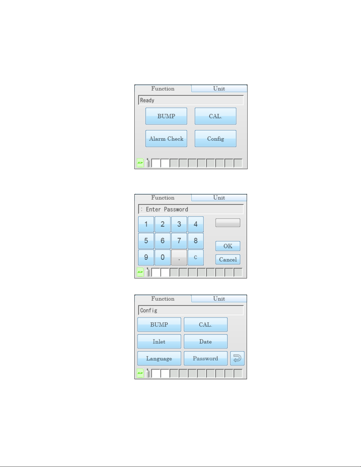
Viewing or Changing the Calibration Parameters
Do the following to set the calibration parameters.
1. Turn on the SDM-6000 system. The Function Tab will be displayed on a single station
system’s screen or on the master station’s screen in a multi-station system.
2. Press the Config button. If Password is set to on (factory setting is off), you will be
prompted for a password. Enter the password and press OK to continue.
3. The Configuration Menu will be displayed.
Chapter 3: Preparing to Use the SDM-6000 • 51
Find Quality Products Online at: sales@GlobalTestSupply.com
www.GlobalTestSupply.com
Page 52

4. Press the CAL button. 5 out of 6 calibration parameters and their current settings will be
displayed.
5. The arrow in the upper right corner takes you to the second page that shows the last of the
calibration parameters and its current setting.
6. Adjust the AIR Flush, GAS, and AIR Purge parameters as described below. The procedure
is the same for each parameter’s adjustment. AIR Flush is shown as an example.
a. Press the current value for the parameter you want to change.
b. Use the arrows to adjust the value.
c. Press OK to save the changes and return to the Bump Parameters Screen.
d. Press Cancel to return to the Calibration Parameters Screen without saving the changes.
e. Repeat step a - step d to set any other parameters.
52 • Chapter 3: Preparing to Us e the SDM-6000
Find Quality Products Online at: sales@GlobalTestSupply.com
www.GlobalTestSupply.com
Page 53

7. Select or deselect the Alarm Check, Auto Print, Manual CAL., and Auto cal if past due
parameters to turn them on or off.
8. When you are done setting the parameters, press the Return arrow button on the right side of
the screen. The Configuration Menu will be displayed.
9. To exit the Configuration Menu and return to the Function Tab’s main menu, press the
Return arrow on the right side of the screen.
Inlet Parameters
The gas inlet parameters define what gases are assigned to each port and lets you select the ports
as active or inactive.
All of the standard 4 sensors (catalytic LEL, O2, H2S, and CO) are generally assigned to GAS 1.
If the SV-3 is not being used, smart sensors (PID, ESS-03, etc.) are generally assigned to GAS 2
and GAS 3. If the SV-3 is being used, smart sensors can be assigned to GAS 2, GAS 3, GAS 4,
GAS 5, or GAS 6.
Do the following to set the gas inlet parameters.
1. Connect the GX-6000 to the SDM-6000 as described on pg.90. If you have a multi-station
system, connect GX-6000s with all of the gas combinations you plan on testing.
2. If necessary, press the Function button to display the Function Tab.
3. Press the Config button. If Password is set to on (factory setting is off), you will be
prompted for a password. Enter the password and press OK to continue.
Chapter 3: Preparing to Use the SDM-6000 • 53
Find Quality Products Online at: sales@GlobalTestSupply.com
www.GlobalTestSupply.com
Page 54

4. The Configuration Menu will be displayed.
5. Press the Inlet button.
• GAS 1 in the top left corner shows what gas inlet is currently selected for editing.
• The Actual Gas button on the left side of the screen only affects SDM-6000 operation if
the cylinder is for a PID channel. The button tells the SDM-6000 if a PID sensor’s target
gas is being used or if a surrogate gas is being used. The PID target gas is the gas
selected for the GX-6000’s PID channel from the PID Gas Name Screen in Display
Mode.
Actual Gas is selected by default and does not normally need to be deselected. The only
time that Actual Gas may need to be deselected is when you are testing a PID channel.
See pg.125 for further description.
When Actual Gas is selected for a PID cylinder, the gas inlet name on the SDM-6000’s
Unit Tab turns pink. When Actual Gas is deselected for a PID cylinder, the gas inlet
name on the SDM-6000’s Unit tab is black. Gas inlet names for all other types of sensors
(standard 4-gas, ESS-03, and IR) are always black, regardless of Actual Gas selection.
NOTE: Even though the Actual Gas selection box is selected by default, deselecting the
box will have no effect on the bump testing and calibration of the standard 4
sensors (LEL, O2, CO, H2S), ESS-03 sensors, or IR sensors.
• The Active button in the bottom left corner selects whether the gas inlet is active. This
feature is useful if you don’t want to use a particular gas inlet for a test. For example, if
54 • Chapter 3: Preparing to Us e the SDM-6000
Find Quality Products Online at: sales@GlobalTestSupply.com
www.GlobalTestSupply.com
Page 55

you have a 4-gas + low range PID GX-6000 but you only want to test the PID sensor,
you could deselect the Active button for the 4-gas inlet.
NOTE: Since the SDM-6000 only has 3 gas ports, GAS 4, GAS 5, and GAS 6 cannot be
selected as active if the SV-3 is not connected.
• Gas list in the middle of the screen shows what gas(es) are assigned to the selected inlet.
6. To change the gas(es) and/or concentration(s) for a gas inlet:
a. Press the desired gas. You can only change one gas at a time.
b. Press the arrow to the right of the gas list. The gas name, concentration, and units will be
displayed.
c. Scroll through the gas name choices using the arrows below the current selection. The
same gas cannot be assigned to an inlet twice so gases already assigned to the inlet you
are editing will not appear as a choice when scrolling through the gas options. Only
gases in currently or previously connected GX-6000(s) will appear as choices. If you
want to remove the chosen gas from the assigned inlet, scroll to the “- - -” selection. If
you are assigning multiple gases to one inlet, it does not matter what order the gases are
in.
d. Adjust the concentration using the arrows or by pressing the current setting and
manually typing in the concentration.
Chapter 3: Preparing to Use the SDM-6000 • 55
Find Quality Products Online at: sales@GlobalTestSupply.com
www.GlobalTestSupply.com
Page 56

NOTE: When setting up inlet information for the first time, concentration information
must match the auto calibration value being shown for the appropriate channel on
the Unit Tab in order to avoid an inlet error. Once the inlet information is initially
set up, that inlet information takes priority over the GX-6000’s auto calibration
values. After the initial setup, the inlet concentration does not need to match the
instrument’s auto calibration value.
e. Scroll through the unit choices using the arrows below the current selection.
f. Press OK to save the changes and return to the Inlet Parameter screen.
g. Press Cancel to return to the Inlet Parameter screen without saving any changes.
7. Use the arrows above and below the gas inlet selection to change the gas inlet. The Active
parameter’s setting and the gas list will change.
8. Repeat steps 6a - 6g for any additional gas inlets you wish to assign gas(es) to.
9. Repeat step 1 - step 8 if you only have 1 SDM-6000 but have another GX-6000 with a
different gas combination that you wish to configure the inlets for.
10. When you are finished viewing or making changes to inlet parameters, press OK to save the
changes and return to the Configuration Menu or press Cancel to return to the Configuration
Menu without saving the changes.
11. To exit the Configuration Menu and return to the Function Tab’s main menu, press the
Return arrow on the right side of the screen.
12. To turn off the GX-6000(s), press the Unit button to display and Unit Tab and then press the
Detector Off button in the lower left corner.
56 • Chapter 3: Preparing to Us e the SDM-6000
Find Quality Products Online at: sales@GlobalTestSupply.com
www.GlobalTestSupply.com
Page 57
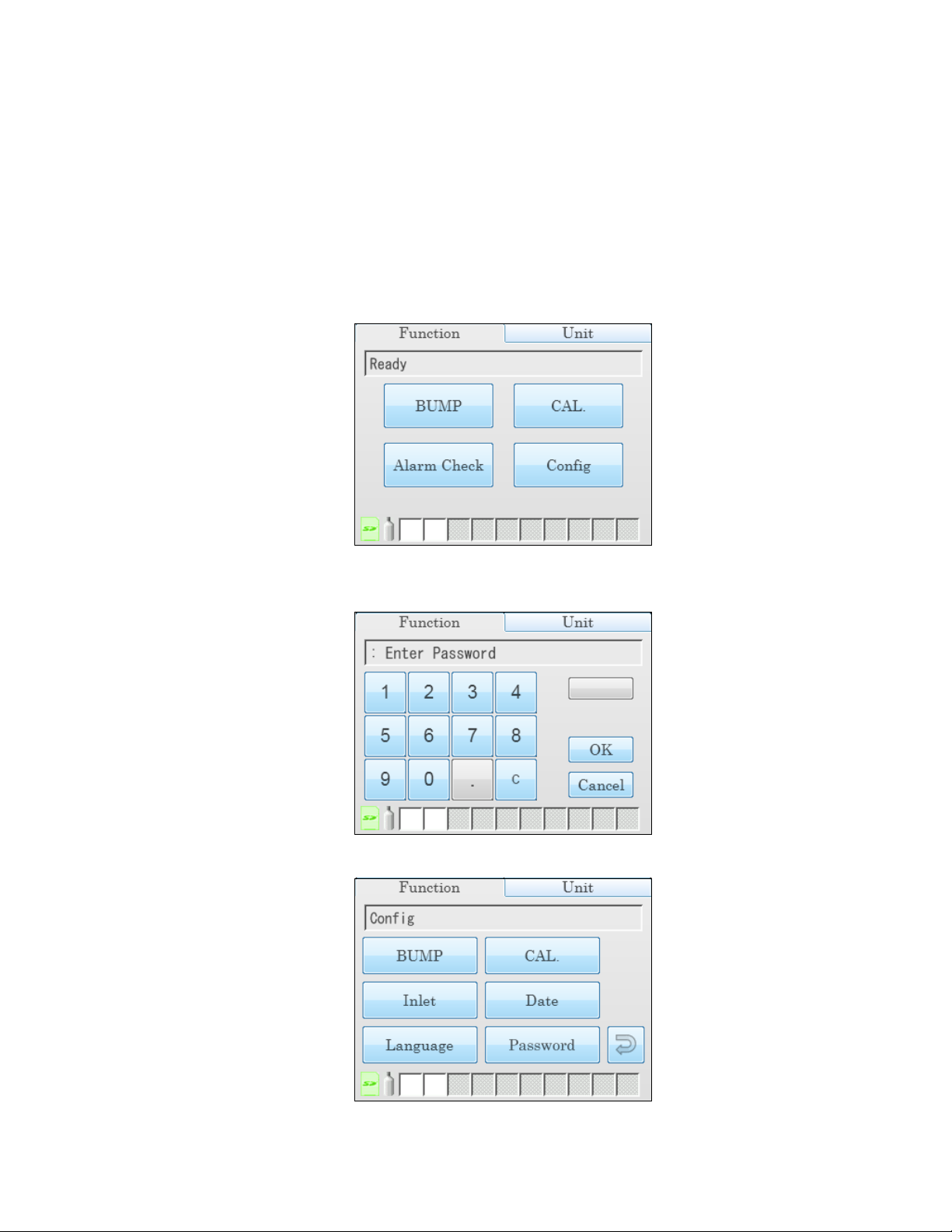
Date, Time, and Date/Time Format
It is important to update the SDM-6000’s date/time to match your time zone. The SDM-6000
automatically updates the date/time in connected GX-6000s to match the SDM-6000’s date/time.
If the date/time in your SDM-6000 is not correct and you connect your GX-6000(s), the date/time
in the GX-6000(s) will no longer be correct.
Do the following to view or change the docking station’s date, time, or date/time format.
1. Turn on the SDM-6000 system. The Function Tab will be displayed on a single station
system’s screen or on the master station’s screen in a multi-station system.
2. Press the Config button. If Password is set to on (factory setting is off), you will be
prompted for a password. Enter the password and press OK to continue.
3. The Configuration Menu will be displayed.
Chapter 3: Preparing to Use the SDM-6000 • 57
Find Quality Products Online at: sales@GlobalTestSupply.com
www.GlobalTestSupply.com
Page 58
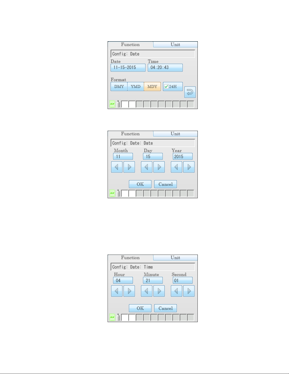
4. Press the Date button.
5. To change the date:
a. Press the Date field.
b. To change any of the month/day/year settings, use the arrows below the setting or press
the current setting and type in the desired value on the number pad that appears.
c. Press OK to save the changes and return to the Configuration Menu.
Press Cancel to return to the Configuration Menu without saving any changes.
6. To change the time:
a. Press the Time field.
58 • Chapter 3: Preparing to Us e the SDM-6000
Find Quality Products Online at: sales@GlobalTestSupply.com
www.GlobalTestSupply.com
Page 59
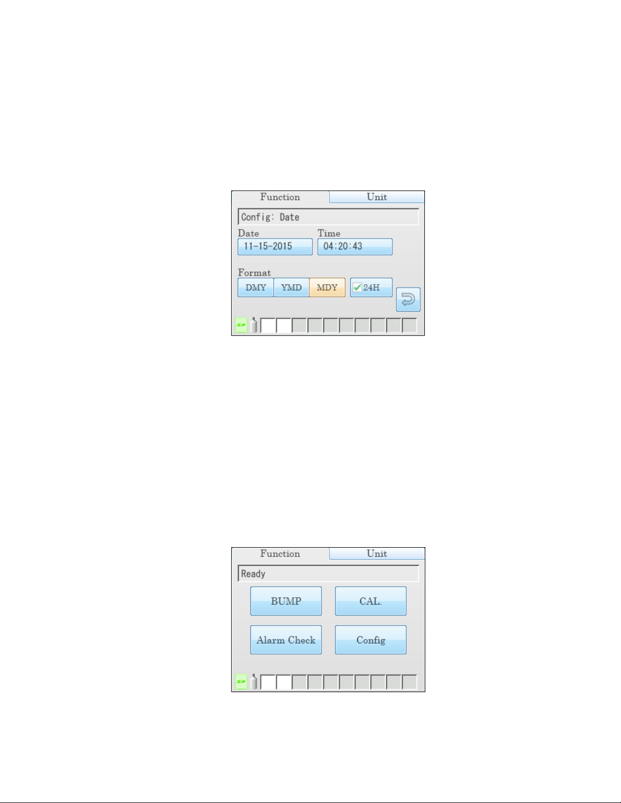
b. To change any of the settings, use the arrows below the setting or press the current
setting and type in the desired value on the number pad that appears. If the station is not
using 24-hour time, the arrows below the hour must be used to scroll through the AM
and PM times.
c. Press OK to save the changes and return to the Configuration Menu.
Press Cancel to return to the Configuration Menu without saving any changes.
7. To change the date/time format:
a. Press the desired date format.
• DMY: day, month, year
• YMD: year, month day
• MDY: month, day year
b. Select or deselect the 24H box to turn the 24 hour clock function on or off.
c. Press the Return arrow button to return to the Configuration Menu.
Language
Follow the instructions below to change the station’s language.
1. Turn on the SDM-6000 system. The Function Tab will be displayed on a single station
system’s screen or on the master station’s screen in a multi-station system.
Chapter 3: Preparing to Use the SDM-6000 • 59
Find Quality Products Online at: sales@GlobalTestSupply.com
www.GlobalTestSupply.com
Page 60

2. Press the Config button. If Password is set to on (factory setting is off), you will be
prompted for a password. Enter the password and press OK to continue.
3. The Configuration Menu will be displayed.
4. Press the Language button. The available language options will be displayed.
5. Press the desired language. There is no confirmation necessary for a language change and the
SDM-6000’s language will immediately change. The Language screen will not go away until
you press the return button so if you accidentally change the language, you can change it
back right away.
6. Press the Return arrow button to return to the Configuration Menu.
60 • Chapter 3: Preparing to Us e the SDM-6000
Find Quality Products Online at: sales@GlobalTestSupply.com
www.GlobalTestSupply.com
Page 61

Password
If Password is set to on, a password will be required to enter the Configuration Menu. If
Password is set to off (factory setting), no password is required to enter the Configuration Menu.
Do the following to turn Password on or off.
1. Turn on the SDM-6000. The Function Tab’s main menu will be displayed.
2. Press the Config button. If Password is already set to on (factory setting is off), you will be
prompted for a password. Enter the password and press OK to continue.
3. The Configuration Menu will be displayed.
Chapter 3: Preparing to Use the SDM-6000 • 61
Find Quality Products Online at: sales@GlobalTestSupply.com
www.GlobalTestSupply.com
Page 62

4. Press the Password button. The Password Menu will appear.
5. To turn the password function on or off, select or deselect the Use selection box.
6. To change the password, press Password Change.
a. You will be prompted to enter the current password. The factory set password is “0000”.
Enter the current password and press OK to proceed or Cancel to return to the Password
Menu.
b. You will be prompted to enter the new password. Enter the new password and press OK
to proceed or Cancel to return to the Password Menu.
62 • Chapter 3: Preparing to Us e the SDM-6000
Find Quality Products Online at: sales@GlobalTestSupply.com
www.GlobalTestSupply.com
Page 63
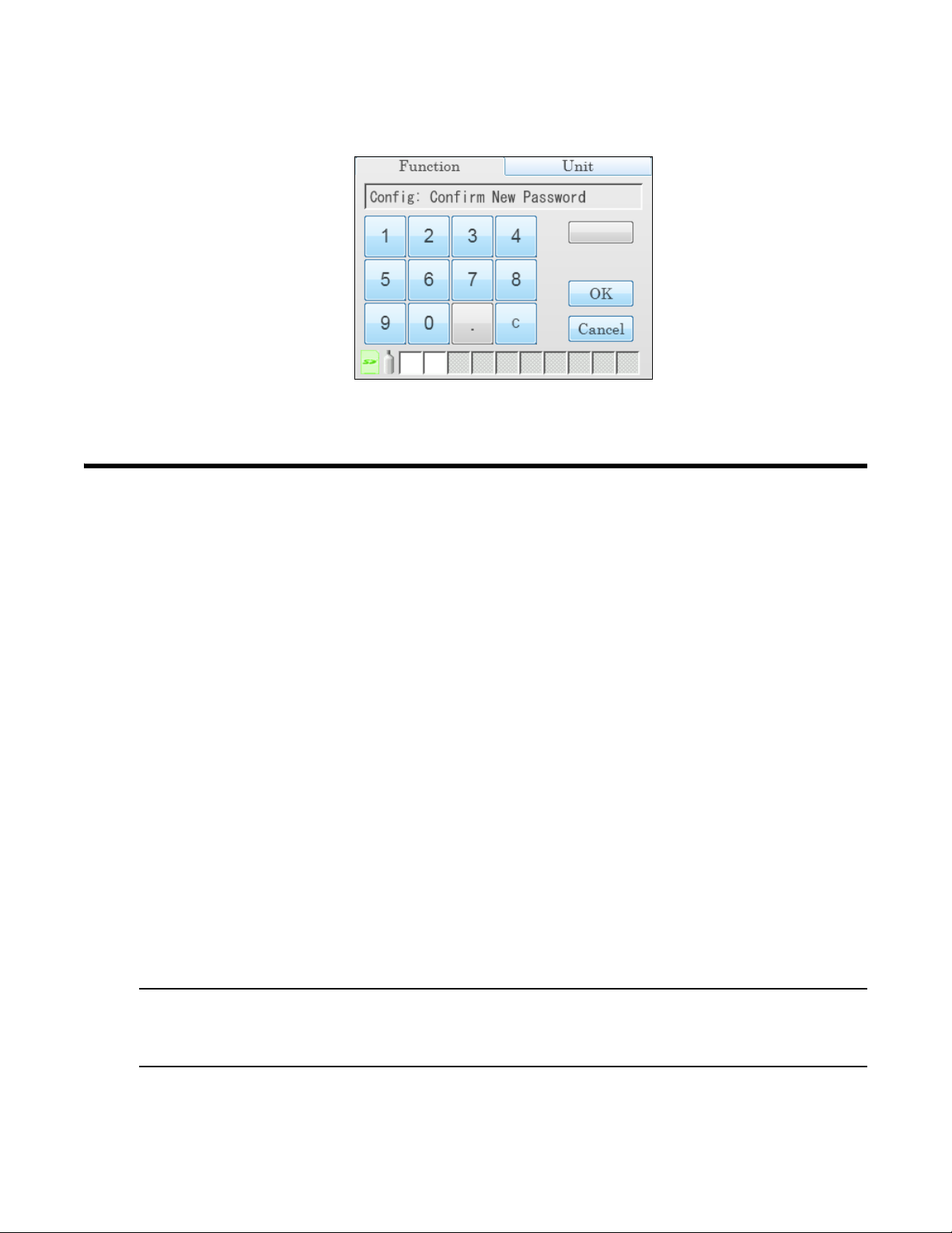
c. You will be prompted to confirm the new password. Reenter the new password and press
OK to proceed or Cancel to return to the Password Menu.
7. You will be returned to the Password Menu.
8. Press the Return arrow button to return to the Configuration Menu.
Setting Detailed Parameters Using the PC Program
The SDM-PC2 Docking Station PC Controller Program allows you to change more detailed
parameters that affect the operation of the SDM-6000 in Standalone Mode. These parameters are
not available for editing in any of the SDM-6000’s Standalone Mode menu screens. The
parameters that affect standalone operation but are only accessible using the PC Controller
program are:
• Data Logger:
• set up the SDM-6000 to automatically download the GX-6000’s logger data to the SD
card every time it’s turned on or at an interval
• enable or disable manual downloading of the GX-6000’s logger data to the SD card
• Power Saving: select how much time goes by before the GX-6000 is automatically turned
off after a successful test and after the last button push
• Expiration Date: select how many days prior to when a calibration is due that the “Cal Limit
Soon” message appears and how many days prior to a cylinder’s expiration date that the
cylinder icon turns yellow
• Automatic Execution: set up what day(s)/time the SDM-6000 will automatically bump test,
calibrate, or alarm check an installed GX-6000
• Cylinders Tab: enter cylinder information including an expiration date
See the following sections for instructions to update these parameters.
NOTE: These parameters do not need to be edited in order for the SDM-6000 to function
properly. These parameters allow you to edit features or initiate certain
operations that cannot be accessed using the SDM-6000’s Config Menu.
Chapter 3: Preparing to Use the SDM-6000 • 63
Find Quality Products Online at: sales@GlobalTestSupply.com
www.GlobalTestSupply.com
Page 64

Figure 26: Main Program Window
Launching the PC Controller Program and Connecting an SDM-6000
1. Click Start on the Windows Icon Tray, then select Programs/SDM-PC2. You may also
double click the shortcut created on your desktop. The SDM-PC2 Docking Station PC
Controller Program is launched and the main program window appears.
2. If you are starting the software for the first time, a message window appears informing you
that a database has been created. Click OK in that window.
3. Connect the AC adapter to the SDM-6000 and to an AC wall socket. If you have a multistation system, only the leftmost SDM-6000 should be connected to power.
4. Connect a Type A to Type B USB cable to the SDM-6000 and to an available USB port on
your computer. If you have a multi-station system, only the leftmost SDM-6000 should be
connected to the computer with the USB cable.
5. Flip the SDM-6000’s power switch so that it’s in the ON position. If you have a multi-station
system, only the power switch of the leftmost SDM-6000 needs to be flipped.
Accessing the SDM Configuration Window
1. Launch the PC Controller Program and connect your SDM-6000(s) as described in the
previous section.
2. Click the SDM button at the top of the screen.
64 • Chapter 3: Preparing to Us e the SDM-6000
Find Quality Products Online at: sales@GlobalTestSupply.com
www.GlobalTestSupply.com
Page 65

3. If the Password parameter in the Bump & Cal 2 Tab of the SDM Configuration Window or in
Figure 27: SDM Configuration Window
the SDM-6000’s Config Menu is set to ON, the program will prompt you for a password to
enter the SDM Configuration Window. Enter the password and click OK.
4. The SDM Configuration Window will open and the Bump & Cal 1 Tab will be displayed.
Chapter 3: Preparing to Use the SDM-6000 • 65
Find Quality Products Online at: sales@GlobalTestSupply.com
www.GlobalTestSupply.com
Page 66

Figure 28: Bump & Cal 2 Tab
Updating the Data Logger Settings
1. Launch the PC Controller Program and connect your SDM-6000(s) as described on pg.64.
2. Access the SDM Configuration Window as described on pg.64.
3. Click the Bump & Cal 2 Tab.
4. Use the drop down menu to select the desired setting for the Data Logger Auto Download
parameter.
• OFF: No data download to the SD card will be performed when a GX-6000 is connected
to the SDM-6000.
• Every Time: A data download to the SD card will automatically occur every time a GX6000 is connected to the SDM-6000.
• Interval: A data download to the SD card is performed once per interval. If this option
is selected, the Auto Download Interval parameter becomes active and needs to be set.
The Interval parameter is described below.
NOTE: A data download will take approximately 5 minutes to complete.
66 • Chapter 3: Preparing to Us e the SDM-6000
Find Quality Products Online at: sales@GlobalTestSupply.com
www.GlobalTestSupply.com
Page 67

5. If necessary, select the desired setting for the Data Logger Interval. The Data Logger
Interval is the length of time, in days, that will pass before data is automatically downloaded
from a GX-6000 if Data Logger Auto Download is set to Interval. If the GX-6000 is
connected to an SDM-6000 before the interval has passed, a data download will not
automatically occur. The Data Logger Interval can be set anywhere from 1 to 60 days. The
factory setting is 1 day. Use the arrows to the right of the current setting to change the interval
or highlight the current setting and type in the desired value.
6. Set Manual Download to the desired setting:
• When set to ON (default value), the Download button on the SDM-6000 touchscreen
becomes active and a manual download in Standalone Mode of the GX-6000’s logger
data to the SD card can be performed.
• When set to OFF, the Download button is not active and a manual download of the GX-
6000’s logger data to the SD card cannot be performed in Standalone Mode.
7. To save the changes, click SDM Update and click Ye s in the window that appears.
To return to the main window without saving any changes, click Cancel and click OK in the
window that appears.
Chapter 3: Preparing to Use the SDM-6000 • 67
Find Quality Products Online at: sales@GlobalTestSupply.com
www.GlobalTestSupply.com
Page 68

Figure 29: Bump & Cal 2 Tab
Updating the Power Saving Settings
1. Launch the PC Controller Program and connect your SDM-6000(s) as described on pg.64.
2. Access the SDM Configuration Window as described on pg.64.
3. Click the Bump & Cal 2 Tab.
4. Select the desired setting for the Power Off After Pass parameter. This is the length of time
that will pass after a successful bump test, calibration, or alarm check before the docking
station will automatically shut off the GX-6000. Use the arrows to the right of the current
setting to change the value or highlight the current setting and type in the desired value. It is
defined in seconds with a maximum setting of 99,999 seconds. The factory setting is 15
seconds. If this parameter is set to 0 seconds, the GX-6000 will not be turned off after a
successful bump test, calibration, or alarm check.
5. Select the desired setting for the Auto Power Off parameter. This is the length of time that
will pass after the last operation is finished before the docking station will automatically shut
off the GX-6000. If a successful bump test, calibration, or alarm check is performed, the
docking station will automatically shut off the GX-6000 in the time defined in Power Off
After Pass regardless of the Auto Power Off setting. Use the arrows to the right of the
current setting to change the value or highlight the current setting and type in the desired
value. It is defined in seconds with a maximum setting of 99,999 seconds. The factory setting
is 600 seconds.
68 • Chapter 3: Preparing to Us e the SDM-6000
Find Quality Products Online at: sales@GlobalTestSupply.com
www.GlobalTestSupply.com
Page 69

6. To save the changes, click SDM Update and click Ye s in the window that appears.
Figure 30: Bump & Cal 2 Tab
To return to the main window without saving any changes, click Cancel and click OK in the
window that appears.
Updating the Expiration Date Settings
1. Launch the PC Controller Program and connect your SDM-6000(s) as described on pg.64.
2. Access the SDM Configuration Window as described on pg.64.
3. Click the Bump & Cal 2 Tab.
4. Select the desired setting for the Calibration Expiration Notice parameter. This is the length
of time, in days, before a GX-6000 is due for calibration that the SDM-6000 will give an
indication that the GX-6000’s calibration due date is approaching. So if calibration is due on
12/20/15 and the Calibration Expiration Notice is set to 10 days, the impending-calibration
indication will begin appearing on 12/10/15. If the GX-6000 is connected to the SDM-6000
within this time period, “Cal Limit Soon” will display in the text field above the BUMP and
CAL buttons in the Function Tab.
5. Select the desired setting for the Cylinder Expiration Notice parameter. This is the length of
time, in days, before a cylinder’s expiration date that the SDM-6000 will give an indication
that the cylinder’s expiration date is approaching. So if the cylinder expires on 12/20/15 and
the Cylinder Expiration Notice is set to 10 days, the cylinder-expiring indication will begin
Chapter 3: Preparing to Use the SDM-6000 • 69
Find Quality Products Online at: sales@GlobalTestSupply.com
www.GlobalTestSupply.com
Page 70

Figure 31: Automatic Tab
appearing on 12/10/15. The cylinder icon in the bottom left corner of the SDM-6000’s
Function Tab will change from green to orange.
6. To save the changes, click SDM Update and click Ye s in the window that appears.
To return to the main window without saving any changes, click Cancel and click OK in the
window that appears.
Updating the Automatic Execution Settings
The Automatic Tab allows you to set up a bump test, calibration, or alarm check to automatically
occur at a specific time on the desired day(s). If a GX-6000 is installed in an SDM-6000 at the
specified day/time, the SDM-6000 will turn the GX-6000 on, perform the test, then turn the GX6000 off.
1. Launch the PC Controller Program and connect your SDM-6000(s) as described on pg.64.
2. Access the SDM Configuration Window as described on pg.64.
3. Click the Automatic Tab.
4. Use the drop down menu to select Bump Test, Alarm Check, or Calibration. Only one test
can be selected. Multiple tests cannot be done automatically.
70 • Chapter 3: Preparing to Us e the SDM-6000
Find Quality Products Online at: sales@GlobalTestSupply.com
www.GlobalTestSupply.com
Page 71

5. Highlight the hours or minutes portion of the Execute Time and then use the arrows to
Figure 32: Cylinders Window
change the selection or type in the desired value.
6. Select what day(s) you would like the test to be done in the Weekly Execution area.
7. To save the changes, click SDM Update and click Ye s in the window that appears.
To return to the main window without saving any changes, click Cancel and click OK in the
window that appears.
Updating the Cylinders Settings
This section describes how to use the Cylinders Window to update cylinder parameters and assign
cylinders to the SDM-6000 or SV-3’s gas inlets. If desired, the Cylinders Window will keep track
of those cylinders’ expiration dates. If the SDM-6000 is used in Standalone Mode, it will keep
track of the expiration dates based on the settings made in the Cylinders Window. The Cylinders
Window comes with a list of predefined cylinders that are fairly common. If a cylinder that you
need to use is not on this list, you can define your own cylinder. Some of the parameters available
for editing in the Cylinders Window, such as gas name and concentration, do not need to be set
using the PC Controller Program and can be set using the SDM-6000’s Config Menu. In order to
provide more comprehensive instructions, this section will include instructions for setting
parameters that can also be set using the SDM-6000’s Config Menu.
The Cylinders Window shows the cylinder name, cylinder part number, expiration date, active
status, and actual gas selection status for each cylinder.
Selecting a Cylinder from the Predefined List
The Cylinders Window comes with several predefined cylinders that you can choose from.
Setting up a cylinder in the Cylinders Window is the same as setting the inlet parameters at the
SDM-6000 using the Config Menu.
1. Launch the PC Controller Program and connect your SDM-6000(s) as described on pg.64.
Chapter 3: Preparing to Use the SDM-6000 • 71
Find Quality Products Online at: sales@GlobalTestSupply.com
www.GlobalTestSupply.com
Page 72

2. Click the Cylinders button along the top of the main program window.
Figure 33: Cylinders Window
Figure 34: Cylinder Detail Window
3. The Cylinders Window will appear.
4. Double click the line (or single click the line and click Edit) that corresponds with the gas
inlet you’d like to set up. For example, double click line 1 (or single click line 1 and click
Edit) to set up a cylinder for the GAS 1 inlet on the SDM-6000 or SV-3. The Cylinder Detail
window will display.
72 • Chapter 3: Preparing to Us e the SDM-6000
Find Quality Products Online at: sales@GlobalTestSupply.com
www.GlobalTestSupply.com
Page 73
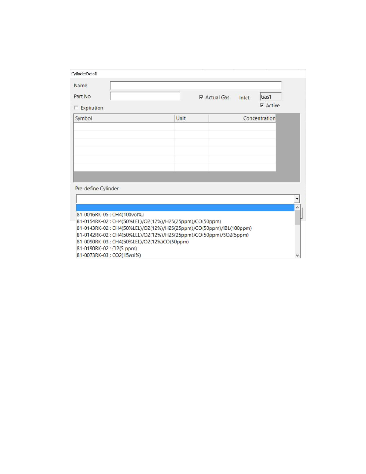
5. The pre-defined cylinders list is located in a drop down menu at the bottom of the window.
Figure 35: Pre-Defined Cylinders List
Click the drop down arrow to view the pre-defined cylinders list. Scroll down to view
additional cylinders.
Chapter 3: Preparing to Use the SDM-6000 • 73
Find Quality Products Online at: sales@GlobalTestSupply.com
www.GlobalTestSupply.com
Page 74
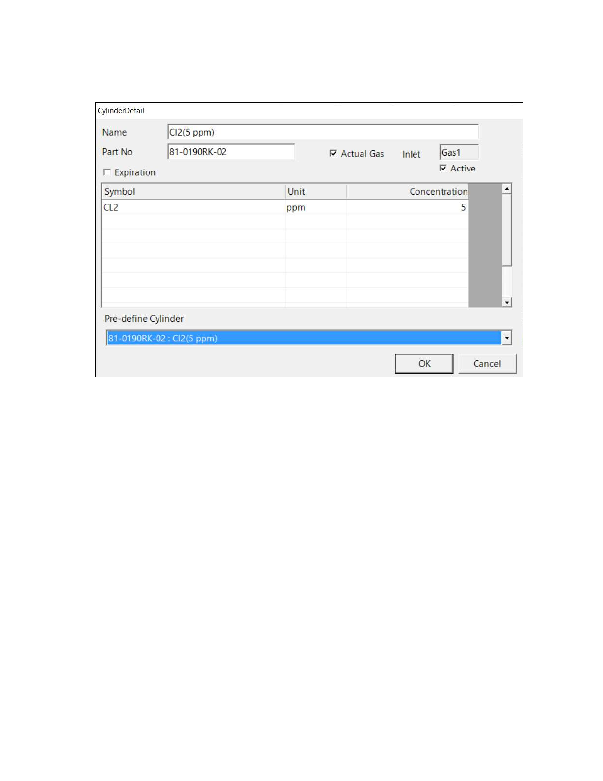
Figure 36: Cylinder Detail Window Filled In with Pre-Defined Info
6. Click the cylinder you’d like to use. In this example, Cl2 has been selected. The Name, Part
No., Symbol, Unit, and Concentration fields will automatically be filled in.
74 • Chapter 3: Preparing to Us e the SDM-6000
Find Quality Products Online at: sales@GlobalTestSupply.com
www.GlobalTestSupply.com
Page 75
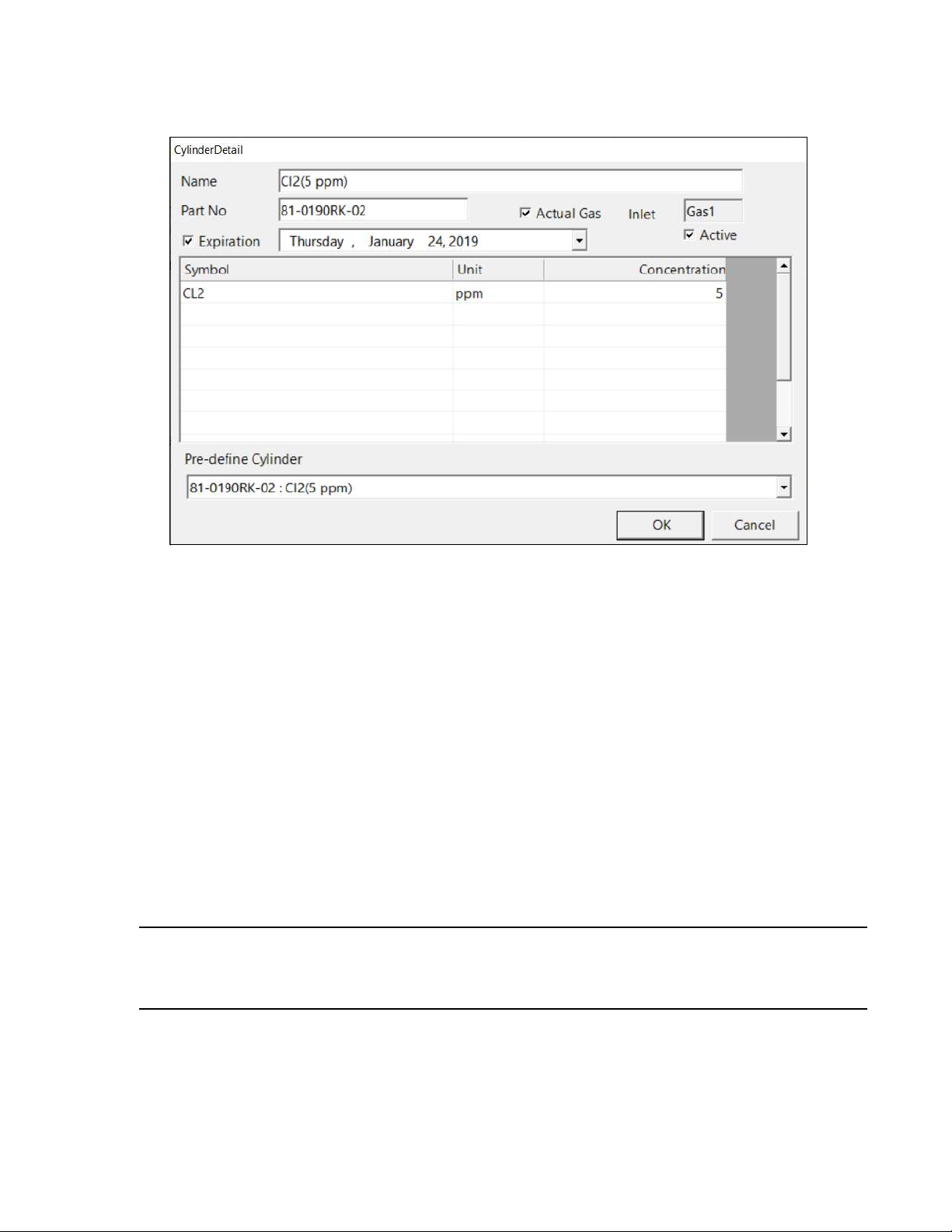
7. If you would like to set an expiration date for the cylinder, select the box next to Expiration.
Figure 37: Expiration Date
8. Set the expiration date by clicking the drop down menu arrow and selecting a date from the
calendar that appears. If the number of days left before the cylinder expires is less than the
time defined in the Cylinder Expiration Notice parameter in the SDM Configuration
Window, the line in the Cylinders Window that corresponds to this cylinder will turn orange.
The line in the Cylinders Window that corresponds to this cylinder will turn red if the
expiration date has passed.
9. Select or deselect the Actual Gas box for the cylinder. The Actual Gas box only affects
SDM-6000 operation if the cylinder is for a PID channel. The button tells the SDM-6000 if a
PID sensor’s target gas is being used or if a surrogate gas is being used. The PID target gas is
the gas selected for the GX-6000’s PID channel from the PID Gas Name Screen in Display
Mode.
Actual Gas is selected by default and does not normally need to be deselected. The only time
that Actual Gas may need to be deselected is when you are testing a PID channel. See pg.125
for further description.
NOTE: Even though the Actual Gas selection box is selected by default, deselecting the
box will have no effect on the bump testing and calibration of the standard 4
sensors (LEL, O2, CO, H2S), ESS-03 sensors, or IR sensors.
Chapter 3: Preparing to Use the SDM-6000 • 75
Find Quality Products Online at: sales@GlobalTestSupply.com
www.GlobalTestSupply.com
Page 76

10. Select or deselect the Active box for the cylinder. If the cylinder is active, the PC Controller
Program will alert you at start up if the cylinder has passed its expiration date and will
include the associated inlet in testing. If it is not active, the program will not alert you if the
cylinder has passed its expiration date and will not include the associated inlet in testing.
If the Active box is deselected, the program will not consider it a cylinder being used and will
give you an inlet error if you connect an instrument that requires that cylinder for bump
testing or calibration.
11. To return to the Cylinders Window and save your changes, click OK in the Cylinder Detail
Window.
To return to the Cylinders Window without saving your changes, click Cancel.
12. Make any necessary updates to other inlets.
13. To return to the Main Window and save your changes, click OK in the Cylinders Window
and then click Ye s in the window that comes up.
To return to the Main Window without saving your changes, click Cancel in the Cylinders
Window and then click OK in the window that comes up.
Defining New Cylinders
If your GX-6000 configuration requires the use of a cylinder that is not in the predefined list, you
can add that cylinder by either typing in the information for the cylinder or by editing the
information for an existing cylinder.
Defining a cylinder in the Cylinders Window is the same as setting the inlet parameters at the
SDM-6000 using the Config Menu.
1. Launch the PC Controller Program and connect your SDM-6000(s) as described on pg.64.
2. Click the Cylinders button along the top of the main program window.
76 • Chapter 3: Preparing to Us e the SDM-6000
Find Quality Products Online at: sales@GlobalTestSupply.com
www.GlobalTestSupply.com
Page 77
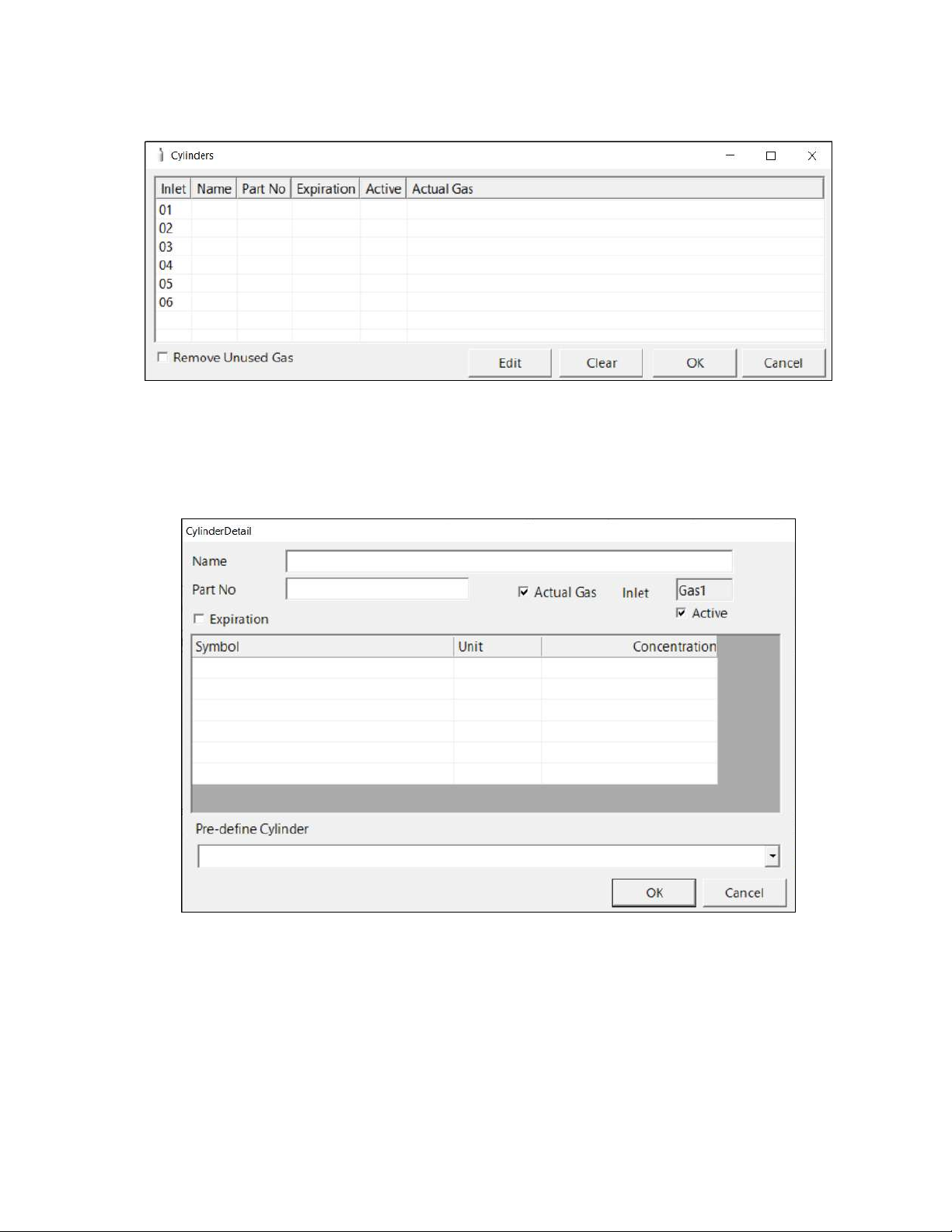
3. The Cylinders Window will appear.
Figure 38: Cylinders Window
Figure 39: Cylinder Detail Window
4. Double click the line (or single click the line and click Edit) that corresponds with the gas
inlet you’d like to set up. For example, double click line 1 (or single click line 1 and click
Edit) to set up a cylinder for the GAS 1 inlet on the SDM-6000 or SV-3. The Cylinder Detail
window will display.
5. Click in the Name field and type in a name for the cylinder. Use something descriptive that
will help you distinguish it from other cylinders. You can also select a pre-defined cylinder
and then edit the name that is automatically generated.
6. If you want to enter a part number for the cylinder, click in the Part No field and type in a
part number. This field is normally used for an RKI part number.
Chapter 3: Preparing to Use the SDM-6000 • 77
Find Quality Products Online at: sales@GlobalTestSupply.com
www.GlobalTestSupply.com
Page 78
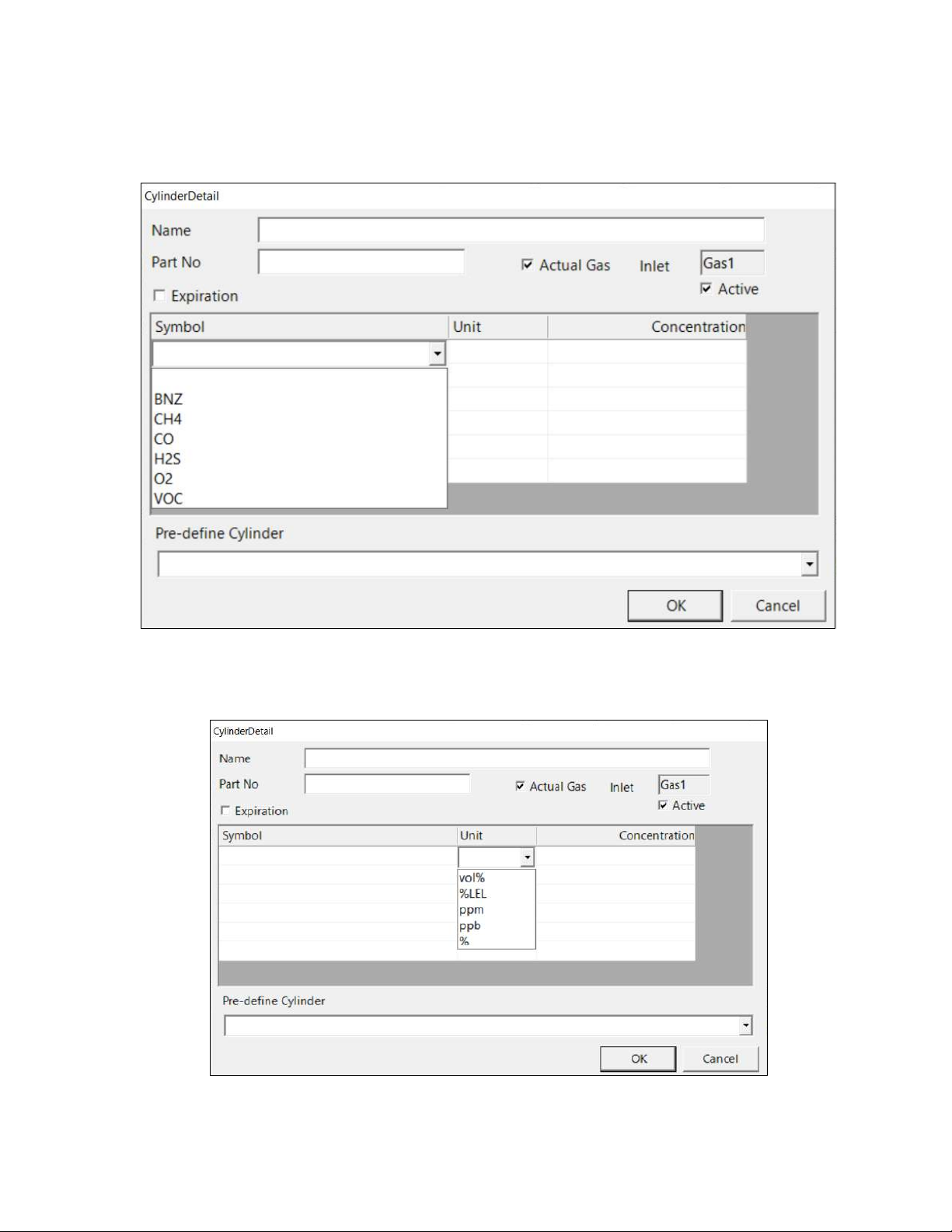
Figure 40: Symbol List
Figure 41: Unit List
7. Enter a gas symbol for each cylinder component you want to identify. Click in the Symbol
field of the desired line and type in characters or click the drop down arrow and select a
symbol from the list.
8. Enter the units for cylinder component by clicking in the Unit field, clicking the drop down
arrow, and selecting units from the list.
78 • Chapter 3: Preparing to Us e the SDM-6000
Find Quality Products Online at: sales@GlobalTestSupply.com
www.GlobalTestSupply.com
Page 79

9. Enter the gas concentration for each cylinder component by clicking in the Concentration
field and typing in the characters.
10. Set the expiration date by clicking the drop down menu arrow and selecting a date from the
calendar that appears. If the number of days left before the cylinder expires is less than the
time defined in the Cylinder Expiration Notice parameter in the SDM Configuration
Window, the line in the Cylinders Window that corresponds to this cylinder will turn orange.
The line in the Cylinders Window that corresponds to this cylinder will turn red if the
expiration date has passed.
11. Select or deselect the Actual Gas box for the cylinder. The Actual Gas box only affects
SDM-6000 operation if the cylinder is for a PID channel. The button tells the SDM-6000 if a
PID sensor’s target gas is being used or if a surrogate gas is being used. The PID target gas is
the gas selected for the GX-6000’s PID channel from the PID Gas Name Screen in Display
Mode.
Actual Gas is selected by default and does not normally need to be deselected. The only time
that Actual Gas may need to be deselected is when you are testing a PID channel. See pg.125
for further description.
NOTE: Even though the Actual Gas selection box is selected by default, deselecting the
box will have no effect on the bump testing and calibration of the standard 4
sensors (LEL, O2, CO, H2S), ESS-03 sensors, or IR sensors.
12. Select or deselect the Active box for the cylinder. If the cylinder is active, the PC Controller
Program will alert you at start up if the cylinder has passed its expiration date and will
include the associated inlet in testing. If it is not active, the program will not alert you if the
cylinder has passed its expiration date and will not include the associated inlet in testing.
If the Active box is deselected, the program will not consider it a cylinder being used and will
give you an inlet error if you connect an instrument that requires that cylinder for bump
testing or calibration.
13. To return to the Cylinders Window and save your changes, click OK in the Cylinder Detail
Window.
To return to the Cylinders Window without saving your changes, click Cancel.
14. Make any necessary updates to other inlets.
15. To return to the Main Window and save your changes, click OK from the Cylinders Window
and then click Ye s in the window that comes up.
To return to the Main Window without saving your changes, click Cancel from the Cylinders
Window and then click OK in the window that comes up.
Chapter 3: Preparing to Use the SDM-6000 • 79
Find Quality Products Online at: sales@GlobalTestSupply.com
www.GlobalTestSupply.com
Page 80

Figure 42: Cylinders Window
Figure 43: Cylinder Selected
Clearing Cylinders
Cylinders can be cleared from the Cylinders Window list if they are no longer needed or if you
want to clear the old cylinder before defining a new cylinder.
1. Launch the PC Controller Program and connect your SDM-6000(s) as described on pg.64.
2. Click the Cylinders button along the top of the main program window.
3. The Cylinders Window will appear.
4. Single click the line you want to clear.
5. Click the Clear button at the bottom of the screen.
6. Click OK in the window that comes up to clear the cylinder. The cylinder will disappear from
the Cylinders Window.
80 • Chapter 3: Preparing to Us e the SDM-6000
Find Quality Products Online at: sales@GlobalTestSupply.com
www.GlobalTestSupply.com
Page 81

Removing Unused Gases
As you enter cylinder information for the inlets, the Symbol drop down menu in the Cylinder
Detail Window will populate with those gas names. If you then clear the cylinders from the
Cylinders Window, those gas names will still remain in the Symbol drop down menu. Selecting
Remove Unused Gas in the Cylinders Window and then clicking OK removes those unused gas
names from the Symbol drop down menu.
1. Make the desired changes to the Cylinders Window as described in the previous 3 sections.
2. Select the Remove Unused Gas box in the bottom left corner of the screen.
3. Click OK and then click Ye s in the window that appears.
Setting Up LAN Connectivity
Connecting the SDM-6000 to a LAN network allows you to download data from the SDM-6000’s
SD card to the PC Controller Program using a computer connected to the same LAN network.
This can be convenient if your SDM-6000s are spread out throughout the building or if you do not
want to remove the SD card from the SDM-6000 in order to download the data. This section
describes how to connect your SDM-6000(s) to a network port and set up the LAN connectivity.
“Chapter 6: Importing Data Into the SDM-PC2 PC Program” on page 115 describes how to
import data once the LAN connectivity is set up.
NOTE: For users with a DHCP network, keep in mind that if the LAN connectivity was
set up but the SDM-6000 lost power or the network went down for a period of
time, you may need to set up the LAN connectivity again. A new IP address may
have been assigned to the SDM-6000 when power was restored or when the
network came back up.
1. If you have a DHCP network:
NOTE: For users with a DHCP network, keep in mind that if the LAN connectivity was
set up but the SDM-6000 lost power or the network went down for a period of
time, you may need to set up the LAN connectivity again. A new IP address may
have been assigned to the SDM-6000 when power was restored or when the
network came back up.
a. Click Start on the Windows Icon Tray, then select Programs/SDM-PC2. You may also
double click the shortcut created on your desktop. The SDM-PC2 Docking Station PC
Controller Program is launched and the main program window appears.
b. If you are starting the software for the first time, a message window appears informing
you that a database has been created. Click OK in that window.
Chapter 3: Preparing to Use the SDM-6000 • 81
Find Quality Products Online at: sales@GlobalTestSupply.com
www.GlobalTestSupply.com
Page 82
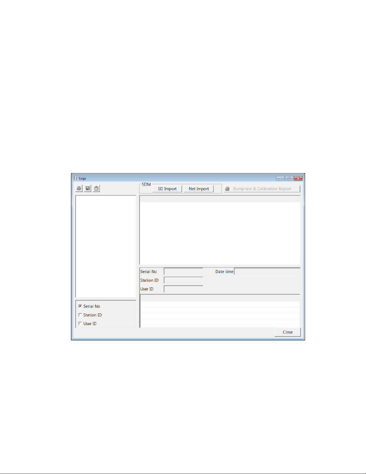
Figure 44: Logs Window
c. Connect the SDM-6000 to the network port closest to its installed location using the
SDM-6000’s LAN port and an Ethernet cable. If you have multiple SDM-6000s
connected together, only the leftmost SDM-6000 needs to be connected to a network
port. Be sure to connect all SDM-6000s or SDM-6000 banks you plan on having
connected to the LAN network. There is no need to connect 1 at a time to perform the
setup. Be sure the SDM-6000s are in their intended installation locations. They do not
need to be close to the PC being used for setup.
d. Connect the AC adapter to the SDM-6000 and to an AC wall socket. If you have
multiple SDM-6000s connected together, only the leftmost SDM-6000 should be
connected to power.
e. Flip the SDM-6000’s power switch so that it’s in the ON position. If you have multiple
SDM-6000s connected together, only the power switch of the leftmost SDM-6000 needs
to be flipped.
f. Click the Logs button in the PC Controller Program.
82 • Chapter 3: Preparing to Us e the SDM-6000
Find Quality Products Online at: sales@GlobalTestSupply.com
www.GlobalTestSupply.com
Page 83

g. Click Net Import.
Figure 45: Net Import Window
h. Click Search. The program will find any SDM-6000s that are connected to the same
network as the PC you are using.
Chapter 3: Preparing to Use the SDM-6000 • 83
Find Quality Products Online at: sales@GlobalTestSupply.com
www.GlobalTestSupply.com
Page 84

Figure 46: Net Import Window with Found SDM-6000s
Figure 47: Edit Window
i. Once the program has completed the search, the found SDM-6000(s) will appear in the
Net Import Screen with their serial number(s) and assigned IP address(es).
j. If you would like to rename an SDM-6000 to describe its location or some other defining
parameter in more detail, click on the desired SDM-6000 and then click Edit. Type in the
desired name for the SDM-6000. DO NOT CHANGE THE IP ADDRESS FIELD.
k. Continue to step 3.
84 • Chapter 3: Preparing to Us e the SDM-6000
Find Quality Products Online at: sales@GlobalTestSupply.com
www.GlobalTestSupply.com
Page 85

2. If you do not have a DHCP network:
NOTE: The LAN connectivity must be set up 1 SDM-6000 (or master SDM-6000 if you
have a bank) at a time. You cannot have multiple SDM-6000s connected to your
PC while performing the LAN connectivity setup procedure.
a. Click Start on the Windows Icon Tray, then select Programs/SDM-PC2. You may also
double click the shortcut created on your desktop. The SDM-PC2 Docking Station PC
Controller Program is launched and the main program window appears.
b. If you are starting the software for the first time, a message window appears informing
you that a database has been created. Click OK in that window.
c. Connect the SDM-6000 to a PC using the SDM-6000’s PC port and a Type A to Type B
USB cable. The SDM-6000 does not need to be installed in its intended location or
connected to the network in order to set up the LAN connectivity. It just needs to be
connected to the PC Controller Program. If you have multiple SDM-6000s connected
together, only the leftmost SDM-6000 needs to be connected to the PC.
d. Connect the AC adapter to the SDM-6000 and to an AC wall socket. If you have
multiple SDM-6000s connected together, only the leftmost SDM-6000 should be
connected to power.
e. Flip the SDM-6000’s power switch so that it’s in the ON position. If you have multiple
SDM-6000s connected together, only the power switch of the leftmost SDM-6000 needs
to be flipped.
f. Click the SDM button.
Chapter 3: Preparing to Use the SDM-6000 • 85
Find Quality Products Online at: sales@GlobalTestSupply.com
www.GlobalTestSupply.com
Page 86

g. Click the Internal tab.
Figure 48: Internal Tab
h. Be sure DHCP is deselected.
i. Enter an IP Address, SubNet Mask, and Default Gateway for the SDM-6000.
j. Click SDM Update and click Ye s in the window that comes up.
k. Turn the SDM-6000 off and then on again before continuing.
86 • Chapter 3: Preparing to Us e the SDM-6000
Find Quality Products Online at: sales@GlobalTestSupply.com
www.GlobalTestSupply.com
Page 87

l. Click the Logs button.
Figure 49: Logs Window
Figure 50: Net Import Window
m. Click Net Import.
Chapter 3: Preparing to Use the SDM-6000 • 87
Find Quality Products Online at: sales@GlobalTestSupply.com
www.GlobalTestSupply.com
Page 88

Figure 51: Add Window
Figure 52: Net Import Window with Manually Added SDM-6000
n. Click Add.
o. Enter a name for the SDM-6000 and enter the IP Address that you assigned to the SDM-
6000 in the Internal Tab of the SDM Configuration Window.
p. Click OK. The newly added SDM-6000 will appear.
q. Disconnect the USB cable from the SDM-6000, turn off the SDM-6000, and unplug the
AC adapter from the wall.
r. Move the SDM-6000 to its intended installation location and plug the AC adapter into
the wall and turn on the SDM-6000.
s. Connect the SDM-6000 to a network port using the SDM-6000’s LAN port and an
ethernet cable. If you have multiple SDM-6000s connected together at the SDM-6000
location, only the leftmost SDM-6000 needs to be connected to a network port.
t. Repeat c- sfor any additional SDM-6000s.
88 • Chapter 3: Preparing to Us e the SDM-6000
Find Quality Products Online at: sales@GlobalTestSupply.com
www.GlobalTestSupply.com
Page 89

u. Continue to step 3.
3. Click Close in the Net Import Window.
4. Exit the SDM-PC2 program by clicking the Exit button.
Chapter 3: Preparing to Use the SDM-6000 • 89
Find Quality Products Online at: sales@GlobalTestSupply.com
www.GlobalTestSupply.com
Page 90

Chapter 4: Operation
Overview
When you have completed the tasks in "Chapter 3: Preparing to Use the SDM-6000", you are
ready to use the SDM-6000 docking station. The SDM-6000 is capable of performing bump tests,
calibrations, and alarm checks on the GX-6000. It can also charge the rechargeable Li-ion battery
pack in the GX-6000. This chapter describes procedures for using the docking station to bump
test, calibrate, alarm check, download instrument logger data to the SD card, and recharge GX6000s in the standalone configuration of the docking station. It also describes the information that
is saved to an inserted SD card.
NOTE: When the GX-6000 is connected to the SDM-6000, the GX-6000’s date and time
are automatically updated to the SDM-6000’s current date and time. Ensure that
the SDM-6000’s date and time are correct before connecting a GX-6000.
Automatically Initiated Tests and Data Download
If the PC Controller Program has been used to set up the auto bump, auto cal, or auto alarm check
feature, the GX-6000 will be turned on at the set time on the set day(s) and perform the desired
test.
If the PC Controller Program has been used to set up the auto download feature, the GX-6000 will
download its data to the SD card at power up when a download is due.
NOTE: A data download will take approximately 5 minutes to complete.
Each test or download progresses as described in the appropriate section below, but no user
involvement is required to start the test or download. For an automatic calibration or test, even
after the GX-6000 is turned off, the test results will remain displayed in the Unit Tab until the user
presses the BUMP End, CAL End, or Alarm Check End button (whichever is appropriate) in
the Function Tab.
Turning on an SDM-6000 System
Do the following to turn on the SDM-6000 and establish a connection with a GX-6000:
1. Connect the AC adapter to the SDM-6000 and to an AC wall socket. If you have a multistation system, only the leftmost SDM-6000 should be connected to power.
2. Flip the SDM-6000’s power switch so that it’s in the ON position. If you have a multi-station
system, only the power switch of the leftmost SDM-6000 needs to be flipped.
3. The SDM-6000’s Status LED will be solid green if it is operating properly or solid red if
there is a system failure.
90 • Chapter 4: Operation
Find Quality Products Online at: sales@GlobalTestSupply.com
www.GlobalTestSupply.com
Page 91

4. In a single station system, the Function Tab will be on the screen when the SDM-6000 is
Figure 53: Single Station Screen at Power Up, No Connected Instruments
Figure 54: Multi-Station Screens at Power Up, No Connected Instruments
Function Tab, Master Station Slave Station(s)
powered up.:
In a multi-station system, the Function Tab will be on the screen on the master station and the
slave stations’ screens will indicate the information normally shown on the Unit Tab.
5. The Station/Instrument Indicator(s) along the bottom of a single station system’s or master
station’s Function Tab corresponding to each connected SDM-6000 will be will be white. For
a single station system, only the leftmost indicator will be white. Any indicators that are light
gray mean that there is not an SDM-6000 connected to the system in that position. The
indicators in the Master Station Function Tab above show that two SDM-6000s are connected
in this system.
6. The SD card logo in the bottom left corner of the Function Tab will indicate if an SD card is
installed and, if installed, the amount of memory that is available (see pg.111). Be sure that an
SD card is installed so that test data and GX-6000 data logger data from automatically or
manually initiated operations are saved. If you have a multi-station system, the SD card only
needs to be inserted into the master (leftmost) station’s SD card slot.
Chapter 4: Operation • 91
Find Quality Products Online at: sales@GlobalTestSupply.com
www.GlobalTestSupply.com
Page 92

Figure 55: Inserting the GX-6000
DC24V
ON
OFF
PRINTERPRINTER
LAN
PC
7. Install a GX-6000 in the instrument cradle. Orient the GX-6000 so the belt clip is facing
away from the SDM-6000. Set the bottom of the GX-6000 in the bottom of the instrument
cradle and push the top of the GX-6000 toward the SDM-6000. When the front face of the
GX-6000 touches the back of the cradle, push the GX-6000 gently towards the back of the
cradle to snap it in place.
8. If the GX-6000 is equipped with a Li-ion battery pack that needs to be charged, the Status
LED will begin to flash orange. If the battery pack is fully charged, the Status LED will be
solid orange. See pg.108 for a complete description of charging the GX-6000.
9. Push the red gas in/gas out cover down until it touches the GX-6000 and then release it. It
should lock into place against the top of the GX-6000. If it returns to its original position,
attempt to lock it in place again.
10. The GX-6000 will turn on once the gas in/gas out cover is in place. Any instrument charging
that was taking place will stop and the SDM-6000 Status LED will blink green.
11. Repeat step 7 - step 10 for any additional SDM-6000s and GX-6000s.
92 • Chapter 4: Operation
Find Quality Products Online at: sales@GlobalTestSupply.com
www.GlobalTestSupply.com
Page 93
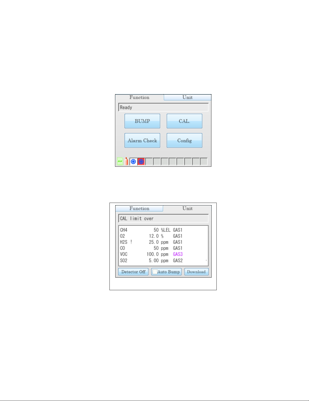
12. The GX-6000 will begin its power up sequence. The status of the instrument is shown by the
Single Station Unit Tab
Station/Instrument Indicators at the bottom of the Function Tab. The color of the
corresponding indicator and the logo shown in it will indicate the status of the instrument.
For example, the master station screen below indicates that the instrument in position 1 is
connected to the SDM-6000 and the Active box in the Unit Tab is selected. It also indicates
that the instrument in position 2 is connected to the SDM-6000, the Active box in the Unit
Tab is selected, and the GX-6000 is due for calibration. See pg.12 for a complete description
of the indicators’ colors and logos.
13. If a successful connection between the GX-6000 and the SDM-6000 occurs, the Unit Tab
screen will indicate the instrument’s active channels and the calibration gas concentration
values for each channel. If you have a single station system, press the Unit Tab at the top of
the screen to bring it to view it. See pg.15 for a description of the Unit Tab.
Chapter 4: Operation • 93
Find Quality Products Online at: sales@GlobalTestSupply.com
www.GlobalTestSupply.com
Page 94
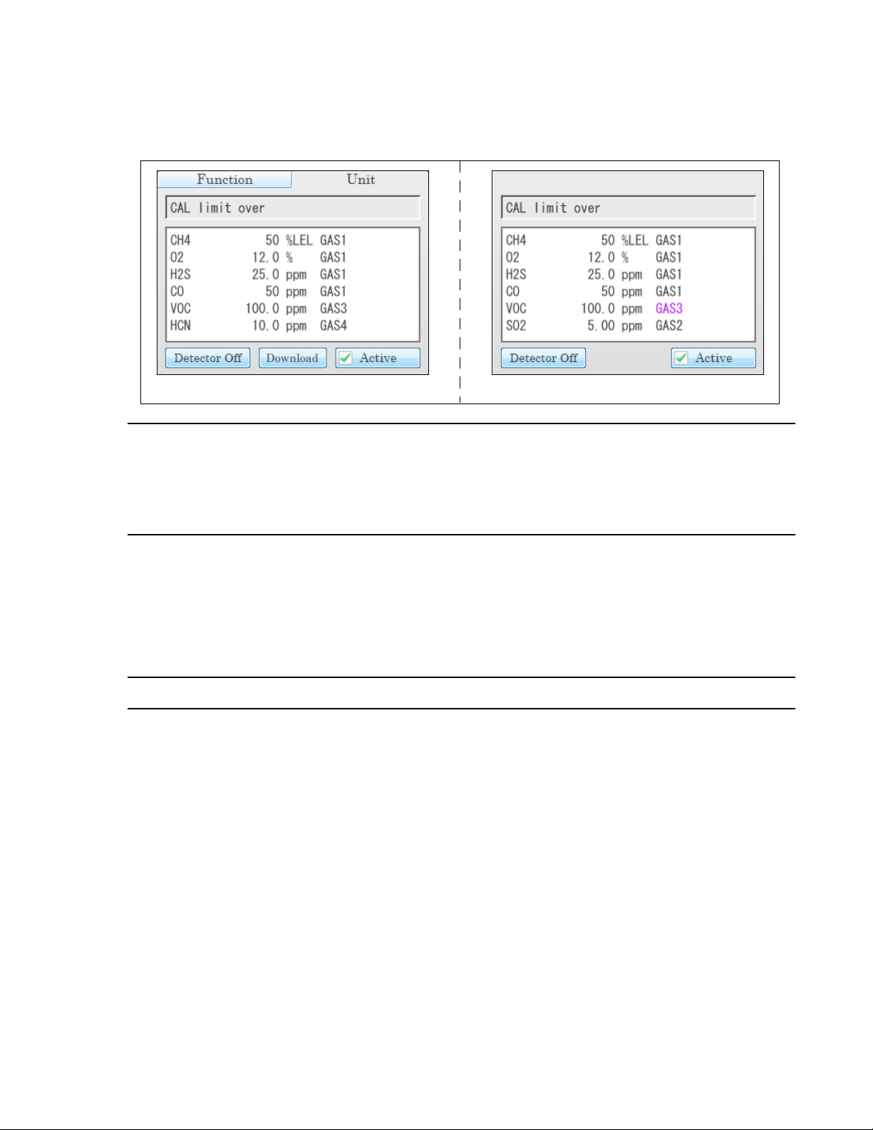
Master Station Unit Tab Slave Station
If you have a multi-station system, press the Unit Tab at the top of the master station’s screen
to view it. The slave SDM-6000(s) stations’ screens will indicate the information normally
shown on the Unit Tab.
NOTE: The single station screen shown above shows a 4-gas + SO2 GX-6000 installed
in the SDM-6000. The multi-station screens shown above shows a 4-gas + high
range PID + HCN GX-6000 installed in the master SDM-6000 and a 4-gas +
NO2 GX-6000 installed in the slave SDM-6000. If you have different
instruments, your screens will appear differently.
14. When the GX-6000 is connected to the SDM-6000, the GX-6000’s date and time are
automatically updated to the SDM-6000’s current date and time.
15. If you used the PC Controller Program to set up an automatic data download and if a
download is due, the download will begin as soon as the GX-6000 is connected to the SDM-
6000.
NOTE: A data download will take approximately 5 minutes to complete.
16. If you are using a single station system and the Auto Bump selection box is selected on the
Function Tab, a bump test will begin either as soon as the GX-6000 is connected to the SDM6000 or after instrument data is downloaded if you used the PC controller Program to set up
an automatic data download and if a download is due.
94 • Chapter 4: Operation
Find Quality Products Online at: sales@GlobalTestSupply.com
www.GlobalTestSupply.com
Page 95

Bump Testing
When a bump test is performed, the SDM-6000 performs a fresh air adjustment on a GX-6000
and then applies calibration gas to the instrument. The docking station then analyzes the response
results based on criteria defined by the bump test check tolerance parameter and determines if the
instrument passed the bump test. The bump test check tolerance is defined on pg.45. If the
automatic calibration parameter is set to on, then the SDM-6000 will automatically perform a
calibration if the bump test fails.
Be sure that you have the required calibration cylinders for your sensors. If you are using a 5-gas
cylinder for a special sensor, be sure that the gas inlet parameters are appropriately assigned as
described in “Inlet Parameters” on page 53.
NOTE: If you wish to bump test only the standard four sensors or only the smart sensors,
NOTE: The GX-6000’s BUMP DISP parameter must be set to ON to have the GX-
be sure that the Gas Inlet Parameters are set appropriately as described on pg.53.
6000’s bump test date reset after a successful bump test in an SDM-6000.
Do the following to perform a bump test:
1. Turn on the SDM-6000 system as described on pg.90.
2. Confirm that you have an SD card installed in the system.
NOTE: If an SD card is not installed, then test data and instrument data logger data
downloaded manually or automatically cannot be saved.
3. If necessary, confirm that the bump test parameters are set to the desired values. See pg.44.
4. If a connected GX-6000’s channels does not have an assigned gas inlet or if the gas inlet
setup is not correct, a gas inlet error will occur. A bump test can still be initiated but the
incorrectly set up channel will not be bump tested.
5. If you have a multi-station system and a slave station is turned on but you do not want it to be
included in the testing, deselect the Active box in the lower right corner of the Unit Tab.
6. Verify that the appropriate calibration gas cylinders are connected to the gas fittings on the
left side of the SDM-6000 or to the gas fittings on the SV-3. See pg.38 and pg.41 for
calibration gas cylinder options and calibration gas connection procedures.
7. If you are bump testing a Cl2 sensor, verify that all best practices outlined on pg.27 are being
followed.
Chapter 4: Operation • 95
Find Quality Products Online at: sales@GlobalTestSupply.com
www.GlobalTestSupply.com
Page 96
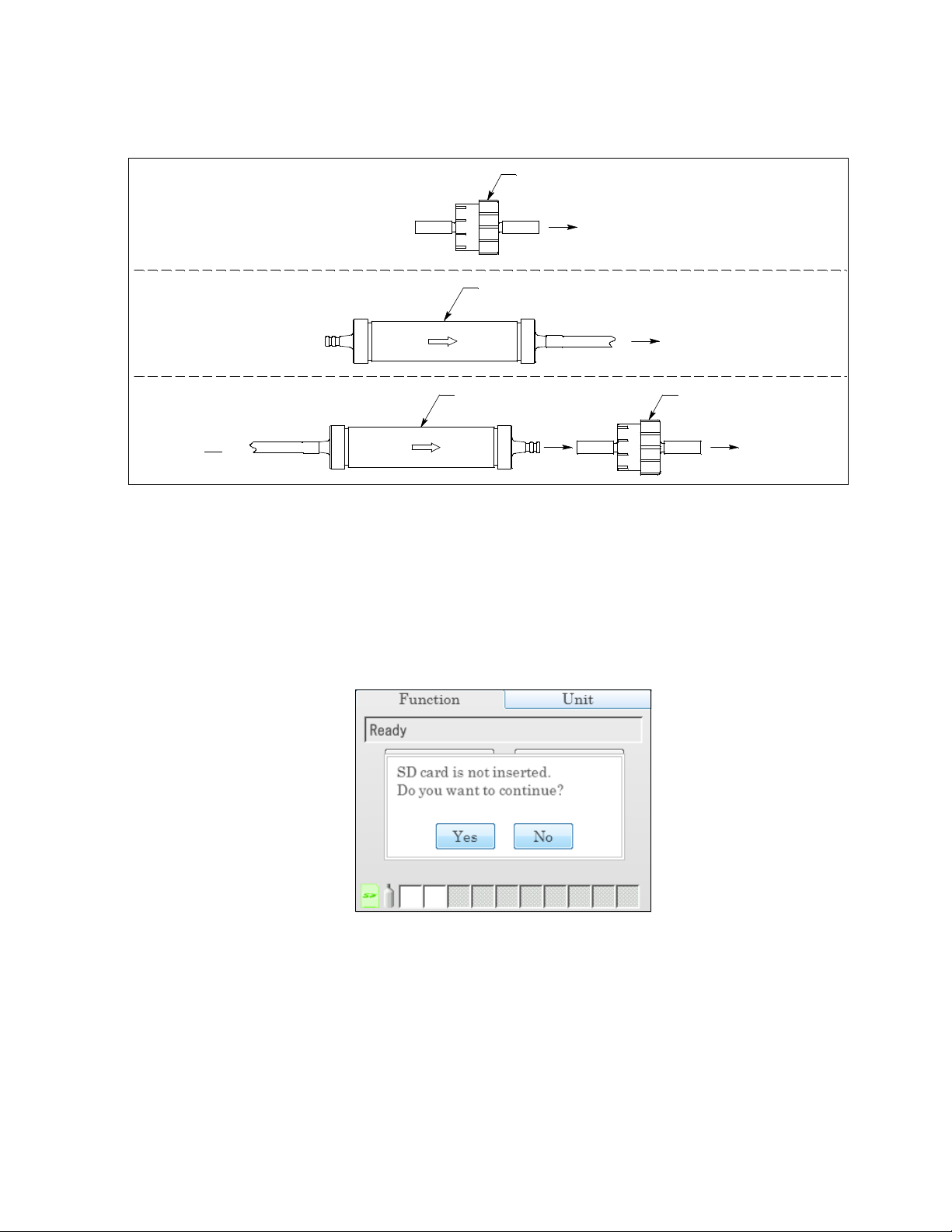
Figure 56: Air Inlet Filters
To Air Filter on
SDM-6000 or SV-3
VOC Zero Filter
(no preferred f low direc tion)
CO2 Scrubber
CO2 Scr ubber
Instrument(s) with
IR CO2 Sensor
Instrument(s) with PID
Sensor and Suspected
Background VOC
To Air Filter on
SDM-6000 or SV-3
To Air Filter on
SDM-6000 or SV-3
VOC Zero Filter
(no preferred flow direc tion)
Instrument(s) with
PID Sensor and
IR
CO2 Sensor
8. Confirm that the appropriate filters are connected to the AIR inlet fitting (if necessary) as
shown below.
9. If necessary, press the Function Tab in the upper left corner to get the Function Tab to appear.
10. Press the BUMP button to initiate a bump test.
If you wish to cancel the bump test, press the BUMP Cancel button in the Function Tab and
press Ye s in the window that appears.
11. If there is no SD card installed, a warning screen will appear. If no SD card is installed, no
test data will be saved. Press Ye s or No to continue with the bump test.
12. Throughout the bump test, the Unit Tab will display the current gas readings along with the
pass/fail status of a bump test or automatic calibration.
Find Quality Products Online at: sales@GlobalTestSupply.com
96 • Chapter 4: Operation
www.GlobalTestSupply.com
Page 97

13. If at any point during the bump test the gas flow to the GX-6000 becomes too low, the bump
Function Tab in Flow Fail Unit Tab in Flow Fail
test will be aborted and the screen will indicate a flow failure.
If a flow failure occurs, confirm all tubing connections are correct, that all lines are clear, and
that the gas in/gas out cover is fully locked onto the GX-6000(s).
Press the BUMP End button in the Function Tab to return to the top level Function Tab
screen.
14. A pre-sample flush will begin. The SDM-6000 will apply fresh air to the GX-6000 for the
time defined by the AIR Flush bump test parameter.
15. The SDM-6000 will perform a fresh air adjustment on the instrument.
a. If the air adjustment is successful, the SDM-6000 will continue as described in step 16
below.
b. If one or more of the sensors fails the fresh air adjustment, the SDM-6000 will abort the
bump test and will not apply calibration gas. If this happens, the Unit Tab will indicate
which channels passed and failed the fresh air adjustment. In the following example, the
O2 channel failed the fresh air adjustment.
In this case, continue to step 22.
Chapter 4: Operation • 97
Find Quality Products Online at: sales@GlobalTestSupply.com
www.GlobalTestSupply.com
Page 98

16. The SDM-6000 will then apply calibration gas in the following order, where applicable: Cl2,
HCN, 4-gas, rest of instrument’s sensors in order of sensor slot. So for a 4-gas + low range
PID + Cl2 instrument, Cl2 will be applied first, then the 4-gas mix, then the low range PID
target gas, regardless of what inlet those gases are assigned to. A 4-gas + high range PID +
SO2 instrument will have gas applied in that sensor order.
17. The SDM-6000 will analyze the results after the end of each gas application. If the bump test
fails and Auto Cal. is set to On, the gas will keep flowing and a calibration will automatically
begin. Calibration gas will continue to be applied so that the total gas application time is the
time defined by the GAS calibration parameter. This time includes the time that the GX-6000
was being bump tested. If the GAS calibration parameter is set to 90 seconds and the GAS
bump test parameter is set to 30 seconds, the GX-6000 will sample gas for an additional 60
seconds to bring the total exposure time to 90 seconds.
Once the calibration is over, the SDM-6000 will continue with the next gas application or
with the post-sample purge, whichever is appropriate.
18. A post-sample purge will begin.
19. If the Alarm Check bump test parameter is selected, an alarm check will begin. The buzzer
will sound, the LEDs will turn on for a few seconds, the vibrator will vibrate, and the SDM6000 will determine if these actions were completed successfully.
20. Once the bump test is over, the Function Tab will display a BUMP End button. To view the
test results, press the Unit button to display the Unit Tab. The displayed results will alternate
between bump test results and alarm check results. The test results will display on the Unit
Tab until you press the BUMP End button in the Function Tab even if the GX-6000 is turned
off.
21. If a printer is connected:
a. If Auto Print is selected, the bump test results will automatically print.
b. If Auto Print is not selected, a Print button will appear in the Function Tab’s Bump Test
screen. Press the Print button to print the bump test results.
22. Press the Function Tab to display the Function Tab if it is not already displayed. Press the
BUMP End button to return to the top level Function Tab screen. The test results that were
being displayed in the Unit Tab will disappear once the BUMP End button is pressed.
23. To perform any other operations, press the BUMP, CAL, or Alarm Check buttons on the
Function Tab.
24. To turn the GX-6000 off:
If the bump test was successful, the GX-6000 will shut off in the time period defined by the
Power Off After Pass parameter in the SDM Window. If the bump test failed, the GX-6000
will shut off in the time period defined by the Auto Power Off parameter in the SDM
Window. If buttons are pressed before the SDM-6000 turns off the GX-6000, the station will
automatically turn the instrument off in the time period defined by the Auto Power Off
parameter after the last button push.
98 • Chapter 4: Operation
Find Quality Products Online at: sales@GlobalTestSupply.com
www.GlobalTestSupply.com
Page 99

To turn off the GX-6000 before it is automatically turned off, press the Detector Off button
in the lower left corner of the station’s Unit Tab. If you have a multi-station installation, only
the master (leftmost) station will have a Unit Tab. The slave stations will only have a main
screen and the Detector Off button will be displayed in the lower left corner.
25. The results of the bump test and calibration (if applicable) will be stored in the SDM-6000’s
SD card.
26. Push the red gas in/gas out cover toward the GX-6000 and then release it. It should return to
its unused state at the top of the SDM-6000.
27. Remove the GX-6000 from the SDM-6000.
28. Repeat step 24 - step 27 for any additional GX-6000s.
Calibration
When a calibration is performed, the docking station performs a fresh air adjustment on a GX6000 and then applies calibration gas to the instrument. The docking station analyzes the
calibration results and determines if the instrument passed the calibration.
Be sure that you have the required calibration cylinders for your sensors. If you are using a 5-gas
cylinder for a special sensor, be sure that the gas inlet parameters are appropriately assigned as
described on pg.53.
NOTE: If you wish to calibrate only the standard four sensors or only the smart sensors,
be sure that the Gas Inlet Parameters are set appropriately as described on pg.53.
To perform a calibration on a GX-6000:
1. Turn on the SDM-6000 system as described on pg.90.
2. Confirm that you have an SD card installed in the system.
NOTE: If an SD card is not installed, then test data and instrument data logger data
downloaded manually or automatically cannot be saved.
3. If necessary, confirm that the calibration parameters are set to the desired values. See pg.49.
4. If a connected GX-6000’s channels does not have an assigned gas inlet or if the gas inlet
setup is not correct, a gas inlet error will occur. A calibration can still be initiated but the
incorrectly set up channel will not be calibrated.
5. If you have a multi-station system and a slave station is turned on but you do not want it to be
included in the testing, deselect the Active box in the lower right corner of the Unit Tab.
6. Verify that the appropriate calibration gas cylinders are connected to the gas fittings on the
left side of the SDM-6000 or to the gas fittings on the SV-3. See pg.38 and pg.41 for
calibration gas cylinder options and calibration gas connection procedures.
7. If you are bump testing a Cl2 sensor, verify that all best practices outlined on pg.27 are being
followed.
Chapter 4: Operation • 99
Find Quality Products Online at: sales@GlobalTestSupply.com
www.GlobalTestSupply.com
Page 100

Figure 57: Air Inlet Filters
To Air Filter on
SDM-6000 or SV-3
VOC Zero Filter
(no preferred f low direc tion)
CO2 Scrubber
CO2 Scr ubber
Instrument(s) with
IR CO2 Sensor
Instrument(s) with PID
Sensor and Suspected
Background VOC
To Air Filter on
SDM-6000 or SV-3
To Air Filter on
SDM-6000 or SV-3
VOC Zero Filter
(no preferred flow direc tion)
Instrument(s) with
PID Sensor and
IR
CO2 Sensor
8. Confirm that the appropriate filters are connected to the AIR inlet fitting (if necessary) as
shown below.
9. If necessary, press the Function Tab in the upper left corner to get the Function Tab to appear.
10. Press the CAL button to initiate a calibration.
If you wish to cancel the calibration, press the CAL Cancel button in the Function Tab and
press Ye s in the window that appears.
NOTE: The CAL button is not active if Manual CAL. is delected in the Config Menu’s
calibration screen.
11. If there is no SD card installed, a warning screen will appear. If no SD card is installed, no
calibration data will be saved. Press Ye s or No to continue with the calibration.
12. Throughout the calibration, the Unit Tab will display the current gas readings along with the
pass/fail status of the calibration.
Find Quality Products Online at: sales@GlobalTestSupply.com
100 • Chapter 4: Operation
www.GlobalTestSupply.com
 Loading...