

Page 1

PT0E-1194
Portable Gas Detector
RX-8000
Operating Manual
(PT0-119)
Find Quality Products Online at: sales@GlobalTestSupply.com
www.GlobalTestSupply.com
Page 2

<Contents>
1. Outline of the Product ........................................................................................................... 2
1-1. Preface .............................................................................................................................. 2
1-2. Purpose of use .................................................................................................................. 2
1-3. Definition of DANGER, WARNING, CAUTION, and NOTE ............................................... 3
2. Important Notices on Safety ................................................................................................. 4
2-1. Danger cases .................................................................................................................... 4
2-2. Warning cases .................................................................................................................. 6
2-3. Names of internal product components ............................................................................. 7
2-4. Safety information (Applicable for ATEX/IECEx) ............................................................... 9
3. Product Components ............................................................................................................ 10
3-1. Main unit and standard accessories .................................................................................. 10
3-2. Names and functions for each part ................................................................................... 12
4. How to Use ........................................................................................................................... 14
4-1. Before using the gas detector ........................................................................................... 14
4-2. Preparation for start-up ..................................................................................................... 14
4-3. Basic operating procedures............................................................................................... 18
4-4. How to start the gas detector ............................................................................................ 19
4-5. How to detect .................................................................................................................... 21
4-6. Modes ............................................................................................................................... 23
4-7. Air calibration mode ........................................................................................................... 24
4-8. Display/setting mode ......................................................................................................... 26
4-9. Pump OFF mode ............................................................................................................... 29
4-10. Manual memory mode .................................................................................................... 30
4-11. How to exit ....................................................................................................................... 31
5. Operations and Functions .................................................................................................... 32
5-1. Fault alarm pattern ............................................................................................................ 32
5-2. Other functions .................................................................................................................. 33
6. Maintenance ......................................................................................................................... 34
6-1. Maintenance intervals and items ....................................................................................... 34
6-2. Gas calibration .................................................................................................................. 36
6-3. How to clean ..................................................................................................................... 40
6-4. Parts replacement ............................................................................................................. 41
7. Storage and Disposal ........................................................................................................... 43
7-1. Procedures to store the gas detector or leave it for a long time ........................................ 43
7-2. Procedures to use the gas detector again ......................................................................... 44
7-3. Disposal of products .......................................................................................................... 44
8. Troubleshooting .................................................................................................................... 45
9. Product Specifications .......................................................................................................... 47
9-1. List of specifications .......................................................................................................... 47
9-2. List of accessories ............................................................................................................. 48
10. Definition of Terms .............................................................................................................. 49
Find Quality Products Online at: sales@GlobalTestSupply.com
www.GlobalTestSupply.com
- 1 - RX-8000
Page 3

1 Outline of the Product 1-1. Preface
1
Outline of the Product
1-1. Preface
Thank you for choosing our portable gas detector RX-8000. Please check that the model number of the
product you purchased is included in the specifications on this manual.
This manual explains how to use the gas detector and its specifications. It contains information required for
using the gas detector properly. Not only the first-time users but also the users who have already used the
product must read and understand the operating manual to enhance the knowledge and experience before
using the indicator/alarm unit.
1-2. Purpose of use
This product is a portable explosion-proof gas detector that measures the concentration of combustible gas
and oxygen in crude oil vapors, etc. in inert gases or atmosphere.
Detection results are not intended to guarantee life or safety in any way.
There are 4 kinds of line up for this mode. Check the specifications before use and conduct gas detection
properly in accordance with purposes.
In addition to this operating manual, an operating manual for the data logger management program (option)
is available for the gas detector. Request RIKEN KEIKI if it is needed.
Product line up
Product Detectable gas
Combustible (HC) Combustible (CH4) Oxygen (O2)
RX-8000 (HC/O2)
RX-8000 (CH4/O2) RX-8000 (HC)
RX-8000 (CH4) HC : Isobutane (i-C4H10) calibration
〇
〇
-
〇 〇
- -
〇
〇
-
Find Quality Products Online at: sales@GlobalTestSupply.com
www.GlobalTestSupply.com
- 2 - RX-8000
Page 4

1 Outline of the Product 1-3. Definition of DANGER, WARNING, CAUTION, and NOTE
1-3. Definition of DANGER, WARNING, CAUTION, and
NOTE
This message indicates that improper handling may cause serious damage on
DANGE R
WARNING
CAUTION
NOTE
life, health or assets.
This message indicates that improper handling may cause serious damage on
health or assets.
This message indicates that improper handling may cause minor damage on
health or assets.
This message indicates advice on handling.
Find Quality Products Online at: sales@GlobalTestSupply.com
www.GlobalTestSupply.com
- 3 - RX-8000
Page 5

2 Important Notices on Safety 2-1. Danger cases
2
Important Notices on
Safety
2-1. Danger cases
DANGER
<About explosion-proof>
Do not modify or change the circuit or structure, etc.
【RX-8000】
When measuring the oxygen concentration, do not measure anything but a mixture of air and
combustible gases or vapors and toxic gases.
When using this gas detector in a hazardous area, take the following countermeasures for
preventing dangers resulting from electrostatic charges.
(1) Wear anti-static clothes and conductive shoes (anti-static work shoes).
(2) For indoor use, use the gas detector while standing on a conductive work floor (with a
leakage resistance of 10 MΩ or less).
IP protection class: IP20
* IP20 is a protection class on explosion-proof certification. The IP protection class is compliant
to IP67 level by factory default.
Make sure that the product model on the nameplate is correct.
Inappropriate combinations of models deviate from the range of explosion-proof certification.
The nameplate shows the followings as well as the product model.
Product model : Main unit: RX-8000 (TC20782)
Dry battery unit: BUD-8000(R)(TC20783)
Lithium ion battery unit: BUL-8000(R)(TC20784),BUL-8000(R1)(TC21112)
Manufacturer : RIKEN KEIKI Co., Ltd.
Explosion proof class : 【RX-8000】Ex ia IIC T4
【BUL-8000(R), BUL-8000(R1), BUD-8000(R)】 Ex ia IIC T4
Ambient temperature : -20 to 50ºC
Charging terminal rating : 【BUL-8000(R), BUL-8000(R1)】 Allowable voltage AC250V 50/60Hz
Warnings : 【BUL-8000(R), BUL-8000(R1), BUD-8000(R)】 Inhibit to take off
battery unit in non-hazardous area.
Nameplate location
Find Quality Products Online at: sales@GlobalTestSupply.com
RX-8000
www.GlobalTestSupply.com
- 4 -
Page 6

2 Important Notices on Safety 2-1. Danger cases
DANGER
< About explosion-proof of the main unit>
The battery units that can be connected are the BUL-8000(R)(TC20784), BUL-8000(R1)(TC21112)
or BUD-8000(R)(TC20783).
The specifications of the gas detector are as follows:
Pump circuit : Allowable voltage of 4.95 V, allowable current of 1.12 A, and
allowable power of 1138 mW
Infrared detection circuit : Allowable voltage of 4.95 V, allowable current of 0.834 A, and
allowable power of 853 mW
Buzzer circuit : Allowable voltage of 4.95 V, allowable current of 0.431 A, and
allowable power of 441 mW
Main circuit : Allowable voltage of 4.95 V, allowable current of 0.717 A, and
allowable power of 733 mW
Backup circuit : 3.0 VDC, 10 µA
Ambient temperature :-20degree C to +50degree C
< About explosion-proof of the battery unit >
The main unit that can be connected is RX-8000(TC20782) only.
The use with unspecified main units deviates from the range of explosion-proof certification.
The specifications of the BUL-8000(R), BUL-8000(R1) are as follows:
Pump circuit : Maximum voltage of 4.25 V, maximum current of 1.12 A, and
maximum power of 901 mW
Infrared detection circuit : Maximum voltage of 4.25 V, maximum current of 0.768 A, and
maximum power of 618 mW
Buzzer circuit : Maximum voltage of 4.25 V, maximum current of 0.410 A, and
maximum power of 330 mW
Main circuit : Maximum voltage of 4.25 V, maximum current of 0.653 A, and
maximum power of 526 mW
Battery charging contact : Allowable current of 250 VAC
Ambient temperature : -20degree C to +50degree C
*Chargin has to be done with the dedicated AC adaptor in non-hazardous area.
And, the temperature should be beteen 0degree C and +40degree C.
The specifications of the BUD-8000(R) are as follows:
Pump circuit : Maximum voltage of 4.95 V, maximum current of 1.12 A, and
maximum power of 1138 mW
Infrared detection circuit : Maximum voltage of 4.95 V, maximum current of 0.834 A, and
maximum power of 853 mW
Buzzer circuit : Maximum voltage of 4.95 V, maximum current of 0.431 A, and
maximum power of 441 mW
Main circuit : Maximum voltage of 4.95 V, maximum current of 0.717 A, and
maximum power of 733 mW
Power supply : 4.5 VDC, 150 mA (LR6 3 pcs)
Ambient temperature : -20degree C to +50degree C
Do not attach and remove the battery unit or batteries in the dry battery unit in a hazardous
location.
Use specified AA alkaline batteries (LR6 TOSHIBA) for the dry battery unit.
< About use >
While conducting measurement in a manhole or confined space, do not lean over or look into the
manhole or closed space. It may lead to dangers because oxygen-deficient air or other gases
may blow out.
Oxygen-deficient air or other gases may blow out from the gas exhausting outlet. Never inhale
the air or gases.
High-concentration (more than LEL) gases may blow out. Never use fire near the gas detector.
Find Quality Products Online at: sales@GlobalTestSupply.com
www.GlobalTestSupply.com
- 5 - RX-8000
Page 7

2 Important Notices on Safety 2-2. Warning cases
2-2. Warning cases
WARNING
< Sampling point pressure >
The gas detector is designed to draw gases around it under the atmospheric pressure. If
excessive pressure is applied to the gas inlet and outlet (GAS IN, GAS OUT) of the gas detector,
detected gases may leak out from its inside and may cause dangerous conditions. Be sure that
excessive pressure is not applied to the detector while used.
Do not connect the gas sampling hose directly to a location with a pressure higher than the
atmospheric pressure. The internal piping system may be damaged.
< Handling of sensor >
Do not disassemble the galvanic cell type sensor because it contains electrolyte. Electrolyte may
cause severe skin burns if it contacts skin, while it may cause blindness if its contacts eyes.
If electrolyte is adhered on your clothes, that part on your clothes is discolored or its material is
decomposed. If contact occurs, rinse the area immediately with a large quantity of water.
< Fresh air adjustment in atmosphere >
When the air calibration is performed in the atmosphere, check the atmosphere for freshness
before beginning the air calibration. If other gases exist, the adjustment cannot be performed
properly, thus leading to dangers when the gas leaks.
< Battery level check >
Before use, check that there remains sufficient battery power. When the gas detector is used for
the first time or is not used for a long period, the batteries may be exhausted. Either fully charge
the batteries or replace them with new ones before use.
If a low battery voltage alarm is triggered, gas detection cannot be conducted. If the alarm is
triggered during use, turn off the power and promptly charge the batteries in a non-hazardous
area.
< Others >
Do not throw the gas detector into fire.
Do not wash the gas detector in a washing machine or ultrasonic cleaner.
Do not block the buzzer sound hole. No alarm sound can be heard.
Do not remove the battery unit while the power is ON.
Do not drop or give shock to the gas detector by, for example, relocating the gas detector with a
water trap, an optional accessory, attached. The gas inlet may be damaged.
Find Quality Products Online at: sales@GlobalTestSupply.com
RX-8000 - 6 -
www.GlobalTestSupply.com
Page 8

2 Important Notices on Safety 2-3. Names of internal product components
2-3. Names of internal product components
CAUTION
< Do not use the gas detector where it is exposed to oil, chemicals, etc. Do not submerge the gas
detector under water on purpose. >
Do not use in a place where the gas detector is exposed to liquids such as oil and chemicals.
The gas detector, being compliant to IP67, is not water-pressure-resistant. Do not use the gas
detector where a high water pressure is applied to it (under a faucet, shower, etc.) or submerge it
under water for a long time. The gas detector is water-proof only in fresh water and running
water, and not in hot water, salt water, detergent, chemicals, human sweat, etc.
The gas inlet and outlet are not water-proof. Be careful not to let water such as rainwater get into
these parts. Because this may cause trouble and gas cannot be detected.
Do not place the gas detector where water or dirt gets accumulated. The gas detector placed at
such a location may malfunction due to water or dirt that gets into the buzzer opening, gas inlet,
etc.
Note that drawing in dirty water, dust, metallic powder, etc. will significantly deteriorate the
sensor sensitivities. Be careful when the gas detector is used in an environment where these
elements exist.
< Do not use the gas detector in a place where the temperature drops below -20ºC or rises over
50ºC. >
The operating temperature of the gas detector is -20 to 50ºC. Do not use the gas detector at
higher temperatures, humidities, and pressures or at lower temperatures than the operating
range.
Avoid long-term use of the gas detector in a place where it is exposed to direct sunlight.
Do not store the gas detector in a sun-heated car.
< Observe the operating restrictions to prevent condensation inside the gas detector or gas
sampling hose. >
Condensation formed inside the gas detector or gas sampling hose causes clogging or gas
adsorption, which may disturb accurate gas detection. Thus, condensation must be avoided. In
addition to the operating environment, carefully monitor the temperature/humidity of the
sampling point to prevent condensation inside the gas detector or gas sampling hose. Please
observe the operating restrictions.
< Do not use a transceiver near the gas detector. >
Radio wave from a transceiver near the gas detector may disturb readings. If a transceiver is
used, it must be used in a place where it disturbs nothing.
Do not use the gas detector near a device that emits strong electromagnetic waves
(high-frequency or high-voltage devices).
< Verify that the pump driving indicator is rotating before using the gas detector. >
If the pump driving indicator is not rotating, gas detection cannot be performed properly. Check
whether the flow rate is lost.
< Never fail to perform a regular maintenance. >
Since this is a safety unit, a regular maintenance must be performed to ensure safety.
Continuing to use the detector without performing a maintenance will compromise the sensitivity
of the sensor, thus resulting in inaccurate gas detection.
Find Quality Products Online at: sales@GlobalTestSupply.com
www.GlobalTestSupply.com
- 7 - RX-8000
Page 9

2 Important Notices on Safety 2-3. Names of internal product components
CAUTION
< Others >
Pressing switches unnecessarily may change the settings, preventing alarms from activating
correctly. Operate the gas detector using only the procedures described in this operating
manual.
Do not drop or give shock to the gas detector. The water-proof and explosion-proof properties
and accuracy may be deteriorated.
Do not use the gas detector while recharging it.
When you measure concentrations of oxygen in inert gases for a long time, the carbon dioxide
concentration in the air must be 15% or less. When you use the gas detector in the inert gas with
a carbon dioxide concentration of 15% or higher, perform measurement in as short time as
possible. Using the gas detector under high concentrations for a long time may shorten the life of
the oxygen sensor.
Find Quality Products Online at: sales@GlobalTestSupply.com
RX-8000 - 8 -
www.GlobalTestSupply.com
Page 10

2 Important Notices on Safety 2-4. Safety information (Applicable for ATEX/IECEx)
2-4. Safety information (Applicable for ATEX/IECEx)
Observe the followings to maintain an explosion-proof system.
<Overseas Specifications>
Outline of the product
This product is a portable explosion-proof gas detector that measures the concentration of
combustible gas and oxygen in crude oil vapors, etc. in inert gases or atmosphere.
Gases are drawn by the built-in pump.
As a power supply, either Li-ion battery unit (BUL-8000(R), BUL-8000(R1)) or dry battery unit
(BUD-8000(R)) can be used.
The battery unit can be replaced by users.
Technical data
Explosion-proof
specifications
Electrical
specifications
Certificate
numbers
Applied
standards
Precautions
How to read
instruction
number
Manufacturer
Explosion-proof class ExiaIICT4Ga
II1GExiaIICT4Ga
Ambient temperature -20 to 50°C
Ambient temperature
(for charging)
Power supply
IECEX IECExDEK13.0091
ATEX DEKRA13ATEX0228
0 to 40°C
About lithium ion battery unit (BUL-8000(R),
BUL-8000(R1))
Two Lithium ion cells of BP-8000 (Maxell
INR18650PB1. Um=250V) are connected in parallel
to the Lithium ion battery unit.
About dry battery unit (BUD-8000(R))
TOSHIBA AA alkaline batteries (LR6) can be used.
Maxell CR1220 battery is used for backup.
IEC60079-0:2011
IEC60079-11:2011
IEC60079-26:2006
EN60079-0:2012
EN60079-11:2012
EN60079-26:2007
Do not charge the Lithium ion battery unit in a
hazardous location.
Charge the Lithium ion battery unit using the
dedicated charger.
Do not replace the battery unit in a hazardous
location.
Do not replace batteries in the dry battery unit in a
hazardous location.
Do not modify or change the circuit or structure, etc.
Use either Lithium ion battery unit (BUL-8000(R),
BUL-8000(R1)) or dry battery unit (BUD-8000(R)).
Dry batteries used for the dry battery unit
(BUD-8000(R)) are TOSHIBA AA alkaline batteries
(LR6).
INST.No.0 0 000 0000 00
A B C D E
A: Manufacturing year (0-9)
B: Manufacturing month (1-9, XYZ for Oct.-Dec.)
C: Manufacturing lot
D: Serial number
E: Manufacturing code
RIKEN KEIKI CO., LTD.
2-7-6 Azusawa, Itabashi-ku, Tokyo, 174-8744 Japan
Web site: http://www.rikenkeiki.co.jp/
Find Quality Products Online at: sales@GlobalTestSupply.com
www.GlobalTestSupply.com
- 9 - RX-8000
Page 11

3 Product Components 3-1. Main unit and standard accessories
3
Product Components
3-1. Main unit and standard accessories
After opening the package, check the main unit and accessories.
If anything in the following list is not included, contact RIKEN KEIKI.
<Main Unit>
RX-8000
main unit
Li-ion battery
unit
DANGER
< About explosion-proof >
Do not modify or change the circuit or structure, etc.
When measuring the oxygen concentration, do not measure anything but a mixture of air and
combustible gases or vapors and toxic gases.
When using this gas detector in a hazardous area, take the following countermeasures for
preventing dangers resulting from electrostatic charges.
(1) Wear anti-static clothes and conductive shoes (anti-static work shoes).
(2) For indoor use, use the gas detector while standing on a conductive work floor (with a
leakage resistance of 10 MΩ or less).
IP protection class: IP20
* IP20 is a protection class on explosion-proof certification. The IP protection class is compliant
to IP67 level by factory default.
< About explosion-proof of the main unit >
The battery units that can be connected are the BUL-8000(R)(TC20784), BUL-8000(R1)(TC21112)
or BUD-8000(R) (TC20783).
The use with unspecified battery units deviates from the range of explosion-proof certification.
<Standard Accessories>
AC powered charger : 1
Gas sampling probe
and gas sampling hose : 1
Filter tube(CF-8385) : 1
Relay tube : 1
Shoulder strap : 1
Filter tube fixing belt : 1
Operating manual
Product warranty
Find Quality Products Online at: sales@GlobalTestSupply.com
RX-8000 - 10 -
www.GlobalTestSupply.com
Page 12

3 Product Components 3-1. Main unit and standard accessories
DANGER
The specifications of the gas detector are as follows:
Pump circuit : Allowable voltage of 4.95 V, allowable current of 1.12 A, and
allowable power of 1138 mW
Toxic gas sensor circuit : Allowable voltage of 4.95 V, allowable current of 0.834 A, and
allowable power of 853 mW
Buzzer circuit : Allowable voltage of 4.95 V, allowable current of 0.431 A, and
allowable power of 441 mW
Main circuit : Allowable voltage of 4.95 V, allowable current of 0.717 A, and
allowable power of 733 mW
Backup circuit : 3.0 VDC, 10 µA
Ambient temperature :-20 degree C to +50 degree C
< About explosion-proof of the battery unit >
The main unit that can be connected is RX-8000(TC20782) only.
The use with unspecified main units deviates from the range of explosion-proof certification.
The specifications of the BUD-8000(R) are as follows:
Pump circuit : Maximum voltage of 4.95 V, maximum current of 1.12 A, and
maximum power of 1138 mW
Infrared detection circuit : Maximum voltage of 4.95 V, maximum current of 0.834 A, and
maximum power of 853 mW
Buzzer circuit : Maximum voltage of 4.95 V, maximum current of 0.431 A, and
maximum power of 441 mW
Main circuit : Maximum voltage of 4.95 V, maximum current of 0.717 A, and
maximum power of 733 mW
Power supply : 4.5 VDC, 150 mA (LR6 3 pcs)
Ambient temperature :-20 degree C to +50 degree C
The specifications of the BUL-8000(R), BUL-8000(R1)(TC21112) are as follows:
Pump circuit : Maximum voltage of 4.25 V, maximum current of 1.12 A, and
maximum power of 901 mW
Infrared detection circuit : Maximum voltage of 4.25 V, maximum current of 0.768 A, and
maximum power of 618 mW
Buzzer circuit: Maximum voltage of 4.25 V, maximum current of 0.410 A, and
maximum power of 330 mW
Main circuit : Maximum voltage of 4.25 V, maximum current of 0.653 A, and
maximum power of 526 mW
Battery charging contact : Allowable current of 250 VAC
Ambient temperature :-20 degree C to +50 degree C
Do not attach and remove the battery unit or batteries in the dry battery unit in a hazardous
location.
Use specified AA alkaline batteries (LR6 TOSHIBA) for the dry battery unit.
NOTE
There are the following two combinations of battery units. The
following information is printed on the battery unit for the sake of
identification to prevent a mistake in combinations.
Lithium ion battery unit : BUL-8000(R)(TC20784)
BUL-8000(R1)(TC21112)
Dry battery unit : BUD-8000(R)(TC20783)
Additionally, a nameplate indicating a compatible model is affixed
on the top of the battery unit.
Check this information and use a correct
combination.
Find Quality Products Online at: sales@GlobalTestSupply.com
www.GlobalTestSupply.com
- 11 - RX-8000
Printing for
identification
Page 13

3 Product Components 3-2. Names and functions for each part
3-2. Names and functions for each part
<Main Unit>
(3) Alarm LED arrays
(4) Infrared communication port
(3) Alarm LED arrays
(2) Buzzer sound
opening
(3) Alarm LED arrays
(1) LCD display
(5) ▲/AIR switch
(6) ▼/PUMP switch
(10) Gas outlet
Name Function
(7) PEAK/ESC switch
(8) POWER/ENTER switch
(11) Recharging jack cover
(13) Battery unit screws
(2) Buzzer sound opening
(9) Gas inlet
(12) Recharging indicator lamp
(1) LCD display Displays gas concentrations, alarms, etc.
(2) Buzzer sound opening Emits a buzzer sound at an alarm. (Do not block it.)
(3) Alarm LED arrays The lamp blinks in response to an alarm.
(4) Infrared communication port
(5) ▲/AIR switch
Used to carry out data communications with a PC in data logger
mode.
Keep this switch pressed to perform fresh air calibration. It is used
to increase numerical values.
(6) ▼/PUMP switch Turns on and off the pump. It is used to decrease numerical values.
(7) PEAK/ESC switch Press this switch to change between display modes.
(8) POWER/ENTER switch Turns on and off the power.
(9) Gas inlet Connect a sampling hose to this port.
(10) Gas outlet Exhausts the gas drawn into the gas detector. (Do not block it.)
(11) Recharging jack cover
(12) Recharging indicator lamp
Remove this cover to connect an AC powered charger and
recharge the batteries.
Lights up in red during recharging and goes off when recharging is
completed.
(13) Battery unit screws Turn these screws to detach and replace the battery unit.
Find Quality Products Online at: sales@GlobalTestSupply.com
RX-8000
www.GlobalTestSupply.com
- 12 -
Page 14

3 Product Components 3-2. Names and functions for each part
CAUTION
Do not jab the buzzer opening with a sharp-pointed item. The unit may malfunction or get
damaged, allowing water or foreign matter, etc. to get inside.
Do not remove the panel sheet on the display. The water-proof and dust-proof performances will
be deteriorated.
Do not affix a label on the infrared port. Infrared communications can no longer be conducted.
< LCD Display >
(1) Pilot indicator
(2) Combustible gas
concentration
digital and bar display
(3) Battery level icon
Name Function
(4) Pump driving
indicator
(5) Oxygen
concentration
digital and bar
(1) Pilot indicator Displays the operating status in the detection mode. Normal: Blinking
Combustible gas
(2)
concentration
digital and bar display
(3) Battery level icon
(4) Pump driving indicator Displays the drawing status in the detection mode. Normal: Rotating
Oxygen concentration
(5)
digital and bar display
Displays the gas concentration as a numeric value and a level in the bar
graph.
Displays the battery level. See the information below for the meanings of
battery level icons.
Displays the gas concentration as a numeric value and a level in the bar
graph.
NOTE
The meanings of battery level icons are as follows:
Sufficient / :Low / :Needs charging
If the battery level is lower than the above, the inside of the battery icon starts to blink ( ).
NOTE
The gas alarm function is an optional setting.
When NO ALARM lights up, no gas alarm pattern is performed.
No ALARM display
Find Quality Products Online at: sales@GlobalTestSupply.com
www.GlobalTestSupply.com
- 13 - RX-8000
Page 15

4 How to use 4-1. Before using the gas detector
4
How to Use
4-1. Before using the gas detector
Not only the first-time users but also the users who have already used the product must follow the operating
precautions.
Ignoring the precautions may damage the gas detector, resulting in inaccurate gas detection.
4-2. Preparation for start-up
Before starting gas detection, read and understand the following precautions. Ignoring these precautions
may prevent correct gas detection.
Check that the main unit, relay tube, filter tube, gas sampling hose, and gas sampling probe are connected
properly in this order.
Check that the battery level is sufficient.
Check that the filter and filter tube in the gas sampling probe are free of dust or clogging.
Check that there is no bend or hole in the gas sampling hose and relay tube.
< Recharging of Batteries >
(when the Li-ion battery unit BUL-8000(R), BUL-8000(R1) are used)
When the gas detector is used for the first time, or when the battery level is low, be sure to use the
accessory AC powered charger to charge the batteries.
CAUTION
Use the dedicated AC powered charger.
Charge the battery unit in a non-hazardous area.
Charge the battery unit at ambient temperatures between 0 to 40ºC.
Do not use the gas detector while charging it. Correct measurements cannot be obtained.
Furthermore, the batteries get deteriorated more quickly and may have shorter life.
The charger is neither water-proof nor dust-proof. Do not recharge the batteries while the gas
detector is wet.
The AC powered charger is not explosion-proof.
Find Quality Products Online at: sales@GlobalTestSupply.com
www.GlobalTestSupply.com
- 14 - RX-8000
Page 16

4 How to Use 4-2. Preparation for start-up
p
j
A
(1) Open the charging jack cover of the gas detector.
CAUTION
Do not pull the charging jack cover too hard. It may get
damaged.
(2) Put the plug of the AC powered charger into the recharging
jack of the gas detector.
(3) Connect the AC powered charger to the wall electric outlet.
When charging is started, the charging indicator lamp lights up
(red).
(Charging time: Three hours at the maximum until the
batteries are fully charged)
(4) When charging is completed, the charging indicator lamp goes off.
(5) When charging is completed, disconnect the AC powered charger from the wall electric outlet.
(6) Pull out the AC powered charger plug from the power jack of the
gas detector and reattach the recharging jack cover. Put the
charging jack cover as far as it will go.
CAUTION
Do not use the gas detector with the recharging jack cover detached. Dust or water may get into
the gas detector, causing it to malfunction. Replace the charging jack cover if it is damaged.
If the charging jack cover is not completely closed, water may get in from the power jack. The
same thing occurs if a minute foreign substance is caught beneath the knob.
Disconnect the AC
owered charger from the wall electric outlet while it is not in use.
Recharging
ack
C powered
charger
Plug
Insert the plug of the AC
powered charger into the
recharging jack.
NOTE
During recharging, the battery pack may get hot, but this is not an abnormality.
The temperature of the gas detector is high immediately after charging is completed. Allow at least 10
minutes or more for the unit to cool down before using it. Otherwise, correct measurements may not be
obtained.
When fully recharged batteries are recharged again, the recharging indicator lamp does not go on.
<Attaching Batteries>
(when the dry battery unit BUD-8000(R) is used)
When the gas detector is used for the first time, or when the battery level is low, attach new AA alkaline
batteries.
CAUTION
<Replacement>
Turn off the power of the gas detector before replacing the batteries.
Replace the batteries in a non-hazardous area.
Replace all of the three batteries with new ones at one time.
Pay attention to the polarities of the batteries.
If the battery cover fixing screw is not completely tightened, the dry batteries may drop off or
water may get in through the clearance.
Water may also get in if a minute foreign substance is caught beneath the battery unit.
<Batteries>
Use AA alkaline batteries.
Chargeable batteries cannot be used.
Find Quality Products Online at: sales@GlobalTestSupply.com
www.GlobalTestSupply.com
- 15 - RX-8000
Page 17

4 How to Use 4-2. Preparation for start-up
(1) Using a flathead screwdriver or coin, turn the battery
cover fixing screw counterclockwise to open the battery
Battery cover
Battery cover f ixing
screw
cover.
(2) Paying attention to the polarities of batteries, replace all
the three batteries with new ones.
(3) Close the battery cover and tighten the battery cover
fixing screw.
Batteries
Polarity indication
of batteries
<Releasing and Attaching the Battery Unit>
(1) Loosen the two battery unit screws.
(They need not be completely detached.)
(2) Detach the battery unit.
(3) Attach a new battery unit.
NOTE
Make sure that the battery unit is installed in correct orientation by
checking the locations of the connection terminal and projection
portions.
(4) Securely tighten the two battery unit screws.
CAUTION
Turn off the power of the gas detector before replacing the battery unit.
Attach and remove the battery unit in a non-hazardous area.
If the battery unit screw is not completely tightened, the battery unit may drop off or water may
get in through the clearance. Water may also get in if a minute foreign substance is caught
beneath the battery unit.
Do not damage the rubber seal.
To maintain the water-proof and dust-proof performances, it is recommended to replace the
rubber seal every two years, whether or not it has an abnormality.
Connection
terminal
Battery unit screw
Bottom of Gas
Detector
Find Quality Products Online at: sales@GlobalTestSupply.com
RX-8000
www.GlobalTestSupply.com
- 16 -
Page 18

4 How to Use 4-2. Preparation for start-up
<Connection of Gas Sampling Probe and Gas Sampling Hoses>
Attach the gas sampling hose to the gas sampling probe.
Connect the relay tube, filter tube, gas sampling hose, and gas sampling probe in this order securely to
the gas inlet (GAS IN) of the main unit.
NOTE
Connect each part, such as to the gas inlet (GAS IN), until it
clicks into place to ensure connection.
CAUTION
Use only a gas sampling hose specified by RIKEN KEIKI.
Use the gas detector with the gas sampling probe connected so that no foreign substance is
drawn into it.
Connect a gas sampling probe and a gas sampling hose by fastening them manually without
using any tool. If they are fastened too tightly using a tool, the plastic part of the gas sampling
probe may be broken.
Find Quality Products Online at: sales@GlobalTestSupply.com
www.GlobalTestSupply.com
- 17 - RX-8000
Page 19

4 How to Use 4-3. Basic operating procedures
4-3. Basic operating procedures
Normally, the detection mode is used for normal operations. (The detection mode is activated after the
power is turned on.)
<<Detection Mode>>
<<Fault Alarm Status>>
(Self-latching)
PEAK+▲
<<Manual Memory Mode>>
LCD
AIR (long pressing)
<<Air Calibration Mode>>
▼+▲ (long pressing)
<<Span Calibration Mode>>
PEAK
<<Display/Setting Mode>>
PUMP (long pressing) : Stop operation
PUMP (short pressing) : Resume
<<Pump ON/OFF Setting>>
Find Quality Products Online at: sales@GlobalTestSupply.com
RX-8000
www.GlobalTestSupply.com
- 18 -
Page 20

4 How to Use 4-4. How to start the gas detector
4-4. How to start the gas detector
Keep the POWER switch pressed for three seconds or more to turn on the power.
After the display automatically switches between Date/Time, Battery Voltage, and others and self diagnosis
is conducted, the gas detector enters the detection mode.
<<Start-up Procedure>>
Keeping the POWER switch
pressed for three seconds or
more
↓
LCD display
All LCDs Light Up.
* Keep it pressed until the alarm
lamp lights up and the buzzer
sounds once (Beep).
↓
Date/Time Display
↓
Battery Voltage Display
↓
Gas Name Display
↓
Full Scale Display
↓
ID Display
↓
Find Quality Products Online at: sales@GlobalTestSupply.com
www.GlobalTestSupply.com
- 19 - RX-8000
Page 21

4 How to Use 4-4. How to start the gas detector
↓
Checking connection of filters
After checking the connection of
filters, press the ENTER switch.
↓
Warm-up
Warm-up is performed for about
30 seconds.
The number displayed in the
center of the screen starts
counting down.
⇔
* Until confirmed, the confirmation
screens are displayed in turn as
shown in the above picture.
↓
Detection Mode
* The buzzer sounds twice (Beep,
beep).
CAUTION
After start-up, perform air calibration before performing gas detection (See "4-7. Air calibration
mode").
NOTE
A sensor abnormality alarm is issued before the detection mode is entered if there is any abnormality
in the sensor. Press the ▼ switch. This will reset the sensor abnormality alarm temporarily, set the gas
concentration display that was abnormal on the sensor to ---, and start gas detection. However, notify
the abnormality to RIKEN KEIKI promptly. Gas for which there was an abnormality in the sensor
cannot be detected. However, the alarm cannot be reset if there is an abnormality in all the sensors.
If there is an abnormality in the built-in clock, a fault alarm FAIL CLOCK may be issued. Press the ▼
switch. The fault alarm is temporarily reset, and measurement is started with incorrect clock time.
NOTE
At a low temperature, the pump may need to be warmed up.
In this case, the screen will be as shown on the right after the battery voltage is
displayed (Max 60 seconds).
Find Quality Products Online at: sales@GlobalTestSupply.com
RX-8000 - 20 -
www.GlobalTestSupply.com
Page 22

4 How to Use 4-5. How to detect
4-5. How to detect
In the detection mode, put the gas sampling probe close to the detection area and take the reading on the
display.
<- Display example
HC concentration: 0.0%LEL
O2 concentration: 20.9%
Battery level: Sufficient
* HC: The acronym of HydroCarbons. In this gas
detector, combustible gas concentration is
displayed in isobutane conversion.
DANGER
While conducting measurement in a manhole or confined space, do not lean over or look into the
manhole or closed space. It may lead to dangers because oxygen-deficient air or other gases
may blow out.
Oxygen-deficient air or other gases may blow out from the gas exhausting outlet. Never inhale
the air or gases.
High-concentration (more than LEL) gases may blow out. Never use fire near the gas detector.
When measuring the oxygen concentration, do not measure anything but a mixture of air and
combustible gases or vapors and toxic gases.
WARNING
The gas detector is designed to draw gases around it under the atmospheric pressure. If
excessive pressure is applied to the gas inlet and outlet (GAS IN, GAS OUT) of the gas detector,
detected gases may leak out from its inside and may cause dangerous conditions. Be sure that
excessive pressure is not applied to the detector while used.
Do not connect the sampling hose directly to a location with a pressure higher than the
atmospheric pressure. The internal piping system may be damaged.
When the fresh air adjustment is performed in the atmosphere, check the atmosphere for
freshness before beginning the adjustment. If other gases exist, the adjustment cannot be
performed properly, thus leading to dangers when the gas leaks.
Issuance of a gas alarm indicates that there are extreme dangers. Take proper actions based on
your judgment.
Before use, check that there remains sufficient battery power. When the gas detector is used for
the first time or is not used for a long period, the batteries may be exhausted. Either fully charge
the batteries or replace them with new ones before use.
If a low battery alarm occurs, gas detection cannot be conducted. If the alarm is triggered during
use, turn off the power and promptly charge the batteries in a non-hazardous area.
Do not block the buzzer sound hole. No alarm sound can be heard.
Find Quality Products Online at: sales@GlobalTestSupply.com
www.GlobalTestSupply.com
- 21 - RX-8000
Page 23
4 How to Use 4-5. How to detect
CAUTION
Before performing gas detection, attach the gas sampling probe provided with the gas detector
to prevent disturbances by air dust.
When you measure concentrations of oxygen in inert gases for a long time, the carbon dioxide
concentration in the air must be 15% or less. When you use the gas detector in the inert gas with
a carbon dioxide concentration of 15% or higher, perform measurement in as short time as
possible. Using the gas detector under high concentrations for a long time may shorten the life of
the oxygen sensor.
NOTE
In a low-temperature environment, the operating time is shortened due to the battery performance
property.
At a low temperature, the response of the LCD display may get slow down.
If a combustible gas with a higher concentration than %LEL is drawn, some gas may remain in the gas
sampling hose due to adsorption in the hose, gas sampling probe, etc. After drawing a
high-concentration combustible gas, clean the gas detector to remove the adsorbed gas (draw fresh
air and check that the reading becomes zero).
Performing fresh air calibration before cleaning it completely will result in inaccurate adjustment, giving
adverse influence on measurement. In such a case, remove the gas sampling hose before performing
fresh air calibration to avoid inaccurate adjustment.
NOTE
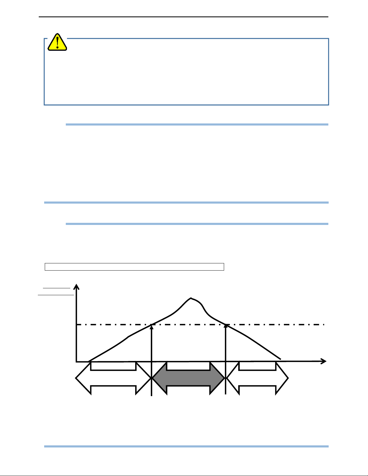
<About Range Switching Point>
The display automatically switches to the vol% range when the concentration of a detected combustible
gas exceeds 100%LEL. When the concentration drops, the display returns to the %LEL range again. The
following shows an example of switching timing.
Diagram example of gas concentrations and range switching timing
HC / CH4
concentration
100%LEL
(HC:1.8vol%)
(CH4 5.0vol%
* HC: The acronym of HydroCarbons. Because combustible gas concentration is displayed in isobutane or
CH4 conversion in this detector, the range switching point is LEL 1.8 vol% of isobutane or 5.0% of
methane respectively.
%LEL range
Switching point
vol% range
Switching point
%LEL range
Find Quality Products Online at: sales@GlobalTestSupply.com
RX-8000 - 22 -
www.GlobalTestSupply.com
Page 24

4 How to Use 4-6. Modes
4-6. Modes
Details on each mode are provided as follows.
Mode Item LCD display Details
Detection Mode - Concentration display Normal state
Air Calibration
Mode
Display and
Setting Mode
- AIR CAL Performs the zero adjustment.
Peak Display PEAK Displays the maximum concentration (or
minimum concentration for oxygen
display) detected during measurement
from power-on to the present.
Full Scale
Display/Alarm
Setpoint
Display/Alarm
Tes t
[Optional
Setting]
Clock Display Displays the current time.
ID Display ID Displays an ID if it has been set in
ALARM-P * The gas alarm function is an optional
setting.
advance. Also used to change or set an
ID.
Log Data
Display
Pump OFF
Mode
Manual Memory
Mode
Find Quality Products Online at: sales@GlobalTestSupply.com
- PUMP OFF Used to turn on/off the pump operations.
- REC.DATA Any instantaneous value can be
www.GlobalTestSupply.com
REC.DATA Displays data recorded to the manual
memory.
recorded.
- 23 - RX-8000
Page 25

4 How to Use 4-7. Air calibration mode
g
4-7. Air calibration mode
Detection Mode
Keep the AIR switch
pressed.
↓
When the AIR switch is kept
pressed, the display
changes to AdJ - HOLD AIR.
↓
↓
When RELEASE is
displayed, release the AIR
switch.
↓
Detection Mode
When the air calibration is
successfully completed, it
returns to the detection
mode.
WARNING
When the air calibration is performed in the atmosphere, check the atmosphere for freshness before
beginning the air calibration. If other gases exist, the adjustment cannot be performed properly, thus
leadin
CAUTION
Perform air calibration under pressure and temperature/humidity conditions close to those in the
Perform air calibration after the reading is stabilized.
If there is a sudden temperature change of 15℃ or more between the storage and operation
to dangers when the gas leaks.
operating environment and in fresh air.
locations, turn on the power of the gas detector, let it leave for about 10 minutes in a similar
environment to the operation location, and perform air calibration in fresh air before using it.
Find Quality Products Online at: sales@GlobalTestSupply.com
RX-8000 - 24 -
www.GlobalTestSupply.com
Page 26

4 How to Use 4-7. Air calibration mode
NOTE
If the air calibration fails, FAIL - AIR CAL is displayed along with the name of
gas sensor which has become faulty.
Press the ▼ switch to reset the fault alarm (calibration failure). In this case,
the value before calibration is displayed.
If HC sensor is faulty
Find Quality Products Online at: sales@GlobalTestSupply.com
www.GlobalTestSupply.com
- 25 - RX-8000
Page 27

4 How to Use 4-8. Display/setting mode
4-8. Display/setting mode
This mode allows you to change various displays and settings.
Every time the PEAK switch is pressed, various screens are displayed in turn.
NOTE
The gas detector automatically returns to the detection mode in about 20 seconds if the gas detector is left
unoperated.
LCD display
Detection Mode
↓
Display/Setting Mode
Peak Display
Displays the maximum
concentration (or minimum
concentration for oxygen) detected
during measurement from power-on
to the present.
↓
↓
Full Scale Display/Alarm Setpoint
Display
/Alarm Test [Optional setting]
* The gas alarm
function is an
optional setting.
↓
Clock Display
↓
ID Display/Selection
Displays an ID if it has been
registered in advance. Also used to
select an ID.
↓
→
ENTER
switch
ID Display/Selection
=> P27
Log Data Display
Displays concentration data
recorded to the manual memory.
↓
To Detection Mode
Find Quality Products Online at: sales@GlobalTestSupply.com
RX-8000 - 26 -
www.GlobalTestSupply.com
→
ENTER
switch
Log Data Display
=> P28
Page 28

4 How to Use 4-8. Display/setting mode
<ID Display/Selection "ID SELECT">
Display and select an ID that has been registered in advance.
(1) Press the PEAK switch and select the ID display/selection from the display/setting mode menu.
The following screens are displayed in turn on the gas detector.
(2) Press the ENTER switch to set or select an ID.
NOTE
If you do not want to set or select an ID, press the ESC switch to return to the display/setting mode
menu.
On the gas detector, either of the IDs from ST-ID000 to ST-ID127 has been registered, unless
otherwise specified.
The data logger management program (option) is required to register or change an ID. Please contact
RIKEN KEIKI.
(3) Press either the ▲ or ▼ switch to select an ID.
Every time the ▲ or ▼ switch is pressed, the ID number increases or decreases (000-127).
Display example
(4) Press the ENTER switch.
(5) When END is displayed, the setting is completed.
The display/setting mode menu is displayed again.
(6) After completion, press the PEAK switch several times until it returns to the detection mode.
Find Quality Products Online at: sales@GlobalTestSupply.com
www.GlobalTestSupply.com
- 27 - RX-8000
Page 29

4 How to Use 4-8. Display/setting mode
<Log Data Display "REC.DATA">
Display concentration data recorded to the manual memory.
(1) Press the PEAK switch and select the log data display from the display/setting mode menu.
The following screens are displayed in turn on the gas detector.
(2) Press the ENTER switch to display the log data.
NOTE
If you do not want to display the log data, press the ESC switch to return to the display/setting mode menu.
(3) Every time the ▲ or ▼ switch is pressed, the log data menus are displayed in turn.
Press either the ▲ or ▼ switch to select log data that you want to check. The log data menu displays the
year, month, day, time, and memory number.
Display example
(4) Press the ENTER switch to display the selected log data.
Display example
(5) If you want to display other log data, press the ENTER switch to return to the log data menu. Repeat the
steps (3) to (5).
(6) After completion, press the PEAK switch several times until it returns to the detection mode.
Find Quality Products Online at: sales@GlobalTestSupply.com
RX-8000 - 28 -
www.GlobalTestSupply.com
Page 30

4 How to Use 4-9. Pump OFF mode
4-9. Pump OFF mode
This mode allows you to stop the pump operation only.
Detection Mode
Keep the PUMP switch
pressed for about three
seconds to stop the pump
operation only.
↓↑
Pump OFF Mode
Only the pump operation is
stopped.
Press the PUMP switch
shorty to resume the pump
operation.
WARNING
When PUMP OFF is set, no alarm is triggered whatever happens.
The gas detector does not automatically return to the detection mode if PUMP OFF is set.
NOTE
When the pump operation is stopped, the buzzer sounds twice (beep, beep) about every three minutes.
Find Quality Products Online at: sales@GlobalTestSupply.com
www.GlobalTestSupply.com
- 29 - RX-8000
Page 31

4 How to Use 4-10. Manual memory mode
4-10. Manual memory mode
Any instantaneous value during measurement can be recorded.
Up to 256 points of data can be recorded. When the number of recorded data points reaches the maximum,
recorded data will be overwritten, starting from the oldest data.
(1) In the detection mode, press the PEAK and ▲ switches simultaneously for about a second to enter the
manual memory mode. The following screens are displayed in turn on the gas detector.
NOTE
The screen displays the memory number, date, and instantaneous value in turn. Go to the next step to
execute recording. No value is recorded at this point yet. If you do not want to record a value, press the
ESC switch to return to the detection mode.
If the Display and Setting Mode or Air Calibration Mode screen is displayed because the timing of
pressing the PEAK and ▲ switches is off, release the both switches and then try again.
(2) Press the ENTER switch. The date and the instantaneous value at the time when the ENTER switch is
pressed are recorded.
(3) When END is displayed, the recording is completed.
It automatically returns to the detection mode.
Find Quality Products Online at: sales@GlobalTestSupply.com
RX-8000 - 30 -
www.GlobalTestSupply.com
Page 32

4 How to Use 4-11. How to exit
4-11. How to exit
Make the gas detector draw in fresh air. After the display returns to zero (or 20.9% for oxygen), keep the
POWER switch pressed until the power is turned off.
NOTE
If the display is not zero when the power is turned off, a purge operation may be
performed for 30 seconds at the maximum to clean the inside of the gas
detector.
Find Quality Products Online at: sales@GlobalTestSupply.com
www.GlobalTestSupply.com
- 31 - RX-8000
Page 33

5 Operations and Functions 5-1. Fault alarm pattern
5
Operations and Functions
5-1. Fault alarm pattern
Fault alarm: Triggered when an abnormality is detected in the gas detector. <<Self-latching>>
Alarm display: Notifies by display of error messages, sounding of the buzzer, and lighting of the lamp.
Alarm types: Low flow rate, sensor abnormality, battery voltage low, system abnormality, and calibration
failure
Determine the causes and take appropriate actions.
If the gas detector has problems and is repeatedly malfunctioning, contact RIKEN KEIKI immediately.
<Display Operation>
LCD display Displays an error message.
Alarm lamp Repeatedly blinks at about one second intervals.
Repeatedly sounds intermittent beeps at about
Buzzer
CAUTION
When in FAIL LOW FLOW, the pump stops working for pump protection.
To reset a low flow rate alarm (FAIL LOW FLOW), remove the cause of the low flow faik, and
then press the RESET switch. In case pushing RESET swithch without removing cause of the
low flow fail, the pump re-start working and water or other material might be sucked inside
detector.
one second intervals:
Blip, beep, blip, beep
Display example
NOTE
For information on malfunctions (error messages), see "8. Troubleshooting".
Find Quality Products Online at: sales@GlobalTestSupply.com
RX-8000 - 32 -
www.GlobalTestSupply.com
Page 34

5 Operations and Functions 5-2. Other functions
5-2. Other functions
<Calibration History/Various Trend/Event History Functions>
The gas detector has history and trend functions. To use these functions, please contact RIKEN KEIKI.
NOTE
The data logger management program (option) is required to use the history and trend functions. Please
request RIKEN KEIKI.
Find Quality Products Online at: sales@GlobalTestSupply.com
www.GlobalTestSupply.com
- 33 - RX-8000
Page 35

6 Maintenance 6-1. Maintenance intervals and items
6
Maintenance
The gas detector is an important instrument for the purpose of safety.
To maintain the performance of the gas detector and improve the reliability of safety, perform a regular
maintenance.
6-1. Maintenance intervals and items
Daily maintenance: Perform maintenance before beginning to work.
Monthly maintenance: Perform alarm test once a month.
Regular maintenance: Perform maintenance once or more every six months to maintain the
performance as a safety unit.
Maintenance
item
Battery level
check
Concentration
display check
Flow rate check See the flow rate indicator to check for
Filter check Check the dust filter for dust or clogging. ○ ○ ○
Span adjustment Perform the span adjustment by using the
Check that the battery level is sufficient. ○ ○ ○
Make the gas detector draw in fresh air. Check that
the concentration display value is zero (or 20.9
vol% on the oxygen deficiency meter). When the
reading is incorrect, perform the air calibration
after ensuring that no other gases exist around it.
abnormalities.
calibration gas.
<About Maintenance Services>
We provide services on regular maintenance including span adjustment, other adjustments and
maintenance.
To make the calibration gas, dedicated tools, such as a gas cylinder of the specified concentration and
gas sampling bag must be used.
Our qualified service engineers have expertise and knowledge on the dedicated tools used for services,
along with other products. To maintain the safety operation of the indicator/alarm unit, please use our
maintenance service.
The followings are typical maintenance services. For details, please contact RIKEN KEIKI.
Maintenance content Daily
maintenan
ce
○ ○ ○
○ ○ ○
- - ○
Monthly
mainten
ance
Regular
mainten
ance
Find Quality Products Online at: sales@GlobalTestSupply.com
RX-8000 - 34 -
www.GlobalTestSupply.com
Page 36

6 Maintenance 6-1. Maintenance intervals and items
Main services
Battery level
check
Concentration
display check
Flow rate check : Checks the flow rate indicator to find abnormalities.
Filter check : Checks the dust filter for dust or clogging.
Span adjustment : Performs the span adjustment by using the calibration gas.
Cleaning and
repair of device
(visual
diagnosis)
Device operation
check
Replacement of
consumable
parts
: Checks the battery level.
: Verifies that the concentration display value is zero (or 20.9 vol% on the oxygen deficiency
meter) by using the zero gas.
Performs the air calibration if the reading is incorrect.
Checks the flow rate by using an external flow meter to verify the correctness of the flow rate
indicator on the gas detector. If the flow rate is incorrect, performs the flow rate adjustment.
Replaces a dirty or clogged dust filter.
: Checks dust or damage on surface of the gas detector, cleans and repairs such parts of the
gas detector.
Replaces parts which are cracked or damaged.
: Uses the keys to check the operation of functions and parameters.
: Replaces consumable parts, such as a sensor, filter and pump.
Find Quality Products Online at: sales@GlobalTestSupply.com
www.GlobalTestSupply.com
- 35 - RX-8000
Page 37

6 Maintenance 6-2. Gas calibration
8000
6-2. Gas calibration
Perform span adjustment of sensors using a calibration gas at least once every six months.
The span adjustment requires dedicated equipment and a calibration gas. Request RIKEN KEIKI for it.
<Required Equipment/Material>
Calibration gas (low-concentration combustible gas for %LEL and high-concentration combustible gas
for vol%)
Calibration gas (nitrogen gas for O2)
Set of gas sampling bags (for %LEL and vol%)
Set of gas sampling bags (for O2)
<Connection>
Connect the equipment as shown below to perform the span adjustment.
WARNING
About the span gas
The span gas is a hazardous gas (combustible, toxicity, oxygen deficient, etc.). Handle the gas and
related jigs and tools with due care.
* Inhaling the gas must be avoided, the gas sampling bag must be free of holes, etc.
About the place for span adjustment
Perform span adjustment where no silicon, organic solvent, spray can gases, etc. is used.
Perform span adjustment indoors at normal temperatures without remarkable fluctuation (within
±5°C).
Perform span adjustment in an exhaust booth or collect exhaust gas with sampling bag.
CAUTION
The gas outlet (GAS OUT) must be left open without any pipe connected for atmosphere release.
Gas
sampling
bag
GAS IN
Main unit
RX-
GAS OUT
Exhasut booth or collect gas with sampling bag.
Find Quality Products Online at: sales@GlobalTestSupply.com
RX-8000 - 36 -
www.GlobalTestSupply.com
Page 38

6 Maintenance 6-2. Gas calibration
<Span Adjustment>
Perform the span adjustment using the procedure shown below.
(1) Prepare the calibration gases (for %LEL, vol%, and O2) and a set of gas sampling bags.
(2) Remove the filter tube, gas sampling hose, etc. to allow the gas sampling bag to be directly connected to
the gas inlet (GAS IN).
(3) Check that the gas detector is in the detection mode.
Detection Mode
(4) Perform the air calibration. * See "4-7. Air calibration mode".
(5) Collect each calibration gas in each gas sampling bag.
(6) Press the ▲ and ▼ switches simultaneously for about a second to enter the span adjustment mode
(ONE CAL).
HC %LEL adjustment HC vol% adjustment O2 adjustment ESCAPE
WARNING
After the adjustment is completed, do not forget to return to the detection mode.
(If the monitor remains in the regular maintenance mode, it does not automatically return to the
detection mode.)
NOTE
If the Air Calibration Mode screen is displayed because the timing of pressing the ▲ and ▼ switches is
off, release the both switches and then try again.
In the span adjustment mode, select the concentration display that can be adjusted with the ▲ or ▼
switch.
Press the ESC switch to abort the running operation.
To return from the span adjustment mode to the detection mode, select ESCAPE and then press the
ENTER switch.
Find Quality Products Online at: sales@GlobalTestSupply.com
www.GlobalTestSupply.com
- 37 - RX-8000
Page 39

6 Maintenance 6-2. Gas calibration
(7) Use the ▲ or ▼ switch to select HC %LEL.
Press the ENTER switch to enter the HC %LEL span adjustment mode. * The concentration display
blinks.
(8) Connect the gas sampling bag in which the %LEL calibration gas was collected to the gas inlet to supply
the gas to the gas detector. Wait for the concentration display value to be stabilized.
(9) When it is stabilized, adjust the concentration display value to calibration gas concentration value by
pressing the ▲ or ▼ switch. Press the ENTER switch to confirm it. When END is displayed, the
HC %LEL span adjustment is completed. Remove the gas sampling bag.
(10) Then, use the ▲ or ▼ switch to select HC vol%.
Press the ENTER switch to enter the HC vol% span adjustment mode. * The concentration display
blinks.
(11) Connect the gas sampling bag in which the vol% calibration gas was collected to the gas inlet to supply
the gas to the gas detector. Wait for the concentration display value to be stabilized.
(12) When it is stabilized, adjust the concentration display value to calibration gas concentration value by
pressing the ▲ or ▼ switch. Press the ENTER switch to confirm it. When END is displayed, the HC vol%
span adjustment is completed. Remove the gas sampling bag.
Find Quality Products Online at: sales@GlobalTestSupply.com
RX-8000 - 38 -
www.GlobalTestSupply.com
Page 40

6 Maintenance 6-2. Gas calibration
(13) Then, use the ▲ or ▼ switch to select O2.
Press the ENTER switch to enter the O2 span adjustment mode. * The concentration display blinks.
(14) Connect the gas sampling bag in which the O2 calibration gas was collected to the gas inlet to supply
the gas to the gas detector. Wait for the concentration display value to be stabilized.
(15) When it is stabilized, adjust the concentration display value to calibration gas concentration value by
pressing the ▲ or ▼ switch. Press the ENTER switch to confirm it. When END is displayed, the O2 span
adjustment is completed. Remove the gas sampling bag.
(16) Use the ▲ or ▼ switch to select ESCAPE.
Press the ENTER switch to return to the detection mode. Exit the span adjustment.
Find Quality Products Online at: sales@GlobalTestSupply.com
www.GlobalTestSupply.com
- 39 - RX-8000
Page 41

6 Maintenance 6-3. How to clean
6-3. How to clean
Clean the gas detector if it becomes extremely dirty. The gas detector must be turned off while cleaning it.
Use a waste cloth to remove dust. Do not use water or organic solvent for cleaning because they may cause
malfunctions.
Because an extremely large amount of dust inside the gas sampling hose may disturb the gas detection, it
must be cleaned with dry air, etc.
CAUTION
When cleaning the gas detector, do not splash water over it or use organic solvents such as alcohol
and benzene on it. The surface of the gas detector may be discolored or damaged.
NOTE
When the gas detector gets wet, water may remain in the buzzer sound opening or clearances. Drain
water as follows:
(1) Wipe away moisture on the gas detector thoroughly using a dry towel, cloth, etc.
(2) While holding the gas detector firmly, shake it about ten times with the buzzer sound opening facing
downward.
(3) Wipe away moisture coming out from the inside thoroughly using a towel, cloth, etc.
(4) Place the gas detector on a dry towel, cloth, etc. and let it stand at normal temperatures.
Find Quality Products Online at: sales@GlobalTestSupply.com
RX-8000 - 40 -
www.GlobalTestSupply.com
Page 42

6 Maintenance 6-4. Parts replacement
6-4. Parts replacement
<Replacement of Consumables>
Sensor Replacement
The built-in sensors of the gas detector have a validity period and must be replaced regularly (within one
year).
The sensor life has expired if, for example, the sensors cannot be calibrated in span adjustment, the
readings do not come back after fresh air calibration, or the readings fluctuate. Request RIKEN KEIKI for
repair. Recommended replacement intervals are five years for the combustible gas sensor and one year for
the oxygen sensor.
Dust Filter Replacement Procedure
Because the dust filter may gradually get dirty or clogged over the time, it must be replaced regarding the
operating conditions. Check the dust filter, and then replace it as necessary.
Gas sampling probe
The gas sampling probe has a built-in dust filter. Replace the filter when it has absorbed water, has a low
flow rate, or looks significantly contaminated.
(1) Hold the transparent part and turn the tip (white) to remove it.
(2) Take out the filter from the transparent part and insert a new filter.
CAUTION
Make sure that the filter is inserted in correct
orientation.
(3) Attach the tip that has been removed.
Dry cotton inside CF-8385 Replacement Procedure
1) Cut dry cotton with the size listed left.
Pipe holder Tube
Filter
Absorbent
Dry cotten
cotton
(Weight approx1.3g)
2) Loosen and remove the cap.
3) Replace dry cotton to new one, and fill .
the interspace with dry cotton
4) Tighten the cap again.
Pipe
Cap(Black color)
Absorbent cotton
Find Quality Products Online at: sales@GlobalTestSupply.com
www.GlobalTestSupply.com
- 41 - RX-8000
Page 43

6 Maintenance 6-4. Parts replacement
Water proof filter Replacement Procedure
(1) Loosen the cap(black color).
Cap(Black color)
(2) Remove the filter and replace to new one.
Joint
O-ring
(3) Tighten the cap again.
Cap(Black color)
Filter
Mesh side should be on
O-ring side.
<Replacement of Regular Replacement Parts>
List of recommended regular replacement parts
Item Maintenance
intervals
Internal filter 6 months 6 months -
Dust filter
6 months 6 months (for the gas sampling probe)
Water-proof filter
6 months 6 months (10 pcs for filter tube)
Absorbent cotton
6 months 6 months (25 g for filter tube)
Tubes 6 months 3 - 8 years A set *
Combustible gas sensor
6 months 5 years 1 *
(DE-3123-4 / DE-3113-13)
Oxygen sensor (OS-BM1) 6 months 1 year 1 *
Pump unit (RP-11) 6 months 1 - 2 years 1 *
Rubber seals - 2 years A set *
Li-ion battery pack
- - 1 About 500 cycles of
(for BUL-8000(R),
BUL-8000(R1))
Alkaline dry battery - - 3 AA
* The operation must be checked after replacement by a qualified service engineer. For the stable
operation of the gas detector and safety, ask a qualified service engineer to take care of replacement of
the parts whose operation must be checked. Request RIKEN KEIKI for operation check.
NOTE
The above replacement intervals are recommendation only. The intervals may change depending on the
operating conditions. These intervals do not mean the warranty periods either. The result of the daily or
regular maintenance may determine when to replace the parts.
Replacement
intervals
1 year
1 year
1 year
1 year
Quantity
Remarks
(pieces per
unit)
1 *
1 Part number 0904 0257 60
1 Part number 4777 9022 50
1.3 g Part number 1879 0011 10
charging and discharging *
Find Quality Products Online at: sales@GlobalTestSupply.com
RX-8000
www.GlobalTestSupply.com
- 42 -
Page 44

7 Storage and Disposal 7-1. Procedures to store the gas detector or leave it for a long time
7
Storage and Disposal
7-1. Procedures to store the gas detector or leav e it for
a long time
The gas detector must be stored under the following environmental conditions.
In a dark place under the normal temperature and humidity away from direct sunlight
In a place where gases, solvents or vapors are not present
Store the gas detector in a shipping carton, if any, in which the product was delivered.
Store the gas detector away from dust, etc. if the shipping carton is not available.
WARNING
If the gas detector with a dry battery unit is not used for a long time, store it after removing the
batteries. Battery leaks may result in fire or injury. If the gas detector is not used for a short time,
store it without removing the batteries. While the power of the gas detector is OFF, the sensor is
energized at all times. Therefore, it is necessary to store the gas detector with the batteries in it.
CAUTION
If the gas detector is not used for a long time, turn on the power at least once every six months and
check that the pump draws in air (about three minutes). The gas detector, when not activated for a
long time, may cease to work because of hardening of the grease in the pump motor.
NOTE
If the gas detector with a lithium ion battery unit is not used for a long time, it is recommended to store
it after discharging the batteries until the battery level icon shows one battery mark or so. If the gas
detector is stored with the batteries fully recharged, the batteries get deteriorated more quickly and
may have shorter life.
Find Quality Products Online at: sales@GlobalTestSupply.com
www.GlobalTestSupply.com
- 43 - RX-8000
Page 45

7 Storage and Disposal 7-2. Procedures to use the gas detector again
p
7-2. Procedures to use the gas detector again
CAUTION
When you use a stopped or stored gas detector again, never fail to perform a gas calibration. For
information on readjustment including gas calibration, please contact RIKEN KEIKI.
7-3. Disposal of products
When the gas detector is disposed of, it must be treated properly as an industrial waste in accordance
with the local regulations.
WARNING
Do not disassemble the galvanic cell type sensor because it contains electrolyte. Electrolyte may
When disposing of the gas detector in EU member states, sort the batteries as specified. Handle the
Removing batteries
See Section 4-2 "Preparation for start-up" and take out the batteries.
For BUL-8000(R), BUL-8000(R1)
NOTE
BUL-8000(R), BUL-8000(R1) contains batteries.
Crossed-out recycle dustbin mark
cause severe skin burns if it contacts skin, while it may cause blindness if its contacts eyes.
If electrolyte is adhered on your clothes, that part on your clothes is discolored or its material is
decomposed. If contact occurs, rinse the area immediately with a large quantity of water.
Dis
removed batteries according to the classified refuse collection system and recycling system based on
the regulations of EU member states.
Contact RIKEN KEIKI for disposal.
Model Type
BUL-8000(R)
BUL-8000(R1)
ose the batteries in accordance with procedure specified by the local authority.
Lithium ion battery
This symbol mark is indicated on the products which contain the batteries which fall under EU Battery
Directive 2006/66/EC. Such batteries need to be disposed of as specified by the latest Directive.
This symbol mark indicates that the batteries need to be separated from the ordinary waste and disposed of
appropriately.
Find Quality Products Online at: sales@GlobalTestSupply.com
RX-8000 - 44 -
www.GlobalTestSupply.com
Page 46

8 Troubleshooting 7-3. Disposal of products
A
A
A
A
A
A
8
Troubleshooting
The troubleshooting does not explain the causes of all the malfunctions which occur on the gas
detector. This simply helps to find the causes of malfunctions which frequently occur. If the gas
detector shows a symptom which is not explained in this manual, or still has malfunctions even
though remedial actions are taken, please contact RIKEN KEIKI.
<Abnormalities on Unit>
Symptoms Causes
The power cannot
be turned on.
bnormal
operations
Key operations are
disabled.
System
abnormalities
FAIL SYSTEM
Sensor
abnormalities
FAIL SENSOR
The battery level is too
low.
The power switch was
not pressed long
enough.
Improper installation of
the battery unit
Disturbances by sudden
surge noise, etc.
Disturbances by sudden
surge noise, etc.
circuit abnormality
occurred.
sensor has failed. Request RIKEN KEIKI to replace the sensor.
ctions
Lithium ion battery unit: Charge the battery unit in a
non-hazardous area.
Dry battery unit: Replace all the three dry batteries with the
new ones in a non-hazardous area.
For power-on, keep the POWER switch pressed until a beep
is heard (about two seconds).
Check whether the battery unit is properly attached to the
main unit.
Turn off and restart the indicator/alarm unit.
In a non-hazardous area, remove the battery unit once, and
reinstall the battery unit, and turn on the power to perform
operations.
Request RIKEN KEIKI for repair.
(Only at power-on, press the RESET switch to continue the
operation using gas sensors except the sensor which has
failed.)
low battery
voltage alarm is
triggered.
FAIL BATTERY
low flow rate
alarm is triggered.
FAIL LOW FLOW
Find Quality Products Online at: sales@GlobalTestSupply.com
The battery level is low. Lithium ion battery unit: Turn off the power and charge the
battery unit in a non-hazardous area.
Dry battery unit: Turn off the power and replace the dry
batteries with new ones in a non-hazardous area.
Water or oil, etc. was
drawn in.
The gas sampling hose
is clogged.
The gas detector was
powered on at a low
temperature or has not
been used for a long
time.
The pump has
deteriorated.
www.GlobalTestSupply.com
Check the gas sampling hose for any damage or mark of
drawn water or oil, etc.
Check the gas sampling hose for connections, clogging,
twisting, etc.
Turn on the power several times. The pump may start
operating.
Request RIKEN KEIKI to replace the pump.
- 45 - RX-8000
Page 47

8 Troubleshooting 7-3. Disposal of products
A
A
A
ir calibration
impossible
FAIL AIR CAL
Clock
abnormalities
FAIL CLOCK
The batteries
cannot be
recharged.
(Lithium ion
battery unit only)
Fresh air is not supplied
around the gas detector.
bnormalities of the
internal clock
The charger is not
connected properly.
charging circuit
abnormality occurred.
The batteries have been
fully charged.
Supply fresh air.
Make a setting of Date/Time.
If such a symptom is observed repeatedly, the built-in clock
is seemingly malfunctioning. Thus, it must be replaced.
Request RIKEN KEIKI for replacement.
Connect the AC powered charger to the wall electric outlet
and jack properly.
Request RIKEN KEIKI for repair.
When fully charged batteries are charged again, the
charging indicator lamp does not go on.
<Abnormalities of Readings>
Symptoms Causes Actions
The reading rises
(drops) and it
remains so.
Slow response Clogged dust filter Replace the dust filter.
Span adjustment
impossible
Drifting of sensor output Perform the air calibration.
Presence of interference
gas
Slow leak A very small amount of the gas to be detected may be
Environmental changes Perform the air calibration.
Bended or clogged gas
sampling hose
Condensation is formed
inside the gas sampling
hose.
Deteriorated sensor
sensitivity
Improper calibration gas
concentration
Deteriorated sensor
sensitivity
Check if any interference gas, such as solvent, etc., is
present and take an appropriate action.
leaking (slow leak). Ignoring it may cause dangers.
In particular, the galvanic cell type is affected by the air
pressure.
Fix the defective parts.
Fix the defective parts.
Replace the sensor with a new one.
Use the proper calibration gas.
Replace the sensor with a new one.
Find Quality Products Online at: sales@GlobalTestSupply.com
RX-8000 - 46 -
www.GlobalTestSupply.com
Page 48

9 Product Specifications 9-1. List of specifications
9
Product Specifications
9-1. List of specifications
Detection principle Galvanic cell type
(OS)
Gas to be detected Oxygen (O2) Combustible gas (HC or CH4) *1
Detection range
<Service range>
Display resolution 0.1 vol% 0.5%LEL (to 100%LEL)/0.5vol% (to 100 vol%)
Accuracy of the
reading
(under an identical
condition)
Response time
(under an identical
condition)
Concentration
display
Detection method Pump suction type
Suction flow rate 0.75 L/min or more (Open flow rate)
Displays Battery level icon, pilot indicator, and pump operation status indicator
Buzzer sound
volume
Fault alarm/self
diagnosis
Fault alarm display Lamp blinking, intermittent buzzer sounding, and detail display
Fault alarm pattern Self-latching
Transmission
specifications
Functions LCD backlight, data logger, peak display, log data display, and pump stop
Power supply Dedicated lithium ion battery unit [BUL-8000(R), BUL-8000(R1)]
Continuous
operating time
Operating
temperatures
Operating
humidities
Structure Drip-proof and dust-proof performances (compliant to IP67 level)
Explosion-proof
structure
0 to 25 vol%
<to 40 vol%>
Within ±0.7 vol% Within ±5%LEL (to 100%LEL)
90% response:
within 20 seconds
*2
90% response:
within 2 minutes *3
LCD digital (seven-segment + Symbol + Bar meter)
95 dB (A) or higher (30 cm)
System abnormalities, sensor abnormalities, battery voltage drop, calibration failure,
and low flow rate
IrDA (for data logger)
(Dedicated dry battery unit <AA alkaline dry batteries x 3> [BUD-8000(R)] can also
be used.)
BUL-8000(R), BUL-8000(R1): About 15 hours (25°C, no alarm, no lighting, and
battery fully charged)
BUD-8000(R): About 10 hours (25
-20 to +50°C
Below 95% RH (Non-condensing)
Intrinsically safe explosion-proof structure
Non-dispersive infrared type (RI)
0 to 100%LEL/to 100 vol%
Within ±5vol% or ±10% of the reading (to 100 vol%)
90% response: within 30 seconds *2
90% response: within 2 minutes *3
°C, no alarm, and no lighting)
Find Quality Products Online at: sales@GlobalTestSupply.com
www.GlobalTestSupply.com
- 47 - RX-8000
Page 49

9 Product Specifications 9-2. List of accessories
Explosion-proof
class
Explosion-proof
certification
number
External
dimensions
Weight About 1.1 kg (when BUL-8000(R), BUL-8000(R1) is used) or about 1.0 kg (when
*1 HC: The acronym of HydroCarbons. In this gas detector, combustible gas concentration is displayed in
isobutane conversion.
*2 When introducing the gas from the gas inlet of the main unit
*3 When introducing the gas from the tip of the gas sampling hose (30 m) (option)
*4 In order to meet requirement about explosion-proof, use dedicated dry cell battery when using
BUD-8000.
EXiaIICT4X(TIIS) / II1GExiaIICT4Ga(ATEX/IECEx<DEKRA>)
No.TC20782 (TIIS) / DEKRA13ATEX0228(ATEX)/IECExDEK13.0091(IECEx)
Approx. 154 (W) x 81 (H) x 127 (D) mm (projection portions excluded)
BUD-8000(R) is used)
9-2. List of accessories
Lithium ion battery unit (BUL-8000(R), BUL-8000(R1)): 1 (Attached to the main unit)
AC powered charger: 1
Gas sampling probe and gas sampling hose: 1
Standard
accessories
Optional
accessories
WARNING
Please be sure to connect filter tube (CF-8385), when you use Gas sampling hose 30m with
plummet. It not, when in sucking water, water might go inside RX-8000 mainbody and cause the
system trouble.
Filter tube: 1
Relay tube: 1
Shoulder strap: 1
Filter tube fixing belt: 1
Operating manual
Product warranty
Dry battery unit (BUD-8000(R))
AA size alkaline battery
Waist strap
Waist strap fixing tool
Carrying case (leather)
Sampling probe holder
Aluminum trunk case
Shipboard storage box (metal:
Gas sampling hose (with float probe, 8 m)
Gas sampling hose 30 m with plummet
Water trap filter
Relay tube
Filters for CF-8385 (10pcs / 1set)
Set of gas sampling bags (for %LEL/vol%)
Span cans (supplying only for Japan Domestic )
Demand flow valve
Replacement plug for AC adaptor (Europe round-type / UK-type / Australian-type)
Data logger management program
LCD protection film
non-compliant Rohs )
Find Quality Products Online at: sales@GlobalTestSupply.com
RX-8000 - 48 -
www.GlobalTestSupply.com
Page 50

10 Definition of Terms 9-2. List of accessories
10
Definition of Terms
vol% Gas concentration indicated in the unit of one-hundredth of the volume
LEL The acronym of Lower Explosion Limit.
LEL refers to the lowest concentration of a combustible gas in air capable of
causing explosion when ignited.
Find Quality Products Online at: sales@GlobalTestSupply.com
www.GlobalTestSupply.com
- 49 - RX-8000
Page 51

Find Quality Products Online at: sales@GlobalTestSupply.com
www.GlobalTestSupply.com
 Loading...