

Page 1

SC-04
Operator’s Manual
Part Number: 71-0548
Revision: 0
Released: 1/5/23
Find Quality Products Online at: sales@GlobalTestSupply.com
www.GlobalTestSupply.com
Page 2

WARNING
Read and understand this instruction manual before operating
instrument. Improper use of the gas monitor could result in bodily
harm or death.
Maintenance of the gas monitor is essential for proper operation and
correct readings.
Bump test the instrument before each day’s use with a known
concentration of the target gas. A bump test can be done in User
Mode’s BUMP item or by applying gas in Measuring Mode. The
instrument does not need to be calibrated unless it does not pass the
User Mode bump test or does not respond appropriately, as defined by
the user, in Measuring Mode. For more information about bump test
and calibration requirements, see IEC 60079-29-2.
2 • SC-04 Operator’s Manual
Find Quality Products Online at: sales@GlobalTestSupply.com
www.GlobalTestSupply.com
Page 3

Table of Contents
Chapter 1: Introduction . . . . . . . . . . . . . . . . . . . . . . . . . . . . . . . . . . . . . . . . . . . . . 7
Overview . . . . . . . . . . . . . . . . . . . . . . . . . . . . . . . . . . . . . . . . . . . . . . . . . . . . . . . . . . . . . . . . . 7
About the SC-04 . . . . . . . . . . . . . . . . . . . . . . . . . . . . . . . . . . . . . . . . . . . . . . . . . . . . . . . . . . . 7
Specifications . . . . . . . . . . . . . . . . . . . . . . . . . . . . . . . . . . . . . . . . . . . . . . . . . . . . . . . . . . . . . . 8
About this Manual . . . . . . . . . . . . . . . . . . . . . . . . . . . . . . . . . . . . . . . . . . . . . . . . . . . . . . . . . 10
Chapter 2: Description . . . . . . . . . . . . . . . . . . . . . . . . . . . . . . . . . . . . . . . . . . . . . 11
Overview . . . . . . . . . . . . . . . . . . . . . . . . . . . . . . . . . . . . . . . . . . . . . . . . . . . . . . . . . . . . . . . . 11
Instrument Description . . . . . . . . . . . . . . . . . . . . . . . . . . . . . . . . . . . . . . . . . . . . . . . . . . . . . 11
Case . . . . . . . . . . . . . . . . . . . . . . . . . . . . . . . . . . . . . . . . . . . . . . . . . . . . . . . . . . . . . . 11
LCD . . . . . . . . . . . . . . . . . . . . . . . . . . . . . . . . . . . . . . . . . . . . . . . . . . . . . . . . . . . . . . 11
Control Buttons . . . . . . . . . . . . . . . . . . . . . . . . . . . . . . . . . . . . . . . . . . . . . . . . . . . . . 12
Alarm LED . . . . . . . . . . . . . . . . . . . . . . . . . . . . . . . . . . . . . . . . . . . . . . . . . . . . . . . . . 12
Buzzer . . . . . . . . . . . . . . . . . . . . . . . . . . . . . . . . . . . . . . . . . . . . . . . . . . . . . . . . . . . . . 12
Vibrator . . . . . . . . . . . . . . . . . . . . . . . . . . . . . . . . . . . . . . . . . . . . . . . . . . . . . . . . . . . . 12
Sensor . . . . . . . . . . . . . . . . . . . . . . . . . . . . . . . . . . . . . . . . . . . . . . . . . . . . . . . . . . . . . 13
Filters . . . . . . . . . . . . . . . . . . . . . . . . . . . . . . . . . . . . . . . . . . . . . . . . . . . . . . . . . . . . . 13
Infrared Communications Port. . . . . . . . . . . . . . . . . . . . . . . . . . . . . . . . . . . . . . . . . . 13
Batteries . . . . . . . . . . . . . . . . . . . . . . . . . . . . . . . . . . . . . . . . . . . . . . . . . . . . . . . . . . . 13
Standard Accessories . . . . . . . . . . . . . . . . . . . . . . . . . . . . . . . . . . . . . . . . . . . . . . . . . . . . . . . 14
Alligator Clip . . . . . . . . . . . . . . . . . . . . . . . . . . . . . . . . . . . . . . . . . . . . . . . . . . . . . . . 14
Optional Accessories . . . . . . . . . . . . . . . . . . . . . . . . . . . . . . . . . . . . . . . . . . . . . . . . . . . . . . . 15
Belt Clip . . . . . . . . . . . . . . . . . . . . . . . . . . . . . . . . . . . . . . . . . . . . . . . . . . . . . . . . . . . 15
Calibration Cup . . . . . . . . . . . . . . . . . . . . . . . . . . . . . . . . . . . . . . . . . . . . . . . . . . . . . 16
IrDA/USB Cable . . . . . . . . . . . . . . . . . . . . . . . . . . . . . . . . . . . . . . . . . . . . . . . . . . . . . 16
Chapter 3: Measuring Mode . . . . . . . . . . . . . . . . . . . . . . . . . . . . . . . . . . . . . . . . . 17
Overview . . . . . . . . . . . . . . . . . . . . . . . . . . . . . . . . . . . . . . . . . . . . . . . . . . . . . . . . . . . . . . . . 17
Start Up . . . . . . . . . . . . . . . . . . . . . . . . . . . . . . . . . . . . . . . . . . . . . . . . . . . . . . . . . . . . . . . . . 17
Turning On the SC-04 . . . . . . . . . . . . . . . . . . . . . . . . . . . . . . . . . . . . . . . . . . . . . . . . 17
Performing a Demand Zero . . . . . . . . . . . . . . . . . . . . . . . . . . . . . . . . . . . . . . . . . . . . 22
Turning Off the SC-04 . . . . . . . . . . . . . . . . . . . . . . . . . . . . . . . . . . . . . . . . . . . . . . . . 22
SC-04 Operator’s Manual • 3
Find Quality Products Online at: sales@GlobalTestSupply.com
www.GlobalTestSupply.com
Page 4

Measuring Mode Operation . . . . . . . . . . . . . . . . . . . . . . . . . . . . . . . . . . . . . . . . . . . . . . . . . . 23
Monitoring an Area . . . . . . . . . . . . . . . . . . . . . . . . . . . . . . . . . . . . . . . . . . . . . . . . . . 23
Alarms . . . . . . . . . . . . . . . . . . . . . . . . . . . . . . . . . . . . . . . . . . . . . . . . . . . . . . . . . . . . . . . . . . 24
Alarm Indications . . . . . . . . . . . . . . . . . . . . . . . . . . . . . . . . . . . . . . . . . . . . . . . . . . . 24
Responding to Alarms . . . . . . . . . . . . . . . . . . . . . . . . . . . . . . . . . . . . . . . . . . . . . . . . 26
Data Logging . . . . . . . . . . . . . . . . . . . . . . . . . . . . . . . . . . . . . . . . . . . . . . . . . . . . . . . . . . . . . 29
Chapter 4: Display Mode . . . . . . . . . . . . . . . . . . . . . . . . . . . . . . . . . . . . . . . . . . . 30
Tips for Using Display Mode . . . . . . . . . . . . . . . . . . . . . . . . . . . . . . . . . . . . . . . . . . . . . . . . . 30
Peak Screen (PEAK). . . . . . . . . . . . . . . . . . . . . . . . . . . . . . . . . . . . . . . . . . . . . . . . . . . . . . . . 31
STEL Screen (STEL) . . . . . . . . . . . . . . . . . . . . . . . . . . . . . . . . . . . . . . . . . . . . . . . . . . . . . . . 32
TWA Screen (TWA) . . . . . . . . . . . . . . . . . . . . . . . . . . . . . . . . . . . . . . . . . . . . . . . . . . . . . . . . 32
User ID Screen (USER ID). . . . . . . . . . . . . . . . . . . . . . . . . . . . . . . . . . . . . . . . . . . . . . . . . . . 32
Station ID Screen (STN ID) . . . . . . . . . . . . . . . . . . . . . . . . . . . . . . . . . . . . . . . . . . . . . . . . . . 33
Last Successful Calibration Date (CAL.DATA). . . . . . . . . . . . . . . . . . . . . . . . . . . . . . . . . . . 34
Last Successful Bump Test Screen (BP.DATA) . . . . . . . . . . . . . . . . . . . . . . . . . . . . . . . . . . . 34
Date/Time Screen (DATE) . . . . . . . . . . . . . . . . . . . . . . . . . . . . . . . . . . . . . . . . . . . . . . . . . . . 35
Temperature Screen (TEMP) . . . . . . . . . . . . . . . . . . . . . . . . . . . . . . . . . . . . . . . . . . . . . . . . . 35
Alarm Points Screen (ALARM--P) . . . . . . . . . . . . . . . . . . . . . . . . . . . . . . . . . . . . . . . . . . . . 35
Adjusting the Buzzer Volume (BUZZ.VOL) . . . . . . . . . . . . . . . . . . . . . . . . . . . . . . . . . . . . . 36
Chapter 5: User Mode and Calibration . . . . . . . . . . . . . . . . . . . . . . . . . . . . . . . . 37
Overview. . . . . . . . . . . . . . . . . . . . . . . . . . . . . . . . . . . . . . . . . . . . . . . . . . . . . . . . . . . . . . . . . 37
Entering User Mode . . . . . . . . . . . . . . . . . . . . . . . . . . . . . . . . . . . . . . . . . . . . . . . . . . . . . . . . 41
Tips for Using User Mode . . . . . . . . . . . . . . . . . . . . . . . . . . . . . . . . . . . . . . . . . . . . . . . . . . . 42
Performing a Bump Test (BUMP) . . . . . . . . . . . . . . . . . . . . . . . . . . . . . . . . . . . . . . . . . . . . . 42
Performing a Calibration (GAS CAL) . . . . . . . . . . . . . . . . . . . . . . . . . . . . . . . . . . . . . . . . . . 46
Setting Calibration Parameters (CAL SET) . . . . . . . . . . . . . . . . . . . . . . . . . . . . . . . . . . . . . . 57
Setting Bump Test Parameters (BUMP.SET) . . . . . . . . . . . . . . . . . . . . . . . . . . . . . . . . . . . . . 59
Alarm Settings (ALARM--P) . . . . . . . . . . . . . . . . . . . . . . . . . . . . . . . . . . . . . . . . . . . . . . . . . 63
Updating the Lunch Break Setting (LUNCH) . . . . . . . . . . . . . . . . . . . . . . . . . . . . . . . . . . . . 65
Setting the Confirmation Beep and Non-Compliance Indicator (BEEP) . . . . . . . . . . . . . . . . 66
Updating the Backlight Time (BL TIME). . . . . . . . . . . . . . . . . . . . . . . . . . . . . . . . . . . . . . . . 67
Turning the Key Tone On/Off (KEY.TONE) . . . . . . . . . . . . . . . . . . . . . . . . . . . . . . . . . . . . . 68
4 • SC-04 Operator’s Manual
Find Quality Products Online at: sales@GlobalTestSupply.com
www.GlobalTestSupply.com
Page 5

Display Mode Items (DISP.SET) . . . . . . . . . . . . . . . . . . . . . . . . . . . . . . . . . . . . . . . . . . . . . . 68
Zero Suppression (ZERO.SUP) . . . . . . . . . . . . . . . . . . . . . . . . . . . . . . . . . . . . . . . . . . . . . . . 69
Zero Follower (ZERO.FLW) . . . . . . . . . . . . . . . . . . . . . . . . . . . . . . . . . . . . . . . . . . . . . . . . . 69
Turning Easy Calibration On/Off (E-CAL) . . . . . . . . . . . . . . . . . . . . . . . . . . . . . . . . . . . . . . 69
Setting the Date/Time (DATE) . . . . . . . . . . . . . . . . . . . . . . . . . . . . . . . . . . . . . . . . . . . . . . . . 70
Turning the Password On/Off (PASS-W) . . . . . . . . . . . . . . . . . . . . . . . . . . . . . . . . . . . . . . . . 70
Viewing the ROM/SUM (ROM/SUM). . . . . . . . . . . . . . . . . . . . . . . . . . . . . . . . . . . . . . . . . . 71
Entering Measuring Mode (START) . . . . . . . . . . . . . . . . . . . . . . . . . . . . . . . . . . . . . . . . . . . 71
Chapter 6: Maintenance . . . . . . . . . . . . . . . . . . . . . . . . . . . . . . . . . . . . . . . . . . . . 72
Overview . . . . . . . . . . . . . . . . . . . . . . . . . . . . . . . . . . . . . . . . . . . . . . . . . . . . . . . . . . . . . . . . 72
Troubleshooting . . . . . . . . . . . . . . . . . . . . . . . . . . . . . . . . . . . . . . . . . . . . . . . . . . . . . . . . . . . 72
Replacing the Batteries . . . . . . . . . . . . . . . . . . . . . . . . . . . . . . . . . . . . . . . . . . . . . . . . . . . . . 74
Replacing the Sensor Filter . . . . . . . . . . . . . . . . . . . . . . . . . . . . . . . . . . . . . . . . . . . . . . . . . . 76
Replacing the Hydrophobic Filter. . . . . . . . . . . . . . . . . . . . . . . . . . . . . . . . . . . . . . . . . . . . . . 79
Replacing the Sensor . . . . . . . . . . . . . . . . . . . . . . . . . . . . . . . . . . . . . . . . . . . . . . . . . . . . . . . 81
Chapter 7: General Parts List . . . . . . . . . . . . . . . . . . . . . . . . . . . . . . . . . . . . . . . 83
Appendix A: Maintenance Mode . . . . . . . . . . . . . . . . . . . . . . . . . . . . . . . . . . . . . 86
Overview . . . . . . . . . . . . . . . . . . . . . . . . . . . . . . . . . . . . . . . . . . . . . . . . . . . . . . . . . . . . . . . . 86
Entering Maintenance Mode . . . . . . . . . . . . . . . . . . . . . . . . . . . . . . . . . . . . . . . . . . . . . . . . . 88
Tips for Using Maintenance Mode . . . . . . . . . . . . . . . . . . . . . . . . . . . . . . . . . . . . . . . . . . . . 89
Performing a Calibration (GAS CAL) . . . . . . . . . . . . . . . . . . . . . . . . . . . . . . . . . . . . . . . . . . 89
Performing a Gas Test (GAS.TEST). . . . . . . . . . . . . . . . . . . . . . . . . . . . . . . . . . . . . . . . . . . . 89
Sensor/Battery Replacement Date (SEN.DATE) . . . . . . . . . . . . . . . . . . . . . . . . . . . . . . . . . . 91
Performing a Bump Test (BUMP) . . . . . . . . . . . . . . . . . . . . . . . . . . . . . . . . . . . . . . . . . . . . . 91
Setting Alarms to Latching or Self-Resetting (LATCH) . . . . . . . . . . . . . . . . . . . . . . . . . . . . 92
Turning the Demand Zero Function On/Off (D.ZERO). . . . . . . . . . . . . . . . . . . . . . . . . . . . . 92
Turning the Auto Zero Function On/Off (A.ZERO). . . . . . . . . . . . . . . . . . . . . . . . . . . . . . . . 93
Turning the ID Display Function On/Off (ID DISP) . . . . . . . . . . . . . . . . . . . . . . . . . . . . . . . 93
Turning the Zero Suppression On/Off (ZERO.SUP) . . . . . . . . . . . . . . . . . . . . . . . . . . . . . . . 94
Turning the Zero Follower On/Off (ZERO.FLW) . . . . . . . . . . . . . . . . . . . . . . . . . . . . . . . . . 94
User Mode Zero Suppression (ZSUP.DSP) . . . . . . . . . . . . . . . . . . . . . . . . . . . . . . . . . . . . . . 94
User Mode Zero Follower (ZFLW.DSP) . . . . . . . . . . . . . . . . . . . . . . . . . . . . . . . . . . . . . . . . 94
SC-04 Operator’s Manual • 5
Find Quality Products Online at: sales@GlobalTestSupply.com
www.GlobalTestSupply.com
Page 6

Cylinder Setting (CYL.DISP). . . . . . . . . . . . . . . . . . . . . . . . . . . . . . . . . . . . . . . . . . . . . . . . . 95
Setting the Date/Time (DATE) . . . . . . . . . . . . . . . . . . . . . . . . . . . . . . . . . . . . . . . . . . . . . . . . 95
Turning the Password On/Off (PASS-W) . . . . . . . . . . . . . . . . . . . . . . . . . . . . . . . . . . . . . . . . 95
Viewing the ROM/SUM (ROM/SUM). . . . . . . . . . . . . . . . . . . . . . . . . . . . . . . . . . . . . . . . . . 96
Performing a Default (M.DEF). . . . . . . . . . . . . . . . . . . . . . . . . . . . . . . . . . . . . . . . . . . . . . . . 97
Entering Measuring Mode (START) . . . . . . . . . . . . . . . . . . . . . . . . . . . . . . . . . . . . . . . . . . . 97
Appendix B: Gas Select Mode . . . . . . . . . . . . . . . . . . . . . . . . . . . . . . . . . . . . . . . . 98
Overview. . . . . . . . . . . . . . . . . . . . . . . . . . . . . . . . . . . . . . . . . . . . . . . . . . . . . . . . . . . . . . . . . 98
Entering Gas Select Mode . . . . . . . . . . . . . . . . . . . . . . . . . . . . . . . . . . . . . . . . . . . . . . . . . . . 98
Tips for Using Gas Select Mode. . . . . . . . . . . . . . . . . . . . . . . . . . . . . . . . . . . . . . . . . . . . . . . 99
Saving the Alarm Points (SAVE-AP) . . . . . . . . . . . . . . . . . . . . . . . . . . . . . . . . . . . . . . . . . . . 99
Turning the Calibration Max Span On/Off (MAX.SPAN) . . . . . . . . . . . . . . . . . . . . . . . . . . 100
Stealth and Vibrator Settings (STEALTH) . . . . . . . . . . . . . . . . . . . . . . . . . . . . . . . . . . . . . . 101
Exiting Gas Select Mode (START). . . . . . . . . . . . . . . . . . . . . . . . . . . . . . . . . . . . . . . . . . . . 101
Appendix C: Interference Information . . . . . . . . . . . . . . . . . . . . . . . . . . . . . . . 102
ESR-A13D-HCN, HCN Detection . . . . . . . . . . . . . . . . . . . . . . . . . . . . . . . . . . . . . . . . . . . . 102
ESR-A13D-NO2, NO2 Detection . . . . . . . . . . . . . . . . . . . . . . . . . . . . . . . . . . . . . . . . . . . . . 103
ESR-A13D-PH3, PH3 Detection . . . . . . . . . . . . . . . . . . . . . . . . . . . . . . . . . . . . . . . . . . . . . 105
ESR-A13D-SO2, SO2 Detection . . . . . . . . . . . . . . . . . . . . . . . . . . . . . . . . . . . . . . . . . . . . . 107
ESR-B134-NH3, NH3 Detection . . . . . . . . . . . . . . . . . . . . . . . . . . . . . . . . . . . . . . . . . . . . . 109
ESR-B136-CL2, Cl2 Detection. . . . . . . . . . . . . . . . . . . . . . . . . . . . . . . . . . . . . . . . . . . . . . . 110
Warranty . . . . . . . . . . . . . . . . . . . . . . . . . . . . . . . . . . . . . . . . . . . . . . . . . . . . . . . . 111
WARNING: Understand manual before operating. This is an intrinsically safe product.
Substitution of components may impair intrinsic safety. To prevent ignition
of a hazardous atmosphere, batteries must only be changed or charged in
an area known to be nonhazardous. Not tested in oxygen enriched
atmospheres (above 21%).
AVERTISSEMENT:Comprendre le manuel avant de l'utiliser. Ceci est un produit
intrinsèquement sûr. La substitution de composants peut nuire à la sécurité
intrinsèque. Pour éviter l'inflammation d'une atmosphère dangereuse, les
batteries ne doivent être remplacées ou chargées que dans une zone non
dangereuse. Non testé dans des atmosphères enrichies en oxygène (plus de
21%).
6 • SC-04 Operator’s Manual
Find Quality Products Online at: sales@GlobalTestSupply.com
www.GlobalTestSupply.com
Page 7

Chapter 1: Introduction
Overview
This chapter briefly describes the SC-04 gas monitor. This chapter also describes the
SC-04 Operator’s Manual (this document). Table 2 at the end of this chapter lists the
specifications for the SC-04.
About the SC-04
Using an advanced detection system, the SC-04 personal gas monitor detects the presence of
super toxic gases like HCN, PH3, and SO2. The SC-04’s compact size and easy-to-use design
make it ideally suited for a wide range of applications, including sewage treatment plants, utility
manholes, tunnels, hazardous waste sites, power stations, petrochemical refineries, mines, paper
mills, drilling rigs, and fire fighting stations. The SC-04 offers a full range of features, including:
• Liquid crystal display (LCD) for complete and understandable information at a glance
• Ultrabright alarm LED
• Distinctive audible/vibrating alarms for dangerous gas conditions and audible alarms for
unit malfunction
• Microprocessor control for reliability, ease of use, and advanced capabilities
• Data logging functions
• Alarm trend data
• STEL, TWA, and over range alarms
• Peak reading
• Built-in time function
• Lunch break feature
• QPS “C/US” classification for Class I, Division I, Groups A, B, C, and D hazardous
atmospheres
WARNING: The SC-04 detects elevated levels of super toxic gases which can be dangerous or
life threatening. When using the SC-04, you must follow the instructions and
warnings in this manual to assure proper and safe operation of the unit and to
minimize the risk of personal injury. Be sure to maintain and periodically
calibrate the SC-04 as described in this manual.
SC-04 Operator’s Manual • 7
Find Quality Products Online at: sales@GlobalTestSupply.com
www.GlobalTestSupply.com
Page 8

AVERTISSEMENT: Le SC-04 détecte les niveaux élevés de gaz super toxiques qui peuvent
Specifications
Table 1: Standard Sensor Specifications/Alarm Points
être dangereux ou mettre la vie en danger. Lorsque vous utilisez le SC04, vous devez suivre les instructions et les avertissements de ce manuel
pour assurer un fonctionnement correct et en toute sécurité de l'appareil
et pour réduire les risques de blessures. Assurez-vous de maintenir et
d’étalonner périodiquement le SC-04 comme décrit dans ce manuel.
Detection Range
Lowest
Detectable Limit
(LDL)
Reading
Increment
Warning
Setpoint
Alarm Setpoint
Alarm H
Setpoint
STEL Setpoint
Ammonia
)
(NH
3
0 - 400.0 ppm 0 - 20.00
4.0 ppm 0.10 ppm 1.0 ppm 0.30 ppm 0.02 ppm 0.20 ppm
0.5 ppm 0.05 ppm 0.1 ppm 0.05 ppm 0.01 ppm 0.05 ppm
25 ppm 1.00 ppm 5.0 ppm 2.00 ppm 0.30 ppm 2.00 ppm
35 ppm 2.00 ppm 10.0 ppm 4.00 ppm 0.60 ppm 5.00 ppm
300 ppm 10.00
35 ppm 1 ppm 10.0 ppm 1.00 ppm 1.00 ppm 5.00 ppm
Chlorine
(Cl2)
ppm
ppm
Hydrogen
Cyanide
(HCN)
0 - 30.0 ppm 0 - 20.00
30.0 ppm 20.00 ppm 0.60 ppm 100.00
Nitrogen
Dioxide
(NO
)
2
ppm
Phosphine
)
(PH
3
0 - 20.00
ppm
Sulfur
Dioxide
(SO
)
2
0 - 100.00
ppm
ppm
TWA Setpoint
Sampling
25 ppm 0.5 ppm 4.7 ppm 0.50 ppm 0.30 ppm 2.00 ppm
Table 2: SC-04 Specifications
Diffusion
Method
Response
T90 Within 10 Seconds
Time
Display
Operating
Temperature
Graphics LCD Display
Continuous environment: -20°C to 50°C/10 to 90% RH
Temporary environment (up to 15 minutes): -40°C to 60
°
C/0 to 95% RH
& Humidity
8 • Chapter 1: Introduction SC- 04 Operator’s Manual
Find Quality Products Online at: sales@GlobalTestSupply.com
www.GlobalTestSupply.com
Page 9

Indication
Accuracy
Safety/
Regulatory
± 10% of reading or ± 5% of full scale (whichever is greater)
• ATEX: Certificate Number DEKRA 19ATEX0097
II 1G Ex ia IIC T4 Ga (with alkaline batteries)
II 1G Ex ia IIC T3, Ga (with Ni-MH batteries)
• IECEx: Certificate Number IECEx DEK 19.0059
Ex ia IIC T4 Ga (with alkaline batteries)
Ex ia IIC T3 Ga (with Ni-MH batteries)
• QPS classified, “C/US”, as Intrinsically Safe. Exia. Class I, Groups A, B, C, & D.
Instrument
Power
Information
Power
Supply
Continuous
Operating
Hours
@ 25 °C
Case
Standard
Accessories
Optional
Accessories
• Operating Voltage: 3.0V
• Operating Current: 1.0 mA
• Operating Power: 3.0 mW
2 AAA alkaline batteries; 1.5V, 1.175 AH (Duracell MN2400 or PC2400)
OR
2 AAA Ni-MH batteries; 1.2V, 800 mAH (Panasonic Eneloop BK-4MCC)
Alkaline Batteries: 3,000 hours in Measuring Mode (Non Alarm Operation, Fully
Charged)
Ni-MH Batteries: 2,000 hours in Measuring Mode (Non Alarm Operation, Fully
Charged)
High-impact Plastic, RF Shielded, Dust and Weather Proof (IP67)
• Alligator clip
• Rubber boot
• Belt clip
• Calibration cup
• Datalogging and Setup Programs (Windows
www.rkiinstruments.com/04series
• IrDA/USB Cable for connecting to a computer when using the Datalogging and
Setup Programs (not needed if computer has an infrared port)
®
7, 8, 10, and 11), available at
Dimensions
and Weight
SC-0 4 Operator’s Manual Chapter 1: Introduction • 9
Find Quality Products Online at: sales@GlobalTestSupply.com
Approximately 67(H) x 54(W) x 24(D) mm (2.6”H x 2.1”W x 0.9”D)
Approximately 93 g (3.3 oz.)
www.GlobalTestSupply.com
Page 10

About this Manual
The SC-04 Operator’s Manual uses the following conventions for notes, cautions, and warnings.
NOTE: Describes additional or critical information.
CAUTION: Describes potential damage to equipment.
WARNING: Describes potential danger that can result in injury or death.
10 • Chapter 1: Introduction S C-04 Operator’s Manual
Find Quality Products Online at: sales@GlobalTestSupply.com
www.GlobalTestSupply.com
Page 11

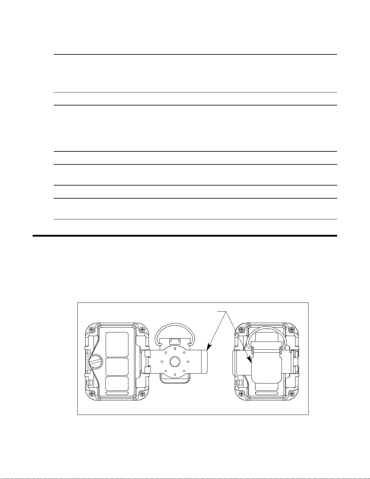
Chapter 2: Description
Battery Cover Screw
Battery Cover
AIR
SO2
LCD
Buzzer Openi ng
IrDA Port
Cont rol Buttons
W rist Strap
Connection
POW ER
MODE
Diffusion Port
Alarm LED
Figure 1: Component Location
Overview
This chapter describes the SC-04 instrument and its accessories.
Instrument Description
Case
The SC-04’s sturdy, high-impact plastic case is radio frequency (RF) resistant and is suitable for
use in many environmental conditions, indoors and out. The case is dust proof and water resistant.
A clear plastic window is located on the front of the case for viewing the LCD. The sensor
retainer is located on the right side of the case and allows access to the filters and sensor. A feature
in the lower left corner of the rear case is used to install the optional wrist strap.
LCD
A digital LCD (liquid crystal display) is visible through a clear plastic window in the top case.
The LCD shows the gas reading. The LCD also shows information for each of the SC-04’s
operating modes.
SC-0 4 Operator’s Manual Chapter 2: Description • 11
Find Quality Products Online at: sales@GlobalTestSupply.com
www.GlobalTestSupply.com
Page 12

Control Buttons
Two control buttons, AIR and POWER MODE, are located below the LCD.
Table 3: SC-04 Control Button Functions
Button Function(s)
AIR
POWER MODE
• turns on LCD backlight
• resets alarm condition if LATCH is set to ON in Maintenance Mode
• enters User Mode, Maintenance Mode, and Gas Select Mode when
used with POWER MODE
• activates the demand zero function (adjusts the SC-04’s fresh air
reading)
• changes the value of a parameter available for adjustment
• scrolls through parameter options
• turns the SC-04 on and off
• turns on LCD backlight
• enters and scrolls through Display Mode
• enters instructions into the SC-04’s microprocessor
• resets alarm condition if LATCH is set to ON in Maintenance Mode
• enters User Mode, Maintenance Mode, and Gas Select Mode when
used with AIR
Alarm LED
The alarm LED above the sensor and buzzer openings alerts you to gas, low battery, and failure
alarms.
Buzzer
One solid-state electronic buzzer is located inside the case. Sound exits the case through a hole in
the upper left corner of the front case. The buzzer sounds for gas alarms, malfunctions, and low
battery voltage. It also provides feedback for button presses and while in Display, User,
Maintenance, or Gas Select Mode.
Vibrator
A vibrating motor inside the SC-04 case vibrates for gas alarms and unit malfunctions.
NOTE: If STEALTH is set to ON, the vibrator only functions when VIB in the STEALTH Gas
Select Mode item is set to ON (see page 101).
12 • Chapter 2: Description SC- 04 Operator’s Manual
Find Quality Products Online at: sales@GlobalTestSupply.com
www.GlobalTestSupply.com
Page 13

Sensor
The sensor is an electrochemical cell that consists of two precious metal electrodes in a dilute acid
electrolyte. A gas permeable membrane covers the sensor face and allows gas to diffuse into the
electrolyte. The gas reacts in the sensor and produces a current proportional to the concentration
of the target gas. The SC-04’s circuitry amplifies the current, converts the current to a gas
concentration, and displays the concentration on the LCD.
Each target gas has its own sensor.
Filters
NO2 and SO2 Sensors’ H2S Removal Filter Disk (Tan)
An H2S removal filter disk is placed into a recess in the sensor gasket over the NO2 or SO2 sensor.
The filter disk prolongs the life of the sensors by preventing H2S in the ambient air from reaching
the sensor. The filter should be replaced every 6 months.
HCN Sensor H2S Removal Filter Disk (Dark Gray)
An H2S removal filter disk is placed into a recess in the sensor gasket over the HCN sensor. The
filter disk prolongs the life of the sensors by preventing H
sensor. The filter should be replaced every 6 months.
PH3 Sensor Humidity Filter (White)
S in the ambient air from reaching the
2
A white humidity filter is placed into a recess in the sensor gasket over the PH3 sensor. The filter
absorbs humidity in the sampling environment to prevent unstable readings around 0 ppm. The
filter should be replaced every 6 months.
NH3 Sensor’s Humidity Filter (White)
A white humidity filter is placed into a recess in the filter gasket over the NH3 sensor. The filter
absorbs humidity in the sampling environment to prevent unstable readings around 0 ppm. The
filter should be replaced every 6 months.
Hydrophobic Filter
The white, circular hydrophobic filter fits into a recessed area in the front case and is held in place
by the sensor gasket. It prevents water and particulates from entering the instrument.
Infrared Communications Port
An infrared (IR) communications port is located at the top of the instrument, near the LED.
Logged data transmits through the port in standard IrDA protocol. A computer’s infrared port or
an IrDA/USB cable connected to a USB port can be used to download data to the 04 Series
Datalogging Program. See the 04 Series Datalogging Program operator’s manual for data logging
and downloading instructions.
Batteries
2 AAA batteries (alkaline or Ni-MH) power the SC-04. At 25°C alkaline batteries will last at least
3,000 hours (125 days) and Ni-MH batteries will last at least 2,000 hours (83 days). The battery
icon in the upper right of the LCD shows remaining battery life.
SC-0 4 Operator’s Manual Chapter 2: Description • 13
Find Quality Products Online at: sales@GlobalTestSupply.com
www.GlobalTestSupply.com
Page 14
A low battery warning activates when the SC-04 detects a low battery voltage. The SC-04 sounds
Open
Alligator Clip
Closed
Figure 2: Alligator Clip
a dead battery alarm when battery voltage is too low for Measuring Mode.
WARNING: Use only Duracell MN2400 or PC2400 or Eneloop BK-4MCC batteries to
maintain the QPS classification of the SC-04. Use of other batteries will void the
QPS classification and may void the warranty. Do not mix old/new or different
types of batteries.
AVERTISSEMENT: Utiliser uniquement des piles Duracell MN 2400 ou PC 2400 ou
Eneloop BK-4MCC de maintenir la classification QPS de la SC-04.
L’utilisation d’autres piles annule la classification QPS et peut annuler
la garantie. Ne mélangez pas les anciennes/nouvelles ou différents types
de piles.
WARNING: To prevent ignition of a hazardous atmosphere, the batteries must only be
changed in an area known to be nonhazardous.
AVERTISSEMENT: Pour éviter l'inflammation d'une atmosphère dangereuse, la batterie ne
doit être remplacée que dans une zone non dangereuse.
Standard Accessories
Alligator Clip
An alligator clip installs to 2 spring bars on the rear case. Use the alligator clip to attach the SC-04
to clothing or a belt. Teeth in the alligator clip’s jaws prevent slipping. The alligator clip can be
rotated to change the instrument’s orientation.
14 • Chapter 2: Description SC- 04 Operator’s Manual
Find Quality Products Online at: sales@GlobalTestSupply.com
www.GlobalTestSupply.com
Page 15

Protective Rubber Boot
Side Front
Figure 3: Rubber Boot
Belt Clip
Figure 4: Belt Clip
A protective rubber boot is installed over the SC-04.
Optional Accessories
Belt Clip
The belt clip installs to 2 spring bars on the rear case and is used to easily clip the SC-04 onto a
belt.
Wrist Strap
The wrist strap connects to a feature on the back case.
SC-0 4 Operator’s Manual Chapter 2: Description • 15
Find Quality Products Online at: sales@GlobalTestSupply.com
www.GlobalTestSupply.com
Page 16

Calibration Cup
Figure 5: Calibration Cup
The calibration cup installs over the sensor. You must use the calibration cup when performing a
bump test, calibration, or gas test.
IrDA/USB Cable
Unless your computer has a built-in IrDA port, a IrDA/USB cable is needed to establish
communication between the SC-04 and the Datalogging Program or the Setup Program.
16 • Chapter 2: Description SC- 04 Operator’s Manual
Find Quality Products Online at: sales@GlobalTestSupply.com
www.GlobalTestSupply.com
Page 17

Chapter 3: Measuring Mode
5
SEC
RESUME
5
SEC
YES .MODE
5
SEC
NO .AIR
Overview
This chapter explains how to use the SC-04 to perform confined space entry monitoring or
general area monitoring in Measuring Mode.
Start Up
This section explains how to start up the SC-04, get it ready for operation, and turn it off.
Turning On the SC-04
To illustrate certain functions, the following description of the SC-04 start up sequence assumes
that the following items in User Mode are turned on: LUNCH, CAL.RMDR, and BP.RMDR in
User Mode, and ID DISP and A.ZERO in Maintenance Mode. If any of these items are turned
off, then the corresponding screens do not appear.
1. Press and briefly hold down POWER MODE. Release the button when you hear a beep.
2. If LUNCH is set to ON (factory setting if OFF, see page 65), the Lunch Break Screen
appears. The unit counts down from 5 seconds.
a. Continue Accumulating: To continue accumulating peak and time-weighted average
(TWA) readings from the last time the SC-04 was used, press and release POWER
MODE or allow the countdown to reach 0. The short-term exposure limit (STEL) reading
is reset each time the SC-04 is turned on.
b. Reset Accumulation: To reset the accumulation of peak and time-weighted average
(TWA) readings, press and release AIR before the countdown reaches 0.
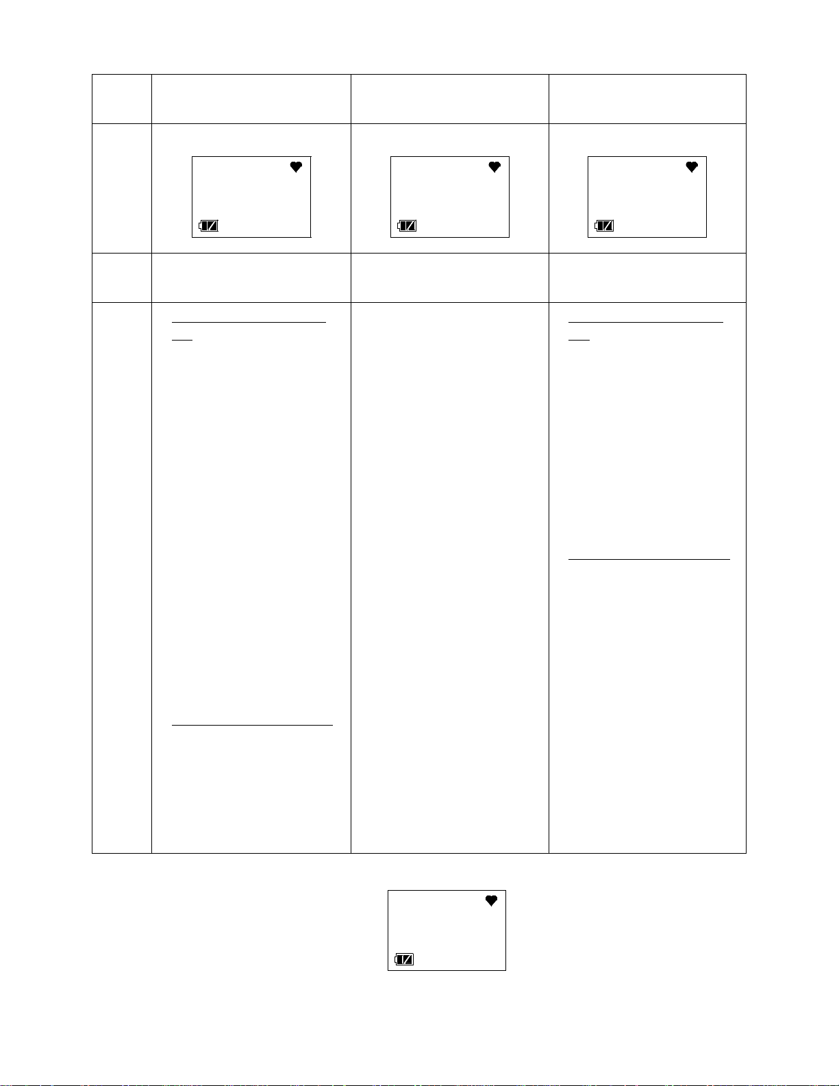
3. If CAL.RMDR is set to ON (factory setting) and a calibration is due, the screen that appears
next depends on how CAL.EXPD is set in User Mode (see page 58). The three possible
screens are described below. If a calibration is not due, the instrument displays the number of
days left until a calibration is due.
SC-0 4 Operator’s Manual Chapter 3: Measuring Mode • 17
Find Quality Products Online at: sales@GlobalTestSupply.com
www.GlobalTestSupply.com
Page 18

LCD
CAL
CAL - LMT
FAIL
CAL - LMT
0
d
NEXT .CAL
CAL.EXPD set to
CONFIRM (factory setting)
CAL.EXPD set to
CANT.USE
CAL.EXPD set to
NONE
Sound Buzzer sounds double pulsing
tone
Action
• Option A, Perform
calibration: Press and
release POWER MODE to
enter User Mode and
perform a calibration. The
instrument takes you
straight to the calibration
start screen in User Mode’s
GAS CAL\A-CAL(E-CAL)
item (if Password
Protection is set to On
using the 04 Series Setup
Program, you must enter a
password first). See page 46
for calibration instructions.
If the calibration is
successful, the screen above
will not appear again until
the unit is due for
calibration. If the calibration
is not successful, the screen
above will again appear in
the startup sequence.
• Option B, Bypass message
To continue without
performing a calibration,
press and release AIR.
Buzzer sounds double puls-
ing tone
The SC-04 cannot be used
until a successful calibration
is performed. Press and
release POWER MODE to
enter User Mode and perform
a calibration. The instrument
takes you straight to the cali-
bration start screen in User
Mode’s GAS CAL/A-CAL
(E-CAL) item (if Password
Protection is set to On using
the 04 Series Setup Program,
you must enter a password
first). If you don’t press
POWER MODE, the instru-
ment automatically goes to
the calibration start screen
after 6 seconds (if Password
Protection is set to On using
the 04 Series Setup Program,
you must enter a password
first). See page 46 for calibra-
tion instructions.
If the calibration is successful,
:
the screen above will not
appear again until the unit is
due for calibration. If the cali-
bration is not successful, the
screen above will again
appear in the startup
sequence.
None
• Option A, Perform
calibration: If you want to
enter User Mode and
perform a calibration, press
and release POWER
MODE. The instrument
takes you straight to the
calibration start screen in
User Mode’s GAS CAL/ACAL (E-CAL) item (if
Password Protection is set
to On using the 04 Series
Setup Program, you must
enter a password first).
• Option B, Bypass message
To continue without
performing a calibration,
wait a few seconds for the
instrument to continue with
its startup sequence.
:
4. If BP.RMDR is set to ON (factory setting is OFF) and a bump test is due, the screen that
appears next depends on how BP.EXPD is set in User Mode (see page 62). The three possible
screens are described below. If a bump test is not due, the instrument displays the number of
days left until a bump test is due.
18 • Chapter 3: Measuring Mode SC-04 Operator’s Manual
Find Quality Products Online at: sales@GlobalTestSupply.com
www.GlobalTestSupply.com
Page 19
LCD
CAL
BP - LMT
FAIL
BP - LMT
0
d
NEXT .BP
2020
4.21
10:40
BP.EXPD set to
CONFIRM (factory setting)
BP.EXPD set to
CANT.USE
BP.EXPD set to
NONE
Sound Buzzer sounds double pulsing
tone
Actio
n
• Option A, Perform bump
test: Press and release
POWER MODE to enter
User Mode and perform a
bump test. The instrument
takes you straight to the
bump test start screen in
User Mode’s BUMP item (if
Password Protection is set
to On using the 04 Series
Setup Program, you must
enter a password first). See
page 42 for bump test
instructions.
If the bump test is
successful, the screen above
will not appear again until
the unit is due for bump
testing. If the bump test is
not successful, the screen
above will again appear in
the startup sequence.
• Option B, Bypass message
To continue without
performing a bump test,
press and release AIR.
Buzzer sounds double puls-
ing tone
The SC-04 cannot be used
until a successful bump test
is performed. Press and
release POWER MODE to
enter User Mode and perform
a bump test. The instrument
takes you straight to the
bump test start screen in User
Mode’s BUMP item (if Pass-
word Protection is set to On
using the 04 Series Setup
Program, you must enter a
password first). If you don’t
press POWER MODE, the
instrument automatically
goes to the bump test start
screen after 6 seconds (if
Password Protection is set to
On using the 04 Series Setup
Program, you must enter a
password first). See page 42
for bump test instructions.
If the bump test is successful,
:
the screen above will not
appear again until the unit is
due for bump testing. If the
bump test is not successful,
the screen above will again
appear in the startup
sequence.
None
• Option A, Perform bump
test: If you want to enter
User Mode and perform a
bump test, press and release
POWER MODE. The
instrument takes you
straight to the bump test
start screen in User Mode’s
BUMP item (if Password
Protection is set to On
using the 04 Series Setup
Program, you must enter a
password first).
• Option B, Bypass message
To continue without
performing a bump test,
wait a few seconds for the
instrument to continue with
its startup sequence.
:
5. The Date/Time Screen appears for a few seconds.
Find Quality Products Online at: sales@GlobalTestSupply.com
SC-0 4 Operator’s Manual Chapter 3: Measuring Mode • 19
www.GlobalTestSupply.com
Page 20

6. The Battery Voltage Screen appears for a few seconds. An “AL-L” at the bottom of the screen
batt
2.8
AL -L
v
SO2
100.00
F . S .
ppm
SO2
2.00
WARNING
ppm
SO2
ppm
SO2
5.00
ALARM
ppm
SO2
100.00
ALARM H
ppm
SO2
5.00
STEL
ppm
SO2
2.00
TWA
ppm
USER
ID
U_ID_001
STN
ID
S_ID_001
SO2
FAIL
SENSOR
ppm
indicates that the alarms are set to latching. An “AL-A” at the bottom of the screen indicates
that the alarms are set to auto reset. See page 92 for a description of how to change this
parameter.
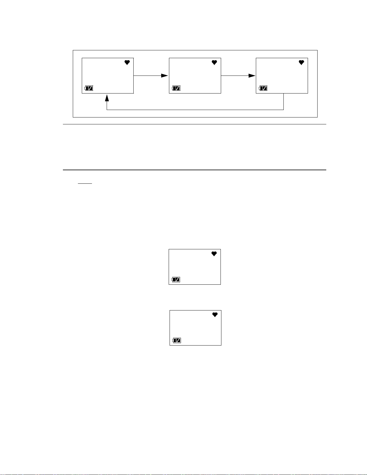
7. The following screens display for 1 second each: Gas Name, Full Scale, Warning Setpoint,
Alarm Setpoint, Alarm H Setpoint, STEL Setpoint, and TWA Setpoint.
8. If ID DISP is set to ON (factory setting is OFF, see page 93), the User ID Screen appears for
a few seconds, followed by the Station ID Screen.
9. If the SC-04 experiences a sensor failure during start up, a screen indicating that the sensor
failed appears and the buzzer sounds a double pulsing tone once per second.
You cannot acknowledge the failure and continue to Measuring Mode. Replace the failed
sensor as soon as possible.
20 • Chapter 3: Measuring Mode SC-04 Operator’s Manual
Find Quality Products Online at: sales@GlobalTestSupply.com
www.GlobalTestSupply.com
Page 21
10. If A.ZERO is set to ON (factory setting is OFF, see page 93), the instrument prompts you to
A .ZERO
YES .MODE
NO .AIR
0000
PASS- W
SO2
0
ppm
do an auto zero. An auto zero operation sets the reading to 0 ppm.
WARNING: Make sure that the instrument is in a known fresh air environment (an
environment free of combustible or toxic gases and of normal oxygen
content, 20.9%) before performing an auto zero operation. If you perform an
auto zero operation in an area with gases present, the adjustment will not be
accurate.
You must
you do not press any key, after 15 seconds, the instrument enters Measuring Mode without
performing an auto zero.
If Password Protection is turned On (factory setting is Off) using the 04 Series Setup
Program, a user-set password is required to perform an auto zero. When the password
screen appears, adjust each digit with the AIR button and press and release the POWER
MODE button to move on to the next digit. Once the password is entered, the instrument
performs the auto zero.
11. The SC-04 is now monitoring for gas in Measuring Mode. The Measuring Mode Screen
displays the current gas reading.
press and release the POWER MODE button to perform an auto zero function. If
SC-0 4 Operator’s Manual Chapter 3: Measuring Mode • 21
Find Quality Products Online at: sales@GlobalTestSupply.com
www.GlobalTestSupply.com
Page 22
Performing a Demand Zero
0000
PASS- W
0000
PASS- W
Perform a demand zero before using the SC-04. This sets the reading to 0 ppm.
1. Find a fresh-air environment. This is an environment free of toxic or combustible gases and of
normal oxygen content (20.9%).
2. Turn on the unit as described above in Turning On the SC-04.
3. Press and hold AIR. The buzzer pulses and the LCD prompts you to continue holding AIR (if
KEY.TONE is set to ON in User Mode).
4. Continue to hold AIR until the LCD prompts you to release it. The SC-04 sets the fresh air
reading. Start up is complete and the unit is now ready for monitoring.
5. If Password Protection is turned On (factory setting is Off) using the 04 Series Setup
Program, a user-set password is required to perform a demand zero. When the password
screen appears, adjust each digit with the AIR button and press and release the POWER
MODE button to move on to the next digit. Once the password is entered, the instrument sets
the fresh air reading.
Turning Off the SC-04
1. Press and hold POWER MODE.
2. OFF appears on the display and the buzzer pulses for about five seconds (if KEY.TONE is set
to ON in User Mode).
3. Release the button when OFF disappears from the display.
4. If Password Protection is turned On (factory setting is Off) using the 04 Series Setup
Program, a user-set password is required to turn off the SC-04. When the password screen
appears, adjust each digit with the AIR button and press and release the POWER MODE
button to move on to the next digit. Once the password is entered, the instrument shuts off.
22 • Chapter 3: Measuring Mode SC-04 Operator’s Manual
Find Quality Products Online at: sales@GlobalTestSupply.com
www.GlobalTestSupply.com
Page 23
Measuring Mode Operation
SO2
0.00
S.
ppm
SO2
0.00
ppm
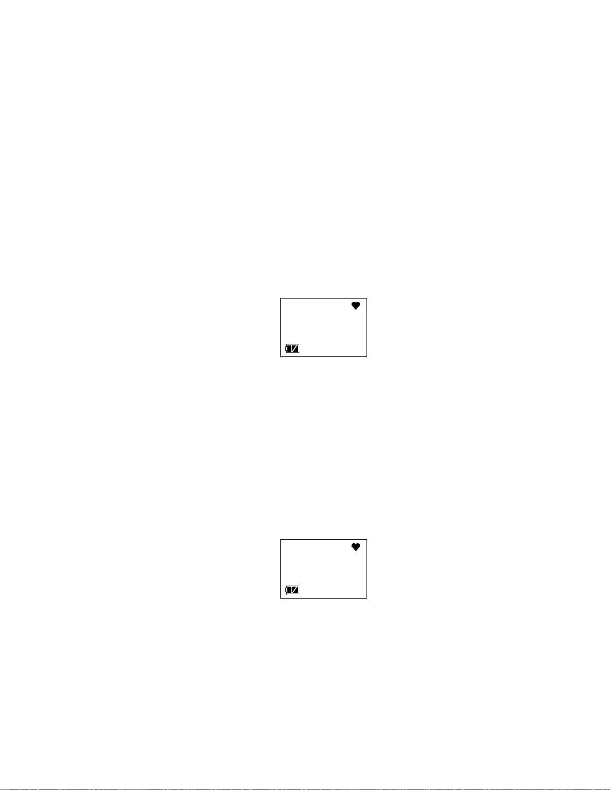
When the SC-04 completes its startup sequence, it is in Measuring Mode. In Measuring Mode the
SC-04 continuously monitors the sampled atmosphere and displays the gas concentration. The
SC-04 is in Normal Operation if there are no alarm indications.
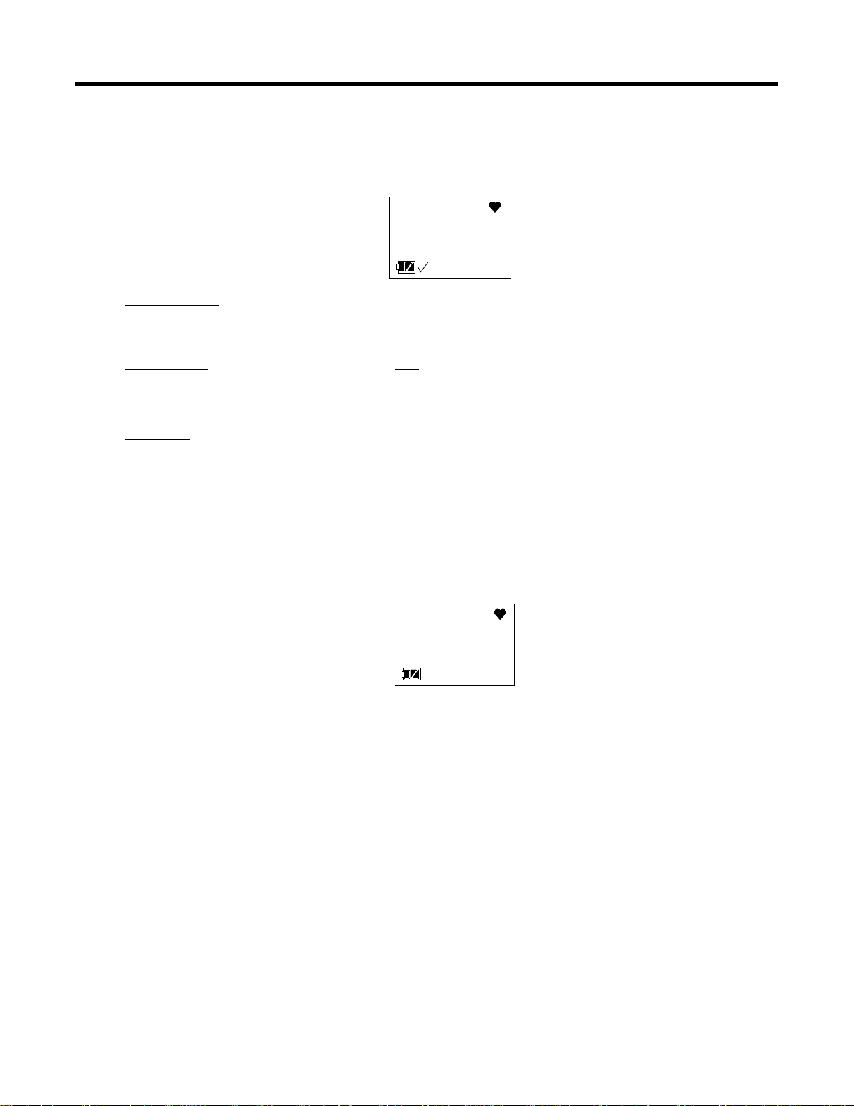
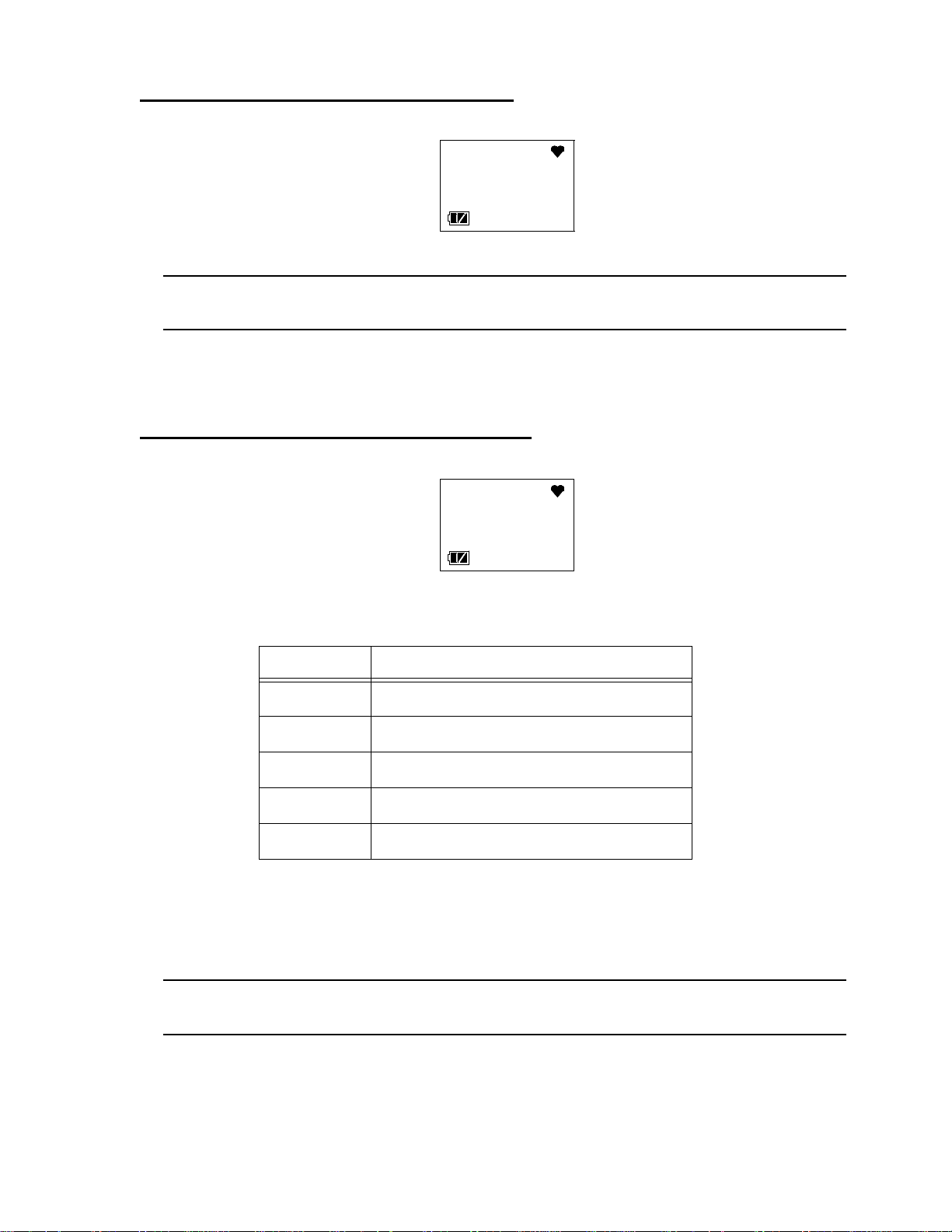
Heart Symbol: The heart symbol in the top right corner of the LCD indicates the operation status
and flashes when normal. A microprocessor error causes the heart symbol to stop flashing or to
disappear.
Check Mark: If BP.RMDR is set to ON and if a bump test is not due, a check mark appears in the
lower left corner of the LCD.
“S”: If the instrument is operating in Stealth Mode, an “S.” appears at the bottom of the LCD.
Backlight: In a low-light environment, press and release either button to turn on the display
backlight. See page 67 to program backlight duration.
Confirmation/Non-Compliance Indicator: If the BEEP item in User Mode is set to anything other
than OFF, the SC-04 gives periodic indications to confirm that it’s operating or to indicate a noncompliance (see page 66).
Monitoring an Area
1. Start up the SC-04 as described above in “Start Up” on page 17. It is now in Measuring Mode.
2. The instrument displays the gas reading.
3. Take the SC-04 to the monitoring area.
4. Wait at least 15 seconds.
5. If a reading is observed, allow the reading to stabilize to determine the gas concentration
present.
6. If a gas alarm occurs, take appropriate action. See page 26.
Interference Information
Some gases interfere with the super toxic sensors. For a complete list of these gases, see page 102.
SC-0 4 Operator’s Manual Chapter 3: Measuring Mode • 23
Find Quality Products Online at: sales@GlobalTestSupply.com
www.GlobalTestSupply.com
Page 24

Alarms
This section covers alarm indications in Measuring Mode. It also describes how to reset the SC-04
after an alarm occurs and how to respond to an alarm condition.
NOTE: False alarms may be caused by radio frequency (RF) or electromagnetic (EMI)
Alarm Indications
The SC-04 buzzer sounds an alarm, the LED flashes, and the vibrator pulses when any sort of
alarm condition or failure occurs. If the SC-04 is operating in Stealth Mode, the buzzer does not
sound and the vibrator’s operation depends on the VIB setting in Gas Select Mode’s STEALTH
item. See page 101 for more information.
NOTE: If an alarm condition occurs while you are in Display Mode, the SC-04 automatically
The table below summarizes the types of alarms produced by the SC-04 and their indications.
interference. Keep the SC-04 away from RF and EMI sources such as radio transmitters
or large motors.
returns to the Measuring Mode screen.
Table 4: Alarm Types and Indications
Alarm Type Visual Indications Other Indications
War ning
Concentration of gas rises above
the Warning setting.
Alarm
Concentration of gas rises above
the Alarm setting.
Alarm H
Concentration of gas rises above
the Alarm H setting.
• Gas reading flashes
• WARNING appears at the bottom
of the LCD
• Alarm LED flashes once per
second
• Backlight turns on
• Gas reading flashes
• ALARM appears at the bottom of
the LCD
• Alarm LED flashes twice per
second
• Backlight turns on
• Gas reading flashes
• ALARM H appears at the bottom
of the LCD
• Alarm LED flashes twice per
second
• High-low tone sounds
once per second
• Vibrator pulses once per
second
• High-low tone sounds
twice per second
• Vibrator pulses twice
per second
• High-low tone sounds
twice per second
• Vibrator pulses twice
per second
• Backlight turns on
24 • Chapter 3: Measuring Mode SC-04 Operator’s Manual
Find Quality Products Online at: sales@GlobalTestSupply.com
www.GlobalTestSupply.com
Page 25

Table 4: Alarm Types and Indications
Alarm Type Visual Indications Other Indications
TWA or STEL
Concentration rises above the
TWA or STEL alarm setting.
Over Range
Minus Over Range
• Gas reading flashes
• TWA or STEL appears at the
bottom of the LCD
• Alarm LED flashes once per
second
• Backlight turns on
• Gas reading is replaced with a
flashing
• Gas name and units flash
• OVER appears at the bottom of
the LCD
• Alarm LED flashes twice per
second
• Backlight turns on
• Affected channel’s gas reading is
replaced with a flashing “
• Gas name and units flash
• M OVER appears at the bottom of
the LCD
- - - -”
• High-low tone sounds
once per second
• Vibrator pulses once per
second
• High-low tone sounds
twice per second
• Vibrator pulses twice
per second
• High-low tone sounds
twice per second
• Vibrator pulses twice
per second
Low Battery Warning
Dead Battery Alarm
Sensor Failure
Clock Failure
• Alarm LED flashes twice per
second
• Backlight turns on
• The last bar in the battery icon
starts flashing
• Gas reading disappears. FAIL
BATTERY appears on the LCD.
• Alarm LED flashes once per
second
• FAI L S ENSOR appears on the
LCD.
• Alarm LED flashes once per
second
• FAIL 050 CLOCK appears on the
LCD
• Alarm LED flashes once per
second
None
Double pulsing tone
sounds once per second
Double pulsing tone
sounds once per second
Double pulsing tone
sounds once per second
SC-0 4 Operator’s Manual Chapter 3: Measuring Mode • 25
Find Quality Products Online at: sales@GlobalTestSupply.com
www.GlobalTestSupply.com
Page 26

Table 4: Alarm Types and Indications
0000
PASS- W
Alarm Type Visual Indications Other Indications
System Failure
• FAIL SYSTEM and an error code
appear on the LCD
• Alarm LED flashes once per
second
Double pulsing tone
sounds once per second
Responding to Alarms
This section describes response to gas, over range, battery, sensor failure, clock failure, and
system failure alarms.
Responding to Gas Alarms
1. Follow your established procedure for an increasing gas condition.
2. Reset the alarm as necessary or allowed.
a. If LATCH is set to ON (factory setting) in Maintenance Mode, the gas reading must fall
below an alarm setting before you can reset the alarm condition using POWER MODE or
AIR.
If Password Protection is turned On (factory setting is Off) using the 04 Series Setup
Program, you must press POWER MODE and AIR at the same time and then enter a
user-set password to reset an alarm condition. When the password screen appears, adjust
each digit with the AIR button and press and release the POWER MODE button to move
on to the next digit. Once the password is entered, the alarm condition resets.
b. If LATCH is set to OFF in Maintenance Mode, the alarm condition automatically resets
when gas reading falls below an alarm setpoint.
Responding to Over Range Alarms
WARNING: An over range condition may indicate an extreme carbon monoxide
concentration or an explosive concentration. Confirm the gas concentration with
a different SC-04 or with another gas detecting device.
AVERTISSEMENT: Un dépassement de la plage peut indiquer une concentration extrême en
monoxyde de carbone ou une concentration en explosif. Confirmez la
concentration de gaz avec un SC-04 différent ou avec un autre dispositif
de détection de gaz.
1. Follow your established procedure for an extreme gas condition.
26 • Chapter 3: Measuring Mode SC-04 Operator’s Manual
Find Quality Products Online at: sales@GlobalTestSupply.com
www.GlobalTestSupply.com
Page 27

2. Reset the alarm using POWER MODE or AIR once the alarm condition clears if LATCH is
0000
PASS- W
set to ON (factory setting) in Maintenance Mode.
If Password Protection is turned On (factory setting is Off) using the 04 Series Setup
Program, you must press POWER MODE and AIR at the same time and then enter a userset password to reset an alarm condition. When the password screen appears, adjust each
digit with the AIR button and press and release the POWER MODE button to move on to
the next digit. Once the password is entered, the alarm condition resets.
3. Calibrate the SC-04 as described on page 46.
4. If the over range condition continues or if you are not able to successfully calibrate the unit,
you may need to replace the sensor.
5. If the over range condition continues after you replace the sensor, contact RKI Instruments,
Inc. for further instructions.
Responding to Battery Alarms
WARNING: The SC-04 is not operational as a gas monitoring device during a dead battery
alarm. Take the SC-04 to a non-hazardous area and replace the batteries as
described in “Replacing the Batteries (Alkaline or Ni-MH)” on page 74.
The SC-04 is fully functional during a low battery warning. However, only a couple of days of
operating time remain. The amount of time depends on LCD backlight use and alarm frequency.
Replace the batteries as described on page 74 as soon as possible.
NOTE: Alarms and the LCD backlight consume battery power and reduce the amount of
operating time remaining.
Responding to Sensor Failure Alarms
1. Calibrate the sensor as described on page 46.
2. If the sensor failure continues, replace the sensor as described on page 81.
3. If the sensor failure condition continues after replacing the sensor, contact RKI Instruments,
Inc. for further instructions.
SC-0 4 Operator’s Manual Chapter 3: Measuring Mode • 27
Find Quality Products Online at: sales@GlobalTestSupply.com
www.GlobalTestSupply.com
Page 28
Responding to Clock Failure Alarms
FAIL
050
CLOCK
FAIL
031
SYSTEM
A clock failure alarm occurs if the unit’s internal clock malfunctions.
1. Press and release POWER MODE to continue into Measuring Mode.
CAUTION: There is no datalogging function if you operate the instrument after a
clock failure.
2. Attempt to set the date using the DATE item in User Mode (see page 70).
3. If the date cannot be set correctly, contact RKI Instruments, Inc. as soon as possible.
Responding to System Failure Alarms
1. If a system failure occurs, the system failure screen displays an error code as shown below.
2. The error code meanings are shown in the table below:
Table 5: Error Code Explanation
Error Code Explanation
000 ROM failure
010 RAM failure
020 FRAM failure
031 FLASH memory failure
082 Temperature sensor failure
3. If the error code is anything but 031, the instrument cannot be used. Contact RKI Instruments,
Inc. as soon as possible.
If the error code is 031, press and release POWER MODE to continue into Measuring
Mode if the instrument must be used temporarily.
CAUTION: There is no datalogging function if you operate the instrument after a
031 system failure. Contact RKI Instruments, Inc. as soon as possible.
28 • Chapter 3: Measuring Mode SC-04 Operator’s Manual
Find Quality Products Online at: sales@GlobalTestSupply.com
www.GlobalTestSupply.com
Page 29

Data Logging
The SC-04 logs Measuring Mode gas readings, alarm data, and calibration data to its internal
memory. Logged data can be download it to a computer via the infrared communications port on
the front of the unit.
The data logging capacity depends on how often the SC-04 stores data and how often the
SC-04 is turned on and off. The table below illustrates how much data logging time is available
for the various interval times. It assumes that the unit is only turned on once and there are no
alarms. The data logging interval time must be set using the 04 Series Datalogging Program.
Table 6: Data Logging Capacity
Interval
Time
10 seconds 10 hours
20 seconds 20 hours
30 seconds 30 hours
1 minute 60 hours
3 minutes 180 hours
5 minutes 300 hours
10 minutes 600 hours
Data Logging
Capacity
To utilize the SC-04’s downloading capability, you need:
• PC with Windows 7, Windows 8, Windows 10, or Windows 11
• IrDA port or IrDA/USB cable (cable available from RKI Instruments, Inc.)
• 04 Series Datalogging Program (available at www.rkiinstruments.com/04series).
For a complete description of the Datalogging Program and procedures for downloading data to a
computer, see the 04 Series Datalogging Program Operator’s Manual.
SC-0 4 Operator’s Manual Chapter 3: Measuring Mode • 29
Find Quality Products Online at: sales@GlobalTestSupply.com
www.GlobalTestSupply.com
Page 30

Chapter 4: Display Mode
This section describes Display Mode which is accessible from Measuring Mode. See Table 7
below for a list of Display Mode’s menu items, a short description of each item, and the page
number for further description.
Table 7: Display Mode Menu Items
Display Mode
Menu Item
PEAK (page 31) Displays the Peak reading.
STEL (page 32) Displays the STEL reading.
TWA (page 32) Displays the TWA reading.
USER ID (page 32)
STN ID (page 33)
CAL.DATA (page
B
34)
BP.DATA (page 34)
DATE (page 35) Displays the current date and time.
TEMP (page 35) Displays the current temperature.
ALARM--P (page
35)
Description
A
View and/or change the User ID.
A
View and/or change the Station ID.
Displays the last calibration date.
C
Displays the last bump test date.
View alarm points.
BUZZ.VOL
(page 36)
A
Only appears if DISP.SET is set to ON in User Mode (factory setting) and if ID DISP is set to ON in
Maintenance Mode (factory setting is OFF).
B
Only appears if CAL.RMDR is set to ON in User Mode (factory setting).
C
Only appears if BP.RMDR is set to ON in User Mode (factory setting is OFF).
D
Only appears if DISP.SET is set to ON in User Mode (factory setting).
D
Set the buzzer volume to LO or HI (factory setting).
Tips for Using Display Mode
• To enter Display Mode and scroll from one item to the next or skip an item when a question is
asked, press and release POWER MODE.
• To enter an item, press and release AIR.
30 • Chapter 4: Display Mode SC- 04 Operator’s Manual
Find Quality Products Online at: sales@GlobalTestSupply.com
www.GlobalTestSupply.com
Page 31

• To change a flashing parameter, press and release AIR. To reverse the movement in a list (ie.
SO2
20.00
PEAK
ppm
CLR
HOLD
CLR
RELEASE
from down to up or vice versa):
a. Press and hold AIR.
b. Immediately press POWER MODE and then release both buttons.
• To exit from an entered-information screen and go back to Measuring Mode, press and release
POWER MODE until you get to the Measuring Mode screen.
NOTE: Each screen displays for 20 seconds. If you do not press a button within 20 seconds, the
SC-04 automatically returns to Measuring Mode.
Peak Screen (PEAK)
The peak screen displays the highest concentration detected since the SC-04 was turned on. The
peak reading is stored until a higher level is detected, the peak reading is cleared, or the SC-04 is
turned off.
The lunch break feature enables the SC-04 to save the peak reading when it is turned off so it can
continue with the same peak when it is turned on again (see page 17).
To clear the peak reading, do the following:
NOTE: If Password Protection is set to On using the 04 Series Setup Program, the peak
reading cannot be cleared.
1. After entering Display Mode, press and release POWER MODE until PEAK appears.
2. Press and hold AIR until the screen prompts you to release it.
3. The peak reading is reset and the unit returns to the Peak Screen.
If you do not want to clear the peak reading, release AIR before the above screen sequence
occurs. The unit returns to the Peak Screen.
SC-0 4 Operator’s Manual Chapter 4: Display Mode • 31
Find Quality Products Online at: sales@GlobalTestSupply.com
www.GlobalTestSupply.com
Page 32

STEL Screen (STEL)
SO2
10.00
STEL
ppm
SO2
5.00
TWA
ppm
USER
ID
U_ID_001
USER
ID
CHG / AIR
USER
ID
NO /MODE
The STEL Screen displays the short term exposure limit (STEL) reading. The STEL reading is the
average reading over the last 15 minutes.
TWA Screen (TWA)
The TWA Screen displays the time weighted average (TWA) reading.
The TWA reading is the average reading over the last 8 hours. If 8 hours have not elapsed since
the last time the TWA reading was cleared, the average is still calculated over 8 hours. The
missing readings are assigned a value of 0. If LUNCH is set to OFF (factory setting), the TWA is
cleared when the SC-04 is turned off.
If LUNCH is set to ON, the SC-04 remembers the TWA reading when it is turned off and can
continue accumulation when it is turned on again (see page 17).
Changing the User ID (USER ID)
This screen only appears if DISP.SET in User Mode is set to ON (factory setting) and if ID DISP
in Maintenance Mode is set to ON (factory setting is OFF).
Use this screen to select a user ID from the 128 user IDs that are stored in the SC-04’s memory.
Before a user ID is selected on a brand new instrument, the user ID is “----------”. The factoryinstalled user IDs have a “U_ID_XXX” format.
The user ID provides a way to identify the SC-04 user during a data logging session.
User IDs can only be selected
the 04 Series Datalogging Program or 04 Series Setup Program.
1. After entering Display Mode, press and release POWER MODE until the USER ID screen
sequence appears.
in this menu item. In order to edit the 128 user IDs, you must use
32 • Chapter 4: Display Mode SC- 04 Operator’s Manual
Find Quality Products Online at: sales@GlobalTestSupply.com
www.GlobalTestSupply.com
Page 33

2. To change the User ID, press and release AIR. The current User ID flashes.
USER
ID
U_ID_001
STN
ID
S_ID_001
STN
ID
CHG / AIR
STN
ID
NO /MODE
STN
ID
S_ID_001
3. Use AIR to scroll to the desired User ID.
4. Press and release POWER MODE to save the User ID and return to the USER ID screen in
Display Mode.
Changing the Station ID (STN ID)
This screen only appears if DISP.SET in User Mode is set to ON (factory setting) and if ID DISP
in Maintenance Mode is set to ON (factory setting is OFF).
Use this screen to select a station ID from the 128 station IDs that are stored in the SC-04’s
memory. Before a station ID is selected on a brand new instrument, the station ID is
“----------”. The factory-installed station IDs have a “S_ID_XXX” format.
The station ID provides a way to identify the SC-04 location during a data logging session.
User IDs can only be selected in this menu item. In order to edit the 128 user IDs, you must use
the 04 Series Datalogging Program or 04 Series Setup Program.
1. After entering Display Mode, press and release POWER MODE until the STN ID screen
sequence appears.
2. To change the Station ID, press and release AIR. The current Station ID flashes.
3. Use AIR to scroll to the desired Station ID.
4. Press and release POWER MODE to save the Station ID and return to the STN ID screen in
Display Mode.
SC-0 4 Operator’s Manual Chapter 4: Display Mode • 33
Find Quality Products Online at: sales@GlobalTestSupply.com
www.GlobalTestSupply.com
Page 34

Last Successful Calibration Date (CAL.DATA)
DISP
CAL .DATA
DISP
YES / AIR
DISP
NO /MODE
2019
10.24
CAL .DATA
DISP
BP .DATA
DISP
YES / AIR
DISP
NO /MODE
2019
10.24
BP .DATA
The CAL.DATA screen shows the date of the last successful calibration. This screen only appears
if CAL.RMDR is set to ON (factory setting).
1. After entering Display Mode, press and release POWER MODE until the CAL.DATA screen
sequence appears.
2. Press AIR to enter the CAL.DATA screen. The date of the last successful calibration displays.
3. Press and release POWER MODE to return to the CAL.DATA screen in Display Mode.
Last Successful Bump Test Date (BP.DATA)
The BP.DATA screen shows the date of the last successful bump test. This screen only appears if
BP.RMDR is set to ON (factory setting is OFF).
1. After entering Display Mode, press and release POWER MODE until the BP.DATA screen
sequence appears.
2. Press AIR to enter the BP.DATA screen. The date of the last successful bump test displays.
34 • Chapter 4: Display Mode SC- 04 Operator’s Manual
Find Quality Products Online at: sales@GlobalTestSupply.com
3. When you are done viewing the last bump test date, press and release POWER MODE to
return to the BP.DATA screen in Display Mode.
www.GlobalTestSupply.com
Page 35

Date/Time Screen (DATE)
2020
4.21
10:40
25C
TEMP
DISP
ALARM-P
DISP
YES / AIR
DISP
NO /MODE
The DATE screen shows the instrument’s date and time.
Temperature Screen (TEMP)
The TEMP screen shows the surrounding area’s temperature.
Alarm Points Screen (ALARM--P)
The Alarm Points Screen shows the gas alarm settings.
1. After entering Display Mode, press and release POWER MODE until the ALARM--P screen
sequence appears.
2. Press and release AIR. The Full Scale Setting screen appears.
SC-0 4 Operator’s Manual Chapter 4: Display Mode • 35
Find Quality Products Online at: sales@GlobalTestSupply.com
www.GlobalTestSupply.com
Page 36
3. Use AIR to scroll through the Warning, Alarm, Alarm H, STEL, and TWA settings.
SO2
100.00
F. S.
ppm
SO2
2.00
WARNING
ppm
SO2
5.00
ALARM
ppm
SO2
100.00
ALARM H
ppm
SO2
5.00
STEL
ppm
SO2
2.00
TWA
ppm
AIR AIR
AIR AIR
AIR
HI
BUZZ .VOL
HI
CHG / AIR
HI
NO / MODE
4. While viewing the alarm settings for a particular alarm point, press and release AIR and
POWER MODE at the same time to simulate the alarm conditions. The buzzer will sound, the
LED will flash, and the instrument will vibrate just as it would if the displayed condition was
actually happening.
5. Press and release POWER MODE to return to the Alarm Points Screen.
Adjusting the Buzzer Volume (BUZZ.VOL)
The BUZZ.VOL screen allows you to adjust the volume of the instrument’s buzzer. This screen
only appears if DISP.SET in User Mode is set to ON (factory setting).
HI (factory setting): Buzzer volume is high.
LO: Buzzer volume is low.
1. While in Display Mode, press and release POWER MODE until BUZZ.VOL appears. The
current setting displays on the top line.
2. Press and release AIR. The current setting flashes.
3. Use AIR to display the desired setting.
4. Press and release POWER MODE to save the setting and return to the BUZZ.VOL item in
Display Mode.
36 • Chapter 4: Display Mode SC- 04 Operator’s Manual
Find Quality Products Online at: sales@GlobalTestSupply.com
www.GlobalTestSupply.com
Page 37

Chapter 5: User Mode and Calibration
Overview
This section describes the SC-04 in User Mode. See Table 8 below for a list of the items found in
User Mode, the page that the item’s instructions can be found on, and a short description of the
item.
Table 8: User Mode Menu Items
User Mode
Menu Item
BUMP (page 42) Perform a bump test.
GAS CAL (page 46) Perform a fresh air adjustment, perform a span adjustment, change the calibration gas
Description
BUMP Perform a bump test.
START Begin the warmup sequence and enter Measuring Mode.
ESCAPE Return to the BUMP menu item.
concentration.
AIR (page 46) Perform a fresh air adjustment.
A-CAL (page
47) or E-CAL
(page 51)
depending on ECAL User
Mode setting
A-CAL (or
E-CAL)
START Begin the warmup sequence and enter Measuring
CAL-P Set the calibration gas concentration.
ESCAPE Return to the A-CAL item in the GAS CAL menu.
Perform a span adjustment.
Mode.
ESCAPE Return to the GAS CAL item in User Mode.
SC-0 4 Operator’s Manual Chapter 5: User Mode and Calibration • 37
Find Quality Products Online at: sales@GlobalTestSupply.com
www.GlobalTestSupply.com
Page 38
Table 8: User Mode Menu Items
User Mode
Menu Item
CAL SET (page 57) Change parameters related to calibration.
Description
CAL.RMDR
(page 57)
CAL.INT (page
57)
CAL.EXPD
(page 58)
ON (factory setting)
when a calibration is due. Notification type depends on
CAL.EXPD setting below. CAL.DATA screen appears in Display
Mode.
OFF
: No notification upon startup when a calibration is due.
CAL.DATA screen does not appear in Display Mode.
How often the instrument needs to be calibrated.
Options: 1 - 1000 days (factory setting is 90 days)
Defines what action must be taken if a calibration is due upon
startup.
CONFIRM (factory setting)
edge that calibration is due and continue to Measuring Mode.
CANT.USE
bration is performed.
NONE
sequence continues.
: Cannot enter Measuring Mode until a successful cali-
: A screen indicates that calibration is due but warmup
: The instrument notifies the user upon startup
: Press and release AIR to acknowl-
BUMP.SET
(page 59)
ESCAPE Return to the CAL SET item in User Mode.
Change parameters related to bump testing.
SETTING (page
59)
GAS.TIME How long gas is applied during a bump test.
Choices: 30 (factory setting), 45, 60, 90 seconds
CHECK Percentage of calibration gas concentration that
the bump test reading must be within in order to
pass bump.
Options: 10%, 20%, 30%, 40%, 50% (factory set-
ting)
CAL.TIME How long gas is applied during a calibration.
GAS.TIME is deducted from this time.
Options: 90 (factory setting) or 120 seconds
A-CAL ON (factory setting)
tion automatically starts.
OFF
: If a bump test fails, a calibration does not
automatically start.
ESCAPE Return to the SETTING item in the BUMP SET
menu.
: If a bump test fails, a calibra-
38 • Chapter 5: User Mode and Calibration SC-04 Operator’s Manual
Find Quality Products Online at: sales@GlobalTestSupply.com
www.GlobalTestSupply.com
Page 39

Table 8: User Mode Menu Items
User Mode
Menu Item
BUMP.SET (page 59)
cont.
Description
BP.RMDR
(page 61)
BP.INT (page
62)
BP.EXPD (page
62)
ESCAPE Return to the BUMP SET item in User Mode.
ON: The instrument notifies the user upon startup when a bump
test is due. Notification type depends on BP.EXPD setting below.
BP.DATA screen appears in Display Mode.
OFF (factory setting)
test is due. BP.DATA screen does not appear in Display Mode.
How often the instrument needs to be bump tested.
Options: 0 - 30 days (factory setting is 30 days)
Defines what action must be taken if a bump test is due upon
startup.
CONFIRM (factory setting)
edge that bump test is due and continue to Measuring Mode.
CANT.USE
bump test is performed.
NONE
sequence continues.
: Cannot enter Measuring Mode until a successful
: A screen indicates that bump test is due but warmup
: No notification upon startup when a bump
: Press and release AIR to acknowl-
ALARM-P (page 63) Set alarm points (WARNING, ALARM, ALARM H, STEL, TWA) and/or reset all
alarms to their default settings.
LUNCH (page 65) ON
BEEP (page 66) Set confirmation beep parameters.
: Lunch break feature is on. Instrument asks if you want to resume TWA and PEAK
readings at startup.
OFF (factory setting)
readings every time it’s turned on.
BEEP.SEL
(page 66)
: Lunch break feature is off. Instrument resets TWA and PEAK
: LED flashes and instrument vibrates based on interval
LED
defined in BEEP.INT to confirm instrument is still operating.
BUZZER
val defined in BEEP.INT to confirm instrument is still operating.
LED+BUZ
based on interval defined in BEEP.INT to confirm instrument is
still operating.
BMP/CAL
bump test or calibration is due regardless of whether BP.RMDR
and/or CAL.RMDR are set to ON.
OFF (factory setting)
ating or that a bump test or calibration is due.
: Buzzer sounds and instrument vibrates based on inter-
: LED flashes, buzzer sounds, and instrument vibrates
: LED flashes based on interval defined in BEEP.INT if
: No alerts to confirm instrument is still oper-
SC-0 4 Operator’s Manual Chapter 5: User Mode and Calibration • 39
Find Quality Products Online at: sales@GlobalTestSupply.com
www.GlobalTestSupply.com
Page 40

Table 8: User Mode Menu Items
User Mode
Menu Item
BEEP (page 66)
cont.
Description
BEEP.INT
(page 67)
Confirmation alert interval. Confirmation type defined in
BEEP.SEL.
Options: 0.5 minute and 1 to 99 minutes in 1 minute increments.
The factory setting is 5 minutes.
ESCAPE Return to the BEEP item in User Mode.
BL TIME (page 67) How long the back light stays on after the last button press.
Options: 0 - 255 seconds or OFF. The factory setting is 30 seconds.
KEY.TONE (page 68) ON (factory setting)
OFF
: Buzzer does not sound when button is pressed.
DISP.SET (page 68) OFF
: USER ID, STN ID, and BUZZ.VOL items do not appear in Display Mode.
ON (factory setting)
: Buzzer sounds when button is pressed.
: BUZZ.VOL item appears in Display Mode. USER ID and STN
ID items appear if ID DISP in Maintenance Mode is also set to ON.
ZERO.SUP (page 69)* ON (factory setting)
Cl
: 0.10 ppm
2
: Not intended for field adjustment. The suppression values are:
HCN: 0.5 ppm
NH
: 4 ppm
3
NO
: 0.30 ppm
2
PH
: 0.02 ppm
3
SO
: 0.20 ppm
2
ZERO.FLW (page 69)** ON (factory setting)
E-CAL (page 69) XX seconds
: E-CAL appears in GAS CAL instead of A-CAL.
OFF (factory setting)
: Not intended for field adjustment.
: E-CAL does not appear in GAS CAL.
DATE (page 70) Set the instrument’s date and time.
PASS-W (page 70) ON
: User Mode is password-protected. Factory-set password is 0405.
OFF (factory setting)
: User Mode is not password-protected.
ROM/SUM (page 71) View the firmware information for the SC-04’s sensor board and main board.
START (page 71) Press and release POWER MODE to begin the warmup sequence and enter Measuring
Mode.
* Only appears if ZSUP.DSP is set to ON in Maintenance Mode.
** Only appears if ZFLW.DSP is set to ON in Maintenance Mode.
40 • Chapter 5: User Mode and Calibration SC-04 Operator’s Manual
Find Quality Products Online at: sales@GlobalTestSupply.com
www.GlobalTestSupply.com
Page 41

Entering User Mode
PASS-W set to OFF PASS-W set to ON
0000
PASS-W
BUMP
BUMP
WARNING: The SC-04 is not in operation as a gas detector while in User Mode.
1. Take the SC-04 to a non-hazardous location and turn it off if it is on.
2. Press and hold AIR, then press and hold POWER MODE. When you hear a beep, release the
buttons.
3. The screen that appears depends on the setting of User Mode’s PASS-W item.
If PASS-W is set to OFF (factory setting), continue with Step 6.
If PASS-W is set to ON, continue with Step 4.
4. If PASS-W is set to ON in User Mode, a password screen appears and the first digit flashes.
The factory-set password is 0405 but it can be changed.
5. Use AIR to select each password number then press POWER MODE to save it and move on
to the next number. To go back a number, press and hold AIR and POWER MODE for a few
seconds. To reverse the direction of change (ie. from increasing to decreasing or vice versa):
a. Press and hold AIR.
b. Immediately press POWER MODE and then release both buttons.
6. The BUMP item displays.
7. Use AIR to move through the User Mode items.
SC-0 4 Operator’s Manual Chapter 5: User Mode and Calibration • 41
Find Quality Products Online at: sales@GlobalTestSupply.com
www.GlobalTestSupply.com
Page 42

Tips for Using User Mode
• To scroll from one item to the next, press and release AIR. To reverse the scrolling direction:
a. Press and hold AIR.
b. Immediately press POWER MODE and then release both buttons.
c. The scrolling direction returns to the original direction when you exit and reenter a menu.
• To skip an item when a question is asked, press and release AIR.
• To enter an item and to save any changes, press and release POWER MODE.
• To change a flashing parameter, press and release AIR. To reverse the direction of change (ie.
from increasing to decreasing or vice versa):
a. Press and hold AIR.
b. Immediately press POWER MODE and then release both buttons.
• To exit an entered item without saving a change, press and hold AIR and POWER MODE for a
few seconds.
Performing a Bump Test (BUMP)
Bump test the instrument before each day’s use with a known concentration of the target gas. The
instrument does not need to be calibrated unless it does not pass the bump test.
To bump test the SC-04, you need:
• Calibration gas cylinder
Table 9: Calibration Concentration Limits
Channel
Ammonia 8 ppm 400 ppm
Chlorine 0.15 ppm 10.00 ppm
Hydrogen Cyanide 0.9 ppm 30.0 ppm
Nitrogen Dioxide 0.50 ppm 20.00 ppm
Phosphine 0.05 ppm 20.00 ppm
Sulfur Dioxide 0.50 ppm 100.00 ppm
• 0.25 LPM fixed flow regulator
Min. Cal. Gas
Concentration
Max. Cal. Gas
Concentration
• Non-absorbent tubing
• Calibration cup
1. Confirm that the SC-04’s calibration gas value matches the concentration listed on the
calibration gas cylinder as described on page 55.
42 • Chapter 5: User Mode and Calibration SC-04 Operator’s Manual
Find Quality Products Online at: sales@GlobalTestSupply.com
www.GlobalTestSupply.com
Page 43

2. Install the calibration cup onto the SC-04. Be sure the calibration cup is installed in the correct
POWER
MODE
AIR
Front ViewSide View
BUMP
SO2
5.00
BUMP
ppm
SO2
0.00
BUMP 30
ppm
SO2
0.00
APLY 30
ppm
direction and that it is pushed on all the way.
3. Use the tubing to connect the regulator to the inlet of the calibration cup (labeled “IN”).
4. While in User Mode, press AIR to scroll to BUMP.
5. Press and release POWER MODE. The display shows the gas and its assigned calibration
value (see page 55 if the calibration value does not match the calibration gas cylinder’s
concentration).
6. For toxic gas cylinders, it is important to vent the regulator while installing it onto the
cylinder. Venting the regulator during installation helps prevent air from getting into the
cylinder and degrading the gas. Open the regulator by turning the knob counterclockwise and
install it onto the cylinder.
7. Press and release POWER MODE.
8. The gas reading flashes, the bottom of the screen alternates between “APLY” and “BUMP”,
and the bottom of the screen counts down from the time set in
BUMP.SET\SETTING\GAS.TIME.
To back out of the gas application screen without performing the bump test, press and
release AIR and POWER MODE together.
SC-0 4 Operator’s Manual Chapter 5: User Mode and Calibration • 43
Find Quality Products Online at: sales@GlobalTestSupply.com
www.GlobalTestSupply.com
Page 44
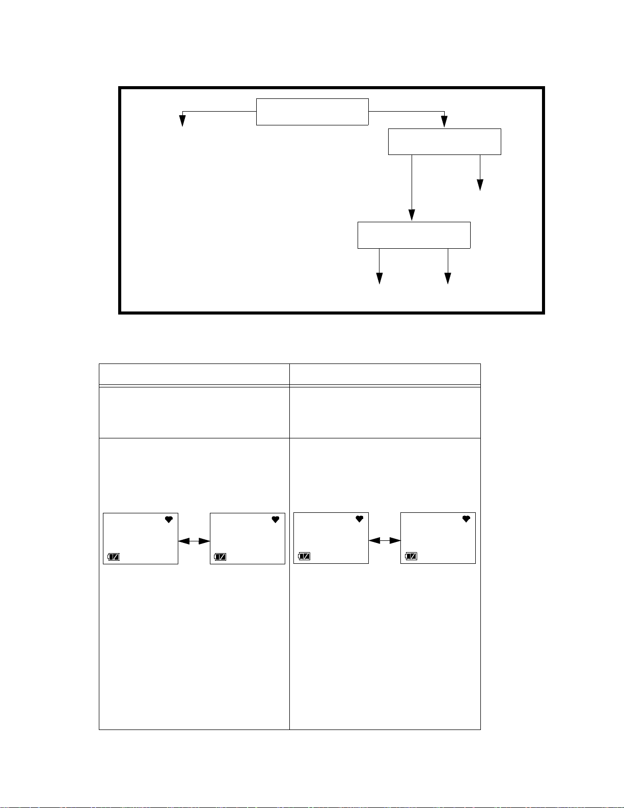
9. At the end of the countdown, the instrument analyzes the results. Follow the flow chart to
Figure 6: Bump Test Flow Chart
Bump test passed?
Y N
A-CAL On?
Calibration passed?
Y N
(default is on)
B
C D
Y N
A
SO2
P
BMP / CAL
ppm
SO2
4.70
BMP /
ppm
AIR
SO2
F
BMP / CAL
ppm
SO2
0.90
BMP /
ppm
AIR
determine the bump test outcome.
Option A from Flow Chart Option B from Flow Chart
• Bump test passed • Bump test failed
• A-CAL set to OFF (factory setting is
ON)
1. The instrument indicates that the
channel passed the bump test. Use
AIR to scroll between the bump test
result and the bump test gas
reading.
2. Close the regulator.
3. Unscrew the regulator.
4. Remove the calibration cup.
5. Press and release POWER MODE
to return to the BUMP screen in the
BUMP menu.
6. Use AIR to scroll to START and
press and release POWER MODE
to enter Measuring Mode.
1. The instrument shows which
channels passed or failed the bump
test. The LED flashes and the
buzzer sounds. Use AIR to scroll
between the result and the reading.
2. Close the regulator.
3. Unscrew the regulator.
4. Remove the calibration cup.
5. Press and release POWER MODE
to return to the BUMP screen in the
BUMP menu.
6. Use AIR to scroll to START and
press and release POWER MODE
to enter Measuring Mode.
7. Calibrate the SC-04 as soon as
possible.
Find Quality Products Online at: sales@GlobalTestSupply.com
44 • Chapter 5: User Mode and Calibration SC-04 Operator’s Manual
www.GlobalTestSupply.com
Page 45
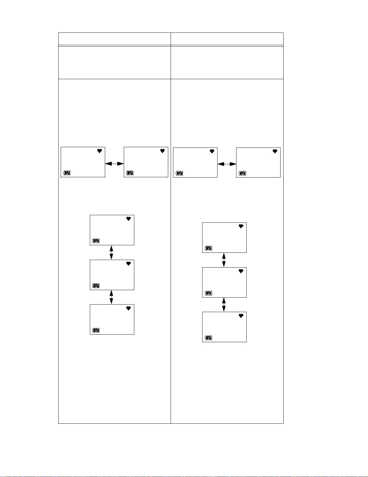
Option C from Flow Chart Option D from Flow Chart
SO2
0.00
CAL 60
ppm
SO2
0.00
APLY 60
ppm
SO2
F P
BMP / CAL
ppm
SO2
0.90
BMP /
ppm
SO2
4.70
/ CAL
ppm
AIR
AIR
SO2
0.00
CAL 60
ppm
SO2
0.00
APLY 60
ppm
SO2
F F
BMP / CAL
ppm
SO2
0.00
BMP /
ppm
SO2
0.90
/ CAL
ppm
AIR
AIR
• Bump test failed
• A-CAL set to ON (factory setting)
• Calibration passed
1. A calibration immediately and
automatically starts. Continue to
apply the calibration gas.
2. The calibration time is the
difference between the GAS.TIME
and the CAL.TIME values defined
in the BUMP.SET\SETTING item
in User Mode.
3. The instrument shows the pass/fail
results of the bump test/calibration.
Use AIR to scroll between the
results and the readings.
• Bump test failed
• A-CAL set to ON (factory setting)
• Calibration failed
1. A calibration immediately and
automatically starts. Continue to
apply the calibration gas.
2. The calibration time is the
difference between the GAS.TIME
and the CAL.TIME values defined
in the BUMP.SET\SETTING item
in User Mode.
3. The instrument shows the pass/fail
results of the bump test/calibration.
The LED flashes and the buzzer
sounds. Use AIR to scroll between
the results and the readings.
4. Close the regulator.
5. Unscrew the regulator.
Find Quality Products Online at: sales@GlobalTestSupply.com
SC-0 4 Operator’s Manual Chapter 5: User Mode and Calibration • 45
6. Remove the calibration cup.
7. Press and release POWER MODE
to return to the BUMP screen in the
BUMP menu.
8. Use AIR to scroll to START and
press and release POWER MODE
to enter Measuring Mode.
www.GlobalTestSupply.com
4. Close the regulator.
5. Unscrew the regulator.
6. Remove the calibration cup.
7. Press and release POWER MODE
to return to the BUMP screen in the
BUMP menu.
8. Use AIR to scroll to START and
press and release POWER MODE
to enter Measuring Mode.
Page 46

Performing a Calibration (GAS CAL)
GAS CAL
AIR
SO2
0.00
AIR
ppm
• Bump test the instrument before each day’s use with a known concentration of the target gas. A
bump test can be done in User Mode’s BUMP item or by applying gas in Measuring Mode.
The instrument does not need to be calibrated unless it does not pass the User Mode bump test
or does not respond appropriately, as defined by the user, in Measuring Mode.
• To fully calibrate the sensor, you must do a fresh air adjustment (AIR CAL) and a span
adjustment (A-CAL or E-CAL).
• The SC-04 can be calibrated using either A-CAL or E-CAL depending on the setting of the E-
CAL User Mode item.
• A-CAL (appears if E-CAL User Mode item is set to OFF): Apply gas for a period of
time, then press and release POWER MODE to perform the adjustment.
• E-CAL (appears if E-CAL User Mode item is set to something besides OFF): As soon as
gas is applied and the reading reaches 10% of the auto calibration value, the instrument
counts down from the number of seconds specified in the E-CAL User Mode item and
automatically performs the adjustment.
Performing a Fresh Air Adjustment (AIR)
1. Find a fresh air environment, an environment of normal oxygen content (20.9%) that is free of
toxic and combustible gases.
2. While in User Mode, press AIR to scroll to GAS CAL.
3. Press and release POWER MODE. The AIR item appears.
4. Press and release POWER MODE to enter the AIR menu.
5. To return to the AIR menu without performing a fresh air adjustment, press and release
POWER MODE.
46 • Chapter 5: User Mode and Calibration SC-04 Operator’s Manual
Find Quality Products Online at: sales@GlobalTestSupply.com
www.GlobalTestSupply.com
Page 47
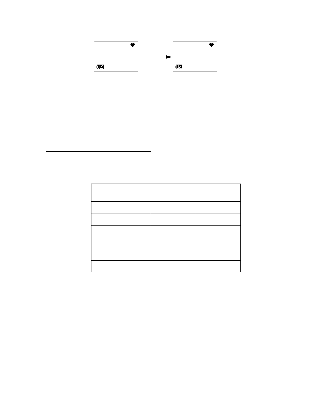
6. To perform a fresh air adjustment, press and hold AIR until the screen prompts you to release
AIR
HOLD
AIR
RELEASE
it.
7. If the fresh air adjustment passes, the instrument returns to the AIR item in the GAS CAL
menu.
8. If the fresh air adjustment fails, “FAIL AIR” displays. Press and release POWER MODE to
acknowledge the failure. See page 72.
Performing a Span Adjustment in A-CAL
The A-CAL item only appears if E-CAL in User Mode is set to OFF (factory setting). If E-CAL
is set to ON, see page 51 for calibration instructions.
Preparing for Span Adjustment
To adjust the span on the SC-04, you need:
• Calibration gas cylinder
Table 10: Calibration Concentration Limits
Channel
Ammonia 8 ppm 400 ppm
Chlorine 0.15 ppm 10.00 ppm
Hydrogen Cyanide 0.9 ppm 30.0 ppm
Nitrogen Dioxide 0.50 ppm 20.00 ppm
Phosphine 0.05 ppm 20.00 ppm
Sulfur Dioxide 0.50 ppm 100.00 ppm
• 0.25 LPM fixed flow regulator
• Non-absorbent tubing
• Calibration cup
1. Confirm that the SC-04’s calibration gas value matches the concentration listed on the
calibration gas cylinder as described on page 55.
Min. Cal.
Concentration
Max. Cal.
Concentration
SC-0 4 Operator’s Manual Chapter 5: User Mode and Calibration • 47
Find Quality Products Online at: sales@GlobalTestSupply.com
www.GlobalTestSupply.com
Page 48

2. Install the calibration cup onto the SC-04. Be sure the calibration cup is installed in the correct
POWER
MODE
AIR
Front ViewSide View
GAS CAL
A-CAL
SO2
5.00
A-CAL
ppm
direction and that it is pushed on all the way.
3. Use the tubing to connect the regulator to the inlet of the calibration cup (labeled “IN”).
Performing a Span Adjustment
1. While in User Mode, press AIR to scroll to GAS CAL.
2. Press and release POWER MODE. The AIR item appears.
3. Use AIR to scroll to the A-CAL item.
4. Press and release POWER MODE. The display shows the gas and its assigned calibration
value (see page 55 if the calibration value does not match the calibration gas cylinder’s
concentration).
5. For toxic gas cylinders, it is important to vent the regulator while installing it onto the
cylinder. Venting the regulator during installation helps prevent air from getting into the
cylinder and degrading the gas. Open the regulator by turning the knob counterclockwise and
install it onto the cylinder.
6. Press and release POWER MODE.
48 • Chapter 5: User Mode and Calibration SC-04 Operator’s Manual
Find Quality Products Online at: sales@GlobalTestSupply.com
www.GlobalTestSupply.com
Page 49

7. The gas reading flashes and the bottom of the screen alternates between “APPLY” and “A-
SO2
0.00
A-CAL
ppm
SO2
0.00
APPLY
ppm
CAL”.
NOTE: To back out of the gas application screen without performing the calibration,
press and release AIR and POWER MODE together.
8. Turn the regulator knob counterclockwise to open the regulator.
9. Allow the gas to flow for 1 minute for all gases except Cl2 and NH3. Allow Cl2 and NH3 gas
to flow for 2 minutes.
10. Press and release POWER MODE.
SC-0 4 Operator’s Manual Chapter 5: User Mode and Calibration • 49
Find Quality Products Online at: sales@GlobalTestSupply.com
www.GlobalTestSupply.com
Page 50

11. The table below describes the 2 calibration outcomes.
PASS
A-CAL
SO2
5.10
A-CAL
ppm
SO2
10.00
MAX .SPAN
ppm
SO2
FAIL
A-CAL
ppm
Calibration Passed Calibration Failed
1. The instrument indicates that the
calibration passed.
2. The instrument shows the current
gas reading.
3. If MAX.SPAN is set to ON
(default is OFF, see page 100), the
response reading’s maximum
adjustment is displayed. A
maximum span of 10.00 ppm
indicates that the reading could
have been adjusted up to 10.00
ppm. If the maximum span value is
close to the calibration gas value,
the sensor should be replaced soon.
1. The instrument indicates that the
calibration failed.
2. Close the regulator.
3. Unscrew the regulator.
4. Remove the calibration cup.
5. Press and release POWER MODE
to return to the A-CAL screen in
the A-CAL menu.
6. See “Troubleshooting” on page 72.
The maximum adjustment is either
twice the calibration value or full
scale, whichever is lower.
4. Close the regulator.
5. The instrument continues to the
START screen.
6. Remove the calibration cup.
7. Press and release POWER MODE
to enter Measuring Mode.
Find Quality Products Online at: sales@GlobalTestSupply.com
50 • Chapter 5: User Mode and Calibration SC-04 Operator’s Manual
www.GlobalTestSupply.com
Page 51
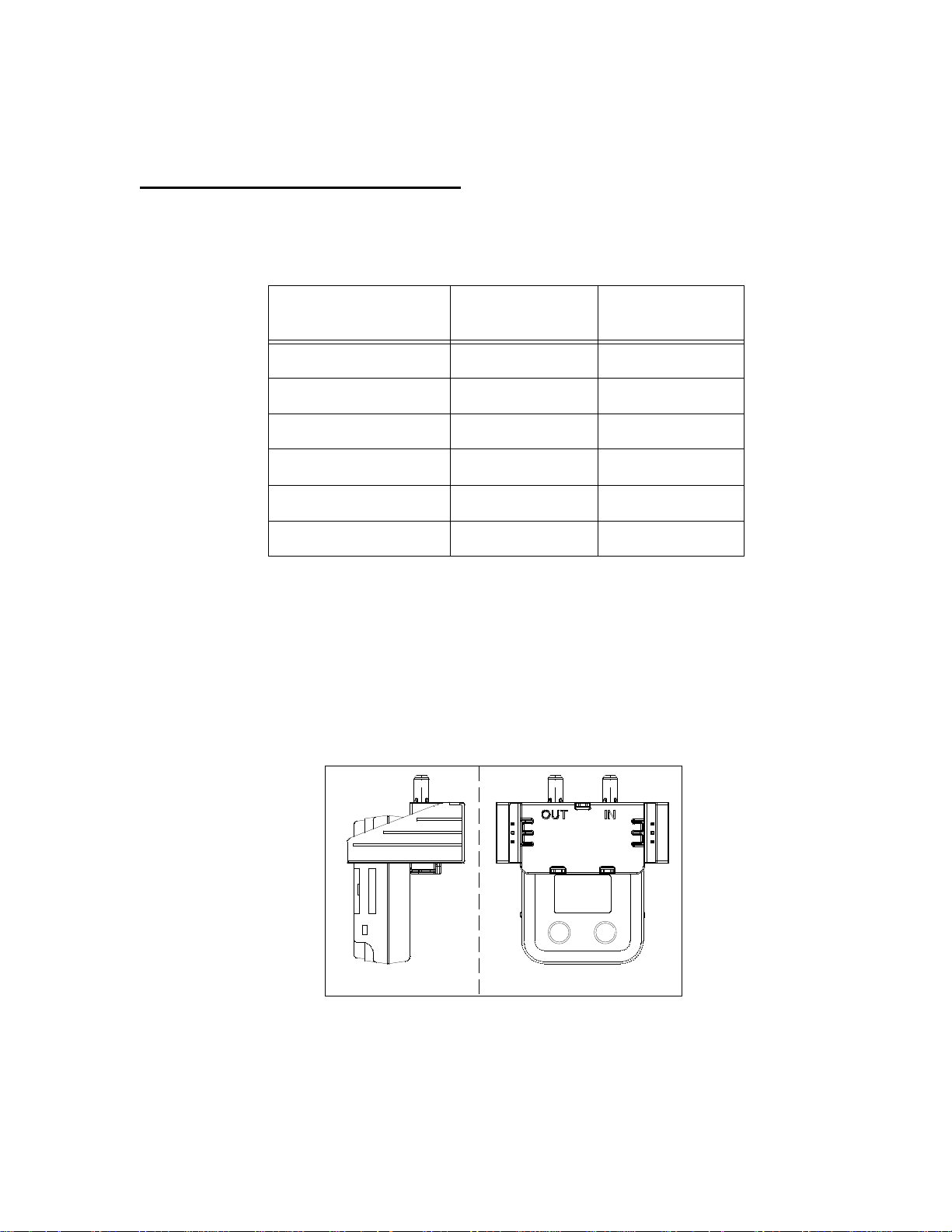
Performing a Span Adjustment in E-CAL
POWER
MODE
AIR
Front ViewSide View
The E-CAL item only appears if E-CAL in User Mode is set to ON (factory setting is OFF). If
E-CAL is set to OFF, see page 47 for calibration instructions.
Preparing for Span Adjustment
To adjust the span on the SC-04, you need:
• Calibration gas cylinder
Table 11: Calibration Concentration Limits
Channel
Ammonia 8 ppm 400 ppm
Chlorine 0.15 ppm 10.00 ppm
Hydrogen Cyanide 0.9 ppm 30.0 ppm
Nitrogen Dioxide 0.50 ppm 20.00 ppm
Phosphine 0.05 ppm 20.00 ppm
Sulfur Dioxide 0.50 ppm 100.00 ppm
Min. Cal.
Concentration
Max. Cal.
Concentration
• 0.25 LPM fixed flow regulator
• Non-absorbent tubing
• Calibration cup
1. Confirm that the SC-04’s calibration gas value matches the concentration listed on the
calibration gas cylinder as described on page 55.
2. Install the calibration cup onto the SC-04. Be sure the calibration cup is installed in the correct
direction and that it is pushed on all the way.
3. Use the tubing to connect the regulator to the inlet of the calibration cup (labeled “IN”).
SC-0 4 Operator’s Manual Chapter 5: User Mode and Calibration • 51
Find Quality Products Online at: sales@GlobalTestSupply.com
www.GlobalTestSupply.com
Page 52

Performing a Calibration
GAS CAL
E-CAL
SO2
5.00
E-CAL
ppm
SO2
0.00
GAS IN
ppm
1. While in User Mode, press AIR to scroll to GAS CAL.
2. Press and release POWER MODE. The AIR item appears.
3. Use AIR to scroll to the E-CAL item.
4. Press and release POWER MODE. The display shows the gas and its assigned calibration
value (see page 55 if the calibration value does not match the calibration gas cylinder’s
concentration).
5. Press and release POWER MODE.
6. The gas reading flashes and the bottom of the screen says “GAS IN”.
7. For toxic gas cylinders, it is important to vent the regulator while installing it onto the
cylinder. Venting the regulator during installation helps prevent air from getting into the
cylinder and degrading the gas. Open the regulator by turning the knob counterclockwise and
install it onto the cylinder.
52 • Chapter 5: User Mode and Calibration SC-04 Operator’s Manual
Find Quality Products Online at: sales@GlobalTestSupply.com
www.GlobalTestSupply.com
Page 53

8. Once the gas reading reaches 10% of the auto calibration value, the screen starts counting
SO2
0.50
CAL 60
ppm
SO2
0.50
APLY 60
ppm
down from the time specified in the E-CAL User Mode item. In the example below, E-CAL
is set to 60 seconds.
NOTE: RKI Instruments recommends an E-CAL setting of 120 seconds for Cl2 and
NH3 and 60 seconds for all other gases.
To back out of the gas application screen without performing the calibration, press and
release AIR and POWER MODE together.
If the reading never reaches 10% of the auto calibration value, press and release POWER
MODE to fail the calibration.
9. At the end of the countdown, the instrument makes the span adjustment.
SC-0 4 Operator’s Manual Chapter 5: User Mode and Calibration • 53
Find Quality Products Online at: sales@GlobalTestSupply.com
www.GlobalTestSupply.com
Page 54

10. The table below describes the 2 calibration outcomes.
PASS
E-CAL
SO2
5.10
E-CAL
ppm
SO2
10.00
MAX .SPAN
ppm
SO2
FAIL
E-CAL
ppm
Calibration Passed Calibration Failed
1. The instrument indicates that the
calibration passed.
2. The instrument shows the current
gas reading.
3. If MAX.SPAN is set to ON
(default is OFF, see page 100), the
response reading’s maximum
adjustment is displayed. A
maximum span of 10.00 ppm
indicates that the reading could
have been adjusted up to 10.00
ppm. If the maximum span value is
close to the calibration gas value,
the sensor should be replaced soon.
1. The instrument indicates that the
calibration failed.
2. Close the regulator.
3. Unscrew the regulator.
4. Remove the calibration cup.
5. Press and release POWER MODE
to return to the E-CAL screen in
the E-CAL menu.
6. See “Troubleshooting” on page 72.
The maximum adjustment is either
twice the calibration value or full
scale, whichever is lower.
4. Close the regulator.
5. The instrument continues to the
START screen.
6. Remove the calibration cup.
7. Press and release POWER MODE
to enter Measuring Mode.
Find Quality Products Online at: sales@GlobalTestSupply.com
54 • Chapter 5: User Mode and Calibration SC-04 Operator’s Manual
www.GlobalTestSupply.com
Page 55

Setting the Calibration Values in CAL--P
GAS CAL
A-CAL
SO2
5.00
A-CAL
ppm
CAL-P
SO2
CAL-P
ppm
SO2
5.00
CAL-P
ppm
1. While in User Mode, press AIR to scroll to GAS CAL.
2. Press and release POWER MODE. The AIR item appears.
3. Use AIR to scroll to the A-CAL item (E-CAL if E-CAL in User Mode is set to ON).
4. Press and release POWER MODE. The Auto Cal screen displays.
5. Use AIR to scroll to CAL--P.
6. Press and release POWER MODE. The gas name displays.
7. Press and release POWER MODE. The calibration value begins to flash.
SC-0 4 Operator’s Manual Chapter 5: User Mode and Calibration • 55
Find Quality Products Online at: sales@GlobalTestSupply.com
www.GlobalTestSupply.com
Page 56

8. Use AIR to adjust the calibration gas value. The calibration gas value in the instrument must
match the value listed on the calibration gas cylinder you are using. Limits on the calibration
gas value are shown in the table below.
Table 12: Calibration Concentration Limits
Channel
Ammonia 8 ppm 400 ppm
Chlorine 0.15 ppm 10.00 ppm
Hydrogen Cyanide 0.9 ppm 30.0 ppm
Nitrogen Dioxide 0.50 ppm 20.00 ppm
Phosphine 0.05 ppm 20.00 ppm
Sulfur Dioxide 0.50 ppm 100.00 ppm
Min. Cal.
Concentration
Max. Cal
Concentration
9. Press and release POWER MODE to save the change. The calibration gas value stops flashing
and the unit returns to the gas name screen.
10. Use AIR to scroll to ESCAPE.
11. Press and release POWER MODE to return to the CAL--P item in the A-CAL menu.
12. Press AIR to scroll to ESCAPE.
13. Press and release POWER MODE to return to the A-CAL item in the GAS CAL menu.
14. See “Exiting the GAS CAL Menu” on page 56 to return to User Mode.
Exiting the GAS CAL Menu
1. While in the GAS CAL menu, press AIR to scroll to ESCAPE.
2. Press and release POWER MODE to return to the GAS CAL item in User Mode.
3. See “Entering Measuring Mode (START)” on page 71 to enter Measuring Mode.
56 • Chapter 5: User Mode and Calibration SC-04 Operator’s Manual
Find Quality Products Online at: sales@GlobalTestSupply.com
www.GlobalTestSupply.com
Page 57
Setting Calibration Parameters (CAL SET)
CAL SET
CAL .RMDR
CAL .RMDR
CAL .INT
The CAL SET menu has 4 items: CAL.RMDR, CAL.INT, CAL.EXPD, and ESCAPE.
1. While in User Mode, press AIR to scroll to CAL SET.
2. Press and release POWER MODE. The CAL.RMDR item appears.
CAL.RMDR
ON (factory setting): The SC-04 gives an indication at start up if it is due for calibration. The type
of indication depends on the CAL.EXPD setting (see page 58).
OFF: The SC-04 does not give an indication at start up if it is due for calibration.
1. After entering the CAL SET menu, press AIR to scroll to CAL.RMDR.
2. Press and release POWER MODE. The current setting flashes.
3. Use AIR to display the desired setting.
4. Press and release POWER MODE to save the setting and return to the CAL.RMDR item in
the CAL SET menu.
5. See “Exiting the CAL SET Menu” on page 58 to return to User Mode.
CAL.INT
This setting defines the amount of time between calibrations and can be set in 1 day increments.
The minimum setting is 1 day and the maximum setting is 1000 days. The factory setting is 90
days.
1. After entering the CAL SET menu, press AIR to scroll to CAL.INT.
SC-0 4 Operator’s Manual Chapter 5: User Mode and Calibration • 57
Find Quality Products Online at: sales@GlobalTestSupply.com
www.GlobalTestSupply.com
Page 58

2. Press and release POWER MODE. The current setting flashes.
CAL .EXPD
3. Use AIR to display the desired setting.
4. Press and release POWER MODE to save the setting and return to the CAL.INT item in the
CAL SET menu.
5. See “Exiting the CAL SET Menu” on page 58 to return to User Mode.
CAL.EXPD
This item defines what indication is given during start up when calibration is due and
CAL.RMDR is set to ON (factory setting).
CONFIRM (factory setting): The SC-04 gives an indication at start up if calibration is past due.
Press and release AIR to continue without calibrating or press and release POWER MODE to
enter User Mode and perform a calibration.
CANT.USE
release POWER MODE to enter User Mode and perform a calibration. Pressing AIR has no
effect. A successful calibration must be performed in order to use the instrument.
NONE
acknowledge the indication. If desired, press POWER MODE to enter User Mode and perform a
calibration. The warm-up sequence continues on its own.
1. After entering the CAL SET menu, press AIR to scroll to CAL.EXPD.
2. Press and release POWER MODE. The current setting flashes.
3. Use AIR to display the desired setting.
4. Press and release POWER MODE to save the setting and return to the CAL.EXPD item in the
CAL SET menu.
5. See “Exiting the CAL SET Menu” on page 58 to return to User Mode.
: The SC-04 gives an indication at start up that calibration is past due. Press and
: The SC-04 gives an indication at startup that calibration is past due. It is not necessary to
Exiting the CAL SET Menu
1. While in the CAL SET menu, press AIR to scroll to ESCAPE.
2. Press and release POWER MODE to return to the CAL SET item in User Mode.
3. See “Entering Measuring Mode (START)” on page 71 to enter Measuring Mode.
58 • Chapter 5: User Mode and Calibration SC-04 Operator’s Manual
Find Quality Products Online at: sales@GlobalTestSupply.com
www.GlobalTestSupply.com
Page 59

Setting Bump Test Parameters (BUMP.SET)
BUMP .SET
SETTING
SETTING
GAS .TIME
The BUMP.SET menu has 5 items: SETTING, BP.RMDR, BP.INT, BP.EXPD, and ESCAPE.
1. While in User Mode, press AIR to scroll to BUMP.SET.
2. Press and release POWER MODE. The SETTING item appears.
SETTING
The SETTING menu has 5 items: GAS.TIME, CHECK, CAL.TIME, A-CAL, and ESCAPE.
1. After entering the BUMP.SET menu, press AIR to scroll to SETTING.
2. Press and release POWER MODE. The GAS.TIME item appears.
GAS.TIME
The GAS.TIME is the amount of time that the instrument is exposed to gas during a bump test.
The available choices are 30 seconds (factory setting), 45 seconds, 60 seconds, and 90 seconds.
1. After entering the SETTING menu, press AIR to scroll to GAS.TIME.
2. Press and release POWER MODE. The current setting flashes.
3. Use AIR to display the desired setting.
4. Press and release POWER MODE to save the setting and return to the GAS TIME item in the
SETTING menu.
5. See “Exiting the SETTING Menu” on page 61 to return to BUMP.SET menu.
SC-0 4 Operator’s Manual Chapter 5: User Mode and Calibration • 59
Find Quality Products Online at: sales@GlobalTestSupply.com
www.GlobalTestSupply.com
Page 60
CHECK
CHECK
CAL .TIME
CHECK is the bump test tolerance value and is represented as a percentage of the calibration gas
concentration. It is the percentage that the bump test reading can differ from the auto calibration
value and still be considered a passed bump test. If the bump test reading differs more, the bump
test fails. The available values are 10%, 20%, 30%, 40%, and 50% (factory setting).
1. After entering the SETTING menu, press AIR to scroll to CHECK.
2. Press and release POWER MODE. The current setting flashes.
3. Use AIR to display the desired setting.
4. Press and release POWER MODE to save the setting and return to the CHECK item in the
SETTING menu.
5. See “Exiting the SETTING Menu” on page 61 to return to BUMP.SET menu.
CAL.TIME
The CAL.TIME is the total time the instrument is exposed to calibration gas if A-CAL is set to
ON and a bump test fails. The bump test time is deducted from the calibration time. For example,
if the CAL.TIME is set to 90 seconds and the GAS.TIME is set to 30 seconds, if the bump test
fails, the SC-04 is only exposed to gas for an additional 60 seconds. The available values are 90
seconds (factory setting), and 120 seconds.
1. After entering the SETTING menu, press AIR to scroll to CAL.TIME.
2. Press and release POWER MODE. The current setting flashes.
3. Use AIR to display the desired setting.
4. Press and release POWER MODE to save the setting and return to the CAL.TIME item in the
SETTING menu.
5. See “Exiting the SETTING Menu” on page 61 to return to BUMP.SET menu.
60 • Chapter 5: User Mode and Calibration SC-04 Operator’s Manual
Find Quality Products Online at: sales@GlobalTestSupply.com
www.GlobalTestSupply.com
Page 61
A-CAL
A-CAL
BP .RMDR
ON (factory setting): If a bump test fails, the unit automatically begins a calibration.
OFF: If a bump test fails, the unit does not automatically begin a calibration.
1. After entering the SETTING menu, press AIR to scroll to A-CAL.
2. Press and release POWER MODE. The current setting flashes.
3. Use AIR to display the desired setting.
4. Press and release POWER MODE to save the setting and return to the A-CAL item in the
SETTING menu.
5. See “Exiting the SETTING Menu” on page 61 to return to BUMP.SET menu.
Exiting the SETTING Menu
1. While in the SETTING menu, press AIR to scroll to ESCAPE.
2. Press and release POWER MODE to return to the SETTING item in the BUMP.SET menu.
3. See “Exiting the BUMP.SET Menu” on page 63 to return to User Mode.
BP.RMDR
ON: The SC-04 gives an indication at start up if it is due for bump testing. The type of indication
depends on the BP.EXPD setting (see page 62). If the instrument is not due for bump testing, a
check mark appears in the lower left corner of the LCD.
OFF (factory setting): The SC-04 does not give an indication at start up if it is due for bump
testing.
1. After entering the BUMP.SET menu, press AIR to scroll to BP.RMDR.
2. Press and release POWER MODE. The current setting flashes.
3. Use AIR to display the desired setting.
4. Press and release POWER MODE to save the setting and return to the BP.RMDR item in the
BUMP.SET menu.
5. See “Exiting the BUMP.SET Menu” on page 63 to return to User Mode.
SC-0 4 Operator’s Manual Chapter 5: User Mode and Calibration • 61
Find Quality Products Online at: sales@GlobalTestSupply.com
www.GlobalTestSupply.com
Page 62

BP.INT
BP .INT
BP .EXPD
This setting defines the amount of time between bump tests and can be set in 1 day increments.
The minimum setting is 0 days and the maximum setting is 30 days (factory setting).
1. After entering the BUMP.SET menu, press AIR to scroll to BP.INT.
2. Press and release POWER MODE. The current setting flashes.
3. Use AIR to display the desired setting.
4. Press and release POWER MODE to save the setting and return to the BP.INT item in the
BUMP.SET menu.
5. See “Exiting the BUMP.SET Menu” on page 63 to return to User Mode.
BP.EXPD
This item defines what indication is given during start up when a bump test is due and BP.RMDR
is set to ON (factory setting is OFF).
CONFIRM (factory setting): The SC-04 gives an indication at start up if a bump test is past due.
Press and release AIR to continue without bump testing or press and release POWER MODE to
enter User Mode and perform a bump test.
CANT.USE: The SC-04 gives an indication at start up that a bump test is past due. Press and
release POWER MODE to enter User Mode and perform a bump test. Pressing AIR has no effect.
A successful bump test must be performed in order to use the instrument.
NONE: The SC-04 gives an indication at startup that a bump test is past due. It is not necessary to
acknowledge the indication. If desired, press POWER MODE to enter User Mode and perform a
bump test. The warm-up sequence continues on its own.
1. After entering the BUMP.SET menu, press AIR to scroll to BP.EXPD.
2. Press and release POWER MODE. The current setting flashes.
3. Use AIR to display the desired setting.
4. Press and release POWER MODE to save the setting and return to the BP.EXPD item in the
BUMP.SET menu.
5. See “Exiting the BUMP.SET Menu” on page 63 to return to User Mode.
62 • Chapter 5: User Mode and Calibration SC-04 Operator’s Manual
Find Quality Products Online at: sales@GlobalTestSupply.com
www.GlobalTestSupply.com
Page 63

Exiting the BUMP.SET Menu
ALARM-P
SO2
ALARM-P
ppm
AIR
AIR
AIR
SO2
ALARM-P
ppm
DEF .ALMP
ESCAPE
1. While in the BUMP.SET menu, press AIR to scroll to ESCAPE.
2. Press and release POWER MODE to return to the BUMP.SET item in User Mode.
3. See “Entering Measuring Mode (START)” on page 71 to enter Measuring Mode.
Alarm Settings (ALARM--P)
The ALARM--P menu has 3 items: ALARM--P, DEF.ALMP, and ESCAPE.
1. While in User Mode, press AIR to scroll to ALARM--P.
2. Press and release POWER MODE. The first screen displays.
Setting the Alarm Points
1. After entering the ALARM-P menu, press AIR to scroll to the gas name.
2. Press and release POWER MODE.
SC-0 4 Operator’s Manual Chapter 5: User Mode and Calibration • 63
Find Quality Products Online at: sales@GlobalTestSupply.com
www.GlobalTestSupply.com
Page 64

3. The Warning setpoint flashes.
SO2
2.00
WARNING
ppm
SO2
5.00
ALARM
ppm
SO2
100.00
ALARM H
ppm
SO2
5.00
STEL
ppm
SO2
2.00
STEL
ppm
SO2
ALARM-P
ppm
For all settings:
1) AIR to adjust
2) POWER MODE
to save and
continue
DEF .ALMP
4. Use AIR to adjust the Warning setpoint. The alarm setpoint limitations are shown in the table
below.
Channel Alarm Point Limitations
Cl
0.15 ppm WARNING ALARM ALARM H 20.00 ppm
2
HCN 0.9 ppm WARNING ALARM ALARM H 30.0 ppm
NH
3
NO
2
PH
3
SO
2
5. Press and release POWER MODE to save the setting.
6. Repeat Step 4 and Step 5 for the Alarm, Alarm H, STEL and TWA settings.
7. The instrument returns to the channel selection screen.
8. See “ESCAPE” on page 65 to return to User Mode.
8.0 ppm WARNING ALARM ALARM H 400.0 ppm
0.50 ppm WARNING ALARM ALARM H 20.00 ppm
0.05 ppm WARNING ALARM ALARM H 20.00 ppm
0.50 ppm WARNING ALARM ALARM H 100.00 ppm
Defaulting the Alarm Points
Defaulting the alarm points defaults them back to factory settings as outlined in Table 2 on page 8
or to the settings saved in the SAVE-AP item in Gas Select Mode if you performed a SAVE-AP
operation.
1. After entering the ALARM-P menu, press AIR to scroll to DEF.ALMP.
64 • Chapter 5: User Mode and Calibration SC-04 Operator’s Manual
Find Quality Products Online at: sales@GlobalTestSupply.com
www.GlobalTestSupply.com
Page 65

2. Press POWER MODE to enter the DEF.ALMP item.
LUNCH
3. Press POWER MODE to perform an alarm default. Press AIR to return to the DEF.ALMP
item in the ALARM-P menu.
4. The instrument asks if you’re sure you want to default the alarm points.
5. Press POWER MODE to default the alarm points. Press AIR to return to the DEF.ALMP
item in the ALARM-P menu.
6. See “ESCAPE” on page 65 to return to User Mode.
ESCAPE
1. While in the ALARM-P menu, press AIR to scroll to ESCAPE.
2. Press and release POWER MODE to return to the ALARM--P item in User Mode.
3. See “Entering Measuring Mode (START)” on page 71 to enter Measuring Mode.
Updating the Lunch Break Setting (LUNCH)
OFF (factory setting): The SC-04 automatically starts new TWA and PEAK reading collection
and resets the time in operation at startup.
ON: The Lunch Break Screen displays during startup. From this screen, you can choose to
continue accumulating TWA and PEAK readings and the time in operation from the last time the
SC-04 was used or start collecting new readings and reset the time in operation.
1. While in User Mode, press AIR to scroll to LUNCH.
2. Press and release POWER MODE. The current setting flashes.
3. Use AIR to display the desired setting.
4. Press and release POWER MODE to save the setting and return to the LUNCH item in User
Mode.
5. See “Entering Measuring Mode (START)” on page 71 to enter Measuring Mode.
SC-0 4 Operator’s Manual Chapter 5: User Mode and Calibration • 65
Find Quality Products Online at: sales@GlobalTestSupply.com
www.GlobalTestSupply.com
Page 66

Setting the Confirmation Beep and
BEEP
BEEP .SEL
BEEP .SEL
Non-Compliance Indicator (BEEP)
The BEEP menu has 3 items: BEEP.SEL, BEEP.INT, and ESCAPE.
1. While in User Mode, press AIR to scroll to BEEP.
2. Press and release POWER MODE. The BEEP.SEL item appears.
BEEP.SEL
BEEP.SEL defines what kind of confirmation or non-compliance indication you want to occur in
Measuring Mode. The available choices are:
OFF (factory setting): The SC-04 does not provide a confirmation alert or non-compliance
indicator.
LED: The SC-04’s LED double flashes as often as defined by the BEEP.INT parameter to verify
that the instrument is operating.
BUZZER: The SC-04’s buzzer double beeps as often as defined by the BEEP.INT parameter to
verify that the instrument is operating.
LED+BUZ: The SC-04’s LED double flashes and the buzzer double beeps as often as defined by
the BEEP.INT parameter to verify that the instrument is operating.
BMP/CAL
CONFIRM (factory setting) or NONE, the SC-04’s LED double flashes as often as defined by
the BEEP.INT parameter to indicate a non-compliance. Once a bump test or calibration
(depending on which is due) is done, the LED stop flashing.
1. While in the BEEP menu, press AIR to scroll to BEEP.SEL.
2. Press and release POWER MODE. The current setting flashes.
: If a bump test or a calibration is due and if BP.EXPD or CAL.EXPD is set to
3. Use AIR to display the desired setting.
66 • Chapter 5: User Mode and Calibration SC-04 Operator’s Manual
Find Quality Products Online at: sales@GlobalTestSupply.com
www.GlobalTestSupply.com
Page 67

4. Press and release POWER MODE to save the setting and return to the BEEP.SEL item in the
BEEP .INT
BL TIME
BEEP menu.
5. See “ESCAPE” on page 67 to return to User Mode.
BEEP.INT
The BEEP.INT parameter defines how often the confirmation alert or non-compliance indicator
selected in BEEP.SEL occurs. This setting only applies if the BEEP.SEL parameter is set to
something other than OFF (factory setting). The available choices are 0.5 minutes and 1-99
minutes in 1 minute increments. The factory setting is 5 minutes.
1. While in the BEEP menu, press AIR to scroll to BEEP.INT.
2. Press and release POWER MODE. The current setting flashes.
3. Use AIR to display the desired setting.
4. Press and release POWER MODE to save the setting and return to the BEEP.INT item in the
BEEP menu.
5. See “ESCAPE” on page 67 to return to User Mode.
ESCAPE
1. While in the BEEP menu, press AIR to scroll to ESCAPE.
2. Press and release POWER MODE to return to the BEEP item in User Mode.
3. See “Entering Measuring Mode (START)” on page 71 to enter Measuring Mode.
Updating the Backlight Time (BL TIME)
This setting defines how long the LCD backlight stays on when you press any button. The
minimum setting is OFF; the maximum setting is 255 seconds. The factory setting is 30 seconds.
1. While in User Mode, press AIR to scroll to BL TIME.
2. Press and release POWER MODE. The current setting flashes.
3. Use AIR to display the desired setting.
SC-0 4 Operator’s Manual Chapter 5: User Mode and Calibration • 67
Find Quality Products Online at: sales@GlobalTestSupply.com
www.GlobalTestSupply.com
Page 68
4. Press and release POWER MODE to save the setting and return to the BL TIME item in User
KEY .TONE
DISP .SET
Mode.
5. See “Entering Measuring Mode (START)” on page 71 to enter Measuring Mode.
Turning the Key Tone On/Off (KEY.TONE)
ON (factory setting): The instrument beeps when a button is pressed.
OFF: The instrument does not beep when a button is pressed.
1. While in User Mode, press AIR to scroll to KEY.TONE.
2. Press and release POWER MODE. The current setting flashes.
3. Use AIR to display the desired setting.
4. Press and release POWER MODE to save the setting and return to the KEY.TONE item in
User Mode.
5. See “Entering Measuring Mode (START)” on page 71 to enter Measuring Mode.
Display Mode Items (DISP.SET)
OFF: USER ID, STN ID, and BUZZ.VOL screens do not appear in Display Mode.
ON (factory setting): BUZZ.VOL screen appears in Display Mode. USER ID and STN ID
screens appear in Display Mode if ID DISP in Maintenance Mode is also set to ON (factory
setting is OFF).
1. While in User Mode, press AIR to scroll to DISP.SET.
2. Press and release POWER MODE. The current setting flashes.
3. Use AIR to display the desired setting.
4. Press and release POWER MODE to save the setting and return to the DISP.SET item in User
Mode.
5. See “Entering Measuring Mode (START)” on page 71 to enter Measuring Mode.
68 • Chapter 5: User Mode and Calibration SC-04 Operator’s Manual
Find Quality Products Online at: sales@GlobalTestSupply.com
www.GlobalTestSupply.com
Page 69

Zero Suppression (ZERO.SUP)
E-CAL
This item only appears if ZSUP.DSP is set to ON in Maintenance Mode (factory setting is OFF).
The ZERO.SUP setting is not intended for field adjustment. The default setting is ON.
Zero
Sensor
Suppression
Val ue
Cl
2
HCN 0.5 ppm
NH
3
NO
2
PH
3
SO
2
0.10 ppm
4 ppm
0.30 ppm
0.02 ppm
0.20 ppm
Zero Follower (ZERO.FLW)
This item only appears if ZFLW.DSP is set to ON in Maintenance Mode (factory setting is OFF).
The ZERO.FLW setting is not intended for field adjustment. The default setting is ON.
Turning Easy Calibration On/Off (E-CAL)
OFF (factory setting): Auto Calibration (A-CAL) item appears in GAS CAL menu instead of
Easy Calibration (E-CAL).
XX seconds: Easy Calibration (E-CAL) item appears in GAS CAL menu instead of Auto
Calibration (A-CAL). During a calibration, the instrument counts down from the number of
seconds you select.
NOTE: RKI Instruments recommends an E-CAL setting of 120 seconds for Cl2 and NH3 and
60 seconds for all other gases.
1. While in User Mode, press AIR to scroll to E-CAL.
2. Press and release POWER MODE. The current setting flashes.
3. Use AIR to display the desired setting.
SC-0 4 Operator’s Manual Chapter 5: User Mode and Calibration • 69
Find Quality Products Online at: sales@GlobalTestSupply.com
www.GlobalTestSupply.com
Page 70

4. Press and release POWER MODE to save the setting and return to the E-CAL item in User
DATE
2020
4.21
10:40
PASS- W
Mode.
5. See “Entering Measuring Mode (START)” on page 71 to enter Measuring Mode.
Setting the Date/Time (DATE)
1. While in User Mode, place the cursor next to DATE.
2. Press and release POWER MODE. The date and time display with the year flashing.
3. Use AIR to display the desired year.
4. Press and release POWER MODE to save the setting. The month setting flashes.
5. Repeat Step 3 and Step 4 to enter the month, day, hours, and minutes settings. The date and
time are saved and the instrument returns to the DATE item in User Mode.
6. See “Entering Measuring Mode (START)” on page 71 to enter Measuring Mode.
Turning the Password On/Off (PASS-W)
ON: The SC-04 prompts you for a password when you enter User Mode. The factory-set
password is 0405 but it can be changed.
OFF (factory setting): No password is required to enter User Mode.
1. While in User Mode, press AIR to scroll to PASS-W.
2. Press and release POWER MODE. The current setting flashes.
3. Use AIR to display the desired setting.
4. If you selected OFF, press and release POWER MODE to save the setting and return to the
PASS- W item in User Mode.
If you selected ON, continue with Step 5.
70 • Chapter 5: User Mode and Calibration SC-04 Operator’s Manual
www.GlobalTestSupply.com
Find Quality Products Online at: sales@GlobalTestSupply.com
Page 71
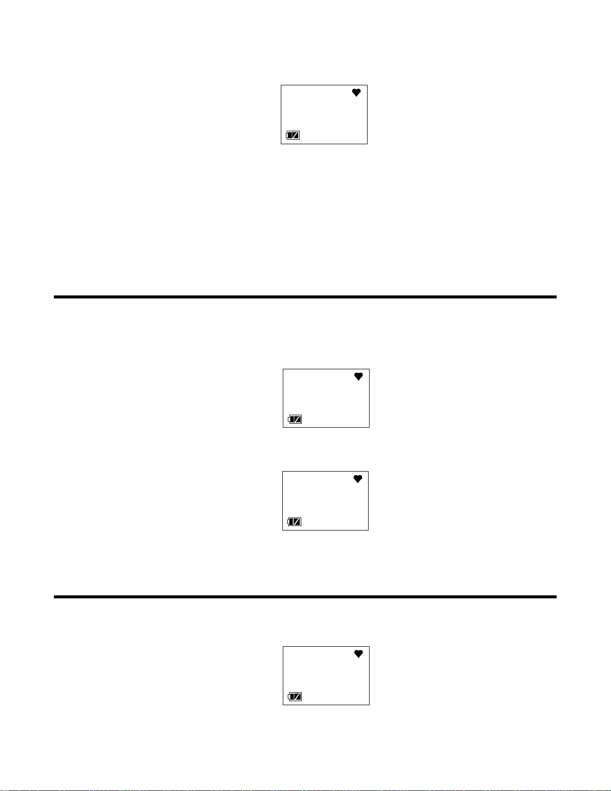
5. Press and release POWER MODE. The Set Password Screen appears. The current password
0000
PASS- W
ROM/SUM
6180
72F8
ROM/SUM
START
appears and the first digit flashes.
6. Use AIR to display a number from 0 to 9.
7. Press and release POWER MODE to enter the selection and advance to the next number. To
go back a number, press and hold AIR and POWER MODE for a few seconds.
8. Repeat Step 6 and Step 7 to select the remaining numbers. When you press and release
POWER MODE to enter the last number, the password is saved and the instrument returns to
the PASS-W item in User Mode.
9. See “Entering Measuring Mode (START)” on page 71 to enter Measuring Mode.
Viewing the ROM/SUM (ROM/SUM)
The ROM/SUM screen shows the instrument’s firmware version and firmware checksum.
1. While in User Mode, press AIR to scroll to ROM/SUM.
2. Press and release POWER MODE. The screen shows the ROM/SUM. The ROM is the top
value and the SUM is the bottom value.
3. Press and release POWER MODE to return to the ROM/SUM item in User Mode.
4. See “Entering Measuring Mode (START)” on page 71 to enter Measuring Mode.
Entering Measuring Mode (START)
1. While in User Mode, press AIR to scroll to START.
2. Press and release POWER MODE. The instrument begins its warmup sequence.
SC-0 4 Operator’s Manual Chapter 5: User Mode and Calibration • 71
www.GlobalTestSupply.com
Find Quality Products Online at: sales@GlobalTestSupply.com
Page 72

Chapter 6: Maintenance
Overview
This chapter describes troubleshooting procedures for the SC-04. It also includes procedures for
replacing the batteries and replacing various consumable parts.
WARNING: RKI Instruments recommends that service, calibration, and repair of RKI gas
detectors be performed by personnel properly trained for this work. Replacing the
sensor and other parts with original equipment does not affect the intrinsic safety
of the instrument.
AVERTISSEMENT: RKI Instruments recommande que le service, l'étalonnage et la
réparation des détecteurs de gaz RKI soient effectués par du personnel
dûment formé à ces travaux. Le remplacement du capteur et d'autres
pièces par l'équipement d'origine n'affecte pas la sécurité intrinsèque de
l'instrument.
Troubleshooting
The troubleshooting table describes error messages, symptoms, probable causes, and
recommended action for problems you may encounter with the SC-04.
Symptoms Probable Causes Recommended Action
• The LCD is blank. • The unit got turned off.
• The batteries needs to be
• The battery cover may not be
Table 13: Troubleshooting the SC-04
1. To turn on the unit, press and briefly
replaced.
completely closed.
2. Replace the batteries.
3. Be sure the battery cover is
4. If the difficulties continue, contact
hold POWER MODE.
completely closed and that the
screw is tight.
RKI Instruments, Inc. for further
instruction.
72 • Chapter 6: Maintenance SC-04 Operator’s Manual
Find Quality Products Online at: sales@GlobalTestSupply.com
www.GlobalTestSupply.com
Page 73

Table 13: Troubleshooting the SC-04
Symptoms Probable Causes Recommended Action
• The LCD shows an
abnormally high
reading but other gas
detection instruments
• Sensor filter needs to be
replaced.
• The SC-04 needs to be
recalibrated.
do not.
• The sensor needs
replacement.
• Calibration fails. • The calibration value does
not match the cylinder gas
concentration.
• The sample gas is not
reaching the sensor because
of a bad connection.
• The calibration cylinder is
out of gas or is outdated.
• The sensor needs
replacement.
1. Replace the sensor filter.
2. Recalibrate the unit.
3. If the difficulties continue, replace
the sensor and calibrate.
4. Allow instruments with NH
3
sensors 2 hours of sensor warmup
prior to operation if the sensor or
batteries are newly installed or if the
unit’s batteries have been
completely discharged.
5. If the difficulties continue, contact
RKI Instruments, Inc. for further
instruction.
1. Make sure the SC-04 has been
properly set up for calibration.
2. Check all calibration tubing for
leaks or for any bad connections.
3. Verify that the calibration cylinder
contains an adequate supply of fresh
test sample.
4. If the fail condition continues,
replace the sensor.
5. If the difficulties continue, contact
RKI Instruments, Inc. for further
instruction.
• Heart symbol at the
top of the screen
becomes steadily on
or disappears.
• A microprocessor error has
occurred.
• Contact RKI Instruments, Inc. for
further instruction.
SC-0 4 Operator’s Manual Chapter 6: Maintenance • 73
Find Quality Products Online at: sales@GlobalTestSupply.com
www.GlobalTestSupply.com
Page 74

Replacing the Batteries (Alkaline or Ni-MH)
Figure 7: Releasing the Alligator or Belt Clip
WARNING: To prevent ignition of a hazardous atmosphere, batteries must only be changed in
an area known to be nonhazardous.
AVERTISSEMENT: Pour éviter l'inflammation d'une atmosphère dangereuse, la batterie ne
doit être remplacée que dans une zone non dangereuse.
WARNING: Use only Duracell MN2400 or PC2400 or Eneloop BK-4MCC batteries to
maintain the QPS classification of the SC-04. Use of other batteries will void the
QPS classification and may void the warranty. Do not mix old/new or different
types of batteries.
AVERTISSEMENT: Utiliser uniquement des piles Duracell MN 2400 ou PC 2400 ou
Eneloop BK-4MCC de maintenir la classification QPS de la SC-04.
L’utilisation d’autres piles annule la classification QPS et peut annuler
la garantie. Ne mélangez pas les anciennes/nouvelles ou différents types
de piles.
NOTE: If old batteries are completely out of charge (the unit does not power on), instruments
with NH3 sensors require 2 hours for sensor warmup before turning the instrument on
for normal operation.
Replace the batteries when the last bar in the battery icon is flashing.
1. Make sure the SC-04 is off.
2. Release the side of the alligator or belt clip that is opposite the hinge. You may need to o a
screwdriver to pry it open.
74 • Chapter 6: Maintenance SC-04 Operator’s Manual
Find Quality Products Online at: sales@GlobalTestSupply.com
www.GlobalTestSupply.com
Page 75

3. Rotate the captive battery cover screw counterclockwise.
Battery
Cover
Screw
Figure 8: Unscrew Battery Cover Screw
Battery Cover
Figure 9: Battery Cover Removal
Figure 10: Installing New Batteries
4. Remove the battery cover.
5. Remove the old batteries.
NOTE: New batteries must be installed within 5 minutes to avoid having to reset the
date/time.
6. Install the new AAA batteries. Follow the diagram shown in the battery compartment.
SC-0 4 Operator’s Manual Chapter 6: Maintenance • 75
Find Quality Products Online at: sales@GlobalTestSupply.com
7. Reinstall the battery cover and tighten the battery cover screw.
www.GlobalTestSupply.com
Page 76

8. If the instrument has been without batteries for more than 5 minutes, the date and time are
reset and need to be set again. When the new batteries are installed, the instrument
automatically turns on and displays the Date/Time Screen. Set the date and time as described
on page 70. Once the date and time are set, the instrument begins its warmup sequence. If you
do not set the date and time within 30 seconds, the instrument automatically begins its
warmup sequence.
Recharging the Batteries (Ni-MH Batteries Only)
Any battery charger capable of charging AAA Ni-MH batteries can be used to recharge the SC04’s Ni-MH batteries. RKI Instruments, Inc. recommends using one of the chargers specified on
page 83.
WARNING: To prevent ignition of a hazardous atmosphere, batteries must only be charged in
an area known to be nonhazardous.
NOTE: If old batteries have been completely discharged (the unit does not power on),
instruments with NH3 sensors require 2 hours for sensor warmup before turning the
instrument on for normal operation.
1. Remove the batteries from the SC-04 as described in Step 1 - Step 5 on page 74.
2. Install the Ni-MH batteries in the charger. See the battery charger’s manual for charging
instructions.
3. Put the batteries back in the SC-04 and reinstall the battery cover.
Replacing the Sensor Filter
NO2 and SO2 Sensors’ Filter: The H2S filter disk is tan in color. The filter should be replaced
every 6 months.
HCN Sensor Filter: The H2S filter disk is dark gray in color. The filter should be replaced every 6
months.
Sensor Filter: The humidity filter disk is white in color. The filter should be replaced every 6
PH
3
months.
NH3 Sensor Filter: The humidity filter is white in color. The filter should be replaced every 6
months.
1. Verify that the SC-04 is off.
2. Remove the rubber boot, if installed.
76 • Chapter 6: Maintenance SC-04 Operator’s Manual
Find Quality Products Online at: sales@GlobalTestSupply.com
www.GlobalTestSupply.com
Page 77

3. Use a small Phillips screwdriver to unscrew the 4 screws that attached the front case to the
Figure 11: Unscrewing Case Screws
Screw, 4x
Front Case
Rear Case
Figure 12: Case Separation
rear case.
4. Turn the instrument right side up. The screws are not captive and may fall out. Be sure not to
lose them.
5. Remove the front case from the rear case.
6. Turn the front case upside down.
7. If the sensor stayed in the front case, remove the sensor.
SC-0 4 Operator’s Manual Chapter 6: Maintenance • 77
Find Quality Products Online at: sales@GlobalTestSupply.com
www.GlobalTestSupply.com
Page 78

8. The sensor filter sits in the middle of a black gasket. Pry the sensor filter out of the gasket.
Figure 13: Sensor Filter Location
Hydrophobic Filter
Sensor Gasket
Sensor Gasket
Sensor Filter
Sensor Filter
Front Case
FrontCase Inside ViewInstrument Side View
Rear Case
9. Install a new sensor filter. If the gasket got removed, install it with the flat side facing the
white hydrophobic filter.
10. If necessary, put the sensor in the socket on the rear case. The colored side faces away from
the rear case and the slots in the sensor line up with tabs in the socket.
CAUTION: Forcing a sensor into a socket without lining the sensor slots up with the
socket tabs may damage the sensor or socket.
11. Reinstall the front case to the rear case.
12. Reinstall the 4 screws that were removed in Step 3.
13. Reinstall the rubber boot, if being used.
78 • Chapter 6: Maintenance SC-04 Operator’s Manual
Find Quality Products Online at: sales@GlobalTestSupply.com
www.GlobalTestSupply.com
Page 79

Replacing the Hydrophobic Filter
Figure 14: Unscrewing Case Screws
Screw, 4x
Front Case
Rear Case
Figure 15: Case Separation
1. Verify that the SC-04 is off.
2. Remove the rubber boot, if installed.
3. Use a small Phillips screwdriver to unscrew the 4 screws that attached the front case to the
rear case.
4. Turn the instrument right side up. The screws are not captive and may fall out. Be sure not to
lose them.
5. Remove the front case from the rear case.
6. Turn the front case upside down.
7. If the sensor stayed in the front case, remove the sensor.
8. Carefully remove the sensor gasket and the sensor filter that sits in the middle of the sensor
gasket.
SC-0 4 Operator’s Manual Chapter 6: Maintenance • 79
Find Quality Products Online at: sales@GlobalTestSupply.com
www.GlobalTestSupply.com
Page 80
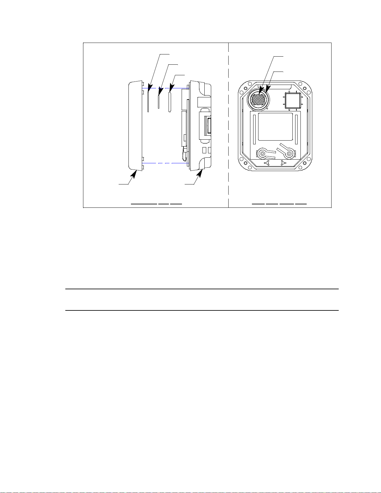
9. Remove the white hydrophobic filter.
Figure 16: Hydrophobic Filter Location
Hydrophobic Filter
Sensor Gasket
Sensor Gasket
Sensor Filter
Sensor Filter
Front Case
FrontCase Inside ViewInstrument Side View
Rear Case
10. Install a new hydrophobic filter.
11. Reinstall the sensor gasket with the flat side facing the white hydrophobic filter.
12. If the sensor filter came loose, reinstall it in the middle of the sensor gasket.
13. If necessary, put the sensor in the socket on the rear case. The colored side faces away from
the rear case and the slots in the sensor line up with tabs in the socket.
CAUTION: Forcing a sensor into a socket without lining the sensor slots up with the
socket tabs may damage the sensor or socket.
14. Reinstall the front case to the rear case.
15. Reinstall the 4 screws that were removed in Step 3.
16. Reinstall the rubber boot, if being used.
80 • Chapter 6: Maintenance SC-04 Operator’s Manual
Find Quality Products Online at: sales@GlobalTestSupply.com
www.GlobalTestSupply.com
Page 81

Replacing the Sensor
Figure 17: Unscrewing Case
Screw, 4x
Front Case
Rear Case
Figure 18: Case Separation
1. Verify that the SC-04 is off.
2. Remove the rubber boot, if installed.
3. Use a small Phillips screwdriver to unscrew the 4 screws that attached the front case to the
rear case.
4. Turn the instrument right side up. The screws are not captive and may fall out. Be sure not to
lose them.
5. Remove the front case from the rear case.
6. Turn the front case upside down.
7. Remove the old sensor. It will either be in its rear case socket or it will be stuck to the sensor
gasket in the front case.
SC-0 4 Operator’s Manual Chapter 6: Maintenance • 81
Find Quality Products Online at: sales@GlobalTestSupply.com
www.GlobalTestSupply.com
Page 82
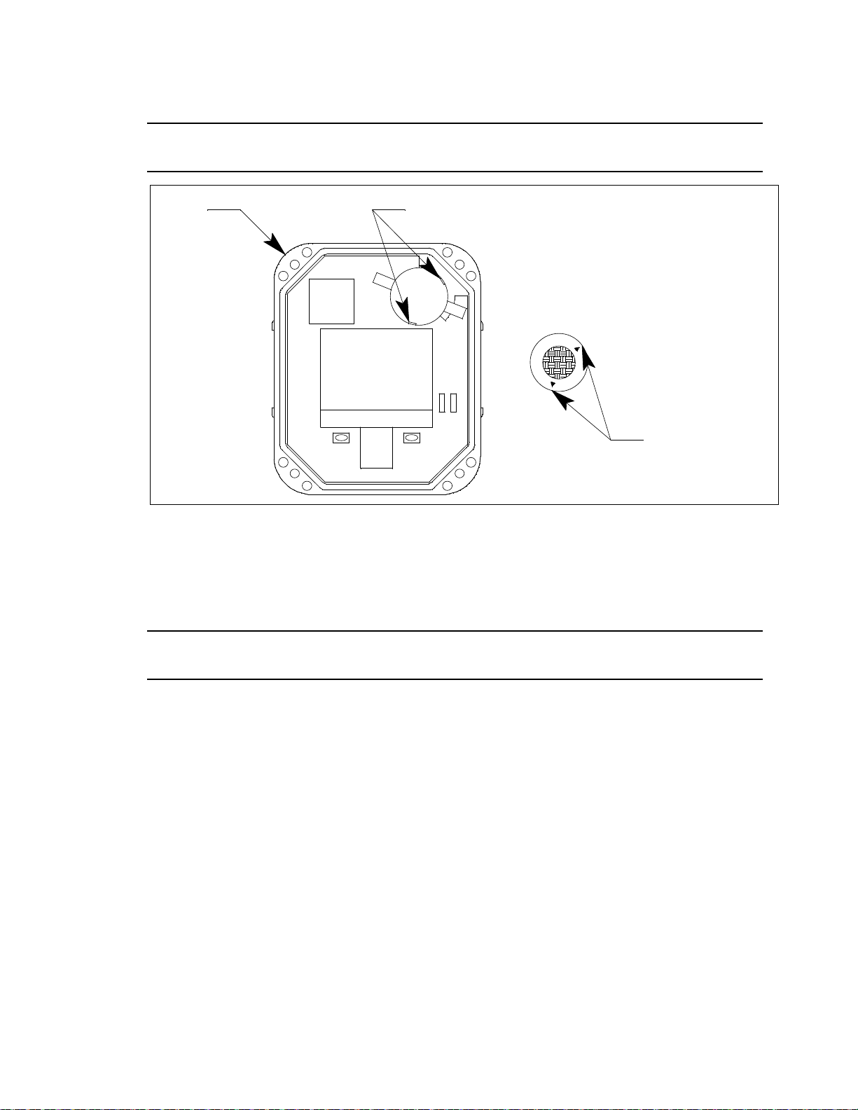
8. Install the new sensor in the socket on the rear case. The colored side faces away from the rear
Figure 19: Sensor Location
Tabs
Align Sensor Slots
with Tabs in Case
Rear
Case
case and the slots in the sensor line up with tabs in the socket.
CAUTION: Forcing a sensor into a socket without lining the sensor slots up with the
socket tabs may damage the sensor or socket.
9. Reinstall the front case to the rear case.
10. Reinstall the 4 screws that were removed in Step 3.
11. Reinstall the rubber boot, if being used.
NOTE: Instruments with newly installed NH3 sensors require 2 hours for sensor
warmup before initial calibration.
12. Calibrate the sensor as described on page 46.
82 • Chapter 6: Maintenance SC-04 Operator’s Manual
Find Quality Products Online at: sales@GlobalTestSupply.com
www.GlobalTestSupply.com
Page 83

Chapter 7: General Parts List
Table 14 lists part numbers for the SC-04’s replacement parts and accessories.
Table 14: General Parts List
Part Number Description
06-1248RK-03 Calibration kit tubing, 3 foot length
07-6033 Sensor gasket
10-1105-01 Screw, for securing front case to rear case
13-0112RK Wrist strap
13-0122 Belt clip
13-0128 Alligator clip
13-0204RK Pins for connecting alligator clip/belt clip
20-0325 Rubber boot
33-0175 Hydrophobic filter
33-7136 Humidity filter disk (white), for PH
33-7136-01 Humidity filter disk (white), for PH
33-7138 H
33-7138-01 H
33-7139 H
33-7139-01 H
S scrubber disk (dark gray), for HCN sensor, 5 pack
2
S scrubber disk (dark gray), for HCN sensor
2
S scrubber disk (tan), for NO2 and SO2 sensors, 5 pack
2
S scrubber disk (tan), for NO2 and SO2 sensors
2
33-7141 Humidity filter disk (white), for NH
33-7141-01 Humidity filter disk (white), for NH
sensor, 5 pack
3
sensor
3
sensor, 5 pack
3
sensor
3
47-5084RK USB/IrDA adapter module, Legasic, for use with all premier portables (without
USB cable)
47-5084RK-01 USB/IrDA adapter assembly, Legasic, for use with all premier portables (with mod-
ule and USB cable)
47-5085RK Cable, USB A to USB mini, 6 feet, for 47-5084RK USB/IrDA adapter module
49-1110RK AAA size alkaline battery
49-1312 AAA size Ni-MH battery
49-3105RK 4-battery AA/AAA charger with AC adapter and DC vehicle adapter
49-3106RK 12-battery AA/AAA charger with AC adapter
SC-0 4 Operator’s Manual Chapter 7: General Parts List • 83
Find Quality Products Online at: sales@GlobalTestSupply.com
www.GlobalTestSupply.com
Page 84

Table 14: General Parts List (Continued)
Part Number Description
71-0548 Operator’s Manual, SC-04 (this document)
71-0525 Operator’s Manual, 04 Series Datalogging Program
71-0526 Operator’s Manual, 04 Series Setup Program
81-0076RK-01 Calibration cylinder, zero air, 34 liter steel
81-0076RK-03 Calibration cylinder, zero air, 103 liter
81-0170RK-02 Calibration cylinder, 5 ppm SO
81-0170RK-04 Calibration cylinder, 5 ppm SO
81-0176RK-02 Calibration cylinder, 25 ppm NH
81-0176RK-04 Calibration cylinder, 25 ppm NH
81-0180RK-02 Calibration cylinder, 10 ppm NO
81-0180RK-04 Calibration cylinder, 10 ppm NO
81-0186RK-02 Calibration cylinder, 5 ppm PH
81-0190RK-02 Calibration cylinder, 5 ppm Cl
81-0190RK-04 Calibration cylinder, 5 ppm Cl
in nitrogen, 58 liter
2
in nitrogen, 34 liter aluminum
2
in nitrogen, 58 liter
3
in nitrogen, 34 liter aluminum
3
in nitrogen, 58 liter
2
in nitrogen, 34 liter aluminum
2
in nitrogen, 58 liter
3
in nitrogen, 58 liter
2
in nitrogen, 34 liter aluminum
2
81-0196RK-02 Calibration cylinder, 10 ppm HCN in nitrogen, 58 liter
81-0196RK-04 Calibration cylinder, 10 ppm HCN in nitrogen, 34 liter aluminum
81-1050RK-25 Regulator, fixed flow, 0.25 LPM, with gauge and knob, for 17 liter and 34 liter steel
cylinders (cylinders with external threads)
81-1051RK-25 Regulator, fixed flow, 0.25 LPM, with gauge and knob, for 34 liter aluminum, 58
liter, and 103 liter cylinders (cylinders with internal threads)
81-1146 Calibration cup
81-SC04CL2-LV Calibration kit for Cl
SC-04: 34 liter aluminum cylinder of 5 ppm Cl2 in N2,
2
regulator, tubing, calibration cup, case
81-SC04HCN-LV Calibration kit for HCN SC-04: 34 liter aluminum cylinder of 10 ppm HCN in N
,
2
regulator, tubing, calibration cup, case
81-SC04NO2-LV Calibration kit for NO
SC-04: 34 liter aluminum cylinder of 10 ppm NO2 in N2,
2
regulator, tubing, calibration cup, case
81-SC04PH3-LV Calibration kit for PH
SC-04: 34 liter aluminum cylinder of 0.5 ppm PH3 in N2,
3
regulator, tubing, calibration cup, case
84 • Chapter 7: General Parts List SC-04 Operator’s Manual
Find Quality Products Online at: sales@GlobalTestSupply.com
www.GlobalTestSupply.com
Page 85

Table 14: General Parts List (Continued)
Part Number Description
81-SC04SO2-LV Calibration kit for SO2 SC-04: 34 liter aluminum cylinder of 5 ppm SO2 in N
ulator, tubing, calibration cup, case
ESR-A13D-HCN Hydrogen cyanide (HCN) sensor
ESR-A13D-NO2 Nitrogen dioxide (NO
ESR-A13D-PH3 Phosphine (PH
) sensor
3
ESR-A13D-SO2 Sulfur dioxide (SO
ESR-B134-NH3 Ammonia (NH
ESR-B136-CL2 Chlorine (Cl
) sensor
3
) sensor
2
) sensor
2
) sensor
2
, reg-
2
SC-0 4 Operator’s Manual Chapter 7: General Parts List • 85
Find Quality Products Online at: sales@GlobalTestSupply.com
www.GlobalTestSupply.com
Page 86

Appendix A: Maintenance Mode
Overview
This appendix describes the SC-04 in Maintenance Mode. The SC-04 is factory-set to suit most
applications. Update settings in Maintenance Mode only if required for your specific application.
Maintenance Mode items and their factory settings are listed in Table 15 below.
Table 15: Maintenance Mode Menu Items
Maintenance
Mode
Menu Item
Description
GAS CAL (page
89)
GAS.TEST
(page 89)
SEN.DATE
(page 91)
Perform an air adjust, perform a span adjustment, change the calibration values.
AIR Perform a fresh air adjustment.
A-CAL or
E-CAL
depending
on E-CAL
User Mode
setting
ESCAPE Return to the GAS CAL item in Maintenance Mode.
Apply gas to test sensor response and observe alarm indications without an alarm
event being recorded.
View and/or set the replacement date for the sensor and the batteries.
Perform a span adjustment and set the calibration gas concentra-
tion.
A-CAL (or
E-CAL)
START Begin the warmup sequence and enter Measuring
CAL-P Set the calibration gas concentration.
ESCAPE Return to the A-CAL item in the GAS CAL menu.
Perform an automatic span adjustment.
Mode.
BUMP (page
91)
LATCH (page
92)
D.ZERO (page
92)
86 • Appendix A: Maintenance Mode SC- 04 Operator’s Manual
Find Quality Products Online at: sales@GlobalTestSupply.com
Perform a bump test.
ON (factory setting)
and POWER MODE is pressed.
OFF
: The SC-04 automatically resets an alarm when the alarm condition passes.
ON (factory setting)
Mode by pressing AIR.
OFF
: You cannot manually perform a fresh air adjust in Measuring Mode by
pressing AIR.
: The SC-04 remains in alarm until the alarm condition passes
: You can manually perform a fresh air adjust in Measuring
www.GlobalTestSupply.com
Page 87
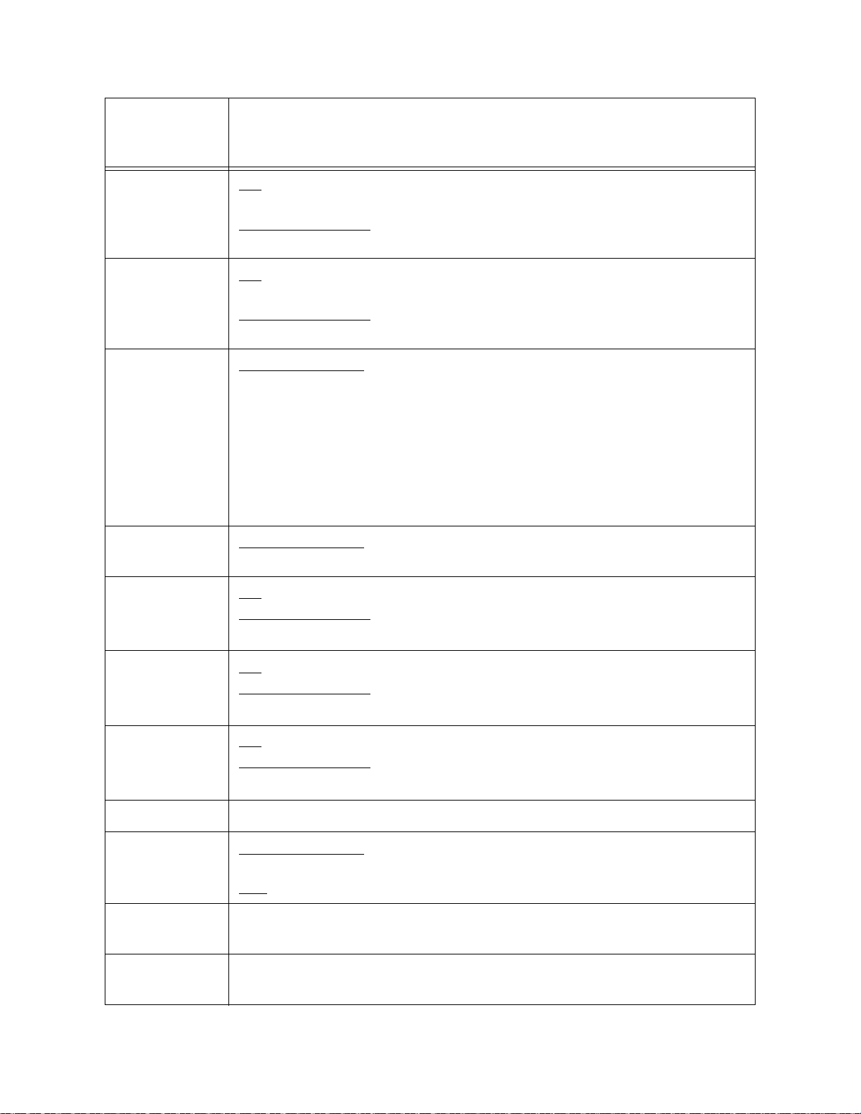
Maintenance
Mode
Menu Item
Table 15: Maintenance Mode Menu Items
Description
A.ZERO (page
93)
ID DISP (page
93)
ZERO.SUP
(page 94)
ZERO.FLW
(page 94)
ON: The SC-04 asks if you want to perform a fresh air adjustment at the end of the
startup sequence.
OFF (factory setting)
: The SC-04 does not ask if you want to perform a fresh air
adjustment at the end of the startup sequence.
ON
: User ID and Station ID screens appear in startup sequence. IDs can be
changed in Display Mode if DISP.SET in User Mode is also set to ON.
OFF (factory setting)
: User ID and Station ID screens do not appear in startup
sequence. IDs cannot be changed in Display Mode.
ON (factory setting)
: Not intended for field adjustment. The suppression values
are:
Cl
: 0.10 ppm
2
HCN: 0.5 ppm
NH
: 4 ppm
3
NO
: 0.30 ppm
2
PH
: 0.02 ppm
3
SO
: 0.20 ppm
2
ON (factory setting)
: Not intended for field adjustment.
ZSUP.DSP
(page 94)
ON
: Zero suppression item appears in User Mode.
OFF (factory setting)
: Zero suppression item does not appear in User Mode.
(Zero suppression item is always available in Maintenance Mode)
ZFLW.DSP
(page 94)
ON
: Zero follower item appears in User Mode.
OFF (factory setting)
: Zero follower item does not appear in User Mode.
(Zero follower item is always available in Maintenance Mode)
CYL.DISP
(page 95)
ON
: CYL SEL item appears in GAS CAL.
OFF (factory setting)
: CYL SEL item does not appear in GAS CAL.
(RKI Instruments, Inc. does not recommend adjusting this setting.)
DATE (page 95) Set the current date and time.
PASS-W (page
95)
ROM/SUM
ON (factory setting)
: Maintenance Mode is password-protected. Factory-set pass-
word is 0400.
OFF
: Maintenance Mode is not password-protected.
View the firmware information for the SC-04’s sensor board and main board.
(page 96)
M.DEF (page
Set all parameters back to their RKI factory settings.
97)
SC-0 4 Operator’s Manual Appendix A: Maintenance Mode • 87
Find Quality Products Online at: sales@GlobalTestSupply.com
www.GlobalTestSupply.com
Page 88

Maintenance
PASS-W set to OFF PASS-W set to ON
0000
PASS- W
BUMP
GAS CAL
Mode
Menu Item
Table 15: Maintenance Mode Menu Items
Description
START (page
97)
Press and release POWER MODE to begin the warmup sequence and enter Mea-
suring Mode.
Entering Maintenance Mode
WARNING: The SC-04 is not in operation as a gas detector while in Maintenance Mode.
1. Take the SC-04 to a non-hazardous location and turn it off if it is on.
2. Press and hold AIR, then press and hold POWER MODE. You will hear a beep after one
second. Continue to hold the buttons down.
3. When you hear a second beep, release the buttons.
4. The screen that appears depends on the setting of Maintenance Mode’s PA SS -W item.
If PASS-W is set to OFF, continue with Step 8.
If PASS-W is set to ON (factory setting), continue with Step 5.
5. If PAS S- W is set to ON in Maintenance Mode, a password screen appears and the first digit is
flashing. The factory-set password is 0400 but it can be changed.
6. Use AIR to select each password number then press POWER MODE to save it and move on
to the next number. To go back a number, press and hold AIR and POWER MODE for a few
seconds. To reverse the direction of change (ie. from increasing to decreasing or vice versa):
a. Press and hold AIR.
b. Immediately press POWER MODE and then release both buttons.
7. Continue to Step 6.
8. The GAS CAL item displays.
88 • Appendix A: Maintenance Mode SC- 04 Operator’s Manual
Find Quality Products Online at: sales@GlobalTestSupply.com
www.GlobalTestSupply.com
Page 89

9. Use AIR to move through the Maintenance Mode items.
Tips for Using Maintenance Mode
• To scroll from one item to the next, press and release AIR. To reverse the scrolling direction:
a. Press and hold AIR.
b. Immediately press POWER MODE and then release both buttons.
c. The scrolling direction returns to the original direction when you exit and reenter a menu.
• To skip an item when a question is asked, press and release AIR.
• To enter an item and to save any changes, press and release POWER MODE.
• To change a flashing parameter, press and release AIR. To reverse the direction of change (ie.
from increasing to decreasing or vice versa):
a. Press and hold AIR.
b. Immediately press POWER MODE and then release both buttons.
• To exit an entered item without saving a change, press and hold AIR and POWER MODE for a
few seconds.
Performing a Calibration (GAS CAL)
See page 46 for a description of the GAS CAL item.
Performing a Gas Test (GAS.TEST)
The GAS.TEST item allows you to apply gas to the instrument and see all alarm indications
except
though the buzzer sounds in the event of a real gas alarm condition while in Measuring Mode.
A gas test is not saved in logged data.
Preparing for a Gas Test
To perform a gas test on the SC-04, you need:
for the buzzer indication. There is no buzzer indication in the GAS.TEST menu even
• A calibration gas cylinder. The concentrations should be above the alarm condition you
want to check. Standard alarm points are listed on page 8.
• A 0.25 LPM fixed flow regulator
• Non-absorbent tubing
• Calibration cup
SC-0 4 Operator’s Manual Appendix A: Maintenance Mode • 89
Find Quality Products Online at: sales@GlobalTestSupply.com
www.GlobalTestSupply.com
Page 90

1. Install the calibration cup onto the SC-04. Be sure the calibration cup is installed in the correct
POWER
MODE
AIR
Front ViewSide View
GAS .TEST
SO2
0.00
GAS .TEST
ppm
SO2
0.00
BUZZ .OFF
ppm
direction and that it is pushed on all the way.
2. Use the tubing to connect the regulator to the inlet of the calibration cup (labeled “IN”).
Performing a Gas Test
1. While in Maintenance Mode, press AIR to scroll to GAS.TEST.
2. Press and release POWER MODE. The current gas reading displays. The bottom of the LCD
alternates between “GAS.TEST” and “BUZZ.OFF”.
3. For toxic gas cylinders, it is important to vent the regulator while installing it onto the
cylinder. Venting the regulator during installation helps prevent air from getting into the
cylinder and degrading the gas. Open the regulator by turning the knob counterclockwise and
install it onto the cylinder.
4. The instrument initiates alarm indications except
in the GAS.TEST menu even though the buzzer sounds in the event of a real gas alarm
condition.
5. Turn the regulator knob clockwise to close the regulator.
6. Unscrew the regulator from the calibration cylinder.
7. Remove the calibration cup from the SC-04.
for the buzzer. There is no buzzer indication
90 • Appendix A: Maintenance Mode SC- 04 Operator’s Manual
Find Quality Products Online at: sales@GlobalTestSupply.com
www.GlobalTestSupply.com
Page 91

8. Store the calibration kit in a safe and convenient place.
SEN .DATE
2019
11 .2
SO2
2019
1. 1
BATTERY
ESCAPE
AIR AIR
AIR
9. Press and release POWER MODE to return to the GAS.TEST item in Maintenance Mode.
10. See “Entering Measuring Mode (START)” on page 97 to enter Measuring Mode.
Sensor/Battery Replacement Date (SEN.DATE)
The SEN.DATE item allows you to keep track of when the sensor and the batteries were replaced.
1. While in Maintenance Mode, press AIR to scroll to SEN.DATE.
2. Press and release POWER MODE. The sensor replacement date displays.
3. Use AIR to scroll to the item whose replacement date you want to view or change.
4. To change the replacement date:
a. With the desired item displayed, press and release POWER MODE.
b. Press and release POWER MODE again to set the replacement date to the current date.
5. Use the AIR button to scroll to ESCAPE.
6. Press and release POWER MODE to return to the SEN.DATE item in Maintenance Mode.
7. See “Entering Measuring Mode (START)” on page 97 to enter Measuring Mode.
Performing a Bump Test (BUMP)
See “Performing a Bump Test (BUMP)” on page 42 for a description of the BUMP item.
SC-0 4 Operator’s Manual Appendix A: Maintenance Mode • 91
Find Quality Products Online at: sales@GlobalTestSupply.com
www.GlobalTestSupply.com
Page 92
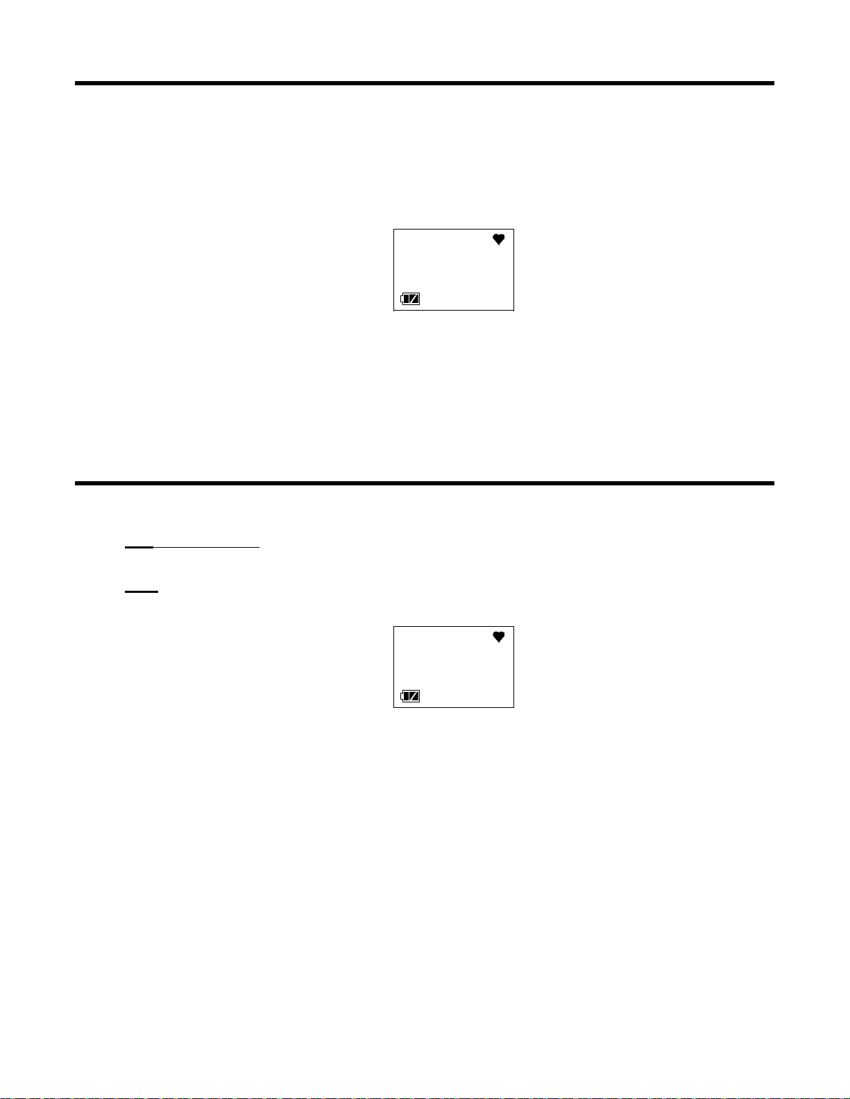
Setting Alarms to Latching or Self-Resetting (LATCH)
LATCH
D .ZERO
ON (factory setting): The SC-04 remains in alarm until the alarm condition passes and POWER
MODE is pressed.
OFF: The SC-04 automatically resets an alarm when the alarm condition passes.
1. While in Maintenance Mode, press AIR to scroll to LATCH.
2. Press and release POWER MODE. The current setting flashes.
3. Use AIR to display the desired setting.
4. Press and release POWER MODE to save the setting and return to the LATCH item in
Maintenance Mode.
5. See “Entering Measuring Mode (START)” on page 97 to enter Measuring Mode.
Turning the Demand Zero Function On/Off (D.ZERO)
ON (factory setting): You can manually perform a fresh air adjust in Measuring Mode by pressing
AIR.
OFF: You cannot manually perform a fresh air adjust in Measuring Mode.
1. While in Maintenance Mode, press AIR to scroll to D.ZERO.
2. Press and release POWER MODE. The current setting flashes.
3. Use AIR to display the desired setting.
4. Press and release POWER MODE to save the setting and return to the D.ZERO item in
Maintenance Mode.
5. See “Entering Measuring Mode (START)” on page 97 to enter Measuring Mode.
92 • Appendix A: Maintenance Mode SC- 04 Operator’s Manual
Find Quality Products Online at: sales@GlobalTestSupply.com
www.GlobalTestSupply.com
Page 93

Turning the Auto Zero Function On/Off (A.ZERO)
A .ZERO
ID DISP
ON: The SC-04 asks if you want to perform a fresh air adjustment at the end of the startup
sequence.
OFF (factory setting): The SC-04 does not ask if you want to perform a fresh air adjustment at the
end of the startup sequence.
1. While in Maintenance Mode, press AIR to scroll to A.ZERO.
2. Press and release POWER MODE. The current setting flashes.
3. Use AIR to display the desired setting.
4. Press and release POWER MODE to save the setting and return to the A.ZERO item in
Maintenance Mode.
5. See “Entering Measuring Mode (START)” on page 97 to enter Measuring Mode.
Turning the ID Display Function On/Off (ID DISP)
ON: The User ID and Station ID screens appear in the startup sequence. If DISP.SET in User
Mode is also set to ON, then the IDs can be changed in Display Mode.
OFF (factory setting): The User ID and Station ID screens do not appear in the startup sequence
and the IDs cannot be changed in Display Mode.
1. While in Maintenance Mode, press AIR to scroll to ID DISP.
2. Press and release POWER MODE. The current setting flashes.
3. Use AIR to display the desired setting.
4. Press and release POWER MODE to save the setting and return to the ID DISP item in
Maintenance Mode.
5. See “Entering Measuring Mode (START)” on page 97 to enter Measuring Mode.
SC-0 4 Operator’s Manual Appendix A: Maintenance Mode • 93
Find Quality Products Online at: sales@GlobalTestSupply.com
www.GlobalTestSupply.com
Page 94

Turning the Zero Suppression On/Off (ZERO.SUP)
The ZERO.SUP setting is not intended for field adjustment. The default setting is ON.
Sensor
Cl
2
HCN 0.5 ppm
NH
3
NO
2
PH
3
SO
2
Zero Suppression
Val ue
0.10 ppm
4 ppm
0.30 ppm
0.02 ppm
0.20 ppm
Turning the Zero Follower On/Off (ZERO.FLW)
The ZERO.FLW setting is not intended for field adjustment. The default setting is ON.
User Mode Zero Suppression (ZSUP.DSP)
ON: Zero suppression item appears in User Mode.
OFF (factory setting): Zero suppression item does not appear in User Mode. The zero suppression
item is always available in Maintenance Mode.
It is not normally necessary to have the zero suppression item appear in User Mode. Contact RKI
Instruments before turning this setting on.
User Mode Zero Follower (ZFLW.DSP)
ON: Zero follower item appears in User Mode.
OFF (factory setting): Zero follower item does not appear in User Mode. The zero follower item
is always available in Maintenance Mode.
It is not normally necessary to have the zero follower item appear in User Mode. Contact RKI
Instruments before turning this setting on.
94 • Appendix A: Maintenance Mode SC- 04 Operator’s Manual
Find Quality Products Online at: sales@GlobalTestSupply.com
www.GlobalTestSupply.com
Page 95

Cylinder Setting (CYL.DISP)
DATE
2020
4.21
10:40
PASS-W
ON: CYL SEL item appears in User and Maintenance Modes’ GAS CAL item.
OFF (factory setting): CYL SEL item does not appear in User and Maintenance Modes’ GAS
CAL item.
Setting the Date/Time (DATE)
1. From the main menu, place the cursor next to DATE.
2. Press and release POWER MODE. The date and time display with the year flashing.
3. Use AIR to display the desired year.
4. Press and release POWER MODE to save the setting. The month setting flashes.
5. Repeat Step 3 and Step 4 to enter the month, day, hours, and minutes settings. The date and
time are saved and the instrument returns to the DATE item in Maintenance Mode.
6. See “Entering Measuring Mode (START)” on page 97 to enter Measuring Mode.
Turning the Password On/Off (PASS-W)
ON (factory setting): The SC-04 prompts you for a password when you enter Maintenance Mode.
The factory-set password is 0400 but it can be changed.
OFF: No password is required to enter Maintenance Mode.
1. While in Maintenance Mode, press AIR to scroll to PASS -W.
2. Press and release POWER MODE. The current setting flashes.
3. Use AIR to display the desired setting.
SC-0 4 Operator’s Manual Appendix A: Maintenance Mode • 95
Find Quality Products Online at: sales@GlobalTestSupply.com
www.GlobalTestSupply.com
Page 96
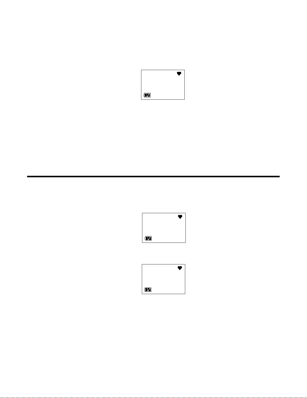
4. If you selected OFF, press and release POWER MODE to save the setting and return to the
0400
PASS- W
ROM/SUM
6180
72F8
ROM/SUM
PASS- W item in User Mode.
If you selected ON, continue with Step 5.
5. Press and release POWER MODE. The Set Password Screen appears. The current password
displays and the first digit flashes.
6. Use AIR to display a number from 0 to 9.
7. Press and release POWER MODE to enter the selection and advance to the next number. To
go back a number, press and hold AIR and POWER MODE for a few seconds.
8. Repeat Step 6 and Step 7 to select the remaining numbers. When you press and release
POWER MODE to enter the last number, the password is saved and the instrument returns to
the PASSWORD item in Maintenance Mode.
9. See “Entering Measuring Mode (START)” on page 97 to enter Measuring Mode.
Viewing the ROM/SUM (ROM/SUM)
The ROM/SUM screen shows the instrument’s firmware version and firmware checksum.
1. While in Maintenance Mode, press AIR to scroll to ROM/SUM.
2. Press and release POWER MODE. The screen shows the ROM/SUM. The ROM is the top
value and the SUM is the bottom value.
3. Press and release POWER MODE to return to the ROM/SUM item in Maintenance Mode.
4. See “Entering Measuring Mode (START)” on page 97 to enter Measuring Mode.
96 • Appendix A: Maintenance Mode SC- 04 Operator’s Manual
Find Quality Products Online at: sales@GlobalTestSupply.com
www.GlobalTestSupply.com
Page 97
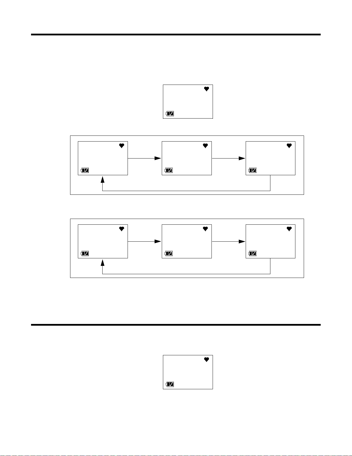
Performing a Default (M.DEF)
M .DEF
M .DEF YES .MODE
NO .AIR
SURE ? YES .MODE
NO .AIR
START
Performing a default operation in Maintenance Mode returns all parameters to their RKI factory
settings.
1. While in Maintenance Mode, press AIR to scroll to M.DEF.
2. Press and release POWER MODE.
3. Press and release POWER MODE to perform a default operation. The instrument asks if you
are sure you want to perform a default operation.
4. Press and release POWER MODE to perform a default operation. The instrument beeps twice
and returns to the M.DEF item in Maintenance Mode.
5. See “Entering Measuring Mode (START)” on page 97 to enter Measuring Mode.
Entering Measuring Mode (START)
1. While in Maintenance Mode, press AIR to scroll to START.
2. Press and release POWER MODE. The instrument begins its warmup sequence.
SC-0 4 Operator’s Manual Appendix A: Maintenance Mode • 97
Find Quality Products Online at: sales@GlobalTestSupply.com
www.GlobalTestSupply.com
Page 98

Appendix B: Gas Select Mode
0000
PASS- W
Overview
This appendix describes the SC-04 in Gas Select Mode. The SC-04 is factory-set to suit most
applications. Update settings in Gas Select Mode only if required for your specific application. A
description of the Gas Select Mode items is shown in Table 16 below.
Table 16: Gas Select Mode Menu Items
Menu Item (Page # of
Description)
SAVE-AP (page 99) Set the current alarm points as the default alarm points.
MAX.SPAN (page 100) ON: Maximum span screen appears after a successful calibration.
STEALTH (page 101) STEALTH ON
START (page 101) Enter Measuring Mode
Description
OFF (factory setting)
STEALTH OFF
normally.
This setting has no effect unless STEALTH is set to ON.
VIB ON
VIB OFF
: Vibrator activates for alarm conditions.
(factory setting): Vibrator does not activate in any situation.
: No maximum span screen appears.
: No backlight, LED, or buzzer operation.
(factory setting): Backlight, LED, and buzzer operate
Entering Gas Select Mode
WARNING: The SC-04 is not in operation as a gas detector while in Gas Select Mode.
1. Take the SC-04 to a non-hazardous location and turn it off if it is on.
2. Press and hold AIR, then press and hold POWER MODE. You will hear a beep after one
second. Continue to hold the buttons down.
3. You will hear a second beep. Continue to hold the buttons down.
4. When you hear a third beep, release the buttons.
5. A password screen appears and the first digit flashes. The password is 2014.
98 • Appendix B: Gas Select Mode S C- 04 Operator’s Manual
Find Quality Products Online at: sales@GlobalTestSupply.com
www.GlobalTestSupply.com
Page 99

6. Use AIR to select each password number then press POWER MODE to save it and move on
SAVE - AP
SAVE - AP
to the next number. To go back a number, press and hold AIR and POWER MODE for a few
seconds.
7. The SAVE-AP item displays.
8. Use AIR to move through the Gas Select Mode items.
Tips for Using Gas Select Mode
• To scroll from one item to the next, press and release AIR. To reverse the scrolling direction:
a. Press and hold AIR.
b. Immediately press POWER MODE and then release both buttons.
c. The scrolling direction returns to the original direction when you exit and reenter a menu.
• To skip an item when a question is asked, press and release AIR.
• To enter an item and to save any changes, press and release POWER MODE.
• To change a flashing parameter, press and release AIR. To reverse the direction of change (ie.
from increasing to decreasing or vice versa):
a. Press and hold AIR.
b. Immediately press POWER MODE and then release both buttons.
• To exit an entered item without saving a change, press and hold AIR and POWER MODE for a
few seconds.
Saving the Alarm Points (SAVE-AP)
Performing a SAVE-AP operation saves the current alarm setpoints.
Performing a DEF.ALMP operation in the ALARM-P User Mode menu sets the instrument’s
alarm points to those saved during the SAVE-AP operation (if performed).
Performing a SAVE-AP has no effect on an M.DEF in Maintenance Mode. An M.DEF operation
returns all instrument settings to the RKI default regardless of if a SAVE-AP operation was
performed.
1. While in Gas Select Mode, press AIR to scroll to SAVE-AP.
SC-0 4 Operator’s Manual Appendix B: Gas Select Mode • 99
Find Quality Products Online at: sales@GlobalTestSupply.com
www.GlobalTestSupply.com
Page 100

2. Press and release POWER MODE. The display cycles through the following screens.
SEL
SAVE - AP
SEL
YES .MODE
SEL
NO .AIR
MAX .SPAN
3. Press and release POWER MODE to save the current alarm point settings as the default.
4. The instrument returns to the SAVE-AP item in Gas Select Mode.
5. See “Exiting Gas Select Mode (START)” on page 101 to enter Measuring Mode.
Turning Calibration Max Span On/Off (MAX.SPAN)
ON: After a passed calibration, the SC-04 displays the response reading’s maximum adjustment.
A maximum span of 100 ppm indicates that the reading could have been adjusted up to 100 ppm.
If the maximum span value is close to the calibration value, the sensor should be replaced soon.
The upper limit on the maximum adjustment indicated is either twice the calibration value or full
scale, whichever is lower.
OFF (factory setting): There is no maximum span indication at the end of a calibration.
1. While in Gas Select Mode, press AIR to scroll to MAX.SPAN.
2. Press and release POWER MODE. The current setting flashes.
3. Use AIR to display the desired setting.
4. Press and release POWER MODE to save the setting and return to the MAX.SPAN item in
Gas Select Mode.
5. See “Exiting Gas Select Mode (START)” on page 101 to enter Measuring Mode.
100 • Appendix B: Gas Select Mode SC- 04 Operator’s Manual
Find Quality Products Online at: sales@GlobalTestSupply.com
www.GlobalTestSupply.com
 Loading...