

Page 1

72-2102-07
Beacon 200
Operator’s Manual
Part Number: 71-0364
Revision: A
Released: 12/11/17
www.rkiinstruments.com
Page 2

WARNING
Read and understand this instruction manual before operating
instrument. Improper use of the 72-2102-07 Beacon 200 could
result in bodily harm or death.
Periodic calibration and maintenance of the 72-2102-07 Beacon
200 is essential for proper operation and correct readings. Please
calibrate and maintain this 72-2102-07 Beacon 200 regularly!
Frequency of calibration depends upon the type of use you have
and the sensor types. Typical calibration frequencies for most
applications are between 3 and 6 months, but can be required
more often or less often based on your usage.
72-2102-07 Beacon 200 Operator’s Manual
Page 3

Product Warranty
RKI Instruments, Inc. warrants gas alarm equipment sold by us to be free
from defects in materials, workmanship, and performance for a period of
one year from date of shipment from RKI Instruments, Inc. Any parts found
defective within that period will be repaired or replaced, at our option, free
of charge. This warranty does not apply to those items, which by their
nature, are subject to deterioration or consumption in normal service, and
which must be cleaned, repaired, or replaced on a routine basis. Examples
of such items are as follows:
a) Absorbent cartridges d) Batteries
b) Pump diaphragms and valves e) Filter elements
c) Fuses
Warranty is voided by abuse including mechanical damage, alteration,
rough handling, or repair procedures not in accordance with the operator’s
manual. This warranty indicates the full extent of our liability, and we are
not responsible for removal or replacement costs, local repair costs,
transportation costs, or contingent expenses incurred without our prior
approval.
THIS WARRANTY IS EXPRESSLY IN LIEU OF ANY AND ALL OTHER
WARRANTIES AND REPRESENTATIONS, EXPRESSED OR IMPLIED,
AND ALL OTHER OBLIGATIONS OR LIABILITIES ON THE PART OF
RKI INSTRUMENTS, INC. INCLUDING BUT NOT LIMITED TO, THE
WARRANTY OF MERCHANTABILITY OR FITNESS FOR A
PARTICULAR PURPOSE. IN NO EVENT SHALL RKI INSTRUMENTS,
INC. BE LIABLE FOR INDIRECT, INCIDENTAL, OR CONSEQUENTIAL
LOSS OR DAMAGE OF ANY KIND CONNECTED WITH THE USE OF
ITS PRODUCTS OR FAILURE OF ITS PRODUCTS TO FUNCTION OR
OPERATE PROPERLY.
This warranty covers instruments and parts sold to users by authorized
distributors, dealers, and representatives as appointed by RKI Instruments,
Inc.
We do not assume indemnification for any accident or damage caused by
the operation of this gas monitor, and our warranty is limited to the
replacement of parts or our complete goods.
72-2102-07 Beacon 200 Operator’s Manual
Page 4

Table of Contents
Chapter 1: Introduction . . . . . . . . . . . . . . . . . . . . . . . . . . . . . . . . . . . . . . . . . . . . . . . . . 1
Overview . . . . . . . . . . . . . . . . . . . . . . . . . . . . . . . . . . . . . . . . . . . . . . . . . . . . . . . . 1
About the Beacon 200 Gas Monitor . . . . . . . . . . . . . . . . . . . . . . . . . . . . . . . . . . . 1
About this Manual . . . . . . . . . . . . . . . . . . . . . . . . . . . . . . . . . . . . . . . . . . . . . . . . . 2
Specifications . . . . . . . . . . . . . . . . . . . . . . . . . . . . . . . . . . . . . . . . . . . . . . . . . . . . 3
Chapter 2: Description . . . . . . . . . . . . . . . . . . . . . . . . . . . . . . . . . . . . . . . . . . . . . . . . . 4
Overview . . . . . . . . . . . . . . . . . . . . . . . . . . . . . . . . . . . . . . . . . . . . . . . . . . . . . . . . 4
External Description . . . . . . . . . . . . . . . . . . . . . . . . . . . . . . . . . . . . . . . . . . . . . . . 5
Internal Description . . . . . . . . . . . . . . . . . . . . . . . . . . . . . . . . . . . . . . . . . . . . . . . . 8
Chapter 3: Installation and Start Up. . . . . . . . . . . . . . . . . . . . . . . . . . . . . . . . . . . . . . 14
Overview . . . . . . . . . . . . . . . . . . . . . . . . . . . . . . . . . . . . . . . . . . . . . . . . . . . . . . . 14
Mounting the Beacon 200 . . . . . . . . . . . . . . . . . . . . . . . . . . . . . . . . . . . . . . . . . . 14
Wiring the Beacon 200 . . . . . . . . . . . . . . . . . . . . . . . . . . . . . . . . . . . . . . . . . . . . 17
Starting Up the Beacon 200 . . . . . . . . . . . . . . . . . . . . . . . . . . . . . . . . . . . . . . . . 23
Chapter 4: Operation . . . . . . . . . . . . . . . . . . . . . . . . . . . . . . . . . . . . . . . . . . . . . . . . . . 24
Overview . . . . . . . . . . . . . . . . . . . . . . . . . . . . . . . . . . . . . . . . . . . . . . . . . . . . . . . 24
Normal Operation . . . . . . . . . . . . . . . . . . . . . . . . . . . . . . . . . . . . . . . . . . . . . . . . 24
Recorder Output Operation. . . . . . . . . . . . . . . . . . . . . . . . . . . . . . . . . . . . . . . . . 25
Alarm Indications. . . . . . . . . . . . . . . . . . . . . . . . . . . . . . . . . . . . . . . . . . . . . . . . . 26
Viewing & Resetting Min/Max Readings . . . . . . . . . . . . . . . . . . . . . . . . . . . . . . . 31
Chapter 5: Channel Control and Setup Program . . . . . . . . . . . . . . . . . . . . . . . . . . . 32
Overview . . . . . . . . . . . . . . . . . . . . . . . . . . . . . . . . . . . . . . . . . . . . . . . . . . . . . . . 32
Enable/Disable Channel(s) Menu . . . . . . . . . . . . . . . . . . . . . . . . . . . . . . . . . . . . 33
Configure Channel Settings Menu . . . . . . . . . . . . . . . . . . . . . . . . . . . . . . . . . . . 34
View System Information Menu . . . . . . . . . . . . . . . . . . . . . . . . . . . . . . . . . . . . . 36
72-2102-07 Beacon 200 Operator’s Manual
Page 5

Chapter 6: Maintenance . . . . . . . . . . . . . . . . . . . . . . . . . . . . . . . . . . . . . . . . . . . . . . . 37
Overview . . . . . . . . . . . . . . . . . . . . . . . . . . . . . . . . . . . . . . . . . . . . . . . . . . . . . . . 37
Calibration Program . . . . . . . . . . . . . . . . . . . . . . . . . . . . . . . . . . . . . . . . . . . . . . 37
Adjusting Strobe/Horn Volume . . . . . . . . . . . . . . . . . . . . . . . . . . . . . . . . . . . . . . 43
Replacing Components of the Beacon 200. . . . . . . . . . . . . . . . . . . . . . . . . . . . . 45
Preventive Maintenance . . . . . . . . . . . . . . . . . . . . . . . . . . . . . . . . . . . . . . . . . . . 47
Troubleshooting . . . . . . . . . . . . . . . . . . . . . . . . . . . . . . . . . . . . . . . . . . . . . . . . . 49
Parts List . . . . . . . . . . . . . . . . . . . . . . . . . . . . . . . . . . . . . . . . . . . . . . . . . . . . . . . 52
72-2102-07 Beacon 200 Operator’s Manual
Page 6

Chapter 1: Introduction
Overview
This chapter briefly describes the 72-2102-07 Beacon 200. This chapter
also describes the 72-2102-07 Beacon 200 Operator’s Manual (this
document). Table 1 at the end of this chapter lists the specifications for the
72-2102-07 Beacon 200.
About the Beacon 200
The 72-2102-07 Beacon 200 is a fixed-mounted, continuous-monitoring
gas detection instrument. This gas monitor is capable of detecting gas at
two locations. It includes an 8 foot AC power cord and 2 H
heads each on a user-defined length of cable.
S detector
2
The Beacon 200 displays the current gas readings on an LCD display
which is visible through the window in the cover (front face) and provides a
4 - 20 mA signal which indicates the target gas reading for use by a
recording device or programmable controller. Three sets of relay contacts,
two controlled by the gas alarms and one by the fail alarm, rated at 115
VAC 10 amps are available for controlling devices such as lights or horns
or for controlling higher rated relays. The alarm 1 relay is factory wired to
the strobe/horn and is not available for field use.
Two instrument programs allow you to display and change channel and
calibration settings. They are the Channel Control & Setup Program and
the Calibration Program.
1 • 72-2102-07 Beacon 200 Operator’s Manual
Page 7

About this Manual
!
The Beacon 200 Gas Monitor Operator’s Manual uses the following
conventions for notes, cautions, and warnings.
NOTE: Describes additional or critical information.
CAUTION: Describes potential damage to equipment.
WARNING: Describes potential danger that can result in injury or
Caution: refer to accompanying documentation
death.
~ Vac (AC voltage)
Vdc (DC voltage)
72-2102-07 Beacon 200 Operator’s Manual • 2
Page 8

Specifications
Table 1 lists specifications for the 72-2102-07 Beacon 200.
Description Specification
Table 1: 72-2102-07 Beacon 200 Specifications
Input Power
Construction (housing) Fiberglass/polyester with lexan window (NEMA 4X)
Controller Dimensions 21.0 in. H x 8.5 in. W x 7.00 in. D
Weight 20 lbs.
Environmental Conditions • -20°C to 50°C (-4°F to 122°F) max. ambient
Relays • Relay contacts rated for 10A @ 115/220V~ resistive or10A @ 30V
User Controls • Reset switch
Detection Range 0 to 100 PPM (parts per million) H
Alarm 1 Setpoint
Alarm 2 Setpoint
Response Time 90% in 30 seconds
115/220V ~ ±10%, 50/60Hz, 0.5/0.3A
or
24 V +10% -8%, 0.6A
(533 mm H x 216 mm W x 178 mm D)
• Maximum humidity of 80% relative
resistive
• SPDT Form C
• Program buttons: ESCAPE, UP/YES, DOWN/NO, and ENTER
2
10 ppm
2
50 ppm
1
S
2
Accuracy ± 5% of reading or ± 2 ppm H
1
The AC voltage input is factory set. The standard input is 115 V~.
*
2
*
The alarm setpoints shown are factory settings but they can be changed in the Channel Control and Setup
Program.
S (whichever is greater)
2
WARNING: When using the Beacon 200, you must follow the
instructions and warnings in this manual to assure
proper and safe operation of the Beacon 200 and to
minimize the risk of personal injury. Be sure to maintain
and periodically calibrate the Bea con 200 as de scribed in
this manual.
3 • 72-2102-07 Beacon 200 Operator’s Manual
Page 9
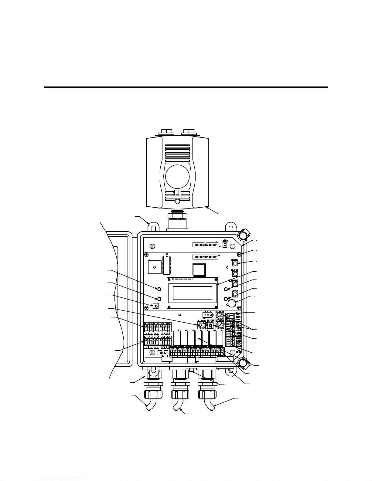
Chapter 2: Description
Figure 1. Beacon 200 Component Location
Buzz er
COM-FAIL
NON C C
CH2-A 1
NO NC CNONC C
COM-A1CH2-A2
NO NC C
CH1-A1
Main P CB
Display PC B
Program
Button (4)
AC In
Terminal
Stri p
Fuses, AC
Fail LED
Pilot LE D
NO NC C
COM-A2
Controller
Terminal Strip
Alarm Terminal S trip
Rela ys
Detector/
Transmitter
Terminal Strip,
Channel 1
Alarm
1LED
Display Contrast
Adjust Pot
Detector/
Transmitter
Terminal Strip,
Channel 2
Button
Repeater
Buzz er
Fuse, DC
MountingF oot, 4X
Horn/Strobe
AC PowerC ord
Reset
Switch
Conduit H ub ( 3X)
Power Switch
NON C CNO NC C
CH1-A2
Display
Alarm 2
LED
H2S Detector C able Channel 2 ( user-defined cablel ength)
H2S Det ector Cable Channel1
(user-defined cable length)
Overview
This chapter describes external and internal components of the Beacon
200.
72-2102-07 Beacon 200 Operator’s Manual • 4
Page 10

External Description
This section describes the housing and all external components of the
Beacon 200. For the purposes of this description, the housing door is
considered the front of the monitor.
Housing
The Beacon 200’s fiberglass housing is weather- and corrosion-resistant. It
is suitable for installation where general purpose equipment is in use. The
housing door is hinged on the left side and is secured by two latches on the
right side. The display screen and status lights are visible through windows
in the housing door. Four mounting feet are attached to the back of the
housing (one at each corner). The mounting feet allow you to install the
housing to a vertical surface. Three conduit hubs on the bottom of the
housing are for external wiring connections.
CAUTION: Only use the three facto ry installed condui t hubs on the bottom
of the housing for wire entry into the housing. Do not drill the
housing for any reason.
CAUTION: To avoid electrical interferen ce, do not r oute detec tor head a nd
power wiring thro ugh the same conduit hub.
Reset Switch
The reset switch is on the bottom of the housing. It is in front of the conduit
hubs. The reset switch serves three functions:
• Resets the alarm circuits for “latched” alarms after an alarm 1 or alarm 2
condition passes.
You can set each channel for latched or self-resetting alarms in the
Channel Control & Setup Program.
• Silences the buzzer during an alarm 1 or alarm 2 condition. You cannot
silence failure alarms.
• Displays and resets the minimum and maximum gas concentration
values.
Buzzer
The buzzer is on the bottom of the housing. It is on the far right. The buzzer
sounds audible alarms to warn you of gas alarms and instrument failures.
5 • 72-2102-07 Beacon 200 Operator’s Manual
Page 11
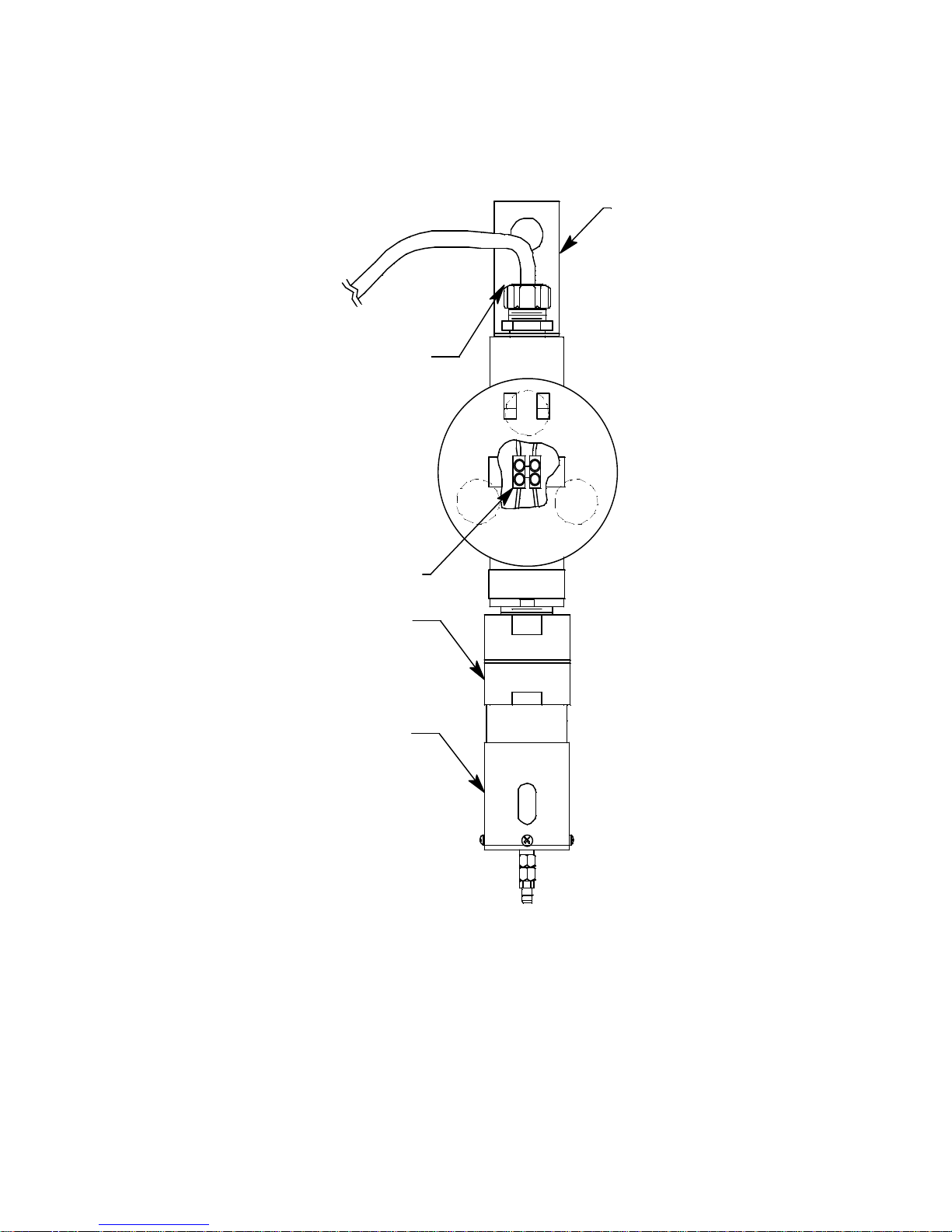
H2S Detector Junction Boxes and Cables
Cable Bushing
To Beacon 200
Mounting Bracket
H2S Detector
(FactoryWired )
Calibration Cup/
Splash Guard
Terminal Strip
Figure 2. H2S Junction Box Component Location
Each of the two H2S detectors consists of a junction box with a mounting
bracket, the detector, and the calibration cup/splash guard.
The two H
S detectors are factory wired through the left and middle cable
2
bushings of the Beacon 200 and has a user-defined length of cable for
remote installation. The mounting bracket at the top of each junction box is
used to mount the junction box. The junction box protects the detector
wiring connections. Three spacers installed on the back of the junction box
control the distance of the junction box from a mounting surface and
ensure that there is enough room to perform a calibration. A cover on the
front of the junction box allows access to the interior of the junction box.
72-2102-07 Beacon 200 Operator’s Manual • 6
Page 12
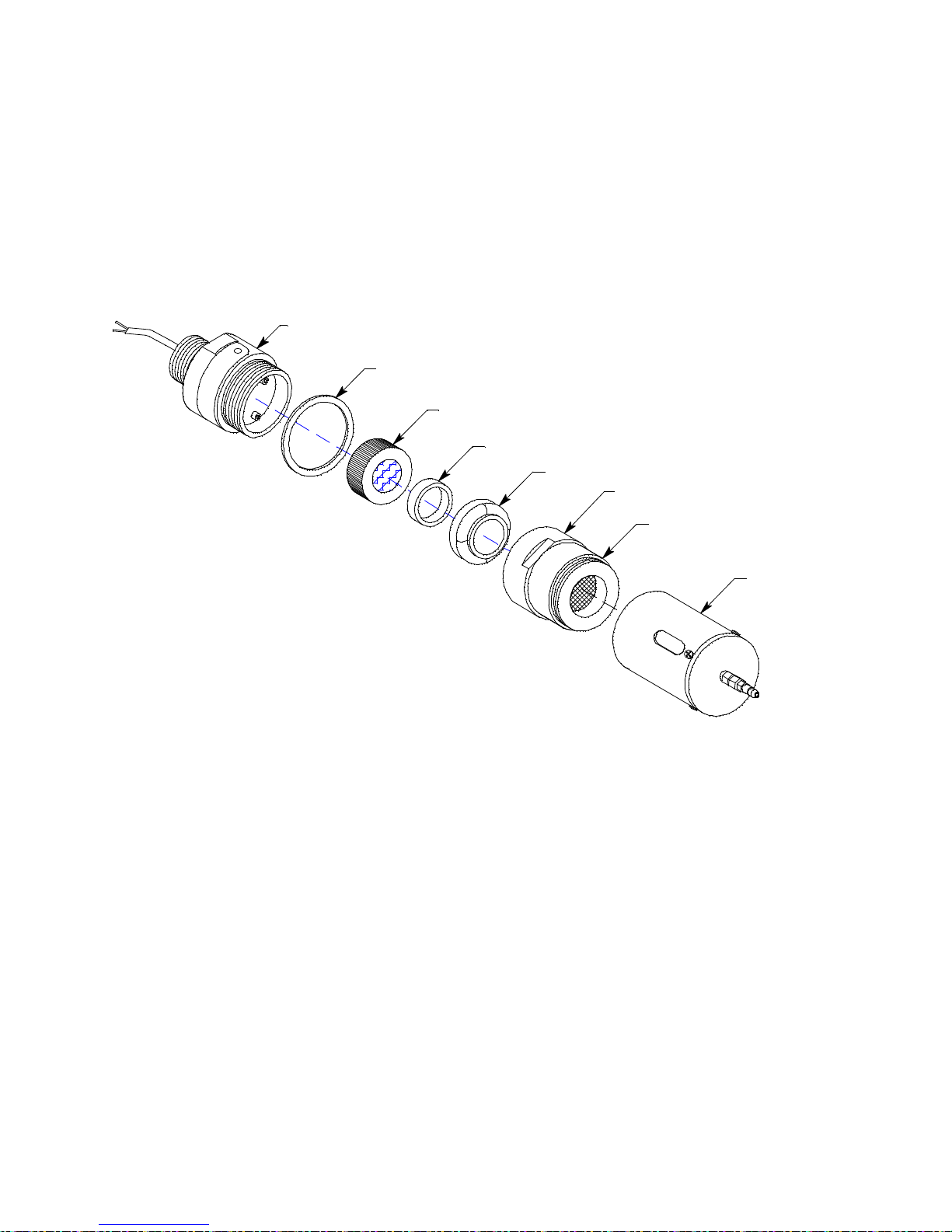
The detector housing body protects the sensing components within the
Cap Gasket
Detector HousingBody
Calibration Cup/
Splash Guard
Flame
Arrestor
Guard
Detector
HousingCap
H2S Plug-in Sensor
Rubber Boot
Spacer
Figure 3. H2S Detector Component Location
housing body. Use the removable cap near the bottom of the housing body
to access the sensor for maintenance or replacement. The cap protects the
sensor from damage and includes a flame arrestor which contains any
sparks which may occur within the detector housing body. A cap gasket
seals the interface between the housing body and cap. A flame arrestor
guard is permanently bonded to the cap.
The calibration cup/splash guard is screwed onto the bottom of the flame
arrestor guard.
The sensor is secured within the sensor housing by four pins. Through a
series of chemical and electrical reactions, the sensor produces an
electrical output that corresponds to the detection range of the detector. A
pre-amplifier, located between the sockets and two interconnect wires,
conditions the sensor’s signal before the signal reaches the controller. A
rubber boot and spacer are installed on the sensor face to ensure that the
sensor remains plugged into the detector housing body.
AC Power Cord
An 8 foot AC power cord is factory-wired through the right cable bushing of
the Beacon 200. One end of the cable is connected to the AC In terminal
strip.
7 • 72-2102-07 Beacon 200 Operator’s Manual
Page 13
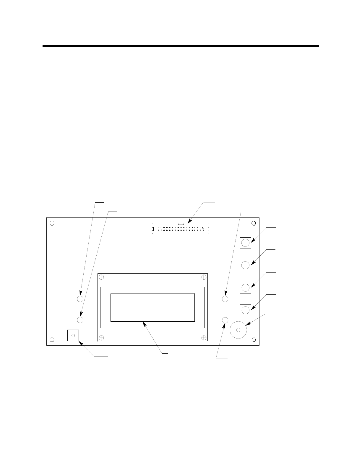
Internal Description
J1
UP/YES Button
ENTE R Button
DOWN/NO Button
Display Cable Connector
PILOT Light
FAIL Light
Displ ay Scree n
Button Repe ater
Buzzer
ALARM 2 Li gh t
ESCAPE Bu t to n
ALARM 1 Li gh t
Display Contrast
Adjust Pot
Figure 4. Display Board Component Location
This section describes the internal components of the Beacon 200. See
Figure 1 on page 4 for a view of the internal components.
Display Printed Circuit Board (PCB)
The display PCB is mounted to the power supply mounting plate which is in
turn mounted to the main PCB. The power supply mounting plate and main
PCB are described below. The display PCB includes the display, the status
lights, and the program buttons.
Display
The display simultaneously indicates the channel number, current gas
reading, measuring unit, and target gas of all active channels.
The display also indicates messages, settings, and other data when you
are operating the instrument programs.
72-2102-07 Beacon 200 Operator’s Manual • 8
Page 14

Status Lights
The Beacon 200 includes four status lights that indicate the current status
of the monitor. The status lights are to the left and right of the display (see
Figure 4).
• Pilot Light. The pilot light is on when the Beacon 200 is receiving
incoming power.
• Fail Light. The fail light turns on when the Beacon 200 is experiencing
a fail condition. A fail condition can be caused by a failure within the
Beacon 200 or detector head wired to the Beacon 200. See “Chapter 6:
Maintenance” on page 37 for instructions to respond to a fail condition.
• Alarm 1 Light. The alarm 1 light is on when the Beacon 200 is
experiencing an alarm 1 gas condition.
• Alarm 2 Light. The alarm 2 light is on when the Beacon 200 is
experiencing an alarm 2 gas condition.
Program Buttons
The Beacon 200 includes four program buttons that allow you to enter the
instrument programs, navigate through the programs, update instrument
and channel settings, and save changes to the program settings. When a
program button is pressed, a buzzer located on the display PCB beeps.
The program buttons are near the right edge of the display PCB (see
Figure 4).
Table 2: Beacon 200 Program Button Functions
Button Function
ESCAPE • Moves backward through the program menus
• Cancels changes you make in the program menus
• Enters the Channel Control and Setup program (press with the ENTER button)
UP/YES • Accepts the displayed setting and proceeds to the next setting
• Changes the displayed setting
• Enters the Calibration program (press with the ENTER button)
DOWN/NO • Allows you to update the displayed setting
• Changes the displayed setting
ENTER • Saves changes you make in the programs
• Enters the Channel Control and Setup program (press with ESCAPE button)
• Enters the Calibration program (press with the UP/YES button)
9 • 72-2102-07 Beacon 200 Operator’s Manual
Page 15

Main PCB
The main PCB is mounted inside the housing. The power supply mounting
plate is mounted to the main PCB with four standoffs and the display PCB
is mounted to the power supply mounting plate with four standoffs. The
main PCB includes the terminal strips, relays, fuses, and power switch.
Terminal Strips
The Beacon 200 includes four terminal strips for external wiring
connections. See “Wiring the Beacon 200” on page 17 for detailed wiring
procedures.
• Detector/Transmitter Terminal Strips. Two detector/transmitter
terminal strips are located near the bottom left corner of the main circuit
board (see Figure 1). These two 9-point terminal strips facilitate wiring
connections to the detectors. Only one detector head at a time may be
wired per channel. The top terminal strip is for channel 1 and the bottom
terminal strip is for channel 2. The H2S detectors are factory wired to
these terminal strips.
• Alarm Terminal Strip. The alarm terminal strip is located along the
bottom edge of the main circuit board (see Figure 1). This 21-point
terminal strips facilitates wiring connections to external alarm devices
(horn, strobe, etc.). Terminals are provided for individual channels as
well as common alarm relay contacts. The horn/strobe is factory wired
to this terminal strip.
• Controller Terminal Strip. The 10-point controller terminal strip is near
the lower right edge of the main circuit board (see Figure 1). The
controller terminal strip facilitates various internal and external wiring
connections. Table 3 lists the function of each terminal.
72-2102-07 Beacon 200 Operator’s Manual • 10
Page 16

Table 3: Terminal Assignments for the Controller Terminal Strip
Terminal Connects to:
BAT -
BAT +
+ CH1 OUT + connection of 4 - 20 mA output, channel 1
- CH 1 OUT - connection of 4 - 20 mA output, channel 1
+ CH2 OUT + connection of 4 - 20 mA output, channel 2
- CH2 OUT - connection of 4 - 20 mA output, channel 2
RESET (2) Reset switch (factory-wired)
BUZ-/BUZ+ Internal buzzer (factory-wired)
1 If DC power is used as the primary power source, do not make wiring connections to the AC terminal strip.
- connection from 24 VDC power source
+ connection from 24 VDC power source
1
(or 24 V backup battery)
1
(or 24 V backup battery)
• AC In Terminal Strip. The AC In terminal strip is a 3-point terminal strip
located above the controller terminal strip (see Figure 1). It facilitates
wiring from the AC power source. The 8 foot AC power cord is factory
wired to this terminal strip. Table 4 lists the function of each terminal.
Table 4: Terminal Assignments for the AC In Terminal Strip
Terminal Connects to:
LINE Hot wire from AC power source.
NEUT Neutral wire from AC power source.
GND Earth ground
Relays
The Beacon 200 includes four channel relays (two per channel) and three
common relays. Both sets of relays are single-pole, double-throw (SPDT)
and are rated for 10 amps at 250 VAC (resistive).
NOTE: You can select normally energized (NE) or normally de-energized
(NDE) settings for each channel in the Channel Control and Setup
program. This section describes the default setting: normally deenergized.
The alarm 1 and alarm 2 common relays are factory-set as NDE
and the fail common relay is factory-set as NE. The alarm 1, alarm
2, and fail common relays’ NE/NDE settings are not useradjustable.
11 • 72-2102-07 Beacon 200 Operator’s Manual
Page 17
• Channel relays. The four channel relays are above the alarm terminal
K1 K2 K3
Common Alarm 1
Common Alarm 2
Common Fail
K5 K6 K7
K4
Channel 2 , Ala rm 2
Channel 2 , Ala rm 1
Channel 1 , Ala rm 2
Channel 1 , Ala rm 1
Figure 5. Beacon 200 Channel Relay Allocation
strip (see Figure 1). These relays are dedicated to specific channels
and alarm levels.
For example, the channel 1, alarm 1 relay energizes if channel 1
recognizes an alarm 1 condition. Figure 4 below illustrates the
allocation of the channel relays.
NOTE: The alarm 2 channel relays may be set to operate as individual
channel fail relays. See “Configure Channel Settings Menu” on
page 34 for instructions.
• Common relays. The three common relays, alarm 1, alarm 2, and fail,
are to the left of the controller terminal strip (see Figure 1). These relays
are common for both channels.
For example, the alarm 1 common relay energizes if either channel 1 or
channel 2 recognizes an alarm 1 condition. The common alarm 1 relay
is factory wired to the strobe/horn and is not available for customer use.
Fuses
There are three fuses that are used in the Beacon 200. Two of them are AC
fuses and one of them is a DC fuse.
• AC Fuses. The two fuses located directly to the left of the controller
terminal strip are the AC fuses. They cut off the incoming AC power in
the event of a short circuit or other electrical fault which causes a high
current draw in the Beacon 200. They are housed in vertical fuse
holders and are held in the holder by a quarter turn cover. They are
labelled as F2 (top fuse) and F3 (bottom fuse) on the PCB silk-screen
and are rated at 3 A, 250 V.
• DC Fuse. The fuse located to the left of the power switch is the DC
fuse. It cuts off incoming DC power in the event of a short circuit or
72-2102-07 Beacon 200 Operator’s Manual • 12
Page 18

other electrical fault which causes a high current draw in the Beacon
200. It is also housed in a vertical fuse holder and is held in the holder
by a quarter turn cover. It is labelled as F1 on the PCB silk-screen and
is rated at 6A, 250 V.
Power Switch
The power switch is located above the relays and to the left of the DC fuses
(see Figure 1). The power switch turns the incoming AC power source on
and off at the Beacon 200. When the switch is up, the power switch is on.
NOTE: The DC power input has no on/off switch and is not affected by the
position of this switch.
Power Supply
The power supply is mounted to the power supply mounting plate which is
located behind the display PCB. The power supply mounting plate is
mounted to the main PCB with four standoffs. The power supply receives
the AC input from the external power source and converts it to a DC
voltage that is usable by the Beacon 200 circuitry.
13 • 72-2102-07 Beacon 200 Operator’s Manual
Page 19

Chapter 3: Installation and Start Up
Overview
This chapter describes procedures to mount the Beacon 200, make wiring
connections to the monitor, and start up the monitor.
WARNING: Perform all installation and start-up procedures in a
“fresh air” environment (known to be free of combustible
gas, toxic gas, and of normal oxygen content). The
Beacon 200 is not in operation as a gas monitoring
system until the start-up procedure is complete.
Mounting the Beacon 200
Perform the following procedure to install the Beacon 200 at the mounting
site.
72-2102-07 Beacon 200 Operator’s Manual • 14
Page 20

Mounting
Feet, 4X
8.0 Max
Ø .31 x .50 slot, 4X
RESET
Buzzer
.41
3/4 Conduit
Hubs ( 3X)
3/4 Cable
Bushings (2X)
FAIL
PILOT
Reset
Switch
7.00
6.45
AL AR M 2
AL AR M 1
4.83
8.5 0
6.00
10.50
10. 94
BEACON 200
GAS MON ITOR
Figure 6. Beacon 200 Outline and Mounting Dimensions
1. Select the mounting site. When you select the mounting site consider
the following factors:
• Is an AC or DC power source available?
• Is there enough room to open the housing door and make wiring
connections through the conduit hubs at the bottom of the housing?
• Are the display screen and status lights visible?
15 • 72-2102-07 Beacon 200 Operator’s Manual
Page 21

2. Close and latch the housing door.
Figure 7. H2S Detector Outline and Mounting Dimensions
Det ector Cable
Channel 2
.75
Ø.75
14.2 Max
To Middl e
Cable
Bushing
1.50
Detector Cable
Channe l 1
To Lef t
Cable
Bushing
3. Position the monitor on a vertical surface at eye level (4 1/2 to 5 feet
from the floor).
4. The Beacon 200 is shipped with the mounting feet positioned behind
the housing. Loosen the screws that secure the feet to the housing,
rotate the feet to their mounting position (as shown in Figure 6), then
tighten the screws.
5. Insert 1/4 in. or 5/16 in. screws through the slots in the mounting feet at
each corner of the housing to secure the housing to the mounting
surface (see Figure 6).
6. Hang each H2S detector junction box using the mounting bracket.
Ensure that the detectors are facing down.
72-2102-07 Beacon 200 Operator’s Manual • 16
Page 22

Wiring the Beacon 200
Figure 8. Beacon 200 Factory Wiring Diagram
Strobe / H orn
To P1
To P2
AC
Power
Cord
BAT -
Main P CB
Po wer
Su pply
CH2
OUT
RESET
+S +
LELOXYGENAMP/PREAMP
NO N C C
BUZ +
+
CH1
OUT
+
RESET
COM- A1CH2- A2CH 2-A1
NONC C N ON C CN ON C C
Channel 2
Channel 1
BlackRed
+S +
OXYGENAMP/PREAMP LEL
BlackRed
Bu zzer
BUZ
+V
V+AD J
L(AC)
N(AC)
G(AC)
COM
COM
GND
NEUT
LINE
COM- FAILCOM- A2
NO NC C
Detector Wiring
RWG B
+V
Detector
Cabl e
Conduit Hub s
NOTUSED NOT USED
Detector
Cabl e
RWG B
NO NC C
Reset Switch
CH1- A2
Alarm Relay Wiring
NO N C C
CH1-A1
BAT +
The detector leads, junction box connections, and strobe/horn wiring are all
factory wired.
17 • 72-2102-07 Beacon 200 Operator’s Manual
Page 23

WARNING: Make all connections to the Beacon 200 before you
connect the DC power source. Before you make any
wiring adjustments, always verify that all power sources
are not live.
Routing Wiring Into the Beacon 200 Housing
Wiring must be brought into the housing through one of the three factoryinstalled conduit hubs on the bottom of the housing.
Do not drill into the Beacon 200 housing for any reason. Drilling the Beacon
200 housing and routing wiring through holes not factory drilled will void the
warranty and could result in:
• Damage to internal components from the drilling process.
• Moisture damage to internal components from poorly sealed holes.
• Unpredictable Beacon 200 behavior due to EMI/RFI interference
caused by wires routed across the PCBs.
• Possible shorting of Beacon 200 components due to wires routed
across the PCBs.
Connecting the AC Power Source
NOTE: If you are using DC power as the primary power source, go to the
next section, “Connecting the DC Power Source.”
The 8 foot AC power cord is routed through the right-hand cable bushing
on the bottom of the housing and is factory wired to the AC In terminal strip.
Additional wiring is not necessary.
Connecting the DC Power Source
WARNING: V erify that the power source is unplugged or turned off at
the power source end before you continue with this
procedure.
DC power may be used as a primary power source. It may also be used as
a backup power source with a 24 VDC battery if AC power is the primary
power source. If DC power is the primary power source, DO NOT connect
AC power.
1. Turn off or unplug all incoming power to the Beacon 200 at the power
source end.
2. Open the housing door, then place the power switch in the OFF
position. Locate the DC power terminals on the controller terminal strip
72-2102-07 Beacon 200 Operator’s Manual • 18
Page 24

(see Figure 1). They are labelled BAT - and BAT +
+
24 VDC ± 2.5 VDC
BAT
BAT +
Controller Terminal Strip
Figure 9. DC Power Wiring
3. Install an appropriately rated cable bushing or conduit to one of the
unused conduit hubs on the bottom of the Beacon 200 housing.
CAUTION: Only use the three facto ry installed condui t hubs on the bottom
of the housing for wire entry into the housing. Do not drill the
housing for any reason. See “Routing Wiring Into the Beacon
200 Housing” on page 18 for more information.
4. Guide a DC power cord or wires through the selected conduit hub.
CAUTION: Do not route power and det ector head wiring through the same
conduit hub. The p ower wiring may disrupt the transmi ssi on of
the detector head signal to the monitor.
CAUTION: When a batter y is used as backup power, the Beacon 200
trickle charges the battery. Do not use a non-rechargeable
battery as backup power. Use RKI backup battery 49-8102RK
or an appropriately rate d re cha rg ea bl e le ad acid type battery.
5. Connect the DC wires to the controller terminal strip as shown in
Figure 7.
NOTE: If a 24 VDC battery is used as a backup power source, as long as
AC power is on the Beacon 200 will keep a trickle charge on the
battery to maintain its charge. If AC power is interrupted, the
Beacon 200 will operate from the DC backup battery until the
battery voltage drops to 21.5 volts or less, or until AC power is
restored. Battery recharge time will vary depending on how much
the battery was drained.
19 • 72-2102-07 Beacon 200 Operator’s Manual
Page 25

Connecting External Alarms
CNCNO
CH 1-A1
Beacon 200 Alarm
Terminal Strip
(-) N
External
Power
Source
(+) H
Ex te rn al Alar m D ev i ce
Figure 10. Typical External Alarm Wiring, Single Device
Perform the following procedure to connect external alarm devices to the
Beacon 200. The common alarm 1 terminals are factory wired and are not
available for field use.
NOTE: The alarm terminal strip includes terminals for channel alarms
and common alarms. Channel alarms are activated by one
particular channel. Common alarms are activated by either of the
two channels.The example used in this procedure describes
connecting an external alarm device to one of the channel alarm
terminals: the channel 1, alarm 1 terminals.
1. Turn off or unplug all incoming power to the Beacon 200 at the power
source end.
2. Open the housing door, then place the power switch in the OFF
position. Locate the alarm terminal strip (see Figure 1).
3. Guide the wiring of the external alarm device through the cable bushing
on the right-most conduit hub on the bottom of the Beacon 200 housing.
The power wiring should already be installed through this cable
bushing.
CAUTION: Only use the three facto ry installed condui t hubs on the bottom
of the housing for wire entry into the housing. Do not drill the
housing for any reason. See “Routing Wiring Into the Beacon
200 Housing” on page 18 for more information.
4. Connect the leads from the external alarm device and power to the
alarm terminals as shown in Figure 10.
72-2102-07 Beacon 200 Operator’s Manual • 20
Page 26

5. Repeat steps 4 and 5 for additional external alarm devices.
NO NC C NO NC C NO NC CNO NC CNO NC C
COM-A1 COM-A2 COM-FAILCH1-A 2 CH2-A1 CH2-A2
Alarm Devices
Alarm
Device
Power
Alarm
Terminal Strip
NO NC C
NO NC C
CH1-A 1
Contact Rating of 10 Amps at 115/220 V~ Resistive or
10A @ 30V Resistive for Each Set of Alarm RelayContacts.
Figure 11. Typical External Alarm Wiring, Multiple Devices
Connecting a Recorder
Perform the following procedure to connect an analog recording device to
the Beacon 200. The output at the recorder output terminals is a 4 - 20 mA
signal that is proportional to the detection range of the applicable detector
head.
1. Turn off or unplug all incoming power to the Beacon 200 at the power
source end.
2. Open the housing door, then place the power switch in the OFF
position. Locate the recorder output terminals on the controller terminal
strip (see Figure 1).
21 • 72-2102-07 Beacon 200 Operator’s Manual
Page 27

3. Guide the wiring from the recording device through the cable bushing
+
+
CH2
OUT
CH1
OUT
+
RecordingDevice#2,
1Kohm Max
Impedance
RecordingDevice#1,
1Kohm Max
Impedance
+
Figure 12. Recorder Output Wiring
on the right-most conduit hub on the bottom of the Beacon 200 housing.
The power wiring should already be installed through this cable
bushing.
CAUTION: Only use the three facto ry installed condui t hubs on the bottom
of the housing for wire entry into the housing. Do not drill the
housing for any reason. See “Routing Wiring Into the Beacon
200 Housing” on page 18 for more information.
4. Connect the wires from the recording device to the recorder output
terminals as shown in Figure 12.
72-2102-07 Beacon 200 Operator’s Manual • 22
Page 28

Starting Up the Beacon 200
Perform the following procedure to place the Beacon 200 into normal
operation.
1. Complete the mounting and wiring procedures described earlier in this
chapter.
2. Verify that all wiring connections are correct and secure and that the
Beacon 200’s power switch is in the OFF position.
3. Plug in or turn on the incoming power source (AC or DC) at the power
source end.
4. Place the Beacon 200’s power switch in the ON position. RKI
INSTRUMENTS BEACON 200 appears on the display for a few
seconds, then WARMING UP appears for each active channel. The
warm-up period will last for one minute.
NOTE: To prevent unwanted alarms during warm up, the alarm circuits
are not active while the WARMING UP message is displayed.
5. Verify that the PILOT light is on. If the PILOT light is not on, see
“Troubleshooting” on page 49.
6. The H2S detectors will begin operating once power is introduced to the
Beacon 200.
23 • 72-2102-07 Beacon 200 Operator’s Manual
Page 29

Chapter 4: Operation
1: 0 ppm H2S
2: 0 ppm H2S
Overview
This chapter describes the Beacon 200 in normal operation. This chapter
also describes the Beacon 200 in alarm 1, alarm 2, and fail conditions and
suggests responses to these conditions.
Normal Operation
Normal operation is defined as follows:
• The start-up procedure is complete.
• The Beacon 200 is not indicating an alarm 1, alarm 2, or fail condition.
• The Beacon 200 is not running the Channel Control & Setup or
Calibration Programs.
During normal operation, the Beacon 200 simultaneously displays the
current gas reading, unit of measure, and target gas for each active
channel.
The PILOT light is on during normal operation indicating that the Beacon
200 is receiving incoming power.
72-2102-07 Beacon 200 Operator’s Manual • 24
Page 30

Recorder Output Operation
The output at the recorder output terminals is a 4 - 20 mA signal for each
active channel that is proportional to the detection range of the channel. A
channel that is set as CHANNEL NOT USED or CHANNEL DISABLED in
the Channel Control & Setup Program (see “Chapter 5: Channel Control
and Setup Program” on page 32) has an output of 0 mA.
There are several special circumstances where the recorder output will
behave as follows:
• When a channel is in WARMUP after the Beacon 200 is turned on, the
recorder output will be at 4 mA.
• If the Beacon 200 is being powered by a battery and is in low battery
alarm, the recorder output for each channel will be 0 mA.
• When a channel is added or a channel type changed, the display will
indicate NEEDS CALIBRATION for that channel when the Beacon 200
is first turned on and will continue to indicate this until the channel is
calibrated. In this situation, the recorder output will be at 3.2 mA until
the channel is calibrated.
• If a channel goes into a fail condition, the recorder output will be 0 mA.
• If you enter any of the instrument programs, such as the Calibration
Program, the recorder output will hold at the value it was at when you
entered the program was entered until you return to normal operation.
25 • 72-2102-07 Beacon 200 Operator’s Manual
Page 31

Alarm Indications
This section describes the Beacon 200 in alarm 1, alarm 2, and fail
conditions and suggests response to these conditions. Table 5 below lists
the alarm indications for each condition.
NOTE: The Beacon 200 includes alarm on and alarm off delay settings for
each channel and level of gas alarm. The alarm indications
described in this section operate according to the factory set delay
settings. See “Configure Channel Settings Menu” on page 34 for
all the factory settings.
Table 5: Visual and Audible Alarm Indications
Condition Cause Visual Indication(s)
Alarm 1
Alarm 2
Fail • Disconnected or misconnected
Low Battery
*1If the Beacon 200 is in both an alarm 1 and an alarm 2 condition, both alarm lights are on and the display
*
1
1
alternates between the gas reading and the ALARM-1 ALARM-2 messa ge.
2
If DC power is use d as primary or backup power source.
Increasing gas reading at or above the
alarm 1 setpoint
Increasing gas reading at or above the
alarm 2 setpoint
detector wiring
• Display reading below -10% of full
scale or lower
• Defective components
2
No AC power and DC power source
(primary or backup) less than 21.5 volts.
• ALARM 1 light is on
• Gas reading flashes and
alternates with ALARM-1
message
• Strobe/horn turns on
• ALARM 2 light is on
• Gas reading flashes and
alternates with ALARM-2
message
• FAIL light is on
• FAIL message flashes in
place of gas reading
• FAIL light is on
• SUPPLY VOLTAGE IS TOO
LOW LOW POWER
STANDBY message and
actual voltage of incoming
DC power
Audible
Indication
Pulsing tone
Pulsing tone
Steady tone
None
72-2102-07 Beacon 200 Operator’s Manual • 26
Page 32

NOTE: You can select normally energized (NE) or normally de-energized
(NDE) channel relay settings in the Channel Control & Setup
menu. The following sections describe the default setting for the
channel relays which is NDE.
Common alarm 1 and alarm 2 relays are factory-set as NDE, and
the common fail relay is factory set as NE. The common relays’
NE/NDE settings are not user-adjustable.
Alarm 1 Condition
This section describes the audible and visual indications for an alarm 1
condition and suggests response to an alarm 1 condition.
Alarm 1 Condition Indications
When the gas reading of an active channel reaches the alarm 1 setpoint,
the Beacon 200 senses an alarm 1 condition. The Beacon 200 alerts you to
an alarm 1 condition as follows:
• The ALARM 1 light turns on.
• The gas reading in alarm 1 condition flashes and alternates with the
ALARM-1 message.
• The buzzer sounds a Pulsing tone.
• The common alarm 1 relay energizes and the strobe/horn activates.
• The applicable alarm 1 channel relay energizes.
Responding to an Alarm 1 Condition
This section suggests response to an alarm 1 condition.
1. Follow your established procedure for a low level H
S condition.
2
2. Alarms are latching. After the gas reading falls below the alarm 1
setpoint, press the reset switch to reset the alarm 1 circuit. Resetting
the alarm 1 circuit silences the buzzer, turns off the ALARM 1 light,
resets the channel display, de-energizes the common and channel
alarm 1 relays, and turns off the strobe/horn.
NOTE: To silence the buzzer while in an alarm 1 condition, press the
reset switch.
You cannot de-energize the alarm 1 relays and consequently the
strobe/horn until the gas reading falls below the alarm 1 setpoint.
27 • 72-2102-07 Beacon 200 Operator’s Manual
Page 33

Alarm 2 Condition
This section describes the audible and visual indications for an alarm 2
condition and suggests response to an alarm 2 condition.
Alarm 2 Condition Indications
When the gas reading of an active channel reaches the alarm 2 setpoint,
the Beacon 200 senses an alarm 2 condition. The Beacon 200 alerts you to
an alarm 2 condition as follows:
• The ALARM 2 light turns on.
• The gas reading in alarm 2 condition continues to flash and alternates
with the ALARM-2 messages.
• The buzzer sounds a Pulsing tone.
• The common alarm 2 relay energizes.
• The applicable alarm 2 channel relay energizes.
Responding to an Alarm 2 Condition
This section suggests response to an alarm 2 condition.
1. Follow your established procedure for a high level H2S condition.
2. Alarms are latching. After the gas reading falls below the alarm 2
setpoint, press the reset switch to reset the alarm circuit. Resetting the
alarm circuit turns off the ALARM 2 light, and de-energizes the common
and channel alarm 2 relays.
NOTE: To silence the buzzer while in an alarm 2 condition, press the
reset switch.
You cannot de-energize the alarm 2 relays until the gas reading
falls below the alarm 2 setpoint.
Fail Condition
This section describes the audible and visual indications for a fail condition
and suggests response to a fail condition.
Fail Condition Indications
The Beacon 200 senses a fail condition for any of the following:
• The detector head wiring to the Beacon 200 is disconnected or
incorrectly connected.
• The detector head’s detector is disconnected or incorrectly connected.
72-2102-07 Beacon 200 Operator’s Manual • 28
Page 34

• The display reading is -10% of full scale or lower.
• The Beacon 200 or detector head is malfunctioning.
When the Beacon 200 senses a fail condition, it alerts you as follows:
• The FAIL light turns on.
• The gas reading for the failing channel is replaced by the FAIL
message.
• The buzzer sounds a steady tone.
• The common fail relay de-energizes.
NOTE: If you elected to use the channel’s alarm 2 relay as an individual
fail relay in the Channel Control & Setup menu, the relay deenergizes in a fail condition. See “Chapter 5: Channel Control and
Setup Program” on page 32 for a description of this setting.
Responding to a Fail Condition
This section suggests response to a fail condition.
1. Verify that the detector head wiring to the Beacon 200 is correctly and
securely connected.
2. Verify that the detector head’s detector is correctly and securely
connected.
3. See the troubleshooting guide in the detector head instruction manual.
Low Battery Condition
This section describes the audible and visual indications for a low battery
condition and suggests response to a low battery condition. This condition
only applies when DC power is used as a primary or backup power source.
NOTE: When a 24 VDC battery is used as a backup power source, the
Beacon 200 keeps the battery charged by providing a trickle
charge from the AC power source. If AC power is interrupted, the
Beacon 200 will operate from the DC backup battery until the
battery voltage drops to 21.5 volts or less, or until AC power is
restored.
29 • 72-2102-07 Beacon 200 Operator’s Manual
Page 35

Low Battery Condition Indications
The Beacon 200 senses a low battery condition when:
• AC power is disconnected, misconnected, or interrupted
AND
• the DC power source is 21.5 volts or less
When the Beacon 200 senses a low battery condition, it alerts you as
follows:
• The FAIL light turns on.
• The top display screen displays the SUPPLY VOLTAGE IS TOO LOW,
LOW POWER STANDBY message and the actual voltage of incoming
DC power.
Responding to a Low Battery Condition
This section suggests response to a low battery condition.
• If DC power is the primary power source:
1. For a temporary DC power source, disconnect primary DC power at
the Beacon 200, then connect a 24 VDC backup battery.
2. Determine and correct the cause of primary DC power loss.
When the DC power source rises above 22.0 volts, the Beacon 200
begins the warm up process.
• If DC power is the backup power source:
1. Replace or recharge the 24 VDC backup battery to resume backup
power capability.
2. Determine and correct the cause of primary AC power loss.
When backup DC or primary AC power is restored, the Beacon 200
begins the warm up process. When AC power is restored, the Beacon
200 charges the backup battery until it is fully recharged. Charge time
varies depending on the battery size and how much the battery was
depleted. Once the battery is fully charged, the Beacon 200 reverts to
a trickle charge to maintain the battery charge.
72-2102-07 Beacon 200 Operator’s Manual • 30
Page 36

Viewing & Resetting Min/Max
Readings
The Reset switch may be used to view and reset the minimum and
maximum gas readings for the active channel(s).
1. While the Beacon 200 is in normal operation, press and hold the Reset
switch button for 3 seconds.
2. The display will indicate MIN / MAX Display Press RESET when done
viewing . . . for 5 seconds before displaying the minimum and
maximum readings for the active channel(s). The minimum reading is
on the left and the maximum is on the right side of the display for each
channel.
3. Press and release the Reset switch button to exit the min/max screen.
The display will indicate To RESET Min/MAX values Press and HOLD
RESET Button for 10 seconds and then return to normal operation.
• To return to normal operation without resetting the minimum and
maximum readings, do not press the Reset switch button and allow
the unit to return to normal operation.
• To reset the minimum and maximum readings, before the unit
returns to normal operation press and hold the Reset switch button
until the display indicates Min/Max Values Have Been Reset.
Release the Reset switch button.The unit will then return to normal
operation.
31 • 72-2102-07 Beacon 200 Operator’s Manual
Page 37

Chapter 5: Channel Control and Setup Program
Overview
The Channel Control & Setup Program allows viewing of and changes to
instrument setup parameters. It is accessed using the program buttons.
The Channel Control & Setup Program includes three menus as described
in Table 6.
Table 6: Channel Control & Setup Program Menus
Menu Function
Enable/Disable Channel(s) Configures channels as enabled, disabled, or not used
Configure Channel Settings Configures alarm settings, noise filter setting, and zero
suppression setting for each channel
View System Information Displays the firmware version number and the instrument
operating voltage
To enter the Channel Control & Setup Program, simultaneously press and
hold the ESCAPE and ENTER buttons for approximately 5 seconds.
The Channel Control & Setup Program menu includes a 5-minute time-out
feature. If you do not press a button for 5 minutes, the Beacon 200
automatically returns to normal operation.
NOTE: If the Beacon 200 returns to normal operation because of a
program time-out, the active channels enter a warm-up period just
as they do when the unit is first turned on.
If you are installing a new system, the channels have been setup
at the factory for the ordered detector heads. Use the Channel
Control & Setup Program only if you want to disable or enable a
channel, delete a channel, or change channel settings. If a
channel is being added or a channel is being changed from one
type to another, contact RKI Instruments, Inc. for additional
documentation required to define the channel type.
72-2102-07 Beacon 200 Operator’s Manual • 32
Page 38

Enable/Disable Channel(s) Menu
1. From normal operation, simultaneously press and hold the ESCAPE
and ENTER buttons for approximately 5 seconds to enter the Channel
Control & Setup Program. Release the buttons when the Control &
Setup Program Proceed? [YES] or [NO] message appears on the
display screen.
2. Press the UP/YES button to continue.
3. Press the UP/YES or DOWN/NO button until the 1) Enable/Disable
Channel(s) message appears on the display screen, then press the
ENTER button.
4. Use the UP/YES and DOWN/NO buttons to select the channel you
want to enable or disable, then press the ENTER button.
5. Press the DOWN/NO button. The CHANNEL USAGE setting displays
on the display screen.
6. Use the UP/YES and DOWN/NO buttons to display the setting you
want, then press the ENTER button to select the setting. The table
below describes the three available settings.
Table 7: Beacon 200 Channel Usage Settings
Setting Description
CHANNEL ENABLED The Beacon 200 displays gas readings and initiates gas and channel failure alarms
when appropriate.
Use this setting for normal operation when the channel has a detector head wired to
it.
CHANNEL DISABLED The Beacon 200 displays DISABLED for the channel and the channel’s alarm circuit
is not active.
Use this setting when the channel has a detector head wired to it, but gas readings
and alarms are not required for the channel (for example if the detector head requires
maintenance or is malfunctioning).
CHANNEL NOT USED The Beacon 200 leaves the channel blank on the display screen.
Use this setting when the channel does not have a detector head wired to it.
7. Press the ESCAPE button, then press the DOWN/NO button to return
to normal operation.
33 • 72-2102-07 Beacon 200 Operator’s Manual
Page 39

Configure Channel Settings
Con f iguration for
CHANNEL 1
has nbee
comple ted
eSav Se t t i ngs
?
[
Y
/N
]
Menu
This section describes how to view and change channel parameters for the
installed gas channels.
1. Simultaneously press and hold the ESCAPE and ENTER buttons for
approximately 5 seconds to enter the Channel Control & Setup
Program. Release the buttons when the Control & Setup Program
Proceed? [YES] or [NO] message appears on the display screen.
2. Press the UP/YES button to continue.
3. Press the UP/YES or DOWN/NO button until the 2) Configure Channel
Setting(s) message appears on the display screen, then press the
ENTER button.
4. Use the UP/YES and DOWN/NO buttons to select the channel for
which you want to set parameters, then press the ENTER button.
5. Press the UP/YES button until the parameter you want to set appears
on the display screen. The screen will display the current setting and
ask if it is OK.
Table 8 lists the parameters you can set for a channel. Table 8 also lists
the factory set value for each parameter.
NOTE: Use the ESCAPE button to go back to a previously displayed
parameter.
6. If the setting is not OK and you want to change the it, press the DOWN/
NO button. The parameter is now adjustable.
7. Use the UP/YES or DOWN/NO button to update the parameter, then
press the ENTER button to continue.
8. Repeat steps 5 through 7 to set any other channel parameters.
9. Press the UP/YES button until the following message appears on the
display screen.
72-2102-07 Beacon 200 Operator’s Manual • 34
Page 40

10.Press the UP/YES button to save the configuration. The screen will
then return to the Channel Control & Setup menu.
11.To view or change the Channel 2 settings, scroll to the Configure
Channels Menu and repeat steps 4 through 10.
12.To exit the Channel Control & Setup menu, press ESCAPE to return to
the screen which asks Control & Setup Program Proceed? [YES] or
[NO].
13.Press the DOWN/NO button to return to normal operation.
Table 8: Channel Setting Parameters
Parameter
(Factory-Set Value)
ALARM-1 Level
(10 ppm H
ALARM-1 ON DELAY
(1 sec)
ALARM-1 OFF DELAY
(0 sec)
ALARM-1 (activation)
(INCREASING)
ALARM-1 Relay (action)
(NORMALLY DE-ENERGIZED)
S)
2
Description
The gas reading at which the Beacon 200 initiates an alarm 1 condition.
The amount of time the Beacon 200 delays activation of the alarm 1
circuit once an alarm 1 condition is initiated.
The amount of time the Beacon 200 delays turning off the alarm 1 circuit
once an alarm 1 condition passes.
Indicates if the alarm 1 circuit is activated by gas readings INCREASING
or DECREASING to the ALARM-1 Level.
Note: Changing this parameter will affect the operation of the factory
installed strobe/horn. Do not change this parameter from the factory
setting.
If set as NORMALLY DE-ENERGIZED, the channel’s alarm 1 relay is de-
energized in normal operation and energizes when an alarm 1 condition
is initiated.
If set as NORMALLY ENERGIZED, the channel’s alarm 1 relay is
energized in normal operation and de-energizes when an alarm 1
condition is initiated.
Note: Changing this parameter will affect the operation of the factory
installed strobe/horn. Do not change this parameter from the factory
setting.
ALARM-1 Relay (reset)
(LATCHING)
ALARM-2 Relay (used for)
(ALARM-2 Condition)
ALARM-2 Level
(50 ppm H
ALARM-2 ON DELAY
(1 sec)
S)
2
35 • 72-2102-07 Beacon 200 Operator’s Manual
If set as LATCHING, you must press the RESET button to reset the
alarm 1 circuit after the alarm 1 condition passes.
If set as SELF RESETTING, the Beacon 200 automatically resets the
alarm 1 circuit after the alarm 1 condition passes.
If set as ALARM-2 Condition, the channel’s alarm 2 relay activates
when an alarm 2 condition is initiated for the channel.
If set as FAIL Condition, the channel’s alarm 2 relay activates when a
fail condition is initiated for the channel.
The gas reading at which the Beacon 200 initiates an alarm 2 condition.
The amount of time the Beacon 200 delays activation of the alarm 2
circuit once an alarm 2 condition is initiated.
Page 41

Table 8: Channel Setting Parameters (Continued)
Parameter
(Factory-Set Value)
ALARM-2 OFF DELAY
(0 sec)
ALARM-2 (activation)
(INCREASING)
ALARM-2 Relay (action)
(NORMALLY DE-ENERGIZED)
ALARM-2 Relay (reset)
(LATCHING)
NOISE FILTER
(3)
Description
The amount of time the Beacon 200 delays turning off the alarm 2 circuit
once an alarm 2 condition passes.
Indicates if the alarm 2 circuit is activated by gas readings INCREASING
or DECREASING to the ALARM-2 Level.
If set as NORMALLY DE-ENERGIZED, the channel’s alarm 2 relay is de-
energized in normal operation and energizes when an alarm 2 condition
is initiated.
If set as NORMALLY ENERGIZED, the channel’s alarm 2 relay is
energized in normal operation and de-energizes when an alarm 2
condition is initiated.
If set as LATCHING, you must press the RESET button to reset the
alarm 2 circuit after the alarm 2 condition passes.
If set as SELF RESETTING, the Beacon 200 automatically resets the
alarm 2 circuit after the alarm 2 condition passes.
The noise filter feature helps “smooth out” jumpy or noisy signals from
the detector head. You can set the noise filter from 1 to 8.
A setting of 8 produces the greatest amount of smoothing but also
responds slowest to changes in the response reading.
A setting of 1 responds fastest to changes in the response reading but
produces the least amount of smoothing.
ZERO SUPPRESSION
(2% of full scale)
View System Information Menu
The View System Information Menu consists of only one display screen
which indicates the version number of the firmware that is running the
instrument and the system voltage. The system voltage is the voltage that
is directly running the instrument’s circuitry.
The zero suppression feature helps prevent “jumpy” readings near the
fresh air reading.
For example, if the zero suppression setting on the H
full scale, the Beacon 200 will display a reading of 0 ppm for gas
readings from -2 ppm to 2 ppm.
S channel is 2% of
2
72-2102-07 Beacon 200 Operator’s Manual • 36
Page 42

Chapter 6: Maintenance
Overview
This chapter describes use of the Calibration Program and corrective
maintenance procedures for the Beacon 200. It includes a troubleshooting
guide for problems you may encounter with the Beacon 200. Procedures to
replace components of the Beacon 200 are at the end of this chapter.
Calibration Program
The Calibration Program is used to calibrate the Beacon 200’s active
channel.
Calibration Program Flow
Figure 13 below illustrates the general flow of the Calibration Program. See
the next section, Preparing for Calibration, for instructions to enter the
Calibration Program. In general, the program screens provide instructions
to guide you through the program. At any point in the calibration program,
the ESCAPE key may be used to either return to the previous screen or
abort a process.
37 • 72-2102-07 Beacon 200 Operator’s Manual
Page 43

Calibrate
Channel 1 Y / N?
Calibration
Timeout Selection
ENTER
Normal Operation
Appl y Gas to
Ch. 1 & Ch. 2
Detectors
Select Cal. Gas
Concentration for
Channel 2
Span
Channel 1 Y / N?
Span
Channel 2 Y/N?
Press Enter to
Adjust Span
Select Cal. Gas
Concentration for
Channel 1
Air Adjust Channel
1
Calibration
Program Enter
ENTER/ESCAPE
ESCA PE
Calibrate
Channel 2 Y/N?
Air Adjust Channel
2
Figure 13. Calibration Flow Chart
NOTE: The following procedure assumes that the target gas is present in
a high enough concentration to affect the fresh air (zero) reading.
If a fresh air environment can be verified, applying zero air to the
detector is not necessary when setting the zero reading.
This section describes how to calibrate the H
S detectors. It includes
2
procedures to prepare for calibration, set the fresh air reading, set the span
reading, and return to normal operation. It describes calibration using a
calibration kit that includes calibration gas, sample tubing, and a fixed flow
regulator with an on/off knob. RKI Instruments, Inc. recommends using a
0.5 LPM (liters per minute) fixed flow regulator. The calibration cup/splash
guard is part of the detector assembly in the Beacon 200.
Preparing for Calibration
1. Simultaneously press and hold the ENTER and UP/YES buttons for
approximately 5 seconds to enter the Calibration Program. Release the
buttons when the CALIBRATION PROGRAM... message displays and
asks if you want to continue or return to normal operation.
72-2102-07 Beacon 200 Operator’s Manual • 38
Page 44

NOTE: While in the Calibration Program, the alarm status of the Beacon
200 will be locked in the state it was when the Calibration Program
was entered.
2. Press the ENTER button to continue and display the Calibration Timeout setting.
The Beacon 200 will remain in the Calibration Program for the amount
of time indicated by the Calibration Time-out setting or until you exit the
program. If necessary, adjust the setting using the UP/YES and DOWN/
NO buttons. Make sure you have allotted enough time to perform the
calibration procedure. Consider the type of detector head installed and
the distance from the Beacon 200 when determining the time required.
NOTE: If you do not accept a Time-out setting and stay at this screen or
press ESCAPE and do not press control buttons again, then the
Beacon 200 will exit the Calibration Program and begin its warmup period 5 minutes after the last button was pushed. This warmup period functions as if the unit were just powered up.
3. Press the ENTER button to accept the Time-out setting, start the Timeout period and continue in the Calibration Program.
Adjusting the Fresh Air Reading
1. The display asks if you want to calibrate channel 1. Press the UP/YES
button to continue with calibrating channel 1.
If you press the DOWN/NO button, the display will skip to channel 2.
2. The display will ask if you want to calibrate channel 2. Press the UP/
YES button to continue with calibrating channel 2.
If you press the DOWN/NO button, the calibration of channel 1 will
continue if you selected it or if you did not select channel 1, the unit will
return to the first calibration program screen which asks if you want to
continue or escape the program.
3. If you pressed the UP/YES button for either channel, the unit will display
the following message for a few seconds before continuing: Expose
Dectector(s) To Fresh Air. . . When Done Press ENTER. Then the
display will alternate between the gas reading for the selected
channel(s) and the message FRESH AIR ENTER to ACCEPT
ESCAPE to ABORT above the time remaining in the calibration Timeout. The following instructions assume you pressed the UP/YES button
for both channels.
4. Screw the fixed flow regulator into the zero air calibration cylinder.
39 • 72-2102-07 Beacon 200 Operator’s Manual
Page 45

5. Use the calibration kit sample tubing to connect the fixed flow regulator
to the calibration cup/splash guard of the first detector.
6. Turn the regulator knob counterclockwise to open the regulator.
7. Allow zero air to flow for two minutes.
8. Turn the regulator knob clockwise to close the regulator. The Beacon
200 will continue to display the minimum gas response on the display
and retain the response level in its memory.
9. Disconnect the sample tubing from the first detector and connect it to
the calibration cup/splash guard hose barb of the second detector.
10.Turn the regulator knob counterclockwise to open the regulator.
11.Allow zero air to flow for two minutes.
12.Turn the regulator knob clockwise to close the regulator. The Beacon
200 will continue to display the minimum gas response on the display
and retain the response level in its memory.
13.Press the ENTER button at the Beacon 200. The unit will adjust the
zero reading and display the message Fresh Air Adjust Passed for:
Channel 1 Channel 2 before continuing.
14.If you applied zero air to the detector, unscrew the regulator from the
zero air calibration cylinder.
15.If you applied zero air to the detectors, leave the sample tubing
connected to the regulator and move it from the second detector to the
first detector’s calibration cup/splash guard.
If you did not apply zero air to the detectors, use the calibration kit
sample tubing to connect the fixed flow regulator to the calibration cup/
splash guard of the first detector.
NOTE: If the fresh air adjustment fails, see “Troubleshooting” on page 49
for recommended actions.
Adjusting the Span Setting
1. The display asks if you want to perform a span operation on channel 1
by applying gas. Press the UP/YES button to continue with adjusting
the span on channel 1.
If you press the DOWN/NO button, the unit will skip to channel 2.
2. The display asks if you want to perform a span operation on channel 2
by applying gas. Press the UP/YES button to continue with adjusting
the span on channel 2.
If you press the DOWN/NO button, the span of channel 1 will continue if
72-2102-07 Beacon 200 Operator’s Manual • 40
Page 46

you selected it or if you did not select channel 1, the unit will return to
the first calibration program screen which asks if you want to continue
or escape from the Calibration Program.
3. If you pressed the UP/YES button for either channel, the display will
prompt you for the span gas concentration that will be used for the first
selected channel. The following instructions assume you pressed UP/
YES button for each channel.
4. Adjust the displayed concentration for channel 1 up or down as needed
using the UP/YES and DOWN/NO buttons so that it matches the
concentration in the calibration cylinder.
5. Press the ENTER button to accept the calibration gas concentration for
Channel 1 and continue.
6. The display will then prompt you for the span gas concentration that will
be used for channel 2. Adjust the displayed concentration up or down
as needed using the UP/YES and DOWN/NO buttons so that it matches
the concentration in the calibration cylinder.
7. Press the ENTER button to accept the calibration gas concentration for
Channel 2 and continue.
8. The unit will display the message Expose Dectector(s) To Gas. . .
When Done Press ENTER for a few seconds. It will then alternate
between the gas readings for both channels and the message
APPLYING GAS ENTER to ACCEPT ESCAPE to ABORT above
the time remaining in the calibration time-out.
9. Screw the calibration gas cylinder onto the fixed flow regulator.
10.Turn the regulator knob counterclockwise to open the regulator.
11.Allow calibration gas to flow for one minute.
12.Turn the regulator knob clockwise to close it. The Beacon 200 will
continue to display the maximum gas response on the display and
retain the response level in its memory.
13.Disconnect the sample tubing from the first detector and connect it to
the calibration cup/splash guard hose barb of the second detector.
14.Turn the regulator knob counterclockwise to open the regulator.
15.Allow the calibration gas to flow for one minute.
16.Turn the regulator knob clockwise to close the regulator. The Beacon
200 will continue to display the maximum gas response on the display
and retain the response level in its memory.
17.Press the ENTER button at the Beacon 200 to proceed with the
calibration adjustment.
If the Beacon 200 is able to successfully make the calibration
41 • 72-2102-07 Beacon 200 Operator’s Manual
Page 47

adjustment, it will display the message Cal Passed for: Channel 1
Channel 2. It will then return to the first calibration program screen
which asks if you want to continue or escape from the program. Press
ESCAPE to return to normal operation.
If the Beacon 200 is not able to make the calibration adjustment, it will
display the message Not Enough Response! CAL Failed for:
Channel 1 Channel 2, then return to the first calibration program
screen which asks if you want to continue or escape from the program.
Press ENTER to start the calibration process again or ESCAPE to
return to normal operation.
18.Unscrew the H2S calibration gas cylinder from the fixed flow regulator
and disconnect the sample tubing from the calibration cup/splash guard
hose barb.
NOTE: Be sure to allow enough time between the application of
calibration gas and returning to normal operation for the gas
reading to return to normal levels to avoid false alarms. The alarm
circuits are active when the Beacon 200 returns to normal
operation.
19.Store the components of the calibration kit in a safe place.
72-2102-07 Beacon 200 Operator’s Manual • 42
Page 48

Adjusting Strobe/Horn Volume
Push Up Here
Push Out
Captive
Screw
Top
Base
Figure 14. Top Case Removal
The horn volume on the strobe/horn can be adjusted by doing the
following:
1. Turn off or unplug all incoming power to the Beacon 200 at the power
source end.
2. Open the housing door of the Beacon 200, then place the power switch
in the OFF position.
3. Loosen the captive screw at the bottom front of the strobe/horn.
4. Grasp the top and bottom of the strobe/horn and push up and out in
order to remove the cover.
43 • 72-2102-07 Beacon 200 Operator’s Manual
Page 49

5. Turn the cover over and locate the Audio Select switch at the top of the
6
AUDIO
SELECT
Audio Select Switch
Strobe Brightness Switch
(DO NOT ADJUST)
4
3
2
1
CANDELLA SELECT
5
Figure 15. Strobe/Horn Cover
cover as shown in the figure below.
6. The Audio Select switch can be set at any number between 1 and 6.
Numbers 1-3 all produce an intermittent buzzing sound with 1 being the
loudest and 3 being the quietest. Numbers 4-6 all produce a steady
buzzing sound with 4 being the loudest and 6 being the quietest. The
factory setting is 2.
7. Turn the Audio Select switch so that the selection arrow is pointing to
the desired number.
8. Place the cover over the base and push in and down in order to reinstall
the cover. Make sure that the cover is sealed to the base by the gasket.
9. Screw the captive screw at the bottom front of the strobe/horn back in.
72-2102-07 Beacon 200 Operator’s Manual • 44
Page 50

Replacing Components of the
Beacon 200
This section describes how to replace the fuses, the plug-in H2S sensor,
and the entire H2S detector.
Replacing the Fuses
The Beacon 200 includes three fuses: one DC and two AC fuses.
1. Turn off or unplug all incoming power to the Beacon 200 at the power
source end.
2. Open the housing door of the Beacon 200, then place the power switch
in the OFF position.
3. Locate the vertical fuse holders on either side of the power switch.
The DC fuse which is labelled F1 on the PCB silk-screen is on the left
of the power switch. The AC fuses are labelled F2 and F3 and are on
the right of the power switch.
4. Use a flat-blade screwdriver to rotate the applicable fuse holder 1/4
turn counterclockwise. The fuse holder releases from the socket.
5. Remove the fuse holder from the socket, then remove the fuse from
the fuse holder.
CAUTION: Verify that the r eplace ment fuse i s the same t ype and rating a s
the fuse you are replacing.
6. Install the appropriate replacement fuse in the fuse holder, then place
the fuse holder in the socket.
7. Push the fuse holder into the socket, then turn the holder 1/4 turn
clockwise to secure it in the socket.
8. Plug in or turn on all incoming power to the Beacon 200 at the power
source end.
9. Place the Beacon 200’s power switch in the ON position, then verify
that the PILOT light is on.
10. Close and secure the housing door.
Replacing the Plug-In H2S Sensor
1. Turn off or unplug all incoming power to the Beacon 200 at the power
source end.
2. Open the housing door of the Beacon 200, then place the power switch
45 • 72-2102-07 Beacon 200 Operator’s Manual
Page 51

in the OFF position.
3. Unscrew the calibration cup/splash guard from the detector.
4. Unscrew the detector housing cap from the housing body. Make sure
not to lose the cap gasket. See Figure 3 for an illustration of the H2S
detector.
5. Unplug and remove the sensor with the rubber boot and spacer
attached.
6. Remove the rubber boot and spacer from the old sensor.
7. Install the spacer and rubber boot onto the replacement sensor’s face.
8. Carefully match the replacement sensor’s male pins with the 4-socket
pattern in the top section and plug it in.
9. Make sure the cap gasket is in place and screw the detector housing
cap back onto the housing body.
10.Screw the calibration cup/splash guard back onto the detector housing
cap.
11.Plug in or turn on all incoming power to the Beacon 200 at the power
source end.
12.Place the Beacon 200’s power switch in the ON position, then verify
that the PILOT light is on.
CAUTION: Allow the replacement sensor to warm up for 15 minutes
before you continue with the next step.
13.Calibrate the detector as described in “Calibration Program” on
page 37.
Replacing the H2S Detector
NOTE: In most cases, it is only necessary to replace the H2S sensor.
1. Turn off or unplug all incoming power to the Beacon 200 at the power
source end.
2. Open the housing door of the Beacon 200, then place the power switch
in the OFF position.
3. Remove the H2S detector junction box cover.
4. Disconnect the detector leads from the terminal block in the junction
box. Note the position of the color-coded leads as you remove them.
5. Unscrew the calibration cup/splash guard from the detector housing
72-2102-07 Beacon 200 Operator’s Manual • 46
Page 52

cap.
6. Unscrew the detector from the junction box hub.
7. Guide the detector leads of the replacement detector through the
junction box hub then screw the mounting threads of the detector into
the hub.
8. Connect the detector leads to the terminal block the same way the old
detector was wired. See Figure 8 to verify the connections are correct.
9. Screw the calibration cup/splash guard onto the new detector’s housing
cap.
10.Reinstall the junction box cover.
11.Plug in or turn on all incoming power to the Beacon 200 at the power
source end.
12.Place the Beacon 200’s power switch in the ON position, then verify
that the PILOT light is on.
CAUTION: Allow the replacement detector to warm up for 5 minutes
before you continue with the next step.
13.Calibrate the replacement detector as described in the Calibration
section of this manual.
Preventive Maintenance
This section describes a preventive maintenance schedule to ensure the
optimum performance of the H2S detectors. It includes daily, monthly, and
quarterly procedures.
Daily
Verify a display reading of 0 PPM H2S at the controller. Investigate
significant changes in the display reading.
Monthly
This procedure describes a test to verify that the H2S detectors responds
properly to target gas. It describes a test using a fixed flow regulator with
an on/off knob. RKI Instruments, Inc. recommends using a 0.5 LPM (liters
per minute) fixed flow regulator.
47 • 72-2102-07 Beacon 200 Operator’s Manual
Page 53

NOTE: Performing a response test on the H2S detectors may cause
alarms. Be sure to disable external alarms or put the Beacon 200
into its calibration program before performing this test.
Preparing for the response test
1. While in normal operation, press and hold the UP/YES button for 5
seconds and press the UP/YES button again when asked if you would
like to enter Calibration Mode.
2. Verify that the Beacon 200 display reading is 0 ppm H2S.
3. If the display reading is not 0 ppm H2S, set the zero reading of the
detector as described in the Start Up section of this manual, then
continue this procedure.
4. Screw the regulator into the H2S calibration cylinder.
5. Use the calibration kit sample tubing to connect the regulator to the
calibration cup/splash guard of the first detector.
Performing the response test
1. Turn the regulator’s on/off knob counterclockwise to open the regulator.
Gas will begin to flow.
2. Allow the gas to flow for one minute, then verify that the reading is
within ± 20% of the cylinder gas concentration.
NOTE: If the reading is not within ± 20% of the correct response reading,
calibrate the detector as described in the Calibration section of
this manual.
3. Turn the regulator’s on/off knob clockwise to close the regulator.
4. Detach the sample tubing from the first detector and attach it to the
calibration cup/splash guard of the second detector.
5. Turn the regulator’s on/off knob counterclockwise to open the regulator.
Gas will begin to flow.
6. Allow the gas to flow for one minute, then verify that the reading is
within 20% of the cylinder gas concentration.
NOTE: If the reading is not within ± 20% of the correct response reading,
calibrate the detector as described in the Calibration section of
this manual.
7. Turn the regulator’s on/off knob clockwise to close the regulator.
72-2102-07 Beacon 200 Operator’s Manual • 48
Page 54

8. Detach the sample tubing from the calibration cup.
9. Unscrew the regulator from the calibration cylinder.
10.When the Beacon 200 display reading falls below the alarm setpoints,
return it to normal operation or enable alarms.
11.Store the components of the calibration kit in a safe place.
Quarterly
Calibrate the H2S detector as described in the Calibration section of this
manual.
Troubleshooting
The troubleshooting guide describes symptoms, probable causes, and
recommended action for problems you may encounter with the Beacon
200.
Table 9: Troubleshooting the Beacon 200
Condition Symptom(s) Probable Causes Recommended Action
No Power • The PILOT light is
Frequent or
Suspect
Alarms
off.
• The display screens
are blank.
• The Beacon 200
alerts you to
frequent or suspect
alarms.
• The detector head’s
fresh air readings
remain on zero.
• The power wiring is
disconnected or
misconnected.
• One or both AC fuses
or the DC fuse is
blown.
• The display cable is
disconnected or
misconnected.
• The Beacon 200 is
experiencing false
readings due to RFI or
EMI.
• The detector head
wiring is
disconnected,
misconnected, or
intermittent.
1. Verify that the wiring to the power
source is correct and secure.
2. At the Beacon 200, verify that the
wiring to the DC terminals is correct
and secure.
3. Check the continuity of the applicable
(AC or DC) fuse.
4. Verify that the display cable is
connected.
The display (ribbon) cable plugs into
connectors on the top edge of the
display board (labeled J1) and on the
top edge of the main circuit board
(also labelled J1).
5. If the power difficulties continue,
contact RKI for further instruction.
1. Verify that the detector head wiring is
properly shielded.
2. Verify that the detector head wiring is
correct and secure.
3. Verify that power and detector head
wiring is routed through separate
conduit hubs on the bottom of the
Beacon 200 housing.
4. Increase the alarm on delay setting in
the Channel Control & Setup
Program.
5. If the frequent or suspect alarm
difficulties continue, contact RKI for
further instruction.
49 • 72-2102-07 Beacon 200 Operator’s Manual
Page 55

Table 9: Troubleshooting the Beacon 200 (Continued)
Condition Symptom(s) Probable Causes Recommended Action
Flickering
Display
Buzzer Not
Working
Reset Switch
Not Working
• The display
readings flicker
often.
• The buzzer does not
sound an audible
alarm during alarm
conditions.
• The buzzer sounds
weak or broken.
• The buzzer does not
silence when you
press the reset
switch.
• The applicable
alarm circuit does
not reset when you
press the reset
switch after an
alarm condition
passes.
• The Beacon 200 is
experiencing false
readings due to RFI or
EMI.
• The noise filter setting
is too low.
• The zero suppression
setting is too low.
• The display screen is
malfunctioning.
•The buzzer is
disconnected or
misconnected.
•The buzzer is
malfunctioning.
• The reset switch is
disconnected or
misconnected.
• The reset switch is
malfunctioning.
1. Verify that the detector head wiring is
properly shielded.
2. Verify that the detector head wiring is
correct and secure.
3. Verify that power and detector head
wiring is routed through separate
conduit hubs on the bottom of the
Beacon 200 housing.
4. Increase the noise filter setting in the
Channel Control & Setup Program.
5. Increase the zero suppression setting
in the Channel Control & Setup
Program.
6. If the display difficulties continue,
contact RKI for further instruction.
1. Verify that the wiring to the BUZ- and
BUZ+ terminals of the controller
terminal strip is correct and secure.
2. If the buzzer difficulties continue,
contact RKI for further instruction.
1. Verify that the wiring to the RESET (2)
terminals of the controller terminal
strip is correct and secure.
2. If the reset switch difficulties continue,
contact RKI for further instruction.
Strobe/Horn
Not Working
Fail Condition • Beacon 200
• The strobe/horn
does not activate
when an alarm 1
condition occurs.
indicates a fail
condition.
• Controller indicates
a fail condition.
• The strobe/horn is
malfunctioning.
• The strobe/horn
wiring is disconnected
or misconnected.
• The detector wiring to
the main PCB is
disconnected or
misconnected.
• The plug-in H
sensor is not properly
plugged into the
sockets in the
detector housing
body.
• The detector fresh air
signal is low enough
to cause a fail
condition.
• The detector is
malfunctioning.
• The main or display
PCB is
malfunctioning.
S
2
1. Verify that the strobe/horn is wired
properly to the alarm terminal strip.
2. If the strobe/horn difficulties continue,
contact RKI for further instruction.
1. Verify that the detector wiring is
correct and secure.
2. Confirm that the plug-in H
installed properly.
3. Calibrate the Beacon 200.
4. If the fail condition continues, replace
the detector.
5. If the fail condition continues, contact
RKI for further instruction.
S sensor is
2
72-2102-07 Beacon 200 Operator’s Manual • 50
Page 56

Table 9: Troubleshooting the Beacon 200 (Continued)
Condition Symptom(s) Probable Causes Recommended Action
Slow or No
Response/
Difficult or
Unable to
Calibrate
• Beacon 200
responds slowly or
does not respond to
response test.
• Unable to
successfully set the
fresh air or span
reading during
calibration.
• Beacon 200
requires frequent
calibration.
Note: Under “normal”
circumstances, the
detector requires
calibration once e very 3
months.
Some applications
may require a more
frequent calibration
schedule.
• The calibration
cylinder is low, outdated, or defective.
• The flame arrestor in
S detector
the H
2
housing cap is wet or
clogged with dirt or
other particulates.
• The detector is
malfunctioning.
• The main PCB is
malfunctioning.
1. Verify that the calibration cylinder
contains an adequate supply of a
fresh test sample.
2. Verify that the calibration gas
concentration is appropriate for the
detector. Zero emission air (0 ppm
H2S) is normally used for a zero
adjustment if the environment is
suspect and 25 ppm H
S in nitrogen
2
is normally used for a response
adjustment.
3. Check the H
S detector housing cap
2
to determine if the flame arrestor is
wet or dirty. Clean if necessary.
4. If the calibration/response difficulties
continue, replace the detector.
5. If the calibration/response difficulties
continue, contact RKI for further
instruction.
51 • 72-2102-07 Beacon 200 Operator’s Manual
Page 57

Parts List
Table 10 lists the part numbers and descriptions for replacement parts and
accessories offered for the Beacon 200.
Table 10: Parts List, 72-2102-07 Beacon 200
Part No. Description
06-1248RK-03 Sample tubing for calibration, 3 foot length
07-0033RK Detector housing cap gasket for H
07-0203RK Rubber retaining boot for H
14-2101RK Spacer between H
18-0061RK Cable bushing
18-0107RK Conduit hub (3/4 in.)
18-0400RK-01 Junction box with rubber spacers
43-0440RK Reset switch
43-4165RK AC fuse, 1/4” x 1 1/4”, fast acting, 3A, 250 V
43-4170RK DC fuse, 1/4” x 1 1/4”, fast acting, 6A
51-0096RK Strobe/horn, 10-33 VDC, NEMA 4X
52-1016RK Buzzer
65-2428 H
71-0364 72-2102-07 Beacon 200 Operator’s Manual (this document)
81-0076RK Zero air calibration cylinder, 17 liter steel
81-0076RK-01 Zero air calibration cylinder, 34 liter steel
S detector (with plug-in sensor)
2
S sensor and rubber boot
2
2
S detector
2
S sensor
81-0076RK-03 Zero air calibration cylinder, 103 liter steel
81-0151RK-02 Calibration cylinder, 25 ppm H
81-0151RK-04 Calibration cylinder, 25 ppm H
81-1050RK Regulator with gauge and knob, 0.5 LPM, for 17 liter and 34 liter steel calibration cylinders
81-1051RK Regulator with gauge and knob, 0.5 LPM, for 34AL/58/103 liter calibration cylinders
81-1116RK Calibration cup/splash guard for H2S detector
ES-1537-H2S H
S replacement sensor
2
S in nitrogen, 58 liter aluminum
2
S in nitrogen, 34 liter aluminum
2
72-2102-07 Beacon 200 Operator’s Manual • 52
 Loading...