

Page 1

Eagle 2 Maintenance Data
Loader
Operator’s Manual
Part Number: 71-0191RK
Revision: D
Released: 5/29/14
www.rkiinstruments.com
Page 2

Warranty
RKI Instruments, Inc. warrants gas alarm equipment sold by us to be
free from defects in materials and workmanship, and performance for a
period of one year from date of shipment from RKI Instruments, Inc.
Any parts found defective within that period will be repaired or
replaced, at our option, free of charge. This warranty does not apply to
those items which by their nature are subject to deterioration or
consumption in normal service, and which must be cleaned, repaired,
or replaced on a routine basis. Examples of such items are:
Absorbent cartridges Batteries
Pump diaphragms and valves Filter elements
Fuses
Warranty is voided by abuse including mechanical damage, alteration,
rough handling, or repairs procedures not in accordance with the
instruction manual. This warranty indicates the full extent of our
liability, and we are not responsible for removal or replacement costs,
local repair costs, transportation costs, or contingent expenses incurred
without our prior approval.
This warranty is expressly in lieu of any and all other warranties and
representations, expressed or implied, and all other obligations or
liabilities on the part of RKI Instruments, Inc. including but not limited
to the warranty of merchantability or fitness for a particular purpose. In
no event shall RKI Instruments, Inc. be liable for indirect, incidental,
or consequential loss or damage of any kind connected with the use of
its products or failure of its products to function or operate properly.
This warranty covers instruments and parts sold to users only by
authorized distributors, dealers, and representatives as appointed by
RKI Instruments, Inc.
We do not assume indemnification for any accident or damage caused
by the operation of this gas monitor and our warranty is limited to
replacement of parts or our complete goods.
Warranty
Page 3

Table of Contents
Introduction . . . . . . . . . . . . . . . . . . . . . . . . . . . . . . . . . . . . . . . . . . . . . . . . . . . . . . 1
System Requirements . . . . . . . . . . . . . . . . . . . . . . . . . . . . . . . . . . . . . . . . . . . . . . 2
Installing the Eagle 2 Maintenance Data Loader Program . . . . . . . . . . . . . . . . 3
IrDA Downloading Cable . . . . . . . . . . . . . . . . . . . . . . . . . . . . . . . . . . . . . . . . . . . 4
Installing an IrDA Adapter Cable . . . . . . . . . . . . . . . . . . . . . . . . . . . . . . . . . 5
Windows® Wireless Link Operation Note. . . . . . . . . . . . . . . . . . . . . . . . . . . 5
Launching the Program . . . . . . . . . . . . . . . . . . . . . . . . . . . . . . . . . . . . . . . . . . . . 7
Connecting an Eagle 2 to the Maintenance Data Loader Program . . . . . . . . . 8
Control Buttons . . . . . . . . . . . . . . . . . . . . . . . . . . . . . . . . . . . . . . . . . . . . . . . . . . 10
Get Current Eagle 2 Data . . . . . . . . . . . . . . . . . . . . . . . . . . . . . . . . . . . . . . 10
Select Distributed File . . . . . . . . . . . . . . . . . . . . . . . . . . . . . . . . . . . . . . . . . 11
Transmit New Data . . . . . . . . . . . . . . . . . . . . . . . . . . . . . . . . . . . . . . . . . . . 12
Power OFF. . . . . . . . . . . . . . . . . . . . . . . . . . . . . . . . . . . . . . . . . . . . . . . . . . 12
Exit. . . . . . . . . . . . . . . . . . . . . . . . . . . . . . . . . . . . . . . . . . . . . . . . . . . . . . . . 12
Station and User Tab . . . . . . . . . . . . . . . . . . . . . . . . . . . . . . . . . . . . . . . . . . . . . . 13
Conversion Table Tab . . . . . . . . . . . . . . . . . . . . . . . . . . . . . . . . . . . . . . . . . . . . . 17
PID Sensor Tab. . . . . . . . . . . . . . . . . . . . . . . . . . . . . . . . . . . . . . . . . . . . . . . . . . . 22
Obtaining a Relative Response Factor . . . . . . . . . . . . . . . . . . . . . . . . . . . . . . . . 28
Spare Parts List . . . . . . . . . . . . . . . . . . . . . . . . . . . . . . . . . . . . . . . . . . . . . . . . . . 40
Table of Contents
Page 4

Introduction
CAUTION: Read and understand this manual befor e using the Eagle
Using an advanced detection system consisting of up to six gas
sensors, the Eagle 2 Personal Gas Monitor detects the presence of
combustible gases, oxygen (O
hydrogen sulfide (H
and easy-to-use design make it ideally suited for a wide range of
applications as described in the Eagle 2 Operator’s Manual. Please
read the Eagle 2 Operator’s Manual first before using the Eagle 2
Maintenance Data Loader Program.
2 Maintenance Data Loader Program. Also read and
understand the Eagle 2 Operator’s Manual included
with the Eagle 2 portable gas monitor.
), carbon monoxide (CO), and
2
S) simultaneously. The Eagle 2’s compact size
2
The Eagle 2 Maintenance Data Loader Program allows you to change
various instrument parameters not accessible in the Eagle 2’s user
interface. It also allows you to s ave parameter configuration fil es based
on instruments’ parameter settings that can be viewed or used to
update another instrument’s parameter settings.
The purpose of this manual is to explain how to use the Eagle 2
Maintenance Data Loader Program. You will learn how to:
• install and launch the program
• install the downloading cable (if needed)
• connect to the Eagle 2 with the program
• change parameters in the Eagle 2
• save parameter configuration files that can be opened, viewed, and
edited in a word processing program
• save parameter configuration files that can be uploaded to an
instrument to change its parameter settings
• upload parameter configuration files to an instrument to change its
Before you get started, be sure to review system requirements in the
1 • Introduction
parameter settings
Page 5

next section.
CAUTION: The Eagle 2 detects oxygen deficiency and elevated
levels of oxygen, combustible gases, carbon monoxide,
and hydrogen sulfide, all of which can be dangerous or
life threatening. When using the Eagle 2, you must
follow the instructions and warnings in the Eagle 2
Operator’s Manual to assure proper and safe operation
of the unit and to minimize the risk of personal injury.
CAUTION: The operator of this instrument is advised that if the
equipment is used in a manner not specified in this
manual, the protection provided by the equipment may
be impaired.
System Requirements
To use the Eagle 2 Maintenance Data Loader Program, your personal
computer must meet the following requirements:
• Operating Systems: Windows® 2000, Windows® XP, or
®
Windows
• Processor: IBM
• Memory: 32 MB RAM minimum
• Available Hard Disk Space: 32 MB minimum
• CD-ROM Drive
• Infrared port or USB port and a USB/IrDA adapter cable
Vista.
®
compatible PC running Pentium® 2 or higher.
System Requirements • 2
Page 6
Installing the Eagle 2 Maintenance Data
Loader Program
1. Launch Windows®.
2. Exit from all applications and open windows.
3. Insert the Eagle 2 Maintenance Data Loader Program Installation
CD in your computer’s CD-ROM drive.
NOTE: If you have an Eagle 2 Product CD instead of an Eagle 2
Maintenance Data Loader Prog ram Instal lation CD, insert th e
Product CD and navigate to the Maintenance Program folder.
When you open the folder, double click on setup.exe, then
continue with step 4.
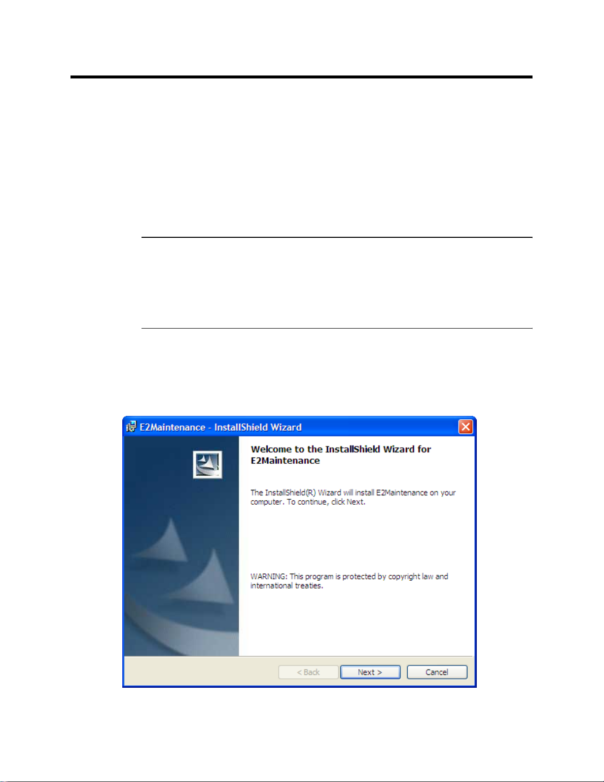
4. After a few seconds, a screen appears indicating that the
InstallShield Wizard is preparing to install the E2 Maintenance
Setup, then the E2 Maintenance InstallShield Wizard window
appears to guide you through installation.
Figure 1: Eagle 2 User Setup Installation Program
3 • Installing the Eagle 2 Maintenance Data Loader Program
Page 7

5. Follow the on-screen instructions in the InstallShield Wizard
Window to install the program.
6. If the InstallShield Wizard finds versions of Windows
your computer newer than those in the installation CD, it will ask
you if you want to keep these newer files. Click Yes.
7. When the InstallShield Wizard indicates that installation is
complete, click the Finish button.
8. Eject the installation CD from the CD-ROM drive and store it in a
safe place.
IrDA Downloading Cable
The Eagle 2 communicates with a computer via an on-board infrared
communication port that complies with IrDA protocol standards.
®
files on
NOTE: If your computer has a built-in infrared port, you do not need
an adapter cable to download data.
If your computer does not have an infrared port, you will need to
install an IrDA/USB adapter cable on your computer to use the Eagle 2
Maintenance Data Loader Program with your Eagle 2. The IrDA/USB
cable is available from RKI Instruments, Inc. See the Spare Parts List
at the end of this manual for the RKI part number. This cable can also
be found on many electronic supply websites.
®
Some versions of Windows
drivers loaded in Windows
already have several infrared device
®
and will automatically recognize a cable
during the installation process and guide you in installing the drivers.
Other versions of Windows
®
will require you to load device drivers
provided by the manufacturer of the cable during the installation
process. RKI makes no warranty for the operation or compatibility of
the drivers with any particular device.
IrDA Downloading Cable • 4
Page 8

Installing an IrDA Adapter Cable
After installing the Eagle 2 Maintenance Data Loader Program,
connect the IrDA/USB cable to your computer and follow the
manufacturer’s instructions for installing the cable on your computer.
Make sure the cable is compatible with your Windows® operating
system.
If you do not have instructions from the cable manufacturer for
installing your cable, see your Windows documentation. In general,
you must go to the Control Panel and use the Add Hardware Wizard to
install the cable drivers.
Windows
®
Wire less Link Operation Note
When using an IrDA adapter cable and the Eagle 2 Maintenance Data
Loader Program on a Windows
®
computer, it is necessary to make a
special setting in the Wireless Link Configuration window for proper
communication between the Eagle 2 and the Eagle 2 Maintenance Data
Loader Program. This must be done before attempting to use the
program. Follow these steps to make this setting:
®
1. Click Start on the Windows
Icon Tray.
2. If Control Panel is available to select in the Start menu, select it.
The Control Panel will appear.
If Contr ol Panel is not selectable in the Start menu but Settings is,
select Settings, then select Control Panel. The Control Panel will
appear.
3. Double click on Wireless Link. The Wireless Link Configuration
window will appear.
4. Click on the Image Transfer tab.
5. Deselect the selection box for “Use Wireless Link to transfer
images from a digital camera to your computer.”
5 • IrDA Downloading Cable
Page 9
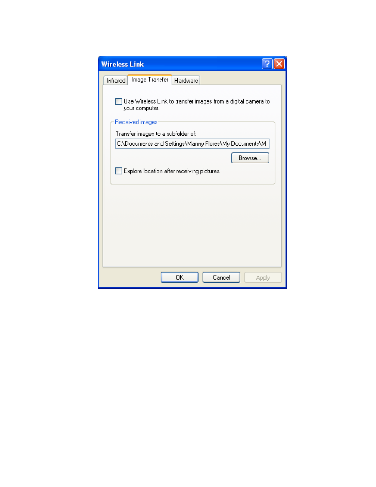
Figure 2: Image Transfer Tab
6. Click OK.
7. Close the Control Panel window.
IrDA Downloading Cable • 6
Page 10
Launching the Program
1. Click Start in the Windows® Icon Tray, then select Programs,
then select Eagle 2 Maintenance Data Loader. Your operating
system may also have a shortcut installed in the Start menu.
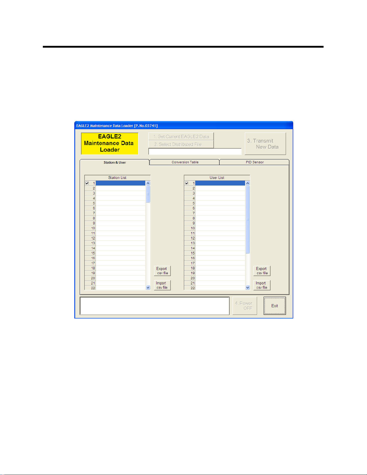
2. The Main Window will appear.
Figure 3: The Main Window
3. For convenience, make a shortcut of the Eagle 2 Maintenance Data
Loader Program and place it on the Windows
Windows
7 • Launching the Program
®
®
desktop. See your
documentation for information about making shortcuts.
Page 11
Connecting an Eagle 2 to
the Maintenance Data
Loader Program
Follow these steps to connect an Eagle 2 to the Maintenance Data
Loader Program:
1. Launch the Eagle 2 Maintenance Data Loader Program as
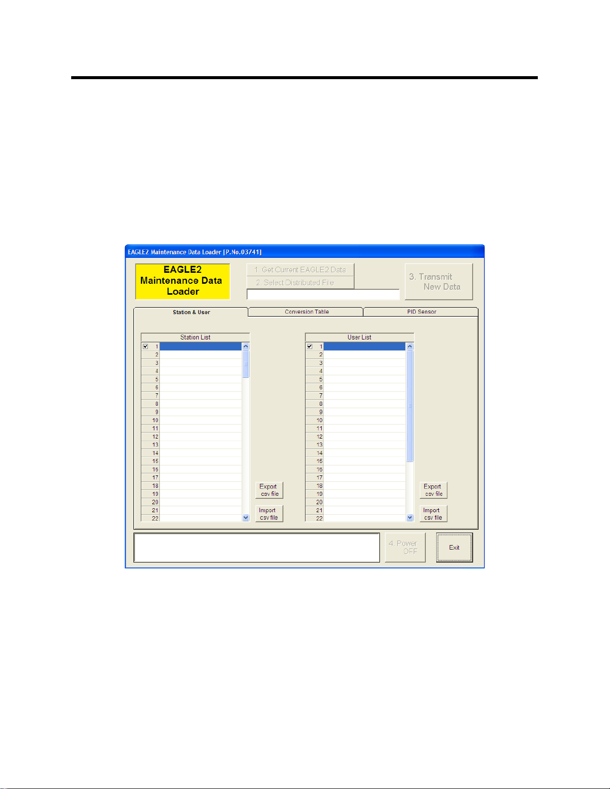
described in “Launching the Program” on page 7. The Main
Window displays.
Figure 4: The Main Window
2. Place the Eagle 2 within an inch or two of the infrared port on your
computer aligning the infrared port on the front of the Eagle 2 with
the infrared port on your computer.
If your computer does not have a built in infrared port, place the
Eagle 2 within an inch or two of the infrared port on the IrDA
adapter cable as shown in Figure 5 below, aligning the infrared
port on the front of the Eagle 2 with the infrared port on the cable.
Connecting an Eagle 2 to the Maintenance Data Loader Program • 8
Page 12
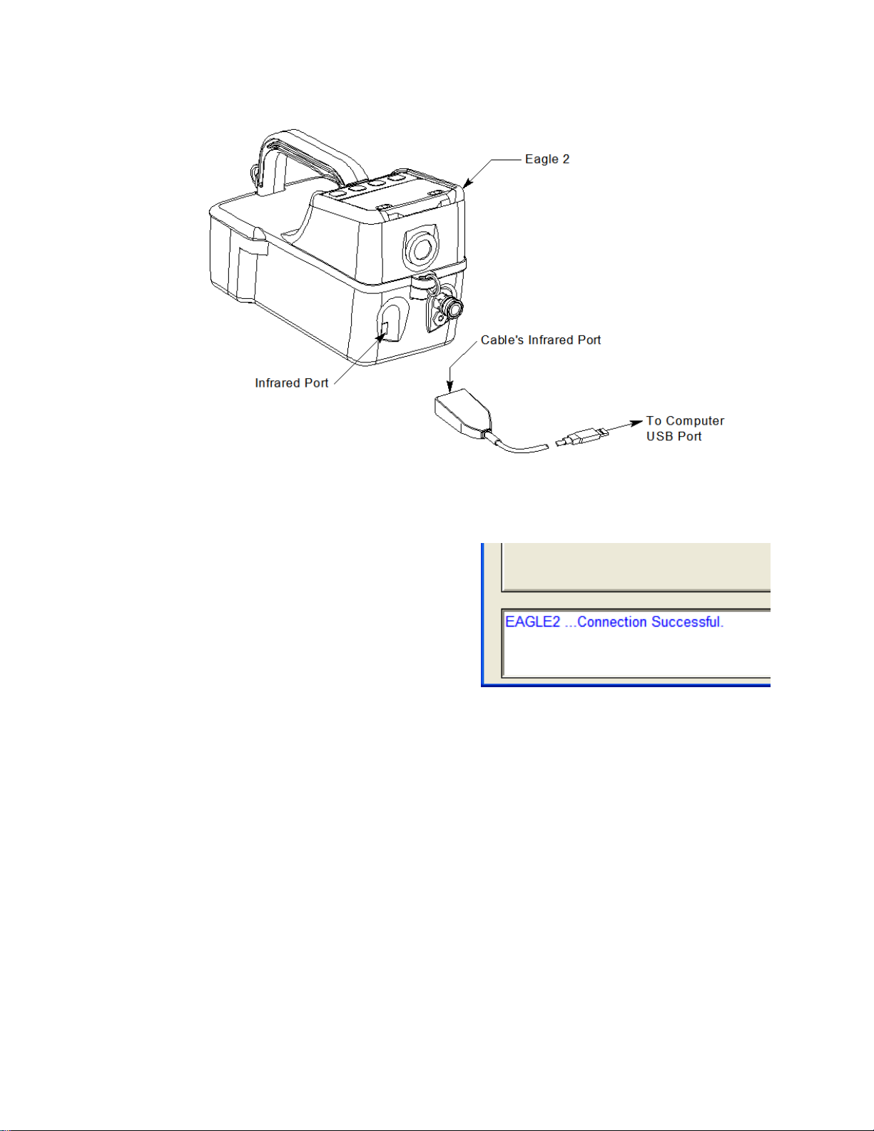
Figure 5: Aligning the Eagle 2 with the Cable Infrared Port
3. Press and hold the POWER
ENTER RESET button on
the Eagle 2 until you hear a
beep, then release it. The
Eagle 2 will begin it’s power
up sequence. If a successful
connection between the
Eagle 2 and the computer
occurs, the Get Current
EAGLE 2 Data control
button becomes active.
Figure 6: Connection Mes-
sage
You can now retrieve the connected instrument’s configuration
information using the Get Curr ent EAGLE 2 Data comma nd bu tto n.
You must retrieve the connected instrument’s configuration
information before you can perform operations such as saving the
instrument’s user and station IDs, catalytic combustible user defined
relative response gas list, or PID user defined relative response gas list
parameter configuration to a file and changing the instrument’s
parameter configuration.
9 • Connecting an Eagle 2 to the Maintenance Data Loader Program
Page 13

Control Buttons
There are 5 control buttons on the mai n sc reen: Get Current EAGLE
2 Data, Select Distributed File, Transmit New Data, Power OFF,
and Exit. These buttons are used for communication between the
Eagle 2 and the Eagle 2 Maintenance Data Lo ader Program.
Get Current EAGLE 2 Data
Use Get Current EAGLE 2 Data to load a connected instrument’s
user and station IDs, catalytic combustible user defined gases, and PID
user defined gas parameter configuration into the Maintenance Data
Loader Program so they can be updated if desired. Follow these steps
to retrieve a connected instrument’s parameter configuration and
update parameters that are available in the Eagle 2 Status area:
1. Launch the Eagle 2 Maintenance Data Loader Program as
described in “Launching the Program” on page 7.
2. Connect the Eagle 2 to the Maintenance Data Loader Program as
described in “Connecting an Eagle 2 to the Maintenance Data
Loader Program” on page 8.
Control Buttons • 10
Page 14
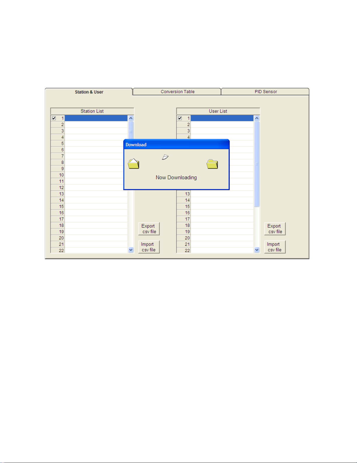
3. Click Get Current EAGLE 2 Data to retrieve the instrument’s
user and station ID, catalytic combustible user defined gases, and
PID user defined gas parameter configuration. The program
indicates that it is downloadi ng information from the instrument.
Figure 7: Instrument Information Downloading
4. The instrument’s user and station ID, catalytic combustible user
defined gases, and PID user defined gas parameter configuration
are now loaded in the Maintenance Data Loader Program and the
parameters are available for updating.
Select Distributed File
This control button only becomes active after data has been
downloaded to the Maintenance Data Loader Program. The function
controlled by this button is not needed for normal field use of the
program. This function and the text field below it are for use by field
service personnel with a factory program at their disposal to generate a
distributed file.
11 • Control Buttons
Page 15

Transmit New Data
After information has been updated in the pa rameter ta bs, thi s button is
used to upload that data to the Eagle 2.
NOTE: The Transmit New Data button transfers data from all tabs at
once. T o prevent the transmitting of empty parameter fields, it
is advisable that you download data from the instrument
before pressing the Transmit New Data button.
Power OFF
This button is used to turn off the Eagle 2 after all desired updates have
been made.
Exit
This button closes the Eagle 2 Maintenance Data Loader Program. Be
sure to turn off the Eagle 2 instrument before closing the Maintenance
Data Loader Program to prevent the Eagle 2 from remaining on and
draining battery voltage.
Control Buttons • 12
Page 16

Station & User Tab
The Station & User tab displays a list of Station IDs and User IDs. The
first time the Eagle 2 is connected to the Maintenance Data Loader
Program, this list will be blank. No Station IDs or User IDs are loaded
into the Eagle 2 at the factory. These are user-defined parameters that
may only be configured using the Maintenance Data Loader Program.
Up to 128 Station IDs and up to 32 User IDs may be defined.
13 • Station & User Tab
Figure 8: Station & User Tab
Page 17

CSV Files
Press to generate Station csv file
Press to generate User csv file
To edit the Station ID or User ID list, you will need to import a csv
(comma separated values) file into the program. A Station csv file and
a User csv file are provided with the program. In addition, you can
generate csv files for editing from the program. To access them, you
must press the “Export csv file” button for the Station and User IDs in
the Station and User tab.
Figure 9: Station csv File
Station & User Tab • 14
Page 18

The csv files can be opened, edited, and saved using a word processing
program such as Word, WordPad, or Notepad. The Station and User
csv files consist of the Station or User ID number and its associated
name. Below is an example of a Station csv file opened in WordPad.
Figure 10: Station csv File
Any existing Station or User IDs will be displayed. Undefined Station
or User IDs will appear as dashes. To edit a Station or User ID, delete
either the existing name or the dashes and replace them with the
desired name. The name may consist of any letter, number, or
character. If desired, you can save multiple Station and User ID files.
Loading User and Station IDs
To load new User and Station IDs, do the following:
1. Launch the Eagle 2 Maintenance Data Loader Program and
connect and instrument as described in “Connecting an Eagle 2 to
the Maintenance Data Loader Program” on page 8.
2. Download the instrument data to the program by pressing Get
Current EAGLE 2 Data.
3. Locate an existing Station or User csv file or generate a new one
for editing. To generate a new one, press “Export csv file” in the
Station and User tab for both the Station ID and User ID lists and
save the files in a convenient place.
15 • Station & User Tab
Page 19

4. Open the saved files in Word, WordPad, or Notepad, enter new
Station or User IDs, and save the files.
5. In the Station and User tab, press “Import csv file” for both the
Station ID and User ID and select the respective newly edited csv
file for each.
Press to import Station csv file
Press to import User csv file
Figure 11: Import csv File
6. Once the Station ID and User ID lists have been generated, select
the Station or User ID that will be loaded in the Eagle 2 as the
current one by clicking on it. A check mark will appear next to the
appropriate Station or User ID.
7. T o upload the new information from the Management Data Loader
Program to the Eagle 2, press Transmit New Data.
8. Turn off the Eagle 2 by pressing the Power OFF button
Station & User Tab • 16
Page 20

Conversion Table Tab
The Conversion Table tab is used to view the pre-defined relative
response gases for the catalyti c combustible channel and to edit or add
user-defined gases. The pre-defined gases can be found in the
Pre-Defined Table tab while the user-defined gases can be found under
the User-Defined Table tab.
Figure 12: Conversion Table
There are 8 columns in both the Pre-Defined Table tab and the UserDefined Table tab:
•No
This column represents the gas number. The gas numbers are 1-30.
•Name
This is what will appear in the Relative Response list of gases. The
name can be up to 3 characters long and the characters must be
upper case letters or numbers. No special characters may be used in
the Name column.
• Long Name
The Long Name column is used to better describe the target gas. It
17 • Conversion Table Tab
Page 21

may contain any character in upper- or lower-case.
•Factor
This value is the response factor for the listed gas relative to
methane. The factor for each pre-defined gas is factory defined.
The factor for any user-defined gases must be obtained through
testing as described in “Obtaining a Relative Response Factor” on
page 28. Even if not all of the user-defined catalytic combustible
channels are being defined, the Factor column must have a valid
number entered. A valid number for the Factor is a value between
0.01 and 25.00.
•1st
This column is for the low alarm point of each gas in ppm units.
• 2nd
This column is for the high alarm point of each gas in ppm units.
•Ratio
The ratio is the ppm value of the LEL for each gas. This value is
specific to each gas and can be easily determined. The maximum
value it may be set to is 150,000 ppm. If an invalid number is
entered, the box will turn red when the csv file is imported back
into the Maintenance Data Loader Program.
NOTE: If you define a gas whose LEL is above 50,000 ppm, the
%LEL reading in Measuring Mode will reflect the defined
ppm ratio, but the ppm reading in Measuring Mode will not
indicate above 50,000 ppm. For example, if you set the ratio
to be 150,000 ppm and set the catalytic combustible channel
to display the reading in ppm, the gas reading will not
indicate higher than 50,000 ppm, the equivalent of 33 %LEL
and 5% volume for this ratio, but will continue to indicate
%LEL readings up to 100 %LEL and %volume readings up to
15 %volume, the equivalent of 150,000 ppm, if the display
units are changed to %LEL or %volume. In addition, all
adjustable ppm parameters cannot be set higher than 50,000
ppm.
Conversion Table Tab • 18
Page 22

• Volt
This value determines the sensor voltage for the catalytic
combustible sensor. It can be set to 1.3 or 2.4. When set to 1.3, the
sensor is in methane elimination mode. When set to 2.4, the sensor
is reading at full response. Even if not all of the user-defined
catalytic combustible channels are being defined, the Volt column
must have a valid number entered. A valid number for the Volt
column is either 1.3 or 2.4.
While the pre-defined gases may not be edited, the 5 user-defined
gases may be edited by doing the following:
1. With the Maintenance Data Loader Program running, click on the
Conversion Data tab and then click on the User-Defined Table tab.
Figure 13: User-Defined Table
NOTE: Make sure you have downloaded the data from the EAGLE 2
to avoid erasing its data when updating the instrument using
the Transmit New Data button.
2. If no user-defined gases have been previously defined for the
connected instrument, the columns in User-Defined Table will be
19 • Conversion Table Tab
Page 23

blank. Any previously defined gases will appear.
3. Export the current data by pressing the “Export csv file” button.
Choose the file path you wish to save the file in.
4. Open the csv file using Notepad, Word, or WordPad. The example
below shows a csv file opened in WordPad. The list of gases are
associated with the numbers 1-5.
Figure 14: CSV File
If there were no previously defined gases, the csv file will appear
as the following:
Figure 15: Blank CSV File
5. The values in the csv file are all separated by commas. These
values are in the same order as the columns in the Maintenance
Conversion Table Tab • 20
Page 24

Data Loader Program. The first value is the gas number , the second
is the gas name, etc.
6. Edit the values you wish to change and save and close the file.
7. Return to the Maintenance Data Loader Program with the User-
Defined Table tab still up and press “Import csv file”.
8. Choose the file you just edited and press “Open”.
9. The values you entered in the csv file will appear in the User-
Defined Table.
10.If the program finds anything wrong with the values that were
entered, the box containing those values will turn red. Make sure
that you have entered valid characters for each field.
11.Once all of the data you wish to enter has been entered and is
correct, transmit the new data to the connected instrument by
pressing Transmit New Data.
21 • Conversion Table Tab
Page 25

PID Sensor Tab
The PID Sensor tab is used to view the pre-defined relative response
gases and to view or define the 1 user-defined relative response gas.
Every gas has a low and high range which are displayed in the Low
Range tab and High Range tab, respectively.
Figure 16: PID Sensor
There are 13 columns in both the High and Low Range tabs:
•No
This column represents the gas number. They are numbered 1-17.
•Name
This is what will appear in the Relative Response list of gases. The
name can be up to 3 characters long and the characters must be
upper case letters or numbers. No special characters may be used in
the Name column.
• Long Name
The Long Name column is used to better describe the target gas. It
may contain any character in upper- or lower-case.
PID Sensor Tab • 22
Page 26

• Full Scale
This is the full scale value for the target gas.
•Point
The point value indicates to what decimal place the gas readings are
shown. A value of 1/1 indicates a r eading to th e “ones” plac e whil e
a value of 1/100 indicates a reading to the “hundredths” place.
• Unit
The unit describes what units the gas reading is provided in. All
units are in ppm. While this parameter may be changed in the csv
file, units of ppm are the only acceptable units and changing this
parameter to %LEL or %vol will change the unit box to red.
• Digit
The digit is the increment of the gas readings.
•1st
This column is for the low alarm point of each gas in ppm units.
• 2nd
This column is for the high alarm point of each gas in ppm units.
• STEL
The STEL column displays the STEL values for each gas.
•TWA
The TWA column displays the TWA values for each gas.
• AutoCal
The AutoCal values are those that come up during the auto
calibration procedure. They are default values that may be changed
if the gas concentration in the calibration cylinder is different.
•Factor
This value is the Relative Response Factor for the PID channel. The
factor for each pre-defined gas is factory de fined. The factor for the
user defined gas must be obtained from Table 4 on page 29 or
through testing as described in “Obtaining a Relative Response
Factor” on page 28. A valid character for the Factor is a value
between 0.01 and 25.00.
23 • PID Sensor Tab
Page 27

There are limitations for the full scale and increment values that
depend on the factor for both the high range and the low range. Table 2
and Table 3 below list these limitations.
Table 1: High Range PID
Factor
Full Scale
(ppm)
Increment
0.25-0.49 500 0.2
0.50-0.74 1000 1
0.75-0.99 1500 1
1.00-1.24 2000 1
1.25-1.49 2500 1
1.50-1.99 3000 2
2.00-2.49 4000 2
2.50-4.99 5000 2
5.00-7.49 10000 10
7.50-9.99 15000 10
10.00-14.49 20000 10
15.00-24.49 30000 20
25.00 50000 20
Table 2: Low Range PID
Factor
Full Scale
(ppm)
Increment
0.20-0.29 10.00 0.01
0.30-0.39 15.00 0.01
0.40-0.49 20.00 0.01
0.50-0.59 25.00 0.01
0.60-0.79 30.00 0.02
0.80-0.99 40.00 0.02
PID Sensor Tab • 24
Page 28

Table 2: Low Range PID
Factor
Full Scale
(ppm)
Increment
1.00-1.99 50.00 0.02
2.00-2.99 100.0 0.1
3.00-3.99 150.0 0.1
4.00-5.99 200.0 0.1
6.00-7.99 300.0 0.2
8.00-9.99 400.0 0.2
10.00 500.0 0.2
While the pre-defined gases may not be edited, the 1 user-defined gas
may be edited by doing the following:
1. With Maintenance Data Loader Program running, click on the PID
Sensor tab and then click on the High Range tab.
25 • PID Sensor Tab
Figure 17: High Range Tab
Page 29

NOTE: Make sure you have downloaded the data from the EAGLE 2
to avoid erasing its data when updating the instrument using
the Transmit New Data button.
2. If no user-defined PID gas has been previously defined for the
connected instrument, the name and long name will both appear as
PID for the High Range and Low Range tabs. The full scale, digit,
and factor values will appear as shown in Table 4 below. The rest
of the fields will contain asterisks (*****).
Table 3: Default Values for User Defined PID Gas
Full Scale (ppm) Digit Factor
High Range
Low Range
3. Export the current data by pressing the “Export csv file” button.
2000 2 1.00
50.00 0.02 1.00
Choose the file path you wish to save the file in.
Figure 18: Save As
PID Sensor Tab • 26
Page 30

4. Open the csv file using Notepad, Word, or WordPad. The example
below shows a csv file opened in WordPad. The user defined PID
gas is number 17.
Figure 19: CSV File
5. The values in the csv file are all separated by commas. These
values are in the same order as the columns in the Maintenance
Data Loader Program. The first value is the gas number , the second
is the gas name, etc.
6. Edit the values you wish to change and save the file.
7. Return to the Maintenance Data Loader Program with the High
Range tab still up and press “Import csv file”.
8. Choose the file you just edited and press “Open”.
9. The values you entered in the csv file will appear in the High
Range tab.
10.If the program finds anything wrong with the values that were
entered, the box containing those values will turn red. Make sure
that you have entered valid characters for each field.
NOTE: The Name and Long Name for the Low Range and High
Range tabs must agree. If they do not, the program will keep
the Low Range Name and Long Name and change the High
11.Repeat step 1-step 10 for the Low Range tab.
12.Once all of the data you wish to enter has been entered and is
27 • PID Sensor Tab
Range to agree with it.
Page 31

correct, transmit the new data to the connected instrument by
pressing “Transmit New Data”.
Obtaining a Relative
Response Factor
If the gas that you want to monitor on the catalytic combustible or PID
channel is not included in the catalytic or PID relative reasponse lists,
you may define up to 5 gases for the catalytic combustible channel
using the Conversion Table tab and 1 gas for the PID channel using the
PID Sensor tab. Testing must be done using the desired target gas in
order to obtain the response factor value for the catalytic combustible
channel. To determine the relative response factor value for the PID
channel, first look in T able 4 for the desired gas. If the desired gas does
not appear in the table, you must obtain the response factor through the
testing procedure described below.
To determine the relative response factor value for the catalytic or PID
channels, do the following:
1. For determining the catalytic combustible channel relative
response factor, calibrate the catalytic combustible channel to
methane. For determining the PID channel relative response factor ,
calibrate the PID channel to isobutylene.
2. Obtain a gas sample of known concentration for the target gas you
wish to define. The sample needs to be at least 10% of the full
scale but RKI Instruments, Inc. recommends using 50% of the full
scale. If the concentration tested results in an overscale reading,
test a lower concentration.
3. Apply the gas sample to the EAGLE 2 and take note of the reading.
If the gas sample is of 50 %LEL concentration and the EAGLE 2
display shows a reading of 25 %LEL, then the factor for that gas is
2. Conversely, if the gas sample is of 50 %LEL concentration and
the EAGLE 2 display shows a reading of 100 %LEL, then the
factor for that gas is 0.5. This conversion factor value is what you
will enter in the Factor column of the gas you are defining.
Table 4 below has 4 columns:
• Gas/VOC-The most common name for the VOC (volatile organic
Obtaining a Relative Response Factor • 28
Page 32

compound)
• CAS No.-Sometimes it is easier to identify a VOC from the
internationally recognized CAS (Chemical Abstracts Service)
number
• Formula-Molecular formula for each VOC
• Response Factor (RF)-The relative response factor for each gas.
This is the value that is plugged into the Eagle 2 Maintenance Data
Loader Program.
Some abbreviations that appear in the table are:
• ZR-No response
• NV-Cannot be measured
Table 4: Response Factors Relative to Isobutylene
Gas/ VOC CAS No. Formula Relative
Response
Acetaldehyde 75-07-0 C2H4O 4.9
Acetic Acid 64-17-7 C2H4O2 36
Acetic Anhydride 108-24-7 C4H6O3 4
Acetone 67-64-1 C3H6O 0.7
Acetonitrile 75-05-8 CH3CN ZR
Acetylene 74-86-2 C2H2 ZR
Acrolein 107-02-8 C3H4O 4
Acrylic Acid 79-10-7 C3H4O2 2.7
Acrylonitrile 107-13-1 C3H3N ZR
Allyl alcohol 107-18-6 C3H6O 2.1
Allyl chloride 107-05-1 C3H5Cl 4.5
Ammonia 7664-41-7 NH3 8.5
Amyl acetate, n- 628-63-7 C7H14O2 1 . 8
Amyl alcohol 71-41-0 C5H12O 3.2
Aniline 62-53-3 C6H7N 0.5
Anisole 100-66-3 C7H8O 0.5
Arsine 7784-42-1 AsH3 2.5
Asphalt, petroleum fu m es 8052-42-4 1
Benzaldehyde 100-52-7 C7H6O 0.9
Benzene 71-43-2 C6H6 0.5
Benzenethiol 108-98-5 C6H5SH 0.7
Benzonitrile 100-47-0 C7H5N 0.7
Benzyl alcohol 100-51-6 C7H8O 1.3
Benzyl chloride 100-44-7 C7H7Cl 0.6
Benzyl formate 104-57-4 C8H8O2 0.8
29 • Obtaining a Relative Response Factor
Page 33

Gas/ VOC CAS No. Formula Relative
Response
Biphenyl 92-52-4 C12H10 0.4
Bis(2,3-epoxypropyl) ether 7/5/38 C6H10O3 3
Boron trifluoride 7637 07 2 BF3 ZR
Bromine 7726-95-6 Br2 20
Bromine pentafluoride 7789-30-2 BrF5 ZR
Bromobenzene 108-86-1 C6H5Br 0.7
Bromochloromethane 74-97-5 CH2ClBr ZR
Bromoethane 74-96-4 C2H5Br 5
Bromoethyl methyl ether, 2- 6482-24-2 C3H7OBr 2.5
Bromoform 75-25-2 CHBr3 2.8
Bromopropane, 1- 106-94-5 C3 H 7Br 1. 3
Bromotrifluoromethane 75-63-8 CF3Br ZR
Butadiene 106-99-0 C4H6 0.8
Butadiene diepoxid e, 1, 3- 146 4- 53-5 C4H6O2 4
Butane, n- 1 06-97-8 C4H10 46
Butanol, 1- 71-36-3 C4H10O 4
Buten-3-ol, 1- 598-32-3 C4H8O 1.2
Butene, 1- 1 06-98-9 C4H8 1.3
Butoxyethanol, 2- 111-76-2 C6H14O2 1.1
Butyl acetate, n- 123-86-4 C6H12O2 2.4
Butyl acrylate, n- 141-32-2 C7H12O2 1.5
Butyl lactate 138-22-7 C7H14O3 2.5
Butyl mercaptan 109-79-5 C4H10S 0.5
Butylamine, 2- 513-49-5 C4H11N 0.9
Butylamine, n- 109-73-9 C4H11N 1
Camphene 565-00-4 C10H16 0.5
Carbon diox i de 124-38-9 CO2 ZR
Carbon disulfide 75-15-0 CS2 1.4
Carbon monoxide 630-08-0 CO ZR
Carbon tetrabromide 558-13-4 CBr4 3
Carbon tetrachloride 56-23-5 CCl4 ZR
Carbonyl su l phide 463-58-1 COS ZR
Carvone, R- 6485-40-1 C10H14O 1
Chlorine 7782-50-5 Cl2 ZR
Chlorine dioxide 10049-04-4 ClO2 1
Chlorine trifluoride 7790-91-2 ClF3 ZR
Chloro-1,1,1,2-
tetrafluoroethane
Chloro-1,1,1-trifluo ro ethane, 2- 75-88-7 C2H2ClF3 ZR
Chloro-1,1,2,2tetrafluoroethane
Chloro-1,1,2-trifluoro et hane, 1- 421-04-5 C2H2ClF3 ZR
Chloro-1,1-difluoroethane, 1- 75-68-3 C2H3ClF2 ZR
Chloro-1,1-difluoroethane, 1- 75-68-3 C2H3ClF2 ZR
Chloro-1,1-difluoroethane, 2- 338-65-8 C2H3ClF2 ZR
Chloro-1,2,2-trifluoroethane 431-07-2 C2H2ClF3 ZR
2837-89-0 C2HClF4 ZR
354-25-6 C2HClF4 ZR
Obtaining a Relative Response Factor • 30
Page 34

Gas/ VOC CAS No. Formula Relative
Response
Chloro-1,3-butadie ne, 2- 126-99-8 C4H5Cl 3.2
Chloro-1-fluoroethane, 1- 1615-75 -4 C2H4ClF ZR
Chloro-2-fluoroethane, 1- 762-50-5 C2H4ClF ZR
Chloroacetaldehyde 107-20-0 C2H3OCl ZR
Chlorobenzene 108-90-7 C6H5Cl 0.5
Chlorodifluoromethane 75-45-6 CHClF2 ZR
Chloroethane 75-00-3 C2H5Cl ZR
Chloroethanol 2- 107-07-3 C2H5ClO 10
Chloroethyl methyl ether, 2- 627-42-9 C3H7ClO 2.6
Chlorofluoromethane 593-70-4 CH2ClF ZR
Chloroform 67-66-3 CHCl3 ZR
Chloromethane 74-87-3 CH3Cl ZR
Chloropentafluoroethane 76-15-3 C2ClF5 ZR
Chlorotoluene, o- 95-49-8 C7H7Cl 0.5
Chlorotoluene, p- 108-41-8 C7H7Cl 0.5
Chlorotrifluoroethylene 79-38-9 C2ClF3 1
Chlorotrifluoromethane 75-72-9 CClF3 ZR
Citral 5392-40-5 C10H16O 1
Citronellol 26489-01-0 C10H20O 1
Cresol, m- 108-39-4 C7H8O 1.1
Cresol, o- 95-48-7 C7H8O 1.1
Cresol, p- 106-44-5 C7H8O 1.1
Crotonaldehyde 4170-30-3 C4H6O 1
Cumene 98-82-8 C9H12 0.6
Cyanamide 420-04-2 CH2N2 ZR
Cyanogen bromide 506-68-3 CN Br ZR
Cyanogen chloride 506-77-4 CNCl ZR
Cyclohexane 110-82-7 C6H12 1.3
Cyclohexanol 108-93-0 C6H12O 2.9
Cyclohexanone 108-94-1 C6H10O 1.1
Cyclohexene 110-83-8 C6H10 0.8
Cyclohexylamine 108-91-8 C6H13N 1
Cyclopentane 287-92-3 C5H10 4
Decane, n- 124-18-5 C10H22 1
Diacetone alcoho l 123-42-2 C6H12O2 0.8
Dibenzoyl peroxide 94-36-0 C14H10O4 0.8
Diborane 19287-45-7 B2H6 ZR
Dibromochloromethane 124-48-1 CHBr2Cl 10
Dibromodifluoromethane 75-61-6 CF2Br2 ZR
Dibromoethane 1,2- 106-93-4 C2H4Br2 2
Dibromotetrafluoroethane ,
1,2Dibutyl hydrogen phosphate 107-66-4 HC8H18
Dichloro-1,1,1-trifluoroethane,
2,2-
124-73-2 C2F4Br2 ZR
4
PO4
306-83-2 C2HCl2F3 ZR
31 • Obtaining a Relative Response Factor
Page 35

Gas/ VOC CAS No. Formula Relative
Response
Dichloro-1,1-diflu oroethane,
1,2Dichloro-1,2,2-trifluoroethane,
1,2Dichloro-1,2-diflu oroethane,
1,2Dichloro-1-fluoroet ha ne, 1, 1- 1717-00-6 C2H3Cl2F ZR
Dichloro-1-fluoroet ha ne, 1, 1- 1717-00-6 C2H3Cl2F ZR
Dichloro-1-fluoroet ha ne, 1, 2- 430-57-9 C2H3Cl2F ZR
Dichloro-1-propene, 2, 3- 78 -8 8- 6 C3H4Cl2 1.4
Dichloro-2,2,-difluoroethane,
1,1Dichloroacetylene 7572-29-4 C2Cl2 5
Dichlorobenzene o- 95-50-1 C6H4Cl2 0.5
Dichlorodifluoromethane 75-71-8 CCl2F2 ZR
Dichloroethane 1,2- 107-06-2 C2H4Cl2 ZR
Dichloroethane, 1,1- 75-34-3 C2H4Cl2 ZR
Dichloroethene, 1,1- 75-35-4 C2H2Cl2 1
Dichloroethene, cis -1,2- 156-59-2 C2H2Cl2 0. 8
Dichloroethene, tra ns- 1, 2- 540-59-0 C2H2 Cl2 0.7
Dichloroethylene 1,2- 540-59-0 C2H2Cl2 0.8
Dichlorofluoromethane 75-43-4 CHFCl2 ZR
Dichloromethane 75-09-2 CH2Cl2 39
Dichloropropane, 1,2- 78-87-5 C3H6Cl2 ZR
Dichlorotetrafluoroet hane, 1,1- 374-07-2 C2Cl2F4 ZR
Dichlorotetrafluoroet hane, 1,2- 76-14-2 C2Cl2F4 ZR
Dicyclopentadiene 77-73-6 C10H12 0.9
Diesel Fuel 68334-30-5 0.8
Diethyl ether 60-29-7 C4H10O 0.9
Diethyl maleate 141-05-9 C8H12O4 2
Diethyl pht halate 84-66-2 C12H14O4 1
Diethyl sulphate 64-67-5 C4H10SO4 3
Diethyl sul phide 352-93-2 C4H10S 0.6
Diethylamine 109-89-7 C4H11N 1
Diethylaminoethanol, 2- 100-37-8 C6H15ON 2.7
Diethylaminopropylamine, 3- 104-78-9 C7H18N2 1
Difluoroethane, 1,1- 75-37-6 C2H4F2 ZR
Difluoroethane, 1,2- 624-72-6 C2H4F2 ZR
Difluoromethane 75-10-5 CH2F2 ZR
Dihydrogen selenid e 7783 07 5 H 2Se 1
Dihydroxy benzene, 1,2 120-80- 9 C6H6O2 1
Dihydroxy benzene, 1,3 108-46- 3 C6H6O2 1
Diisobutylene 107-39-1 C8H16 0.6
Diisopropyl ether 108-20-3 C6H14O 0.7
Diisopropylamine 108-18-9 C6H15N 0.7
Diketene 674-82-8 C4H4O2 2.2
Dimethoxymethane 109-87-5 C3H8O2 1.4
1649-08-7
354-23-4 C2HCl2F3 ZR
631-06-1
79-35-6
C2H2Cl2F2
C2H2Cl2F2
C2H2Cl2F2
ZR
ZR
ZR
Obtaining a Relative Response Factor • 32
Page 36

Gas/ VOC CAS No. Formula Relative
Response
Dimethyl cyclohexane, 1,2- 583-57-3 C8H16 1.1
Dimethyl di sulphide 624-92-0 C2H6S2 0.2
Dimethyl ether 115-10-6 C2H6O 1.3
Dimethyl ph t halate 131-11-3 C10H10O4 1
Dimethyl sulphate 77-78-1 C2H6O4S ZR
Dimethyl sulphide 75-18-3 C2H6S 0.5
Dimethylacetamide N,N- 127-19-5 C4H9NO 1.3
Dimethylamine 124-40-3 C2H7N 1.4
Dimethylaminoethanol 108-01-0 C4H11NO 1.5
Dimethylaniline, NN- 121-69-7 C8H11N 0.6
Dimethylbutyl acetat e 108-84-9 C8H16O2 1.6
Dimethylethylamine, NN- 598-56-1 C4H11N 0.8
Dimethylformamide 68-12-2 C3H7NO 0.9
Dimethylheptan-4-one, 2,6- 108-83-8 C9H18O 0.8
Dimethylhydrazine, 1,1- 57-14-7 C2H8N 2 1
Dinitrobenzene, m- 99-65-0 C6H4N2O4 3
Dinitrobenzene, o- 528-29-0 C6H4N2O4 ZR
Dinitrobenzene, p- 100-25-4 C6H4N2O4 5
Dinonyl phthalate 84-76-4 C26H42O 4 1
Dioxane 1,2- C4H8O2 1.5
Dioxane 1,4- 123-91-1 C4H8O2 1.5
Dipentene 138-86-3 C10H16 0.9
Diphenyl ether 1 01-84-8 C12H10O 0.8
Disulphur decafluoride 5714-22-7 S2F10 ZR
Disulphur dichloride 10025-67-9 S2Cl2 3
Di-tert-butyl-p-cresol 2409-55-4 C11H16O 1
Divinylbenzene 1321-74-0 C10H10 0.4
Dodecanol 112-53-8 C12H26O 0.9
Enflurane 13838-16-9
Epichlorohydrin 106-89-8 C3H5ClO 8
Epoxypropyl isop ro pyl ether,
2,3Ethane 74-84-0 C2H6 ZR
Ethanol 64-17-5 C2H6O 8.7
Ethanolamine 141-43-5 C2H7NO 3
Ethoxy-2-propanol, 1- 1569-02-4 C5H10O2 2
Ethoxyethanol, 2- 110-80-5 C4H10O2 29.8
Ethoxyethyl acetate, 2- 111-15-9 C6H12O3 3
Ethyl (S)-(-)-lactate 97-64-3 C5H10O3 3
Ethyl acet ate 141-78-6 C4H8O2 3.6
Ethyl acrylate 140-88-5 C5H8O2 2
Ethyl amine 75-04-7 C2H7N 1
Ethyl benzene 100-41-4 C8H10 0.5
Ethyl butyrate 105-54-4 C6H12O2 1
Ethyl chloroformate 541-41-3 C3H5O2Cl 80
Ethyl cyanoacrylate 7085-85-0 C6H7O2N 1.5
Ethyl decanoate 110-38-3 C12H24O2 1.8
Ethyl form ate 109-94-4 C3H6O2 30
4016-14-2 C6H12O2 1.1
C4H2F5ClO
ZR
33 • Obtaining a Relative Response Factor
Page 37

Gas/ VOC CAS No. Formula Relative
Response
Ethyl hexanoate 123-66-0 C8H16O2 2.6
Ethyl hexanol, 2- 105-76-7 C8H18O 1.5
Ethyl hexyl acrylate , 2- 103-11-7 C11H20O2 1
Ethyl mercaptan 75-08-1 C2H6S 0.7
Ethyl octanoate 106-32-1 C10H20O2 2.3
Ethylene 74-85-1 C2H4 8
Ethylene dinitrate 628-96-6 C2H4O6N2 ZR
Ethylene glycol 107-21-1 C2H6O2 20
Ethylene oxide 75-21-8 C2H4O 15
Ferrocene 102-54-5 C10H10Fe 0.8
Fluorine 7782-41-4 F2 ZR
Fluoroethane 353-33-6 C2H5F ZR
Fluoromethane 593-53-3 CH3F ZR
Formaldehyde 50-00-0 CH2O ZR
Formamide 75-12-7 CH3ON 2
Formic acid 64-18-6 CH2O2 ZR
Furfural 98-01-1 C5H4O2 1.4
Furfuryl alcohol 98-00-0 C5 H 6O2 2
Gasoline vapors 8006-61-9 1.1
Gasoline vapors 8006-61-9 0.8
Gasoline vapors 92 octane 8006-61-9 0.8
Germane 7782-65-2 GeH4 10
Glutaraldehyde 111-30-8 C5H8O2 0.9
Halothane 151-67-7
Helium He ZR
Heptan-2-one 110-43-0 C7H14O 0.7
Heptan-3-one 106-35-4 C7H14O 0.8
Heptane n- 142-82-5 C7H16 2. 1
Hexachloroethane 67-72-1 C2Cl6 ZR
Hexafluoroethane 76-16-4 C2F6 ZR
Hexamethyldisilazane,
1,1,1,3,3,3-.
Hexamethyldisiloxane. 107-46-0
Hexan-2-one 591-78-6 C6H12O 0.8
Hexane n- 1 10-54-3 C6H14 4.2
Hexene, 1- 592-41-6 C6H12 0.9
Hydrazine 302-01-2 H4N2 3
Hydrazoic acid 7782-79-8 HN3 ZR
Hydrogen 1333-74-0 H2 ZR
Hydrogen bromide 10035-10-6 HBr ZR
Hydrogen chloride 7647-01-0 HCl ZR
Hydrogen cyanide 74-90-8 HCN ZR
Hydrogen fluoride 7664- 39-3 HF ZR
Hydrogen peroxide 772 2- 84-1 H2O2 4
Hydrogen sulfide 6/4/83 H2S 4
999-97-3
CF3CHBrCl
C6H19NSi2
C6H18OSi2
ZR
1
0.3
Obtaining a Relative Response Factor • 34
Page 38

Gas/ VOC CAS No. Formula Relative
Response
Hydroquinone 123-31-9 C6H6O2 0.8
Hydroxypropyl acryl at e 2- 999 -61 -1 C6H10O3 1.5
Iminodi(ethylamine) 2,2- 111-40-0 C4H13N3 0. 9
Iminodiethanol 2,2' - 111-42-2 C4H11NO2 1.6
Indene 95-13-6 C9H8 0.5
Iodine 7553-56-2 I2 0.2
Iodoform 75-47-8 CHI3 1.5
Iodomethane 74-88-4 CH3I 0.4
Isoamyl acetate 123-92-2 C7H14O2 1.6
Isobutane 75-28-5 C4H10 8
Isobutanol 78-83-1 C4H10O 3.5
Isobutyl acetate 110-19-0 C6H12O2 2.3
Isobutyl acrylate 106-63-8 C7H12O2 1.3
Isobutylene 115-11-7 C4H8 1
Isobutyraldehyde 78-84-2 C4H8O 1.2
Isocyanates, all NV
Isodecanol 25339-17-7 C10H22O 0.9
Isoflurane 26675-46-7
Isononanol 2452-97-9 C9H20O 1.5
Isooctane 565-75-3 C8H18 1.1
Isooctanol 26952-21-6 C8H18O 1.7
Isopentane 78-78-4 C5H12 6
Isophorone 78-59-1 C9H14O 0.8
Isoprene 78-79-5 C5H8 0.7
Isopropanol 67-63-0 C3H8O 4.4
Isopropyl acetate 108-21-4 C5H10O2 2.2
Isopropyl chloroformate 108-23-6 C4H7O2Cl 1.6
Jet Fuel JP-4 0.8
Jet Fuel JP-5 0.7
Jet Fuel JP-8 0.7
Kerosene 8008-20-6 0.8
Ketene 463-51-4 C2H2O 3
Liquefied petroleum gas 68476-85-7 ZR
Maleic anhydride 108-31-6 C4H2O3 2
Mercaptoacetic acid 68-11-1 C2H4O2S 1
Mercury 7439-97-6 Hg NV
Mercury alkyls NV
Mesitylene 108-67-8 C9H12 0.3
Methacrylic acid 79-41-4 C4H6O2 2.3
Methacrylonitrile 126-98-7 C4H5N 5
Methane 74-82-8 CH4 ZR
Methanol 67-56-1 CH4O 200
Methoxyethanol, 2- 109-86-4 C3H8O2 2.7
Methoxyethoxyethanol, 2- 111-77-3 C5H12O3 1.4
Methoxymethyl ethoxy-2-
propanol
Methoxypropan-2-ol 107-98-2 C4H10O2 3
34590-94-8 C7H16O3 1.3
C3H2ClF5O
ZR
35 • Obtaining a Relative Response Factor
Page 39

Gas/ VOC CAS No. Formula Relative
Response
Methoxypropyl acetate 108-65-6 C6H12O3 1.2
Methyl acetate 79-20-9 C3H6O2 5.2
Methyl acrylate 96 -3 3- 3 C4H6O2 3.4
Methyl bromide 74-83-9 CH3Br 1.9
Methyl cyanoacrylate 137-05-3 C5H5O2N 5
Methyl ethyl ketone 78-93-3 C4H8O 0.8
Methyl ethyl ketone p er oxi des 1338-23-4 C8H 18O2 0.8
Methyl formate 107-31-3 C2H4O2 ZR
Methyl isobutyl ketone 108-10-1 C6H12O 0.8
Methyl isocyanate 624-83-9 C2H3NO ZR
Methyl isothiocyan at e 556-61-6 C2H3NS 0.6
Methyl mercaptan 74-93-1 CH 4S 0.7
Methyl methacryl ate 80-62-6 C5H8O2 1.6
Methyl propyl ketone 107-87-9 C5H10O 0.8
Methyl salicylate 119-36-8 C8H8O3 1.2
Methyl sulphide 75-18-3 C2H6S 0.5
Methyl t-butyl ether 1634-04-4 C5H12O 0.8
Methyl-2-propen- 1-ol, 2- 51 -4 2- 8 C4H8O 1.1
Methyl-2-pyrrolidinone, N- 872-50-4 C5H9NO 0.9
Methyl-4,6-dinitrophenol, 2- 534-52-1 C7H6N2O5 3
Methyl-5-hepten- 2- one, 6- 110-93-0 C8H14O 0.8
Methylamine 74-89-5 CH5N 1.4
Methylbutan-1-ol , 3 - 123 -51 -3 C5H 12O 3.4
Methylcyclohexane 108-87-2 C7H14 1.1
Methylcyclohexanol, 4- 589-91-3 C7H14O 2.4
Methylcyclohexa n o ne 2- 583-60-8 C7H12 O 1
Methylheptan-3-one, 5- 541-85-5 C8H16O 0.8
Methylhexan-2-one, 5- 110-12-3 C7H14O 0.8
Methylhydrazine 60-34-4 CH6N2 1.3
Methyl-N-2,4, 6-
tetranitroaniline, NMethylpent-3-en- 2- one, 4- 141-79-7 C6H10O 0.7
Methylpentan-2-ol , 4- 108 -11-2 C6H14O 2.8
Methylpentane-2 ,4-diol, 2- 107-41-5 C6H14O2 4
Methylpropan-2-ol, 2- 75-65-0 C4H10O 3.5
Methylstyrene 25013-15-4 C9H10 0.5
Mineral oil 8042-47-5 0.8
Mineral spirits 64475-85-0 0.8
Naphthalene 91-20-3 C10H8 0.4
Nitric oxide 10102-43-9 NO 8
Nitroaniline 4- 100-01-6 C6H6N2O2 0.8
Nitrobenzene 98-95-3 C6H5NO2 1.7
Nitroethane 79-24-3 C2H5NO2 ZR
Nitrogen dioxide 10102-44-0 NO2 10
Nitrogen trichloride 10025-85-1 NCl3 1
Nitrogen trifluoride 7783-54-2 NF3 ZR
Nitromethane 75-52-5 CH3NO2 ZR
Nitropropane, 1- 108-03-2 C3H7NO2 ZR
479-45-8 C7H5N5O8 3
Obtaining a Relative Response Factor • 36
Page 40

Gas/ VOC CAS No. Formula Relative
Response
Nitropropane, 2- 79-46-9 C3H7NO2 ZR
Nitrous oxide 10024-97-2 N2O ZR
Nonane, n- 111-84-2 C9H20 1. 3
Norbornadiene, 2,5 - 121 -46-0 C7H8 0.6
Octachloronaphthalene 2234-13-1 C10Cl8 1
Octane, n- 111-65-9 C8H18 1.6
Octene, 1- 111-66-0 C8H16 0.7
Oxalic acid 144-62-7 C2H2O4 ZR
Oxalonitrile 460-19-5 C2N2 ZR
Oxydietha nol 2,2- 111-4 6-6 C4H10O3 4
Oxygen O2 ZR
Ozone 10028-15-6 O3 ZR
Paraffin wax, fume 8002-74-2 1
Paraffins, normal 6477 1- 72-8 1
Pentacarbonyl iron 13463-40-6 FeC5O5 1
Pentachloroethane 76-01-7 C2HCl5 ZR
Pentachlorofluoroethane 354-56-3 C2Cl5F ZR
Pentafluoroethane 354-33-6 C2HF5 ZR
Pentan-2-one 107-87-9 C5H10O 0.8
Pentan-3-one 96-22-0 C5H10O 0.8
Pentandione, 2,4- 123-54-6 C5H8O2 0.8
Pentane, n- 109-66-0 C5H12 7.9
Peracetic acid 79-21-0 C2H4O3 2
Perchloryl fluoride 7616-94-6 Cl03F ZR
Perfluoropropane 76-19-7 C3F8 ZR
Petroleum ether 0.9
Phenol 108-95-2 C6H6O 1.2
Phenyl propene, 2- 98-83-9 C9H10 0.4
Phenyl-2,3-epoxypropyl ether 122-60-1 C9H10O2 0.8
Phenylenediamine, p- 106-50-3 C6H8N2 0.6
Phosgene 75-44-5 COCl2 ZR
Phosphine 7803-51-2 PH3 2
Picoline, 3- 108-99-6 C6H7N 0.9
Pinene, alpha 80-56-8 C10H16 0.3
Pinene, beta 127-91-3 C10H16 0.3
Piperidine 110-89-4 C5H11N 0.9
Piperylene 504-60-9 C5H8 0.7
Prop-2-yn-1-ol 107-19-7 C3H4O 1.3
Propan-1-ol 71-23-8 C3H8O 4.8
Propane 74-98-6 C3H8 ZR
Propane-1,2-diol, total 57-55-6 C3H8O2 10
Propene 115-07-1 C3H6 1.4
Propionaldehyde 123-38-6 C3H6O 1.7
Propionic acid 79-09-4 C3H6O2 8
Propyl acetate, n- 109-60-4 C5H10O2 2.5
Propylene dinitrate 6423-43-4 C3H6N2O6 ZR
37 • Obtaining a Relative Response Factor
Page 41

Gas/ VOC CAS No. Formula Relative
Response
Propylene oxide 75-56-9 C3H6O 7
Propyleneimine 75-55-8 C3H7N 1.3
Pyridine 110-86-1 C5H5N 0.8
Pyridylamine 2- 504-29-0 C5H6N2 0.8
Silane 7803-62-5 SiH4 ZR
Sodium fluoroacetate 62-74- 8
Styrene 100-42-5 C8H8 0.4
Sulphur dioxide 9/5/46 S O 2 ZR
Sulphur hexafluorid e 2551- 62-4 SF6 ZR
Sulphur tetrafluoride 7783-60-0 SF4 ZR
Sulphuric acid 7664-93-9 H2SO4 ZR
Sulphuryl fluoride 2699-79-8 SO2F2 ZR
Terphenyls C18H14 0.6
Terpinolene 586-62-9 C10H16 0.5
Tert-butanol 75-65-0 C4H10O 2.6
Tetrabrom oethane, 1, 1,2,2- 79-27- 6 C2H2Br4 2
Tetracarbonylnickel 13463-39-3 NiC4O4 1
Tetrachloro-1,2-
difluoroethane, 1,1, 2, 2Tetrachloro-1-fluoroethane,
1,1,2,2Tetrachloro-2,2difluoroethane, 1,1, 1, 2Tetrachloro-2-fluoroethane,
1,1,1,2Tetrachloroethane, 1,1,1,2- 630-20-6 C2H2Cl4 ZR
Tetrachloroethane, 1,1,2,2- 79-34-5 C2H2Cl4 ZR
Tetrachloroethylene 127-18-4 C2Cl4 0.7
Tetrachloronapht halenes, all
isomers
Tetraethyl orthosilicate 78-10-4
Tetraethyllead 78-00-2 C8H20Pb ZR
Tetrafluoroethane, 1, 1, 1,2- 8 11-97-2 C2H2F4 ZR
Tetrafluoroethane, 1, 1, 2,2- 3 59-35-3 C2H2F4 ZR
Tetrafluoroethylene 116-14-3 C2F4 1
Tetrafluoromethane 75-73-0 CF4 ZR
Tetrahydrofuran 109-99-9 C4H8O 1.6
Tetramethyl orthos ilicate 681-84-5
Tetramethyl succ in oni tri le 3333-52-6 C8H12N2 1
Therminol 1
Thionyl chloride 9/7/19 SOCl2 ZR
Toluene 108-88-3 C7H8 0.5
Toluene-2,4-diisocyanate 584-84-9 C9H6N2O2 1.6
Toluenesulphony l chl or ide, p- 98-59- 9 C7H7SO2
Toluidine, o- 95-53-4 C7H9N 0.5
Tributyl phosphate 126-73-8
76-12-0 C2Cl4F2 ZR
354-14-3 C2HCl4F ZR
76-11-9 C2Cl4F2 ZR
354-11-0 C2HCl4F ZR
20020-02-4 C10H4Cl4 1
C2H2O2FNa
C8H20O4Si
C4H12O4Si
Cl
C12H27O4P
ZR
2
ZR
3
5
Obtaining a Relative Response Factor • 38
Page 42

Gas/ VOC CAS No. Formula Relative
Response
Tributylamine 102-82-9 C12H27N 1
Trichloro-1,1-difluoroethane,
1,2,2Trichloro-1,2-difluoroethane,
1,1,2Trichloro-2,2-difluoroethane,
1,1,1Trichloro-2-fluoroethane,
1,1,2Trichlorobenzene 1,2,4- 120-82-1 C6H3Cl3 0.6
Trichloroethane, 1,1, 1- 71-55-6 C2H3C l3 ZR
Trichloroethane, 1,1, 2- 79-00-5 C2H3C l3 ZR
Trichloroethylene 79-01-6 C2HCl3 0.7
Trichlorofluoromethane 75-69-4 CCl3F ZR
Trichloronitromethane 76-06-2 CCl3NO2 ZR
Trichlorophenoxyacetic acid,
2,4,5Trichloropropane 1,2,3- 9 6-18-4 C3H5Cl3 ZR
Trichlorotrifluoroetha ne, 1,1,1- 354-58-5 C2Cl3F3 ZR
Trichlorotrifluoroetha ne, 1,1,2- 76-13-1 C2Cl3F3 ZR
Triethylamine 121-44-8 C6H15N 0.9
Trifluoroethane, 1,1,1- 420 -46 -2 C2H3F3 ZR
Trifluoroethane, 1,1,2- 430 -66 -0 C2H3F3 ZR
Trifluoroethanol, 2,2, 2- 75-89-8 C2H3F3O ZR
Trifluoromethane 75-46-7 CHF3 ZR
Trimethylamine 53-50-3 C3H9N 0.5
Trimethylbenzen e m i xt ur es C9H 12 0.3
Trimethylbenzen e, 1, 3, 5- 108-67-8 C9H12 0.3
Trinitrotoluene 2,4,6- 118-96-7 C7H5N3 O6 ZR
Turpentine 8006-64-2 C10H16 0.6
TVOC 1
Undecane, n- 1120-21-4 C1 1H 2 4 0.9
Vinyl acetate 108-05-2 C4H6O2 1.1
Vinyl bromi de 593-60-2 C2H3Br 1
Vinyl chloride 75-01-4 C2H3Cl 2.1
Vinyl-2-pyrrolidinone, 1- 88 -1 2- 0 C6H9NO 0.9
Xylene mixed isomer s 1330-20-7 C8H10 0.4
Xylene, m- 108-38-3 C8H10 0.4
Xylene, o- 95-47-6 C8H10 0.6
Xylene, p- 106-42-3 C8H10 0.6
Xylidine, all 1300-73-8 C8H11N 0.7
354-21-2 C2HCl3F2 ZR
354-15-4 C2HCl3F2 ZR
354-12-1 C2HCl3F2 ZR
359-28-4 C2H2Cl3F ZR
93-76-5 C8H5O3Cl 3 1
39 • Obtaining a Relative Response Factor
Page 43

Spare Parts List
Table 5: Spare Parts List
Part Number Description
47-5027RK Cable, USB/IrDA adapter
71-0154RK EAGLE 2 Operator’s Manual
71-0191RK EAGLE 2 Maintenance Data Loader Program Operator’s
Manual (this document)
71-8003RK Eagle 2 Product CD, Includes the Eagle 2 Data Logger
Management Program, the Eagle 2 Maintenance Program,
and Operator’s Manuals for Each
Spare Parts List • 40
 Loading...