

Page 1

65-2513RK
Oxygen Transmitter
Operator’s Manual
Part Number: 71-0111RK
Revision: A
Released: 3/1/11
www.rkiinstruments.com
Page 2

WARNING
Read and understand this instruction manual before operating
detector . Improper use of the dete ctor could result in bodily harm
or death.
Periodic calibration and maintenance of the detector is essential
for proper operation and correct readings. Please calibrate and
maintain this detector regularly! Frequency of calibration
depends upon the type of use you have and the sensor types.
T ypical calibration frequencies for most applications a re between
3 and 6 months, but can be required more often or less often
based on your usage.
65-2513RK Oxygen Transmitter
Page 3

Product Warranty
RKI Instruments, Inc. warrants gas alarm equipment sold by us to be free from defects in
materials, workmanship, and performance for a period of one year fr o m date of shipment
from RKI Instruments, Inc. Any parts found defective withi n tha t period will be repaired
or replaced, at our option, free of charge. This warranty does not apply to those items
which by their nature are subject to deterioration or consumption in normal ser v ice, and
which must be cleaned, repaired, or replaced on a routine basis. Examples of such items
are:
W arranty is voided by abuse including mechanical damage, alteration, rough handling, or
repair procedures not in accordance with the operator’s manual. This warranty indicates
the full extent of our liability , a nd we are not r esponsible for removal or r eplacement costs,
local repair costs, transportation costs, or contingent expenses incurred without our prior
approval.
a) Absorbent cartridges d) Batteries
b) Pump diaphragms and valves e) Filter elements
c) Fuses
THIS WARRANTY IS EXPRESSLY IN LIEU OF ANY AND ALL OTHER
WARRANTIES AND REPRESENTATIONS, EXPRESSED OR IMPLIED,
AND ALL OTHER OBLIGATIONS OR LIABILITIES ON THE PART OF
RKI INSTRUMENTS, INC. INCLUDING BUT NOT LIMITED TO, THE
WARRANTY OF MERCHANTABILITY OR FITNESS FOR A
PARTICULAR PURPOSE. IN NO EVENT SHALL RK I INSTRUMENTS,
INC. BE LIABLE FOR INDIRECT, INCIDENTAL, OR CONSEQUENTIAL
LOSS OR DAMAGE OF ANY KIND CONNECTED WITH THE USE OF
ITS PRODUCTS OR FAILURE OF ITS PRODUCTS TO FUNCTION OR
OPERATE PROPERLY.
This warranty covers instruments and parts sold to users by authorized distributors,
dealers, and representatives as appointed by RKI Instruments, Inc.
We do not assume i ndemnification for a ny accident or damag e c au sed by the operatio n of
this gas monitor, and our warranty is limited to the replacement of parts or our complete
goods.
65-2 5 13R K Oxygen Transmitter
Page 4

Table of Contents
Overview . . . . . . . . . . . . . . . . . . . . . . . . . . . . . . . . . . . . . . . . . . . . . . . . . . . . . . . . . . . . . . . . . . . 1
Specifications. . . . . . . . . . . . . . . . . . . . . . . . . . . . . . . . . . . . . . . . . . . . . . . . . . . . . . . . . . . . . . . . 1
Description. . . . . . . . . . . . . . . . . . . . . . . . . . . . . . . . . . . . . . . . . . . . . . . . . . . . . . . . . . . . . . . . . . 2
Oxygen Detector . . . . . . . . . . . . . . . . . . . . . . . . . . . . . . . . . . . . . . . . . . . . . . . . . . . . . . . . . . . . . . . . . . . . . . 2
Amplifier . . . . . . . . . . . . . . . . . . . . . . . . . . . . . . . . . . . . . . . . . . . . . . . . . . . . . . . . . . . . . . . . . . . . . . . . . . . . 2
Junction Box. . . . . . . . . . . . . . . . . . . . . . . . . . . . . . . . . . . . . . . . . . . . . . . . . . . . . . . . . . . . . . . . . . . . . . . . . . 3
Installation . . . . . . . . . . . . . . . . . . . . . . . . . . . . . . . . . . . . . . . . . . . . . . . . . . . . . . . . . . . . . . . . . . 4
Mounting the Oxygen Transmitter. . . . . . . . . . . . . . . . . . . . . . . . . . . . . . . . . . . . . . . . . . . . . . . . . . . . . . . 4
Wiring the Oxygen Transmitter to a Controller . . . . . . . . . . . . . . . . . . . . . . . . . . . . . . . . . . . . . . . . . . . . 5
Start Up. . . . . . . . . . . . . . . . . . . . . . . . . . . . . . . . . . . . . . . . . . . . . . . . . . . . . . . . . . . . . . . . . . . . . 7
Introducing Incoming Power . . . . . . . . . . . . . . . . . . . . . . . . . . . . . . . . . . . . . . . . . . . . . . . . . . . . . . . . . . . 7
Setting the Fresh Air Signal. . . . . . . . . . . . . . . . . . . . . . . . . . . . . . . . . . . . . . . . . . . . . . . . . . . . . . . . . . . . . 7
Maintenance. . . . . . . . . . . . . . . . . . . . . . . . . . . . . . . . . . . . . . . . . . . . . . . . . . . . . . . . . . . . . . . . . 8
Preventive Maintenance . . . . . . . . . . . . . . . . . . . . . . . . . . . . . . . . . . . . . . . . . . . . . . . . . . . . . . . . . . . . . . . 8
Troubleshooting . . . . . . . . . . . . . . . . . . . . . . . . . . . . . . . . . . . . . . . . . . . . . . . . . . . . . . . . . . . . . . . . . . . . . . 9
Replacing Components of the Oxygen Transmitter . . . . . . . . . . . . . . . . . . . . . . . . . . . . . . . . . . . . . . . . 9
Calibration Frequency . . . . . . . . . . . . . . . . . . . . . . . . . . . . . . . . . . . . . . . . . . . . . . . . . . . . . . . 11
Calibration . . . . . . . . . . . . . . . . . . . . . . . . . . . . . . . . . . . . . . . . . . . . . . . . . . . . . . . . . . . . . . . . . 12
Preparing for Calibration. . . . . . . . . . . . . . . . . . . . . . . . . . . . . . . . . . . . . . . . . . . . . . . . . . . . . . . . . . . . . . 12
Setting the Fresh Air Reading. . . . . . . . . . . . . . . . . . . . . . . . . . . . . . . . . . . . . . . . . . . . . . . . . . . . . . . . . . 12
Setting the Zero Reading. . . . . . . . . . . . . . . . . . . . . . . . . . . . . . . . . . . . . . . . . . . . . . . . . . . . . . . . . . . . . . 12
Returning to Normal Operation. . . . . . . . . . . . . . . . . . . . . . . . . . . . . . . . . . . . . . . . . . . . . . . . . . . . . . . . 13
Parts List . . . . . . . . . . . . . . . . . . . . . . . . . . . . . . . . . . . . . . . . . . . . . . . . . . . . . . . . . . . . . . . . . . . 13
65-2513RK Oxygen Transmitter
Page 5

Overview
This instruction manual describes the oxygen transmitter. This manual also describes how
to install, start up, configure, maintain, and calibrate the transmitter when using it with a
gas monitoring controller. A parts list at the end of this manual lists replacement parts and
accessories for the oxygen transmitter. See the controller operator ’s manual for
information specific to the controller.
Specifications
Table 1 lists specifications for the oxygen transmitter.
Description Specification
Table 1:Specifications
Target Gas Oxygen (O
Area Classification Explosionproof for Class I, Groups B, C, and D
Input Voltage 24 VDC
(24 VDC is typical input. Transmitter will operate from
11 - 30 VDC)
Sampling Method Diffusion
Signal Output 4 - 20 mA
Detection R ange 0 to 25.0% volume
Accuracy ± 0.5% O
Response Time 90% in 30 seconds
Operating Temperature -20° C to 45° C
)
2
2
W ARNING: When using the 65-2513RK, you must follow the instructions and warnings
in this manual to assure proper and safe operation of the 65-2513RK and to
minimize the risk of personal injury. Be sure to maintain and period ically
calibrate the 65-2513RK as described in this manual.
65-2513RK Oxygen Transmitter • 1
Page 6
Description
This section describes the components of the oxygen transmitter. The transmitter consists
of the oxygen detector, amplifier, and junction box.
%
$
(factory-set)
Oxygen Detector
The detector’s sensing element along with signal conditioning components are
encapsulated within a conduit mounting black anodized aluminum housing. The sensing
element used is a capillary type that is not susceptible to output changes with cha nge s in
atmospheric pressure. Through a series of chemical and electronic reactions, the detector
produces a millivolt output that is proportional to the detection range. 3/4” NPT
mounting threads at the top of the detector allow you to m ount the detector to the
junction box or a 3/4” NPT conduit fitting. Two color-coded leads extend from the top of
the detector. Th e leads allow you to connect the detector to the amplifier.
)*
$
!#
$"
!"
"
-
POWER/SIG
SENSOR
"
-
&'(
.
&+
$
,
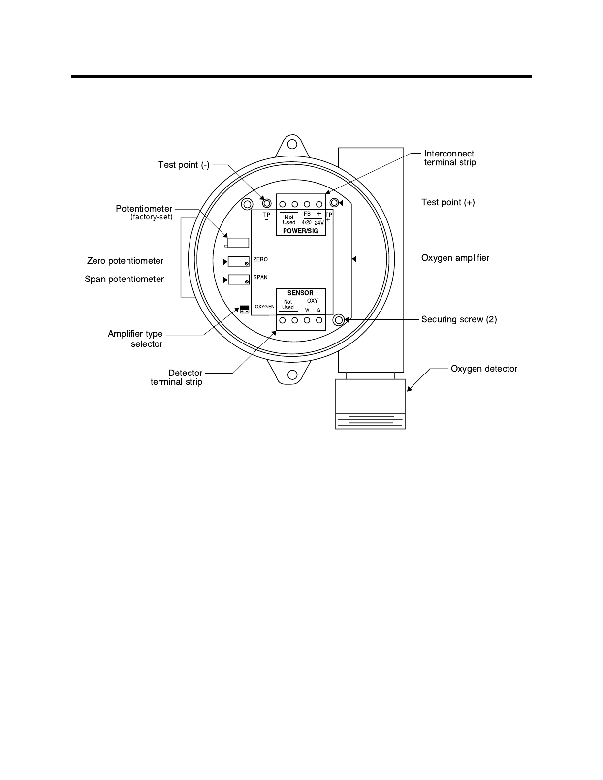
Figure 1: Oxygen Transmitter Component Location
Amplifier
The amplifier converts the millivolt output from the oxygen detector to a 4 - 20 mA signal
that is proportional to the detection range and transmits the signal to the controller via 2
wires. The amplifier includes the amplifier type selector, detector terminal strip,
interconnect terminal strip, span pot, zero pot, and test points (see Figure 1).
Amplifier Type Selector
The amplifier type selector is near the bottom left corner of the amplifier. It is below the
span pot and to the left of the detector terminal strip.
2 • 65-2513RK Oxygen Transmitt er
Page 7

The amplifier included with the oxygen transmitter is designed for use with RKI’s oxygen
and toxic gas transmitters. The amplifier type selector determines for which transmitter
the amplifier is intended. For oxygen transmitters, a jumper blo c k is installed over the
OXYGEN selector (see Figure 1).
Detector Terminal Strip
The detector terminal strip is the four-point terminal strip near the bottom of the
amplifier. Use the detector terminal strip to connect the oxygen detector to the amplifier.
NOTE: The oxygen detector is factory-wired to the amplifier. See the Installation section
of this manual for all wiring procedures related to the transmitter.
Interconnect Terminal Strip
The interconnect terminal strip is the four-point terminal strip near the to p of the
amplifier. Use the interconnect terminal strip to connect the amplifier to the controller.
Span Pot
The span pot is on the left side of the amplifier. Of the three pots, the span pot is closest to
the bottom of the amplifier. Use the span pot to adjust the transmitter’s response output
during the start-up and calibration procedures.
Zero Pot
The zero pot is directly above the span pot. Use the zero pot to adjust the transmitter’s
oxygen-free output during the calibration procedure.
CAUTION: The amplifier includes an additional potentiometer above the zero potentiometer.
It is factory-set. Do not adju st it.
Test Points
The test points (labeled TP- and TP+) are directly to the left and right of the interconnect
terminal strip. The test points produce a 100 - 500 mV output that is proportional to the
transmitter’s 4 - 20 mA output. Use the test points and a voltmeter to measure the
transmitter’s output during the start-up and calibration procedures.
Junction Box
Use the junction box to install the oxyg en transmitter at a mounting site that is remote
from the controller. The junction box also protects the amplifier and wiring connections
made to the amplifier. Use the two 3/4 in. conduit hubs to mount the detector to the
junction box (bottom hub) and connect wiring from the amplifier to the controller
(top hub).
NOTE: The oxygen detector and amplifier are factory-mounted to the junction box.
Use the junction box’s two mountin g holes to mount the oxygen transmitter to a vertical
surface at the monitoring site. Use the cover on the front of the junction box to access the
interior of the junct ion box.
65-2513RK Oxygen Transmitter • 3
Page 8

Installation
p.
This section describes procedures to mount the oxygen transmitter in the monitoring
environment and wire the transmitter to a controller.
Mounting the Oxygen Transmitter
1. Select a mounting site that is representative of the monitoring environment. Consider
the following when you select the mounting site.
• Select a site where the transmitter is not likely to be bumped or disturbed. Make
sure there is sufficient room to perform start-up, maintenance, and calibration
procedures.
• Select a site that is at normal breathing level.
CAUTION: Mount the ox ygen transmitter with the detector facing down (see Figure 2).
2. At the monitoring site, use #10 screws through the junction box’s two mounting holes
to secure the junction box to a vertical surface (see Figure 2).
0.25 in.
DIA.
2.75 in.
(7.0 cm)
5.2 in.
(13.2 cm)
Figure 2: Mounting the Oxygen Transmitter
Note: The junction box is
5.46 in.
(13.9 cm)
6.7 in. (max.)
(17.0 cm)
1.4 in. max
(3.6 cm)
4.0 in. (10.2 cm) dee
4 • 65-2513RK Oxygen Transmitt er
Page 9

Wiring the Oxygen Transmitter to a Controller
WARN ING: Alway s ve ri fy that the controller is off and power to the controller is off
before you make wiring connections.
1. Turn off the controller.
2. Turn off power to the controller.
3. Remove the junction box cover.
4. Verify that the detector leads are wired to the amplifier’s detector terminal strip. If
necessary, connect the leads to the detector terminal strip as shown in Figure 3.
5. Verify that the jumper block is installed over the OXYGEN selector of the amplifier
type selector as shown in Figure 3.
6. Install an appropriate cable bushing or conduit fitting on the top conduit hub of the
junction box.
7. Guide a two-conductor, shielded cable or two wires in conduit through the top
conduit hub of the junction box.
8. Connect the two wires to the interconnect terminal strip as follows (see Figure 3).
• Connect the positive wire to the terminal labeled 24V +.
• Connect the feedback wire to the terminal labeled FB 4/20.
CAUTION: If using shielded cable, leave the cable drain (shield) wire insulated and disconnected
at the transmitter. You will connect the opposite end of the cable’s drain wire at the
controller.
9. Secure the junction box cover to the junction box.
10. Route the cable or wires leading from the oxygen transmitter through one of the
conduit hubs at the controller. Install an appropriate cable bushing or conduit fitting
at the conduit hub.
CAUTION: Do not route power and transmitter wiring through the same conduit hub. The
power cable may disrupt the transmission of the transmitter signa l to the
controller.
65-2513RK Oxygen Transmitter • 5
Page 10

11. Connect the wires to the applicable transmitter terminal strip at the controller as
er
shown in Figure 3.
4 - 20 mA In
(FB or S)
+ 24 VDC
Cable Shield
Controller Transmitt
FB
+
4/20
W
OXY
24V
TP
+
G
Terminals,Typical
ZERO
SPAN
OXYGEN
TP
-
Not
Used
POWER/SIG
SENSOR
NOT
USED
Amplifier Type
Selector, Set to
OXYGEN
12. If using shielded cable, connect the cable’s drain wire to an available chassis ground at
Green
White
Oxygen Detector
Figure 3: Wiring the Oxygen Transmitter to a Controller
the controller. R KI controllers typically have a ground stud that is a convenient
grounding location.
6 • 65-2513RK Oxygen Transmitt er
Page 11

Start Up
This section describes procedures to start up the oxyg en tra nsmitter and place the
transmitter into normal operation with a controller.
Introducing Incoming Power
1. Complete the installation procedures described earlier in this manual.
2. Verify that the power wiring to the controller is correct and secure. Refer to the
controller operator’s manual.
3. Turn on or plug in the incoming power, then turn on the controller.
4. Verify that the controller is on and operating properly. Refer to the controller
operator’s ma nual.
CAUTION: Allow the detector to warm up for 5 minutes before you continue with the next
section, “Setting the Fresh Air Signal”.
Setting the Fresh Air Signal
NOTE: If you can verify that the detector is in a fresh air environment (environment
known to be of normal oxygen content and free of toxic and combustible gases),
it is not necessary to apply zero air when verifying or setting the fresh air
reading.
The procedure below describes applying zero emission air, usually called zero air , using a
calibration kit that includes a calibration cup, calibration gas, sample tubing, and a fixed
flow regulator with an on/off knob. RKI Instruments, Inc. recommends using a 0.5 LPM
(liters per minute) fixed flow regulator.
1. Unscrew and remove the junction box cover from the junction box.
2. Set a voltmeter to measure in the millivolt (mV) range.
3. Plug the voltmeter leads into the test points on the amplifier. Plug the positive lead
into the test point labeled TP+; plug the ne gative lead into the test point labeled TP-.
4. Screw the calibration cup onto the bottom of the detector.
5. Screw the regulator into the zero air calibration cylinder.
6. Use the sample tubing to connect the regulator to the calibration cup.
7. Turn the regulator’s on/off knob counterclockwise to open it. Gas will begin to flow.
8. Allow the gas to flow for 2 minutes.
9. Verify a voltmeter reading of 434 mV (±2 mV).
10. If necessary, use a flat-blade screwdriver to adjust the span pot until the voltmeter
reading is 434 mV (±2 mV).
11. Turn the regulator’s on/off knob clockwise to close it.
12. Unscrew the calibration cup from the detector.
13. Unscrew the regulator from the zero air calibration cylinder. For convenience, leave
the sample tubing connected to the regulator and the calibration cup.
14. Store the components of the calibration kit in a safe and convenient place.
15. Remove the voltmeter leads from the test points.
65-2513RK Oxygen Transmitter • 7
Page 12

16. Secure the junction box cover to the junction box.
Maintenance
This section describes maintenance procedures. It includes preventive maintenance,
troubleshooting, and component replacement procedures.
Preventive Maintenance
This section describes a preventive maintenance schedule to ensure the optimum
performance of the oxygen transmitter. It includes daily, monthly, and quarterly
procedures.
Daily
Verify a display reading of 20.9% oxygen at the controller. Investigate significant changes
in the reading.
Monthly
This procedure describes a test to verify that the oxygen transmitter responds properly to
oxygen deficiency.
NOTE: Performing a response test on the oxygen transmitter may cause alarms. Be sure
to put the controller into its calibration program or disable external alarms befor e
performing this test.
Preparing for the response test
1. Verify that the display reading for the channel you are testing is 20.9% oxygen.
If the display reading is not 20.9% oxygen, set the fresh air reading of the transmitter
as described in “Start Up” on page 7 of this man ual , then conti n ue this pr o c edure.
2. Set a voltmeter to measure in the millivolt (mV) range.
3. Remove the junction box cover, then plug the voltmeter leads into the test points on
the amplifier. Plug the positive lead into the test point labeled TP+; plug the negative
lead into the test point labeled TP-.
Performing the response test
1. Exhale into the bottom of the oxygen detector.
2. Stop exhaling into the bottom of the detector, then verify that the reading on the
voltmeter decreased from the normal reading (434 mV).
NOTE: If the reading does not decrease, calibrate the transmitter as described in
“Calibrati on” on page 12 of this manual.
3. Remove the voltmeter leads from the amplifier test points, then secure the junction
box cover to the junction box.
4. When the display reading rises above the decreasing alarm setpoint, return the
controller to normal operation.
Quarterly
Calibrate the detector as described in “Calibration” on page 12.
8 • 65-2513RK Oxygen Transmitt er
Page 13

Troubleshooting
The troubleshooting guide describes symptoms, probable causes, and recommended
action for problems you may encounter with the oxygen transmitter.
NOTE: This troubleshooting guide describes transmitter problems only. See the
controller operator’s manual for problems you may encounter with the
controller.
Table 2:Troubleshooting the Oxygen Transmitter
Condition Symptom(s) Probable Causes Recommended Action
Fail Condition • Controller indicates a
Slow or No
Response/
Difficult or
Unable to
Calibrate
fail condition.
• Transmitter responds
slowly or does not
respond to response
test.
• Unable to accurately
set the fresh air or
zero reading during
calibration.
• Transmitter requires
frequent calibration.
Note: Under “normal”
circumstances, the
transmitter requires
calibration once every
three mont hs.
Some applications may
require a more freque nt
calibration schedule.
Replacing Components of the Oxygen Transmitter
• The transmitter wiring
is disconnected or
misconnected.
• The transmitter is
malfunctioning.
• The calibration cylinder
is low, out-dated, or
defective.
• The transmitter is
malfunctioning.
1. Verify that the transmitter wiring is
correct and secure.
2. Calibrate the transm itt er.
3. If the fail condition continues, replace
the oxygen sensor.
4. If the fail condition continues, contact
RKI for further instruction.
1. Verify that the calibration cylinder
contains an adequate supply of a
fresh test sample.
2. If the calibration/response difficulties
continue, replace the oxygen sensor.
3. If the calibration/response difficulties
continue, contact RKI for further
instruction.
This section includes procedures to replace the oxygen detector and amplifier.
Replacing the Oxygen Detect or
1. Turn off the controller.
2. Turn off power to the controller.
3. Remove the junction box cover.
4. Disconnect the detector leads from the detector terminal strip. Note the position of the
color-coded leads as you remove them.
5. Unscrew the detector from the junction box.
6. Guide the detector leads of the replacement detector through the bottom conduit hub
of the junction box, then screw the mounting threads of the detector into the conduit
hub and tighten firmly.
65-2513RK Oxygen Transmitter • 9
Page 14

7. Connect the detector leads to the amplif ier’s detector terminal strip as shown in
Table 3 below and Figure 3 on page 6 of this manual.
Table 3:Reconnecting the Oxygen Detector
to the Amplifier
Detector Lead Detector Terminal Strip
White OXY W
Green OXY G
8. Turn on power to the controller
9. Turn on the controller.
10. Calibrate the replacement detector as described in “Calibration” on page 12 of this
manual.
Replacing the Amplifier
1. Turn off the controller
2. Turn off power to the controller.
3. Remove the junction box cover.
4. Disconnect the detector leads from the detector terminal strip.
5. Disconnect the wiring that connects the oxygen transmitter to the controller from the
amplifier’s interconnect terminal strip.
6. Unscrew and remove the two screws that secure the amplifier to the junction box.
The screws are at the top left and bottom right of the amplifier.
7. Remove the amplifier.
8. Place the new amplifier in the same position as the amplifier you removed in the
previous step.
9. Use the two screws you removed in step 6 to secure the amplifier to the junction box.
10. Reconnect the wiring that connects the controller and oxygen transmitter to the
amplifier’s interconnect terminal strip as shown in Table 4 below and Figure 3 on
page 6 of this manual.
Table 4:Reconnecting the Oxygen Amplifier
to the Controller
Amplifier Interconnect
T erminal Strip
4/20 4 - 20 (FB)
24V + (24 VDC)
Transmitter T ermin al Strip
Controller
10 • 65-2513RK Oxygen Transmit ter
Page 15

11. Reconnect the detector leads to the amplifier’s detector terminal strip as shown in
Table 5 below and Figure 3 on page 6 of this manual.
Table 5:Reconnecting the Oxygen Detector
Detector Lead Detector Terminal Strip
White OXY W
Green OXY G
12. Turn on pow er to the controller
13. Turn on the controller.
14. Calibrate the oxygen transmitter as described in “Calibration” on page 12 of this
manual.
Calibration Frequency
Although there is no particular calibration frequency that is correct for all applications, a
calibration frequency of every 3 months is adequate for most oxygen transmitter
applications. Unless experience in a particular application dictates otherwise, RKI
Instruments, Inc. recommends a calibration frequency of every 3 months for the oxygen
transmitter.
to the Amplifier
If an application is not very demanding, for example detection in a clean, temperature
controlled environment, and calibration adjustments a re minima l at calibration, then a
calibration frequency of every 6 months is adequate.
If the application is very demanding, for example if the environment is not well
controlled, then more frequent calibration than every 3 months may be necessary.
65-2513RK Oxygen Transmitter • 11
Page 16

Calibration
This section describes how to calibrate the oxygen transmitter. It includes procedures to
prepare for calibration, set the fr esh air r eading, set the zero r eading, and return to normal
operation. It describes the test using a calibration kit that includes a calibration cup,
calibration gas, sample tubing, and a fixed flow regulator with an on/off knob. RKI
Instruments, Inc. recommends using a 0.5 LPM (liters per minute) fixed flow regulator.
Prepari ng for Ca libration
NOTE: Calibrating the oxygen transmitter may cause alarms. Be sure to put the
controller into its calibration program or disable external alarms before
calibrating.
1. Unscrew and remove the junction box cover.
2. Set a voltmeter to measure in the millivolt (mV) range.
3. Plug the positive lead into the test point labeled TP+; plug the negative lead into the
test point labeled TP-.
4. Screw the calibration cup onto the detector housing.
Setting the Fresh Air Reading
NOTE: If you can verify that the oxygen transmitter is in a fres h air envir onment, you do
not need to apply zero air to the detector before adjusting the zero reading.
1. Screw the regulator into the zero air calibration cylinder.
2. Use the sample tubing to connect the regulator to the calibration cup.
3. Turn the regulator knob counterclockwise to open the regulator.
4. Allow the gas to flow for 2 minutes.
5. Verify a voltmeter reading of 434 mV (±2 mV).
6. If necessary, use a flat-bla de screwdriver to adjust the span pot on the amplifier unt il
the voltmeter reading is 434 mV (±2 mV).
7. Turn the regulator knob clockwise to close the regulator.
8. Unscrew the regulator from the zero air calibration cylinder.
9. Leave the sample tubing connected to the regulator and the calibration cup.
NOTE: Depending on the size of your zero air cylinder, it is possible that you will have a
different regulator for the zero air cylinder and the 100% nitrogen cylinder. If
necessary to fit the nitrogen cylinder, change the regulator.
Setting the Zero Reading
1. Screw the regulator into the 100% nitrogen calibration cylinder.
2. Turn the regulator knob counterclockwise to open the regulator.
3. Allow the gas to flow for two minutes and verify a reading of 100 mV (±2 mV).
4. If necessary, use the zero pot on the amplifier to adjust the reading to 100 mV (±2 mV).
12 • 65-2513RK Oxygen Transmit ter
Page 17

5. Turn the regulator knob clockwise to close the regulator.
6. Unscrew the regulator from the calibration cylind er.
7. Unscrew the calibration cup from the oxygen detector.
NOTE: For convenience, leave the components of the calibration kit connected by the
sample tubing.
Returning to Normal Operation
1. Remove the voltmeter leads from the am plif ier test points.
2. Secure the junction box cover to the junction box.
3. When the display reading rises above the decreasing alarm setpoint, return the
controller to normal operation.
NOTE: If you do not allow the oxygen reading to increase above the decreasing alarm
point, then unwanted alarms may occur.
4. Verify that the display reading increases and stabilizes at 20.9% volume.
5. Store the components of the calibration kit in a safe and convenient place.
Parts List
Table 6 lists replacement parts and accessories f or the oxygen transmitter.
T a ble 6:Par ts List
Part Number Description
06-1248RK Sample tubing (3/16 in. x 5/16 in.; specify length when ordering)
18-0405RK-01 Junction box (does not include lid)
18-0406RK Junction box lid
57-1062RK Amplifier for oxygen detector
65-2511RK Oxygen detector, capillary type, conduit-mounting
65-2513RK Oxygen transmitter (includes detector and amplifier)
71-0111RK 65-2513RK Oxygen Transmitter Operator’s Manual (this document)
81-F301RK-LV Calibration kit, 34 liter
81-0076RK-01 Zero air calibration cylinder (34 liter)
81-0078RK Calibration cylinder (100% nitrogen, 17-liter)
81-0078RK-01 Calibration cylinder (100% nitrogen, 34-liter)
81-1050RK Regulator with gauge and knob, 0.5 LPM, for 17 liter and 34 liter steel
calibration cylinders
81-1117RK Calibration cup
65-2513RK Oxygen Transmitter • 13
 Loading...