

Page 1

65-2496RK/65-2499RK
Carbon Monoxide Detector
Operator’s Manual
Part Number: 71-0156RK
Revision: 0
Released: 2/16/11
www.rkiinstruments.com
Page 2

WARNING
Read and understand this instruction manual before operating
detector . Improper use of the dete ctor could result in bodily harm
or death.
Periodic calibration and maintenance of the detector is essential
for proper operation and correct readings. Please calibrate and
maintain this detector regularly! Frequency of calibration
depends upon the type of use you have and the sensor types.
T ypical calibration frequencies for most applications a re between
3 and 6 months, but can be required more often or less often
based on your usage.
65-2496RK/65-2499RK CO Detector
Page 3

Product Warranty
RKI Instruments, Inc. warrants gas alarm equipment sold by us to be free from defects in
materials, workmanship, and performance for a period of one year fr o m date of shipment
from RKI Instruments, Inc. Any parts found defective withi n tha t period will be repaired
or replaced, at our option, free of charge. This warranty does not apply to those items
which by their nature are subject to deterioration or consumption in normal ser v ice, and
which must be cleaned, repaired, or replaced on a routine basis. Examples of such items
are:
W arranty is voided by abuse including mechanical damage, alteration, rough handling, or
repair procedures not in accordance with the operator’s manual. This warranty indicates
the full extent of our liability , a nd we are not r esponsible for removal or r eplacement costs,
local repair costs, transportation costs, or contingent expenses incurred without our prior
approval.
a) Absorbent cartridges d) Batteries
b) Pump diaphragms and valves e) Filter elements
c) Fuses
THIS WARRANTY IS EXPRESSLY IN LIEU OF ANY AND ALL OTHER
WARRANTIES AND REPRESENTATIONS, EXPRESSED OR IMPLIED,
AND ALL OTHER OBLIGATIONS OR LIABILITIES ON THE PART OF
RKI INSTRUMENTS, INC. INCLUDING BUT NOT LIMITED TO, THE
WARRANTY OF MERCHANTABILITY OR FITNESS FOR A
PARTICULAR PURPOSE. IN NO EVENT SHALL RKI INSTRUMENTS,
INC. BE LIABLE FOR INDIRECT, INCIDENTAL, OR CONSEQUENTIAL
LOSS OR DAMAGE OF ANY KIND CONNECTED WITH THE USE OF
ITS PRODUCTS OR FAILURE OF ITS PRODUCTS TO FUNCTION OR
OPERATE PROPERLY.
This warranty covers instruments and parts sold to users by authorized distributors,
dealers, and representatives as appointed by RKI Instruments, Inc.
We do no t as su me indemnif ic a t ion for any accident or d amage caused b y t he op e r a t ion of
this gas monitor, and our warranty is limited to the replacement of parts or our complete
goods.
65-2496RK/65-2499RK CO Detector
Page 4

Table of Contents
Overview . . . . . . . . . . . . . . . . . . . . . . . . . . . . . . . . . . . . . . . . . . . . . . . . . . . . . . . . . . . . . . . . . . . 1
Specifications. . . . . . . . . . . . . . . . . . . . . . . . . . . . . . . . . . . . . . . . . . . . . . . . . . . . . . . . . . . . . . . . 1
Description. . . . . . . . . . . . . . . . . . . . . . . . . . . . . . . . . . . . . . . . . . . . . . . . . . . . . . . . . . . . . . . . . . 2
65-2496RK CO Detector. . . . . . . . . . . . . . . . . . . . . . . . . . . . . . . . . . . . . . . . . . . . . . . . . . . . . . . . . . . . . . . . 2
Junction Box. . . . . . . . . . . . . . . . . . . . . . . . . . . . . . . . . . . . . . . . . . . . . . . . . . . . . . . . . . . . . . . . . . . . . . . . . . 3
Installation . . . . . . . . . . . . . . . . . . . . . . . . . . . . . . . . . . . . . . . . . . . . . . . . . . . . . . . . . . . . . . . . . . 4
Mounting the CO Detector . . . . . . . . . . . . . . . . . . . . . . . . . . . . . . . . . . . . . . . . . . . . . . . . . . . . . . . . . . . . . 4
Wiring the CO Detector to a Controller. . . . . . . . . . . . . . . . . . . . . . . . . . . . . . . . . . . . . . . . . . . . . . . . . . . 5
Startup. . . . . . . . . . . . . . . . . . . . . . . . . . . . . . . . . . . . . . . . . . . . . . . . . . . . . . . . . . . . . . . . . . . . . . 7
Introducing Incoming Power . . . . . . . . . . . . . . . . . . . . . . . . . . . . . . . . . . . . . . . . . . . . . . . . . . . . . . . . . . . 7
Setting the Zero (Fresh Air) Reading. . . . . . . . . . . . . . . . . . . . . . . . . . . . . . . . . . . . . . . . . . . . . . . . . . . . . 7
Maintenance. . . . . . . . . . . . . . . . . . . . . . . . . . . . . . . . . . . . . . . . . . . . . . . . . . . . . . . . . . . . . . . . . 8
Preventive Maintenance . . . . . . . . . . . . . . . . . . . . . . . . . . . . . . . . . . . . . . . . . . . . . . . . . . . . . . . . . . . . . . . 8
Troubleshooting . . . . . . . . . . . . . . . . . . . . . . . . . . . . . . . . . . . . . . . . . . . . . . . . . . . . . . . . . . . . . . . . . . . . . . 9
Replacing Components of the CO Detector . . . . . . . . . . . . . . . . . . . . . . . . . . . . . . . . . . . . . . . . . . . . . . 10
Calibration Frequency . . . . . . . . . . . . . . . . . . . . . . . . . . . . . . . . . . . . . . . . . . . . . . . . . . . . . . . 13
Calibration . . . . . . . . . . . . . . . . . . . . . . . . . . . . . . . . . . . . . . . . . . . . . . . . . . . . . . . . . . . . . . . . . 13
Preparing for Calibration. . . . . . . . . . . . . . . . . . . . . . . . . . . . . . . . . . . . . . . . . . . . . . . . . . . . . . . . . . . . . . 13
Setting the Zero (Fresh Air) Reading. . . . . . . . . . . . . . . . . . . . . . . . . . . . . . . . . . . . . . . . . . . . . . . . . . . . 14
Setting the Response Reading (Span) . . . . . . . . . . . . . . . . . . . . . . . . . . . . . . . . . . . . . . . . . . . . . . . . . . . 14
Returning to Normal Operation. . . . . . . . . . . . . . . . . . . . . . . . . . . . . . . . . . . . . . . . . . . . . . . . . . . . . . . . 14
Parts List . . . . . . . . . . . . . . . . . . . . . . . . . . . . . . . . . . . . . . . . . . . . . . . . . . . . . . . . . . . . . . . . . . . 15
65-2496RK/65-2499RK CO Detector
Page 5
Overview
This manual describes the 65-2499RK carbon monoxide (CO) detector. This manual also
describes how to install, start up, maintain, and calibrate the CO detector when used with
a gas monitoring controller. A parts list at the end of this manual lists replacement parts
and accessories for the CO detector.
The 65-2499RK CO detector includes the 65-2496K CO detector and a junction box. This
manual may also be used for the 65-2496RK CO detector which does not include a
junction box and is normally mounted in one of a controller’s conduit hubs. If yo u are
using a 65-2496RK CO detector, disregard all references to the junction box and junction
box terminal strip.
Specifications
WARNING: Do not use this product in a manner not specified in thi s instruction
Table 1 lists specifications for the 65-2496RK and 65-2499RK CO detectors.
manual.
Table 1: Specifications
Target Gas Carbon Monoxide (CO)
Sampling Method Diffusion
Detection Range 0 to 300 PPM (parts per million)
Response Time 90% in 30 seconds
Accuracy ± 5% of reading or ± 5 ppm CO (whichever is greater)
Operating Temperature -4°F to 113°F (-20°C to 45°C)
WARNING: When using the 65-2496RK/65-2499RK, you must follow the instructions
and warnings in this manual to assure proper and safe operation of the
65-2496RK/65-2499RK and to minimize the risk of personal injury. Be sure
to maintain and periodically calibrate the 65-2496RK/65-2499RK as
described in this manual.
65-2496RK/65-2499RK CO Det ec t or • 1
Page 6
Description
This section describes the components of the 65-2496RK and 65-2499RK detectors. The 652499RK includes the 65-2496RK CO detector and a junction box. A two point terminal
strip is provided inside the junction box for detector connections. The 65-2496RK does not
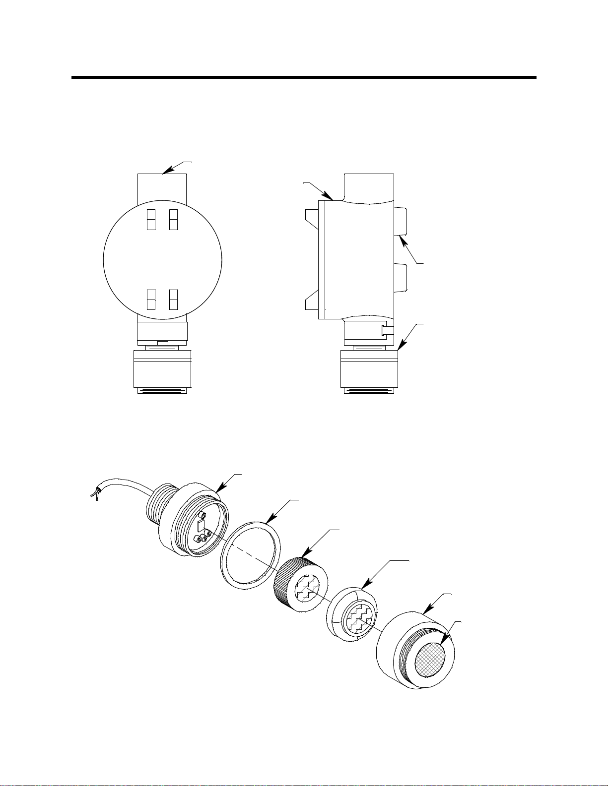
include a junction box. Figure 1 below shows the components of the 65-24 99RK.
3/4 NPT Conduit Hub
Junction Box
Rubber Spacer, 3X
CO Detector
Not e: The re is a two point
ter m inal st rip in si d e th e
junction boxfor detector
connections.
Figure 1: 65-2499RK Component Location
65-2496RK CO Detector
The 65-2496RK CO detector consists of the detector housing body, detector housing cap,
cap gasket, plug-in sensor, and the charcoal filter with rubber boot.
Detector Housing Body
Cap Gasket
CO Plug-in Sensor
Charcoal Filter
w/Rubber Boot
Detector
Housing Cap
Hydrophobic
Membrane
Figure 2: 65-2496RK CO Detector Component Location
2 • 65-2496RK/65-2499RK CO Det ector
Page 7

Detector Housing Body
The detector housing body protects the electronic components within the housing. Use the
mounting threads at the top of the housing to screw the CO detector into a 3/4” NPT hub.
Two wires extend from the top of the detector housing body. Use these wires to connect
the detector to a controller. One of the wires is black and one of the wires is red.
The housing body includes a four-socket pattern at the bottom of the housing body. The
plug-in sensor mates to this socket pattern. A pre-amplifier located between the so ckets
and the two wires conditions the sensor’s sig na l before the signal reaches the controller.
Housing Cap & Cap Gasket
The housing cap screws onto the detector housing. It retains the sensor and the rubber
boot with the charcoal filter and protects them from damage. A hydrophobic membrane
on the outside of the cap face keeps water and particulates away from the charcoal filter
and sensor face behind the cap. Unscrew the detector cap to access the charcoal filter and
sensor for maintenance or replacement. A cap gasket seals the interface between the
housing and cap.
Plug-In Sensor
The plug-in sensor is secured in the dete ctor assembly by the housing cap. Through a
series of chemical and electrical reactions, the sensor produces an electrical output that
corresponds to the detection range of the detector.
Charcoal Filter
The disc-shaped charcoal filter is secured to face of the CO sensor with a rubber boot. The
charcoal filter prevents interference gases such as hydrogen sulfide (H
S) and certain
2
hydrocarbons from producing false CO readings.
Junction Box
The junction box allows you to insta ll the CO detector at a mounting site that is remote
from a controller and protects the dete ctor wiring connections. Two conduit hubs allow
you to mount the CO detector to the junction box and connect the wiring from the
detector to a controller. Three spacers installed on the back of the junction box control the
distance of the junction box from a mounting surface and ensure that there is enough
room to install a calibration cup on the detector during calibration. A terminal block
within the junction box facilitates the w iring connections. A cover on the front of the
junction box allows access to the interior of the junction box.
65-2496RK/65-2499RK CO Det ec t or • 3
Page 8
Installation
This section describes procedures to mount the CO detector in th e monitoring
environment and wire the detector to a controller.
Mounting the CO Detector
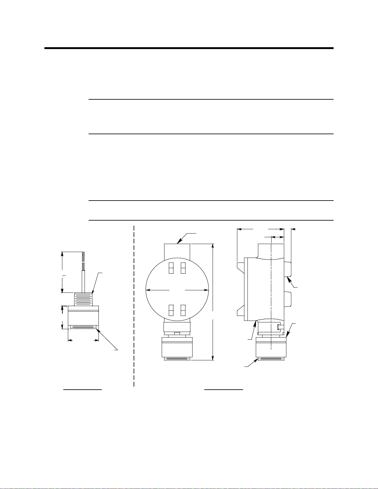
NOTE: If you are installing a 65-2496RK, it does not include a junction box and is usually
factory installed in one of a controller’s conduit hubs or may be field installed
using the 3/4” NPT threads on the end with the wir es. The 65-2499RK includes a
junction box as shown in Figure 3 below.
1. Select a mounting site that is representative of the monitoring environment. Consider
the following when you select the mounting site.
• Select a site where the detector is not likely to be bumped or disturbed. Ma ke sur e
there is sufficient room to perform start-up, maintenance, and calibration
procedures.
• Select a site where the target gas is likely to be found first.
+
7.30 .25
.75
1.32
1 1/2-20 Thread for
NOTE: If your application does not require a specific mounting site, mount the detector
at approximately breathing level.
.38
Rubber
Spacer, 3X
CO
Detector
3/4" NPT
Ø 1.75
Calibration Cup
3.65
3/4 NPT
Conduit Hub
6.80 Max
Junction
1 1/2-20 Thread for
Calibr ation Cup
2.70
.75
Box
65-2496RK
Figure 3: Outline & Mounting Dimensions, 65-2496RK & 65-2499RK
2. At the mounting site you select, hang or mount the junction box with the detector
facing down (see Figure 3).
4 • 65-2496RK/65-2499RK CO Det ector
65-2499RK
Page 9

Wiring the CO Detector to a Controller
WARNING: Always verify that power to the controller is OFF before you make wiring
connections.
1. Turn off the controller.
2. Turn off or unplug p ower to the controller.
3. If the detector is mounted remotely from a controller using the junction box, proceed
to step 4.
If the detector is mounted directly to a controller, it is normally factory wired. Confirm
that the detector’s black and red wires are connected to the appropriate controller
detector terminals and skip to “Start Up” on page 7. See Figure 4, the controller
operator’ s manual, and the controller’s detector head specification sheet for the 652496RK detector for the wiring connections.
4. Remove the junction box cover.
5. Guide a two-conductor, shielded cable or two wires in conduit through the unused
conduit hub of the junction box. Use appropriate conduit fittings and construction
technique for the environmental rating of the junction box. The junction box is rated
NEMA 4X.
6. Connect the two wires to the detector using the terminal block.
CAUTION: If using shielded cable, leave the drain wire insulated and disconne cted at the
detector. You will connect the opposite end of the cable’s drain wire at the controller.
7. Secure the junction box cover to the junction box.
8. Route the cable or wires leading from the CO detector through one of the conduit
hubs at the controller housing. Use appropriate conduit fitt ings and construction
technique for the environmental rating of the controller. RKI controllers are typically
rated NEMA 4X.
CAUTION: Do not route power and detector wiring through the same conduit hub. The power
cable may disru pt the transmission of the detect or signal to the controller.
9. Connect the wires to the applicable controller terminal strip. See the controller
operator’ s manual and the controller’s detector head specification sheet for the 652499RK detector.
65-2496RK/65-2499RK CO Det ec t or • 5
Page 10
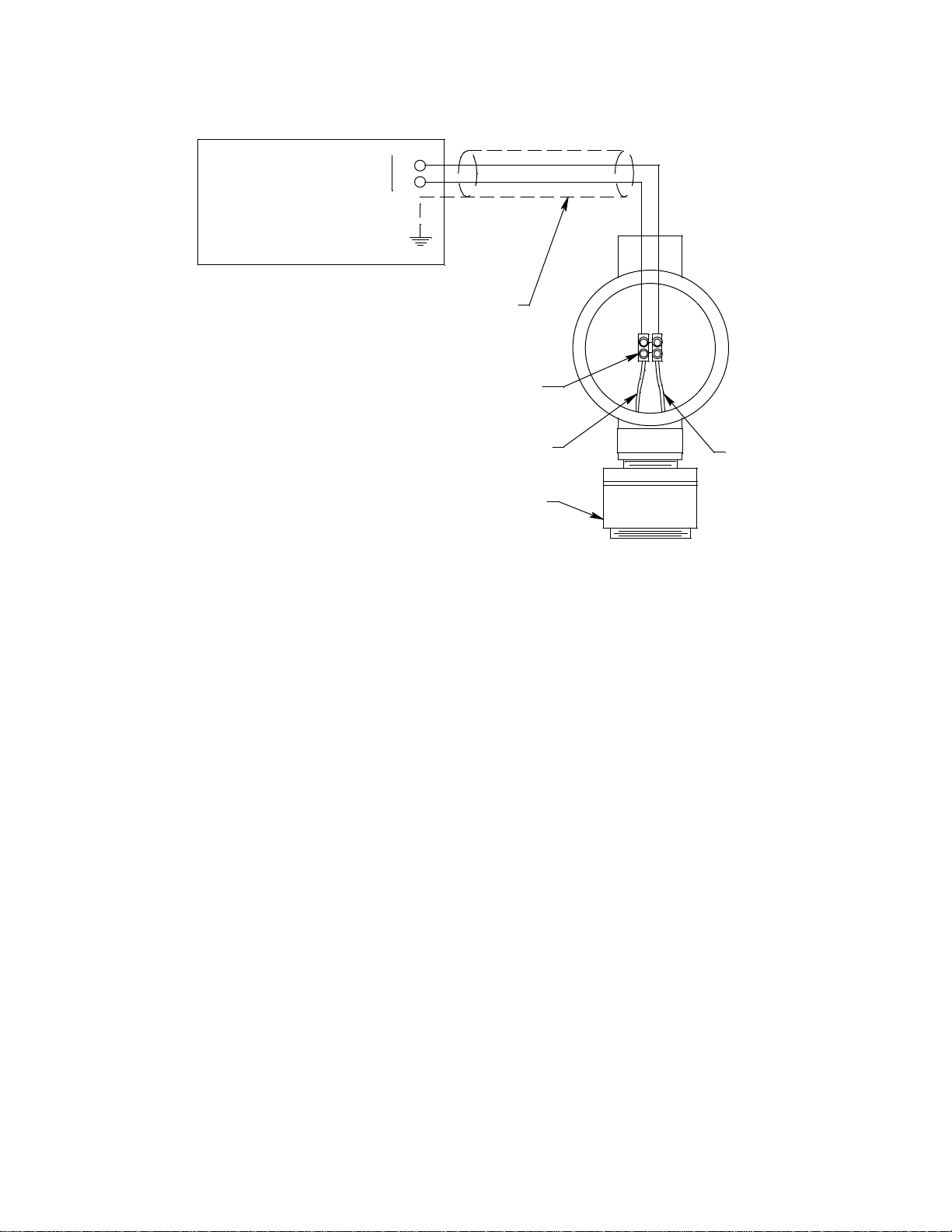
Controller Detector Terminals,
Ty pic a l Designations
Controller Ho u s ing
+
S
Shielded Cable
Te rminal S tri p
Black
CO Detector
Red
Figure 4: Wiring the CO Detector to a Controller
10. If using shielded cable, connect the cable’s drain wire to an available chassis ground at
the controller. RKI controllers typically have a ground stud that is a convenient
grounding location.
6 • 65-2496RK/65-2499RK CO Det ector
Page 11

Start Up
This section describes procedures to start up the CO detector and place the detector into
normal operation.
Introducing Incoming Power
1. Complete the installation procedures described earlier in this manual.
2. Verify that the power wiring to the controller is correct and secure. Refer to the
controller operator’s manual.
3. Turn on or plug in the incoming power, then turn on the controller.
4. Verify that the controller is on and operating properly. Refer to the controller
operator’s ma nual.
CAUTION: Allow the detector to warm up for 5 minutes before you continue with the next
section, “Setting t he Zero (Fresh Air) Reading”.
Setting the Zero (Fresh Air) Reading
CAUTION: If you suspect the presence of CO in the monitoring environment, use the calibration
kit and a zero air calibration cylinder to introduce “fresh air” to the CO de tector and
verify an accurate zero setting. See “Calibration” on page 13 for instructions to
introduce zero air to the CO detector.
1. Verify that the CO detector is in a fresh air environment (environment known to be
free of toxic and combustible gases, and of normal oxygen content, 20.9%).
2. Verify a reading of 0 p pm at the cont roller.
If the display reading is 0 ppm, start up is complete. The CO detector is in n ormal
operation. If the display reading is not 0 ppm, continue with step 3.
3. Perform a zero (fresh air) adjustment operation at the controller. See the controller
operator’s manual for instructions.
65-2496RK/65-2499RK CO Det ec t or • 7
Page 12

Maintenance
This section describes maintenance procedures. It includes preventive maintenance,
troubleshooting, and component replacement procedures.
Preventive Maintenance
This section describes a preventive maintenance schedule to ensure the optimum
performance of the CO detector. It includes daily, monthly, and quarterly procedures.
Daily
Verify a display reading of 0 ppm at the controller. Investigate significant changes in the
display reading.
Monthly
This procedure describes a test to verify that the CO detector responds properly to the
target gas. It describes the test using a calibration kit that includes a calibration cup,
calibration gas, sample tubing, and a fixed flow regulator with an on/off knob. RKI
Instruments, Inc. recommends using a 0.5 LPM (liters per minute) fixed flow regulator.
WARNING: Failure to use the recommended calibration gas flow rate will result in an
inaccurate r e ad in g.
NOTE: Performing a response test on the CO detector may cause alarms. Be sure to put
the controller into its calibration program or disable external alarms before
performing this test.
Preparing for the response test
1. Place the controller into its calibration program or disable external alarms.
2. Verify that the controller display reading for the channel you are testing is 0 ppm.
If the display reading is not 0 ppm, set the zero (fresh air) reading of the detector as
described in the Start Up section of this manual, then continue this procedure.
3. Screw the regulator into the calibration cylinder. Make sure the regulator is off. It is off
when the on/off knob is turned all the way clockwise.
4. Screw the calibration cup onto the bottom of the CO detector.
5. Use the sample tubing to connect the regulator to the calibration cup.
Performing the response test
1. Turn the regulator’s on/off knob counterclockwise to open the regulator. Gas will
begin to flow.
2. Allow the gas to flow for two minutes, then verify that the reading is within ± 20% of
the cylinder gas concentration.
NOTE: If the reading is not within ± 20% of the correct response reading, calibrate the
detector as described in “Calibration” on page 13.
3. Turn the regulator’s on/off knob clockwise to close the regulator.
4. Unscrew the regulator from the calibration cylind er.
8 • 65-2496RK/65-2499RK CO Det ector
Page 13

5. Unscrew the calibration cup from the CO detector. Make sure that you do not loosen
the detector housing cap when you unscrew the calibration cup.
6. When the controller display reading falls below th e alarm setpoints, return the
controller to normal operation.
Quarterly
Calibrate the CO detector as described in “Calibration” on page 13.
Troubleshooting
The troubleshooting guide describes symptoms, probable causes, and recommended
action for problems you may encounter with the CO detector.
NOTE: This troubleshooting guide describes detector problems only. See the controller
operator’s manual for problems you may encounte r with the controller.
Fail Condition
Symptoms
• The controller indicates a fail condition.
Probable causes
• The detector wiring is disconnected or misconnected.
• The plug-in sensor is not properly plugged into the four-socket pattern in the detector
housing body.
• The detector’s zero reading is low enough to cause a fail condit ion.
• The detector is malfunctioning.
Recommended action
• Verify that the detecto r wirin g is co rrect and secure.
• Confirm that the p lug-in sensor is installed properly.
• Perform a zero (fresh air) adjustment. A full calibration is recommended.
• If the fail condition continues, replace the plug-in sensor a s d e scribe d later in this
section.
• If the fail condition continues, contact RKI Instruments, Inc. for further instruction.
Slow or No Response/Difficult or Unable to Calibrate
Symptoms
• The detector responds slowly or doe s not respond during the monthly response test.
• Unable to accurately set the zero or response reading during the calibration
procedure.
• The detector requires frequent calibration.
NOTE: Under “normal” circumstances, the detector requires calibration once every three
months. Some applications may require a more frequent calibration schedule.See
“Calibration Frequency” on page 13 for a discussion of the calibration frequency.
65-2496RK/65-2499RK CO D e te c to r • 9
Page 14

Probable causes
• The plug-in sensor has been replaced and the shorting jumper has not been removed.
• The calibration cylinder is low, out-dated, or defective.
• The incorrect calibration cup or regulator is being used.
• The membrane on the detector housing cap is blocked with dirt or some other
particulate contamination.
• The detector is malfunctioning.
Recommended action
1. Confirm that the shorting jumper on the plug-in sensor pins has been removed.
2. Ver if y that the cal i brat i on cylind er con tai ns an adequate supply of a fresh te st sa mpl e.
3. Confirm that you are using the correct calibration cup and regulator. See “Parts List”
on page 15 for the required calibration cup and regulator.
4. Check the face of the detector housing cap and remove any particulate contamination
from the hydrophobic membrane if necessary. If the membrane appears saturated
with contamination or damaged, replace the membrane as described in “Replacing
the Hydrophobic Membrane” on page 12.
5. If the calibration/response difficulties continue, replace the plug-in sensor as
described later in this section.
6. If the calibration/response difficulties continue, contact RKI Instruments, Inc. for
further instruction.
Unexplained Gas Readings
Symptom
• The display indicates a CO reading when CO is known not to be present.
Probable causes
• The detector needs calibration.
• The charcoal filter on the plug-in sensor is saturated and is no longer scrubbing out
H
S or hydrocarbons that cause a response on the CO sensor.
2
Recommended action
1. Calibrate the detector as described in “Calibration” on page 13.
2. If the difficulties continue, replace the charcoal filter as described later in this section.
3. If the difficulties continue, replace the plug-in sensor as described later in this section.
4. If the difficulties continue, contact RKI Instruments, Inc. for further instruction.
Replacing Components of the CO Detector
This section includes a procedure to replace the plug-in CO sensor, one to replace the
charcoal filter , one to replace the hydrophobic membrane, and one to replace the entire CO
detector assembly. In most cases, it is not necessary to replace the entire detector assembly.
Replacing The Plug-in CO Sensor
CAUTION: The plug-in sensor contains electrolyte which is a dilute acid. Do not disassemble the
sensor when replacing it with a new one. If sensor electrolyte comes in contact with
your skin, wash affected area thoroughly with soap and water.
1. Turn off the controller.
10 • 65-2496RK/65-2499RK CO Det ector
Page 15

2. Turn off or unplug p ower to the controller.
3. Unscrew the detector housing cap from the detector housing body.
4. Unplug and remove the old CO sensor with the boot and charcoal filter attached.
5. Remove the rubber boot and charcoal filter from the old CO sensor.
6. Remove th e replacement CO sensor from its packaging and remove the wire jumper
that is shorting the WE and RE sensor pins. This wire jumper is installed on the sensor
pins for shipment or storage but must be removed for the sensor to operate properly
when installed in a detector.
WARNING: The CO sensor will not operate properly if the wire jumper is not removed.
7. Install the rubber boot with charcoal filter onto the replacement sensor’s face.
8. Carefully plug the replacement sensor into the four-socket pattern that is located in
the detector housing body.
WARNING: You must replace the plug-in sensor with the same type of sensor that is
installed. A detector cannot be converted from one type of detector to
another by using a different plug-in sensor. For example, if you are
replacing an CO sensor, you must replace it with a CO sensor.
9. Make sure the cap gasket is in place and screw the detector housing cap back onto the
detector housing body.
10. Turn on power to the controller.
11. Turn on the controller.
CAUTION: Allow the replacem ent sens or to warm up for 5 minutes before you continue with the
next step.
12. Calibrate the detector as described in “Calibration” on page 13.
Replacing the Charcoal Filter
1. Turn off the controller.
2. Turn off or unplug p ower to the controller.
3. Unscrew the detector housing cap from the detector housing body.
4. Unplug and remove the CO sensor with the boot and charcoal filter attached.
5. Remove the rubber boot that secures the charcoal filter to the CO sensor.
6. Remove the charcoal filter from the rubber boot.
7. Place the replacement filter in the rubber boot in the same position as the filter you
removed in the previous step.
8. Reinstall t he rubber boot wi t h charcoal filter on the CO sensor.
9. Carefully plug the replacement sensor into the socket pattern that is located in the
detector housing body.
10. Make sure the cap gasket is in place and screw the detector housing cap back onto the
detector housing body.
11. Turn on power to the controller.
65-2496RK/65-2499RK CO D et ec t or • 11
Page 16

12. Turn on the controller.
Replacing the Hydrophobic Membrane
1. Turn off the controller.
2. Turn off or unplug incoming power to the controller.
3. Unscrew the detector housing cap from the detector housing body.
4. Gently pry up the edge of the white hydrophobic mem b rane with a small flat blade
screwdriver or a similar tool.
5. Peel off the hydrophobic membrane. It may be necessary to clean off the detector
housing cap face to remove any residue left from the adhesive backed membrane.
6. Install the new membrane in t he recess on the face of the detector housing cap.
7. Make sure the cap gasket is in place and screw the detector housing cap back onto the
detector housing body.
8. Turn on power to the controller.
9. Turn on the controller.
Replacing the CO Detector
NOTE: In most cases, it is only necessary to replace the plug-in sensor.
1. Turn off the controller.
2. Turn off or unplug incoming power to the controller.
3. If the detector is installed directly on a controller, open the controller door.
If the detector is installed remotely from a controller in a junction box, remove the
junction box cove r.
4. If the detector is installed directly on a controller, disconnect the detector leads from
the detector terminal strip in the controller. Note the position of the color-coded leads
as you remove them.
If the detector is installed remotely from a controller in a junction box, disconnect the
detector leads from the terminal block in the junction box. Note the position of the
color-coded leads as you remove them.
5. Unscrew the detector from the controller conduit hub or junction box conduit hub.
6. Gu ide the detector leads of the replacement detector through the controller conduit
hub or junction box conduit hub, then screw the mounting threads of the detector into
the hub. If necessary for environmental conditions, apply thread sealant or teflon tape
to the hub and/or detector threads to seal them.
7. If the detector is installed directly on a controller, connect the detector leads to the
appropriate detector terminal strip terminals. See Figure 4 on page 6 for wiring to a
generic controller. See the controller operator’s manual and the controller’s detector
head specification sheet for the 65-2496RK detecto r for wiring specific to your
controller.
If the detector is installed remotely from a controller in a junction box, connect the
detector leads to the terminal block the same way the old detector was wired (see
Figure 4 on page 6). See the controller operator’s manual and the controller’s detector
head specification sheet for the 65-2499RK detector to verify the connections to the
controller are correct.
12 • 65-2496RK/65-2499RK CO Det ector
Page 17

8. If the detector is installed remotely from a controller in a junction box, reinstall the
junction box cove r.
9. Turn on or plug in power to the controller.
10. Turn on the controller.
CAUTION: Allow the replacement detector to warm up for 5 minutes before y o u c o ntinue with
the next step.
11. Calibrate the replacement detector as described in “Calibration” on page 13.
Calibration Frequency
Although there is no particular calibration frequency that is correct for all applications, a
calibration frequency of every 3 months is adequate for most CO detector applications.
Unless experience in a particular application dictates otherwise, RKI Instruments, Inc.
recommends a calibration frequency of every 3 months for the CO detector.
If an application is not very demanding, for example detection in a clean, temperature
controlled environment where CO is not normally present, and calibration adjustments
are minimal at calibration, then a calibration frequency of every 6 months is adequate.
Calibration
If an application is very demanding, for example if the environment is not well controlled
or if CO is often present, then more frequent calibration than every 3 months may be
necessary.
This section describes how to calibrate the CO detector. It includes procedures to prepare
for calibrat ion, set the fresh air re ading, set the response reading, and return to norma l
operation. It describes calibration using a calibration kit that includes a calibration cup,
calibration gas, sample tubing, and a fixed flow regulator with an on/off knob. RKI
Instruments, Inc. recommends using a 0.5 LPM (liters per minute) fixed flow regulator.
WARNING: Not using the recommended calibration cup and sample flowrate will
result in an inaccurate calibration. See“Parts List” on page 15 for the
required calibration cup and regulator.
Prepari ng for Ca libration
1. Screw the calibration cup onto the bottom of the CO detector.
2. Screw the regulator into the zero air calibration cylinder. Make sure the regulator is
off. It is off when the on/off knob is turned all the way clockwise.
3. Use the sample tubing to connect the regulator to the calibration cup.
NOTE If you can verify that the CO detector is in a fresh air environment, you do not
need to apply zero air to the detector before adjusting the fresh air reading.
4. Put the controller into its calibration program. See the controller operator’s manual
for instructions to enter the calibration program.
65-2496RK/65-2499RK CO D et ec t or • 13
Page 18

Setting the Zero (Fresh Air) Reading
1. Follow the instructions in the controller operator’s manual for setting the zero
reading.
2. When the instructions call for applying z e ro air to the detector, turn the regulator’s
on/off knob counterclockwise to open it. Gas will begin to flow.
3. Allow the gas to flow for two minutes.
4. Set the fresh air reading according to the controller operator’s manual.
5. Turn the regulator’s on/off knob clockwise to close it.
6. Unscrew the regulator from the zero air calibration cylinder. Leave the sample tubing
connected to the regulator and the calibration cup.
NOTE: Depending on the size of your zero air cylinder, it is possible that you will have a
different regulator for the zero air cylinder and the CO gas cylinder. If necessary
to fit the CO calibration gas cylinder, change the regulator.
Setting the Response Reading (Span)
1. Screw the regulator into the calibration gas cylinder. Make sure the regulator is off. It
is off when the on/off knob is turned all the way clockwise.
2. Follow the directions in the controller operator’s manual for setting the response
(span) reading.
3. When the instructions call for exposing the detector to gas, turn the regulator’s on/off
knob counterclockwise to open it. Gas will begin to flow.
4. Allow the gas to flow to the detector for 2 minutes.
5. Set the response reading according to the controller operator’s manual.
6. After setting the response reading, turn the regulator’s on/off knob clockwise to turn
it off.
7. Unscrew the regulator from the cylinder.
8. Unscrew the calibration cup from the CO detector. Make sure that you do not loosen
the detector housing cap when you unscrew the calibration cup.
NOTE: For convenience, leave the regulator and calibration cup connected by the
sample tubing.
Returning to Normal Operation
1. Allow about 45 seconds for the gas reading to decrease below the alarm points and
then return the controller to normal operation.
NOTE: If you do not allow the gas reading to decrease below the alarm points, then
unwanted alarms may occur.
2. Verify that the controller display reading decreases and stabilizes a t 0 ppm.
3. Store the components of the calibration kit in a safe and convenient place.
14 • 65-2496RK/65-2499RK CO Det ector
Page 19

Parts List
Table 2 lists replacement parts and accessorie s fo r the CO detector.
Table 2: Parts List
Part Number Description
06-1248RK-03 3 foot length of sample tubing for calibration kit
07-0039RK Detector housing cap gasket
07-0203RK Rubber retaining boot (for charcoal filter)
33-0157RK Hydrophobic membrane, adh e sive backed, for detector housing cap
33-7101RK Charcoal Filter Disk
65-2496RK CO replacement detector assembly (includes plug-in sensor)
71-0156RK 65-2496RK/65-2499RK CO Detector Operator’s Manual (this document)
81-0064RK Calibrat ion cylinder,50 PPM CO in air; 17 liter steel
81-0064RK-01 Calibration cylinder, 50 PPM CO in air; 34 liter steel
81-0064RK-03 Calibration cylind er, 50 PPM CO in air; 103 liter steel
81-0076RK Zero air calibration cylinder, 17 liter steel
81-0076RK-01 Zero air calibration cylinder, 34 liter steel
81-0076RK-03 Zero air calibration cyl i nd er, 103 liter steel
81-1050RK Regulator with gauge and knob, 0.5 LPM, for 17 liter and 34 liter steel
calibration cylinders
81-1051RK Regulator with gauge and knob, 0.5 LPM, for 34AL/58/103 liter cali-
bration cylinders
81-1117RK Calibration c u p
ES-1531-CO CO replacement sensor
65-2496RK/65-2499RK CO D et ec t or • 15
 Loading...