

Page 1

Part Number: 71-0204RK
Revision: B
65-2481RK
Multi Point Detector
Operator’s Manual
Released: 7/18/14
RKI Instruments, Inc.
www.rkiinstruments.com
Page 2

WARNING
Read and understand this instruction manual before operating
detector . Improper use of the dete ctor could result in bodily harm
or death.
Periodic calibration and maintenance of the detector is essential
for proper operation and correct readings. Please calibrate and
maintain this detector regularly! Frequency of calibration
depends upon the type of use you have and the sensor types.
T ypical calibration frequencies for most applications a re between
3 and 6 months, but can be required more often or less often
based on your usage.
65-2481RK Multi Point Detec tor
Page 3

Product Warranty
RKI Instruments, Inc. warrants gas alarm equipment sold by us to be free from defects in
materials, workmanship, and performance for a period of one year fr o m date of shipment
from RKI Instruments, Inc. Any parts found defective withi n tha t period will be repaired
or replaced, at our option, free of charge. This warranty does not apply to those items
which by their nature are subject to deterioration or consumption in normal ser v ice, and
which must be cleaned, repaired, or replaced on a routine basis. Examples of such items
are:
W arranty is voided by abuse including mechanical damage, alteration, rough handling, or
repair procedures not in accordance with the operator’s manual. This warranty indicates
the full extent of our liability , a nd we are not r esponsible for removal or r eplacement costs,
local repair costs, transportation costs, or contingent expenses incurred without our prior
approval.
a) Absorbent cartridges d) Batteries
b) Pump diaphragms and valves e) Filter elements
c) Fuses
THIS WARRANTY IS EXPRESSLY IN LIEU OF ANY AND ALL OTHER
WARRANTIES AND REPRESENTATIONS, EXPRESSED OR IMPLIED,
AND ALL OTHER OBLIGATIONS OR LIABILITIES ON THE PART OF
RKI INSTRUMENTS, INC. INCLUDING BUT NOT LIMITED TO, THE
WARRANTY OF MERCHANTABILITY OR FITNESS FOR A
PARTICULAR PURPOSE. IN NO EVENT SHALL RKI INSTRUMENTS,
INC. BE LIABLE FOR INDIRECT, INCIDENTAL, OR CONSEQUENTIAL
LOSS OR DAMAGE OF ANY KIND CONNECTED WITH THE USE OF
ITS PRODUCTS OR FAILURE OF ITS PRODUCTS TO FUNCTION OR
OPERATE PROPERLY.
This warranty covers instruments and parts sold to users by authorized distributors,
dealers, and representatives as appointed by RKI Instruments, Inc.
We do no t as su me indemnif ic a t ion for any accident or d amage caused b y t he op e r a t ion of
this gas monitor, and our warranty is limited to the replacement of parts or our complete
goods.
65-2481RK Multi Point Detector
Page 4

Table of Contents
Overview . . . . . . . . . . . . . . . . . . . . . . . . . . . . . . . . . . . . . . . . . . . . . . . . . . . . . . . . . . . . . . . . . . . 1
Specifications. . . . . . . . . . . . . . . . . . . . . . . . . . . . . . . . . . . . . . . . . . . . . . . . . . . . . . . . . . . . . . . . 1
Description. . . . . . . . . . . . . . . . . . . . . . . . . . . . . . . . . . . . . . . . . . . . . . . . . . . . . . . . . . . . . . . . . . 3
Detectors. . . . . . . . . . . . . . . . . . . . . . . . . . . . . . . . . . . . . . . . . . . . . . . . . . . . . . . . . . . . . . . . . . . . . . . . . . . . . 3
Conduit Seal . . . . . . . . . . . . . . . . . . . . . . . . . . . . . . . . . . . . . . . . . . . . . . . . . . . . . . . . . . . . . . . . . . . . . . . . . 8
Junction Box. . . . . . . . . . . . . . . . . . . . . . . . . . . . . . . . . . . . . . . . . . . . . . . . . . . . . . . . . . . . . . . . . . . . . . . . . . 8
Installation . . . . . . . . . . . . . . . . . . . . . . . . . . . . . . . . . . . . . . . . . . . . . . . . . . . . . . . . . . . . . . . . . . 8
Mounting the Multi-Point Detector . . . . . . . . . . . . . . . . . . . . . . . . . . . . . . . . . . . . . . . . . . . . . . . . . . . . . . 8
Wiring the Multi-Point Detector to a Controller . . . . . . . . . . . . . . . . . . . . . . . . . . . . . . . . . . . . . . . . . . 11
Startup. . . . . . . . . . . . . . . . . . . . . . . . . . . . . . . . . . . . . . . . . . . . . . . . . . . . . . . . . . . . . . . . . . . . . 14
Introducing Incoming Power . . . . . . . . . . . . . . . . . . . . . . . . . . . . . . . . . . . . . . . . . . . . . . . . . . . . . . . . . . 14
Setting the Zero (Fresh Air) Reading. . . . . . . . . . . . . . . . . . . . . . . . . . . . . . . . . . . . . . . . . . . . . . . . . . . . 14
Maintenance. . . . . . . . . . . . . . . . . . . . . . . . . . . . . . . . . . . . . . . . . . . . . . . . . . . . . . . . . . . . . . . . 15
Preventive Maintenance . . . . . . . . . . . . . . . . . . . . . . . . . . . . . . . . . . . . . . . . . . . . . . . . . . . . . . . . . . . . . . 15
Troubleshooting . . . . . . . . . . . . . . . . . . . . . . . . . . . . . . . . . . . . . . . . . . . . . . . . . . . . . . . . . . . . . . . . . . . . . 17
Replacing Components of the Multi-Point Detector. . . . . . . . . . . . . . . . . . . . . . . . . . . . . . . . . . . . . . . 18
Calibration, LEL, H2S and CO Detectors . . . . . . . . . . . . . . . . . . . . . . . . . . . . . . . . . . . . . . . 23
Preparing for Calibration. . . . . . . . . . . . . . . . . . . . . . . . . . . . . . . . . . . . . . . . . . . . . . . . . . . . . . . . . . . . . . 23
Setting the Zero Reading. . . . . . . . . . . . . . . . . . . . . . . . . . . . . . . . . . . . . . . . . . . . . . . . . . . . . . . . . . . . . . 24
Setting the Response Reading. . . . . . . . . . . . . . . . . . . . . . . . . . . . . . . . . . . . . . . . . . . . . . . . . . . . . . . . . . 24
Returning to Normal Operation. . . . . . . . . . . . . . . . . . . . . . . . . . . . . . . . . . . . . . . . . . . . . . . . . . . . . . . . 24
Calibration, Oxygen Detector. . . . . . . . . . . . . . . . . . . . . . . . . . . . . . . . . . . . . . . . . . . . . . . . . 25
Preparing for Calibration. . . . . . . . . . . . . . . . . . . . . . . . . . . . . . . . . . . . . . . . . . . . . . . . . . . . . . . . . . . . . . 25
Setting the Fresh Air Reading. . . . . . . . . . . . . . . . . . . . . . . . . . . . . . . . . . . . . . . . . . . . . . . . . . . . . . . . . . 25
Setting the Zero Reading. . . . . . . . . . . . . . . . . . . . . . . . . . . . . . . . . . . . . . . . . . . . . . . . . . . . . . . . . . . . . . 26
Returning to Normal Operation. . . . . . . . . . . . . . . . . . . . . . . . . . . . . . . . . . . . . . . . . . . . . . . . . . . . . . . . 26
Parts List . . . . . . . . . . . . . . . . . . . . . . . . . . . . . . . . . . . . . . . . . . . . . . . . . . . . . . . . . . . . . . . . . . . 27
65-2481RK Multi Point Detec tor
Page 5

Overview
This manual describes the 65-2481RK multi point direct connect detector. This manual
also describes how to install, start up, maintain, and calibrate the detector when it is used
with a gas monitoring controller. A parts list at the end of this manual lists replacement
parts and accessories for the detector.
Specifications
WARNING: Do not use this product in a manner not specified in thi s instruction
manual.
Table 1 lists specifications for the multi-point detect or.
Table 1: Specifications
Target Gas 65-2481RK: LEL/O
S/CO, methane calibration standard for
2/H2
LEL
65-2481RK-01: LEL (IR CH
)/O2/H2S/CO, methane calibration
4
for LEL
65-2481RK-02: LEL (IR HC)/O
S/CO, propane calibration for
2/H2
LEL
*Note: Since the 65-2481RK is a direct connect detector, the
calibration is done at the controller.
Area Classification Explosion proof for Class I, Groups B, C, and D
Sampling Method Diffusion
Detection Range LEL: 0 to 100 %LEL (lower explosive limit)
: 0 to 25 %volume
O
2
H
S: 0 to 100 ppm (parts per million)
2
CO: 0 to 300 ppm (parts per million)
Response Time 90% in 30 seconds
Accuracy Catalytic Combustible Gas
:
± 5% of reading or ± 2% LEL (whichever is greater)
IR Combustible Gas
:
± 5% of reading or ± 2% of full scale (whichever is greater)
Oxygen
± 0.5% O
:
2
Hydroge n Sulfide:
± 5% of reading or ± 2 ppm H2S (whichever is greater)
Carbon Monoxide
:
± 5% of reading or ± 5 ppm CO (whichever is greater)
Operating Temperature 23°F to 104°F (-5°C to 40°C)
65-2481RK Multi Point Detector • 1
Page 6

NOTE: The following symbol on the detector label is a caution to the user to refer to this
!
documentation for installation and operation instructions:
W ARNING: When using the 65-2481RK, you must follow the instructions and warnings
in this manual to assure proper and safe operation of the 65-2481RK and to
minimize the risk of personal injury. Be sure to maintain and period ically
calibrate the 65-2481RK as described in t hi s manual.
2 • 65-2481RK Multi Po int Detector
Page 7
Description
This section describes the multi-point detector. It consists of the detectors, the terminal
strips, the conduit seal, and the junction boxes.
Detectors
This section describes the components of the various detectors that are used with each
model of the 65-2481RK.
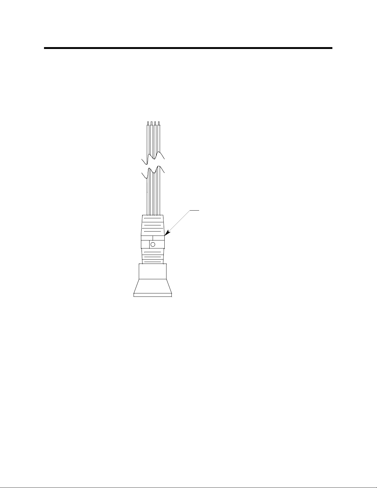
61-0140RK LEL Detector
LEL Detector
Figure 1: 61-0140RK LEL Detector Component Location
The combustible gas detector is a catalytic type detector that produces an electrical output
that corresponds to the detection range. It is packaged in a 1/2 inch NPT nipple with a
sintered metal flame arrestor on one end allowing ambient air to diffuse into the detector.
The flame arrest or al so co ntai n s any s park s whi ch may occur within the detect or. The 1/2
inch NPT mounting threads at the top of the detector allow you to install it in the bottom
conduit hub of the junction box with the use of a 3/4 in. x 1/2 in. NPT reducer. A
rainshield screws onto the bottom of the detector (flame arrestor end). The rainshield
helps protect the detector from rain and debris in the monitoring environment. Four colorcoded leads extend from the top of the detector. The leads allow you to connect the
detector to the terminal block.
65-2481RK Multi Point Detector • 3
Page 8
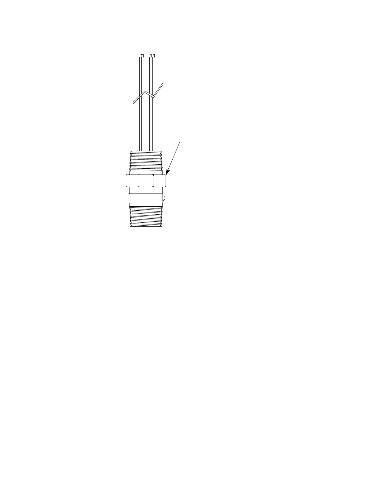
61-0190RK IR LEL Detector
IR LEL Detector
Figure 2: 61-0190RK IR LEL Detector Component Location
The infrared LEL detector is made up of a miniature infrared combustible gas LEL
detector housed and encapsulated in a pipe nipple. The pipe nipple has 3/4” NPT thr eads
on each end and a 1 1/4” hex that allows removal or installation of the detector with a
wrench. A por ous flame arr e stor t hat is coat ed wit h a hydr o phobic f ilm that re pels liquids
is on one end of the detector and allows sample gas to enter the detector. The flame
arrestor also contains any sparks which may occur within the detector. Four color coded
leads, red, white, green, and black, extend from the other end of the detector. The leads
allow you to connect the detector to the terminal block. To distinguish the propane
detector from the methane detector (in case the replacement sensor label that is applied to
one of the leads is lost), a short length of red shrink tubing is ap plied to the white wire of
the propane detector near where the wire comes out of the nipple.
4 • 65-2481RK Multi Po int Detector
Page 9
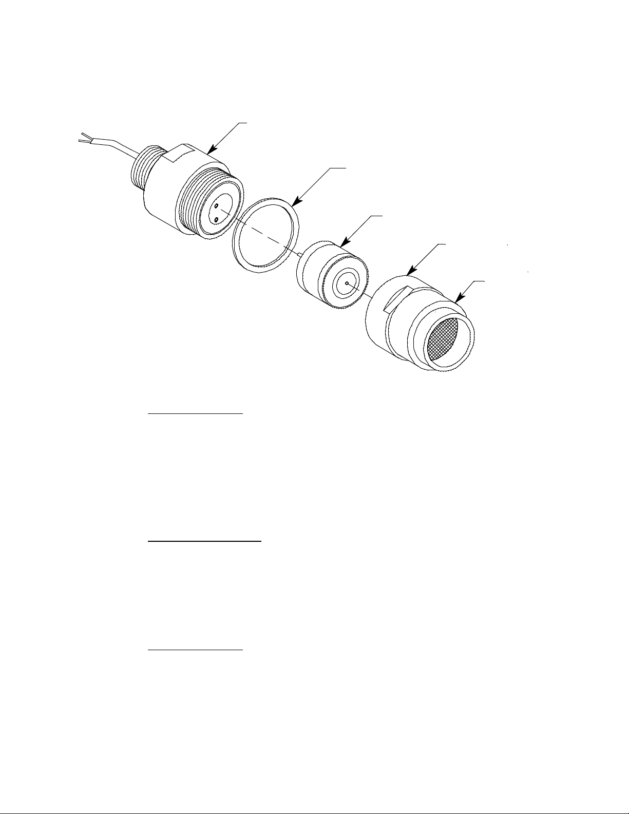
Oxygen Detector
The detector consists of the oxygen sensor, the detector housing body, detector housing
cap, and cap gasket.
Detector Housing Body
Cap Gasket
Plug-in Oxygen Sensor
Detect or Housing Cap
Flame Arrestor
Guard
Figure 3: Oxygen Detector Component Location
Detector Housing Body
The detector housing body protects the electronic components within the housing. Use the
mounting threads at the top of the housing to screw the oxygen detector into the 3 /4”
NPT hub on the bottom of the junction box. Two wires extend from the top of the detector
housing body . Use these wires to connect the oxygen detector to the terminal block. One of
the wires is white and one of the wires is green.
The housing includes two sockets installed on a circuit board. These sockets accept the
plug-in sensor’s two pins to provide electrical connection for the sensor. The circuit board
with the sockets conditions the sensor’s signal before the signal reaches the controller.
Housing Cap & Cap Gasket
The housing cap screws onto the detector housing. It retains the plug-in sensor and
protects it from damage. A foam gasket is installed inside the ho using cap that seals
against the sensor face. The housing cap also includes a flame arrestor which contains any
sparks that may occur within the detector and a flame arrestor guard which protects the
flame arrestor from damage. Unscrew the detector cap to access the plug-in sensor for
maintenance or replacement. A cap gasket seals the interface between the housing and
cap.
Plug-in Oxygen Sensor
The plug-in sensor is secured in the detector assembly by the housing cap. It has two pins
that mate with the sockets in the detector housing body. Through a series of chemical and
electrical reactions, the sensor produces an electrical output that corresponds to the
detection range of the transmitter.
65-2481RK Multi Point Detector • 5
Page 10
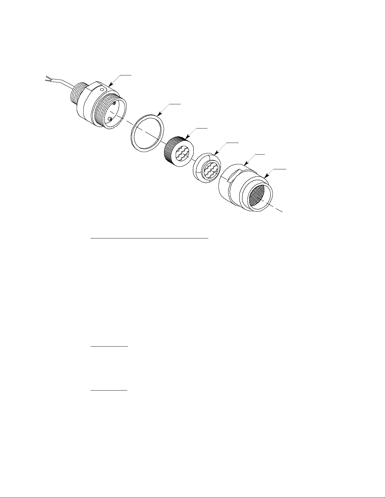
CO Detector
The detector consists of the CO sensor, charcoal filter with rubber boot, detector housing
body, detector housing cap, and cap gasket.
Detector Housing Body
Cap Gasket
Plug-In C O S ensor
Rubber Boot Wit h
Charcoal Filter
Detector Housing Cap
Flame Arrestor
Guard
Figure 4: CO Detector Component Loca tion
Detector Housing, Housing Cap, & Cap Gasket
The detector housing body protects the sensing components within the housing. Use the
3/4” NPT mounting threads at the top of the housing to screw the CO detector into the
bottom conduit hub of the junction box. Use the removable cap near the bottom of the
housing to access the sensor for maintenance or replacement. The cap protects the sensor
from damage and includes a flame arrestor which contains any sparks which may occur
within the detector housing. A cap gasket seals the interface between the housing and cap.
A flame arrestor guard is permanently bonded to the cap.
Two wires extend from the top of the detector housing body. Use these wires to connect
the CO detector to the multi-point detector. The housing includes a four-socket pattern.
This socket pattern accepts the sensor ’s four pins to secure the sensor within the detector
housing. A pre-amplifier, located between the sockets and two interconnect wires,
conditions the sensor’s signal before the signal reaches the controller.
Plug-In Sensor
The sensor is secured within the sensor housing by the housing cap. It has four pins that
mate with the sockets in the detector housing body. Through a series of chemical and
electrical reactions, the sensor produces an electrical output that corresponds to the
detection range of the detector.
Charcoal Filter
The disc-shaped charcoal filter is secured to the face of the CO sensor with a rubber boot.
The charcoal filter prevents interference gases (hydrogen sulfide [H
S] and certain
2
hydrocarbons) from producing false CO readings.
6 • 65-2481RK Multi Po int Detector
Page 11

H2S Detector
r
The detector consists of the detector housing body, detector housing cap, cap gasket,
rubber boot, spacer, and H
Detector Housing Body
S sensor.
2
Cap Gasket
H2S Plug-inSensor
Spacer
Rubber Boot
Detector
Housing Cap
Flame
Arresto
Guard
Figure 5: H
Detector Housing, Housing Cap, & Cap Gasket
S Detector Component Location
2
The detector housing protects the sensing components within the housing. Use the
mounting threads at the top of the housing to screw the H
S detector into a 3/ 4” NPT hub.
2
Use the removable cap near the bottom of the housing to access the sensor for
maintenance or replacement. The cap protects the sensor from damage and includes a
flame arrestor which contains any sparks which may occur within the detector housing. A
cap gasket seals the interface between the housing and cap. A flame arrestor guard is
permanently bonded to the cap.
Two wires extend from the top of the detector housing. Use these wires to connect the H
2
detector to the multi-point detector. The housing includes a four-socket pattern. This
socket pattern accepts the sensor’s four pins to secure the sensor with in the detector
housing. A pre-amplifier, located between the sockets and two interconnect wires,
conditions the sensor’s signal before the signal reaches the controller.
Rubber Boot and Spacer
A rubber boot and spacer are installed between the detector housing cap and the sensor.
They help ensure that the detector remains plugged into the detector housing body.
Sensor
The sensor is secured within the sensor housing by the detector housing cap. It has four
pins that mate with the sockets in the detector housing body . Thr ough a series of chemical
and electrical reactions, the sensor produces an electrical output that is proportional to the
detection range of the detector.
S
65-2481RK Multi Point Detector • 7
Page 12

Installation
Conduit Seal
The conduit seal isolates the volumes of the 2 junction boxes and preserves the explosion
proof classification of each junction box.
Junction Boxes
Use the junction boxes to install the mu lti-point detector at a mounting site that is remote
from the controller. The junction boxes protect the terminal strips and wiring connections
made to the terminal strips. Use the top 3/4’’ conduit hub to connect wiring from the
terminal strips to the controller. Use the cover on the front of the junction boxes to access
the interior of the junction boxes. The detectors and terminal strips are factory installed in
the junction boxes.
This section describes procedures to mount the multi-point detector in the monitoring
environment and wire the detector to a controller.
Mounting the Multi-Point Detector
1. Select a mounting site that is representative of the monitoring environment. Consider
the following when you select the mounting site.
• Select a site where the detector is not likely to be bumped or disturbed. Ma ke sur e
there is sufficient room to perform start-up, maintenance, and calibration
procedures.
• Select a site where the target gases are likely to be found first.
8 • 65-2481RK Multi Po int Detector
Page 13

0
.20 DIA X .45 Slot, (2X), mounti ng
7.75
3.15
2.40
3/4 NPT Hubs (4 X )
3.11
.25
1.25
19.0 Max.
H2S Detector
LEL Detector
CO Detector
Cond uit Seal
3.0
3.0
3/4" NPT Nip ple(2X)
Oxygen Det ector
Figure 6: Outline & Mounting Dimensions 65-2481RK
1.1
65-2481RK Multi Point Detector • 9
Page 14

0
19.0 Max.
3/4 NPT
Hubs (4X)
H2S Detector
Conduit Seal
1.25
7.75
3.15
2.40
Ø .20 X .45 Slot,(2X), mounting
3.11
.25
CO Detector
3/4" N PT Nippl e(2X)
IR L EL
Detector
Figure 7: Outline and Mounting Dimensions 65-2481RK-01 and 65-2481RK-02
2. At the mounting site you select, use #10 screws to mount the detector to a vertical
surface.
CAUTION: Mount the multi-point detector with the detectors facing down (see Figures 6-7).
NOTE: If your application does not require a specific mounting site, mo unt the detector
at approximately breathing level.
10 • 65-2481RK Multi Point Detector
3.0
3.0
Oxygen
Detector
1.1
Page 15

Wiring the Multi-Point Detector to a Controller
WARNING: Always verify that the power source is OFF bef ore you make wiring
connections.
1. Turn off the controller.
2. Turn off or unplug p ower to the controller.
3. Remove the junction box cover from the top junction box.
WARNING: To maintain the explosion proof classification of the multi-point detector,
a conduit seal must be used within 18 inches of the junction box conduit
hub used for wiring to the controller.
4. Guide a ten-conductor, shielded cable, or ten wires in conduit through the top conduit
hub of the junction box. Use appropriate conduit fittings and construction technique
for the environmenta l rating and ha zar dous l ocation classification of the junction box.
The junction box is rated NEMA 4X and classified explosion proof fo r Clas s I, Groups
B, C, and D.
5. Connect the wires to the multi-point detector using the terminal blocks in the top
junction box.
CAUTION: If using shielded cable, leave the drain wire insulated and disconne cted at the m ulti-
point detector. You will connect the opposite end of the cable’s drain wire at the
controller.
6. Secure the junction box cover to the junction box.
7. Route the cable or wires leading from the multi-point detector through one of the
conduit hubs at the controller housing. Use appropriate conduit fittings and
construction technique for the environmental rating of the controller. RKI controllers
are typically rated NEMA 4X.
CAUTION: Do not route power and multi-point detector wiring through the same conduit hub.
The power cable ma y di sr u pt th e tr a nsm ission of the detector s ig nal to the control l er.
8. Connect the wires to the applicable controller terminal strips. See the controller
operator’ s manual and the controller’s detector head specification sheet. Also see
Figure 8-Figure 9 for wiring diagrams for each detector mod el .
65-2481RK Multi Point Detector • 11
Page 16

BLK
LEL
CONTROLLER TER MINALS
GRN
WHT
RED
BLACK
RE D
RE D
WHITE
GREEN
BLACK
GREEN
WHITE
RE D
BLK
BLK
RE D
WHT
GRN
CONTROLLER TERMINALS
BLACK
RED
H2S
CO
OXY
H2S DETECTOR
RED
WHITE
GREEN
CO DETECTOR
RED
WHITE
GREEN
BLACK
WHITE
GREEN
WHITE
GREEN
BLACK
LEL DETECTOR
Figure 8: Wiring the 65-2481RK to a Controller
12 • 65-2481RK Multi Point Detector
OXYGEN DETECTOR
Page 17

BLK
LEL
CONTROLLER TER MINALS
GRN
WHT
RED
BLACK
RE D
RED
WHITE
GREEN
BLACK
RE D
BLK
BLK
RE D
WHT
GRN
CONTROLLER TERMINALS
BLACK
RE D
GREEN
WHITE
H2S
CO
OXY
H2S DETECTOR
RE D
WHITE
IR LELDETECTOR
GREEN
BLACK
CO DETECTOR
RE D
WHITE
GREEN
WHITE
GREEN
BLACK
WHITE
GREEN
OXYG EN DETECTOR
Figure 9: Wiring a 65-2481RK-01 or 65-2481RK-02 to a Controller
65-2481RK Multi Point Detector • 13
Page 18

Start Up
9. Connect the cable’s dr ain wire to an available chassis ground at the controller. RKI
controllers typically have a ground stud that can be used to ground the cable’s drain
wire.
This section describes procedures to start up the multi-point detector and place the
detector into normal operation.
Introducing Incoming Power
1. Complete the installation procedures described earlier in this manual.
2. Verify that the power wiring to the controller is correct and secure. Refer to the
controller operator’s manual.
3. Tu rn on power to the controller.
4. Turn on the controller.
5. Verify that the controller is on and operating properly. Refer to the con troller
operator’s ma nual.
CAUTION: Allow the multi-point detector to warm up for 5 minutes before you continue with
the next section, “Setting the Zero (Fresh Air) Reading”.
Setting the Zero (Fresh Air) Reading
WARNING: If the detector installation is explosion proof, do not remove the detector
housing cap or junction box cover while the circuits are energized unless the
area is determined to be non-hazardous. Keep the detector housing cap and
junction box cover tightly closed during operation.
CAUTION: If you suspect the presence of a target gas in t he monitoring environment, use the
calibration kit and a zero air calibration cylinder to introduce “fresh air” to the
desired detector and verify an accurate zero setting. See “Calibration, LEL, H
CO Detectors” on page 23 or “Calibration, O
to introduce zero air to the desired detector.
1. Verify that the detector is in a fresh air environment (environment known to be free of
toxic and combustible gases, and of normal oxygen content, 20.9%).
2. At the controller, verify a reading of:
• 0 %LEL for combustible gas
• 20.9% for oxygen
• 0 ppm for CO or H
If the display reading is the appropriate fresh air reading, start up is complete. The
detector is in normal operation. If the display reading is not the appropriate fresh air
reading, continue with step 3.
S
2
Detector” on page 25 for instructions
2
S, and
2
3. Perform a zeroing operation at the controller. See the contr oller operato r’s manual for
directions.
14 • 65-2481RK Multi Point Detector
Page 19

Maintenance
This section describes maintenance procedures. It includes preventive maintenance,
troubleshooting, and component replacement procedures.
Preventive Maintenance
This section describes a preventive maintenance schedule to ensure the optimum
performance of the multi-point detector. It includes daily, monthly, and quarterly
procedures.
Daily
At the controller, verify a display reading of:
• 0 %LEL for combustible gas
• 20.9% for oxygen
• 0 ppm for CO or H
Investigate significant changes in the display reading.
Monthly
This procedure describes a test to verify that each detector in the multi-point detector
responds properly to its target gas. It describes a test using a fixed flow regulator with an
on/off knob. RKI Instruments, Inc. recommends using a 0.5 LPM (liters per minute) fixed
flow regulator.
NOTE: Performing a response test on the multi-point detector may cause alarms. Be sure
to put the controller into its calibration program or disable external alarms befor e
performing this test.
Preparing for the response test
1. Place the controller into its calibration program or disable external alarms.
2. Verify tha t the controller display reading for the channel you are testing is:
• 0 %LEL for combustible gas
• 20.9% for oxygen
• 0 ppm for CO or H
If the display reading is not the appropriate fresh air reading, set the zero reading of
the detector as described in the Start Up section of this manual, then continue this
procedure.
S
2
S
2
W ARNING: Do not remove the junction box cover or the detector housing cap while the
circuits are energized unless the area is determined to be non-hazardous.
Keep the junction box cover and detector housing cap tightly closed during
operation.
3. Screw the calibration cup onto the bottom of the detector you are testing.
4. Screw the regulator into the calibration cylinder.
65-2481RK Multi Point Detector • 15
Page 20

NOTE: Ensure that you are using an appropriate calibration cylinder for the channel you
are testing.
5. Use the calibration kit sample tubing to connect the regulator to the calibration cup.
Performing the response test
1. Turn the regulator’s on/off knob counterclockwise to open the regulator. Gas will
begin to flow.
2. Allow the gas to flow for two minutes, then verify that the reading is within ± 20% of
the cylinder gas concentration.
NOTE: If the reading is not within ± 20% of the correct response reading, calibrate the
detector as described in the Calibration section of this manual.
3. Turn the regulator’s on/off knob clockwise to close the regulator.
4. Unscrew the regulator from the calibration cylind er.
5. For any additional detectors that you want to test, move the calibra tion cup to the
detector, screw the regulator into the appropriate gas cylinder and repeat steps 1-4.
6. Unscrew the calibration cup from the detector.
7. When the controller display reading falls below th e alarm setpoints, return the
controller to normal operation.
8. Store the components of the calibration kit in a safe place.
Quarterly
Calibrate the multi-point detector as described in the Calibration section of this manual.
16 • 65-2481RK Multi Point Detector
Page 21

Troubleshooting
The troubleshooting guide describes symptoms, probable causes, and reco mmended
action for problems you may encounter with the multi-poin t det ect or.
NOTE: This troubleshooting guide describes multi-point detector problems only. See the
controller operator’s manual for problems you may encounter with the
controller.
Table 2: Troubleshooting the Multi-Point Detector
Condition Symptom(s) Probable Causes Recommended Action
Fail Condition Controller indicates a
Slow or No
Response/
Difficult or
Unable to
Calibrate
fail condition.
• Detector responds
slowly or does not
respond to response
test.
• Unable to accurately
set the zero or
response reading
during calibration.
• Detector requires
frequent calibration.
Note: Under “normal”
circumstances, the
transmitter requires
calibration once every 3
months for catalytic
LEL, O
detectors and every 6
months for infrared LEL
detectors.
may require a more
frequent calibration
schedule.
, H2S, and CO
2
Some applications
• The detector wiring is
disconnected or
misconnected.
• The CO, O
plug-in sensor is not
properly plugged into
the sockets in the
detector housing body.
• The detector’s zero
reading is low enough
to cause a fail
condition.
• The detector is
malfunctioning.
• The calibration cylinder
is low, out-dated, or
defective.
• The flame arrestor on
the LEL detector or in
the CO, O2, or H2S
detector housing cap is
wet or clogged w ith dirt
or other particulates.
• The calibration gas is
not an appr opriate
concentration.
• The detector is
malfunctioning.
, or H2S
2
1. Verify that the detector wiring is
correct and secure.
2. Confirm that the CO, O
in sensor is installed properly.
3. Perform a zero adjustment. A full
calibration is recommended.
4. If the fail condition continues, replace
the CO, O
described later in this section.
5. If the fail condition continues, contact
RKI for further instruction.
1. Verify that the calibration cylinder
contains an adequate supply of a
fresh test sample.
2. Check the LEL detector or detector
housing cap to determine if the flame
arrestor is wet or dirty. Clean if
necessary.
3. Verify that the calibration gas
concentration is appropriate for each
detector.
4. If the calibration/response difficulties
continue, replace the LEL detector or
the CO, O
described later in this section.
5. If the calibration/response difficulties
continue, contact RKI for further
instruction.
, or H2S plug-in s ensor as
2
, or H2S plug-in s ensor as
2
, or H2S plug-
2
Unexplained
Upscale
Readings or
Alarms
• Controller indicates a
reading that cannot
be verified.
• Alarms occur at the
controller that cannot
be explained.
• Charcoal filter in CO
detector is saturated
and no longer
scrubbing out
interfering gases.
1. Replace charcoal filter in the CO
detector.
2. If difficulties continue, contact RKI for
further instructions.
65-2481RK Multi Point Detector • 17
Page 22

Replacing Components of the Multi-Point Detector
This section includes maintenance procedures for the LEL detector, the oxygen detector,
the CO detector, and the H
Replacing the LEL Detector
1. Turn off the controller.
2. Turn off or unplug incoming power to the controller.
3. Remove the junction box cover from the bottom junction box.
4. Disconnect the detector leads from the terminal block in the junction box. No te the
position of the color-coded leads as you remove them.
5. Unscrew the detector from the junction box hub.
6. Gu ide the detector leads of the replacement detector through the junction box hub
then screw the mounting threads of the detector into the hub. If necessary for
environmental conditions, apply thread sealant or teflon tape to the hub and/or
detector threads to seal them.
7. Connect the detector leads to the terminal block the same way the old detector was
wired. See the controller operator’s manual and the controller’s detector head
specification sheet for the LEL detector to verify the connections are correct. Also see
Figure 8-Figure 9 for wiring diagrams.
S detector.
2
8. Reinstall the junction box cover.
9. Turn on or plug in power to the controller.
10. Turn on the controller.
CAUTION: Allow the replacement detector to warm up for 5 minutes before y o u c o ntinue with
the next step.
11. Calibrate the replacement detector as described in “Calibration, LEL, H
S, and CO
2
Detectors” on page 23.
Oxygen Detector
This section contains instructions to replace the plug-in oxygen sensor and to replace the
entire detector assembly. In most cases it in not necessary to replace the entire detector
assembly.
Replacing the Plug-In Oxygen Sensor
CAUTION: The plug-in sensor contains electrolyte that is an irritant. Do not disassemble the
sensor when replacing it with a new one. If electrolyte comes in contact with your
skin, wash affected area thoroughly with soap and water.
1. Turn off the controller.
2. Turn off or unplug p ower to the controller.
3. Unscrew the detector housing cap from the detector housing body. Make sure not to
lose the cap gasket.
4. Unplug and remove the oxyge n sensor.
5. Carefully plug the replacement sensor into the socket pattern that is located in the
detector housing.
18 • 65-2481RK Multi Point Detector
Page 23

6. Make sure the cap gasket is in place and screw the detector housing cap back onto the
detector housing body.
7. Turn on or plug in power to the controller.
8. Turn on the controller and place into normal operation.
CAUTION: Allow the replacem ent sens or to warm up for 5 minutes before you continue with the
next step.
9. Calibrate the detector as described in “Calibration, O
Replacing the Oxygen Detector
Detector” on page 25.
2
NOTE: In most cases, it is only necessary to replace the oxygen sensor.
1. Turn off the controller.
2. Turn off or unplug incoming power to the controller.
3. Remove the junction box cover from the bottom junction box.
4. Disconnect the detector leads from the terminal block in the junction box. No te the
position of the color-coded leads as you remove them.
5. Unscrew the detector from the junction box hub.
6. Gu ide the detector leads of the replacement detector through the junction box hub
then screw the mounting threads of the detector into the hub. If necessary for
environmental conditions, apply thread sealant or teflon tape to the hub and/or
detector threads to seal them.
7. Connect the detector leads to the terminal block the same way the old detector was
wired. See the controller operator’s manual and the controller’s detector head
specification sheet for the oxygen detector to verify the connections are correct. Also
see Figure 8-Figure 9 for wiring diagrams.
8. Reinstall the junction box cover.
9. Turn on or plug in power to the controller.
10. Turn on the controller.
CAUTION: Allow the replacement detector to warm up for 5 minutes before y o u c o ntinue with
the next step.
11. Calibrate the replacement detector as described in “Calibration, O
Detector” on
2
page 25.
65-2481RK Multi Point Detector • 19
Page 24

CO Detector
This section includes a procedure to replace the plug-in sensor, one to replace the charcoal
filter, and one to replace the entire detector assembly. In most cases it is not necessary to
replace the entire detector assembly.
Replacing the Plug-In CO Sensor
CAUTION: The sensor contains electrolyte which is a dilute acid. Do not dis assemble the sens o r
when replacing it with a new one. If sensor electrolyte comes in co ntact with your
skin, wash affected area thoroughly with soap and water.
1. Turn off the controller.
2. Turn off or unplug p ower to the controller.
3. Unscrew the detector housing cap from the detector housing body. Make sure not to
lose the cap gasket.
4. Unplug and remove the CO sensor with the boot and charcoal filter attached.
5. Remove the rubber boot and charcoal filter from the old sensor.
6. Install the rubber boot with charcoal filter onto the replacement sensor’s face.
7. Carefully plug the replacement sensor into the four-socket pattern that is located in
the detector housing.
8. Make sure the cap gasket is in place and screw the detector housing cap back onto the
detector housing body.
9. Turn on or plug in power to the controller.
10. Turn on the controller and place into normal operation.
CAUTION: Allow the r ep la cem ent sens or to w arm up for 5 m inu tes before you continue with the
next step.
11. Calibrate the replacement sensor as described in the Calibration section of this
manual.
Replacing the Charcoal Filter
1. Turn off the controller.
2. Turn off or unplug p ower to the controller.
3. Unscrew the detector housing cap from the detector housing body.
4. Unplug and remove the CO sensor with the boot and charcoal filter attached.
5. Remove the rubber boot that secures the charcoal filter to the CO sensor.
6. Remove the charcoal filter from the rubber boot.
7. Place the replacement filter in the rubber boot in the same position as the filter you
removed in the previous step.
8. Reinstall the rubber boot with charcoal filter to the CO sensor.
9. Carefully plug the replacement sensor into the four-socket pattern that is located in
the detector housing.
10. Make sure the cap gasket is in place and screw the detector housing cap back onto the
detector housing body.
20 • 65-2481RK Multi Point Detector
Page 25

11. Turn on or plug in power to the controller.
12. Turn on the controller and place into normal operation.
Replacing the CO Detector
NOTE: In most cases, it is only necessary to replace the CO sensor.
1. Turn off the controller.
2. Turn off or unplug p ower to the controller.
3. Remove the junction box cover from the top junction box.
4. Disconnect the detector leads from the terminal block in the junction box. Note the
position of the color-coded leads as you remove them.
5. Unscrew the detector from the junction box hub.
6. Gu ide the detector leads of the replacement detector through the junction box hub
then screw the mounting threads of the detector into the hub. If necessary for
environmental conditions, apply thread sealant or teflon tape to the hub and/or
detector threads to seal them.
7. Connect the detector leads to the terminal block the same way the old detector was
wired. See the controller operator’s manual and the controller’s detector head
specification sheet to verify the connections are correct. Also see Figure 8-Figure 9 for
wiring diagrams.
8. Reinstall the junction box cover.
9. Turn on or plug in power to the controller.
10. Turn on the controller and place into normal operation.
CAUTION: Allow the replacement detector to warm up for 5 minutes before y o u c o ntinue with
the next step.
11. Calibrate the r eplacement detector as des cribed in the “Cal ibration , LEL, H
S, and CO
2
Detectors” on page 23.
S Detector
H
2
This section includes a procedure to replace the H
S sensor and one to replace the entire
2
detector assembly. In most cases it is not necess ary to replace the entire detector assembly.
Replacing the Plug-In H2S Sensor
CAUTION: The sensor contains electrolyte which is a dilute acid. Do not dis assemble the sens o r
when replacing it with a new one. If sensor electrolyte comes in co ntact with your
skin, wash affected area thoroughly with soap and water.
1. Turn off the controller.
2. Turn off or unplug p ower to the controller.
3. Unscrew the detector housing cap from the detector housing body. Make sure not to
lose the cap gasket.
4. Unplug an d remove the H
S sensor with the rubber boot and spacer attached.
2
5. Remove the rubber boot and spacer from the old sensor.
65-2481RK Multi Point Detector • 21
Page 26

6. Ins tall the spacer and rubber boot onto the replacement sensor’s face.
7. Carefully plug the replacement sensor into the socket pattern that is located in the
detector housing.
8. Make sure the cap gasket is in place and screw the detector housing cap onto the
detector housing body.
9. Turn on or plug in power to the controller.
10. Turn on the controller.
CAUTION: Allow the r ep la cem ent sens or to w arm up for 5 m inu tes before you continue with the
next step.
11. Calibrate the detector as described in “Calibration, LEL, H
S, and CO Detectors” on
2
page 23.
Replacing the H2S Detector
NOTE: In most cases, it is only necessary to replace the H2S sensor.
1. Turn off the controller.
2. Turn off or unplug p ower to the controller.
3. Remove the junction box cover from the top junction box.
4. Disconnect the detector leads from the terminal block in the junction box. Note the
position of the color-coded leads as you remove them.
5. Unscrew the detector from the junction box hub.
6. Gu ide the detector leads of the replacement detector through the junction box hub
then screw the mounting threads of the detector into the hub. If necessary for
environmental conditions, apply thread sealant or teflon tape to the hub and/or
detector threads to seal them.
7. Connect the detector leads to the terminal block the same way the old detector was
wired. See the controller operator’s manual and the controller’s detector head
specification sheet for the H
S detector to verify the connections are correct. Also see
2
Figure 8-Figure 9 for wiring diagrams.
8. Reinstall the junction box cover.
9. Turn on or plug in power to the controller.
10. Turn on the controller.
CAUTION: Allow the replacement detector to warm up for 5 minutes before y o u c o ntinue with
the next step.
11. Calibrate the replacement detector as described in “Calibration, LEL, H
Detectors” on page 23.
Calibration Frequency
Although there is no particular calibration frequency that is correct for all applications, a
calibration frequency of every 3 months is adequate for most multi-point detector
22 • 65-2481RK Multi Point Detector
S, and CO
2
Page 27

applications. Unless experience in a particular application dictates otherwise, RKI
Instruments, Inc. recommends a calibration frequen cy of every 3 months for the catalytic
LEL, oxygen, H
S, and CO detectors and every 6 months for the infrared LEL detector.
2
If an application is not very demanding, for example detection in a clean, temperature
controlled environment, and calibration adjustments a re minima l at calibration, then a
calibration frequency of every 6 months is adequate for the catalytic LEL, oxygen, H
and CO detectors and every 9 to 12 months is adequate for the infrared LEL detector.
If an application is very demanding, for example if the environment is not well controlled,
then more frequent calibration than every 3 months for the catalytic LEL, oxygen, H
and CO detectors and every 6 months for the infrared LEL detector may be necessary.
Calibration, LEL, H2S, and CO Detectors
This section describes how to calibrate the LEL, H2S, and CO detectors on the multi-point
detector. It includes procedures to prepare for calibration, set the zero reading, set the
response reading, and return to normal o peration. It describes calibration using a
calibration kit that includes a calibration cup, calibration gas, sample tubing, and a fixed
flow regulator with an on/off knob. RKI Instruments, Inc. recommends using a 0.5 LPM
(liters per minute) fixed flow regulator. To properly calibrate the multi-point detector, you
must calibrate each connected detector. Perform the following procedure for each
connected LEL, H
S, or CO detector.
2
S,
2
S,
2
W ARNING: The controller is not an active gas monitoring device during the calibration
procedure.
Prepari ng for Ca libration
WARNING: Do not remove the junction box cover or detector housing cap while the
circuits are energized unless the area is determined to be non-hazardous.
Keep the junction box cover and detector housing cap tightly closed during
operation.
1. Screw the calibration cup onto the bottom of the detector you wish to calibrate.
NOTE If you can verify that the multi-point detector is in a fresh air environment, you
do not need to apply zero air to the detector before adjusting the zero reading.
2. Screw the regulator into the zero air calibration cylinder. Make sure the regulator is
off. It is off when the on/off knob is turned all the way clockwise.
3. Use the calibration kit sample tubing to connect the fixed flow regulator to the
calibration cup.
4. Put the controller into its calibration program. See the controller operator’s manual
for instructions to enter the calibration program.
NOTE: RKI controllers have a minimum hold feature for zero adjustment and a peak
hold feature for span adjustment. Because of this, the instructions call for turning
off the gas to a detector before making adjustments.
65-2481RK Multi Point Detector • 23
Page 28

Setting the Zero Reading
1. Follow the directions in the controller operator’s manual for setting the zero reading.
2. When the instructions call for applying z e ro air to the detector, turn the regulator’s
on/off knob counterclockwise to open it. Gas will begin to flow.
3. Allow the gas to flow for two minutes.
4. Turn the regulator’s on/off knob clockwise to close it.
5. Set the zero reading according to the controller operator’s manual.
6. Unscrew the regulator from the zero air calibration cylinder. Leave the sample tubing
connected to the regulator and the calibration cup.
Setting the Response Reading
1. Screw the regulator into the calibration gas cylinder. Make sure the regulator is off. It
is off when the on/off knob is turned all the way clockwise.
NOTE: Ensure that you are using an appropriate calibration cylinder for the channel you
are calibrating.
2. Follow the directions in the controller operator’s manual for setting the response
reading (span).
3. When the directions call for exposing the detector to gas, turn the regulator’s on/off
knob counterclockwise to open it. Gas will begin to flow.
4. Allow gas to flow for 2 minutes before continuing with the directions.
5. Turn the regulator’s on/off knob clockwise to close it.
6. Set the response reading according to the controller operator’s manual.
7. Unscrew the regulator from the cylinder.
Returning to Normal Operation
1. Unscrew the calibration cup from the detector.
NOTE: For convenience, leave regulator and calibration cup connected by the sample
tubing.
2. When the controller display reading falls below the alarm points, return the
controller to normal operation.
NOTE: If you do not allow the gas reading to decrease below the alarm points, then
unwanted alarms may occur.
3. Verify that the controller display reading decreases and stabilizes at:
• 0 %LEL for combustible gas
• 0 ppm for CO or H
4. Store the components of the calibration kit in a safe and convenient place.
24 • 65-2481RK Multi Point Detector
S
2
Page 29

Calibration, O2 Detector
This section describes how to calibrate the oxygen detector on the multi-point detector. It
includes procedures to prepare for calibration, set the fresh air reading, set the zero
reading, and return to normal operation. It describes calibration using a calibration kit
that includes a calibration cup, calibratio n gas, sample tubing, and a fixed flow regulator
with an on/off knob. RKI Instruments, Inc. recommends using a 0.5 LPM (liters per
minute) fixed flow regulator. To properly calibrate the multi-point detector, you must
calibrate each connected detector. Perform the following procedure for the oxygen
detector.
W ARNING: The controller is not an active gas monitoring device during the calibration
procedure.
Prepari ng for Ca libration
WARNING: Do not remove the junction box cover or detector housing cap while the
circuits are energized unless the area is determined to be non-hazardous.
Keep the junction box cover and detector housing cap tightly closed during
operation.
1. Screw the calibration cup onto the bottom of the oxygen detector.
2. Screw the regulator into the zero air calibration cylinder. Make sure the regulator is
off. It is off when the on/off knob is turned all the way clockwise.
NOTE If you can verify that the multi-point detector is in a fresh air environment, you
do not need to apply zero air to the detector before adjusting the fresh air
reading.
3. Use the calibration kit sample tubing to connect the fixed flow regulator to the
calibration cup.
4. Put the controller into its calibration program. See the controller operator’s manual
for instructions to enter the calibration program.
NOTE: RKI controllers have a peak hold feature for fresh air adjustment and a minimum
hold feature for zero adjustment. Because of this, the instructions call for turning
off the gas to a detector before making adjustments.
Setting the Fresh Air Reading
1. Follow the directions in the controller operator’s manual for setting the fresh air
reading.
2. When the instructions call for applying z e ro air to the detector, turn the regulator’s
on/off knob counterclockwise to open it. Gas will begin to flow.
3. Allow the gas to flow for two minutes.
4. Turn the regulator’s on/off knob clockwise to close it.
5. Set the fresh air reading according to the controller operator’s manual.
6. Unscrew the regulator from the zero air calibration cylinder. Leave the sample tubing
65-2481RK Multi Point Detector • 25
Page 30

connected to the regulator and the calibration cup.
Setting the Zero Reading
1. Screw the regulator into the 100% nitrogen calibration gas cylinder. Make sure the
regulator is off. It is off when the on/off knob is turned all the way clockwise.
2. Follow the directions in the controller operator’s manual for setting the zero reading.
3. When the directions call for exposing the detector to gas, turn the regulator’s on/off
knob counterclockwise to open it. Gas will begin to flow.
4. Allow gas to flow for 2 minutes before continuing with the directions.
5. Turn the regulator’s on/off knob clockwise to close it.
6. Set the zero reading according to the controller operator’s manual.
7. Unscrew the regulator from the cylinder.
Returning to Normal Operation
1. Unscrew the calibration cup from the oxygen detector.
NOTE: For convenience, leave regulator and calibration cup connected by the sample
tubing.
2. When the controller display reading rises above the alarm points, return the
controller to normal operation.
NOTE: If you do not allow the gas reading to rise above the alarm points, then unwanted
alarms may occur.
3. Verify that the controller display reading increases and stabilizes at 20. 9% oxygen.
4. Store the components of the calibration kit in a safe and convenient place.
26 • 65-2481RK Multi Point Detector
Page 31

Parts List
Part Number Description
06-1248RK-03 Calibration kit sample tubing, 3 ft. length
Table 5 lists replacement parts and accessories for the multi-point detector.
Table 3: Parts List
07-0033RK Detector housing cap gasket (for H
07-0203RK Rubber retaining boot (for CO and H
14-2101RK Spacer between H
S sensor and rubber boot
2
S, O2 and CO detectors)
2
S detectors)
2
33-7101RK Charcoal Filter Disk (for CO detector)
61-0140RK Catalytic LEL replacement detector
61-0190RK-CH4 IR CH
LEL replacement detector
4
61-0190RK-HC IR HC LEL replacement detector
65-1025RK Oxygen replacement plu g -in sen so r
65-2423RK-05 H
S replacement detector assembly (includes sensor)
2
65-2433RK-05 CO replacement detector assembly (includes sensor)
65-2481RK Multi-point detector assembly, LEL/O
65-2481RK-01 Multi-point detector assembly, LEL (IR CH
65-2481RK-02 Multi-point detector assembly, LEL (IR HC)/O
S/CO
2/H2
)/O2/H2S/CO
4
2/H2
S/CO
65-2514RK Oxygen replacement detector assembly (includes sensor)
71-0204RK 65-2481RK Multi Point Detector Operator’s Manual (this document)
81-0004RK Calibration cylinder, 50% LEL propane in air, 17 liter steel
81-0004RK-01 C alibration cyli nder, 50% LEL propane in air, 34 liter steel
81-0004RK-03 Calibration cylinder, 50% LEL propane in air, 103 liter steel
81-0007RK Calibration cylinder, 15% LEL hexane in air, 34 liter steel
81-0007RK-01 Calibration cylinder, 15% LEL hexane in air, 103 liter steel
81-0012RK Calibration cylinder, 50% LEL methane in air, 17 liter steel
81-0012RK-01 Calibration cylinder, 50% LEL methane in air, 34 liter steel
81-0012RK-03 Calibration cylinder, 50% LEL methane in air, 103 liter steel
81-0018RK Calibration cylinder, 50% LEL isobutane in air, 17 liter steel
81-0018RK-01 Calibration cylinder, 50% LEL isobutane in air, 34 liter steel
65-2481RK Multi Point Detector • 27
Page 32

Table 3: Parts List
Part Number Description
81-0018RK-03 Calibration cylinder, 50% LEL isobutane in air, 103 liter steel
81-0064RK-01 Calibration cylinder, 50 ppm CO in air, 34 liter steel
81-0064RK-03 Calibration cylinder, 50 ppm CO in air, 103 liter steel
81-0076RK Zero air calibration cylinder, 17 liter steel
81-0076RK-01 Zero air calibration cylinder, 34 liter steel
81-0076RK-03 Zero air calibration cylinder, 103 liter steel
81-0078RK-01 Calibration cylinder, 100% nitrogen, 34 liter
81-0078RK-03 Calibration cylinder, 100% nitrogen, 103 liter
81-0090RK Calibration cylinder, 3-gas mix (CH
81-0090RK-01 Calibration cylinder, 3-gas mix (CH
81-0090RK-03 Calibration cylinder, 3-gas mix (CH
81-0151RK-02 Calibration cylinder, 25 ppm H
81-0151RK-04 Calibration cylinder 25 ppm H
81-0154RK-02 Calibration cylinder, 4-gas mix (CH
81-0154RK-04 Calibration cylinder, 4-gas mix (CH
/ CO/ O2), 17 liter steel
4
/ CO/ O2), 34 liter steel
4
/ CO/ O2), 103 liter steel
4
S in nitrogen, 58 liter aluminum
2
S in nitrogen, 34 liter aluminum
2
/ O2/ CO/ H2S), 58 liter aluminum
4
/ O2/ CO/ H2S), 34 liter aluminum
4
81-1050RK Regulator with gauge and knob, 0.5 LPM, for 17 liter and 34 liter steel
calibration cylinders
81-1051RK Regulator with gauge an d knob, 0.5 LPM , for 34AL/5 8/103 liter cali bration
cylinders
81-1103RK Calibration cup for IR LEL detector
81-1117RK Calibration cup for catalytic LEL, CO, H
S, and O2 detectors
2
ES-1531-CO CO replacement plug-in sensor
ES-1537-H2S H
S replacement plug-in sensor
2
28 • 65-2481RK Multi Point Detector
 Loading...